comparison the effect of different repair method applying ... · structural analysis of historic...
TRANSCRIPT

Structural Analysis of Historic Construction – D’Ayala & Fodde (eds)© 2008 Taylor & Francis Group, London, ISBN 978-0-415-46872-5
Comparison the effect of different repair method applying onmasonry arch bridges
M. MiriDepartment of Civil Engineering, University of Sistan and Baluchestan
T.G. HughesCardiff School of Engineering, Cardiff University
ABSTRACT: Small scale centrifuge models were used to study the behaviour of arches repaired using differenttechniques. The models under test were 1/12th scale replicas of a 6 meter single span three ring arch. Two typesof arch geometry, with span/rise of 4 and 2, were studied as a shallow and deep arch geometry. The models weretested in a centrifuge under a steady equivalent gravity of 12 g.
Two types of 2-D and 3-D arch models were studied which had the same geometry but different in the additionof spandrel walls. The 3-D models were built with spandrel walls but without any wing walls or parapet. Themodels were usually tested with fourteen passes of a rolling load and then up to the observation of first signsof failure to enable them to be suitable for applying a repair method. The repaired models were tested using thesame procedure but up to the full failure load.
Plastic mesh reinforcement, stitching, and concrete slab on top of the soil backfill were applied as repairmethods to the 2-D arch models. Stitching of arch barrel and the barrel to the spandrels, applying partial saddleconcrete and strengthening of spandrel wall using reinforced concrete were tested in the 3-D arch models. Theresults are presented and compared with each other in this paper.
1 INTRODUCTION
Arch masonry bridges are used from many yearsago around the world. In some countries these struc-tures are a significant part of their transport system.Although these structures have a good resistance underload and need low maintenance during their lifetime,the traffic and load applied to them has increasedmany times during recent years. Therefore repair andstrengthening of arch bridge is an important problemfor owners. On the other hand some of these structureare a part of our historical structure and we need to havemore attention, maintenance and strengthening them.
In recent years there has been significant develop-ment of experimental and numerical research tech-niques into modelling repair and strengthening formasonry arch bridges. Some of these tests werecarried out on full scale models (Sumon, S.K.,Melbourne, C.M.,) and some using smaller scale mod-els; work has also been undertaken looking at theperformance of actual repairs undertaken on workingfull scale structures (Ashurst, D.). Arch stitching, archreinforcement, concrete saddles, backfill strengthen-ing and sprayed concrete to the intrados are the mostcommon ways of strengthening currently used.
The objective of the present study is to try toexperimentally quantify the differences between thebehaviour of two dimensional and three dimensionalarches under loads and applying the various effectsof strengthening methods on them. The principle dif-ference between the two models is the inclusion ofthe spandrel walls in the 3-D model. The spandrelwalls are however not extended to form parapet walls.Most current UK assessment methods do not considerthe strengthening effects of the spandrel or parapetwalls because their contribution at ultimate load is sus-pect. However their contribution under service loadingis more assured and therefore quantification of theireffect represents a significant goal.
2 ARCH GEOMETRY AND MATERIALS
The arch models were made from brickwork formedfrom scaled bricks. The bricks were 1/12 full size scalein width and 1/6 full scale size in length and depth.The model bricks were cut from full scale bricks usingprecision indexed saws. The arch barrel was made ofthree rings of bricks with a UK mortar joint type vwith a mix content of 1:3:12 (Cement: Lime: Sand) by
909
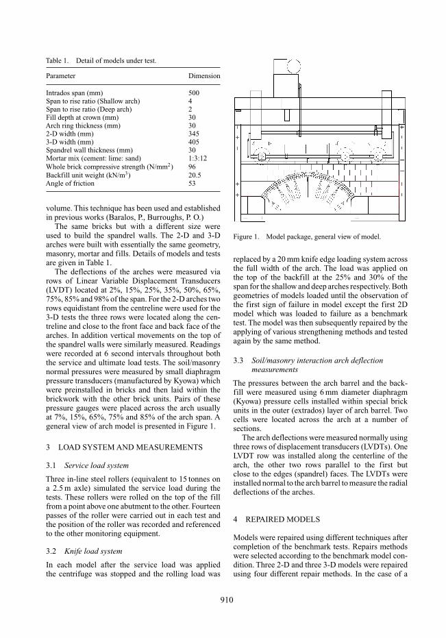
Table 1. Detail of models under test.
Parameter Dimension
Intrados span (mm) 500Span to rise ratio (Shallow arch) 4Span to rise ratio (Deep arch) 2Fill depth at crown (mm) 30Arch ring thickness (mm) 302-D width (mm) 3453-D width (mm) 405Spandrel wall thickness (mm) 30Mortar mix (cement: lime: sand) 1:3:12Whole brick compressive strength (N/mm2) 96Backfill unit weight (kN/m3) 20.5Angle of friction 53
volume. This technique has been used and establishedin previous works (Baralos, P., Burroughs, P. O.)
The same bricks but with a different size wereused to build the spandrel walls. The 2-D and 3-Darches were built with essentially the same geometry,masonry, mortar and fills. Details of models and testsare given in Table 1.
The deflections of the arches were measured viarows of Linear Variable Displacement Transducers(LVDT) located at 2%, 15%, 25%, 35%, 50%, 65%,75%, 85% and 98% of the span. For the 2-D arches tworows equidistant from the centreline were used for the3-D tests the three rows were located along the cen-treline and close to the front face and back face of thearches. In addition vertical movements on the top ofthe spandrel walls were similarly measured. Readingswere recorded at 6 second intervals throughout boththe service and ultimate load tests. The soil/masonrynormal pressures were measured by small diaphragmpressure transducers (manufactured by Kyowa) whichwere preinstalled in bricks and then laid within thebrickwork with the other brick units. Pairs of thesepressure gauges were placed across the arch usuallyat 7%, 15%, 65%, 75% and 85% of the arch span. Ageneral view of arch model is presented in Figure 1.
3 LOAD SYSTEM AND MEASUREMENTS
3.1 Service load system
Three in-line steel rollers (equivalent to 15 tonnes ona 2.5 m axle) simulated the service load during thetests. These rollers were rolled on the top of the fillfrom a point above one abutment to the other. Fourteenpasses of the roller were carried out in each test andthe position of the roller was recorded and referencedto the other monitoring equipment.
3.2 Knife load system
In each model after the service load was appliedthe centrifuge was stopped and the rolling load was
Figure 1. Model package, general view of model.
replaced by a 20 mm knife edge loading system acrossthe full width of the arch. The load was applied onthe top of the backfill at the 25% and 30% of thespan for the shallow and deep arches respectively. Bothgeometries of models loaded until the observation ofthe first sign of failure in model except the first 2Dmodel which was loaded to failure as a benchmarktest. The model was then subsequently repaired by theapplying of various strengthening methods and testedagain by the same method.
3.3 Soil/masonry interaction arch deflectionmeasurements
The pressures between the arch barrel and the back-fill were measured using 6 mm diameter diaphragm(Kyowa) pressure cells installed within special brickunits in the outer (extrados) layer of arch barrel. Twocells were located across the arch at a number ofsections.
The arch deflections were measured normally usingthree rows of displacement transducers (LVDTs). OneLVDT row was installed along the centerline of thearch, the other two rows parallel to the first butclose to the edges (spandrel) faces. The LVDTs wereinstalled normal to the arch barrel to measure the radialdeflections of the arches.
4 REPAIRED MODELS
Models were repaired using different techniques aftercompletion of the benchmark tests. Repairs methodswere selected according to the benchmark model con-dition. Three 2-D and three 3-D models were repairedusing four different repair methods. In the case of a
910
significant effect of the repair method in arch loadcapacity, the repair was repeated to the deep archgeometry.
4.1 Plastic mesh reinforcement
The second 2-D model (S2D-2R) was repaired usingplastic mesh reinforcement. Two mesh layers ofTENAX Promat (TENAX ) which was produced by theTENAX UK Limited Company for ground reinforce-ment and erosion control, were placed in the backfill.Top layer of the backfill was removed from the archbarrel, mesh layer was installed and the backfill wasreplaced again.
4.2 Concrete slab repair
Following the initial tests, S2D-3R and D2D-1R thearches were repaired by laying a reinforced con-crete slab on top of the backfill. In this case, theun-strengthened tests had a crown backfill depth of13 mm to readily facilitate the placement of the con-crete without overly distributing the damaged arches.The overall depth of construction over the crown ofthe arch, including the 17 mm of concrete layer in thestrengthened arches, was 30 mm.
The concrete itself was manufactured with 2.0 mmaggregate as the coarse material, Chelford 95 silicasand as the fine aggregate and OPC. (BS 12 1991),with mix proportion of 1:1.8:2.8:0.6 (cement: fine:coarse: water) by mass. Compressive strength testson 25 mm concrete cube samples yielded 56 N/mm2
according to British Standard (BS 1881-116). Themodel concrete was nominally reinforced with a meshof type 304 manufactured of 0.8 mm mild steel at20 mm centres.
4.3 Stitching the arch barrel
The first 3-D model was repaired by stitching thearch barrel with steel bars between the barrel andthe spandrel walls joints. The patterns of holes withan angle of 45 degree were drilled in the arch barreland 2.4 mm diameter stainless steel bars type 304 wasplaced in them.
4.4 Partial saddle concrete
Partial saddle concrete to the extrados of the arch wasemployed to repair the second 3-D arch. Strengtheningthe extrados of arch barrel is an appropriate methodof repairing arches. The advantage of this method isthat it not only strengthens the arch but also improvesload distribution and ties together any cracked sections(Department of Transport).
A 60 mm width of concrete slab was laid on bothedge of the arch barrel from one abutment to the
other one in the longitudinal direction.The saddle con-crete is stitched to the spandrels walls to avoid anydisconnection between the spandrel and barrel.
Two rows of holes with a depth equivalent to onering were initially drilled to the arch barrel and 2 mmsteel rods were installed in them using epoxy resin.These rods had an extra length of about 12 mm from thehole depth through the saddle and connected the barrelextrados to the saddle concrete. A width of 60 mm inmodel scale (that means 720 mm in prototype scale),was used which should be available as a pavement onmost of arch bridge or may be provided by restrictinga single lane of traffic to a narrow lane.
4.5 Spandrel wall strengthening
The third and fourth 3-D arches were repaired withstrengthening of their spandrel walls using a rein-forced concrete slab. After completing the benchmarktests, models were repaired by applying reinforcedconcrete to the inner sides of the spandrel walls. Thelocation of the concrete was restricted to those partsof the structure that would in normal circumstancesbe readily accessible for such work. In the presentstudy the vertical extent of the reinforced concrete wasrestricted to 100 mm in depth (about 1.2 m in the pro-totype) this would require only limited support duringconstruction.
5 TESTS RESULTS
Laboratory experiments have successfully been car-ried out on two different geometries of 1/12th scalesingle span centrifuge arch models. The experimentsprovided useful information on the effectiveness of thetested repair methods on the failure mechanism andparticularly on the service and ultimate load capacityof the arches. Final comparisons of all the repairedarches are presented in Figures 2 and 3 for the 2-D and3-D model tests.
The general conclusions are:
– The use of plastic mesh reinforcement, test S2D-2R,had no significant effect on arch load capacity andpressure distribution under applied loads.
– The relieving concrete slab on top of the backfill sig-nificantly increased the ultimate arch load capacityfor both shallow and deep arch geometries. The loadat failure of the shallow strengthened model was3.4 times that of the benchmark model and 2.7 ofthe average benchmark. The results for the repaireddeep arch were, respectively, 3.7 and 3.2 times asstrong as the benchmark arch. The application ofthe slab to the surface appears to be at least equiva-lent to application directly to the arch intrados andextrados.A concrete slab on top of the fill distributesthe pressure and decreases the recorded pressure on
911

Figure 2. Comparison between benchmark and repaired2-D Failure load.
Figure 3. Comparison between benchmark and repaired2-D Failure load.
the arch barrel significantly. A significant decreasein arch barrel deflection was observed under rollingloads.
– The first shallow 3-D arch was repaired using stain-less steel stitching bars applied to the arch barrel
to connect the extrados ring and spandrel walls toeach other. Test results showed no prevention of ringseparation by the stitching bars but an increase of50% in the ultimate arch load capacity followingapplication of this method.
– Applying a partial saddle concrete on part of the archbarrel in addition to steel bar connection of the con-crete to the spandrel increased the arch load capacityand the stiffness of the arch. The arch load capacitywas improved by about 215% for the repaired arch,which is comparable with applying the same con-crete on top and beneath the barrel in the 2-D archmodel tests.
REFERENCES
Sumon, S.K. Repair and strengthening of five full scalemasonry arch bridges. in Second International Conferenceon Arch Bridges. 1998. Venice, Italy.
Melbourne, C., M. Begimgil and M. Gilbert. The load testto collapse of a 5 M span brickwork arch bridge withtied spandrel walls. in Arch Bridges. 1995. Bolton: TomasTelford.
Ashurst, D. An assessment of repair and strengthening tech-niques for brick and stone masonry arch bridges. 1992,Transport Research Laboratory: Crowthorne.
Baralos, P. (2002). “The small-scale modelling of repair tech-niques for masonry arch bridges using a geotechnicalcentrifuge.,” PhD, University of Wales, Cardiff.
Burroughs, P. O. (2002). “A study of parameters that influencethe strength of masonry arch bridges using a geotechnicalcentrifuge,” PhD, University of Wales, Cardiff.
TENAX. (2002). “Ground Reinforcement and Erosion Con-trol, Product Guide and Price list." Tenax UK Limited.
BS 1881-116. (1983).Testing concrete – Method for determi-nation of compressive strength of concrete cubes, BritishStandard Institution, London.
Department of Transport. (1997a). “BA 16/97 – The Assess-ment of Highway Bridges and Structures.” HMSO,London.
912