compatibility of mixed weld metal - abarsazeha.com · compatibility of mixed weld metal by alvaro...
TRANSCRIPT

STRUCTURAL STEEL EDUCATIONAL COUNCIL
TECHNICAL INFORMATION & PRODUCT SERVICE
MARCH 1998
Compatibilityof
Mixed Weld Metal
By
Alvaro L. Collinand
James J. Putkey

Acknowledgments
The Authors wish to thank Pat Hassett, Rudy Hofer, Dave McEuen, and JamieWinans of the Structura l Steel Educat ion Council, and Roger Ferch of the HerrickCorporat ion for thei r review and comments.
The information presented in this publication has been prepared in accordance with recognizedengineering principles and is for general information only. While it is believed to be accurate,this information should not be used or relied upon for any specific application withoutcompetent professional examination and verif ication of its accuracy, suitability, andapplicability by a licensed professional engineer, designer, or architect. The publication of thematerial contained herein is not intended as a representation or warranty on the part of theStructural Steel Education Council or of any other person named herein that this informationis suitable for any general or particular use or of freedom from infringement of any patent orpatents. Anyone making use of this information assumes all liability arising from such use.
Caution must be exercised when relying upon other specifications and codes developed byother bodies and incorporated by reference herein since such material may be modified oramended from time to time subsequent to the printing of this edition. Structural Steel EducationCouncil bears no responsibility for such material other than to refer to it and incorporate it byreference at the time of the initial publication of this edition.
Index of Steel TIPS Publications
The following is a list of available Steel TIPS. Copies will be sent upon request. Some are invery limited quantity.
· Seismic Design of Special Concentrically Braced Frames
· Seismic Design of Eccentrically Braced Frames
· Seismic Design of Column Tree Moment Resisting Frames
· Dynamic Tension Tests of Simulated Moment Resisting Frame Welded Joints
· Reference Guide for Structural Steel Welding Practices
· Seismic Strengthening with Steel Slotted Bolt Connections
· Slotted Bolted Connection Energy Dissipaters
· Heavy Structural Shapes in Tension Applications
j l

INTRODUCTION
PURPOSE
The purpose of this Steel TIPS is to provide structural designers, fabricators, anderectors with the history, use, and compatibility of mixed weld metals forstructural steel applications.
ORGANIZATION AND CONTENT
To accomplish the purpose, the authors have organized this Steel TIPS into thefollowing categories:
Historical background.AWS and AISC requirements.Effect of the Northridge Earthquake.Combanations of mixed weld metal.
The authors do not recommend or approve any particular combination of mixedweld metal Instead, they set forth combinations used and possible combinations.Please remember, the Engineer has the right to approve any combination of mixedweld metal.
CONTENTS
ACKNOWLEDGMENTS
CONTENTS
INTRODUCTION
1. HISTORICAL BACKGROUND / 1
2. AMERICAN WELDING SOCIETY (AWS) REQUIREMENTS / 3
3. AISC REQUIREMENTS / 5
4. EFFECT OF 1994 NORTHRIDGE EARTHQUAKE / 8
5. IMPACT TESTING BEFORE NORTHRIDGE / 9
6. MIXED WELD METAL COMBINATIONS / 10
7. COMMENTARY ON IMPACT REQUIREMENTS AND IMPACT TESTING / 17
REFERENCES / 21

1. HISTORICAL BACKGROUND
For many years fabricators and erectors haveused, as common practice, electrodes withdifferent specifications and classifications in thesame weld (mixed weld metals). Mixed weldmetal results from:
Different root pass and fill-in passelectrodes.Weld repair work to both shop and fieldwelds.The more recent practice of making fieldwelds over shop welds.
Compatibility is a basic requirement of mixed weld metals. The differentelectrodes and the mixed weld metal must have, as a minimum, matching yieldstrength, tensile strength, and impact properties--if impact properties arespecified.
In this SteelTIPS, the authors will limit their discussion to two welding processes:
Shielded Metal Arc Welding (SMAW).Flux Cored Arc Welding (FCAW).
MIXING ELECTRODES.
In the Same Weld Process. First, fabricators and erectors commonly used differentmanual coated "stick" electrodes (SMAW) in the same weld. Then, when f lux coredelectrodes (FCAW) came on the market in the mid 1950's, they started usingdifferent FCAW electrodes in the same weld. They used the different electrodes:
To take advantage of one electrode's penetration capabilities for root passesand the other electrode's capabilities for fill-in passes.For weld repair work.
In Different Weld Processes. With the availability of self shielding f lux coredelectrodes, fabricators and erectors began using electrodes from the two differentwelding processes in the same weld. They used:
SMAW electrodes in the root passes for good penetration and Iow hydrogenproperties, and FCAW electrodes in the fill-in passes for high depositionrates.SMAW over FCAW for weld repair work.

FCAW With Outside Gas Shielding. With the availability of flux cored electrodeswith outside gas shielding in the mid 1960's, fabricators and erectors started usingtwo FCAW processes in the same weld:
Self-shielding from the flux in the core of the wire (FCAW-ss).Gas shielding from an outside source (FCAW-g).
Fabricators generally used:
FCAW-g in the root passes for good welding characteristics.FCAW-ss electrodes in fill-in passes for good deposition rates.
Outside gas shielding was generally limited to shop fabrication because erectorshad difficulty protecting the gas from winds encountered in field erection.
Interestingly, fabricators and erectors used Gas Metal Arc Welding (GMAW)equipment to make the first Flux Cored Arc Welds. GMAW equipment used solidwire electrodes with inert gas shielding. Users called this GMAW welding process"Dual Shielding." Now common practice is to call flux cored electrodes withoutside gas shielding (FCAW-g) as "Dual Shielding."
Since Northridge. Then the 1994 Northridge Earthquake occurred. Since theEarthquake, the volume of mixed weld metal has proliferated greatly, and with justabout any combination of SMAW and FCAW electrodes. Combinations resultedfrom both damage repair work and from new welds. Damage repair work involvedwelding one classification or process over another classification or process. Newdesign details set up the situation where erectors used one process to weld overa different shop process.
IMPACT REQUIREMENTS.
At first, the construction industry paid little regard to impact requirements of theelectrodes. Later, various Advisory Task Groups formed to investigate theEarthquake damage (e.g., AISC, AWS, SAC Joint Venture, SEAOC, LA City andCounty, and other Code Agencies) called for impact requirements in electrodesused in seismic designs. The various code agencies are putting these impactrequirements into their codes.
2. AMERICAN WELDING SOCIETY(AWS) REQUIREMENTS
The AWS Structural Welding Code--Steel (AWS t - - - - - • - • •Code) covers the welding requirements for • • 1welded steel structures. [1] This Code does not i \/ • Idirectly address the use of mixed weld metals or ' I ( • Iimpact requirements for welds. However, the • IAWS Code:
· Implies the use of mixed weld metals in Section 3.3.
Sets forth impact testing requirements in Annex III if the contract drawingsor specifications require impact testing.
MIXING WELD METALS
Base Metal/Filler Metal Combinations. Although the AWS Code does not directlyaddress the use of mixed weld metals, it does imply their use. Close attention tothe untitled table in Section 3.3, "Base Metal/Filler Metal Combinations," page 41,shows:
"Any steel to itself or any steel to another in the same group" can be weldedby "Any filler metal listed in the same group."
"Any steel in one group to any steel in another" can be welded by "Any fillermetal listed for a lower strength group. [SMAW electrodes shall be the Iowhydrogen classification]" (E7015, E7016, and E7018). [2]
Implications. Section 3.3 and Table 3.1 on page 42 show that many base metalsin asteel group can be welded to each other by different electrodes; therefore, theAWS Code allows mixed weld metal in the same weld based on strengthrelationships.
Additional Requirements by Advisory Task Groups. Besides compatible yieldstrength and tensile strength requirements required by the AWS Code, the AdvisoryTask Groups recommended that electrodes involved in mixed weld metal weldsmust have compatible impact requirements Further, the Advisory Task Groupsrecommended testing and evaluation of the mixed weld metal combinations.
IMPACT
Not Addressed in AWS Code. The AWS Code does not address impactrequirements; that is the Engineer's responsibility. However, the AWS Code doesaddress impact testing requirements in Annex III.

IMPACT TESTING
Application of Annex III of the AWS Code. Annex III of the AWS Code addressesimpact testing. The title of Annex III is "Requirements for Impact Testing" with asubtitle "Mandatory Information." A further comment under the subtitle states:
(This Annex is a part of ANSI/AWS D1.1-96, Structural WeldingCode--Steel and includes mandatory requirements for use in thisstandard.) [3]
However, Section III1.1 states:
The impact test requirements and test procedures in this Annex shallapply only when specified in the contract drawings or specifications inaccordance with 5.26.5(3)[d] and 4.1.1.3, and Table 3.1 of this code. [4]
Thus, the decision to call for impact testing requirements is left to the discretionof the designer or engineer responsible for the contract drawings or specifications.
Use of Test Results. Annex Section III1.2 states in part:
. . . The energy values determined are qualitative comparisons on aselected specimen and although frequently specified as an acceptancecriterion, they cannot be used directly as energy figures that wouldserve for engineering calculations [e.g., failure analysis calculations]. [5]
Scatter. A great scatter is normal in Charpy V-Notch test results. The AWS Codeprovides a limited discussion of scatter in Annex Ill; however, it references otherpublications that thoroughly discuss fracture toughness--including scatter. AnnexIII, Table II1-1, calls for three specimens for each test location, with an optional fivespecimens per test location. When using five specimens, Note 2 in the Tableapplies and states in part, "The highest and lowest values are then discarded tominimize some of the scatter normally associated with Charpy testing of welds andHAZ. [Emphasis added.]" [6] HAZ denotes the portion of the base metal whosemechanical properties or microstructure has been altered by the heat of weldingand quenching effect of the base metal. See Article 7, "Commentary on ImpactRequirements and Testing," for comments on impact testing and scatter.
4

3. AISCREQUIREMENTS
The AISC Manual of Steel Construction:AIIowableStress Design(AiSC Manual) addressesmixing weld metals and impact requirements forboth the base metal and weld metals as follows:
Mixed Weld Metal. PART 5-Specifications and Codes, Specification forStructural Steel Buildings--Allowable Stress Design and Plastic Design (AISCSpecifications), discusses mixing weld metals.
Impact. PART 1-Dimensions and Properties, briefly discusses impact. PART5 -Specifications and Codes, addresses limited impact requirements. [7]
MIXING WELD METALS
AISC Specifications. Refer to Chapter J-Connections, Joints and Fasteners. SectionJ2.6., Mixed Weld Metal, states:
6. Mixed Weld Metal
When notch-toughness is specified, the process consumables for allweld metal, tack welds, root pass and subsequent passes,deposited in a joint shall be compatible to assure notch-toughcomposite weld metal. [8]
The following AISC Specification Commentary illustrates a lack of compatibilitybetween process consumables (electrodes), and reinforces the Advisory TaskGroups' recommendation that users evaluate mixed weld metals by testing.
AISC Specifications Commentary. Section C-J2.6., Mixed Weld Metal, states:
6. Mixed Weld Metal
Instances have been reported in which tack welds deposited usinga self-shielded process with aluminum deoxidizers (which by itselfprovided notch-tough weld metal) were subsequently covered byweld passes using a submerged arc process (which by itselfprovided notch-tough weld metal) resulted in composite weld metalwith Iow notch-toughness (Terashima and Hart, 1984; Kotecki andMoll, 1970; and Kotecki and Moll, 1972). [9]

IMPACT
PART I Dimensions and Properties. Pages 1-4, 1-5, and 1-6 have very good,concise write-ups on Brittle Fracture, Lamellar Tearing, and Jumbo Shapes andHeavy Welded Built-up Sections. However, PART 1 barely touches on notch-toughness (im pact). The last paragraph under the subtopic "Selecting a Steel" doesmention notch toughness.
PART 5 Specifications and Codes. The Specifications and correspondingCommentary address impact in Sections A3.1.c. Heavy Shapes, A4.2. Impact, andA.4.5. Other Forces. Engineers seldom request impact requirements for basemetal, except for heavy shapes. See below.
Section A3.1.c. Heavy Shapes specifies impact requirements for the followingmembers when subject to primary tensile stresses due to tension or flexure ifspliced using full penetrauon welds:
ASTM A6 Groups 4 and 5 rolled shapes.Built-up members with plates exceeding 2 in. thick
For this use the contract documents shall specify, "... the steel shall be specifiedin the contract documents to be supplied with Charpy V-Notch testing inaccordance withASTMA6, Supplementary Requirement S5. The impact test shallmeet a minimum average value of 20 ft-lbs, absorbed energy at +70°F . . . . " [10]
When using mixed weld metal in Groups 4 and 5 rolled heavy shapes, the designeror engineer, fabricator, and erector, should be familiar with impact requirementsand precautions addressed in:
Section A3.1.c.The Section's Commentary.All sectaons listed In Section A3 1 c on page 5-126, Includingcorresponding commentary sections
The Section also states in part:
The above supplementary toughness requirements shall also beconsidered for welded full-penetration joints other than splices in heavyrolled and built-up members subject to primary tensile stresses. [11]
The Specification Commentary discusses "considered."
Section A4.2. Impact, does not call for Charpy V-Notch toughness testing. TheSection states:
2. Impact
For structures carrying live loads* which induce impact, theassumed live load shall be increased sufficiently to provide forsame.If not otherwise specified, the increase shall be not less than:

[See pages 5-29 for listings ranging from 10% - 100%][The * footnote is not included in the above quote] [12]
Note: The listed percentages increase the live loads to compensate for loads thatinduce impact.
Section A4.5. Other Forces, states:
5. Other Forces
Structures in localities subject to earthquakes, hurricanes and otherextraordinary conditions shall be designed with due regard for suchconditions. [13]

1 1 1 EFFECT OF 1994NORTHRIDGEEARTHQUAKE
As Mentioned in Article 1, "HistoricalBackground," fabricators and erectors had usedelectrodes with different specifications andclassifications for many years before theNorthridge Earthquake.
MIXED WELD METALS
1 .20°F
Northridge Damage Repairs. The use of mixed weld metals increased following theEarthquake, mainly because damage repairs involved gouging out for weld cracks,and rewelding with an electrode other than the electrode used in the original weld.Erectors most commonly used--and continue to use--SMAW E701 8 Iow hydrogen,manual electrodes and certain FCAW electrodes to repair damaged weld jointsmade with FCAW, E70T-4 flux cored electrodes.
New Welds. Engineers started following the Advisory Task Group'srecommendation of requiring impact tests for mixed weld metals in new welds.
IMPACT REQUIREMENTS
Northridge Damage Repairs. During initial damage repairs, engineers paid littleattention to the impact requirements of the original weld metal and the repairelectrode because:
Expediency of the repairs precluded investigative testing.
AWS Code and the AISC Specifications did not have any impact requirementsfor base metals--except for limited requirements by AISC for Steel Groups 4and 5 jumbo shapes and certain built-up members. (See Specification A3.1 .Creviewed in Article 3, "AISC Requirements").
SMAW and FCAW repair electrodes had good impact requirements--usually20 ft. lbs. at-20°F.
As repair work progressed, the Investigating Advisory Task Groups made theirrecommendations available. Engineers expressed concern about therecommendations regarding impact requirements of the original weld metal andthe repair weld metal. However, engineers apparently took no action regardingrecommendations on the original weld metal, but did follow recommendations onrepair weld metal.
New Welds. Later, the Advisory Task Groups recommended that if engineerswanted impact requirements for mixed weld metal, each electrode used to makethe weld had to meet those impact requirements. As a result, engineers nowfrequently request impact requirements for both SMAW and FCAW electrodes.
8

11 IMPACT REQUIREMENTSAND IMPACT TESTINGBEFORE NORTHRIDGE
Most of the structural steel construction beforethe 1994 Northridge Earthquake had very littleimpact requirements because:
Applicable editions of the AWS Code hadno impact requirements.Applicable editions of the AISC Manual hadlimited or no impact requirements.
AWS IMPACT REQUIREMENTS
%
In AWS Code. Various AWS Codes governed the construction of structuressubjected to the Northridge Earthquake. The 1988, 1990, and 1994 AWS Codesincluded Appendix Ills that are almost identical to Annex III in the 1996 AWS Code.Therefore, the present AWS impact requirements limited to impacttesting--reviewed in Article 2, "AWS Requirements"--applied to structures builtunder the earlier named codes. Before 1988 the AWS Code lacked even thoseimpact testing requirements.
AISC IMPACT REQUIREMENTS
In AISC Manual. Various AISC Manuals governed construction of structuressubjected to the Northridge Earthquake. The 1980 AISC Manual included 1978Specifications sim ilar to the 1989 AISC Manual Therefore, the present AISC im pactrequirements--reviewed in Article 2, "AISC Requirements"--applied to structuresbuilt from 1978to 1994. Before 1978, the AISC Manual did not address impactrequirements.
6. MIXED WELD METALCOMBINATIONS
The use of mixed weld metal combinations canbe divided into the following three main periodsbased on the different conditions for thecombinations during the periods:
1. Pre-Northridge Earthquake Practice.2. Urgent Northridge Earthquake Damage Repairs.3. Post-Northridge Earthquake Practice.
The following "General Criteria," "Conditions" listed under a Period, and criteriawithin the tables, decided the electrode combinations used for each period.
GENERAL CRITERIA
The following criteria pertain to electrodes listed in Period 1, 2, and 3 tables:
Root weld passes require good penetration and good fusion to base metals.Fill-in weld passes require good fusion to base metals and to other passes.The AWS Welding Handbook and electrode manufacturers' bulletins containelectrode information and specifications. [14]FCAW-ss and FCAW-g electrodes make good fill-in passes because of theirhigher deposition rates. However, outside gas shielded electrodes createproblems in field welding because the shielding gas must be protected fromthe wind.The Engineer may require approval of mixed weld metal including electrodecombinations previously qualified by test.
The following AWS Specifications give root pass, fill-in pass, and impactrequirements for electrodes listed in Period 1, 2, and 3 tables:
AWS AS. 1 Specification for Carbon Steel Electrodes for Shielded Metal ArcWelding. [ 15 ]AWS AS. 5 Specification for Low Alloy Steel Electrodes for Shielded Metal ArcWelding. [16]AWS A5.20 Specification for Carbon Steel Electrodes for Flux Cored ArcWelding. [17]AWS A5.29 Specification for Low Alloy Steel Electrodes for Flux Cored ArcWelding. [18]
10
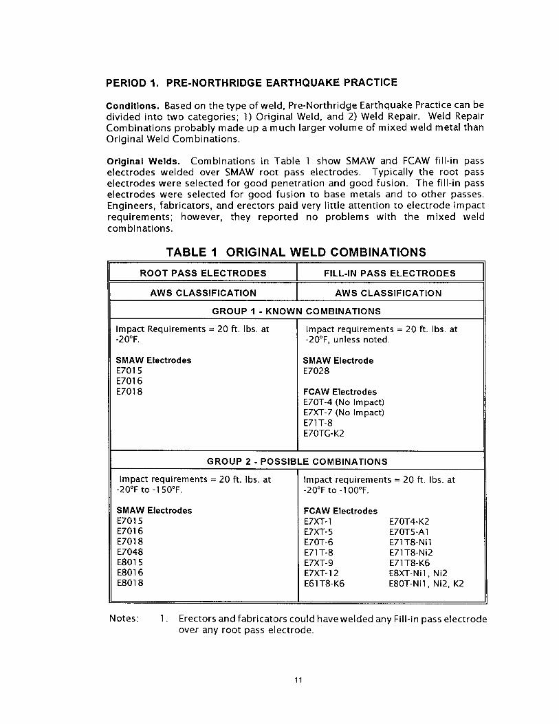
PERIOD 1. PRE-NORTHRIDGE EARTHQUAKE PRACTICE
Conditions. Based on the type of weld, Pre-Northridge Earthquake Practice can bedivided into two categories; 1) Original Weld, and 2) Weld Repair. Weld RepairCombinations probably made up a much larger volume of mixed weld metal thanOriginal Weld Combinations.
Original Welds. Combinations in Table 1 show SMAW and FCAW fill-in passelectrodes welded over SMAW root pass electrodes. Typically the root passelectrodes were selected for good penetration and good fusion. The fill-in passelectrodes were selected for good fusion to base metals and to other passes.Engineers, fabricators, and erectors paid very little attention to electrode impactrequirements; however, they reported no problems with the mixed weldcombinations.
TABLE 1 ORIGINAL WELD COMBINATIONS
ROOT PASS ELECTRODES
AWS CLASSIFICATION
GROUP 1 - KNOWN
FILL-IN PASS ELECTRODES
AWS CLASSIFICATION
COMBINATIONS
Impact Requirements = 20 ft. lbs. at-20°F.
SMAW ElectrodesE701 5E701 6E701 8
Impact requirements = 20 ft. lbs. at-20°F, unless noted.
SMAW ElectrodeE7028
FCAW ElectrodesE70T-4 (No Impact)E7XT-7 (No Impact)E71T-8E70TG-K2
GROUP 2 - POSSIBLE COMBINATIONS
Impact requirements = 20 ft. lbs. at-20°F to -1 50°F.
SMAW ElectrodesE701 5E701 6E701 8E7048E801 5E801 6E801 8
Impact requirements = 20 ft. lbs. at-20°F to -1 00°F.
FCAW ElectrodesE7XT- 1 E70T4- K2E7XT- 5 E70TS-A 1E70T-6 E71T8-NilE71T-8 E71T8-Ni2E7XT-9 E71T8-K6E7XT-12 E8XT-Nil, Ni2E61T8-K6 E80T-Nil, Ni2, K2
Notes: 1. Erectors and fabricators could have welded any Fill-in pass electrodeover any root pass electrode.
11

Weld Repairs. Combinations in Table 2 show SMAW and FCAW weld repairelectrodes welded over SMAW and FCAW original weld electrodes. Fabricators anderectors used a multitude of electrode combinations to make weld repairs to shopand field welds. Repair items included'
Undercut.Cracks, porosity, incomplete fusion, and slag inclusion.Undersized welds.Lamellar tearing (gouging into adjacent weld metal required).
Fabricators and erectors could have made the original weld with SMAW, FCAW,GMAW, or SAW electrodes. SMAW and FCAW electrodes usually made up the repairelectrodes.
TABLE 2 WELD REPAIR COMBINATIONS
ORIGINAL WELD ELECTRODES WELD REPAIR ELECTRODES
AWS CLASSIFICATION AWS CLASSIFICATION
Impact requirements = 20 ft. lbs. at-20°F, unless noted.
SMAW ElectrodesE701 5E7016E7018E7028
FCAW ElectrodesE70T-4 (No Impact)E7XT-7 (No Impact)E7XT-8E70TG-K2
Impact requirements = 20 ft. lbs. at-20°F, unless noted.
SMAW ElectrodesE701 5E701 6E701 8
FCAW ElectrodesE70T-4 (No Impact)E7XT-7 (No Impact)E7XT-8E70TG- K2
Notes: 1.
.
Electrodes listed under "Original Electrodes" are taken from"Group 1-Known Combinations" in Table 1.
Erectors and fabricators could have welded any repair electrodeover any existing weld electrode.
12

PERIOD 2. URGENT NORTHRIDGE EARTHQUAKE DAMAGE REPAIRS
Conditions. Combinations in Table 3 show SMAW repair weld electrodes weldedover SMAW and FCAW electrodes in the existing weld. FCAW electrodes werereadily available for damage repairs. They were very popular, high depositelectrodes. However, for the emergency damage repairs immediately following theearthquake, erectors commonly used SMAW Iow hydrogen electrodes welded overa gouged out joint made with SMAW or FCAW electrodes.
Most of the weld joint damage consisted of a lack of fusion of the weld metal tothe base metal. Erectors repaired this type of damage by:
Back-gouging the joint to clean base metal and clean weld metal.Grinding to clean up.Rewelding fill-in and build-up with E70XX electrodes.
Again, engineers and erectors paid little attention to electrode impactrequirements of the resulting mixed weld metal joint, although they suspectedmost original welds were made with FCAW E70T-4 electrodes that had no impactrequirements. Engineers accepted most of the combinations in Table 3, withacceptance based on normal welding procedures.
TABLE 3URGENT EARTHQUAKE DAMAGE REPAIR COMBINATIONS
EXISTING WELD ELECTRODES REPAIR WELD ELECTRODES
AWS CLASSIFICATION AWS CLASSIFICATION
Impact requirements = 20 ft. lbs. at-20°F, unless noted.
SMAW ElectrodesE701 5E701 6E701 8E7028
FCAW ElectrodesE70T-4 (No Impact)E7XT-7 (no Impact)E7XT-8E70TG-K2
Impact requirements = 20 ft. lbs. at-20°F.
SMAW ElectrodesE701 5E7016E701 8
Notes: 1. Erectors could have welded any repair electrode over any existingweld electrode.
13

PERIOD 3. POST-NORTHRIDGE EARTHQUAKE PRACTICE
Conditions. Based on the type of welding, Post-Northridge Earthquake Practice canbe subdivided into two categories:
Later Northridge Earthquake damage repairs.New welds.
Later Northridge Earthquake Damage Repairs. After completing the urgentNorthridge Earthquake damage repairs, erectors started making "later" damagerepairs. Erectors made these later damage repairs under criteria based on reportsby the Advisory Task Groups. The Advisory Task Groups unanimouslyrecommended that all electrodes in aweld metal combination shall have matchingphysical properties (e.g., yield strength, tensile strength, and elongation) andcompatible impact Requirements--usually 20 ft. lbs. at -20°F. Combinations inTable 4 show SMAW or FCAW repair electrodes welded over SMAW or FCAWelectrodes in the existing weld.
TABLE 4 LATER DAMAGE REPAIR WELD COMBINATIONS
EXISTING WELD ELECTRODES REPAIR WELD ELECTRODES
AWS CLASSIFICATION AWS CLASSIFICATION
Impact requirements = 20 ft. lbs at-20°F, unless noted.
SMAW ElectrodesE701 5E701 6E701 8E7028
FCAW ElectrodesE70T-4 (No Impact)E70T-7 (No Impact)E71T-8E70TG- K2
Impact requirements = 20 ft. lbs. at-20°F.
SMAWElectrodesE7015E7016E7018
FCAW ElectrodesE71T-8E70TG -K2
Notes: 1. Erectors could have welded any repair electrode over any existingweld electrode.
14

NewWelds. Criteria developed by the Advisory Task Groups and new joint designsdeveloped by engineers have increased the use of mixed weld combinations. Thefollowing situations may require mixed weld metal:
1. Back-up bar removal with subsequent fill-in and build-up.2. Beam flange weld to column flange with a shop welded cover plate acting as
a back-up bar.3. Beam web weld to column flange with a shop welded shear plate acting as a
back-up bar.4. Column splice weld over box column shop weld.
Test Program Combinations. The James F. Lincoln Arc Welding Foundation isconducting tests on compatibility of various electrode combinations. See theFoundation's publication "Fabricators' and Erectors' Guide to Welded SteelConstruction" for a discussion of mixing weld metal and for test results. [1 9] Table5.3 in the Guide gives intermixing recommendations. Most combinations listed anthe Table meet the Advisory Task Groups' impact requirements, although someindividual electrodes have no specified impact requirements.
Currently Used Combinations. The authors have helped develop or have learnedof various combinations of mixed weld metal. Table 5 shows some currently usedcombinations of FCAW electrodes welded over SMAW electrodes or other FCAWelectrodes.
15

TABLE 5 NEW WELD COMBINATIONS
ROOT PASS OR FILL-IN PASS APPLICATIONSBASE WELD ELECTRODES OF
ELECTRODES WELD COMBINATIONS
AWS CLASSIFICATION
E701 8 E71T-8 Beam flange to column flange
E70T-6 E71T-8 Make column splice smooth
E70T-6 E71T-8 Overlay from back-up bar removal
E70T-7 E71T-8 Make column splice smooth(No impact)
E70T-1 E71T-8 Column splice weld over shop weld onbox column
E70T-1 E71T-8 Beam flange to column flange weld overshop weld on cover plate
E70T-1 E71T-8 Beam web to column flange weld overshop weld on shear plate
E70T-1 E70T-6 Column splice weld over shop weld onbox column
E70T-1 E70T-6 Beam flange to column flange weld overshop weld on cover plate
I
ETOT-1 E70TG-K2 Column splice weld over shop weld onbox column
E70TG-K2 E70T-6 Beam bottom flange to column flange
E70TG-K2 E71T-8 Beam bottom flange to column flange
E70T-1 E70TG-K2 over Test, Joint B-U4a-GFE71T8-Nil
E71T-8 E70T-6 Test, Joint B-U2a-F
Notes: 1. The fill-in pass electrodes are welded over root pass electrodes orbase weld electrodes.
2. Each row shows a specific weld combination.3. Electrode impact requirements vary from 20 ft. lbs. to 45 ft. lbs. at
-20°F, unless noted.4. New weld repairs also use the combinations shown in Table 5.5. Fabricating shops use the ETOT-I classification (FCAW-g) electrode.6. The Engineer may require approval of any mixed weld metal
combination.
16

7. COMMENTARY ONIMPACT REQUIREMENTSAND IMPACT TESTING , , ,,7
This Article gives the authors' personal views on 'L•' {Iimpact requirements and impact testing. The /7/text in this Article 7 assumes the Engineer /•z/.c.•___•specifies impact requirements and impact '%.testing requirements.
IMPACT REQUIREMENTS
Welding Electrodes. AWSSpecificationsAWSAS.1,AS.5, A5.20, andA$.29 giveimpact requirements for commonly used welding electrodes. See "General Criteria"in Article 6, "Mixed Weld Combinations," for complete Specification titles.Approximately 60 to 75 percent of the specified electrodes have impactrequirements of 20 ft. lbs. at -20°F. So specifying SMAW and FCAW weldingelectrodes with proper impact requirements is not a problem. We recommend theEngineer specify the electrode impact requirements in the project Specifications,just like the Engineer specifies the grade of steel for the project.
Base Metal. Most structural steels in the AISC Specifications have no impactrequirements. An exception is ASTM A6 Steel Groups 4 and 5 hot-rolled shapesand welded sections made of plate with a minimum thickness of 2 in. Theseshapes and sections need impact requirements of 20 ft. lbs. at 70°F, under certaintension stresses and with complete joint penetration welded splices (See Article 3,"AISC Requirements"). These are not strict impact requirements, especially whenmost SMAW and FCAW electrodes have impact properties of 20 ft lbs at -20°F.
AWS Welding Handbook, Figure 12.18 on page 400, "Typical Transition Curve forMild Steel Plate," shows absorbed energy values. [14] For temperate zones,especially if the structural steel frame is enclosed, mild steel and Iow alloy highstrength steels have absorbed energy values of 20 ft. lbs. to 40 ft. lbs. at 25°F to750F.
However, for very Iow temperature zones, (e.g., the North Slope in Alaska, Parts ofCanada, and the Rocky Mountains), the Handbook recommends the Engineerspecify a minimum impact requirement. We will always be indebted to the CharpyV-Notch impact test for pointing out in World War II how cold water temperaturescaused brittle fracture on ships. Recent discoveries and a review of eyewitnessaccounts now confirm the passenger ship TITANIC experienced brittle fracturefailure when colliding with the iceberg and when sinking.
IMPACT TESTING
Charpy V-Notch Test. The Steel Industry extensively uses the Charpy V-Notch
17

Impact Test on its steel products--including weld metal. Test specimens are smallbars--machined, ground, and notched, usually 10mm x 10mm x 55mm in length(0.394 in. x 0.394 in. x 2.165 in.). A specially designed testing machine supportsthe specimens in the horizontal position. A pendulum force strikes and breaks thespecimen with asingle blow, with the pendulum force striking on the side oppositethe notch. The testing machine measures and records the energy absorbed inbreaking the test specimen.
Other Standard Methods. Besides CharpyV-Notch testing, ASTM A370-92 StandardTest Methods and Definitions for Mechanical Testing of Steel Products and ASTME23-88 Standard Test Methods for Notched Bar Impact Tes ting of Metallic Materialsaddress the following other methods of impact testing:
The Izod V-Notch Test (broken in vertical cantilever action).The Drop Weight Test--developed by the U.S. Navy National ResearchLaboratory.The Crack Tip Opening Displacement Test (CTOD). [20,21]
AWS Requirements. Annex III of the AWS Code sets forth the following impacttesting requirements'
Three Specimens. Table II1-1 calls for a set of three test specimens for eachtest location. The Engineer has the responsibility to specify the followingitems on the contract drawings or specifications:
Test temperature.Minimum average energy value per set of three (location).Minimum energy value per specimen from any set.
Five Specimens. An optional test--probably used Jn 75 to 80 percent oftests--allows a set of five test specimens for each location with the highestand lowest values discarded. The result is the average value for the threemiddle specimens. Discarding the highest and lowest values minimizes thevariations (scatter) normally associated with Charpy V-Notch test results ofwelds and Heat Affected Zone (HAZ). See Table II1-1, Note No. 2.
Specimen Location. Figure II1-1 notes the locations of the test specimensfrom the weld centerline, the Heat Affected Zone, and the weld face.
Scatter. Charpy V-Notch test results have large variations (great scatter) becauseof many potential differences in testing procedures This scatter of test resultssets up a difficult situation to make a judgment when only a single specimen istested at each location. Unfortunately the evidence--or lack of evidence--indicatesthe single test is generally the procedure followed. Differences in testingprocedures contributing to scatter include:
Material strength and thickness.Heat input of the weld specimen.Roiling direction of grain orientation.Variations in testing procedures.Small specimens.
18
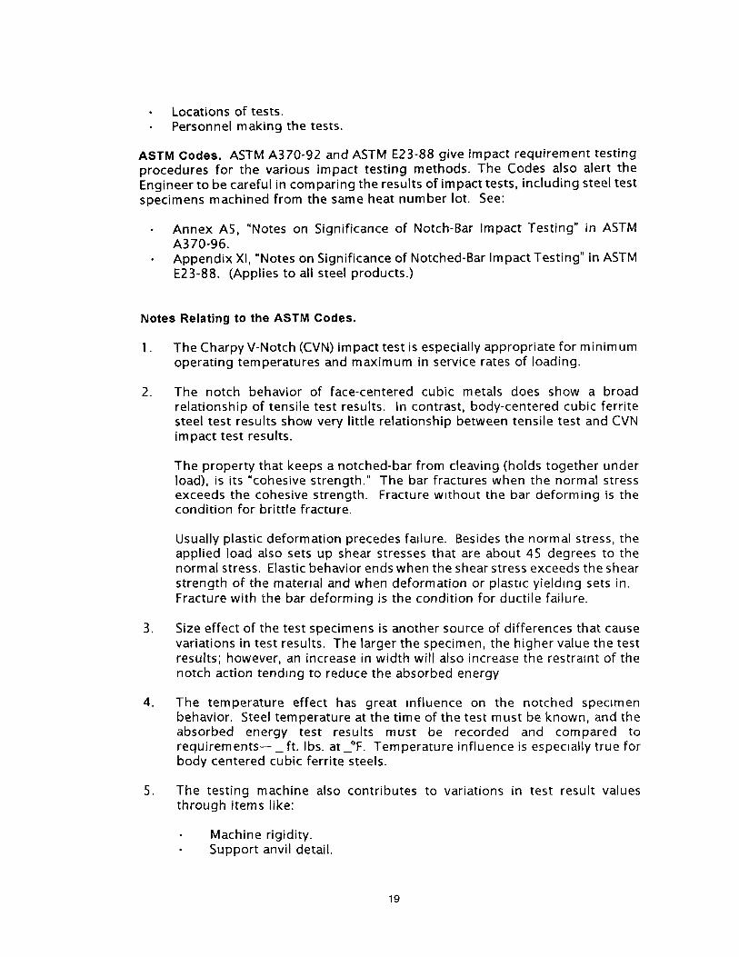
Locations of tests.Personnel making the tests.
ASTM Codes. ASTM A370-92 and ASTM E23-88 give impact requirement testingprocedures for the various impact testing methods. The Codes also alert theEngineer to be careful in comparing the results of impact tests, including steel testspecimens machined from the same heat number lot. See:
Annex AS, "Notes on Significance of Notch-Bar Impact Testing" in ASTMA370-96.Appendix Xl, "Notes on Significance of Notched-Bar Impact Testing" in ASTME23-88. (Applies to all steel products.)
Notes Relating to the ASTM Codes.
. The Charpy V-Notch (CVN) impact test is especially appropriate for minimumoperating temperatures and maximum in service rates of loading.
. The notch behavior of face-centered cubic metals does show a broadrelationship of tensile test results. In contrast, body-centered cubic ferritesteel test results show very little relationship between tensile test and CVNimpact test results.
The property that keeps a notched-bar from cleaving (holds together underload), is its "cohesive strength." The bar fractures when the normal stressexceeds the cohesive strength. Fracture without the bar deforming is thecondition for brittle fracture.
Usually plastic deformation precedesfadure. Besides the normal stress, theapplied load also sets up shear stresses that are about 45 degrees to thenormal stress. Elastic behavior ends when the shear stress exceeds the shearstrength of the material and when deformation or plasuc yielding sets in.Fracture with the bar deforming is the condition for ductile failure.
. Size effect of the test specimens is another source of differences that causevariations in test results. The larger the specimen, the higher value the testresults; however, an increase in width will also increase the restraint of thenotch action tending to reduce the absorbed energy
. The temperature effect has great influence on the notched specimenbehavior. Steel temperature at the time of the test must be known, and theabsorbed energy test results must be recorded and compared torequirements--_ft , lbs. at_°F. Temperature influence is especially true forbody centered cubic ferrite steels.
. The testing machine also contributes to variations in test result valuesthrough items like:
Machine rigidity.Support anvil detail.
19
.
.
.
Pendulum striking of the specimen (not squarely).Details of the machine anchor bolts.
While Charpy or Izod tests may not directly predict the ductile or brittlebehavior of the steel specimens or of large masses (large structures), the testresults can serve as acceptance criteria.
The Engineer must recognize that the project Specifications in the BidDocuments should specify:
The dimensional detail of the specimens.Base metal material.Weld deposit material.The testing procedure.
The Engineer must know a structure's operating conditions, and set the testresults the Engineer is trying to achieve The engineer should also bethoroughly familiar with typical absorbed energy transition curves (ft. lbs. at°F) for the types of steel to be use on the project.
20

REFERENCE
1. Structural
2. Structural
3. Structural
4. Structural
5. Structural
6. Structural
7.
.
9.
10.
11.
12.
13.
14.
15.
16.
17.
18.
19.
20.
21.
LIST
Welding Code--Steel D1.1-96, AWS, Miami, 1996.
Welding Code--Steel, p. 41.
Welding Code--Steel, p. 235.
Welding Code--Steel, p. 235.
Welding Code--Steel, p. 235.
Welding Code--Steel, p. 237.
ManualofSteelConstruction:AIIowableStress Design, 9th ed., AISC, Chicago,1989.
Manual of Steel Construction
Manual of Steel Construction
Manual of Steel Construction
Manual of Steel Construction
Manual of Steel Construction
Manual of Steel Construction p
Welding Handbook, 8th ed., Vol
p. 5-69
p. 5-165.
p. 5-26.
p. 5-27.
p. 5-29.
5-30.
1, AWS, Miami, 1987.
AWS A5.1 Specification for Carbon Steel Electrodes for Shielded Metal ArcWelding, AWS, Miami, 1991.
AWS AS. 5 Specification for Low Alloy Steel Electrodes for Shielded Metal ArcWelding, AWS, Miami, 1996.
AWS A5.20 Specification for Carbon Steel Electrodes for Flux Cored ArcWelding, AWS, Miami, 1980.
AWS A5.29 Specification for Low Alloy Steel Electrodes for Flux Cored ArcWelding, AWS, Miami, 1995.
Fabricators' and Erectors' Guide to Welded Steel Construction, The James FLincoln Arc Welding Foundation, Cleveland, 1997.
ASTM A370-92' Standard Test Methods and Definitions for MechanicalTesting of Steel Products, ASTM, Philadelphia, 1992.
ASTM E23-88' Standard Test Methods for Notched Bar Impact Testing ofMetallic Materials, ASTM, Philadelphia, 1988.
21

ABOUT THE AUTHORS
Alvaro L. Collin is a Consulting Engineer with California registration in CivilEngineering and Metallurgical Engineering. He received a BS degree from theUniversity of California, Berkeley, in 1941 as a Civil Engineering major and aMechanical Engineering minor. He spent 24 years with Kaiser Steel Corporation asManager of Engineering of the Fabrication Division, Southern California, and SeniorDevelopment Engineer, Steel manufacturing Division, Oakland, CA. Al has beenconsulting the past 17years on welded construction, heavy equipment design andmaterial handling systems.
Mr. Collin is a life member of the Structural Engineers Association of NorthernCalifornia. He has been a member of the Board of Directors and the Steel andSeismic committees of SEAONC. He is a Iongtime member of the AmericanWelding Society, having served on the National Board of Directors, on the NationalQualification and Certification Committee, and as chairman to the Los Angeles andSan Francisco sections. Al has been awarded the National, District and SectionMeritorious Awards of AWS. Recently, he was awarded national honorarymembership in theAWS. He has served on AISC and AISI Code Committee TaskGroups, the SAC Joint Venture Task Group, and is a member of the EarthquakeEngineering Research Institute.
James J. Putkey is a consulting civil engineer in Moraga, California. He receiveda BCE degree from the University of Santa Clara in 1954. He served two years inthe U.S. Army, and then spent 19 years with the Erection Department of BethlehemSteel Corporation--Pacific Coast Division, and seven years with the University ofCalifornia--Office of the President. After leaving the University, Jim started his ownconsulting business. He has provided consulting services to owners, contractors,attorneys, and steel erectors for the past 1 7 years.
Jim is now "Semi-Retired." However, he still serves as a hearing officer for theUniversity of California, and occasionally writes construction related articles.
22

STRUCTURAL STEEL EDUCATIONAL COUNCIL470 Fernwood DriveMoraga, CA 94556
(510) 631-9570
GSPONSORS
Adams & Smith
Allied Steel Co., Inc.
Bannister Steel, Inc.
Baresel Corp.
Bethlehem Steel Corporation
C.A. Buchen Corporation
Butler Manufacturing Co.
G.M. Iron Works Co.
The Herrick Corporation
Hoertig Iron Works
Hogan Mfg., Inc.
Junior Steel Co.
Lee & Daniel
McLean Steel, Inc.
Martin Iron Works, Inc.
MidWest Steel Erection
Nelson Stud Welding Co.
Oregon Steel Mills
PDM Strocal, Inc.
Reno Iron Works
H.H. Robertson Co.
SME Industries
Southland Iron Works
Stockton Steel
Verco Manufacturing, Inc.
Vulcraft Sales Corp.
!
The local structural steel industry (above sponsors) stands ready to assist you in detemuning i • 'iec0nomicat solution for your products. Our assistance can range from budget prices and e s t i m a t e d • ]to cost comparisons, fabrication details and delivery schedules. ]
I
Funding for this publication provided by the California Iron Workers Administrative Trust.