compendium of industrial painting & coating processes · pdf fileof industrial painting...
TRANSCRIPT

1
Compendium
Of
Industrial Painting & Coating Processes
For
Machine Tools
Indian Machine Tool Manufacturers’ Association
www.imtma.in
2015
2
Contents
Foreword
1. Basics of Paint on Machine Tool
2. Industrial Painting and Coating
3. Surface Preparation – A guide for the users
4. Coating Application Types and Technologies
5. Comparison of Coatings
6. Paint Trouble Shooting – Paint Problems and Solutions
7. Pollution Prevention for the Coating Industry
8. Proper Coating Techniques for Operators
9. Inspection of Paints/QP for Painting
Annexures
Annexure 1 List of Indian Standard for painting procedure for
Machine Tools & other related standards
Annexure 2 Overview of Paint shops in some of the repute
Machine Tool Industries
Annexure 3 List of paint testing equipment
Acknowledgement
References/Sources
3
Foreword
IMTMA is bringing out the 1st edition of “Guide Book on Industrial Painting & Coating Processes for
Machine Tools” to strengthen the supply chain for the benefit of the Indian Machine Tool Industry.
This reference book will lay down the basics of paint applications, coating types and technologies,
common paint problems with possible solutions relevant to the machine tool industry
The content of the manual is described from various related websites, manufacturers’ guidelines
and machine tool builders’ feedback. Important topics are discussed and focused in order to
enlighten the knowledge of industrial paints and coating processes.
Every effort has been made to make this handbook as ‘complete and accurate as possible’.
Nevertheless, it is likely that some aspects may not have found a place in this first edition. IMTMA
would appreciate the feedback and suggestions from readers to incorporate in future editions. Any
more information can be obtained from the websites mentioned in the concluding page of the
manual.
4
Chapter 1 Basics of Paint on Machine Tool
1.1 Introduction
The purpose of paint on machine tool is two-fold. First it protects the metal surfaces from
corrosion and second serves as décor to add to the appeal of the machine. We paint our machine
tools for the same reasons that we paint our cars. We want them to look good and protect the
metallic surface from corrosion. If we stick with the automobile analogy we can even look at the
initial painting of the car before it leaves the factory and then at some later time when the car is
older and needs maintenance painting. We, of course, see the same type of pattern with machine
tools. When customer is buying a new machine the paint job is at least an indirect contributor to
the decision and it should probably be one of the items on his quality check list.
A bad machine tool paint job not only causes the machine to look bad” before its time” but can
cause machine function and parts quality problems. If the paint “sluffs off” or dissolves and is re-
deposited on parts or the machine, it can cause cleaning problems or machine malfunction.
For many years the standard color for a machine tool was grey and although gray still is the
predominant color, many other colors are now used. Industrial engineers assigned to plant
layouts sometimes use colors to make the work environment more enjoyable for employees.
They also color code the departments within the plant. Machine in one department may be blue
and in another gray or green, etc. Paint manufacturers refer to this as color harmonics.
5
Chapter 2 Industrial Painting and Coating
2.1 Introduction
Paint usage has environmental impacts at all stages of its life cycle, including manufacturing,
application, and eventual disposal. The purpose of this chapter is to provide general background
information on environmental compliance requirements for painting application operations, with
specific emphasis on minimizing wastes through pollution prevention. This chapter reviews
various coating applications, coating types, pollution prevention opportunities, and
environmental regulations.
General steps for painting and coating applications typically include the following:
Substrate Surface Preparation
Application of the Coating
Drying of the Coating
Preparatory, application, and drying processes chosen depend on many factors, including clients’
demands
2.2 Surface Preparation
Surface preparation of the material (substrate) to be painted is very important. As high as 80% or
more of all coating adhesion failures can be directly attributed to improper surface preparation.
A substrate must be clean before a coating is applied. Improper preparation can lead to a lower
quality or defective product, or one that is not visually appealing. The most common forms of
surface debris are oils or greases that originated from mechanical processing, or are deliberately
applied for purposes of corrosion prevention during temporary storage or shipping. Other surface
contaminants commonly include oxidation, rust, corrosion, heat scale, tarnish, and in some cases,
old paint. Dirt, grease, or other similar materials will block the bonding surface and create an
imperfection on the finished part. Proper preparation improves the bond between the coating
material and the surface, and ensures the coating is applied and adheres in a uniform manner.
6
Examine your operations and see if there is a way to minimize the amount of cleaning required
by keeping your substrate from getting dirty during storage or processing.
2.1.1 Methods of Cleaning
i. Mechanical Cleaning
ii. Chemical-assisted Cleaning
iii. Conversion Coatings
i) Mechanical Cleaning
The first step in your preparation process should be mechanical cleaning. Wiping loose dust and
dirt off your parts with a rag is an easy example. More vigorous action may be needed to remove
rust or other contaminants strongly attached to the part. For wood surfaces, sanding followed by
wiping with a lint-free cloth is effective. For metal sub-strates, metal scale and rust can be
removed by brushing the part with a wire brush, a sand or grit blaster, or plastic “wool” pads.
ii. Chemical-assisted Cleaning
Another option for preparing your parts for painting includes chemical-assisted cleaning.
Traditionally, solvents have been used to remove oily type contaminants through wiping,
spraying, dipping, or vapor degreasing. But there are problems associated with solvent cleaning.
Spraying can be wasteful, dip tanks can lead to large quantities of hazardous waste being
generated, and vapor degreasers are regulated under environmental laws and pose a potential
health hazard. Also, solvent-contaminated rags may need to be disposed of as hazardous waste.
With such issues in mind, some have switched from solvent to aqueous cleaning, which is
generally more environmentally friendly. Acidic solutions effectively remove rust, scale, and
oxides from metal surfaces, but can cause hydrogen embrittlement as hydrogen gas formed
penetrates the metal and reduces its strength. Mild alkaline solutions are used to clean and
remove rust and scale from metal substrates because no hydrogen embrittlement results.
Elevated temperature solutions are more effective for removing greases and oils, but the energy
consumption needs to be considered.
7
iii. Conversion Coatings
For those working with metal substrates, a conversion coating may be applied to metal prior to
painting to improve adhesion, corrosion resistance, and thermal compatibility. Conversion
coatings chemically react with the metal surface to build a more complex physical surface that
improves the bonding of the coating. Iron and zinc phosphate coatings are usually used for steel.
Iron, zinc, and chromium phosphate are all used when it comes to coatings for aluminum, with
the choice of solution largely depending on the volume of aluminum being processed.
2.2 Coating Applications
Which paint or coating application process you choose will depend on your particular operations.
What is the material you are coating? What are the chemical and physical characteristics the
coating must have? What is the shape and size of the product—does it have a unique shape that
might make uniform application more difficult? How many products must you paint each shift?
Several factors affect how good the paint coverage is on the piece, as well as the transfer
efficiency of the application. Transfer efficiency is the relationship between the amount of paint
you apply and the amount of paint actually adhering to the part being coated. The higher the
transfer efficiency of your process, the more paint you are getting on your part and the less
overspray you have. Your equipment and booth setup, the type of paint you’re applying, the
particular product you’re coating, and your painting operators’ skill all factor into how efficiently
you’re using your paint.
Coatings consist of resins, pigments, solvents, and additives. Particular types of coatings you’re
applying will have varying amounts of each of these constituents. Resins or binders hold all paint
constituents together and enable them to cure into a thin plastic film. Resins are made up of
polymers, which are chosen based on physical and chemical properties desired in the finished
product. Acrylics produce a shiny, hard finish with good chemical and weather resistance. Alkyds
are relatively low in cost and because of their versatility are considered a “general purpose” paint.
Epoxies provide excellent water resistance and superior chemical resistance, but do lose their
gloss from ultraviolet light. Urethanes combine high gloss and flexibility with chemical stain
resistance, and demonstrate excellent water resistance.
8
Pigments are tiny particles insoluble in paint incorporated to improve the physical appearance of
the coating. Additives are also used to impart specific physical or chemical properties to the
coating. Some pigments or additives may contain metals which may classify any resulting solid
wastes as hazardous. Paint performance may be improved by adding curing agents, defoamers,
gloss modifiers, or other agents.
Solvents are used to carry the coating solids to the part being painted. They are also added to
paint to aid in its application by reducing viscosity so the coating may be easily applied. Solvents
are a major source of environmental concern in coating applications because as curing occurs,
hazardous air pollutants (HAPs) and volatile organic compounds (VOCs) are released.
Many of these same chemicals may cause any solid wastes generated as part of your painting
operations to become hazardous wastes. Additionally, any discarded products may fall under the
Resource Conservation and Recovery Act (RCRA), or hazardous waste regulations.
The next chapter goes into detail about different coating application types and technologies
currently being used.
2.3 Drying and Curing
Getting the paint or coating to your product’s surface is only half of the process—the other half
being how the coating will be transformed into the hard, protective, decorative finish that your
clients will desire. Will your paint dry by evaporation? Will drying outside your booth be
necessary due to your choice of coatings or to your product schedule?
If the resin or binder is said to be convertible, then it undergoes some form of chemical reaction
to transform it to the solid film. If the resin is non-convertible, then it is only the evaporation of
the solvents in the paint that causes drying and results in the desired film. Some coatings are
cured by a process that can be controlled, such as baking, providing an opportunity for overspray
to be collected and recycled.
9
Chapter 3 Surface Preparation – A guide for the users
3.1 Introduction
Proper surface preparation is essential for the success of any protective coating scheme. The
importance of removing oil, grease, old coatings and surface contaminants (such as mill scale and
rust on steel, laitence on concrete and zinc salts on galvanized surfaces) cannot be over
emphasized.
This chapter gives a brief guidelines about the considerations that one needs to consider, prior
the use of coating systems, in terms of surface preparation, international practices and related
advices. And this guide could be a valuable tool towards to a successful application and the
desired performance”
3.2 Surface Preparation
The effective lifetime of a coating applied on to a substrate depends to a large extent on how
thoroughly the surface is prepared prior to painting. Most premature paint failures are attributed
to improper surface preparation.
Surface preparation consists of primary surface preparation and secondary surface preparation.
The primary surface preparation aims to remove mill scale, rust, corrosion products, and foreign
matter from a steel surface prior to application of a shop-primer or paint.
The secondary surface preparation aims to remove rust and foreign matter, if any, from a steel
surface that has been already coated with a shop-primer or paint, prior to application of anti-
corrosive system. All rust, rust scale, heavy chalk or deteriorated coatings must be removed by a
combination of solvent or detergent washing, hand or power tool cleaning or abrasive blasting.
Glossy areas of sound previous coatings need not be removed but should be mechanically
abraded or brush blasted to create a surface profile which increases coating adhesion.
10
3.2.1 Surface Preparation - Ferrous Substrate
Cleaning
Cleaning involves the cleaning of oil/grease, dirt, soil, salts and other contaminants from the
surface of substrate by the use of solvents, solvent-vapour, alkali, emulsion or steam.
Hand Tool Cleaning
Hand tool cleaning is one of the oldest processes for preparing surfaces prior to painting. Hand
tool cleaning is used only for removing loosely adhering paint or rust. The hand tools include
scrappers, abrasive pads, chisels, knives and chipping hammers. The common processes of hand
tool cleaning are -
Wire brushing
Wire brushing is a conventional method not suitable for the removal of mill scale, but suitable
for the preparation of weld seams. The main disadvantage is that the treated surfaces are often
not completely freed from corrosion products.
Chipping
Chipping is usually done in combination with wire brushing. It is suitable for local repairs with
conventional or some specific paint systems. It is generally not recommended for preparation of
surfaces to be coated with epoxy or chlorinated rubber paints. It is very useful in removing thick
rust scale and economises in later blasting operations.
Power Tool Cleaning
Power tool cleaning involves pneumatic or electrically operated tools for cleaning operations.
It is very rapid compared to hand cleaning methods. It provides a duplication of hand tools in
power driven equipment, such as sanders, grinders, wire brushes, chipping hammers, scalers, and
needle guns.
11
Power tools used for cleaning of:
o Impact cleaning tools
o Rotary cleaning tools
o Rotary impact cleaning tools
Flame Cleaning
Flame cleaning involves de-rusting by use of high temperature flame (oxy-acetylene or propane
and oxygen). It is very efficient in removing mill scale but removes rust to a lesser extent. This
method is restricted because of safety hazards.
Water Jet Cleaning
Water jetting uses water of sufficient purity and quality at high or ultra high pressure to prepare
a surface for recoating. It can be used to clean steel, non-ferrous metals and other hard surfaces.
It generally removes loose paint, chemical contaminants, loose rust and scale, grease and other
material not tightly bonded to the surface. Four types of surface preparations using water are
given below:
Low pressure water cleaning: Cleaning performed at pressures less than 34 MPa(5000
p.s.i)
High pressure water cleaning: Cleaning performed at pressures from 34 to 70 MPa (5,000
to 10,000 p.s.i)
High pressure water jetting: Cleaning performed at pressures from 70 to 170 MPa (10,000
to 25,000 p.s.i)
Ultra high pressure water jetting: Cleaning performed at pressures above 170 MPa (25,000
p.s.i)
Water jet cleaning is very effective for cleaning irregularly shaped surfaces such as valves, flanges
and gratings. Where abrasive blasting is not feasible water jet cleaning can be an effective
alternative. Water jetting will not produce an etch or profile of the magnitude produced by
abrasive blasting, rather, it exposes the original abrasive blasted surface profile.
12
Water jet cleaning can be destructive to non-metallic surfaces. Soft wood, insulation, electric
installation and instrumentation must be protected from direct and indirect water jet. Water
used in water jetting must be clean and free of erosive silts or other contaminants that damage
pump valves or leave deposits on the surface being cleaned.
Abrasive Blast Cleaning
Abrasive blast cleaning involves the impingement of a high kinetic energy stream of abrasive
(such as sand, grit or shot) onto the surface to be prepared. It may either be hand operated by jet
or automatically by impeller and is the most effective method for removal of mill scale, rust and
old coatings, but not oil or grease. Four common grades of blast cleaning are:
White metal blast cleaning: (Swedish standard - Sa 3)
A white metal blast cleaned surface when viewed without magnification, shall be free of all visible
oil, grease, dust, dirt, mill scale, rust, coating, oxides, corrosion products and other foreign
matter.
Near - white metal blast cleaning: (Swedish standard - Sa 2½)
A near-white metal blast cleaned surface when viewed without magnification, shall be free of all
visible oil, grease, dust, dirt, mill scale, rust, coating, oxides, corrosion products and other foreign
matter. Generally evenly dispersed very light shadows, streaks and discolouration caused by
stains of rust, mill scale or previously applied paint/coating may remain on no more than 5% of
the surface.
Commercial blast cleaning: (Swedish standard - Sa 2)
A commercial blast cleaned surface when viewed without magnification, shall be free of all visible
oil, grease, dust, dirt, mill scale, rust, coating, oxides, corrosion products and other foreign
matter. Generally evenly dispersed very light shadows, streaks and discolouration caused by
stains of rust, mill scale or previously applied paint/coating may remain on not more than 33% of
the surface. Slight residues of rust, paint/coating may also be left in the crater of pits, if the
original surface is pitted.
13
Brush off blast cleaning: (Swedish standard - Sa 1)
Brush-off blast cleaned surface when viewed without magnification, shall be free of all visible oil,
grease, dust, dirt, mill scale, rust, coating, oxides, corrosion products and other foreign matter.
Tightly adherent mill scale, rust and old paint/coating may remain on the surface.
Wet Abrasive Blast Cleaning
Wet abrasive blasting may be performed with low or high pressure fresh water to which a relative
small amount of abrasives is introduced, and in some cases inhibitors are added to prevent flash
rusting (however, as a general rule it is recommended not to use inhibitors when cleaning areas
are to be immersed during service).
This reduces the amount of airborne dust and sand. It is necessary to rinse the surface after
blasting to remove sand and debris.
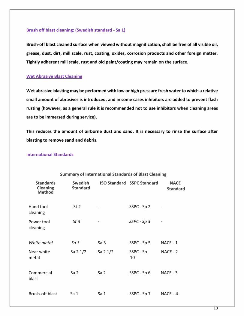
International Standards
Summary of International Standards of Blast Cleaning
Standards Cleaning Method
Swedish Standard
ISO Standard SSPC Standard NACE Standard
Hand tool cleaning
Power tool cleaning
St 2 - SSPC - Sp 2 - St 3 - SSPC - Sp 3 -
White metal Sa 3 Sa 3 SSPC - Sp 5 NACE - 1
Near white metal
Sa 2 1/2 Sa 2 1/2 SSPC - Sp 10
NACE - 2
Commercial blast
Sa 2 Sa 2 SSPC - Sp 6 NACE - 3
Brush-off blast Sa 1 Sa 1 SSPC - Sp 7 NACE - 4
14
The standards given above give a visual impression of the quality of the de-rusted steel.
However, invisible contamination like soluble salts should also be absent. This should be checked
by measuring the conductivity of water that has been used to wash a certain small area of a (blast)
cleaned surface.
All standards of cleaning steel are based only on the cleanliness of the surface. When steel is
polished and clean (having no anchor pattern) it is also Sa 2½ or Sa 3. Therefore, Sa 2½ or Sa 3 is
not an indication of roughness. With all sorts of abrasives the grade Sa 2½ is reachable.
But each type of abrasive and the speed at which it makes contact with the steel gives a different
anchor pattern.
As per ISO 8501-01, the initial condition of steel is given by the rust grades as given below:
A =Steel covered completely with adherent mill scale and with, if any, little rust.
B =Steel surface which has begun to rust and from which the mill scale has begun to flake.
C =Steel surface on which the mill scale has rusted away or from which it can be scrapped but
with little pitting visible to the naked eye.
D =Steel surface on which the mill scale has rusted away and on which considerable pitting is
visible to the naked eye.
For further details, please refer the specified standards.
15
3.3 Surface Profile
In addition to the cleaning requirement, a surface also must have sufficient profile (anchor pattern or tooth) to permit bonding of the primer. Abrasive blasting of steel generally provides an irregular profile, while mechanical tools frequently provide a burnished surface.
Surface profile indicates the roughness of blast cleaned surface. 'Surface profile is an independent factor' and it has no relation to the standard of cleanliness. The profile of roughness obtained during blasting is important and will depend upon the abrasive media, the air pressure, and technique of blasting. To specify the roughness, a variety of values are used, such as Rz, Rt, Ra, C.L.A. Rz = average peak to valley height = blasting profile Rt = maximum peak to valley height Ra = average distance to an imaginary center line which can be drawn between peaks and valleys C.L.A. [Center line Average (ISO : 3274)] Blasting Profile (Rz) = 4 to 6 times C.L.A. (Ra)
Generally the profile height of steel should be in between 1/2 and 2.5 mils and not more
than one third of the total dry film thickness of the coating system.
Too high a profile will result in uneven coverage of high sharp peaks possibly leading to
premature coating failure. Too low a profile may not provide a sufficient key of coating.
For some product a minimum surface profile is mandatory as indicated in our product
data sheet.
3.4 Surface Preparation - Non-Ferrous Substrate
Surface should be dry and clean. Any visible oil/grease should be removed. Cleaned surface should be abraded or sweep blasted using low pressure and non - metallic abrasives, then primed with a coat of etch primer.
Galvanized Steel
Degreasing to remove any oil/grease. Any white zinc corrosion products should be
removed by high pressure fresh water washing or fresh water washing with scrubbing.
Even if sweep blasting is done, water-washing is recommended to ensure removal of
soluble zinc salts.
Stainless Steel
Stainless steel surface does not require any specialized surface pretreatment prior to coating. These surfaces should be free from oil, grease, dirt and other foreign materials
16
by chemical cleaning. The development of a surface profile on stainless steel is highly recommended to assure good coating adhesion. A profile depth of between 1.5 and 3.0 mils is suggested for most coating systems. Because stainless steel is a very hard metal, abrasive blasting is recommended to impart a continuous surface profile.
Concrete Surface
New concrete or masonry:
Must be allowed to cure at least 30 days before coating. The moisture content of the concrete/masonry should be less than 6%. In case of large areas and for severe exposure conditions, the surface has to be prepared by light blasting. In less critical areas where blasting is not practical, wire brushing has to be adopted to remove laitance, followed by treating with dilute hydrochloric acid (10%).
Old concrete surface:
Remove the surface contaminants like grease, oil, etc., by solvent wiping or by 10% caustic solution. Preferably the surface has to be prepared by light blasting. In case, blasting is not practical, etch the surface to get a good profile by treating white dilute hydrochloric acid (10%). Remove acid and contaminants by liberal wash with water. Ensure that acid solution does not retain on the surface and joints. Allow the surface to dry thoroughly before applying primer. Any cracks should be cut out and filled with suitable filler prior to painting.
3.5 Paint Application
3.5.1 Application - Brush
Brushing is the most common method for applying coatings. While brushing is a somewhat slow procedure many small jobs do not warrant the use of any other application method. Brushing is especially useful for touch up work, spot priming, work in confined areas or where spraying is impossible. Less paint is wasted when applied by brush than by any other method. Either natural or synthetic bristle brushes are suitable for use with "solvent based" coatings. Synthetic bristle brushes are preferred with "water based" coatings because natural bristles tend to swell in water. Suggestions for good brush application:
Use of high quality, clean brushes of the proper shape and size will help achieve the best application.
Assure that all holidays or voids are eliminated, but avoid excessive brushing which may reduce film thickness and decrease protection.
17
Avoid filling the heel of the brush with material. Approximately half of the bristle length of the brush should be wet.
Stroke the brush at 45° angle. Light strokes at this angle ensure even flow.
The brush application shall be by up and down strokes, then crosswise and finally with up and down strokes lightly. This is called cross lapping and helps eliminate brush and lap marks. Fast drying materials often do not permit cross lapping which may cause paint to pile up. If it is necessary to brush apply fast dry material, it should be flowed on rapidly and generously and then left undisturbed. To go back over such a surface usually results in excessive brush drag, leaving ridges and brush marks.
3.5.2 Application - Roller
Rollers are efficient tools for applying industrial coatings and are suited for broad flat surfaces. The general rule for selecting a roller cover is 'the smoother the surface the shorter the nap'. Solvent thinned coatings should be applied with either lamb's wool or synthetic covers and water reduced coatings should be applied with synthetic covers. When using rollers to apply coating systems such as epoxies and polyurethanes which contain strong solvents, be sure that the roller cover selected is constructed with glues which are resistant to these strong solvents. Suggestions for effective roller application:
On large areas, material should be applied approximately on 0.75 sq.m. at a time.
Saturate the roller cover thoroughly with the coating. Paint should be loaded onto the cover until just before it drips.
The first strokes with the loaded roller should be done in a "W" pattern within approximately 0.75 sq.m. area.
The "W" pattern should then be fixed in with successive strokes.
Work from dry areas back into wet areas. In this way a more uniform film thickness is maintained.
When a material is applied to warm surfaces in direct sunlight or when fast drying coatings are used, work in smaller areas to maintain a wet edge.
Most coatings will dry to a slight orange peel appearance when applied by rollers.
3.5.3 Application - Spray
Introduction
The easiest and most rapid method for the application of protective coatings to large areas is spraying. Spray application is preferred where a smooth uniform finish is desired and speed of production is important. Conventional air atomization is used when quality of finish is of utmost importance or where great versatility is desired. Airless spray is best for large scale operations not requiring very fine finish.
18
Both conventional and airless spray may be modified for increased performance or for specialized applications. One such modification includes adding heaters to fluid lines. The use of heated paint permits atomization at lower pressures, decreases or eliminates the need for thinning, cuts down an overspray rebound and provides a heavier film build with minimum waste of paint and solvents. The only drawback associated with hot spraying is that the pot life of catalyzed products sprayed by heated method is generally reduced.
Air Spray Application
A conventional air spray gun is a precision tool which uses compressed air to atomize sprayable materials. Air and paint enter the gun through separate passages and are mixed and ejected at the air nozzle to provide a controlled spray pattern. The amount of paint leaving the gun is controlled by the pressure on the fluid container, the viscosity of the paint, the size of the fluid orifice, and by the fluid needle adjustment. Suggestions for effective air spray painting: • Use the lowest possible air and fluid pressure when operating a spray gun. • Use the proper fan width for the job. • Spray from the proper distance (6-10 inches). • Hold the gun perpendicular to the work throughout the spray stroke. • Move the spray gun parallel to the work surface throughout the spray stroke. • Move the spray gun at a speed which assures that a full wet coat is applied to the surface. • Overlap strokes at least 50%.
Airless Spray Application
Airless spray is a method of application which does not directly use compressed air to atomize the coating sprayed. Hydraulic pressure is used to atomize the fluid by pumping it at high pressures (500-3500 p.s.i.) through a small precision orifice in a spray nozzle. As the fluid is released at these high pressures, it is separated into small droplets resulting in a finely atomized spray. Since air is not used to form the spray pattern, the term "airless" is used to describe this method. Airless spray painting is cleaner and faster than conventional spraying methods. One advantage of airless spraying is that the overspray fog or rebound associated with conventional spray is greatly reduced. This makes use of equipment possible in places and applications where material formerly had to be brushed. Another significant advantage of airless spray is the ability to apply heavy coating thickness more quickly than by any other method. Most coating materials may be sprayed in their unthinned state which also helps contribute towards the formation of heavy films and greatly reduces thinner use.
19
Suggestions for effective airless spray painting: The technique employed for airless spraying is similar to the technique practiced in air spraying.
The ideal spraying pressure for any given tip is achieved by gradually increasing
the pressure until the spray pattern appears uniform across its fan width and
the atomized coating particles are of acceptable size.
If the coating is coarsely atomized, the pressure may be increased slightly, a
smaller orifice tip used, or the coating thinned.
Avoid using excessively high airless spray pressures, which may cause
effervescence or other finish defects.
Hold the gun perpendicular and move it parallel to the surface at all times in
order to obtain a uniform coating of material.
Arcing, heeling and toeing should be avoided at all times.
The proper working distance with airless spray is approximately 10-15 inches.
When using wide angle spray tips, the gun must be moved closer
(approximately 10-12 inches) to the work.
Excessive spray distances increase paint fog and paint consumption.
Technique of spray application
Coating should be even and wet when spraying
3.5.4 Directions of Use
Air drying epoxy and polyurethane coatings are normally two component systems, consisting of a base and a hardener. The two components have to be mixed in the ratio recommended to ensure proper and complete curing of the coatings. Improper ratio leads to problems like soft/non-dried film, poor performance, etc. The base and hardener are to be separately mixed first to obtain a homogenous mixture. The hardener is to be added to the base slowly, with continuous mixing/agitation and not the reverse. After complete addition, mixing/agitation is to be continued to achieve a homogenous mixture. Power agitation in preferred over hand mixing. Any addition of thinner to achieve the application viscosity should be made only after the components are thoroughly mixed and not to the base/hardener or while mixing the two components. After thorough mixing of the product, the maturation time as indicated in the product data sheet is to be allowed before applying the product. The mixture thickens as the time progresses, and at the end of the pot life period the mixture becomes highly viscous and unusable. It is best to consume mixed paint at least one hour before the end of the pot life.
20
Avoid using excess thinner than the recommended volumes, since this can lead to lower dft buildup, sagging, longer curing time, etc.
3.5.6 Directives for Ventilation Practice
Adequate ventilation is necessary for the safety as well the quality of the coating system. The amount and type of residual solvent in the coating can be detrimental to performance of coating, as it can affect adhesion, water resistance, mechanical and chemical properties. Very slow evaporation of trapped solvents can also develop internal stress due to shrinkage. The ventilation must be maintained throughout the application process and also for a period after application is completed. Ventilation air should be directed to the base of the tank or compartment and should also be extracted by exhaust fans of correct balance capacity.
3.6 Guideline for Application of IZS
Surface Preparation
Remove oil, grease and other contamination with a suitable detergent,
followed by high pressure water washing. Aromatic solvents can also be used
to remove the contaminants.
Ensure that all welds/weld seams are complete and continuous without any
cracks and pinholes. Remove all weld spatters & round off all the sharp edges
prior to further surface preparation. In case you find any traces of soap/alkali
deposits on weld joints which are used for pressure testing, please remove the
same by fresh water washing and scrubbing with stiff nylon brushes.
After above operation, grit blast to Sa 2 ½ to Sa 3 of Swedish specification. For
severe exposure conditions, grit blasting to Sa 3 is recommended for optimum
results. The surface profile after blast cleaning shall be 50 -
75 microns.
Substrate temperature should be at least 3°C above dew point but not above
50°C.
Relative humidity should be above 50%.
Note:
Use steel grits, aluminium oxide grits or similar sharp edged abrasives, free of foreign matters and soluble salts.
Steel grit with particle size of 0.2 - 1.0 mm or aluminium oxide of 0.4 - 1.8 mm should generally help to achieve the surface profile of 50 - 75 microns with 100 p.s.i. air pressure.
21
Application
Inorganic zinc silicate coatings should be applied by spray application only. Brush application can be used only for touch-up areas.
Air Spray:
Nozzle pressure- 43 - 57 p.s.i. Nozzle orifice - 1.8 - 2.2 mm Volume of thinner - 10 - 25 %
Airless Spray:
Nozzle pressure - 1700 - 2100 p.s.i. Nozzle orifice - 0.48 - 0.64 mm Volume of thinner - 10 - 25 %
Note:
Pressure pot must be fitted with an air driven agitator to maintain continuous mixing while application.
The fluid hose should not be more than 15 meters long.
Use specified thinner as given in the data sheet for thinning and cleaning.
Apart from correct spray technique, the amount of thinner should be adjusted in such a way that the coating applied is wet and smooth just after application.
The amount of thinner will depend upon site conditions such as temperature, humidity, wind flow, ventilation etc.
Select small nozzles for spray application of complicated and non regular structures.
Mixing of Paint
Stir/shake the hydrolysate part thoroughly before mixing. The powder portion (zinc dust) should be added to the hydrolysate component slowly with constant mechanical stirring. Continue stirring until the mixed paint is free from lumps.
Filter the mixture through a wire screen of 30-60 mesh. Keep the mixture continuously stirred during application and ensure that it is used within 4 hours.
Avoid part mixing of the paint.
22
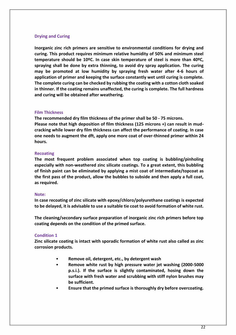
Drying and Curing Inorganic zinc rich primers are sensitive to environmental conditions for drying and curing. This product requires minimum relative humidity of 50% and minimum steel temperature should be 10ºC. In case skin temperature of steel is more than 40ºC, spraying shall be done by extra thinning, to avoid dry spray application. The curing may be promoted at low humidity by spraying fresh water after 4-6 hours of application of primer and keeping the surface constantly wet until curing is complete. The complete curing can be checked by rubbing the coating with a cotton cloth soaked in thinner. If the coating remains unaffected, the curing is complete. The full hardness and curing will be obtained after weathering. Film Thickness The recommended dry film thickness of the primer shall be 50 - 75 microns. Please note that high deposition of film thickness (125 microns +) can result in mud-cracking while lower dry film thickness can affect the performance of coating. In case one needs to augment the dft, apply one more coat of over-thinned primer within 24 hours. Recoating The most frequent problem associated when top coating is bubbling/pinholing especially with non-weathered zinc silicate coatings. To a great extent, this bubbling of finish paint can be eliminated by applying a mist coat of intermediate/topcoat as the first pass of the product, allow the bubbles to subside and then apply a full coat, as required. Note: In case recoating of zinc silicate with epoxy/chloro/polyurethane coatings is expected to be delayed, it is advisable to use a suitable tie coat to avoid formation of white rust. The cleaning/secondary surface preparation of inorganic zinc rich primers before top coating depends on the condition of the primed surface. Condition 1 Zinc silicate coating is intact with sporadic formation of white rust also called as zinc corrosion products.
• Remove oil, detergent, etc., by detergent wash • Remove white rust by high pressure water jet washing (2000-5000
p.s.i.). If the surface is slightly contaminated, hosing down the surface with fresh water and scrubbing with stiff nylon brushes may be sufficient.
• Ensure that the primed surface is thoroughly dry before overcoating.
23
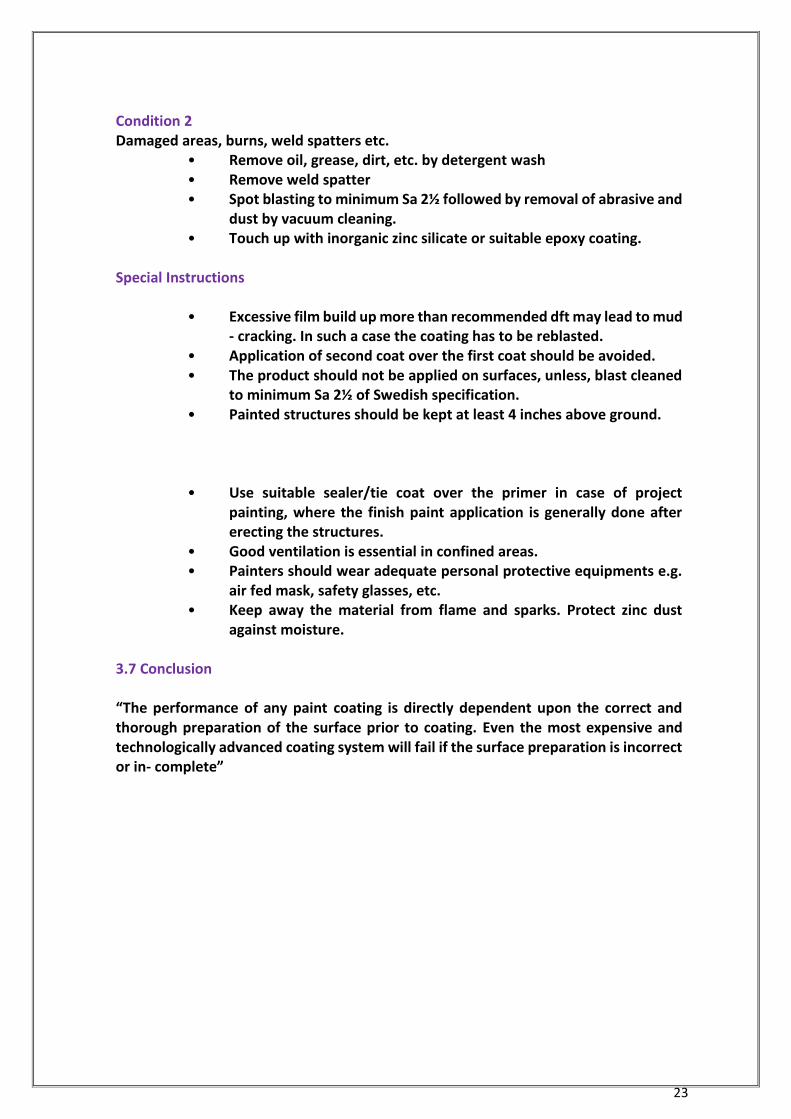
Condition 2 Damaged areas, burns, weld spatters etc.
• Remove oil, grease, dirt, etc. by detergent wash • Remove weld spatter • Spot blasting to minimum Sa 2½ followed by removal of abrasive and
dust by vacuum cleaning. • Touch up with inorganic zinc silicate or suitable epoxy coating.
Special Instructions
• Excessive film build up more than recommended dft may lead to mud - cracking. In such a case the coating has to be reblasted.
• Application of second coat over the first coat should be avoided. • The product should not be applied on surfaces, unless, blast cleaned
to minimum Sa 2½ of Swedish specification. • Painted structures should be kept at least 4 inches above ground.
• Use suitable sealer/tie coat over the primer in case of project painting, where the finish paint application is generally done after erecting the structures.
• Good ventilation is essential in confined areas. • Painters should wear adequate personal protective equipments e.g.
air fed mask, safety glasses, etc. • Keep away the material from flame and sparks. Protect zinc dust
against moisture.
3.7 Conclusion “The performance of any paint coating is directly dependent upon the correct and thorough preparation of the surface prior to coating. Even the most expensive and technologically advanced coating system will fail if the surface preparation is incorrect or in complete”
24
Chapter 4 Coating Application Types and Technologies
There are about a dozen different ways to apply paint. Each one in uniquely suited to a
particular job. This section gives an overview of several types of industrial plant
application methods and their strengths and weaknesses.
Besides the “conventional” method of applying coatings, many choices exist for
someone who is involved in painting or coating operations. The right choice for you
depends on your particular business operations—the type of pieces you coat; the
finished appearance requested by customers; money available for equipment, training,
and maintenance costs; and even how much room you have in your business.
The following are summaries of some available technologies.
4.1 Low-Volume High –Pressure (LVHP)
Low-volume high-pressure spray (LVHP) is considered the conventional method of
applying coatings. It depends on air-atomizing the paint at pressures of 40–70 pounds
per square inch (psi). Air is supplied from an air compressor or turbine. While these spray
systems create high quality finishes at high production rates, they do have several
disadvantages, including extensive overspray, increased booth cleanup costs, and
increased filter use and related costs. Additionally, if a higher coating thickness is
necessary, more operator passes may be necessary to get the desired mil thickness, and
hence application time is increased.
4.2 High-Volume Low –Pressure (HVLP)
The principle of high-volume low-pressure (HVLP) has been applied to “conventional”
spray guns to apply paint with a high volume of dispersing air at low pressures. HVLP
guns have nozzles with larger diameter openings for atomizing air, can be bleeder or
non-bleeder types, and require air volumes of 10–30 cubic feet per minute. Air and fluid
delivery to the spray gun affect the efficiency, ease of use, cost, and versatility of HVLP
sprayers.
25
In a siphon-fed HVLP system, air pressure to the sprayer is used to pull paint from the
cup located below the gun, producing a fully atomized pattern for even surface
coverage. Gravity-fed HVLP systems are well adapted for higher viscosity paints, such as
clears, water-based paints, high-solids paints, and epoxy primers, given the paint cup
location. The cup, located at the top of the gun, allows paint to completely drain,
minimizing paint waste.
HVLP guns allow operators to finish intricate parts with comparable quality to
conventional sprayers. This makes them a good choice for small shops that finish
smaller, more intricate parts which demand a higher level of gun control. Other
advantages of the HVLP system include the following:
Transfer efficiencies, from 50 to 90 percent reported, depending on the air-
delivery system used
Reduced amount of overspray, and hence material use
Reduced VOC and HAP emissions
Reduced paint booth filter use and cleanup costs
Reduced worker exposure due to high-pressure “blowback” from the spray
Good coverage of intricate parts
Finish quality comparable to conventional air sprayers
Comparable transfer efficiencies to air-assisted airless sprayers at low-fluid
delivery rates, with low to medium viscosity fluids
More efficient air atomization
Air-spray coating adaptable to any size coating operation and application rate
Equipment fittings allow for fast color changes and application of very different
fluid viscosities
HVLP systems, however, do have some disadvantages, including difficulty in obtaining
higher fluid delivery rates with high viscosity materials, and a lack of sufficient
atomization required for some fine finishes.
26
4.3 Air spray
The air spray gun uses air at 30 to 85 pounds per square inch (psi) to atomize the paint
into a fine spray. This produces a smoother finish, and can be used on many surfaces. Air
spraying is versatile; the operator can vary the air pressure, air volume, paint pressure,
and spray pattern. It is much faster than painting by hand unless a lot of masking is
required for the job. But air spraying does produce a lot of overspray (the paint that
misses the intended target), and preparation and clean-up take more time.
A High Volume Low Pressure (HVLP) spray gun uses a higher volume of air at only 10 psi.
This reduces the overspray and increases the transfer efficiency. It is portable and easy
to clean, and has a lower risk of blowback to the worker. However, the atomization may
not be good enough for fine finishes, and production rates when using HVLP may not be
as high as with conventional spraying.
4.4 Airless Spray
This method uses paint under high pressure, 500 to 6,500 psi. Airless spraying has several
distinct advantages over air spray–it is twice as fast, produces a higher film build, is more
portable, cuts overspray by more than half, and is thus cleaner and more economical.
But airless spray is limited to painting large areas, requires a different nozzle to change
spray patterns, the nozzle tends to clog, and the nozzle can be dangerous to use or to
clean because of the high pressures involved.
4.5 Electrostatic Spraying
The differences between this and air spraying are that the electrostatic gun has an
electrode at the nozzle and the object to be painted is grounded. The electrode runs
60,000 volts through the paint at 225 microamperes. The charged paint is attracted to
the grounded object. This requires less pressure, produces little overspray, and uses
relatively little paint. Electrostatic guns are good for painting oddly shaped objects. They
also produce a uniform coat because the paint itself acts as an insulator; once the object
is covered, it can take no more paint.
27
The disadvantages are: only one coat is possible, only conductive materials can be
painted; it’s more expensive, slower, has higher maintenance costs, is limited to
chargeable paints, and the surface of the object must be extremely clean. Because the
gun uses electricity, this method presents a possible shock hazard.
4.6 Powder Coating
This is a variation of electrostatic spraying. The difference is that what is sprayed is a
paint powder. The object is then bake, and the powder melts into a smooth, durable
coat. Overspray can be reused, and no other pollutants are created or released because
the powder has no solvents in it. The equipment for powder coating is expensive, so it
may be economical for only larger businesses. A variation of this is plasma powder
coating. The powder is fed into an extremely hot gas stream and is then sprayed at the
object. Plasma powder coating is for large objects that can’t fit into a conventional curing
oven. Overspray cannot be reused because it hardens.
Another variation is flame sprayed powder coating, where the powder is melted with a
high temperature flame. Again, it is for large objects and overspray cannot be reused.
4.7 Rotary Atomizing
Another variation of electrostatic painting, rotary atomizers use centrifugal force, not
air or hydraulic pressure, to drive the paint out of the nozzle. The atomization of this
method is excellent, as is the transfer efficiency. This method can also be used with
paints of different viscosity. Cleanliness is especially important to this method. Rotary
atomizers can present a fire and safety hazard.
4.8 Dip Coating
With this process, parts are dipped into a vat of paint. This allows for a high production
rate and transfer efficiency, and it requires relatively little labor. The effectiveness of dip
coating depends greatly on the viscosity of the paint, which thickens with exposure to
air unless carefully managed. Dip coating is not suitable for objects with hollows or
cavities, and generally the finish is of lower quality.
28
4.9 Flow Coating
With this method, parts are carried on a conveyor. Anywhere from 10 to 80 streams of
paint coat the parts. This system has the advantages of dip coating, along with low
installation costs and low maintenance requirements. The quality of the finish is also
about as good as with dip coatings.
4.10 Curtain Coating
Instead of many streams of paint, curtain coating uses a waterfall flow of paint to coat
parts on a conveyor belt. Curtain coating has a high transfer efficiency and covers parts
uniformly, but is suitable only for flat work. The quality of the finish is highly dependent
on the viscosity of the paint.
4.11 Roll Coating
Paint is applied to auxiliary rollers, which then transfer the paint to the application
rollers, which run across the part. This method has a high transfer efficiency and high
production rates, but is limited to flat work.
4.12 Electro coating (or Electrode position)
Parts to be painted are dipped into the paint. Then a current is applied, which electrically
deposits the paint on the object. Parts are made primarily of steel. The transfer efficiency
of electro coating is over 90%. High production rates are possible, and production can
be automated. However, this method is costly and requires a lot of energy. Also,
employees need high level training to use this system.
4.13 Auto deposition
This is a dip process where organic paints are precipitated onto iron, steel, zinc and zinc-
alloy plated objects. It is effective for its anti-corrosion properties and coverage of
objects. Auto deposition also uses water-borne paints and uses no electricity. But auto
deposition produces a dull or low gloss finish and has few available colors.
[For further information visit www.hazard.uiue.edu/wmr]
29
Chapter 5 Comparison of Coatings
5.1 Introduction
Traditionally, paint has been considered a liquid made up of several components that
when applied and cured impart a thin plastic film. Paints have traditionally been organic
solvent-based, with the solvents aiding in the application process. While being versatile,
it has many environmental issues associated with its use, including air emissions and
hazardous waste disposal. High-solids paints have a higher percentage of paint solids
and contain less solvent, and while air emissions may be less, they are still present.
Water based paints, which utilize water as the solvent, also have reduced VOC
emissions, as well as a reduced fire hazard. “Solid paints,” such as powder coatings and
paints containing no solvents (and hence have reduced HAP and VOC emissions), are
widely available. These materials have given rise to the term “coatings” instead of
paints. With catalyzed or two-component coating systems, reactive resins and catalysts
are mixed just before entering the application equipment. This type of coating system
can also reduce solvent use.
The following provides a comparison of four different coating technologies
5.1.1 High-solids Coatings (where the paint was modified to produce a coating with
higher solids concentration and a lower VOC concentration)
Pollution prevention benefits:
Reduces solvent in coatings
Less overspray compared to conventional coatings
Higher transfer efficiencies
Operational benefits:
Can apply thick or thin coat
Easy color blending or changing
Compatible with conventional and electrostatic application equipment
Energy savings:
Reduced air flow in work spaces and curing ovens (low VOC)
Reduced energy needed for heating makeup air
30
Applications:
Zinc-coated steel doors
Miscellaneous metal parts
Same as conventional coatings
Limitations:
Solvent use not completely eliminated
Shorter pot life than conventional coatings
5.1.2 Water- Based Coatings (which mainly use water to disperse the paint resin,
although some solvent is still present)
Pollution prevention benefits:
Eliminates or reduces solvent in coatings
Reduced VOC emissions and fire hazards
Reduced hazardous waste disposal
Water used for cleanup
Operational benefits:
Can apply thick or thin coat
Easy color blending or changing
Compatible with conventional and electrostatic application equipment
Energy savings:
Reduced air flow in work spaces (little or no VOC)
Reduced energy needed for heating makeup air
Applications:
wide range
Architectural trade finishers
Wood furniture
Damp concrete
Limitations:
Coating flow properties and drying rates can change with humidity, affecting
coating application
Sensitive to humidity, workplace humidity control required

31
May have poor flow characteristics due to high surface tension of water
Special equipment needed for electrostatic application
Water in paint can cause corrosion of storage tanks and transfer piping, and
“flash rusting” of metal substrates
5.1.3 Powder Coatings (which have become a viable alternative for decorative and
functional coatings, although still predominately a metal-finishing process)
Pollution prevention benefits:
Eliminates solvent in coatings
Little or no VOC emissions
Easier to recycle and reuse over-spray
Reduces solvents for cleaning
Reduces need for solid paint waste disposal
Operational benefits:
Can apply thick coat in one application
No mixing or stirring
Efficient material use, possible to achieve nearly 100% transfer efficiency if a
reclaim system is used
Energy savings:
Little air flow needed for worker protection (no VOC)
Little energy needed for heating makeup air
Applications:
Steel
Aluminum
Zinc and brass castings
Limitations:
Requires handling of heated parts
Part must be electrically conductive, complex shapes difficult to coat
Difficult to apply thinner coatings
Need special equipment or extra effort to make color changes
Difficult to incorporate metal flake pigments
32
5.1.4 UV-cured coatings (coatings requiring UV radiation to initiate crosslinking of the
resin).
Pollution prevention benefits:
Eliminates solvent in coating
Allows for increased production rates
100% reactive liquid
Operational benefits:
Can apply thin coats
Easy color blending or changing
Efficient material use, nearly 100% transfer efficiency
Energy savings:
Little air flow in work spaces (no VOC)
Cure with UV instead of an oven
Little energy needed for heating makeup air
Applications:
Some metal applications
Filler for chipboard
Wood
“Wet look” finishes
Limitations:
Styrene volatility
Typically best applied to flat materials
Limited to thin coatings
High capital cost of equipment
Yellow color
33
Chapter 6 Paint Trouble Shooting – Paint Problems and Solutions
6.1 Introduction
Paint Problems are easy to spot, but in many cases quite difficult to analyze. This section
is prepared to assist applicators. The section contains information and advice from
experienced users and applicators, technicians, and product developers.
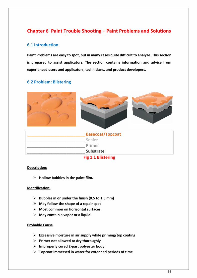
6.2 Problem: Blistering
_________________________ Basecoat/Topcoat _________________________ Sealer _________________________ Primer _________________________ Substrate
Fig 1.1 Blistering
Description:
Hollow bubbles in the paint film.
Identification:
Bubbles in or under the finish (0.5 to 1.5 mm)
May follow the shape of a repair spot
Most common on horizontal surfaces
May contain a vapor or a liquid
Probable Cause
Excessive moisture in air supply while priming/top coating
Primer not allowed to dry thoroughly
Improperly cured 2-part polyester body
Topcoat immersed in water for extended periods of time
34
Remedy
Check for moisture damage
Use recommended epoxy fillers
Apply primer/sealer
Repaint
Prevention
Allow sufficient drying times
Use EP-2C Hi-Build Epoxy Primer (waterproof at 12.0 mil) in high moisture
conditions
Cover painted articles for long term storage with a non-airtight cover
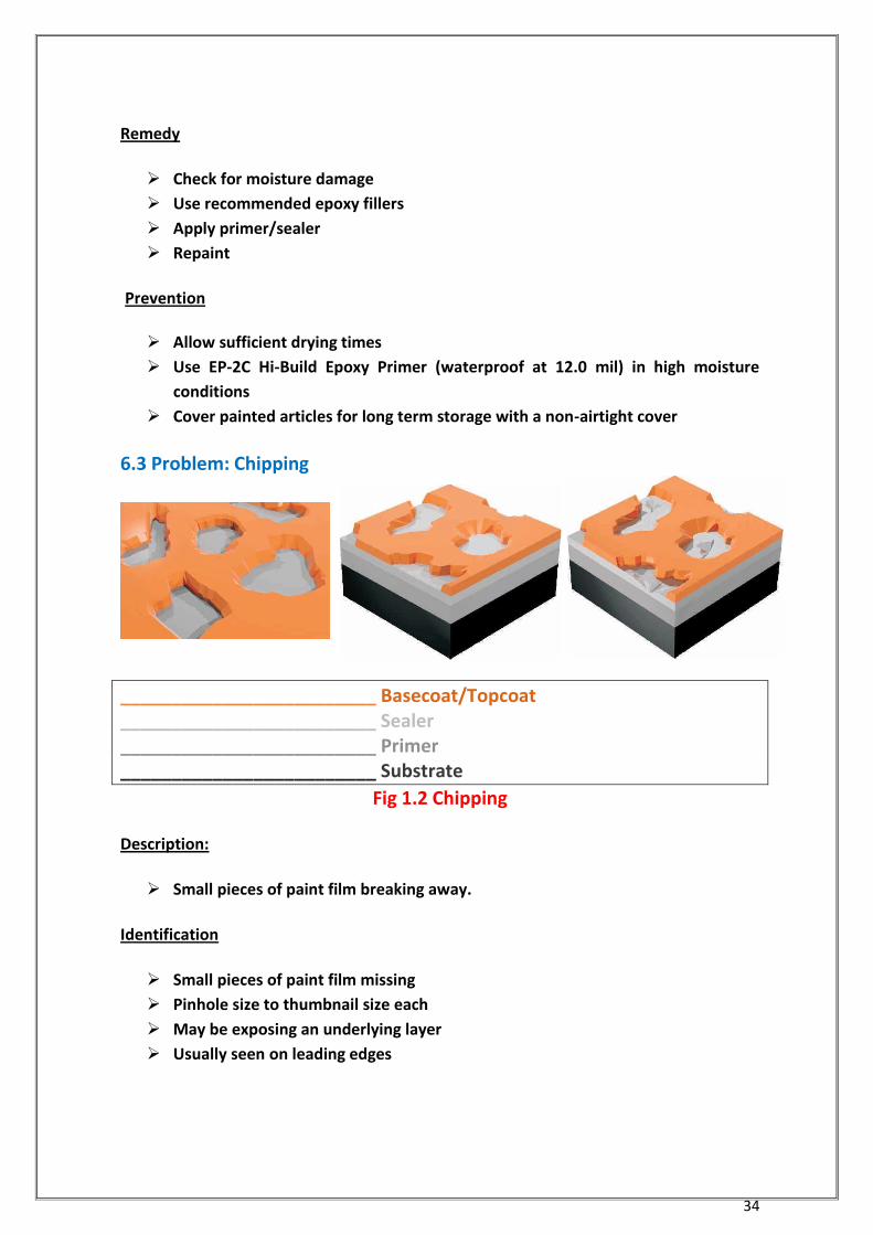
6.3 Problem: Chipping
_________________________ Basecoat/Topcoat _________________________ Sealer _________________________ Primer _________________________ Substrate
Fig 1.2 Chipping
Description:
Small pieces of paint film breaking away.
Identification
Small pieces of paint film missing
Pinhole size to thumbnail size each
May be exposing an underlying layer
Usually seen on leading edges
35
Probable Cause
Surface impact
Using HS-421 Primer without sealing before applying topcoat
Exposure to harsh conditions- Frequent use on gravel roads
Remedy
Small chips can be filled with 2-part
Large chips or large areas with chipping should be blended - follow proper
Blending Procedure
Select the most suitable coatings for environmental conditions
Repeat all steps in application procedure
Prevention
Avoid use of HS-421 Primer in high impact areas
Use EP-321 Epoxy Primer or EP-521
Epoxy Primer for industrial service (sandblasted steel, etc.)
Use EX-2C TF-2K Topcoat for severe conditions
6.4 Problem:
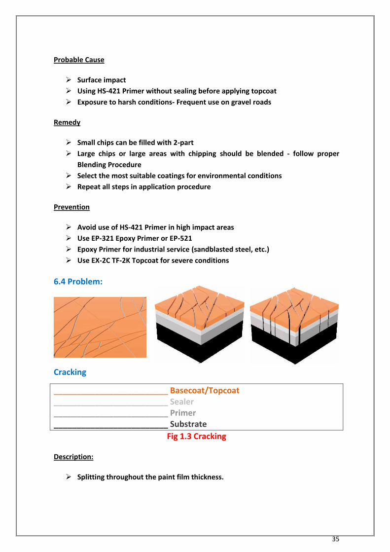
Cracking
_________________________ Basecoat/Topcoat _________________________ Sealer _________________________ Primer _________________________ Substrate
Fig 1.3 Cracking
Description:
Splitting throughout the paint film thickness.
36
Identification
Topcoat splitting
Series of straight lines
Primer or substrate may be visible
Probable Cause
Substrate not at room temperature
Component “A” and Component “B” not uniformly mixed
Coating applied over a previously cracked finish or unstable substrate Excessive
total film thickness
Remedy
Remove finish from affected area
Apply primer/sealer
Repaint
Prevention
Remove poor quality/unstable finishes Check current film thickness before
starting. Excessive paint should be removed before refinishing.
Mix Component “A” and Component “B” thoroughly
Follow recommended film thickness
Follow recommended flash-off and drying time between coats
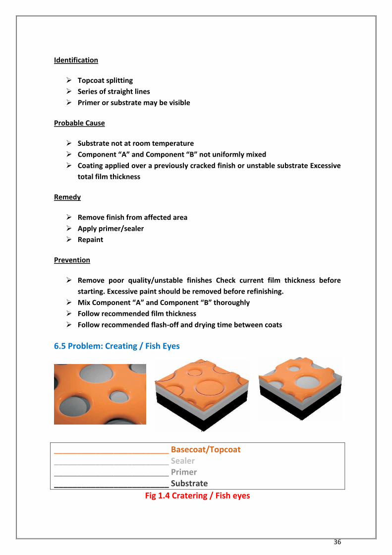
6.5 Problem: Creating / Fish Eyes
_________________________ Basecoat/Topcoat _________________________ Sealer _________________________ Primer _________________________ Substrate
Fig 1.4 Cratering / Fish eyes
37
Description:
Usually occurs while spraying or immediately after.
Paint film marked with round surface depressions or bowl-like craters.
Identification
Usually sporadic, confined to specific contaminated areas
Previous coat is visible
The centre may contain a particle
Probable Cause
Surface contamination:
- Silicone or wax based protective coatings or polishes
- Hand prints - Grease, oil, diesel fuel - Wash solvents containing naphtha
Contaminated booth air intake
Insufficiently dried surface contaminated in shop/drying area
Continual use of proper Crater Eliminator
Remedy
If noticed while painting:
- Stop painting
- Allow flash-off
- Re-mix coating, adding more EX-2C Thinner:
1 part Component “A”
1 part Component “B”
2 parts EX-2C Thinner
Continue to paint subsequent coats at the normal mix ratio
Major problem:
- Allow to dry thoroughly
- Determine and remove the contaminant
- Sand smooth
- Clean substrate thoroughly with soap and water
- Repaint
Prevention
Proper surface preparation: use water-based cleaning solutions
Ensure compressed air is not contaminated with oil and water Protect against
diesel exhaust fumes and other air-borne contaminants
Maintain a clean shop
Use recommended amounts of proper Crater Eliminator
38
Mist on the 1st coat of topcoat
Allow booth exhaust fan to run as long as possible
Provide a clean working area
Wear clean protective equipment including latex or nitrile gloves
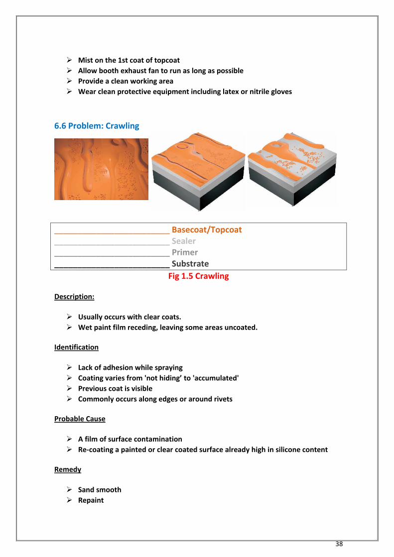
6.6 Problem: Crawling
_________________________ Basecoat/Topcoat _________________________ Sealer _________________________ Primer _________________________ Substrate
Fig 1.5 Crawling
Description:
Usually occurs with clear coats.
Wet paint film receding, leaving some areas uncoated.
Identification
Lack of adhesion while spraying
Coating varies from 'not hiding’ to 'accumulated'
Previous coat is visible
Commonly occurs along edges or around rivets
Probable Cause
A film of surface contamination
Re-coating a painted or clear coated surface already high in silicone content
Remedy
Sand smooth
Repaint
39
Prevention
Proper surface preparation: use water- based cleaning solutions
Frequently replace tack cloths and rags used to solvent wipe
Pay special attention wiping edges and problem areas
Reduce product for the first coat of topcoat
Mist on the first coat of topcoat
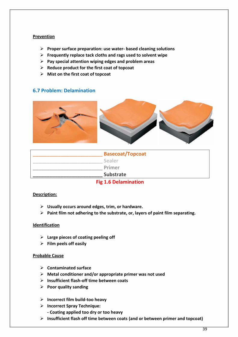
6.7 Problem: Delamination
_________________________ Basecoat/Topcoat _________________________ Sealer _________________________ Primer _________________________ Substrate
Fig 1.6 Delamination
Description:
Usually occurs around edges, trim, or hardware.
Paint film not adhering to the substrate, or, layers of paint film separating.
Identification
Large pieces of coating peeling off
Film peels off easily
Probable Cause
Contaminated surface
Metal conditioner and/or appropriate primer was not used
Insufficient flash-off time between coats
Poor quality sanding
Incorrect film build-too heavy
Incorrect Spray Technique:
- Coating applied too dry or too heavy
Insufficient flash off time between coats (and or between primer and topcoat)
40
Remedy
Featheredge the problem areas Use sealer as recommended Repaint
Reduce total film thickness
Prevention
Follow recommended topcoat window Follow recommended film builds, topcoat
will delaminate if applied over an insufficient primer coat
Follow recommended viscosity Follow recommended flash-off times
Carefully sand edges and areas around hardware
Use recommended metal conditioner and conversion coating
Clean thoroughly with recommended water-based cleaners
Mix Component “A” and Component “B” thoroughly
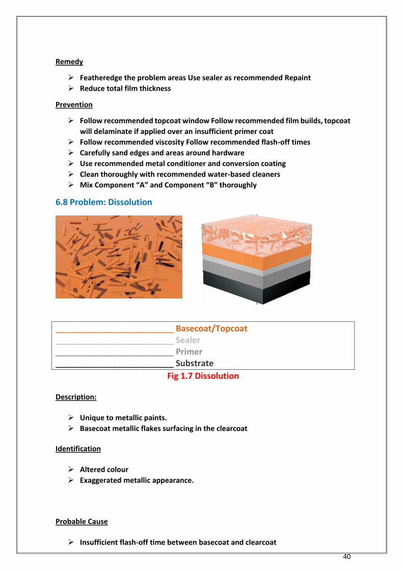
6.8 Problem: Dissolution
_________________________ Basecoat/Topcoat _________________________ Sealer _________________________ Primer _________________________ Substrate
Fig 1.7 Dissolution
Description:
Unique to metallic paints.
Basecoat metallic flakes surfacing in the clearcoat
Identification
Altered colour
Exaggerated metallic appearance.
Probable Cause
Insufficient flash-off time between basecoat and clearcoat
41
Remedy
Allow the paint to dry
Sand smooth
Repaint base and clear
Prevention
Correct gun set up
- use recommended air pressure
Use recommended amounts of paint by vendor
Super Catalyst II in the basecoat
Follow recommended flash-off times
Follow recommended viscosity
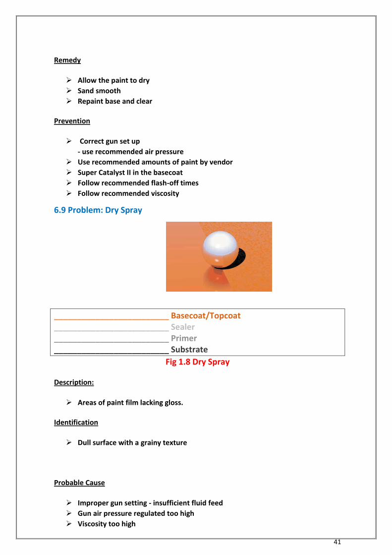
6.9 Problem: Dry Spray
_________________________ Basecoat/Topcoat _________________________ Sealer _________________________ Primer _________________________ Substrate
Fig 1.8 Dry Spray
Description:
Areas of paint film lacking gloss.
Identification
Dull surface with a grainy texture
Probable Cause
Improper gun setting - insufficient fluid feed
Gun air pressure regulated too high
Viscosity too high

42
Wrong thinner used - too fast
Incorrect spray technique:
- Holding spray gun too far from surface or passing too quickly resulting in an
insufficiently wet film
Remedy
Allow the paint to dry
Sand smooth
Repaint
Prevention
Only use repute manufacturers’ thinners/reducers, at recommended amounts
(up to 50% by volume, based on equipment used)
Use a slower thinner and retarder
Adjust gun set-up, fluid feed
- Follow recommended air Pressure
- Use larger size fluid tip
Alter spray technique, spray pattern
6.10 Problem: Mottling
_________________________ Basecoat/Topcoat _________________________ Sealer _________________________ Primer _________________________ Substrate
Fig 1.9 Mottling
Description:
Unique to metallic paints.
Concentrations of metallic flakes in the paint film.
Identification
A cloudy or blotchy appearance.

43
Probable Cause
Improper equipment: type of gun, size of nozzle
Improper gun settings
Incorrect spray technique:
- Holding spray gun too close to surface
- Uneven spray pattern
- Application too heavy
Wrong thinner/reducer for shop temperature
Component ''A'' and Component ''B'' not thoroughly mixed
Remedy
Sand smooth
Repaint
Prevention
Correct gun set-up:
- Decrease nozzle tip size
- Increase air pressure to provide more atomization
- Decrease fluid pressure in pressure pot
Proper selection of solvent for shop conditions
- In cold conditions use fast solvent
- In hot conditions use slow solvent
Use a Hi-Hide Basecoat followed by Clear 221
Use correct technique for applying
6.11 Problem: No Hold Out
_________________________ Basecoat/Topcoat _________________________ Sealer _________________________ Primer _________________________ Substrate
Fig 1.10 No Hold Out
Description:
The primer or sealer notwithstanding the solvent from the topcoat.
44
Identification
Coating has lost gloss
Sand scratches or other substrate flaws show through the paint film
Probable Cause
Unstable substrate
Wrong sandpaper grit - too coarse
Primer oversanded
Primer uncured
No sealer was used on aged or spot primed finishes
Remedy
Sand smooth
Use sealer if necessary
Repaint
Prevention
Use urethane, polyester, or epoxy fillers and repute manufacturers’ primers
Use sealer if uncertain about substrate stability
Follow repute manufacturers’ recommendations for sanding
Use repute manufacturers’ Super Catalyst II as recommended
Allow sufficient flash-off times between primer and topcoats
Allow a longer flash-off time between coats
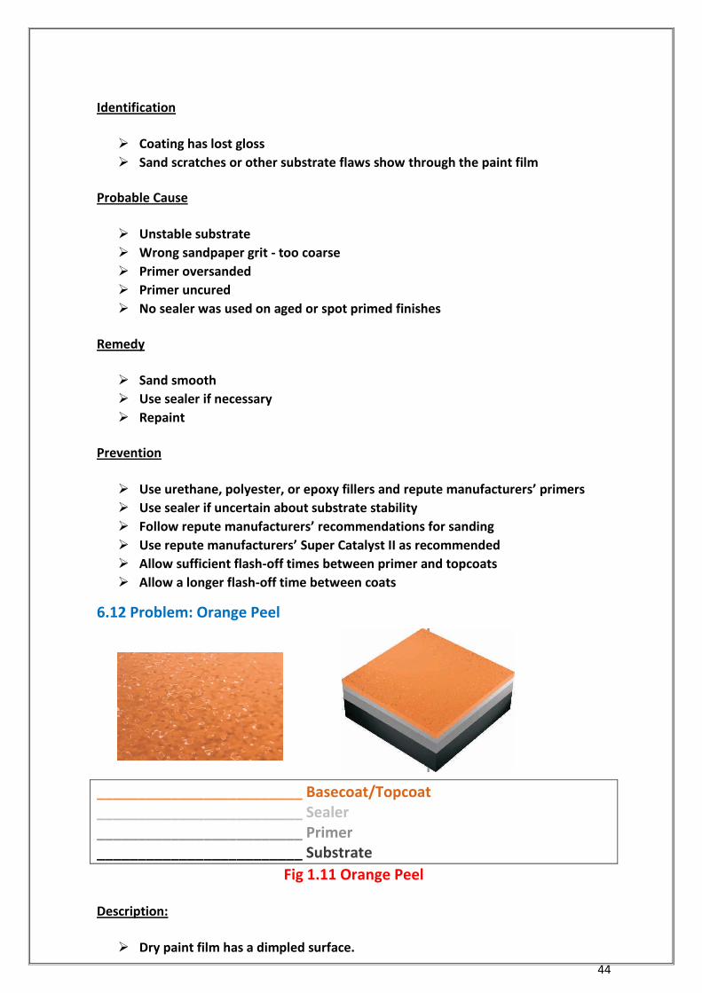
6.12 Problem: Orange Peel
_________________________ Basecoat/Topcoat _________________________ Sealer _________________________ Primer _________________________ Substrate
Fig 1.11 Orange Peel
Description:
Dry paint film has a dimpled surface.
45
Identification
Paint finish looks like the peel of an orange
Probable Cause
Viscosity too high
Gun air pressure too low (causing lack of atomization)
Primer or sealer applied not smooth
Wrong thinner/reducer
Incorrect spray technique:
- Holding gun too far from surface
- Wide fan patterns
Wrong amount of thinner or reducer used - not enough
Poor quality sanding
Remedy
Sand smooth
Repaint topcoat
Prevention
Proper surface preparation: carefully sand smooth
Check viscosity of products
Adjust gun set up:
- Use smaller size fluid tip
- Use air cap that increases paint atomization
Use recommended solvent
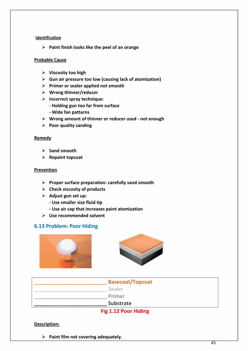
6.13 Problem: Poor Hiding
_________________________ Basecoat/Topcoat _________________________ Sealer _________________________ Primer _________________________ Substrate
Fig 1.12 Poor Hiding
Description:
Paint film not covering adequately.
46
Identification
Insufficient total film thickness
Finish has a transparent appearance
Dull finish, not glossy
Probable Cause
Insufficient film build
Not using basecoat when required for transparent colours
Wrong amount of thinner/reducer - too much
Insufficient lighting in the spray booth
Remedy
Sand smooth
Repaint
Prevention
Use recommended Hi-Hide formulation
Use the recommended base colour
Use a tinted primer when recommended
Follow repute manufacturers’ recommendations for reduction and number of
coats
Provide good lighting for spraying
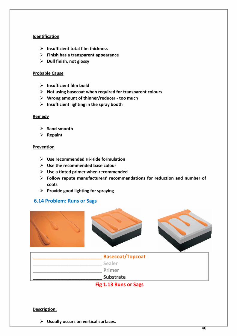
6.14 Problem: Runs or Sags
_________________________ Basecoat/Topcoat _________________________ Sealer _________________________ Primer _________________________ Substrate
Fig 1.13 Runs or Sags
Description:
Usually occurs on vertical surfaces.

47
A heavy paint film collects and moves downward, setting in ripples.
Identification
A rippled, distorted paint film
Probable Cause
Improper equipment set-up
Gun air pressure too low (causing lack of atomization)
Shop or substrate temperature too low
Temperature of paint product too low
Insufficient lighting in the spray booth
Incorrect solvent for conditions
Wrong amount of thinner/reducer used
-too much
Incorrect spray technique
-Holding gun too close to surface
-Application too heavy
Remedy
Sand smooth
Repaint
Prevention
Maintain a suitable, consistent shop temperature and airflow
Allow surface to warm up to at least room temperature before applying paint
Store paint products at room temperature
Provide good lighting for spraying Use proper gun settings and air pressure
- Use smaller size fluid tip
- Increase gun air pressure/increase atomization
- Decrease pot pressure
Use correct solvent for conditions
-fast solvents for cold conditions
Allow sufficient flash-off and drying time between coats
48
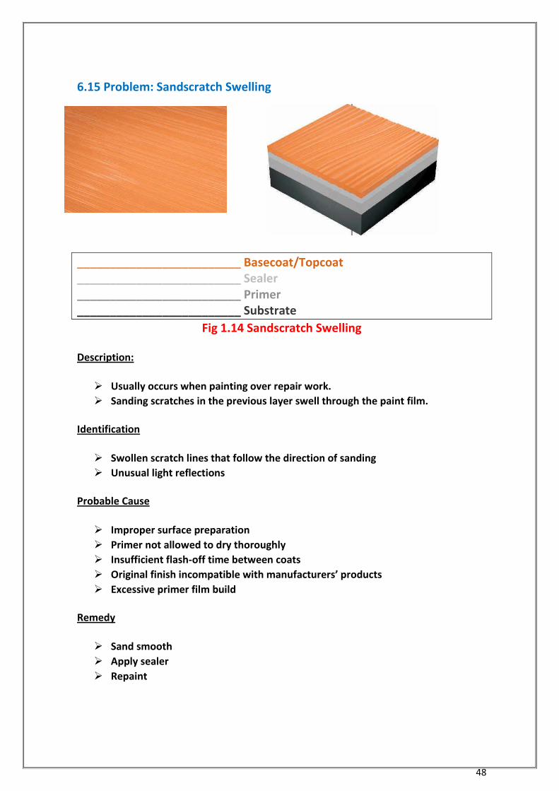
6.15 Problem: Sandscratch Swelling
_________________________ Basecoat/Topcoat _________________________ Sealer _________________________ Primer _________________________ Substrate
Fig 1.14 Sandscratch Swelling
Description:
Usually occurs when painting over repair work.
Sanding scratches in the previous layer swell through the paint film.
Identification
Swollen scratch lines that follow the direction of sanding
Unusual light reflections
Probable Cause
Improper surface preparation
Primer not allowed to dry thoroughly
Insufficient flash-off time between coats
Original finish incompatible with manufacturers’ products
Excessive primer film build
Remedy
Sand smooth
Apply sealer
Repaint
49
Prevention
Proper surface preparation: check recommended sandpaper grits
Finish any polyester type filler with a finer grit sandpaper
Completely seal porous substrates (sealer eliminates sandscratch swelling)
Follow recommended primer film thickness
Allow sufficient flash-off time between coats
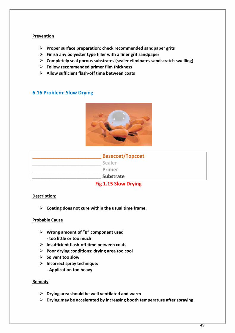
6.16 Problem: Slow Drying
_________________________ Basecoat/Topcoat _________________________ Sealer _________________________ Primer _________________________ Substrate
Fig 1.15 Slow Drying
Description:
Coating does not cure within the usual time frame.
Probable Cause
Wrong amount of “B” component used
- too little or too much
Insufficient flash-off time between coats
Poor drying conditions: drying area too cool
Solvent too slow
Incorrect spray technique:
- Application too heavy
Remedy
Drying area should be well ventilated and warm
Drying may be accelerated by increasing booth temperature after spraying
50
Prevention
Use correct amount of Component “B” Use recommended thinner
Use Suitable Catalyst as recommended by repute manufacturer
Use a faster solvent system Follow film thickness recommendations
Allow sufficient flash-off time Increase booth temperature after an adequate
flash-off period
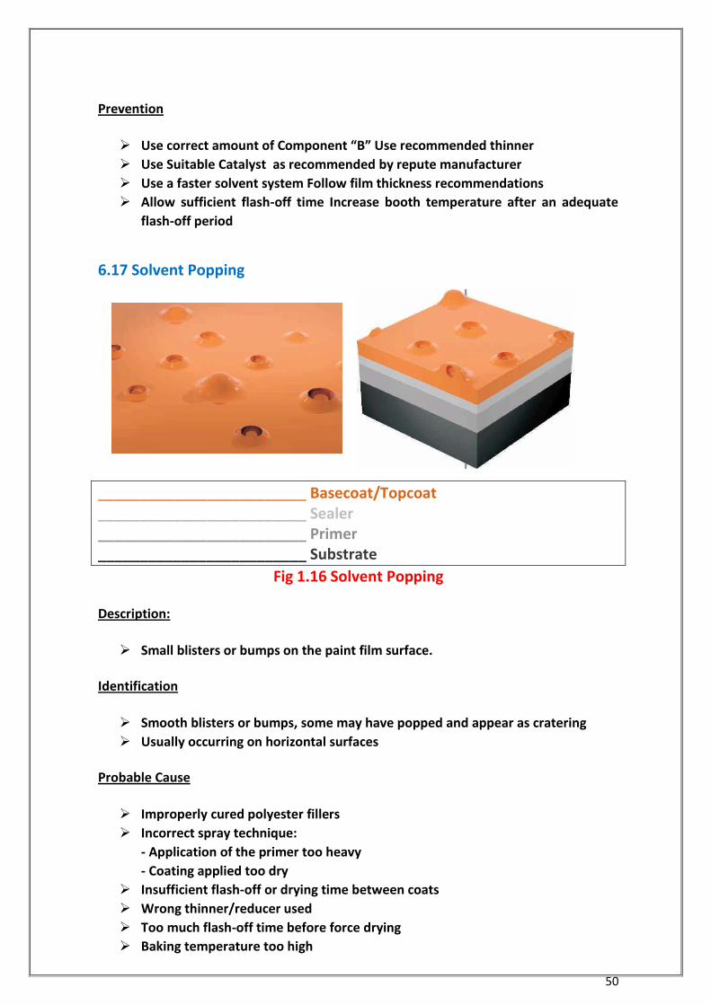
6.17 Solvent Popping
_________________________ Basecoat/Topcoat _________________________ Sealer _________________________ Primer _________________________ Substrate
Fig 1.16 Solvent Popping
Description:
Small blisters or bumps on the paint film surface.
Identification
Smooth blisters or bumps, some may have popped and appear as cratering
Usually occurring on horizontal surfaces
Probable Cause
Improperly cured polyester fillers
Incorrect spray technique:
- Application of the primer too heavy
- Coating applied too dry
Insufficient flash-off or drying time between coats
Wrong thinner/reducer used
Too much flash-off time before force drying
Baking temperature too high
51
Excessive use of Super Catalyst II
Remedy
Minor problem:
- Sand smooth
- Apply sealer
- Repaint
Major problem:
- Remove finish
- Repaint
Prevention
Ensure polyester type fillers are fully cured before priming
Completely seal porous substrates
Use correct solvent for conditions- slow solvent for hot conditions
Follow recommended film build thickness
Allow sufficient flash-off time between coats
Flash-off time of 5-10 minutes before forced drying
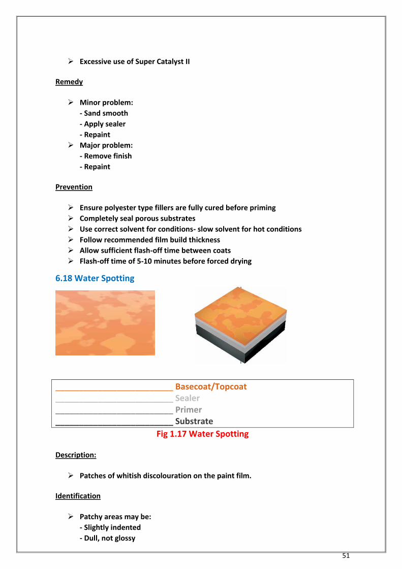
6.18 Water Spotting
_________________________ Basecoat/Topcoat _________________________ Sealer _________________________ Primer _________________________ Substrate
Fig 1.17 Water Spotting
Description:
Patches of whitish discolouration on the paint film.
Identification
Patchy areas may be:
- Slightly indented
- Dull, not glossy
52
- Cloudy, whitish
Probable Cause
Coating was exposed to moisture in the first 24 hours after painting
Coating was washed before the finish was cured
Remedy
Minor problem: polish
Major problem:
- Sand smooth
- Repaint
Prevention
Follow recommended cure times before washing or exposing to rain
Increase spray booth temperature
Use suitable Catalyst in topcoats as recommended
6.19 Wrinkling
Description
The film surface skins over and then swells, forming irregular ridges and creases.
Identification
Paint film forms creases, folds, and slight ridges
Film surface appears thick and leathery
Probable Cause
Solvent sensitive enamel under topcoat or primer
Primer or sealer not cured thoroughly
Incorrect spray technique:
- Application of topcoat too heavy
Wrong amount of “B” component used - too little
Remedy
Remove finish
Apply sealer
Repaint
Prevention
53
Check solvent sensitivity - perform a solvent rub test on existing finishes
Use sealers where appropriate
Allow sufficient flash-off times between coats
Use correct amount of Component “B”
54
Chapter 7 Pollution Prevention for the Coating Industry
7.1 Introduction
Pollution prevention, or P2, means preventing wastes rather than using expensive
treatment and control technologies on end-of-pipe wastes. P2 can decrease
environmental liabilities, reduce waste disposal costs, and improve working conditions.
It may be as simple as preventing spills and leaks through better housekeeping and
maintenance, or as complex as switching solvent-cleaning systems.
7.2 Development of Pollution Prevention Concepts
In 1990, beginning with the Pollution Prevention Act, EPA shifted focus from “end-of-
pipe” pollution treatment and cleanup to policies, technologies, and processes that
prevent and minimize the generation of pollution. The underlying theory behind P2 is
that it is economically more sensible to prevent wastes than implement expensive
treatment and control technologies to ensure waste does not threaten human health
and the environment.
7.3 P2 and the Coating Industry
Paint application wastes include leftover paints, dirty thinner from cleaning spray guns
and paint cups, air emissions of volatile organic compounds (VOCs) and hazardous air
pollutants (HAPs), dirty spray booth filters, dirty rags, and disposal of outdated supplies.
Ways to reduce these wastes include rigid inventory control, better housekeeping
practices, mixing paint according to need, better operator training, proper cleaning
methods, using alternative coatings, using Styrofoam filters, recycling solvents on and
off site, and using waste exchanges.
Better operating practices, or “good housekeeping” applies to all waste streams and
requires minimal capital investment, yet can be very effective in reducing the amount of
wastes generated. Good housekeeping includes management initiatives to increase
employee awareness of the need for and benefits of pollution prevention, and
preventive maintenance to reduce the number of leaks and spills.
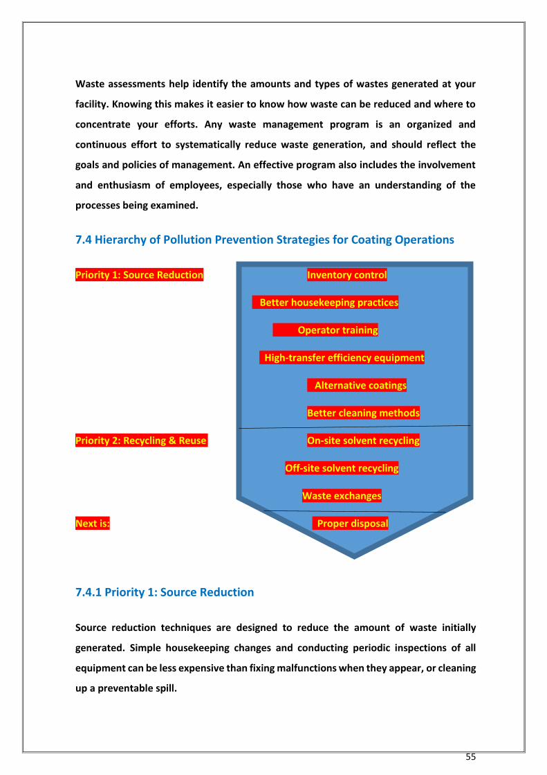
55
Waste assessments help identify the amounts and types of wastes generated at your
facility. Knowing this makes it easier to know how waste can be reduced and where to
concentrate your efforts. Any waste management program is an organized and
continuous effort to systematically reduce waste generation, and should reflect the
goals and policies of management. An effective program also includes the involvement
and enthusiasm of employees, especially those who have an understanding of the
processes being examined.
7.4 Hierarchy of Pollution Prevention Strategies for Coating Operations
Priority 1: Source Reduction Inventory control
Better housekeeping practices
Operator training
High-transfer efficiency equipment
Alternative coatings
Better cleaning methods
Priority 2: Recycling & Reuse On-site solvent recycling
Off-site solvent recycling
Waste exchanges
Next is: Proper disposal
7.4.1 Priority 1: Source Reduction
Source reduction techniques are designed to reduce the amount of waste initially
generated. Simple housekeeping changes and conducting periodic inspections of all
equipment can be less expensive than fixing malfunctions when they appear, or cleaning
up a preventable spill.
56
7.4.1.1 Inventory Control
Inventory control is an effective and efficient way of reducing indiscriminate use of raw
materials. By reducing the amount of paint that becomes unusable, you not only save
costs associated with waste disposal, but you also save costs associated with initial
product purchase. Mark receiving dates on your incoming paint products, and use a “first
in, first out” procedure to use older paint materials first.
Look at standardizing the paint types and colors you offer your customers. This can help
minimize the number of different paint products you keep in inventory, again lessening
the chance for paint product to go bad. Standardizing your paint types and colors also
provides you with another benefit—it minimizes the chance that a client’s particular
paint selection will provide you with a surprise and cause what may have previously
been a non-hazardous waste to become a new hazardous waste for you to handle. If
justified by volume demand, purchase your chief coating colors in 15-, 30-, or 55-gallon
reusable drums rather than 5-gallon pails. Just be sure that product won't sit around too
long.
If you have paint material that for one reason or another will not meet your clients’
specifications or expectations as a finished coat, use it as an undercoat or primer; or see
if you can find a business that can use the paint and sell it, even at reduced cost.
Monitor the amount of paint used by different workers to get the same jobs done. Shop
owners may monitor employee operations and make verbal or written comments on
product usage. Limit employee access to material storage areas, or develop some kind
of accounting system to track material use.
7.4.1.2 Better Housekeeping Practices
Basic housekeeping techniques can be very effective in reducing pollution. Many
methods are available to control and minimize material losses, which can be
implemented easily and at little or no cost to the operator. Specific approaches to bulk
material drum location, material transfer methods, evaporation, and drum transport can
effectively limit material loss.
57
Keep paint and solvent containers tightly closed to reduce evaporation,
emissions, and material dry-out.
Reduce leaks and spills by placing drums at points of highest use.
Use spigots or pumps when transferring materials from storage containers to
smaller containers.
Control evaporation by using tight-fitting lids and spigots.
Use drip pans.
Use secondary containment in bulk storage areas.
Move drums carefully to prevent damage or punctures, which could lead to leaks
or ruptures during future use.
7.4.1.3 Material Preparation
Look for ways to reduce the amount of solvent used in product pre-cleaning. Examine
substituting chemical cleaning for physical or mechanical cleaning when preparing the
product surface for painting application. Sand or particle blasting are some examples,
although they have their own environmental issues. Plastic media has been substituted
for sand in some blasting operations for both environmental and worker health issues.
The plastic media can be reused once separated from the stripped-paint waste, reducing
both purchasing and waste disposal costs. Dry ice is another alternative material for
blasting processes. If solvent cleaning is used, reduce solvent loss due to evaporation by
installing cleaning tank lids or increasing freeboard space in vapor degreasers.
7.4.1.4 Conversion Coatings
Avoid dirtying or soiling the substrate prior to the beginning of the cleaning process.
Analyze water for hardness and dissolved solids. Use alkaline cleaners or phosphate
compounds with hard water stabilizers where necessary. Use low-temperature,
energy-conserving alkaline cleaners or phosphate compounds.
7.4.1.5 Paint Mixing
For small jobs, the amount of paint prepared will often exceed the amount of paint
actually applied. Track usage rates for different paint types. Have various sizes of paint
58
mixing and sprayer cups available to limit over-mixing of paint for a specific project,
and to reduce the amount of solvent needed for equipment cleanup.
7.4.1.6 Better Operator Training and Employee Participation
Operators may be very skilled at producing high quality finishes, but poorly trained in
minimizing paint usage. Key points for operators include the following:
Do not arc the spray gun and blow paint into the air.
Maintain a fixed distance from the painted surface while triggering the gun.
Too much or too little overlap leads to wasted paint and heavy or lightly coated
areas. A 50% overlap pattern is typically recommended.
Air pressure should be kept low—this can increase transfer efficiency from 30 to
60 percent.
Keep the gun perpendicular to the surface being painted. Angling the gun leads
to some of the spray being too far from your product surface and a decrease in
transfer efficiency.
Ask your operators where they see improvements could be made—after all they work
with the equipment daily and may have suggestions not previously thought about.
Provide incentives to increase employee participation in whatever waste reduction or
recycling program you have. One business tracked the savings in material purchases
and money made from recycling activities and put this into a general employee
account to be used by the workers to improve their working stations and lunchroom.
7.4.1.7 Maintenance and Use of High-Transfer Efficiency Equipment
Less overspray means fewer air emissions. You can reduce the amount of waste you
generate by increasing the transfer efficiency of your coating process. Remember,
transfer efficiency is a measure of how much paint goes on the part, compared to how
much is sprayed. Typical transfer efficiency from conventional air guns ranges from 20
to 40 percent, thus 60 to 80 percent of the paint is overspray. Overspray is a function
of the design and operation of the system used and your operator application
techniques.
59
Talk to your equipment vendor about higher transfer efficiency equipment, and examine
the payback period by switching to such equipment. It may be that the amount of
material saved will justify upgrading your equipment.
Even if you've examined upgrading your equipment and have decided to continue with
your current process equipment, make sure it is in good working order—your painters'
performance depends on the condition of their tools. Poorly maintained equipment
may result in products that don’t meet customer demand and can reduce the transfer
efficiency of your operations.
7.4.1.8 Alternative Coatings
VOC emissions are related to the type of coating used and the number of coats necessary
for a high quality finish. Acrylic lacquers are typically thinned with solvent by 125 to 150
percent. With synthetic enamels, solvent thinning amounts to 15 to 33 percent.
Minimize or eliminate VOC emissions by substituting solvent based paint with
waterborne paint, high-solids paint, or with medium or low-solvent paint. Consider,
however, the desired final product specifications and the type of product being coated
when choosing substitute materials.
7.4.1.9 Proper Cleaning Methods
Wastes resulting from cleaning of the application equipment can be reduced by more
efficient cleaning methods. Reduce solvent use in equipment cleaning by scraping paint
cups or tanks into a separate container before rinsing the equipment with solvent. Make
use of Teflon-lined metal paint containers, which are easier to clean. Use an enclosed
gun-cleaning station. Spray solvent through the gun into the cleaning station where it is
captured for recovery and reuse. Schedule jobs so that large batches of items of similar
color are painted, instead of small batches of custom items, to reduce the amount of
dirty cleaning solvent and waste paint generated during change-out.

60
7.4.1.10 Filters
Suppliers or recyclers of thinners may replace and dispose of dirty spray booth filters for
a generator. It is the responsibility of the generator, however, to determine if these
filters are hazardous. Filters may be characteristic hazardous waste (toxicity) if they
contain enough metals or volatiles. The volatiles could come from the paint thinners
used or from the paint itself. The metals typically are found in paint pigments. When
cleaning paint equipment (including gun tips and hoses), solvent and/or thinners should
not be sprayed on filters (or into the air in the paint booth), as this could cause the filters
to become a listed waste (and this act is considered illegal disposal).
Because the filters are in a solid state rather than a liquid, they are not considered a
hazardous waste in Kansas due to ignitability (D001). It is important to remember,
however, that paint filters have been known to cause trash fires and that some local
trash haulers and transfer stations will not allow them to be disposed in the regular
trash.
Reusing and recycling can help to reduce waste disposal costs. Wastes may potentially
be used as raw materials for a process, or materials may be able to be recovered before
being disposed. Recovery technologies can either remove desired materials from a
waste stream before disposal or can directly use waste from one process as raw material
in another.
7.4.1.11 On-Site Solvent Recycling
Several alternatives are available for recycling solvent on site. Gravity separation is
inexpensive and relatively easy to implement by allowing the solvent/sludge mixture to
separate under inactive conditions. The clear solvent can then be decanted with a drum
pump and used for equipment cleaning, reducing the amount of wash solvent
purchased. Reclaimed solvent can be used for formulating primers and base coats, but
might create problems if not sufficiently pure.
61
For those facilities that generate larger quantities of waste solvent, on-site distillation
may provide a more cost-effective alternative. Batch distillation of all high-grade solvent
wastes can virtually eliminate the need for purchasing lower quality solvents for use in
preliminary painting operations and cleanup. An operator may reclaim four and one-half
gallons of thinner, with one-half gallon left as sludge from five gallons of paint and
thinner wastes. This ratio varies depending on the operations.
When determining the amount of hazardous waste your company generates each month
(done to determine which hazardous waste generator category you fall under),
remember to count any solvent that enters your distillation/solvent recycling unit, each
time it is placed in the unit. So while on-site solvent recycling may help you reduce your
waste disposal and solvent purchasing costs, it will not reduce your hazardous waste
generation rate.
7.4.1.12 Off-Site Solvent Recycling
Low-volume solvent users, or those who find it uneconomical to recycle contaminated
solvents on site, usually send their waste to commercial recyclers for recovery.
Commercial recyclers have versatile distillation processes and can handle large volumes
and varieties of solvents. Generally, solvent recyclers recover 70 to 80 percent of the
incoming spent solvents into reusable products. Recyclers often sell reclaimed solvents
back to the user.
In general, suppliers who offer recycling services include the cost of waste collection and
recycling in the price of their solvent. This increases the thinner cost, but effectively
eliminates separate hauling and disposal or recycling costs. It also reduces the
administrative burden on the owner.
62
Chapter 8 Proper Coating Techniques for Operators
8.1 Introduction
Techniques, which spray painters use during application have a definite effect on
transfer efficiency and offer waste reduction potential. Fundamentals of good spray
techniques consist of the following:
Proper overlap of the spray pattern
Proper gun speed
Proper distance of the gun from the part
Holding the gun perpendicular to the surface of the part
Triggering the gun at the beginning and end of each stroke
Proper overlap of spray patterns will be determined by the coating. Proper overlap may
range from 50 percent to 80 percent. Greater overlap may result in wasted strokes, and
less overlap may results in streaks
Since the flow of coating from the gun is consistent, the speed of the gun as it is moved
across the part should be consistent as well. Steady gun speed will help obtain a uniform
thickness of coating. A gun speed higher than manufacturer specifications can distort
the spray pattern and not permit the maximum amount of material to reach the surface.
The distance of the gun from the part must be consistent, since, again, the flow of
material from the gun is consistent. Generally, this will be six to eight inches for non-
electrostatic systems. Spray losses increase with the distance, as does solvent loss. This
solvent loss is often corrected by the addition of more solvent. This does not correct the
spray loss, and overspray still ends up in the spray booth.
Except for special conditions, the gun should be held perpendicular to the surface of the
part. Arcing the gun for hard-to-reach areas wastes material by applying an uneven coat.
This also may result in streaks. These areas should be compensated for by changing the
positioning of the gun or operator.
63
If the trigger of the gun is not released at the end of a stroke, the material continues to
flow and when the gun changes direction, momentary stopping of the gun results in an
accumulation of coating material. To avoid this piling, the operator may spray past the
edge of the surface, spraying material into the spray booth and wasting coating.
All manufacturer specifications should be checked to ensure that operators are using the
proper technique for their equipment. Operator training and experience will provide
operators with knowledge of various painting techniques needed to paint parts of
different configurations. Different techniques are helpful when painting inside corners,
outside corners, slender parts, round parts, flat parts, large parts, or small parts.
Standard operating techniques will not be fully successful if other problems exist, such
as room temperature changing throughout the day (which changes the viscosity of the
paint) or if equipment needs repair.
8.2 Conclusion
Operators cannot be expected to compensate for broken gauges, worn fluid tips, or
other equipment problems.
64
Chapter 9 Testing and Inspection of Paints
9.1 Introduction
It is nowadays a welcome change that most of the present day’s paint users attach much
importance to the choice of paint schemes and the quality of paints, which is revealed
by the paints they take in approaching a coating consultant for identifying the choice
of paint scheme and in testing the paint materials for maintaining quality. It is very
important and critical that the values of the various properties of the paint specified by
the buyer is maintained throughout the supplies made by the paint company and the
paint is properly applied by the applicator so that the user achieves the expected
performance of the coatings.
For this, testing of properties of the coating and inspection of the coating and inspection
/ monitoring during application of paint is very much necessary. Some of the important
properties like volume solids, viscosity, spreading rate and drying time can be
determined. The procedures for such tests are given below. No sophisticated
instrument is required for these tests. Many critical values can be monitored during the
application itself which are also described. Though these do not cover the total
specification of the paint, a meticulous monitoring of these properties would ensure a
major share of quality control that has a bearing on the performance of the coating later
in the machine at the end user’s place. This practice of monitoring during application
avoids future complications like obtaining higher than or lower thickness than specified
thickness that is noticeable after drying.
9.2 Testing Of Paints
Coating materials i.e. paints are formed of two components - volatile and non- volatile;-
the former containing organic solvents which evaporate into the atmosphere leaving
the non-volatile material which contain the film forming binder material along with
pigments and additives, forms the dry film. This liquid paint is a viscoelastic material
whose properties of viscosity, volume solids and wet film thickness are interrelated and
manipulation or tinkering of one impacts the other.
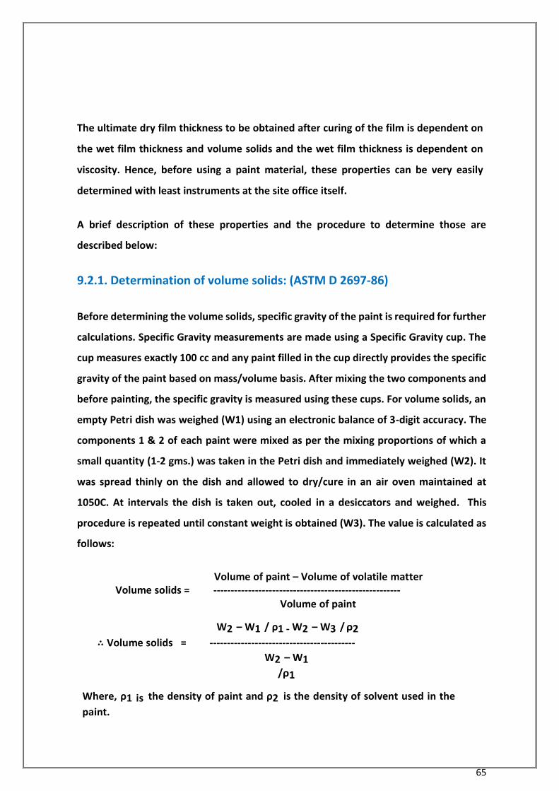
65
The ultimate dry film thickness to be obtained after curing of the film is dependent on
the wet film thickness and volume solids and the wet film thickness is dependent on
viscosity. Hence, before using a paint material, these properties can be very easily
determined with least instruments at the site office itself.
A brief description of these properties and the procedure to determine those are
described below:
9.2.1. Determination of volume solids: (ASTM D 2697-86)
Before determining the volume solids, specific gravity of the paint is required for further
calculations. Specific Gravity measurements are made using a Specific Gravity cup. The
cup measures exactly 100 cc and any paint filled in the cup directly provides the specific
gravity of the paint based on mass/volume basis. After mixing the two components and
before painting, the specific gravity is measured using these cups. For volume solids, an
empty Petri dish was weighed (W1) using an electronic balance of 3-digit accuracy. The
components 1 & 2 of each paint were mixed as per the mixing proportions of which a
small quantity (1-2 gms.) was taken in the Petri dish and immediately weighed (W2). It
was spread thinly on the dish and allowed to dry/cure in an air oven maintained at
1050C. At intervals the dish is taken out, cooled in a desiccators and weighed. This
procedure is repeated until constant weight is obtained (W3). The value is calculated as
follows:
Volume of paint – Volume of volatile matter Volume solids = ------------------------------------------------------
Volume of paint
W2 – W1 / ρ1 - W2 – W3 / ρ2
∴ Volume solids = ------------------------------------------
W2 – W1 /ρ1
Where, ρ1 is the density of paint and ρ2 is the density of solvent used in the
paint.

66
9.2.2. Viscosity
Viscosity, the resistance to flow, is an important property of paints to define by. Most
of the pigmented paint materials become ‘bodied’ materials and exhibit a property
called thixotropic property and they follow a flow pattern called thixotropic flow. These
viscoelastic properties have a bearing on the paint during its application. They
determine the wet film thickness (WFT) and consequently the dry film thickness (DFT)
of the applied film. As one of the main constituents of the paint, solvents are added to
adjust the viscosity of the liquid paint; the final viscosity of paint at the time of
application is to be determined. The WFT of a paint which depends on its viscosity has
a relationship with WFT based on the non-volatile matter content of the paint. Hence,
viscosity has a direct bearing on the DFT of the paint and by controlling the viscosity
during application; the DFT can be monitored during the application stage itself. This is
very important from a practical point of view as this monitoring can avoid later
complaints and controversies arising due to insufficient or higher than specified
thickness of paint films which are difficult to solve at that stage. Efflux type flow cup
viscometers are easy to use and more adaptable in the field during application of
paints. There are three types of widely used cups namely Ford cup, Zahn cup & Shell cup
with different orifice sizes.
Ford cup (of 100 ml capacity with 5 sizes of orifice)
Zahn cup (of 44 ml capacity with 5 sizes of orifice)
Shell cup (of 23 ml capacity with 6 sizes of orifice)
The cup is chosen depending on viscosity of the paint to be tested. For normal viscosity
paints Ford cup is used and for highly viscous paints, Shell and Zahn cups with large
opening sizes are used. The testing involves filling up of paint under testing followed
by opening of the orifice. The time taken for 100 cc of the paint to completely
drain from the cup is measured in seconds using a stop watch. In the case of Zahn cup,
the bottom is spherical and the volume is 44ml. The result obtained in seconds was
converted into poise units using standard tables.
67
9.2.3. Spreading Rate
Spreading rate, otherwise called Coverage, indicates the surface area that can be
covered by one liter or one kilogram of paint. In the laboratory, this is determined by
the volume/weight difference before and after applying the paint to a known area [eg.
0.25 sq.m] with paint. The paint company’s data sheet specifies a theoretical covering
area for each paint value of which is based on the area that the paint can cover if the
surface is smooth. But the surface to be painted is not always smooth and depending
upon the surface roughness, or the pits and other irregularities present in the surface
the actual area that can be covered is less than the theoretical value and also there is
lot of material losses during application of paint particularly while spraying, while the
loss is minimum when brushing, it is more during spraying. These are taken into account
while calculating the requirement or consumption of paint for a particular area. Hence
this valuing down is a cumulative effect of the condition of surface, method of
application and skill of the applicator.
9.2.4. Drying Time: (ASTM D 1005-95)
A paint film transforms from the state of a wet film to a dry film by the process of
evaporation of solvent and also by a chemical reaction among its constituents (in the
case of two component air drying systems). During the transformation, it undergoes
several changes in its structure. This process of drying has been classified in eight types
of drying times such as dry to touch, tack free, hard dry, print free etc.
By having the values of all the properties as described above, the WFT can be monitored
during application so that the final appropriate DFT is obtained using the following
relationship:
DFT = WFT x Volume solids value in fraction
By monitoring the WFT, all the future values can be monitored and many of the
future complications that are likely to arise can be avoided.
68
9.2.5. Inter-coat adhesion: (ASTM D 3359-93)
When two pack systems like epoxies and polyurethanes are applied, the adhesion
to a strict time interval between coats is necessary so that a proper inter-coat adhesion
between coatings is obtained. In multi-coat system, when a subsequent coat is applied
over an already applied coat, the solvent from the upper coat penetrates the bottom
coat and provides inter-coat adhesion between the two coats. This is very essential in
the case of multi-coat systems so that there is enough integration between coats
ensuring good performance of the total multi-coat system. This penetration of top coat
material can be more effective only when the bottom coat is not fully cured when the
overcoat is applied. If the bottom coat is allowed to fully cure, it is difficult for the over-
coat to penetrate a cured bottom coat leading to poor bonding between coats. This time
interval for the next coat is indicated in the specification of individual paint and has to
be followed meticulously in order to get the best performance from multi-coat systems.
9.3. Conclusion
All painting materials including primers, thinners, and paint components are to be
procured directly from the manufacturer or their authorized selling agents only. Each
item of the procurement MUST be accompanied by Quality certificate from the
Manufacturer in ORIGINAL and are to be offered to Inspection for verification. All
painting is to be carried out following the standard procedure laid out in the documents
and / or the manufacturers specified procedure. All paints procured for application
must be accompanied by documents detailing the application procedure.
Painting works shall be under constant monitoring from Inspection, and stage wise
inspection shall be offered FOR FOLLOWING SPECIFIC STAGES:
Surface preparation
Primer Application
Each coat of painting
Note: Any shop painting already applied should be recorded
69
Each inspection shall be documented and at the end of the job, submitted to inspection
Department.
Any defect, deviation detected during inspection shall be rectified to the full satisfaction
of Inspection.
General Inspection Guidelines:
Check for:
The Paint Manufacturer Certification
Manufacturing date and Expiry date
General health of the packing
Correctness of specification
Surface Cleanliness of the subject surface
Surrounding area to ensure non-contamination during or just after application
Surface cleaning equipment and procedure with due consideration to
safety
Proper surfaces after preparation free from all loose particles
Proper cleaning of nooks & corners and difficult to access location
Application Proper time lag from surface preparation to application Proper mixing (for two pack system)
Correct application tools, procedure and skill
Uniformity of wet film thickness per coat
Proper inter-coat time interval
Adequate post drying hardness

70
Annexure 1
List of Indian Standard for painting procedure for Machine Tools & other related standards
SL.
No. Reference Description
1 IS 10949-84 Painting Procedure for Machine Tools
2 IS 101 P1/Sec2 Methods of Sampling Paints – Preparation of samples for Testing
3 IS 101 P7/Sec1 Environmental Test on Paint Films – Resistance to Water
4 IS 101 P7/Sec4 Environmental Test on Paint Films – Resistance to Bleeding of Pigments
5 ASTM D 1654 - 92 Standard Test Method for Evaluation of Painted or Coated Specimens
Subjected to Corrosive Environments
6 ASTM D 3170 - 87 Standard Test method for Chipping Resistance Of coatings
7 ASTM D 5178 Standard Test Method for Mar Resistance of Organic Coatings
8 IS 101 P 6 / Sec : 1 Method of test for paints Resistance to humidity
9 IS 10949-84 Gray Surfacer
10 ASTM D 2247 - 94 Standard practice for Testing Water Resistance of Coatings in 100%
Relative humidity
11 ASTM D 4518 Standard Test Methods for Measuring for Static friction of coating
surfaces
12 IS 10949-84 Gray Putty Cellulose Base
13 IS 101 P7/Sec3 Environmental tests on Paint films – Resistance to Heat
14 IS 10949 –84 White Surface Primer
15 IS 101 P6/Sec3 Durability tests on Paint Films – Moisture, Vapour, Permeability.
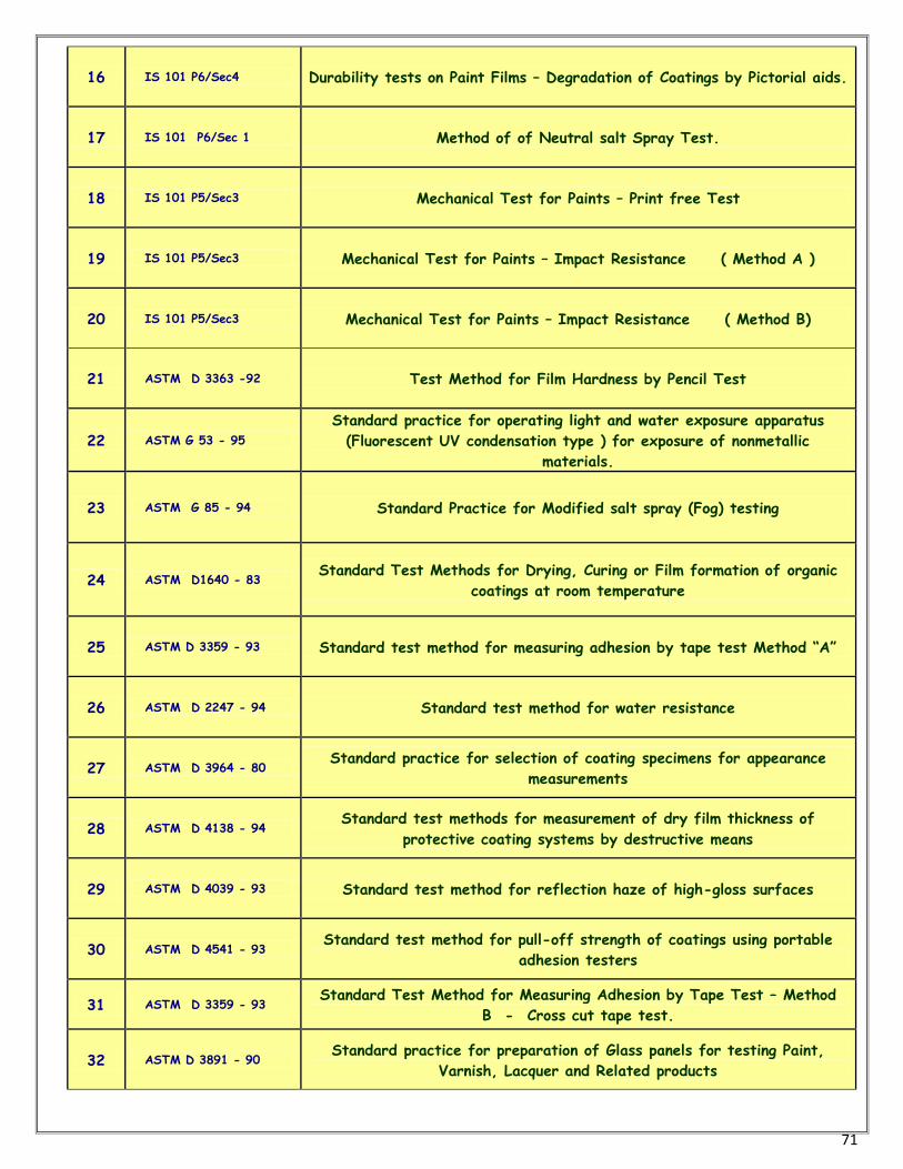
71
16 IS 101 P6/Sec4 Durability tests on Paint Films – Degradation of Coatings by Pictorial aids.
17 IS 101 P6/Sec 1 Method of of Neutral salt Spray Test.
18 IS 101 P5/Sec3 Mechanical Test for Paints – Print free Test
19 IS 101 P5/Sec3 Mechanical Test for Paints – Impact Resistance ( Method A )
20 IS 101 P5/Sec3 Mechanical Test for Paints – Impact Resistance ( Method B)
21 ASTM D 3363 -92 Test Method for Film Hardness by Pencil Test
22 ASTM G 53 - 95
Standard practice for operating light and water exposure apparatus
(Fluorescent UV condensation type ) for exposure of nonmetallic
materials.
23 ASTM G 85 - 94 Standard Practice for Modified salt spray (Fog) testing
24 ASTM D1640 - 83 Standard Test Methods for Drying, Curing or Film formation of organic
coatings at room temperature
25 ASTM D 3359 - 93 Standard test method for measuring adhesion by tape test Method “A”
26 ASTM D 2247 - 94 Standard test method for water resistance
27 ASTM D 3964 - 80 Standard practice for selection of coating specimens for appearance
measurements
28 ASTM D 4138 - 94 Standard test methods for measurement of dry film thickness of
protective coating systems by destructive means
29 ASTM D 4039 - 93 Standard test method for reflection haze of high-gloss surfaces
30 ASTM D 4541 - 93 Standard test method for pull-off strength of coatings using portable
adhesion testers
31 ASTM D 3359 - 93 Standard Test Method for Measuring Adhesion by Tape Test – Method
B - Cross cut tape test.
32 ASTM D 3891 - 90 Standard practice for preparation of Glass panels for testing Paint,
Varnish, Lacquer and Related products
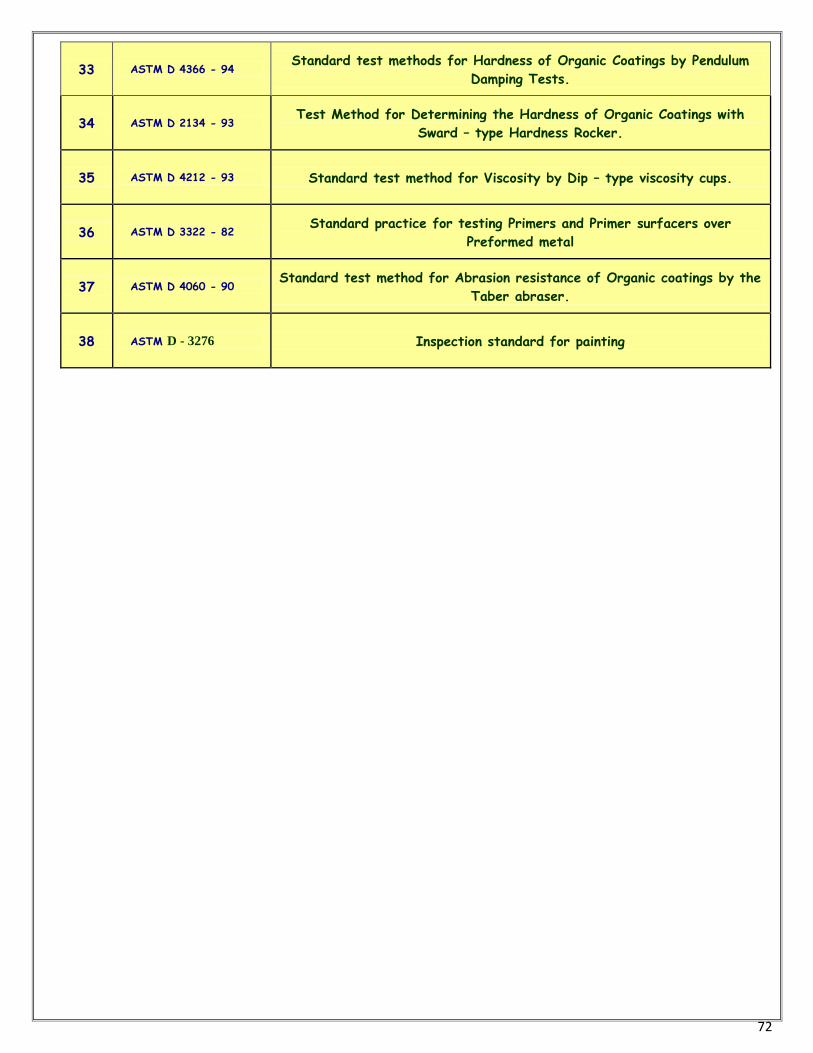
72
33 ASTM D 4366 - 94 Standard test methods for Hardness of Organic Coatings by Pendulum
Damping Tests.
34 ASTM D 2134 - 93 Test Method for Determining the Hardness of Organic Coatings with
Sward – type Hardness Rocker.
35 ASTM D 4212 - 93 Standard test method for Viscosity by Dip – type viscosity cups.
36 ASTM D 3322 - 82 Standard practice for testing Primers and Primer surfacers over
Preformed metal
37 ASTM D 4060 - 90 Standard test method for Abrasion resistance of Organic coatings by the
Taber abraser.
38 ASTM D - 3276 Inspection standard for painting
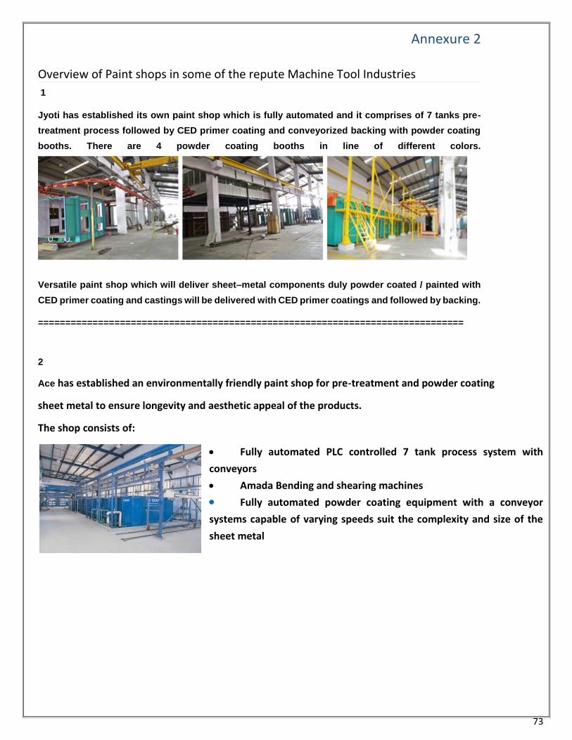
73
Annexure 2 Overview of Paint shops in some of the repute Machine Tool Industries 1
Jyoti has established its own paint shop which is fully automated and it comprises of 7 tanks pre-
treatment process followed by CED primer coating and conveyorized backing with powder coating
booths. There are 4 powder coating booths in line of different colors.
Versatile paint shop which will deliver sheet–metal components duly powder coated / painted with
CED primer coating and castings will be delivered with CED primer coatings and followed by backing.
==============================================================================
2
Ace has established an environmentally friendly paint shop for pre-treatment and powder coating
sheet metal to ensure longevity and aesthetic appeal of the products.
The shop consists of:
Fully automated PLC controlled 7 tank process system with
conveyors
Amada Bending and shearing machines
Fully automated powder coating equipment with a conveyor
systems capable of varying speeds suit the complexity and size of the
sheet metal
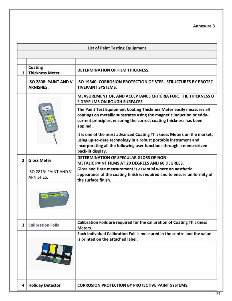
74
Annexure 3
List of Paint Testing Equipment
1 Coating Thickness Meter
DETERMINATION OF FILM THICKNESS.
ISO 2808: PAINT AND VARNISHES.
ISO 19840: CORROSION PROTECTION OF STEEL STRUCTURES BY PROTECTIVEPAINT SYSTEMS.
MEASUREMENT OF, AND ACCEPTANCE CRITERIA FOR, THE THICKNESS OF DRYFILMS ON ROUGH SURFACES
The Paint Test Equipment Coating Thickness Meter easily measures all coatings on metallic substrates using the magnetic induction or eddy-current principles, ensuring the correct coating thickness has been applied.
It is one of the most advanced Coating Thickness Meters on the market, using up-to-date technology in a robust portable instrument and incorporating all the following user functions through a menu-driven back-lit display.
2 Gloss Meter DETERMINATION OF SPECULAR GLOSS OF NON-METALIC PAINT FILMS AT 20 DEGREES AND 60 DEGREES.
ISO 2813: PAINT AND VARNISHES.
Gloss and Haze measurement is essential where an aesthetic appearance of the coating finish is required and to ensure uniformity of the surface finish.
3 Calibration Foils Calibration Foils are required for the calibration of Coating Thickness Meters.
Each individual Calibration Foil is measured in the centre and the value is printed on the attached label.
4 Holiday Detector CORROSION PROTECTION BY PROTECTIVE PAINT SYSTEMS.
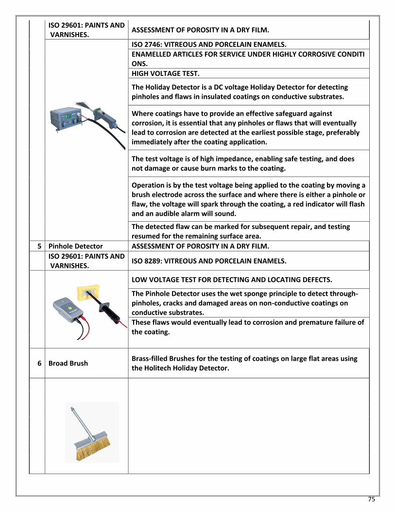
75
ISO 29601: PAINTS AND VARNISHES.
ASSESSMENT OF POROSITY IN A DRY FILM.
ISO 2746: VITREOUS AND PORCELAIN ENAMELS.
ENAMELLED ARTICLES FOR SERVICE UNDER HIGHLY CORROSIVE CONDITIONS.
HIGH VOLTAGE TEST.
The Holiday Detector is a DC voltage Holiday Detector for detecting pinholes and flaws in insulated coatings on conductive substrates.
Where coatings have to provide an effective safeguard against corrosion, it is essential that any pinholes or flaws that will eventually lead to corrosion are detected at the earliest possible stage, preferably immediately after the coating application.
The test voltage is of high impedance, enabling safe testing, and does not damage or cause burn marks to the coating.
Operation is by the test voltage being applied to the coating by moving a brush electrode across the surface and where there is either a pinhole or flaw, the voltage will spark through the coating, a red indicator will flash and an audible alarm will sound.
The detected flaw can be marked for subsequent repair, and testing resumed for the remaining surface area.
5 Pinhole Detector ASSESSMENT OF POROSITY IN A DRY FILM.
ISO 29601: PAINTS AND VARNISHES.
ISO 8289: VITREOUS AND PORCELAIN ENAMELS.
LOW VOLTAGE TEST FOR DETECTING AND LOCATING DEFECTS.
The Pinhole Detector uses the wet sponge principle to detect through-pinholes, cracks and damaged areas on non-conductive coatings on conductive substrates.
These flaws would eventually lead to corrosion and premature failure of the coating.
6 Broad Brush Brass-filled Brushes for the testing of coatings on large flat areas using the Holitech Holiday Detector.
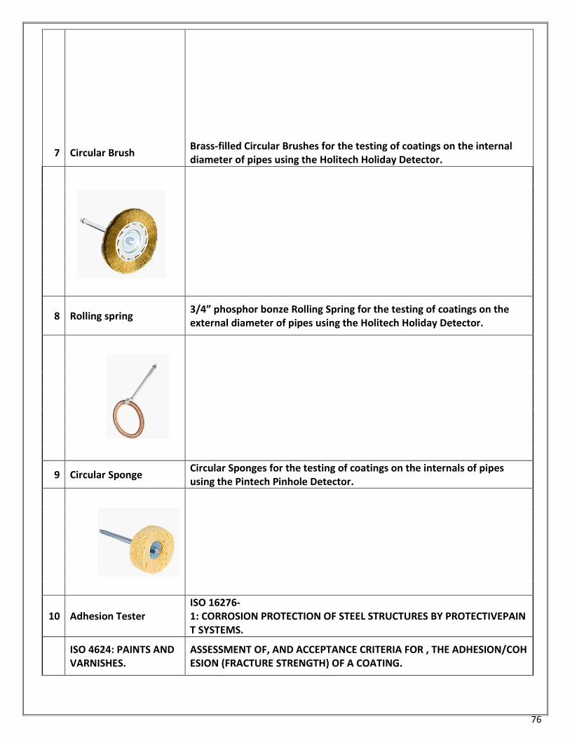
76
7
Circular Brush
Brass-filled Circular Brushes for the testing of coatings on the internal diameter of pipes using the Holitech Holiday Detector.
8 Rolling spring 3/4” phosphor bonze Rolling Spring for the testing of coatings on the external diameter of pipes using the Holitech Holiday Detector.
9 Circular Sponge Circular Sponges for the testing of coatings on the internals of pipes using the Pintech Pinhole Detector.
10 Adhesion Tester ISO 16276-1: CORROSION PROTECTION OF STEEL STRUCTURES BY PROTECTIVEPAINT SYSTEMS.
ISO 4624: PAINTS AND VARNISHES.
ASSESSMENT OF, AND ACCEPTANCE CRITERIA FOR , THE ADHESION/COHESION (FRACTURE STRENGTH) OF A COATING.
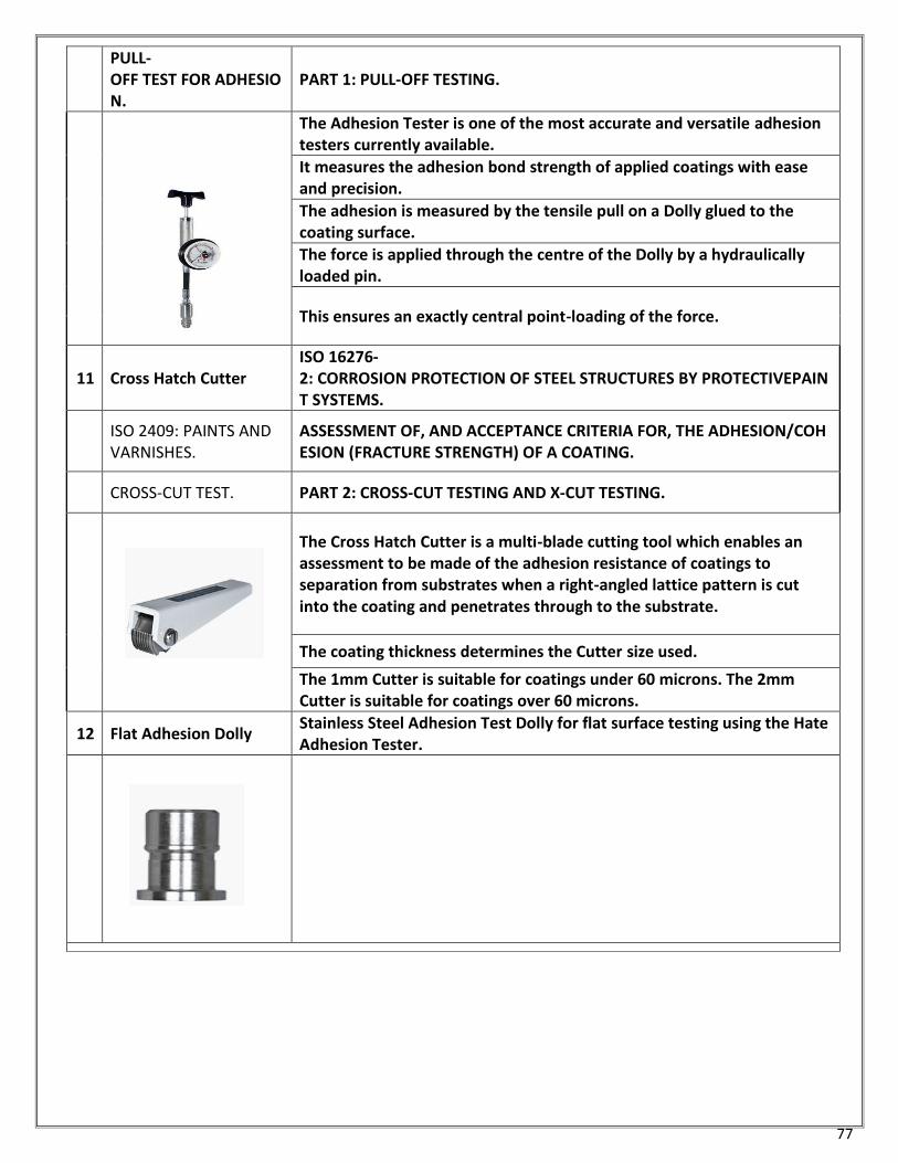
77
PULL-OFF TEST FOR ADHESION.
PART 1: PULL-OFF TESTING.
The Adhesion Tester is one of the most accurate and versatile adhesion testers currently available.
It measures the adhesion bond strength of applied coatings with ease and precision.
The adhesion is measured by the tensile pull on a Dolly glued to the coating surface.
The force is applied through the centre of the Dolly by a hydraulically loaded pin.
This ensures an exactly central point-loading of the force.
11 Cross Hatch Cutter ISO 16276-2: CORROSION PROTECTION OF STEEL STRUCTURES BY PROTECTIVEPAINT SYSTEMS.
ISO 2409: PAINTS AND VARNISHES.
ASSESSMENT OF, AND ACCEPTANCE CRITERIA FOR, THE ADHESION/COHESION (FRACTURE STRENGTH) OF A COATING.
CROSS-CUT TEST. PART 2: CROSS-CUT TESTING AND X-CUT TESTING.
The Cross Hatch Cutter is a multi-blade cutting tool which enables an assessment to be made of the adhesion resistance of coatings to separation from substrates when a right-angled lattice pattern is cut into the coating and penetrates through to the substrate.
The coating thickness determines the Cutter size used.
The 1mm Cutter is suitable for coatings under 60 microns. The 2mm Cutter is suitable for coatings over 60 microns.
12 Flat Adhesion Dolly Stainless Steel Adhesion Test Dolly for flat surface testing using the Hate Adhesion Tester.
78
Acknowledgement
IMTMA would especially wish to thank the following participants and their companies in the interactive
meeting for taking the time to share the information on various aspects of paint issues related to Machine
Tool Industry and for providing valuable inputs in the preparation of this Guide book:
Machine Tool Builders
Mr. Syed Amjed Mr. Basavaraj Kastur
Sr. Vice President-Global Marketing Kennametal India Ltd.
Bharat Fritz Werner Ltd. Bangalore
Mr. Chandrashekar Bharathi Mr. Suresh
Chairman and Managing Director General Manager - Business Development
AceMicromatic Manufacturing Intelligence Technology Pvt Ltd.
Makino India Pvt Ltd
Bangalore Bangalore
Mr. Jayasimha C K Mr. Saravana P R
National Sales Manager Shift Engineer
Miven Mayfran Conveyors Pvt. Ltd. Makino India Pvt Ltd
Hubli Bangalore
Mr. K. S. Prasanna Mr. Suresh Ramakrishna
Director Director
Pride Machine Tools Pvt. Ltd. Klad On Design Pvt. Ltd
Bangalore Bangalore
Mr. Narayan G Muramatti Mr. A Rakesh Kumar
CEO Assistant General Manager
Micromatic Grinding Technologies Ltd Yuken India Ltd.
Bangalore Bangalore
Mr. Shekhar H K Mr. Rajesh R N
Micromatic Grinding Technologies Ltd Manufacturing - Special Purpose Machines & Assembly Lines
Bangalore Bosch Limited
Bangalore
Mr. Paramesh A S
Micromatic Grinding Technologies Ltd Mr. Y Balaramaiah
Bangalore Director
Advanced Machine Tool Testing Facility Bangalore
79
Mr. Shashidhar Hiremath
Mr. T K Ramesh
Dy. General Manager CEO
Kennametal India Ltd. Micromatic Machine Tools Pvt. Ltd.
Bangalore Bangalore
Mr. Mohan Raj A Mr. A. Ramesh
JGM (MM) Manager- Paintshop
HMT Machine Tools Ltd. Ace Designers Ltd
Bangalore Bangalore
Mr. R Vimalesan Mr. Vishweswar
GM - Operation Purchase Executive
HMT Machine Tools Ltd. Ace Designers Ltd
Bangalore Bangalore
Mr. Rajendra S. Rajamane Mr. Prashanth Thankachan
Managing Director Chief Technology officer - R&D
Rajamane Industries Pvt. Ltd. UCAM Private Limited
Bangalore Bangalore
Mr. Ravishankar Shetty
Mr. Santosh Prabhu DGM
Managing Director Bharat Fritz Werner Ltd.
Tool Grinding Technologies Inc. Bangalore
Bangalore
Mr. Ramesh Joshi
Mr. Keshavamurthy Manager
Manager - Assembly Bharat Fritz Werner Ltd.
Ace Manufacturing Systems Ltd.
Bangalore
Mr. M P Anand
Sr Executive Procurement
Ace Manufacturing Systems Ltd.
Bangalore
80
Paint Manufacturers/Vendors
Mr. Pradeep Mr. Amirali Lalani
Varna Paints P.Ltd Shree Surya Coatings
Bangalore Nasik
Mr. B R Madhav Rao Mr. Nil Mani
Akzo Nobel India Limited Zigma Paints (P) Limited
Bangalore Nasik
Mr. Akshith Rakesh Reddy Mr. Nagesh.S.B
Akzo Nobel India Limited Marpol Pvt Ltd
Bangalore Bangalore
Mr. S. Manjunath Mr. Lakshman
Southfield Paints Limited Vijaya Vitala Chemicals Pvt.Ltd
Bangalore Bangalore
Mr. Bhagwan Dhumal
Swaraj Polycoats
Nasik
Note
The information and data used in this guide book has been sourced from a larger number of web-
sites,
Web-sites given for reference only. Addresses may change
User should refer latest information on all topics as these are modified continuously
All the information and data are given in good faith.
IMTMA is not responsible for accuracy and current validity; user to check with relevant sources for
latest information.
81
References/Sources
1. Painting manual – by Central Electrochemical Research Institute, Karaikudi, India
2. Industrial Painting & Coating – Prepared by the Kansas Small Business Environmental Assistance
Program
3. Surface Preparation – a note prepared by Vijaya Vital Chemicals Pvt. Ltd. Bangalore
4. Paint Removal – Report by CIMCOOL- Report No. J/N96/44
5. Paint Problems and Solutions Guide – by Endura manufacturing Co. Ltd. Edmonton, Alberts
6. Paint Guide – Surface preparation by Abolin Co.
7. www.hazard.uine.edu/wmr
8. http://americanmachinist.com/practical-ideas/covering-few-machine-painting-
tips
9. http://www.dei.ac.in/dei/distanceEducation/index.php/industrial-painting
10. http://www.cimcool.com/wp-content/uploads/tech-reports/newpaint.pdf
11. http://pdocs.masterchemical.com/mcc/docs/db-docs/tb_us-
english/Machine_Tool_Compatibility_Paint.pdf
12. https://law.resource.org/pub/in/bis/S01/is.10949.1984.pdf
13. http://www.madehow.com/Volume-1/Paint.html
14. http://www.rileysurfaceworld.co.uk/surface_treatments.asp