compilation and evaluation of results from - home | federal highway … · · 2007-03-27iii...
TRANSCRIPT

FOREWORD
In 1993, the Federal Highway Administration (FHWA) initiated a national program to implement the use of high-performance concrete (HPC) in bridges. The program included the construction of demonstration bridges throughout the United States. In addition, other States have implemented the use of HPC in various bridge elements. The construction of these bridges has provided a large amount of data on the use of HPC. The first part of this project involved collecting and compiling information from each joint State-FHWA HPC bridge project and other HPC bridge projects. The compilation is available on a CD-ROM and includes information on the benefits of HPC, costs, structural design, specified concrete properties, concrete mix proportions, measured properties, associated research projects, sources of data, and specifications. Information from 19 bridges in 14 States is included. A summary of the compiled information is provided in this final report. The second part of this project involved a review of the American Association of State Highway and Transportation Officials (AASHTO) Standard Specifications for Transportation Materials and Methods of Sampling and Testing, the AASHTO Standard Specifications for Highway Bridges, the AASHTO Load and Resistance Factor Design (LRFD) Bridge Design Specifications, and the AASHTO LRFD Bridge Construction Specifications for provisions that directly impact the use of HPC. The detailed review is included in this report. The third part of the project involved developing proposed revisions to the AASHTO specifications where sufficient research results exist to support the revisions. Proposed revisions to 15 material specifications, 14 test methods, 30 articles of the standard design specifications, 17 articles of the LRFD design specifications, and 16 articles of the LRFD construction specifications are included in this report. These proposed revisions were submitted to the appropriate AASHTO technical committees for consideration for adoption into the relevant specifications. Also in the third part of this project, a new material specification for combined aggregates and a new test method for slump flow are proposed. In addition, proposed revisions to the FHWA definition of HPC are included. The fourth part of the project involved developing specific recommendations for needed research where sufficient results do not exist to support needed changes in the specifications. Six research problem statements related to concrete materials and four research problem statements related to structural design are recommended. These research problem statements have been submitted to the appropriate Transportation Research Board technical committees for prioritization and funding recommendations.
Gary L. Henderson Director, Office of Infrastructure Research and Development
NOTICE
This document is disseminated under the sponsorship of the U.S. Department of Transportation in the interest of information exchange. The U.S. Government assumes no liability for its contents or use thereof. This report does not constitute a standard, specification, or regulation. The U.S. Government does not endorse products or manufacturers. Trade and manufacturers’ names appear in this report only because they are considered essential to the object of the document.
QUALITY ASSURANCE STATEMENT
FHWA provides high-quality information to serve Government, industry, and the public in a manner that promotes public understanding. Standards and policies are used to ensure and maximize the quality, objectivity, utility, and integrity of its information. FHWA periodically reviews quality issues and adjusts its programs and processes to ensure continuous quality improvement.

Technical Report Documentation Page 1. Report No. FHWA-HRT-05-057
2. Government Accession No. 3. Recipient’s Catalog No.
5. Report Date October 2006
4. Title and Subtitle Compilation and Evaluation of Results From High-Performance Concrete Bridge Projects, Volume II: Final Report 6. Performing Organization Code
7. Author(s) H.G. Russell, R.A. Miller, H.C. Ozyildirim, and M.K. Tadros
8. Performing Organization Report No. 10. Work Unit No. (TRAIS)
9. Performing Organization’s Name and Address Henry G. Russell, Inc. 720 Coronet Road Glenview, IL 60025 11. Contract or Grant No.
DTFH61-00-C-00009 13. Type of Report and Period Covered Final Report November 1999-February 2003
12. Sponsoring Agency’s Name and Address Federal Highway Administration 6300 Georgetown Pike McLean, VA 22101-2296
14. Sponsoring Agency’s Code
15. Supplementary Notes Contracting Officer’s Technical Representative (COTR): Joseph L. Hartmann, HRDI-06 16. Abstract In 1993, the Federal Highway Administration (FHWA) initiated a national program to implement the use of high-performance concrete (HPC) in bridges. The program included the construction of demonstration bridges throughout the United States. In addition, other States have implemented the use of HPC in various bridge elements. The construction of these bridges has provided a large amount of data on the use of HPC. The first part of this project involved collecting and compiling information from each joint State-FHWA HPC bridge project and other HPC bridge projects. The compilation is available on a CD-ROM and includes information on the benefits of HPC, costs, structural design, specified concrete properties, concrete mix proportions, measured properties, associated research projects, sources of data, and specifications. Information from 19 bridges in 14 States is included. A summary of the compiled information is provided in this final report. The second part of this project involved a review of the American Association of State Highway and Transportation Officials (AASHTO) Standard Specifications for Transportation Materials and Methods of Sampling and Testing, the AASHTO Standard Specifications for Highway Bridges, the AASHTO Load and Resistance Factor Design (LRFD) Bridge Design Specifications, and the AASHTO LRFD Bridge Construction Specifications for provisions that directly impact the use of HPC. The detailed review is included in this report. The third part of the project involved the development of proposed revisions to the AASHTO specifications where sufficient research results exist to support the revisions. Proposed revisions to 15 material specifications, 14 test methods, 30 articles of the standard design specifications, 17 articles of the LRFD design specifications, and 16 articles of the LRFD construction specifications are included in this report. In addition, a new materials specification for combined aggregates and a new test method for slump flow are proposed. Proposed revisions to the FHWA definition of HPC are also included. The fourth part of the project involved the development of specific recommendations for needed research where sufficient results do not exist to support needed changes in the specifications. Six research problem statements related to concrete materials and four research problems related to structural design are recommended. The final report associated with these appendices isCompilation and Evaluation of Results from High-Performance Concrete Bridge Projects, Volume I: Final Report (FHWA-HRT-05-056). 17. Key Words Bridges, cast-in-place concrete, high-strength concrete, high-performance concrete, precast concrete, prestressed concrete.
18. Distribution Statement No restrictions. This document is available to the public through the National Technical Information Service, Springfield, VA 22161.
19. Security Classif. (of this report) Unclassified
20. Security Classif. (of this page) Unclassified
21. No. of Pages 303
22. Price n/a
Form DOT F 1700.7 (8-72) Reproduction of completed page authorized

ii
SI* (MODERN METRIC) CONVERSION FACTORS APPROXIMATE CONVERSIONS TO SI UNITS
Symbol When You Know Multiply By To Find Symbol LENGTH
in inches 25.4 millimeters mm ft feet 0.305 meters m yd yards 0.914 meters m mi miles 1.61 kilometers km
AREA in2 square inches 645.2 square millimeters mm2
ft2 square feet 0.093 square meters m2
yd2 square yard 0.836 square meters m2
ac acres 0.405 hectares hami2 square miles 2.59 square kilometers km2
VOLUME fl oz fluid ounces 29.57 milliliters mL gal gallons 3.785 liters L ft3 cubic feet 0.028 cubic meters m3
yd3 cubic yards 0.765 cubic meters m3
NOTE: volumes greater than 1000 L shall be shown in m3
MASS oz ounces 28.35 grams glb pounds 0.454 kilograms kgT short tons (2000 lb) 0.907 megagrams (or "metric ton") Mg (or "t")
TEMPERATURE (exact degrees) oF Fahrenheit 5 (F-32)/9 Celsius oC
or (F-32)/1.8 ILLUMINATION
fc foot-candles 10.76 lux lxfl foot-Lamberts 3.426 candela/m2 cd/m2
FORCE and PRESSURE or STRESS lbf poundforce 4.45 newtons N lbf/in2 poundforce per square inch 6.89 kilopascals kPa
APPROXIMATE CONVERSIONS FROM SI UNITS Symbol When You Know Multiply By To Find Symbol
LENGTHmm millimeters 0.039 inches in m meters 3.28 feet ft m meters 1.09 yards yd km kilometers 0.621 miles mi
AREA mm2 square millimeters 0.0016 square inches in2
m2 square meters 10.764 square feet ft2
m2 square meters 1.195 square yards yd2
ha hectares 2.47 acres ackm2 square kilometers 0.386 square miles mi2
VOLUME mL milliliters 0.034 fluid ounces fl oz L liters 0.264 gallons gal m3 cubic meters 35.314 cubic feet ft3
m3 cubic meters 1.307 cubic yards yd3
MASS g grams 0.035 ounces ozkg kilograms 2.202 pounds lbMg (or "t") megagrams (or "metric ton") 1.103 short tons (2000 lb) T
TEMPERATURE (exact degrees) oC Celsius 1.8C+32 Fahrenheit oF
ILLUMINATION lx lux 0.0929 foot-candles fc cd/m2 candela/m2 0.2919 foot-Lamberts fl
FORCE and PRESSURE or STRESS N newtons 0.225 poundforce lbf kPa kilopascals 0.145 poundforce per square inch lbf/in2
*SI is the symbol for th International System of Units. Appropriate rounding should be made to comply with Section 4 of ASTM E380. e(Revised March 2003)

iii
COMPILATION AND EVALUATION OF RESULTS FROM HIGH-PERFORMANCE CONCRETE BRIDGES PROJECTS, VOLUME II: APPENDIXES
TABLE OF CONTENTS
SECTION PAGE
APPENDIX A—PROPOSED REVISIONS TO THE AASHTO STANDARD SPECIFICATIONS FOR TRANSPORTATION MATERIALS AND METHODS OF SAMPLING AND TESTING, PART I SPECIFICATIONS ........A–1 M 6 STANDARD SPECIFICATION FOR FINE AGGREGATE FOR
PORTLAND CEMENT CONCRETE................................................................A–3 M 80 STANDARD SPECIFICATION FOR COARSE AGGREGATE FOR
PORTLAND CEMENT CONCRETE................................................................A–5 M 6 AND M 80 STANDARD SPECIFICATIONS FOR FINE AGGREGATE
FOR PORTLAND CEMENT CONCRETE AND COARSE AGGREGATE FOR PORTLAND CEMENT CONCRETE.......................................................A–7
M 85 STANDARD SPECIFICATION FOR PORTLAND CEMENT ........................A–11 M 154 STANDARD SPECIFICATION FOR AIR-ENTRAINING ADMIXTURES
FOR CONCRETE.............................................................................................A–13 M 157 STANDARD SPECIFICATION FOR READY-MIXED CONCRETE ..........A–15 M 182 STANDARD SPECIFICATION FOR BURLAP CLOTH MADE FROM
JUTE OR KENAF ............................................................................................A–19 M 194 STANDARD SPECIFICATION FOR CHEMICAL ADMIXTURES
FOR CONCRETE.............................................................................................A–21 M 195 STANDARD SPECIFICATION FOR LIGHTWEIGHT AGGREGATES
FOR STRUCTURAL CONCRETE .................................................................A–23 M 205 STANDARD SPECIFICATION FOR MOLDS FOR FORMING
CONCRETE TEST CYLINDERS VERTICALLY .........................................A–25 M 240 STANDARD SPECIFICATION FOR BLENDED HYDRAULIC
CEMENT ..........................................................................................................A–27 M 241 STANDARD SPECIFICATION FOR CONCRETE MADE BY
VOLUMETRIC BATCHING AND CONTINUOUS MIXING ......................A–29 M 295 STANDARD SPECIFICATION FOR COAL FLY ASH AND RAW OR
CALCINED NATURAL POZZOLAN FOR USE AS A MINERAL ADMIXTURE IN CONCRETE .......................................................................A–33
M 302 STANDARD SPECIFICATION FOR GROUND GRANULATED BLAST-FURNACE SLAG FOR USE IN CONCRETE AND MORTARS .......................................................................................................A–35
M 307 STANDARD SPECIFICATION FOR MICROSILICA FOR USE IN CONCRETE AND MORTAR..........................................................................A–37
M XX1 STANDARD SPECIFICATIONS FOR COMBINED AGGREGATES FOR HYDRAULIC CEMENT CONCRETE...................................................A–41
iv
APPENDIX B—PROPOSED REVISIONS TO THE AASHTO STANDARD SPECIFICATIONS FOR TRANSPORTATION MATERIALS AND METHODS OF SAMPLING AND TESTING, PART II TESTS ............................B–1 T 22 STANDARD METHOD OF TEST FOR COMPRESSIVE STRENGTH
OF CYLINDRICAL CONCRETE SPECIMENS ..............................................B–3 T 23 STANDARD METHOD OF TEST FOR MAKING AND CURING
CONCRETE TEST SPECIMENS IN THE FIELD............................................B–7 T 24 STANDARD METHOD OF TEST FOR OBTAINING AND TESTING
DRILLED CORES AND SAWED BEAMS OF CONCRETE..........................B–9 T 106 STANDARD METHOD OF TEST FOR COMPRESSIVE STRENGTH
OF HYDRAULIC CEMENT MORTAR (USING 50-MM OR 2-IN. CUBE SPECIMENS)........................................................................................B–11
T 126 STANDARD METHOD OF TEST FOR MAKING AND CURING CONCRETE TEST SPECIMENS IN THE LABORATORY..........................B–13
T 132 STANDARD METHOD OF TEST FOR TENSILE STRENGTH OF HYDRAULIC CEMENT MORTARS .............................................................B–15
T 157 STANDARD METHOD OF TEST FOR AIR-ENTRAINING ADMIXTURES FOR CONCRETE .................................................................B–17
T 158 STANDARD METHOD OF TEST FOR BLEEDING OF CONCRETE..........B–19 T 161 STANDARD METHOD OF TEST FOR RESISTANCE OF CONCRETE
TO RAPID FREEZING AND THAWING ......................................................B–21 T 188 STANDARD METHOD OF TEST FOR EVALUATION BY FREEZING
AND THAWING OF AIR-ENTRAINING ADDITIONS TO PORTLAND CEMENT....................................................................................B–23
T 231 STANDARD METHOD OF TEST FOR CAPPING CYLINDRICAL CONCRETE SPECIMENS ..............................................................................B–25
T 259 STANDARD METHOD OF TEST FOR RESISTANCE OF CONCRETE TO CHLORIDE ION PENETRATION ...........................................................B–29
T 277 STANDARD METHOD OF TEST FOR ELECTRICAL INDICATION OF CONCRETE'S ABILITY TO RESIST CHLORIDE ION PENETRATION...............................................................................................B–31
T 285 STANDARD METHOD OF TEST FOR BEND TEST FOR BARS FOR CONCRETE REINFORCEMENT...................................................................B–33
T XX1 STANDARD METHOD OF TEST FOR SLUMP FLOW OF HYDRAULIC CEMENT CONCRETE. ..........................................................B–35
APPENDIX C—PROPOSED REVISIONS TO THE AASHTO STANDARD
SPECIFICATIONS FOR HIGHWAY BRIDGES ....................................................C–1 DIVISION I—DESIGN 3.3.6 DEAD LOAD ........................................................................................................C–3 8.3.3 REINFORCEMENT..............................................................................................C–5 8.5 EXPANSION AND CONTRACTION ....................................................................C–7 8.7 MODULUS OF ELASTICITY AND POISSON'S RATIO.....................................C–9 8.15.2.1.1 FLEXURE....................................................................................................C–11 8.19.1 MINIMUM SHEAR REINFORCEMENT........................................................C–15 9.1.2 NOTATIONS.......................................................................................................C–17

v
9.2 CONCRETE ...........................................................................................................C–19 9.15 ALLOWABLE STRESS .....................................................................................C–21 9.15.2.3 CRACKING STRESS ....................................................................................C–23 9.16 LOSS OF PRESTRESS. .......................................................................................C–27 9.20.3.3 SHEAR STRENGTH PROVIDED BY WEB REINFORCEMENT .............C–29 9.20.3.4 SHEAR STRENGTH PROVIDED BY WEB REINFORCEMENT .............C–31 9.23 CONCRETE STRENGTH AT STRESS TRANSFER ........................................C–33 DIVISION II—CONSTRUCTION 8.2.2 CLASSES OF CONCRETE ................................................................................C–35 8.3.1 CEMENTS...........................................................................................................C–37 8.3.5 COMBINED AGGREGATES.............................................................................C–39 8.3.7 MINERAL ADMIXTURES ................................................................................C–41 8.4.1 RESPONSIBILITY AND CRITERIA ................................................................C–43 8.4.3 CEMENT CONTENT .........................................................................................C–45 8.4.4 MINERAL ADMIXTURES ................................................................................C–47 8.5.7.1 TESTS...............................................................................................................C–49 8.5.7.3 FOR ACCEPTANCE OF CONCRETE ...........................................................C–51 8.5.7.5 STEAM AND RADIANT HEAT-CURED CONCRETE................................C–53 8.6.4.1 PROTECTION DURING CURE .....................................................................C–55 8.6.6 AND 8.6.7 CONCRETE EXPOSED TO SALT WATER AND CONCRETE
EXPOSED TO SULFATE SOILS OR WATER..............................................C–57 8.11.1 GENERAL.........................................................................................................C–59 8.11.3.5 STEAM OR RADIANT HEAT CURING METHOD ...................................C–61 8.11.4 BRIDGE DECKS...............................................................................................C–63 8.13.4 CURING ............................................................................................................C–65
APPENDIX D—PROPOSED REVISIONS TO THE AASHTO LRFD BRIDGE
DESIGN SPECIFICATIONS ......................................................................................D–1 3.5.1-1 DEAD LOADS...................................................................................................D–3 5.1 SCOPE ......................................................................................................................D–5 5.3 NOTATION..............................................................................................................D–7 C5.4.1 GENERAL ..........................................................................................................D–9 5.4.2.1 COMPRESSIVE STRENGTH .........................................................................D–11 C5.4.2.1-1 CONCRETE MIX CHARACTERISTICS BY CLASS .............................D–13 5.4.2.3 SHRINKAGE AND CREEP ............................................................................D–15 5.4.2.4 MODULUS OF ELASTICITY.........................................................................D–21 5.4.2.6 MODULUS OF RUPTURE .............................................................................D–23 5.4.6.2 SIZE OF DUCTS..............................................................................................D–27 5.5.4.1 STRENGTH LIMIT STATE—GENERAL AND 5.9.4.1.1 STRESS
LIMITS FOR CONCRETE—COMPRESSION STRESSES ..........................D–29 5.7.1 ASSUMPTIONS FOR SERVICE AND FATIGUE LIMIT STATES................D–31 5.8.2.8 DESIGN AND DETAILING REQUIREMENTS............................................D–33 5.9.5.1,2,3 LOSS OF PRESTRESS ..............................................................................D–37 5.9.5.4 REFINED ESTIMATES OF TIME-DEPENDENT LOSSES .........................D–49 5.12.2 ALKALI-SILICA REACTIVE AGGREGATES..............................................D–57 5.13.4.4.1 PILE DIMENSIONS ...................................................................................D–59

vi
APPENDIX E—PROPOSED REVISIONS TO THE AASHTO LRFD BRIDGE CONSTRUCTION SPECIFICATIONS.....................................................................E–1 8.2 CLASSES OF CONCRETE ..................................................................................... E–3 8.3.1 CEMENTS............................................................................................................. E–5 8.3.5 COMBINED AGGREGATES............................................................................... E–7 8.3.7 MINERAL ADMIXTURES .................................................................................. E–9 8.4.1 RESPONSIBILITY AND CRITERIA ................................................................ E–11 8.4.3 CEMENT CONTENT ......................................................................................... E–13 8.4.4 MINERAL ADMIXTURES ................................................................................ E–15 8.5.7.1 TESTS............................................................................................................... E–17 8.5.7.3 FOR ACCEPTANCE OF CONCRETE ........................................................... E–19 8.5.7.5 STEAM AND RADIANT HEAT-CURED CONCRETE................................ E–21 8.6.4.1 PROTECTION DURING CURE ..................................................................... E–23 8.6.6 AND 8.6.7 CONCRETE EXPOSED TO SALT WATER AND CONCRETE
EXPOSED TO SULFATE SOILS OR WATER.............................................. E–25 8.11.1 GENERAL......................................................................................................... E–27 8.11.3.5 STEAM OR RADIANT HEAT CURING METHOD ................................... E–29 8.11.4 BRIDGE DECKS............................................................................................... E–31 8.13.4 CURING ............................................................................................................ E–33
APPENDIX F—RESEARCH PROBLEM STATEMENTS................................................. F–1
F.1 MATERIALS RESEARCH PERFORMANCE REQUIREMENTS FOR HIGH-PERFORMANCE
CONCRETE ....................................................................................................... F–3 USE OF WASH WATER IN HIGH-PERFORMANCE CONCRETE.......................... F–7 AIR-VOID REQUIREMENTS AND FREEZE-THAW TESTING
REQUIREMENTS FOR DURABILITY OF HIGH-PERFORMANCE CONCRETE ..................................................................................................... F–11
PENETRABILITY CRITERIA FOR HIGH-PERFORMANCE CONCRETE ........... F–15 CURING OF HIGH-PERFORMANCE CONCRETE ................................................. F–19 PROCEDURES FOR MEASURING COMPRESSIVE AND FLEXURAL
STRENGTHS OF HIGH-STRENGTH CONCRETE...................................... F–23 F.2 STRUCTURAL RESEARCH APPLICATION OF BRIDGE DESIGN SPECIFICATIONS TO HIGH-
STRENGTH CONCRETE STRUCTURAL MEMBERS: MATERIAL PROPERTIES................................................................................................... F–27
APPLICATION OF BRIDGE DESIGN SPECIFICATIONS TO HIGH- STRENGTH CONCRETE STRUCTURAL MEMBERS: SHEAR PROVISIONS EXCEPT PRESTRESSED CONCRETE BEAMS .................. F–31
VERIFICATION OF STRESS LIMITS AND RESISTANCE FACTORS FOR HIGH-PERFORMANCE CONCRETE............................................................ F–35
CONFINEMENT OF HIGH-STRENGTH CONCRETE COLUMNS FOR SEISMIC AND NONSEISMIC REGIONS ..................................................... F–39
APPENDIX G—REFERENCES............................................................................................ G–1

A–1
APPENDIX A—PROPOSED REVISIONS TO THE AASHTO STANDARD SPECIFICATIONS FOR TRANSPORTATION MATERIALS AND METHODS OF
SAMPLING AND TESTING, PART I SPECIFICATIONS
TABLE OF CONTENTS
SECTION PAGE
M 6 Standard Specification for Fine Aggregate for Portland Cement Concrete ........................A–3
M 80 Standard Specification for Coarse Aggregate for Portland Cement Concrete ..................A–5
M 6 and M 80 Standard Specifications for Fine Aggregate for Portland Cement Concrete and Coarse Aggregate for Portland Cement Concrete.......................................................A–7
M 85 Standard Specification for Portland Cement ...................................................................A–11
M 154 Standard Specification for Air-Entraining Admixtures for Concrete ...........................A–13
M 157 Standard Specification for Ready-Mixed Concrete.......................................................A–15
M 182 Standard Specification for Burlap Cloth Made from Jute or Kenaf..............................A–19
M 194 Standard Specification for Chemical Admixtures for Concrete....................................A–21
M 195 Standard Specification for Lightweight Aggregates for Structural Concrete ...............A–23
M 205 Standard Specification for Molds for Forming Concrete Test Cylinders Vertically ....A–25
M 240 Standard Specification for Blended Hydraulic Cement ................................................A–27
M 241 Standard Specification for Concrete Made By Volumetric Batching and Continuous Mixing ..........................................................................................................A–29
M 295 Standard Specification for Coal Fly Ash and Raw or Calcined Natural Pozzolan for Use as a Mineral Admixture in Concrete ...................................................................A–33
M 302 Standard Specification for Ground Granulated Blast-Furnace Slag for Use in Concrete and Mortars.......................................................................................................A–35
M 307 Standard Specification for Microsilica for Use in Concrete and Mortar ......................A–37
M XX1 Standard Specifications for Combined Aggregates for Hydraulic Cement Concrete ...........................................................................................................................A–41


Appendix A
A–3
PROPOSED CHANGE TO AASHTO Standard Specifications for
Transportation Materials (X) Revision or ( ) Addition M 6 M 6 Standard Specification for Fine Aggregate for Portland Cement Concrete Revise title to read as follows: Standard Specification for Fine Aggregate for Portland Hydraulic Cement Concrete (Deleted text is indicated by strikethrough. Inserted text is underlined.) Other Affected Specifications or Sections Referenced Documents section in other AASHTO specifications or test methods will need to be changed. Background Most HPC contains pozzolans or slag; therefore, the word "hydraulic" is more appropriate. Anticipated Effect on Bridges Introduce correct terminology. References None (Submitted by: )


Appendix A
A–5
PROPOSED CHANGE TO AASHTO Standard Specifications for
Transportation Materials (X) Revision or ( ) Addition M 80 M 80 Standard Specification for Coarse Aggregate for Portland Cement Concrete Revise title to read as follows: Standard Specification for Coarse Aggregate for Portland Hydraulic Cement Concrete (Deleted text is indicated by strikethrough. Inserted text is underlined.) Other Affected Specifications or Sections Referenced Documents section in other AASHTO specifications or test methods will need to be changed. Background Most HPC contains pozzolans or slag; therefore, the word "hydraulic" is more appropriate. Anticipated Effect on Bridges Introduce correct terminology. References None (Submitted by: )


Appendix A
A–7
PROPOSED CHANGE TO AASHTO Standard Specifications for
Transportation Materials (X) Revision or (X) Addition M 6 and M 80 M 6 Standard Specification for Fine Aggregate for Portland Cement Concrete M 80 Standard Specification for Coarse Aggregate for Portland Cement Concrete Item No. 1 Add the following to Section 6.2 of M 80: Coarse aggregate for use in concrete that will be subject to wetting, extended exposure to humid atmosphere, or contact with moist ground shall not contain any materials that are deleteriously reactive with the alkalies in the cement in an amount sufficient to cause excessive expansion of mortar or concrete, except that if such materials are present in injurious amounts, the coarse aggregate may be used with a cement containing less than 0.6 percent alkalies calculated as sodium oxide equivalent or with the addition of a material that has been shown to prevent harmful expansion due to the alkali-aggregate reaction (Note X). (See Appendix A1 and Supplementary Requirement S1). Note X—In some areas with highly reactive aggregates, the 0.6 percent limit on alkalies may not be sufficient and a lower alkali content may be needed. Item No. 2 Replace the Supplementary Requirement S1 of M 6 and add a new Supplementary Requirement to M 80 as follows: S1 Reactive Aggregate S1.1 Potential reactivity of siliceous aggregates: Alkali-silica reactions shall be mitigated either by a performance specification as given in S1.1.1 or a prescriptive specification as given in S1.1.2: S1.1.1 Performance Type: One of the following options shall be used: 1. Obtain a service record of the aggregate with similar cementitious materials having similar
alkali content. If satisfactory, no mitigation is necessary. 2. Test the aggregate in accordance with AASHTO T 303 or ASTM C 1293. If the expansion is
less than 0.10 percent at 14 days after initial reading when tested in accordance with AASHTO T 303 or less than 0.04 percent at one year with ASTM C 1293, no mitigation is necessary.
3. If reactive aggregates are used, use pozzolan or slag, and test in accordance with ASTM C 441 to determine if the amount of pozzolan or slag is effective in mitigating deleterious reactions. For acceptance, the maximum expansion at 14 days shall not exceed 0.02 percent and at 56 days shall not exceed 0.10 percent.1 If specified, AASHTO T 303 test shall be used with the pozzolan or slag or blended cements to detect the potential for deleterious expansion. The test shall be performed by using 440 grams of the proposed blended cementitious materials, in the proportion to be used on the project, and 990 grams of the combined aggregates, in the proportions to be used on the project. For acceptance using AASHTO T 303, the expansion shall not exceed 0.10 percent at 14 days.
S1.1.2 Prescriptive Type: One of the following options shall be used: 1. Limit the alkali content of cement to a maximum of 0.6 percent or limit the alkali content in
portland cement concrete to 2.37 kg per cubic meter (4 lb per cubic yard).2,3

Appendix A
A–8
2. Select aggregates with proven field performance when similar cementitious materials having similar alkali content are used.
3. Use varying percentage of pozzolan or slag for different levels of alkali content of cement (Note Y).1
Note Y—Virginia Department of Transportation accepts the following combinations of cementitious materials for different alkali contents: Combination of Cementitious Materials* Max. Cement Alkali,
percent Cement only
Cement with minimum 15% Class F fly ash
Cement with minimum 20% Class F fly ash
Cement with minimum 25% Class F fly ash
Cement with minimum 30% Class F fly ash
Cement with minimum 25% slag
Cement with minimum 35% slag
Cement with minimum 50% slag
Cement with minimum 3% silica fume
Cement with minimum 7% silica fume
Cement with minimum 10% silica fume
0.45
0.60
0.68
0.75
0.83
0.60
0.90
1.00
0.60
0.90
1.00
* Percentages of Class F fly ash, slag, and silica fume are based on the total amount of cementitious materials. 4. Use lithium salts at a dosage rate of 1:1 LiOH.H2O : equivalent Na2O in the portland cement.3
____________________ 1 Lane, D. S. and Ozyildirim, C., "Preventive Measures for Alkali-Silica Reactions (Binary and Ternary Systems)," Cement and Concrete Research, Vol. 29, 1999, pp. 1281-1288. 2 Guide Specification for Concrete Subject to Alkali-Silica Reactions, IS415, Portland Cement Association, September 1998, 8 pp. 3 Stark, D., "Alkali-Silica Reactions in Concrete," Significance of Tests and Properties of Concrete and Concrete-Making Materials, ASTM STP 169C, 1994, pp. 365-371. Item No. 3 Add to Section 2. Referenced Documents in M 6 and M 80 as follows: 2.1 AASHTO Standards: T 303 Accelerated Detection of Potentially Deleterious Expansion of Mortar Bars Due to Alkali-Silica Reaction 2.2 ASTM Standards: C 441 Effectiveness of Mineral Admixtures or Ground Blast-Furnace Slag in Preventing Excessive

Appendix A
A–9
Expansion of Concrete Due to Alkali-Silica Reaction C 1293 Determination of Length Change of Concrete Due to Alkali-Silica Reaction (Deleted text is indicated by strikethrough. Inserted text is underlined.) Other Affected Specifications or Sections M 6 and M 80 Background Item Nos. 1 and 2 Supplementary requirement S1.1 of M 6 and Section 6.2 of M 80 indicate that cements with an upper limit of 0.6 percent alkalies can be used to inhibit alkali-silica reaction (ASR) when reactive aggregate is used. Generally, ASR can be controlled by using low alkali cement (less than 0.6 percent), a sufficient amount of an effective pozzolan, slag, blended cement, or lithium salts.(1,2,3) Tests can indicate the potentially deleterious aggregates and a lower alkali content than 0.6 percent may be needed in some areas. However, even if test results indicate potential expansions, an aggregate with a satisfactory service record with similar cementitious materials and conditions can be used. Item No. 3 Updating referenced documents. Anticipated Effect on Bridges More durable structures when reactive aggregates are used. References 1. Lane, D. S. and Ozyildirim, H. C., "Evaluation of the Effect of Portland Cement Alkali Content, Fly Ash, Ground Slag, and Silica Fume on Alkali-Silica Reactivity," Cement, Concrete, and Aggregates, Vol. 21, No. 2, December 1999, pp. 22-36. 2. ACI Committee 221, "State-of-the-Art Report on Alkali-Aggregate Reactivity (ACI 221.1R)," American Concrete Institute, Farmington Hills, MI, 1998. 3. Standard Practice to Identify Degree of Alkali-Reactivity of Aggregates and to Identify Measures to Avoid Deleterious Expansion in Concrete, A23.2-27A, Canadian Standards Association, Rexdale, ONT, September 2001. (Submitted by: )

Appendix A
A–11
PROPOSED CHANGE TO AASHTO Standard Specifications for
Transportation Materials (X) Revision or (X) Addition M 85 M 85 Standard Specification for Portland Cement Add the following to footnote d of Table 2—Optional Chemical Requirements: In some areas with highly reactive aggregates, the 0.6 percent limit on alkalies may not be sufficient and a lower alkali content may be needed. (Deleted text is indicated by strikethrough. Inserted text is underlined.) Other Affected Specifications or Sections None Background Alkali content may need to be lower in some areas to mitigate ASR.(1) M6 or M80 provide other options as well. Anticipated Effect on Bridges More durable structures when reactive aggregates are used. References 1. Stark, D., "Alkali-Silica Reactions in Concrete," Significance of Tests and Properties of Concrete and Concrete-Making Materials, ASTM STP 169C, 1994, pp. 365-371. (Submitted by: )


Appendix A
A–13
PROPOSED CHANGE TO AASHTO Standard Specifications for
Transportation Materials (X) Revision or (X) Addition M 154 M 154 Standard Specification for Air-Entraining Admixtures for Concrete Item No. 1 Revise Section 8. Test Methods as follows: 8.1 Determine the properties enumerated in Section 6 in accordance with Test Method C 233. It is recommended that, whenever practicable, tests be made in accordance with the section on Materials for Tests for Specific Uses in Test Method C 233, using the cement cementitious materials proposed for the specific work. Item No. 2 Add to Table—1 Physical Requirements as follows: Compressive strength, min, % of control: 1 day 90 3 days 90 7 days 90 28 days 90 56 daysB 90 Flexural strength, min, % of control: 3 days 90 7 days 90 28 days 90 56 daysB 90
B Applicable only when required by the purchaser (Deleted text is indicated by strikethrough. Inserted text is underlined.) Other Affected Specifications or Sections None Background Item No. 1 Most HPC contains pozzolans or slag. The effectiveness of air-entraining admixtures is affected by the use of pozzolans or slag. Consequently, all cementitious materials proposed for the specific work should be included. Item No. 2 56 days is a common test age and is used in the FHWA definition of HPC.(1) Anticipated Effect on Bridges Item No. 1 Makes the test more representative of the field conditions. Item No. 2 More economical concrete with improved properties and more realistic test age for HPC.

Appendix A
A–14
References 1. Goodspeed, C. H., Vanikar, S., and Cook, R., "High Performance Concrete Defined for Highway Structures," Concrete International, Vol. 18, No. 2, February 1996, pp. 62-67. (Submitted by: )

Appendix A
A–15
PROPOSED CHANGE TO AASHTO Standard Specifications for
Transportation Materials (X) Revision or (X) Addition M 157 M 157 Standard Specification for Ready-Mixed Concrete Item No. 1 Add to Section 2. Referenced Documents as follows: 2.1 AASHTO Standards: M 302, Ground Granulated Blast-Furnace Slag for Use in Concrete and Mortars M 307, Microsilica for Use in Concrete and Mortar M XX1, Combined Aggregates for Hydraulic Cement Concrete 2.2 ASTM Standards: C 1157 Hydraulic Cement Item No. 2 Revise Section 3.1 as follows: 3.1 For the purpose of this specification, ready-mixed concrete is portland hydraulic cement concrete manufactured for delivery to a purchaser in a plastic state and delivered as hereinafter specified. Item No. 3 Add ASTM C 1157 to Section 4.1.1 as follows: 4.1.1 Cement—Cement shall conform to Specification M 85 for Portland Cement or M 240 for Blended Hydraulic Cements, or ASTM C 1157 for Hydraulic Cement. Item No. 4 Replace Section 4.1.2 4.1.2 Fly ash used as an admixture or as a partial replacement for cement shall meet M 295 of the type specified or approved by the purchaser. with the following: 4.1.2 Other Cementitious Materials—Cementitious materials other than cement shall meet the requirements of the following specifications unless specified otherwise by the purchaser: Fly Ash—M 295 Ground Granulated Blast-Furnace Slag—M 302 Silica Fume—M 307 Item No. 5 Add the following at the end of Section 4.1.3 Aggregates: Combined aggregate grading, if used, shall conform to Specification M XX1. Item No. 6 Revise Section 5.1 as follows: The mix design may be specified by the engineer or submitted to the engineer by the Contractor for approval or a performance-based specification may be used. When specified by the engineer, it shall include the following: Item No. 7 Add new Section 5.3 as follows:

Appendix A
A–16
5.3 Performance-based Specification—Mix design shall be prepared and specified by those familiar with the material. The engineer shall specify the desired hardened concrete properties and permit the Contractor to design the mixture. Contractor will demonstrate through trial mixtures that the mix designs will provide the specified fresh and hardened properties. Selection of slump for placement shall be the responsibility of the Contractor. The Contractor shall make trial placements to demonstrate that concrete can be placed without any segregation, and without any difficulty in consolidating and finishing. Item No. 8 Revise Sections 5.1.1 and 5.1.3 as follows: 5.1.1 Cement Cementitious materials content in kg/m3 (lb/yd3) bags per cubic yard of concrete, or equivalent units. 5.1.3 Maximum allowable water content in gallons per bag of cement, or equivalent units, includingwater-cementitious materials ratio, where water includes surface moisture, but excludesing water of absorption, of the aggregates. Item No. 9 Revise Section 7.2 as follows: 7.2 The air-content of air-entrained concrete when sampled from the transportation unit at the point of discharge placement shall be within the purchaser specified tolerances. Where it is not practical to test at this point, comparison of values measured at the point of placement and the nearest practical location shall be established. Item No. 10 Add a note to Section 11.3.1 as follows: Note X—HPC mixtures especially those with stiff consistency having high cementitious materials content, low water-cementitious materials ratio, and several admixtures may need longer mixing times and higher number of revolutions for thorough mixing. Item No. 11 Revise Section 15.2 as follows: 15.2 If the measured slump, or air content, or unit weight falls outside the specified limits, a check test shall be made immediately on another portion of the same sample. In the event of a second failure, the concrete shall be considered to have failed the requirements of the specification. Unit weight shall be required for lightweight concretes, and is recommended for normal weight concretes. (Deleted text is indicated by strikethrough. Inserted text is underlined.) Other Affected Specifications or Sections None Background Item No. 1 Additional documents need to be added as described below. Item No. 2 Pozzolans and slag are widely used in HPC.(1) The specification needs to encompass all hydraulic cements.

Appendix A
A–17
Item No. 3 ASTM C 1157 is a standard performance specification for hydraulic cement. Performance specifications are desirable to promote innovation and encourage more economical construction. Item No. 4 Slag and silica fume are widely used in concrete and need to be included.(1)
Item No. 5 Combined aggregate grading is a proposed specification and should be included. Item Nos. 6 and 7 Performance-based specifications permit innovation and utilization of new products. Use of admixtures has a large effect on the slump of concrete. The Contractor should be responsible for the selection of slump. With the use of admixtures, slump can be easily adjusted to meet the needs of the project without affecting the water content. Item No. 8 Cement is replaced by cementitious materials since pozzolans and slag are widely used in HPC. Bags or sacks are not the proper measures. Item No. 9 Concrete in place is of interest. Delivery equipment such as a pump may alter the air-void system making the concrete less resistant to cycles of freezing and thawing. Item No. 10 HPC may contain different cementitious materials, high cementitious materials content, and more than one admixture. The mixture may be very cohesive. Longer mixing times may be appropriate to produce a uniform and consistent product. Item No. 11 Unit weight is a very useful test to check the air-content of the mixture. In lightweight concrete, unit weight is an important design criterion. Anticipated Effect on Bridges Improved concrete in bridge structures. References 1. High Performance Concrete, Compact Disc, Federal Highway Administration, Version 3.0, February 2003. (Submitted by: )


Appendix A
A–19
PROPOSED CHANGE TO AASHTO Standard Specifications for
Transportation Materials (X) Revision or (X) Addition M 182 M 182 Standard Specification for Burlap Cloth Made from Jute or Kenaf Item No. 1 Revise the title as follows: M 182 Standard Specification for Burlap Cloth Made from Jute or Kenaf, and Cotton Mats Item No. 2 Revise Section 1.1 as follows: 1.1 Scope—This specification covers requirements for burlap made from jute or kenaf, and cotton mats for use in curing concrete. Item No. 3 Add a new Section 1.4 as follows: 1.4 Cotton—Cotton is a vegetable fiber harvested from the cotton plant. The cotton plant belongs to the genus Gossypium of the family Malvaceae. Renumber existing Section 1.4 as 1.5. Item No. 4 Add a new Section 2.4 as follows: 2.4 Cotton mats shall consist of a filling material of cotton "bat" or "bats" of at least 400 g/m2 (12 oz. per sq. yd.); covered with unsized cloth at a minimum of 200 g/m2 (six (6) oz. per sq. yd); tufted or stitched to maintain stability. Item No. 5 Revise the first sentences in Sections 3.1 and 3.2 as follows: 3.1 The burlap and cotton mats shall be clean, evenly woven, and shall conform to the quality and grade of product requirements established by this specification. 3.2 The burlap and cotton mats shall be examined visually for defects which would impair its their suitability for use. Item No. 6 Revise Sections 4.1 and 4.2 as follows: 4.1 Lot—Unless otherwise specified, cloth and cotton mats of the same class presented at one time shall be considered a lot for purposes of inspection and tests. 4.2 Sampling for Test—Unless otherwise specified, random samples of cloth and cotton mats shall be taken from each inspection lot in accordance with the following table. Item No. 7 Revise Sections 6.1 and 6.2 as follows: 6.1 The burlap cloth and cotton mats shall be packed in a manner acceptable to common carriers for safe transportation to point of destination specified in shipping instructions at the lowest transportation rate for such supplies. 6.2 Each roll or cotton mat shall have a ticket attached to the selvage at the inner end of the cloth or cotton mat giving the length and width, and name and address of the manufacturer.

Appendix A
A–20
(Deleted text is indicated by strikethrough. Inserted text is underlined.) Other Affected Specifications or Sections None Background Cotton mats are used successfully in some states such as Texas and New Hampshire and are very effective for curing HPC bridge decks.(1) Anticipated Effect on Bridges Improved curing practices that will result in more durable concrete decks with less cracking. References 1. Texas DOT specifications for curing materials for concrete. (Submitted by: )

Appendix A
A–21
PROPOSED CHANGE TO AASHTO Standard Specifications for
Transportation Materials (X) Revision or (X) Addition M 194 M 194 Standard Specification for Chemical Admixtures for Concrete Item No. 1 Revise Section 1.1 as follows: This specification covers materials for use as chemical admixtures to be added to portland hydraulic cement concrete mixtures in the field for the purpose or purposes indicated for the seven types as follows: Item No. 2 In Table 1 Physical Requirements, for compressive strength and flexural strength, add a new line for 56 days with the same requirements as listed currently for 28 days. (Deleted text is indicated by strikethrough. Inserted text is underlined.) Other Affected Specifications or Sections None Background Item No. 1 It is very common to use other cementitious materials with portland cements.(1) Consequently, the term hydraulic cement concrete should be used. Item No. 2 Test age of 56 days is common for HPC and is used in the FHWA definition of HPC.(1)
Anticipated Effect on Bridges More economical concrete with improved properties. References 1. Goodspeed, C. H., Vanikar, S., and Cook R. A. "High Performance Concrete Defined for Highway Structures," Concrete International, Vol. 18, No. 2, February 1996, pp. 62-67. (Submitted by: )


Appendix A
A–23
PROPOSED CHANGE TO AASHTO Standard Specifications for
Transportation Materials (X) Revision or (X) Addition M 195 M 195 Standard Specification for Lightweight Aggregates for Structural Concrete Item No. 1 Add to Section 2. Referenced Documents as follows: 2.1 AASHTO Standards: M XX1 Combined Aggregates for Hydraulic Cement Concrete Item No. 2 Revise Section 5.1.2 to read as follows: 5.1.2 Grading—The grading shall conform to the requirements shown in Table 1 or the requirements of M XX1. (Deleted text is indicated by strikethrough. Inserted text is underlined.) Other Affected Specifications or Sections M XX1 Background Item No. 1 A new Standard Specification for Combined Aggregates for Hydraulic Cement Concrete has been proposed and is identified as M XX1. Item No. 2 The new specification needs to be referenced in M 195. Anticipated Effect on Bridges Improved workability and hardened concrete properties. References None (Submitted by: )


Appendix A
A–25
PROPOSED CHANGE TO AASHTO Standard Specifications for
Transportation Materials (X) Revision or (X) Addition M 205 M 205 Standard Specification for Molds for Forming Concrete Test Cylinders Vertically Item No. 1 Revise Section 5.1 as follows: 5.1 Single-use molds may be made of sheet metal, plastic, suitably treated paper products, or other materials and must conform to the requirements of this specification. Paper molds shall not be used. Item No. 2 Renumber existing Section 5.5.3 as 5.5.4 and add a new Section 5.5.3 as follows: 5.5.3 Top Cap—Sheet metal or plastic molds for use with concrete having a specified compressive strength greater than 6000 psi (40 MPa) shall be provided with tightly fitting domed metal or domed plastic caps to maintain the circular shape at the top of the cylinder and to provide a clearance above the finished concrete surface. (Deleted text is indicated by strikethrough. Inserted text is underlined.) Other Affected Specifications or Sections None Background Item No. 1 High-quality paper molds have been shown to result in measured concrete compressive strengths about 13 percent lower than when steel molds are used.(1) Item No. 2 Sheet metal and plastic molds with thin walls have a tendency to become out of round. Consequently, it is recommended that caps be required to retain the roundness. Dome caps ensure that the concrete surface is not deformed.(2) Anticipated Effect on Bridges Improved quality control. References 1. Blick, R. L., "Some Factors Influencing High-Strength Concrete," Modern Concrete, Vol. 36, No. 12, April 1973, pp. 38-41. 2. ACI Committee 363, "Guide to Quality Control and Testing of High-Strength Concrete, (ACI 363.2R-98)" American Concrete Institute, Farmington Hills, MI, 1998. (Submitted by: )


Appendix A
A–27
PROPOSED CHANGE TO AASHTO Standard Specifications for
Transportation Materials (X) Revision or (X) Addition M 240 M 240 Standard Specification for Blended Hydraulic Cement Item No. 1 Add to Table 2—Physical Requirements as follows: Compressive strength, min, MPa (psi) 28 or 56a days Heat of Hydration 28 or 56 a days a Only applicable when testing at 56 days is specified. Item No. 2 Revise Table 3—Requirements for Pozzolan for Use in Blended Cements and for Slag for Use in Slag-Modified Portland Cements as follows: Slag or pozzolan activity index: with portland cement, at 28 or 56a days, min. percent. a Only applicable when testing at 56 days is specified. (Deleted text is indicated by strikethrough. Inserted text is underlined.) Other Affected Specifications or Sections None Background Item Nos. 1 and 2 Test age of 56 days is common and used in the FHWA definition of HPC.(1) Anticipated Effect on Bridges Item Nos. 1 and 2 More economical construction. References 1. Goodspeed, C. H., Vanikar, S., and Cook, R., "High Performance Concrete Defined for Highway Structures," Concrete International, Vol. 18, No. 2, February 1996, pp. 62-67. (Submitted by: )


Appendix A
A-29
PROPOSED CHANGE TO AASHTO Standard Specifications for
Transportation Materials (X) Revision or (X) Addition M 241 M 241 Standard Specification for Concrete Made By Volumetric Batching and Continuous Mixing Item No. 1 In Section 2. Referenced Documents, correct the titles of 211.1 and 211.2 and add M 307, C 1157, and 211.4R as follows: 211.1 Recommended Standard Practice for Selecting Proportions for Normal, and Heavyweight, and Mass Concrete 211.2 Recommended Standard Practice for Selecting Proportions for Structural Lightweight Concrete M 307 Microsilica for Use in Concrete and Mortar C 1157 Blended Hydraulic Cement 211.4R Guide for Selecting Proportions for High-Strength Concrete with Portland Cement and Fly Ash Item No. 2 Revise first sentence of Section 5.1.1 as follows: 5.1.1 Cement—Cement shall conform to Specification C 150, or Specification C 595, or Specification C 1157 (Note 2). Item No. 3 Renumber Sections 5.1.6 and 5.1.7 as 5.1.7 and 5.1.8, respectively. Add new Section 5.1.6 as follows: 5.1.6 Silica Fume—Silica fume shall conform to Specification M 307. Item No. 4 Add to Section 6.1.3 the definition of point of discharge as follows: 6.1.3 When air-entrained concrete is specified, the air content of samples taken at the point of dischargeplacement from the transportation unit (see Section 10 and Table 3 for the total air content and tolerances) (Note 5)., Point of placement is at the final location of the concrete. Where it is not practical to test at this point, comparison of values measured at the point of placement and the nearest practical location shall be established. Item No. 5 Add the following to Section 6.1.5 about ordering: 6.1.5 Which of Options A, B, or C shall be used as a basis for determining the proportions of the concrete to produce the required quality (see 6.2, 6.3, or 6.4). Option B shall not be used with performance-based specifications. Item No. 6 Revise the second sentence of Note 7 as follows: Note 7—The purchaser, in selecting requirements for which he assumes responsibility should give consideration to requirements for workability, placeability, durability, surface texture, and density, in addition to those for structural design. The purchaser is referred to ACI RecommendedStandard Practice 211.1 for normal weight concrete, and ACI Recommended Standard Practice 211.2 for lightweight concrete, and ACI Guide 211.4R for high-strength concrete with fly ash, for the

Appendix A
A-30
selection of proportions that will result in concrete suitable for various types of structures and conditions of exposure. The water-cement ratio of most structural lightweight concretes cannot be determined with sufficient accuracy for use as a specification basis. Item No. 7 Revise the last sentence of Note 8 as follows: Attention is directed to ACI Publications Recommended Practices 211.1, and 211.2, and 211.4R for additional information on mixture proportions. Item No 8 Add to Note 15 and revise title and footnote C of Table 4 Overdesign Necessary to Meet Strength Requirements as follows: Note 15—Due to variations in materials, operations, and testing the average strength necessary to meet these requirements will be substantially higher than the specified strength. The amount higher depends upon the standard deviation of the test results and the accuracy with which that value can be estimated from prior data as explained in ACI 318 and ACI 301. Pertinent data is given in Table 4. for specified strengths up to 5000 psi (35 MPa) and Table 5 for specified strengths greater than 5000 psi (35 MPa). C If less than 15 prior tests are available, the overdesign should be 1000 psi (7.0 MPa) for specified strength less than 3000 psi (20 MPa), and 1200 psi (8.5 MPa) for specified strengths from 3000 to 5000 psi (20 to 35 MPa). and 1400 psi (10.0 MPa) for specified strengths greater than 5000 psi (35 MPa). Table 5 Required Average Strength to Meet Strength Requirements for '
cf > 5000 psi (35 MPa)
Number of TestsA
Required Average Compressive Strength
Less than 15 1.10 'cf + 700 in psi
(1.10 'cf + 5.0 in MPa)
15 or more Use the larger value computed by M( '
cf +1.34s)
M(0.90 'cf + 2.33s)
where
'cf = specified compressive strength
M = modification factor given in Table 6 A Number of tests of a concrete mixture used to estimate the standard deviation of a concrete production facility. The mixture used must have a strength within 1000 psi (7 MPa) of that specified and be made with similar materials. See ACI 318.

Appendix A
A-31
Table 6 Modification Factors Number of Tests M 15 20 25 30 or more
1.16 1.08 1.03 1.00
For intermediate number of tests, use linear interpolation. Revise title of Table 4 as follows: Table 4 Overdesign Necessary to Meet Strength Requirements for '
cf ≤ 5000 psi (35 MPa)A
Item No. 9 Revise Section 11.2 as follows:
11.2 One strength test set of at least two or at least three cylinders as described in Section 11.3 cylinders and the accompanying slump, temperature, and air content tests shall be made for each 25 yd3 (19 m3) of concrete or fraction thereof, or whenever significant changes have been made in the proportioning controls. There shall be at least one strength test made for each class of concrete placed in 1 day. Item No. 10 Revise Section 11.3 as follows: 11.3 For each strength test, at least two standard-size 6x12-in. (150x300-mm) cylinders or at least three 4x8-in. (100x200-mm) cylinders shall be made (see 14.2.2). A minimum of three cylinders shall be used for each strength when the specified strength exceeds 5000 psi (35 MPa). The test result shall be the average of the strength of the two specimenstest cylinders, except that, if any specimen shows definite evidence other than low strength, of improper sampling, molding, handling, curing, or testing, it shall be discarded and the strength of the remaining cylinder(s) shall then be considered the test result. Item No. 11 Revise Section 11.5.2 as follows: 11.5.2 No individual strength test shall be more than 500 psi (3.4 mpaMPa) below the specified strength '
cf . when 'cf is less than or equal to 5000 psi (35 MPa); or by more than 0.10 '
cf when 'cf is
greater than 5000 psi (35 MPa). (Deleted text is indicated by strikethrough. Inserted text is underlined.) Other Affected Specifications or Sections None Background Item No. 1 Existing documents need to be revised and new documents added. Item No. 2 ASTM C 1157 is a performance specification for blended hydraulic cement. Since performance-based specifications are encouraged for HPC, it needs to be added.

Appendix A
A-32
Item No. 3 Silica fume is widely used in transportation facilities and needs to be included. Item No. 4 Delivery equipment may affect the air-void system. For example, air content of the concrete may change as a result of pumping.(1) Item No. 5 In the performance-based specifications, the producer and the contractor should take the responsibility for proportioning the mixtures. Purchaser should state the required properties. Item No. 6 ACI now has a document for proportioning high-strength concrete with fly ash. Item No. 7 ACI has changed the titles of its documents. Item No. 8 ACI 318 has proposed revisions that are more applicable to high-strength concrete.(2) The proposed changes are consistent with those proposed for ACI 318. Item No. 9 Research has shown that the smaller size cylinders have greater variability. Hence, three 100x200-mm (4x8-in) cylinders are needed for the same precision. Item No. 10 4x8-in cylinders are commonly used and may exhibit higher variability.(3) For HSC, strength is more critical, and at least three cylinders are recommended for any size. Item No. 11 Proposed changes are more applicable to high-strength concrete and are needed to be consistent with proposed revisions for overdesign.(2)
Anticipated Effect on Bridges Improved quality of concrete. References 1. ACI Committee 304, Placing Concrete by Pumping Methods, American Concrete Institute, Farmington Hills, MI, 1996. 2. Cagley, J. R., "Changing from ACI-318-99 to ACI 318-02 What's New?" Concrete International, Vol. 23, No. 6, June 2001, pp. 69-184. 3. Ozyildirim, C., "4 x 8 inch Concrete Cylinders versus 6 x 12 inch Cylinders," VHTRC 84-R44, Virginia Transportation Research Council, Charlottesville, VA, May 1984, 25 pp. (Submitted by: )

Appendix A
A-33
PROPOSED CHANGE TO AASHTO Standard Specifications for
Transportation Materials (X) Revision or (X) Addition M 295 M 295 Standard Specification for Coal Fly Ash and Raw or Calcined Natural Pozzolan for Use as a Mineral Admixture in Concrete Item No. 1 Delete Table 2—Supplementary Optional Chemical Requirement and renumber subsequent tables. Item No. 2 Revise Table 3—Physical Requirements as follows: Strength activity index: With portland cement, at 28 or 56 days, min, percent of control 75 75 75 (Deleted text is indicated by strikethrough. Inserted text is underlined.) Other Affected Specifications or Sections None Background Item No. 1 Performance based approach is preferred. Also, the available alkali limit of 1.5 percent in table 2 does not provide protection in all cases.(1)
Item No. 2 Test age of 56 days is commonly used and is used in the FHWA definition of HPC.(2)
Anticipated Effect on Bridges Item No. 1 More durable concrete. Item No. 2 More cost effective. References 1. Snow, P. G., "Effect of Fly Ash on Alkali-Silica Reactivity in Concrete," Transportation Research Record 1301, Transportation Research Board, 1991, pp. 149-154. 2. Goodspeed, C. H., Vanikar, S., and Cook, R., "High Performance Concrete Defined for Highway Structures," Concrete International, Vol. 18, No. 2, February 1996, pp. 62-67. (Submitted by: )


Appendix A
A–35
PROPOSED CHANGE TO AASHTO Standard Specifications for
Transportation Materials (X) Revision or (X) Addition M 302 M 302 Standard Specification for Ground Granulated Blast-Furnace Slag for Use in Concrete and Mortars Item No. 1 Revise Table—Physical Requirements as follows: 28- or 56-day Index. Item No. 2 Add the following sentence to Section A3.2: Further information on preventing excessive expansion due to alkali-silica reaction is given in M 6 and M 80. Item No. 3 Add the following to Appendix A: A4. Shrinkage When slag is added, the increase in shrinkage of mortar bars over control shall not exceed 0.03 percent. Item No. 4 Add the following footnote to Section 2 Reference Documents: M 6, Fine Aggregate for Portland Cement Concrete M 80, Coarse Aggregate for Portland Cement Concrete (Deleted text is indicated by strikethrough. Inserted text is underlined.) Other Affected Specifications or Sections None Background Item No. 1 56 days is a common age for HPC and is used in the FHWA definition of HPC.(1)
Item No. 2 See proposed revisions to M 6 and M 80. Item No. 3 Shrinkage is important information and is included in M 295 for fly ash specification. For consistency, it should be included in this specification too. The value 0.03 percent used in AASHTO M 295 may need to be changed considering the low shrinkage and variability in HPC. Item No. 4 Additional documents need to be added as described above.

Appendix A
A–36
Anticipated Effect on Bridges Item No. 1 More economical. Item Nos. 2 and 3 More durable concrete with less cracking. Item No. 4 None. References 1. Goodspeed, C. H., Vanikar, S., and Cook, R., "High Performance Concrete Defined for Highway Structures," Concrete International, Vol. 18, No. 2, February 1996, pp. 62-67. (Submitted by: )

Appendix A
A–37
PROPOSED CHANGE TO AASHTO Standard Specifications for
Transportation Materials (X) Revision or (X) Addition M 307 M 307 Standard Specification for Microsilica for Use in Concrete and Mortar Item No. 1 Replace "microsilica" with "silica fume" in the title and throughout the document. Item No. 2 In Section 1.1, delete the third sentence that reads It is a material often marketed as aqueous suspension with a typical 50 percent solids content. Item No. 3 Delete Sections 3.2 Microsilica and 3.2.1 Silica Fume and replace with: 3.2 Silica Fume—very fine pozzolanic material, composed mostly of amorphous silica, produced by electric arc furnaces as a byproduct of the production of elemental silicon or ferro-silicon alloys (also known as condensed silica fume and microsilica). Item No. 4 Delete the available alkalies requirement in Table 2—Optional Chemical Requirements. Item No. 5 Revise Table 3—Physical Requirements as follows: Strength Activity Index: With portland cement, determine at 7 days, and 28, and 56 days, min, percent of control 100 Uniformity requirements: The density of individual samples from a given source shall not vary from the average established by the 10 preceding tests, or by all preceding tests if the number is less than 10, by more than percent 5 Oversize: Percent retained on No. 325 sieve (45 μm), max, percent 10 Specific surface, min, m2/g 15 Item No. 6 Delete the drying shrinkage requirement from Table 4—Optional Physical Requirements. Item No. 7 Add to Table 4 the following: Bulk density, max, kg/m3 720 Item No. 8 Revise Section 8.2.4 as follows: 8.2.4 Strength Activity Index with Portland Cement, ASTM C 311, except use 225g of portland cement, 25 g of microsilica silica fume, and 687.5 g of graded Ottawa sand in the test mixture. The water-cementitious materials ratio shall be the same in the test and control mixtures. Also, a set of samples shall be evaluated at both 7 days and another set at 28 days, and at 56 days if specified. of age.

Appendix A
A–38
(Deleted text is indicated by strikethrough. Inserted text is underlined.) Other Affected Specifications or Sections None Background Item No. 1 Silica fume is the common terminology used by ASTM, ACI, and the industry. The association for the manufacturers is known as the Silica Fume Association. Item No. 2 In transportation structures, silica fume is mainly used in the dry densified form. Item No 3 Use standard definition for silica fume per ASTM 1240.(1)
Item No. 4 Table 4 has a performance requirement on reactivity with cement alkalies. Performance-based requirements are desired. Item No. 5 56 days is common and is used in the FHWA definition of HPC.(2) The density uniformity is deleted since it is not a meaningful test for silica fume. Silica fume density has very little variation. Oversize material should be limited since it may contain contaminating material such as wood, quartz, and coal. Specific surface limit ensures that very fine particles of silica fume are present. Item No. 6 Drying shrinkage requirement is not applicable to silica fume, which is so fine and requires a large amount of water unless it is compensated with the use of high-range water-reducing admixtures. Item No. 7 Bulk density indicates the extent of densification. The large agglomerates in densified silica fume may cause difficulty in obtaining good dispersion of the silica fume particles. If they do not disperse well, the desired properties are not achieved and in some cases agglomerates may act as highly reactive siliceous particles leading to disruptive ASR.(3)
Item No. 8 ASTM C 311 requires the addition of water for a constant flow in the test and control mixtures. Addition of silica fume increases the water demand; however, normal practice is to add a high-range water-reducing admixture to compensate for the demand and to better disperse the silica fume particles. 56 days is a common test age and is used in the FHWA definition of HPC.(2)

Appendix A
A–39
Anticipated Effect on Bridges Item No. 1 More consistent terminology. Item No. 2 Deletes an incorrect statement. Item No. 3 More consistent definition. Item No. 4 Avoids the prescriptive approach. Item No. 5 More consistent concrete. Item No. 6 Avoids an incorrect procedure. Item No. 7 Improved quality of concrete. Item No. 8 More consistent test procedure. References 1. ASTM 1240 Use of Silica Fume as a Mineral Admixture in Hydraulic Cement Concrete, Mortar, and Grout. 2. Goodspeed, C. H., Vanikar, S., and Cook, R., "High Performance Concrete Defined for Highway Structures," Concrete International, Vol. 18, No. 2, February 1996, pp. 62-67. 3. Marusin, S. L. and Shotwell, L. B., "Alkali-Silica Reaction in Concrete Caused by Densified Silica Fume Lumps," Cement, Concrete, and Aggregates, Vol. 22, Number 2, December 2000, pp. 90-94. (Submitted by: )


Appendix A
A-41
PROPOSED CHANGE TO AASHTO Standard Specifications For
Transportation Materials ( ) Revision or (X) Addition M XX1 (Combined Aggregate) M XX1 Standard Specifications for Combined Aggregates for Hydraulic Cement Concrete A new specification for combined aggregates is proposed and attached. Other Affected Specifications or Sections None Background In concrete, especially HPC, the combined grading of the aggregates is important. The goal of a combined aggregate grading is to improve the workability of concrete at given water and paste contents or to minimize the water and paste contents for a given workability or to improve both the workability and hardened properties of the concrete.
Concrete is a two-component system made of aggregates and paste. For improved durability, concrete with the least amount water and of paste is needed. This is possible with the use of well-graded aggregates composed of fine and coarse particles.
One of the SHRP products is the Packing Handbook (SHRP Product #2005). In the related SHRP report SHRP-C-334, the importance of combined grading is emphasized.(1) This report presented tables based on computer models for the theoretical packing of spherical particles for optimal grading. However, a study by Purdue University concluded that mixtures designed using the packing handbook were harsh and would achieve little or no cost reductions or quality improvements if implemented for field use.(2) Even though the SHRP Packing Handbook has not received acceptance, other approaches to the optimal grading have been pursued and used as explained below.
Four approaches are included in the combined grading specification and are explained in detail in the appendix.
The first approach uses the fineness modulus that indicates the fineness or the coarseness of the combined materials.
The second approach uses the coarseness factor developed by Shilstone.(3)
The third approach for uniform grading is derived from the asphalt industry. Cumulative percent passing is plotted against the sieve size raised to the power of 0.45. In a semi-logarithmic scale, a straight-line relationship is required. Aggregate grading should follow this line as closely as possible except that the grading falls below the line for small sizes to compensate for the presence of cement particles.(4)
The fourth approach uses a combined grading to achieve uniform distribution of aggregate particle sizes as used in concrete floor slab construction.(5,6) Generally a range for the percentage retained on each sieve size is specified. The goal is to minimize large changes in the percentage retained on consecutive sieves.

Appendix A
A-42
Anticipated Effect on Bridges Improved concrete properties and performance. References 1. "A Guide to Determining the Optimal Gradation of Concrete Aggregates," SHRP-C-334 Strategic Highway Research Program, National Research Council, Washington, DC, 1993. 2. Cox, K. P., Scholer, C. F., and Cohen, M. D., "An Evaluation of the Strategic Highway Research Project Packing Handbook," Project C-36-65H, Purdue University, West Lafayette, IN, May 1994. 3. Shilstone, J. M., Sr., "Concrete Mixture Optimization," Concrete International, Vol. 12, No. 6, June 1990, pp. 33-39. 4. Neville, A. M., Properties of Concrete, Fourth Edition, John Wiley and Sons Inc., 1996. 5. ACI Committee 302, "Guide for Concrete Floor and Slab Construction, (ACI 302.1R)," American Concrete Institute, Farmington Hills, MI, 1996, 65 pp. 6. Keith, F. R., Walker, W. W., and Holland, J. A., "Designing a Durable, Light-Reflective Floor," Concrete International, Vol. 23, No. 7, July 2001, pp. 39-45. (Submitted by: )

Appendix A
A-43
Standard Specification for Combined Aggregates for Hydraulic Cement Concrete
AASHTO Designation: M XX1
1. SCOPE
1.1. This specification covers the requirements for combined aggregates for hydraulic cement concrete having a nominal maximum aggregate size of 50 mm (2 in.) or less. Fine and coarse aggregate shall be blended to achieve the desired properties. Two approaches are given. One is based on performance and the other on method type.
1.2. The values stated in SI units are to be regarded as the standard.
2. REFERENCED DOCUMENTS
2.1. AASHTO Standards: M 6 Fine Aggregate for Portland Cement Concrete M 43 Sizes of Aggregate for Road and Bridge Construction M 80 Coarse Aggregate for Portland Cement Concrete M 195 Lightweight Aggregates for Structural Concrete T 22 Compressive Strength of Cylindrical Concrete Specimens T 23 Making and Curing Concrete Test Specimens in the Field T 97 Flexural Strength of Concrete (Using Simple Beam with Third-Point Loading) T 119 Slump of Hydraulic Cement Concrete T 126 Making and Curing Concrete Test Specimens in the Laboratory T 141 Sampling Freshly Mixed Concrete T 160 Length Change of Hardened Hydraulic Cement Mortar and Concrete T 198 Splitting Tensile Strength of Cylindrical Concrete Specimens T 259 Resistance of Concrete to Chloride Ion Penetration T 277 Electrical Indication of Concrete's Ability to Resist Chloride Ion Penetration PP 34 Estimating the Crack Tendency of Concrete
2.2. America Concrete Institute: 211.1 Standard Practice for Selecting Proportions for Normal, Heavyweight, and Mass
Concrete 211.2 Standard Practice for Selecting Proportions for Structural Lightweight Concrete
3. SIGNIFICANCE AND USE
3.1. The goal of a combined aggregate grading is to improve the workability of concrete at given water and paste contents or to improve the hardened properties by minimizing the amount of the water and paste for a given workability or to improve both the workability and hardened properties of concrete.
3.2. The shape and texture of the aggregate also have a large influence on the water and paste demand. Trial batches shall be made to ensure that desired concrete properties are achieved.

Appendix A
A-44
4. GENERAL REQUIREMENTS
4.1. Fine and coarse aggregates used shall comply with the relevant provisions of AASHTO specifications M 6, M 43, M 80, and M 195 for ordering information, grading (M 43 shall be used unless otherwise permitted) based on a nominal maximum size, uniformity of grading, deleterious substances, and, if specified, reactive aggregates.
4.2. Tests for performance characteristics of the concrete shall comply with the relevant specifications and specified AASHTO Test Methods for sampling (T 141), making test specimens (T 23, T 126), slump (T 119), strength (T 22, T 97, T 198), and penetrability (T 259, T 277), shrinkage (T 160), crack tendency (PP 34), or other test methods as specified.
4.3. Proportions of fine and coarse aggregate shall be selected using the performance-based approach of Section 5 or the method-type approach of Section 6.
5. PERFORMANCE-BASED APPROACH
5.1. Contractor shall select the combined aggregate grading and demonstrate with trial batches that the specified properties are achieved (Note 1). It shall be the Contractor's responsibility to ensure that the combined grading provides the specified properties for the project.
Note 1—For proportioning hydraulic cement concrete, the AASHTO Standard Specifications for Highway Bridges, Division II, Article 8.4.1.1 and the AASHTO LRFD Bridge Construction Specifications, Article 8.4.1.1 specify the use of the absolute volume method for normal weight concrete such as described in ACI publication 211.1 and the use of trial mixes for structural lightweight concrete using methods such as described in ACI publication 211.2.
6. METHOD TYPE APPROACH
6.1. One of the following procedures shall be used to determine combined aggregate grading: 6.1.1. Combined fineness modulus 6.1.2. Coarseness factor chart 6.1.3. Power chart 6.1.4. Percent retained on each sieve
Note 2—Details of the procedures in 6.1.1 though 6.1.4 are given in the Appendix.
6.2. The specific combined grading to which the aggregate is to be blended, along with the
tolerances for quality control, shall be submitted for approval. Concrete characteristics shall be verified by trial batches to ensure that the specified properties are achieved.

Appendix A
A-45
APPENDIX
Nonmandatory Information A1. METHOD TYPE APPROACH: A1.1 Fineness Modulus A1.1.1 The combined fineness modulus (FM) is obtained by adding the total percentages of
material in the sample that are coarser than each of a set of sieves (cumulative percentages retained) and dividing the sum by 100 (see ACI 116).1 FM is an index of the fineness of the material. A higher FM means that the aggregate is coarser. Trial batches are necessary to establish target values.
A1.2. Coarseness Factor A1.2.1. Workability factor and coarseness factor are determined for the combined aggregate. The
factors are plotted on the chart shown in Figure 1. Zone II is the desired location.2
Figure 1—Coarseness Factor Chart A1.2.2. The workability factor is the percent passing the No. 8 sieve adjusted for cementitious
materials content of the proposed concrete mix. The measured percent passing the No. 8 sieve is increased or decreased by 1.0 percentage point for each 22 kg/cu m (38 lb/cu yd) that the cementitious materials content is above or below 334 kg/cu m (564 lb/cu yd), respectively.
A1.2.3. The coarseness factor is the cumulative percent retained on the 9.5 mm (3/8-in.) sieve divided by the cumulative percent retained on the No. 8 sieve.

Appendix A
A-46
A1.2.4. The five zones in the chart represent the following types of concretes: I "Gap-graded" and tends to segregate II Well graded 38 to 13 mm (1-1/2 to 1/2 in.) III 13 mm (1/2 in.) and finer IV Sticky V Rocky
A1.2.5. Example Cement Content 611 lb/cu yd Aggregate Data: As shown in Table A1.2.1 Aggregate ID Size 57 Sand SSD Weight, lbs 1887 1108 Specific Gravity 2.77 2.61 Aggregate, % by weight 63 37
Table A1.2.1—Sieve Analysis and Combined Grading
Size 57 Sand Combined
Sieve Size %
Passing %
Mix %
Passing %
Mix %
Passing Cum. % Retained
% Retained
2 in. 100.0 63.0 100.0 37.0 100.0 0.0 0.0 1-1/2 in. 100.0 63.0 100.0 37.0 100.0 0.0 0.0 1 in. 100.00 63.0 100.0 37.0 100.0 0.0 0.0 3/4 in. 85.0 53.6 100.0 37.0 90.6 9.4 9.4 1/2 in. 60.0 37.8 100.0 37.0 74.8 25.2 15.8 3/8 in. 35.0 22.1 100.0 37.0 59.1 40.9 15.7 No. 4 10.0 6.3 99.7 36.9 43.2 56.8 15.9 No. 8 0.0 0.0 87.8 32.5 32.5 67.5 10.7 No. 16 0.0 0.0 65.7 24.3 24.3 75.7 8.2 No. 30 0.0 0.0 33.6 12.4 12.4 87.6 11.9 No. 50 0.0 0.0 12.7 4.7 4.7 95.3 7.7 No. 100 0.0 0.0 3.4 1.3 1.3 98.7 3.4 No. 200 0.0 0.0 0.0 0.0 0.0 100.0 1.3 Q = Cumulative percent retained on 3/8 in. sieve = 40.9 R = Cumulative percent retained on No. 8 sieve = 67.5 W = Percent passing No. 8 sieve = 32.5 C = Cementitious materials content = 611 lb/cu yd Workability Factor (WF) = W + (C-564)/38 = 32.5 + (611-564)/38 = 33.7% Coarseness Factor (CF) = (Q/R)100 = (40.9/67.5)100 = 60.6% When the values of CF and WF are plotted on the Coarseness Factor Chart of Figure 1, they fall in Zone II.

Appendix A
A-47
A1.3. Power Chart: A1.3.1. In this method, the percent passing each sieve size is plotted against the sieve size in
microns raised to power of 0.45 on semi-log paper. A best fit straight line is then drawn through data points as shown by the broken line in Figure 2. The combined grading should follow the straight broken line within ± 7 percentage points deviation for percent passing. The dash lines in Figure 2 are 7 percentage points below and above the broken line indicating the acceptable variability. For aggregates passing the No. 30 sieve, the grading curve may fall below the power chart line to compensate for the presence of fine cementitious materials.3
Figure 2—Power Chart A1.4. Percent Retained on Each Sieve: A1.4.1. In this method, the percent retained on each sieve size is kept to a limited range and the
difference between percent retained on consecutive sieve sizes should be less than 10 percentage points.
A1.4.2. ACI 302 suggests limits for the material retained on each sieve for satisfactory reduction
in water demand while providing good workability.4 If the largest size aggregate is 38.5 mm (1.5 in.), the percentage of material retained on each sieve size below the top size and above the number 100 sieve shall be between 8 and 18. If the largest size aggregate is 25 mm or 19 mm (1 in. or 3/4. in), the range shall be 8 to 22 percent. The ideal range for No. 30 (600 μm) and No. 50 (300 μm) sieves is 8 percent to 15 percent retained on each. These ranges are illustrated in Figure 3 together with the data from Table A1.2.1.
0
10
20
30
40
50
60
70
80
90
100
Sieve Size
Perc
ent P
assi
ng
200 100 50 30 1 8 4 3/8 " 1/2 " 3/4" 1"

Appendix A
A-48
Figure 3—Percent Retained on Each Sieve ______________________________ 1 ACI Committee 116, "Cement and Concrete Terminology, (ACI 116-R)," American Concrete Institute, Farmington Hills, MI, 2000, 73 pp. 2 Shilstone, J. M., Sr., "Concrete Mixture Optimization," Concrete International, Vol. 12, No. 6, June 1990, pp. 33-39. 3 Neville, A. M., Properties of Concrete, Fourth Edition, John Wiley and Sons Inc., 1996. 4 ACI Committee 302, "Guide for Concrete Floor and Slab Construction, (ACI 302.1R," American Concrete Institute, Farmington Hills, MI, 1996, 65 pp.
0
5
10
15
20
25
2 1/2 2 1 1/2 1 3/4 1/2 3/8 #4 #8 #16 #30 #50 #100 #200
Sieve Size
% R
etai
ned
Upper BoundDataLower Bound

B–1
APPENDIX B—PROPOSED REVISIONS TO THE AASHTO STANDARD SPECIFICATIONS FOR TRANSPORTATION MATERIALS AND METHODS OF
SAMPLING AND TESTING, PART II TESTS
TABLE OF CONTENTS
SECTION PAGE
T 22 Standard Method of Test for Compressive Strength of Cylindrical Concrete Specimens ..........................................................................................................................B–3
T 23 Standard Method of Test for Making and Curing Concrete Test Specimens in the Field .........................................................................................................................B–7
T 24 Standard Method of Test for Obtaining and Testing Drilled Cores and Sawed Beams of Concrete.............................................................................................................B–9
T 106 Standard Method of Test for Compressive Strength of Hydraulic Cement Mortar (Using 50-mm or 2-in. Cube Specimens) ........................................................................B–11
T 126 Standard Method of Test for Making and Curing Concrete Test Specimens in the Laboratory..................................................................................................................B–13
T 132 Standard Method of Test for Tensile Strength of Hydraulic Cement Mortars...............B–15
T 157 Standard Method of Test for Air-Entraining Admixtures for Concrete .........................B–17
T 158 Standard Method of Test for Bleeding of Concrete .......................................................B–19
T 161 Standard Method of Test for Resistance of Concrete to Rapid Freezing and Thawing ...........................................................................................................................B–21
T 188 Standard Method of Test for Evaluation by Freezing and Thawing of Air- Entraining Additions to Portland Cement........................................................................B–23
T 231 Standard Method of Test for Capping Cylindrical Concrete Specimens .......................B–25
T 259 Standard Method of Test for Resistance of Concrete to Chloride Ion Penetration ........B–29
T 277 Standard Method of Test for Electrical Indication of Concrete's Ability to Resist Chloride Ion Penetration ..................................................................................................B–31
T 285 Standard Method of Test for Bend Test for Bars for Concrete Reinforcement .............B–33
T XX1 Standard Method of Test for Slump Flow of Hydraulic Cement Concrete..................B–35


Appendix B
B–3
PROPOSED CHANGE TO AASHTO Standard Specifications for Methods of Testing
(X) Revision or ( ) Addition T 22 T 22 Standard Method of Test for Compressive Strength of Cylindrical Concrete Specimens Item No. 1 Revise Section 6.2 as follows: 6.2 Neither end of compressive test specimens when tested shall depart from perpendicularity to the axis by more than 0.5o (approximately equivalent to a difference in height of 1.6 mm (1/16 in.) for a 152 mm (6 in.) diameter cylinder). The ends of compression test specimens that are not plane within 0.050 mm (0.002 in.) shall be capped, sawed, or ground, or capped in accordance with T 231 to meet that tolerance; or if the ends meet the requirements of A6, then neoprene caps with steel controllers may be used instead of capping. The diameter . . . Item No. 2 In Section 7.3, add a test age of 56 days as follows:
Test Age Permissible Tolerance 12 hr ±0.25 h or 2.1 percent24 hr ±0.5 h or 2.1 percent 3 days 2 h or 2.8 percent 7 days 6 h or 3.6 percent28 days 20 h or 3.0 percent56 days 40 h or 3.0 percent90 days 2 days or 2.2 percent
Item No. 3 Revise Section 7.5.1 as follows: 7.5.1 For testing machines of the screw type, the moving head shall travel at a rate of approximately 1.3 mm (0.05 in.)/min. when the machine is running idle. For and hydraulically operated machines, the load shall be applied at a rate of movement (platen to crosshead measurement) corresponding to a loading rate on the specimens within the range of 0.14 to 0.34 MPa/s (20 to 50 psi/s) 0.20 to 0.30 MPa/s (29 to 44 psi/s). The designated rate of movement shall be maintained at least during the latter half of the anticipated loading phase of the testing cycle. Item No. 4 In Section 10.1, replace 10.1 The precision of this method has not yet been determined, but data are being collected, and a precision statement will be included when it is formulated.2
___________________ 2 See "Concrete Strength in Structures," by D. L. Bloem, ACI Journal, March 1968, especially Table 3, p. 185, for possible guidance as to the level of reproducibility of concrete strength measurements that may be expected. with 10.1 The single operator precision of tests of individual 152x305-mm (6x12-in.) cylinders made from a well-mixed sample of concrete for cylinders made in a laboratory environment and under normal field conditions is as follows:

Appendix B
B–4
Coefficient of Variation Acceptable Range of
2 results 3 results Single operator
Laboratory conditions 2.37 % 6.6 % 7.8 % Field conditions 2.87 % 8.0 % 9.5 %
The above values are applicable to 152x305-mm (6x12-in.) cylinders with compressive strengths between 15 and 55 MPa (2000 and 8000 psi). They are derived from CCRL concrete reference sample data for laboratory conditions and a collection of 1265 test reports from 225 commercial testing laboratories in 1978.2 _________________ 2 Research Report RR:CO9-1006 on file at ASTM Headquarters. Item No. 5 Either replace Appendix A with ASTM C 1231 or delete Appendix A and adopt ASTM C 1231 as a separate test method with appropriate editorial changes to references to other test methods. (Deleted text is indicated by strikethrough. Inserted text is underlined.) Other Affected Test Methods or Sections Item Nos. 1, 2, and 3 None Item Nos. 4 and 5 Other specifications that reference T 22 Background Item No. 1 T 231 only describes capping.(1) It does not describe sawing or grinding as implied by the existing wording. The proposed revisions will correct an error. Item No. 2 An age of 56 days is frequently used for testing high-strength concrete and is particularly applicable to precast, prestressed high-strength concrete members.(2) It is also used in the FHWA Definition of HPC.(3)
Item No. 3 The current requirement that the moving head of a screw-type machine shall travel at a rate of approximately 1.3 mm/min (0.05 in/min) when the machine is running idle can result in vastly different stress rates depending on machine and specimen stiffnesses. The proposed revision will provide the same specimen loading rate for both screw type and hydraulic machines. The existing loading rate for hydraulically operated machines is 0.14 to 0.34 MPa/s (20 to 50 psi/s). Based on research at NIST,(4) a range of loading between 0.20 and 0.30 MPa/s (29 to 44 psi/s) is proposed to reduce testing variability. Item No. 4 The proposed revision will make T 22 consistent with ASTM C 39.(5)

Appendix B
B–5
Item No. 5 The existing Appendix A to T 22 describes procedures for testing 152x305-mm (6x12-in) cylinders using neoprene caps or other reusable cap systems. No limit is specified for the maximum concrete compressive strength that may be tested using T 22. However, the criteria for acceptance of alternate systems only requires testing concrete with compressive strengths up to 41.4 MPa (6000 psi). ASTM C 1231(6) describes procedures for testing 6x12-in (150x500-mm) or 4x8-in (100x200-mm) cylinders using unbonded caps. It is applicable for concrete compressive strengths up to 12,000 psi (80 MPa). For high-strength concrete, 4x8-in (152x305-mm) cylinders are often used because of the limited capacity of available testing machines. Additionally, commercial match-curing systems are only available for 4x8-in (152x305-mm) cylinders. The proposed revision will permit the use of 4x8-in (152x305-mm) cylinders. Anticipated Effect on Bridges Item No. 1 None. Item No. 2 Clarify a testing procedure. Item No. 3 Improved quality control. Item No. 4 Clarify a testing procedure. Item No. 5 Facilitate QC testing programs for high-strength concrete. References 1. AASHTO T 231 Standard Method of Test for Capping Cylindrical Concrete Specimens. 2. High Performance Concrete, Compact Disc, Federal Highway Administration, Version 3.0, February 2003. 3. Goodspeed, C. H., Vanikar, S., and Cook, R., "High Performance Concrete Defined for Highway Structures," Concrete International, Vol. 18, No. 2, February 1996, pp. 62-67. 4. Carino, N. J., Guthrie, W. F., and Lagergren, E. S., "Effects of Testing Variables on the Measured Compressive Strength of High-Strength (90 MPa) Concrete," NISTIR 5405, NIST, October 1994, 141 pp. 5. ASTM C 39 Standard Test Method for Compressive Strength of Cylindrical Concrete Specimens.

Appendix B
B–6
6. ASTM C 1231 Standard Practice for Use of Unbonded Caps in Determination of Compressive Strength of Hardened Concrete Cylinders. (Submitted by: )

Appendix B
B–7
PROPOSED CHANGE TO AASHTO Standard Specifications for
Methods of Testing (X) Revision or ( ) Addition T 23 T 23 Standard Method of Test for Making and Curing Concrete Test Specimens in the Field Item No. 1 Revise Section 8.3.1 as follows: 8.3.1 Methods of Consolidation—Preparation of satisfactory specimens requires different methods of consolidation. Except for self-consolidating concrete, Tthe methods of consolidation are rodding, and internal or external vibration. Base the selection method of consolidation on the slump, unless the method is stated in the specifications under which the work is being performed. Rod concretes with a slump greater than 75 mm (3 in.) Rod or vibrate concretes with slump of 25 to 75 mm (1 to 3 in.) or greater. Vibrate concretes with slumps of less than 25 mm (1 in.). Concretes of such low water content that they cannot be properly consolidated by the methods described herein, or requiring other sizes and shapes of specimens to represent the product or structure, are not covered by this method. Specimens for such concretes shall be made in accordance with the requirements of Method T 126 with regard to specimen size and shape and method of consolidation. Item No. 2 Table 1—Number of Layers Required for Specimens currently reads as follows: Specimen Type and Size Mode of Number of Layers as Total Depth, mm (in.) Compaction or Depth of Layers Cylinders: 300 12 or less rodding 3 equal layers Over 300 (12) rodding 100 mm (4 in.) depth as near as practicable Over 300 (12) to 460 (18) vibration 2 equal layers Over 18 (460) vibration 200 mm (8 in.) depth as near as practicable Revise to read as follows: Specimen Type and Size Mode of Number of Layer Compaction or Depth of Layers Cylinders: 100 (4) rodding 2 equal layers 150 (6) rodding 3 equal layers 225 (9) rodding 4 equal layers 100(4) vibration 2 equal layers 150 (6) vibration 2 equal layers with 2 insertions per layer 225 (9) vibration 2 equal layers with 4 insertions per layer Over 225 (9) vibration 200 mm (8 in.) depth as near as practicable Item No. 3 Revise Section 8.3.3.1 as follows: 8.3.3.1 Internal Vibration—The diameter of the vibrating element, or thickness of a square vibrating element, shall be in accordance with the requirements of Section 4.5. For beams, the vibrating element shall not exceed one-third of the width of the mold. For cylinders, the ratio of the diameter of the cylinder to the diameter of the vibrating element shall be 4.0 or higher. The diameter of a round vibrator shall be no more than one-fourth the diameter of the cylinder mold or

Appendix B
B–8
one-fourth the width of the beam mold. Other shaped vibrators shall have a perimeter equivalent to the circumference of an appropriate round vibrator. In compacting the specimen. . . . Item No. 4 Revise Section 9.2.1 as follows: 9.2.1 Initial Curing—After molding, the specimens shall be stored in a temperature range between 16 to 27oC (60 to 80oF), and in a moist environment preventing any loss of moisture up to 48 hours (Note 2). For concrete mixtures with a specified strength of 40 MPa (6,000 psi) or greater, the initial curing temperature shall be between 20 and 26ºC (68 and 78ºF). At all times the temperature. . . (Deleted text is indicated by strikethrough. Inserted text is underlined.) Other Affected Test Methods or Sections None Background Item Nos. 1 and 2 These revisions will make T 23 consistent with ASTM C 31–00 and are based on results reported in ACI SP 172.(1) Self-consolidating concretes are commonly used in Japan, Canada, and Europe and are being used more and more in the USA. They do not need to be mechanically consolidated and test methods should not require it. Item No. 3 This revision will make T 23 consistent with ASTM C 31–00 and allow a reasonable smaller diameter size vibrator. Item No. 4 This revision will make T 23 consistent with ASTM C 31–00. For high-strength concrete, a higher amount of cementitious material including pozzolans or slag is generally used. Therefore, these concretes are more sensitive to heat and a stricter control on initial curing temperature is necessary. Anticipated Effect on Bridges Improved test procedures for quality control. References 1. Carino, N. J., Mulling, G. M., and Guthrie, W. F., "Evaluation of the ASTM Standard Consolidation Requirements for Preparing High-Strength Concrete Cylinders," High-Performance Concrete: Design and Materials and Recent Advances in Concrete Technology, Publication SP 172, American Concrete Institute, Farmington Hills, MI, 1998, pp. 733-768. (Submitted by: )

Appendix B
B–9
PROPOSED CHANGE TO AASHTO Standard Specifications for
Methods of Testing (X) Revision or ( ) Addition T24 T 24 Standard Method of Test for Obtaining and Testing Drilled Cores and Sawed Beams of Concrete Item No. 1 Change Section 6.2.2 as follows: 6.2.2 The end surfaces shall not depart from perpendicularity to the longitudinal axis by more than 5 degrees 0.5 degrees, and . . . Item No. 2 Revise Section 6.4 as follows: 6.4 Capping—Before making the compression test, saw or grind the ends of the specimens in accordance with the tolerance requirements of Method T 22 or cap the ends of the specimens in conformance with the procedure prescribed in the applicable section of T 231. The capped surfaces of the specimens shall conform to the planeness requirements of T 231. Item No. 3 In Section 6.7.2, revise footnote a as follows: aThese correction factors apply to lightweight concrete weighing between 1600 and 1920 Kg/m3 (100 and 120 lb/ft3) and to normal weight concrete. They are applicable to concrete dry or soaked at the time of loading. Values not given in the table shall be determined by interpolation. The correction factors are applicable for nominal concrete strengths from 13.8 to 41.4 MPa (2000 to 6000 psi). For strengths above 70 MPa (10,000 psi), test data on concrete cores show that the correction factors may be larger than the values listed. Thus, these factors should be applied to high-strength concrete with caution. (Correction factors depend on various conditions such as strength and elastic moduli. Average values are given in the table.) (Deleted text is indicated by strikethrough. Inserted text is underlined.) Other Affected Test Methods or Sections None Background Item No. 1 Change is needed to make T 24 consistent with tolerances in ASTM C 42(1) and AASHTO T 22.(2)
Item No. 2 Section 6.4 currently requires that drilled cores be capped in accordance with AASHTO T 231.(3) Test method T 231 specifies the use of high-strength gypsum plaster or sulfur mortar for drilled concrete cores. This excludes the use of cores with ends that are sawed, ground, or tested with neoprene caps. Sawed or ground specimens are often used as the basis for establishing that capping systems are suitable for use with high-strength concrete. As such, the procedure needs to be included in T 24. The revision will make T 24 more consistent with ASTM C 42. Item No. 3 The strength correction factors have been established for conventional strength concrete. Their

Appendix B
B–10
applicability with high-strength concrete has not been clearly established. Anticipated Effect on Bridges Clarify a testing procedure. References 1. ASTM C 42 Standard Test Method for Obtaining and Testing Drilled Cores and Sawed Beams of Concrete. 2. AASHTO T 22 Standard Method of Test for Compressive Strength of Cylindrical Concrete Specimens. 3. AASHTO T 231 Standard Method of Test for Capping Cylindrical Concrete Specimens. (Submitted by: )

Appendix B
B–11
PROPOSED CHANGE TO AASHTO Standard Specifications for
Methods of Testing ( ) Revision or (X) Addition T 106 T 106 Standard Method of Test for Compressive Strength of Hydraulic Cement Mortar (Using 50-mm or 2-in. Cube Specimens) Item No. 1 Revise Table 3—Testing Time Tolerances as follows: Test Age Permissible Tolerance 24 hours ± 1/2 hour 3 days ± 1 hour 7 days ± 3 hours 28 days ± 12 hours 56 days ± 24 hours Item No. 2 Add to Table 4—Precision, footnote a as follows: aThese numbers represent, respectively, the (IS percent) and (D2S percent) limits as described in Practice C 670. Precision data for tests at ages of 24 hours and 56 days are not available. (Deleted text is indicated by strikethrough. Inserted text is underlined.) Other Affected Test Methods or Sections None Background Item Nos. 1 and 2 56 days is a common age for HPC and is used in the FHWA definition of HPC even though the definition is for concrete and this test method covers mortars.(1) A permissible tolerance of ± 24 hours at 56 days is recommended until research shows otherwise. Anticipated Effect on Bridges More economical bridges when HPC is used. References 1. Goodspeed, C. H., Vanikar, S., and Cook, R., "High Performance Concrete Defined for Highway Structures," Concrete International, Vol. 18, No. 2, February 1996, pp. 62-67. (Submitted by: )


Appendix B
B–13
PROPOSED CHANGE TO AASHTO Standard Specifications for
Methods of Testing (X) Revision or ( ) Addition T 126 T 126 Standard Method of Test for Making and Curing Concrete Test Specimens in the Laboratory Revise Section 7.4.1 as follows: 7.4.1 Methods of Consolidation—Preparation of satisfactory specimens requires different methods of consolidation. Except for self-consolidating concrete, tThe methods of consolidation are rodding, and internal or external vibration. Base the selection of the method of consolidation. . . (Deleted text is indicated by strikethrough. Inserted text is underlined.) Other Affected Test Methods or Sections None Background Self-consolidating concrete does not require any mechanical consolidation and test methods should not require it. Anticipated Effect on Bridges More appropriate procedure for making test specimens of self-consolidating concrete. References None (Submitted by: )


Appendix B
B–15
PROPOSED CHANGE TO AASHTO Standard Specifications for
Methods of Testing ( ) Revision or (X) Addition T 132 T 132 Standard Method of Test for Tensile Strength of Hydraulic Cement Mortars Item No. 1 Revise Section 8.1.1 as follows: 8.1.1 The proportions of the standard mortar shall be 1 part cement to 3 parts standard sand by weight. When supplementary cementing materials are used, they shall replace a portion of the portland cement as required. The quantities of dry materials to be mixed at one time in the batch of mortar shall be no less than 1,000 nor more than 1,200 g for making six briquets and no less than 1,500 nor more than 1,800 g for making nine briquets. The percentage of water used in the standard mortar shall depend upon the percentage of water required to produce a neat cement paste of normal consistency from the same sample of cement and shall be as indicated in Table 2, the values being in percentage of the combined dry weights of the cement and standard sand. Determine the percentage of water required to produce a neat cement paste of normal consistency in accordance with T 129. Item No. 2 Revise the table in Section 8.4.1 as follows: Test Age Permissible Tolerance 24 hours ± 1/2 hour 3 days ± 1 hour 7 days ± 3 hours 28 days ± 12 hours 56 days ± 24 hours (Deleted text is indicated by strikethrough. Inserted text is underlined.) Other Affected Test Methods or Sections None Background Item No. 1 Supplementary cementing materials, such as fly ash, slag, or silica fume, are widely used in HPC and mortars and need to be included in T 132.(1) Item No. 2 56 days is a common age for HPC and is used in the FHWA definition of HPC even though the definition is for concrete and this test method covers mortars.(2) A permissible tolerance of + 24 hours is recommended until research shows otherwise. Anticipated Effect on Bridges More economical and improved durability of concrete.

Appendix B
B–16
References 1. High Performance Concrete, Compact Disc, Federal Highway Administration, Version 3.0, February 2003. 2. Goodspeed, C. H., Vanikar, S., and Cook, R., "High Performance Concrete Defined for Highway Structures," Concrete International, Vol. 18, No. 2, February 1996, pp. 62-67. (Submitted by: )

Appendix B
B–17
PROPOSED CHANGE TO AASHTO Standard Specifications for
Methods of Testing (X) Revision or ( ) Addition T 157 T 157 Standard Method of Test for Air-Entraining Admixtures for Concrete Item No. 1 Revise Section 4.1 as follows: 4.1 Cement Cementitious Materials—The cement cementitious materials used in any series of tests shall be either the cement proposed for specific work in accordance with Section 4.4, a Type I or Type II cement conforming to M 85, or a blend of two or more cements of the same type, in equal part, or a cement conforming to M 240 or ASTM C 1157. Each cement of the blend shall conform to the requirements of either Type I or Type II of M 85, or M 240 or ASTM C 1157. If a blend of cements is used, it shall be a combination which produces an air content of less than 10 percent when tested in accordance with T 137 (Note 3). Item No. 2 Revise Section 4.4 as follows: 4.4 Materials for Test for Specific Uses—When it is desired to test an air-entraining admixture for use in specific work, the cement cementitious materials and aggregates used should be representative of those proposed for use in the work, and the concrete mixtures should be designed to have the cement cementitious materials content specified for use in the work (Note 13). If the maximum size of coarse aggregate is greater than 25.0 mm (1 in.), the freshly mixed concrete shall be screened over a 25.0-mm (1-in.) sieve prior to fabricating the test specimens in accordance with the wet sieving procedure described in T 141. When other admixtures are intended to be used in the production of concrete, they should be included in the trial batch. Item No. 3 Revise Section 10.1.1 as follows: 10.1.1 Compressive Strength—T22. Test specimens at ages 3, 7, 28, 56, and 180 days, and 1 year (Note 5). Calculate . . . Item No. 4 Revise Section 13.1.6 as follows: 13.1.6 Detailed data on the concrete mixtures used, including amounts and proportions of admixtures used, actual amounts of cement factors cementitious materials, water-cementitious materials ratios, ratios of fine to total aggregates, consistency, and air content. (Deleted text is indicated by strikethrough. Inserted text is underlined.) Other Affected Test Methods or Sections None Background Item Nos. 1 and 2 Most HPC contains pozzolans, silica fume, or slag. The effectiveness of air-entraining admixtures is affected by the use of pozzolans, silica fume, or slag or other admixtures. Consequently, all cementitious materials and admixtures proposed for the specific work should be included.

Appendix B
B–18
Item No. 3 Test age of 56 days is common for HPC and is used in the FHWA definition of HPC.(1) Item No. 4 It is very common to use other cementitious materials with portland cements. Consequently, the term cementitious materials should be used. Anticipated Effect on Bridges More realistic test to evaluate effectiveness of air-entraining admixtures. References 1. Goodspeed, C. H., Vanikar, S., and Cook, R., "High Performance Concrete Defined for Highway Structures," Concrete International, Vol. 18, No. 2, February 1996, pp. 62-67.
(Submitted by: )

Appendix B
B–19
PROPOSED CHANGE TO AASHTO Standard Specifications for
Methods of Testing (X) Revision or ( ) Addition T 158 T 158 Standard Method of Test for Bleeding of Concrete In Section 5.1, revise the first sentence as follows: 5.1 For concrete made in the laboratory prepare the concrete as described in T 120 T 126. (Deleted text is indicated by strikethrough. Inserted text is underlined.) Other Affected Test Methods or Sections None Background The correct test method stated is T 126.(1)
Anticipated Effect on Bridges None References 1. AASHTO T 126 Standard Method of Test for Making and Curing Concrete Test Specimens in the Laboratory. (Submitted by: )


Appendix B
B–21
PROPOSED CHANGE TO AASHTO Standard Specifications for
Methods of Testing ( ) Revision or (X) Addition T 161 T 161 Standard Method of Test for Resistance of Concrete to Rapid Freezing and Thawing Revise Note 5 as follows: Note 5—It is not recommended that specimens be continued in the test after their relative dynamic modulus of elasticity has fallen below 50 percent. It is recommended that the test be discontinued when the relative dynamic modulus of elasticity falls below 50 percent. For concretes designated as high performance concretes (HPC) that can become critically saturated and will be subjected to cycles of freezing and thawing, a lower limit of 80 percent for the relative dynamic modulus should be used. (Deleted text is indicated by strikethrough. Inserted text is underlined.) Other Affected Test Methods or Sections None Background The change in the first sentence is to clarify the meaning. The addition of a second sentence is to address high performance concrete. Section 8.3 of AASHTO T 161 states that the test shall be continued until the test specimen has been subjected to 300 cycles or until its relative dynamic modulus of elasticity reaches 60 percent of the initial modulus, whichever occurs first, unless other limits are specified (Note 5). For high performance concrete, a decrease in the relative dynamic modulus to 60 percent is a severe decrease. Results from the FHWA Showcase bridges have demonstrated that it is possible to achieve a relative dynamic modulus of 80 percent after 300 cycles.(1) The lower limit of 80 percent coincides with the lower limit of Grade 2 for freeze-thaw durability as defined by FHWA.(2) Anticipated Effect on Bridges Improved freeze-thaw durability. References 1. High Performance Concrete, Compact Disc, Federal Highway Administration, Version 3.0, February 2003. 2. Goodspeed, C. H., Vanikar, S., and Cook, R., "High Performance Concrete Defined for Highway Structures," Concrete International, Vol. 18, No. 2, February 1996, pp. 62-67. (Submitted by: )


Appendix B
B–23
PROPOSED CHANGE TO AASHTO Standard Specifications for
Methods of Testing ( ) Revision or (X) Addition T 188 T 188 Standard Method of Test for Evaluation by Freezing and Thawing of Air-Entraining Additions to Portland Cement Item No. 1 Revise the title as follows: Standard Method of Test for Evaluation by Freezing and Thawing of Air-Entraining Additions to Portland Hydraulic Cement Item No. 2 Revise first sentence of Section 4.1 as follows: 4.1 A concrete mixture, using cement containing the air-entraining agent in an amount such that the cement meets the requirements of M 85 or M 240 for air-entraining cements. M 85 shall be proportioned to have an actual cement content of 335 ± 2.8 kg/m3 (6.00 ± 0.05 bags per 564 ± 5 lb/yd3). The water content of the mixtures shall be adjusted to provide a slump of 63.5 ± 12.7 mm (21/2 ± 1/2 in.). The ratio of fine aggregate to total aggregate shall be adjusted to the optimum for concrete to be consolidated by hand rodding. Recommended values for the percentage of fine aggregate in the total aggregate by absolute volume are: for angular coarse aggregate, 41; for rounded coarse aggregate, 36. If other admixtures are to be used in the intended concrete application, they shall be included in the concrete mixture. (Deleted text is indicated by strikethrough. Inserted text is underlined.) Other Affected Test Methods or Sections Other specifications and test methods that reference the title of T 188 Background Item No. 1 Supplementary cementing materials are commonly used in HPC. Therefore, this method needs to encompass all hydraulic cements. Item No. 2 M 240 covers blended hydraulic cements, which are commonly used in HPC and should be included in T 188. Bags are not the proper measurements. Air-void parameters are affected by the presence of other admixtures. Consequently, other admixtures should be included in the concrete mixture. Anticipated Effect on Bridges Improved test procedures for durability. References None

Appendix B
B–24
(Submitted by: )

Appendix B
B–25
PROPOSED CHANGE TO AASHTO Standard Specifications for
Methods of Testing (X) Revision or ( ) Addition T 231 T 231 Standard Method of Test for Capping Cylindrical Concrete Specimens Item No. 1 Replace Sections 5.1 through 5.2.2 5.1 Fresh Specimens. . . 5.2 Hardened Specimens (Moist Cured). . . 5.2.1 High-Strength Gypsum Cement. . . 5.2.2 Sulfur Mortar . . with the following: 5.1 The strength of the capping material and the thickness of the caps shall conform to the requirements of Table 1. Table 1—Compressive Strength and Maximum Thickness of Capping Materials
Cylinder Compressive
Strength MPa (psi)
Minimum Strength of Capping Material
Maximum Average
Thickness of Cap
Maximum Thickness Any Part of Cap
3.5 to 50 MPa (500 to 7000 psi)
35 MPa (5000 psi) or cylinder strength whichever is greater
6 mm (1/4 in.)
8 mm (5/16 in.)
greater than 50 MPa
(7000 psi)
Compressive strength not less than cylinder strength, except as provided in 5.1.1
3 mm (1/8 in.)
5 mm (3/16 in.)
5.1.1 If sulfur mortar, high-strength gypsum plaster, and other materials except neat cement paste are to be used to test concrete with a strength greater than 50 MPa (7000 psi), the manufacturer or the user of the material must provide documentation: 5.1.1.1 That the average strength of 15 cylinders capped with the material is not less than 98 percent of the average strength of 15 companion cylinders capped with neat cement paste or 15 cylinders ground plane to within 0.05 mm (0.002 in.). 5.1.1.2 That the standard deviation of the strengths of the capped cylinders is not greater than 1.57 times that of the standard deviation of the reference cylinders. 5.1.1.3 That the cap thickness requirements were met in the qualification tests, and 5.1.1.4 Of the hardening time of the caps used in the qualification tests. 5.1.2 Additionally, the qualification test report must include the compressive strength of 50-mm (2-in.) cubes of the material qualified and of neat cement paste cubes, if used. Capping materials conforming to these requirements are permitted to be used for cylinders with strengths up to 20 percent greater than the concrete tested in these qualification tests. The manufacturer must

Appendix B
B–26
requalify lots of material manufactured on an annual basis or whenever there is a change in the formulation or the raw materials. The user of the material must retain a copy of the qualification results, and the dates of manufacture of material qualified and of the material currently being used. See Table 2. Table 2—Sample Report of Qualification of a Capping Material Note—Manufacturer: Testing Supplies Co. Capping Material: Super Strong AAA-Sulfor mortar Lot: 12a45 Date Tested: 11/3/98 Signed by:_____________________________________(testing agency and responsible official) Item Capping Material Control Cylinders Ratio Criteria Pass/Fail
Concrete Cylinder Test Data Type of capping material Sulfur Ground Average Concrete Strength, MPa (psi) 76.2 (11,061) 75.9 (11,008) 1.005 >0.98 Xc Pass
Standard Deviation, MPa (psi) 2.59 (376) 1.72 (250) 1.504 < 1.57 C Pass
Number of cylinders tested 15 15
Cap age when cylinders tested 7 days na
Capping Material Test Data Average cap thickness, mm (in.) 2.8 (0.11) na
Compressive strength of 50-mm (2-in.) cubes, MPa (psi)
91 (12,195)
Cube age when tested 7 days
Maximum concrete strength qualified, MPa (psi)
1.2 Av. Str = 91.5 (13,273)a
aNominally a specified strength of 75 MPa (11,000 psi) and perhaps somewhat higher. 5.1.3 The compressive strength of capping materials shall be determined by testing 50-mm (2-in.) cubes following the procedure described in T 106. Except for sulfur mortars, molding procedures shall be as in T 106 unless other procedures are required to eliminate large entrapped air voids. See ASTM C 472 for alternative compaction procedures. Cure cubes in the same environment for the same length of time as the material used to cap specimens. 5.1.4 The strength of the capping material shall be determined on receipt of a new lot and at intervals not exceeding three months. If a given lot of the capping material fails to conform to the strength requirements, it shall not be used, and strength tests of the replacement material shall be made weekly until four consecutive determinations conform to specification requirements. 5.2 Neat Hydraulic Cement Paste: 5.2.1 Make qualification tests of the neat hydraulic cement paste prior to use for capping to

Appendix B
B–27
establish the effects of water-cement ratio and age on compressive strength of 50-mm (2-in.) cubes. Note 2—The cements used generally conform to M 85 Types I, II, or III; however, M 240 blended cements, calcium aluminate, or other hydraulic cements producing acceptable strengths may be used. 5.2.2 Mix the neat cement paste to the desired consistency at a water-cement ratio equal to or less than that required to produce the required strength, generally 2 to 4 hours before the paste is to be used (Note 3). Remix as necessary to maintain acceptable consistency (Note 4). Some retempering of the paste is acceptable if the required water-cement ratio is not exceeded. Optimum consistency is generally produced at water-cement ratios of 0.32 to 0.36 by mass for Type I and Type II cements and 0.35 to 0.39 by mass for Type III cements. Note 3—Freshly mixed pastes tend to bleed, shrink, and make unacceptable caps. The 2 to 4 hours period is generally appropriate for portland cements. Note 4—The required consistency of the paste is determined by the appearance of the cap when it is stripped. Fluid paste results in streaks in the cap. Stiff paste results in thick caps. 5.3 High-Strength Gypsum Cement Paste: 5.3.1 No fillers or extenders may be added to neat high-strength gypsum cement paste subsequent to the manufacture of the cement (Note 5). Qualification tests shall be made to determine the effects of water-cement ratio and age on compressive strength of 50-mm (2-in.) cubes. Retarders may be used to extend working time, but their effects on required water-cement ratio and strength must be determined (Note 6). Note 5—Low-strength molding plaster, plaster of paris, or mixtures of plaster of paris and portland cement are unsuitable for capping. Note 6—The water-gypsum cement ratio should be between 0.26 and 0.30. Use of low water-cement ratios and vigorous mixing will usually permit development of 35 MPa (5000 psi) at ages of 1 or 2 hours. Higher water-gypsum cement ratios extend working time, but reduce strength. 5.3.2 Mix the neat gypsum cement paste at the desired water-cement ratio and use it promptly since it sets rapidly. 5.4 Sulfur Mortar: 5.4.1 Proprietary or laboratory prepared sulfur mortars are permitted if allowed to harden a minimum of 2 hours before testing concrete with strength less than 35 MPa (5000 psi). For concrete strengths of 35 MPa (5000 psi) or greater, sulfur mortar caps must be allowed to harden at least 16 hours before testing, unless a shorter time has been shown to be suitable as specified in 5.1.1 Item No. 2 Renumber existing Section 5.2.2.1 as Section 5.4.2 and delete Section 5.3 5.3 Hardened Specimens (Air-Dried)—Hardened specimens which must be tested in an air-dry condition or must be soaked for 20 to 80 hours before testing may be capped with sulfur mortar conforming to the requirements of Section 4.2.2.

Appendix B
B–28
Item No. 3. Revise last sentence of existing Section 5.2.2.1 (new Section 5.4.2) to read as follows: After storage at room temperature for to the desired age, but not less than 2 hours, test cubes in compression following the procedure described in T 106 and calculate the compressive strength in megapascals (pounds per square inch). Item No. 4 In section 2.1 AASHTO Standards, add M 240 Blended Hydraulic Cement (Deleted text is indicated by strikethrough. Inserted text is underlined.) Other Affected Test Methods or Sections None Background Numerous revisions have been made to ASTM C 617 to improve the capping procedures for use with high-strength concrete.(1) Similar revisions have not been introduced into T 231. The proposed changes will make the capping procedures similar in both documents and make AASHTO T 231 more suitable for use with high-strength concrete.(2)
Anticipated Effect on Bridges Improved quality control procedures. References 1. ASTM C 617 Standard Practice for Capping Cylindrical Concrete Specimens. 2. Lobo, C. L., Mullings, G. M., and Gaynor, R. D., "Effect of Capping Materials and Procedures on the Measured Compressive Strength of High Strength Concrete," Cement, Concrete and Aggregates, Vol. 16, No. 2, December, 1994, pp. 173-180. (Submitted by: )

Appendix B
B–29
PROPOSED CHANGE TO AASHTO Standard Specifications for
Methods of Testing ( ) Revision or (X) Addition T 259 T 259 Standard Method of Test for Resistance of Concrete to Chloride Ion Penetration Item No. 1 In Section 2.1 revise Note 1 to read as follows: Note 1—This method contemplates the use of a minimum of four specimens for each evaluation with each slab not less than 75 mm (3 in.) thick and with a minimum surface area of 0.018 m2 (28 in.2) 300 mm (12 in.) square. Item No 2 Add a note in Section 3.4 as follows: 3.4 The slabs with dams shall be subjected to continuous ponding with 3-percent sodium chloride solution to a depth of approximately 13 mm (0.5 in.) for 90 days (Note X). Glass plates shall be placed over the ponded solutions to retard evaporation of the solution. Placement of the glass plates shall not be done in such a manner that the surface of the slab is sealed from the surrounding atmosphere. Additional solution shall be added if necessary to maintain the 13 mm (0.5 in.) depth. All slabs shall then be returned to the drying room as specified under Section 2.2. Note X—Low permeability concretes may need longer ponding periods than 90 days. (Deleted text is indicated by strikethrough. Inserted text is underlined.) Other Affected Test Methods or Sections None Background Item No. 1 It is more convenient to use cylindrical specimens for this test. This revision allows the use of 6-in (150-mm) diameter cylinders. Item No. 2 The 90-day ponding is not long enough to discern differences between concretes using 13-mm (0.5-in) thick layers for the determination of chloride contents.(1) If thin layers of 1 or 2 mm (0.04 or 0.08 in) are used, 90-day ponding may be sufficient. For example, in Nordtest 443 test, thin layers are used and the specimens are ponded for 35 days.(2) Anticipated Effect on Bridges Improved test procedures. References 1. Ozyildirim, C., "Permeability Specifications for High-Performance Concrete Decks," Transportation Research Record No. 1610, Concrete in Construction, Transportation Research Board, Washington, DC, 1998, pp. 1-5. 2. Nordtest, "NT Build 443 Concrete, Hardened: Accelerated Chloride Penetration," Espoo, Finland, 5 pp.

Appendix B
B–30
(Submitted by: )
Appendix B
B–31
PROPOSED CHANGE TO AASHTO Standard Specifications for
Methods of Testing ( ) Revision or (X) Addition T 277 T 277 Standard Method of Test for Electrical Indication of Concrete's Ability to Resist Chloride Ion Penetration Revise Section 8.1 as follows: 8.1 Sample preparation and selection depends on the purpose of the test. For evaluation of materials or their proportions, samples may be (a) cores from test slabs or from large diameter cylinders or (b) 100-mm (4-in.) diameter cast cylinders. For evaluation of structures, samples may be (a) cores from the structure or (b) 100-mm (4-in.) diameter cylinders cast and cured at the field site. Coring shall be done with a drilling rig equipped with a 100-mm (4-in.) diameter diamond dressed core bit. Select and core samples following procedures in T 24. Cylinders cast in the laboratory shall be prepared following procedures in T 126. Unless specified otherwise, test specimens shall be moist cured for 56 days prior to the start of specimen preparation. When accelerated curing is specified for testing at 28 days, moist cure specimens at 23ºC (73ºF) for one week and at 38ºC (100ºF) for three weeks. (Deleted text is indicated by strikethrough. Inserted text is underlined.) Other Affected Test Methods or Sections None Background The curing procedure and age are not given in the current method. This leads to confusion and inconsistencies. Higher heat at 100 ºF allows the penetrability expected at 6 months to be determined at 28 days.(1) Anticipated Effect on Bridges More representative determination of the penetrability leading to more durable structures. References 1. Ozyildirim, C., "Permeability Specifications for High-Performance Concrete Decks," Transportation Research Record No. 1610, Concrete in Construction, Transportation Research Board, Washington, DC, 1998, pp. 1-5. (Submitted by: )


Appendix B
B–33
PROPOSED CHANGE TO AASHTO Standard Specifications for
Methods of Testing (X) Revision or ( ) Addition T 285 Part II Tests, Table of Contents, Subject Sequence Move the listing of T 285 in the Table of Contents from the subject heading of Concrete, Curing Materials, and Admixtures to Metallic Materials for Bridges. Other Affected Test Methods or Sections None Background Test Method T 285 is currently listed under Concrete, Curing Materials, and Admixtures in the Table of Contents—Subject Index of Part II Tests. It should be listed under Metallic Materials for Bridges where other tests related to metals are listed. Anticipated Effect on Bridges None References None (Submitted by: )


Appendix B
B–35
PROPOSED CHANGE TO AASHTO Standard Specifications for
Methods of Testing ( ) Revision or (X) Addition T XX1 (Slump Flow) A proposed test procedure on slump flow is attached. Slump flow is intended for self-consolidating concrete. The test procedure is based on AASHTO T 119.(1)
Other Affected Test Methods or Sections None Background Self-consolidating concrete (SCC) is a concrete that consolidates under its own mass, without adding any supplementary consolidation energy.(2,3) SCC is successfully used in congested areas and thin sections where it is difficult to place concrete and consolidate with vibrators.(4) SCC workability cannot be measured by the regular slump test since the concrete flows and spreads. The appropriate test is the measurement of the slump flow, which is the diameter of the spread. Anticipated Effect on Bridges More realistic measure of the flow characteristics of self-consolidating concrete. References 1 AASHTO T 119 Standard Method of Test for Slump of Hydraulic Cement Concrete. 2. Okamura, H. and Ouchi, M., "Self-Compacting Concrete – Development, Present Use and Future," Self Compacting Concrete: Proceedings of the First International RILEM Symposium, Ed. Skarendahl, A. and Petersson, O., France, 1999, 790 pp. 3. Khayat, K. H., "Self-Consolidating Concrete—A New Class of HPC," HPC Bridge Views, Issue No. 18, November/December 2001, pp. 2. 4. Campion, M. J. and Jost, P., "Self-Compacting Concrete: Expanding the Possibilities of Concrete Design and Placement," Concrete International, Vol. 2, No. 4, April 2000, pp. 31-34. (Submitted by: )

Appendix B
B–36
AASHTO T XX1 Standard Method of Test for Slump Flow of Hydraulic Cement Concrete 1. SCOPE 1.1. This test method covers determination of slump flow of hydraulic cement concrete. 1.2. The values stated in SI units are to be regarded as the standard. The values given in
parentheses are for information only. 1.3. This standard does not purport to address all of the safety concerns associated with its
use. It is the responsibility of the user of this standard to establish appropriate safety and health practices and determine the applicability of regulatory limitations prior to use.
1.4. The text of the standard reference notes provide explanatory material and shall not be
considered as requirements of the standard. 2. REFERENCED DOCUMENTS 2.1. AASHTO Standards: T 119 Slump of Hydraulic Cement Concrete
T 141 Sampling Freshly Mixed Concrete 3. SUMMARY OF TEST METHOD 3.1. A sample of freshly mixed concrete is placed in a mold, shaped as the frustum of a
cone, in one lift. The mold is raised, and the concrete allowed to subside. The average diameter and time of the concrete spread are measured and reported as the slump flow diameter and slump flow time of the concrete.
4. SIGNIFICANCE AND USE 4.1. This test method is intended to provide the user with a procedure to determine slump
flow of self-consolidating hydraulic cement concretes (Note 1).
Note 1—This test method monitors the consistency of unhardened concrete. The slump flow increases proportionally with the water content and the amount of water-reducing admixtures of a given concrete mixture. The slump flow of a mixture is a time and temperature dependent property. Care should therefore be taken in relating slump flow results obtained under field conditions to strength or durability. Slump flow also provides a visual indication of the potential of the concrete for segregation.
4.2. This test method is considered applicable to plastic concrete having coarse aggregate up
to 37.5 mm (1-1/2 in.) in size. If the coarse aggregate is larger than 37.5 mm (1-1/2 in.) in size, the test method is applicable when it is performed on the fraction of concrete passing a 37.5-mm (1-1/2 in.) sieve, with the larger aggregate being removed in

Appendix B
B–37
accordance with the section titled "Additional Procedure for Large Maximum Size Aggregate Concrete" in T 141.
4.3. This test method is applicable to plastic, cohesive, and flowing concrete (Note 2).
Note 2—Concretes having slumps less than 190 mm (7-1/2 in.) tested in accordance with AASHTO T 119 may not be adequately flowing for this test to have significance. Caution should be exercised in interpreting such results.
5. APPARATUS 5.1. Mold—The test specimen shall be formed in a mold made of metal not readily attacked
by the cement paste. The metal shall not be thinner than 1.5 mm (0.060 in.) and if formed by the spinning process, there shall be no point on the mold at which the thickness is less than 1.15 mm (0.045 in.). The mold shall be in the form of the lateral surface of the frustum of a cone with the base 200 mm (8 in.) in diameter, the top 100 mm (4 in.) in diameter, and the height 300 mm (12 in.). Individual diameters and heights shall be within 3 mm (1/8 in.) of the prescribed dimensions. The base and the top shall be open and parallel to each other and at right angles to the axis of the cone. The mold shall be provided with foot pieces and handles similar to those shown in Fig. 1 of T 119. The mold shall be constructed without a seam. The interior of the mold shall be relatively smooth and free from projections. The mold shall be free from dents, deformations, or adhered mortar. A mold, which clamps to a nonabsorbent base plate is acceptable, instead of the one illustrated in T 199, provided that the clamping arrangement is such that it can be fully released without movement of the mold and the base is large enough to contain all the concrete.
5.1.1. Mold with Alternative Materials: 5.1.1.1. Materials other than metal are permitted if the following requirements are met: The
mold shall meet the shape, height, and internal dimensional requirements of 5.1. The mold shall be nonabsorbent, resistant to impact forces, and sufficiently rigid to maintain the specified dimensions and tolerances during use. The mold shall be demonstrated to provide test results comparable to those obtained when using a metal mold meeting the requirements of 5.1. Comparability shall be demonstrated on behalf of the manufacturer by an independent testing laboratory. A test for comparability shall consist of at least 10 pairs of comparisons performed at each of three different slump flows ranging from 500 mm (20 in.) to 700 mm (28 in.). No individual test results shall vary by more than 25 mm (1 in.) from that obtained using the metal mold. The average test results of each slump flow range obtained using the mold constructed of alternative material shall not vary by more than 15 mm (0.6 in.) from the average of test results obtained using the metal mold. If any changes in material or method of manufacture are made, tests for comparability shall be repeated. Because the slump flow is time and temperature dependent, perform the comparability test by alternating the use of cones and utilizing several technicians to minimize the time between test procedures.
5.1.1.2. If the condition of any individual mold is suspected of being out of tolerance from the
as-manufactured condition, a single comparative test shall be performed. If the test results differ by more than 25 mm (1 in.) from that obtained using the metal mold, the mold shall be removed from service.

Appendix B
B–38
5.2. Base Plate—Base plate shall be a flat nonabsorbent, rigid material of at least 700 x
700 mm (28 x 28 in.). The table surface shall have concentric circle marks showing 200-mm (8-in.) and 500-mm (20-in.) diameter circles.
6. SAMPLE 6.1. The sample of concrete from which test specimens are made shall be representative of
the entire batch. It shall be obtained in accordance with T 141. 7. PROCEDURE 7.1. Dampen the mold and place it on the inner circle of the base plate or on a flat, moist,
nonabsorbent (rigid) surface with the concentric circles marked as stated in 5.2. During the filling, the operator shall hold the mold firmly by standing on its two-foot pieces. From the sample of concrete obtained in accordance with Section 6, immediately fill the mold.
7.2. In filling the mold, heap the concrete above the mold and strike off the surface of the
concrete by means of screeding with a rod or bar. Remove concrete from the area surrounding the base of the mold to preclude any interference with the movement of flowing concrete. Remove the mold immediately from the concrete by raising it carefully in a vertical direction. Start the time measurement and raise the mold a distance of 300 mm (12 in.) in 5 ± 2 seconds by a steady upward lift with no lateral or torsional motion. Complete the entire test from the start of the filling through removal of the mold without interruption and complete it within an elapsed time of 2-1/2 minutes.
7.3. Measure the time when the concrete diameter reaches the 500-mm (20-in.) diameter
circle. Wait for the flow to stop and immediately measure the diameters of the spread in two perpendicular directions.
7.4. Visually inspect the stability of the concrete mixture by observing the distribution of
the coarse aggregate fraction throughout the spread, particularly along the perimeter. Visually rate the stability according to the following criteria:
1. No evidence of segregation in the concrete spread and no ring of mortar
surrounding the spread 2. A peripheral mortar ring with a radial width of less than 10 mm (3/8 in.) and/or an
aggregate pile in the spread 3. Segregation as evidenced by a peripheral mortar ring with a radial width of 10 mm
(3/8 in.) or greater and/or a large aggregate pile in the spread
8. CALCULATION
Calculate the slump flow as the average diameter of the spread measured at two perpendicular directions to each other.
9. REPORT

Appendix B
B–39
9.1. Report the slump flow in terms of millimeters (inches) to the nearest 5 mm (1/4 in.)
diameter of the spread:
Example: Slump flow = 650 mm (25-1/2 in.) 9.2. Report the slump flow time to the nearest 0.5 seconds
Example: Slump flow time = 3.5 seconds 9.3. Record the stability of the concrete mixture from the visual inspection performed in 7.4. 10. PRECISION AND BIAS 10.1. Precision: 10.1.1. Interlaboratory Test Method—No interlaboratory test program has been run on this test
method. Since it is not possible to provide equivalent concretes at various test sites free of errors from sources other than the slump measurement, a multilaboratory precision statement on different concretes would not be meaningful.
10.1.2. Multi-Operator Test Results—Data not available at this time. 10.2. Bias—This test method has no bias since slump flow is defined only in terms of this
test method.


C–1
APPENDIX C—PROPOSED REVISIONS TO THE AASHTO STANDARD SPECIFICATIONS FOR HIGHWAY BRIDGES
TABLE OF CONTENTS
DIVISION I—DESIGN
SECTION PAGE
3.3.6 Dead Load..........................................................................................................................C–3
8.3.3 Reinforcement....................................................................................................................C–5
8.5 Expansion and Contraction ...................................................................................................C–7
8.7 Modulus of Elasticity and Poisson's Ratio............................................................................C–9
8.15.2.1.1 Flexure .....................................................................................................................C–11
8.19.1 Minimum Shear Reinforcement.....................................................................................C–15
9.1.2 Notations ..........................................................................................................................C–17
9.2 Concrete ..............................................................................................................................C–19
9.15 Allowable Stress ..............................................................................................................C–21
9.15.2.3 Cracking Stress ...........................................................................................................C–23
9.16 Loss of Prestress. ..............................................................................................................C–27
9.20.3.3 Shear Strength Provided by Web Reinforcement .......................................................C–29
9.20.3.4 Shear Strength Provided by Web Reinforcement .......................................................C–31
9.23 Concrete Strength at Stress Transfer.................................................................................C–33
DIVISION II—CONSTRUCTION
SECTION PAGE
8.2.2 Classes of Concrete..........................................................................................................C–35
8.3.1 Cements............................................................................................................................C–37
8.3.5 Combined Aggregates......................................................................................................C–39
8.3.7 Mineral Admixtures .........................................................................................................C–41
8.4.1 Responsibility and Criteria ..............................................................................................C–43
8.4.3 Cement Content ...............................................................................................................C–45
C–2
8.4.4 Mineral Admixtures .........................................................................................................C–47
8.5.7.1 Tests ..............................................................................................................................C–49
8.5.7.3 For Acceptance of Concrete..........................................................................................C–51
8.5.7.5 Steam and Radiant Heat-Cured Concrete .....................................................................C–53
8.6.4.1 Protection During Cure .................................................................................................C–55
8.6.6 and 8.6.7 Concrete Exposed to Salt Water and Concrete Exposed to Sulfate Soils or Water ...........................................................................................................................C–57
8.11.1 General...........................................................................................................................C–59
8.11.3.5 Steam or Radiant Heat Curing Method.......................................................................C–61
8.11.4 Bridge Decks..................................................................................................................C–63
8.13.4 Curing ............................................................................................................................C–65

Appendix C
C–3
PROPOSED CHANGE TO AASHTO Standard Specifications Division I
(X) Revision or ( ) Addition 3.3.6 Item No. 1 Revise 3.3.6 as follows: 3.3.6 The following weights are to be used in computing the dead load: #/cu. ft Concrete, fc' ≤ 5,000 psi Normal weight, plain or reinforced .....................145 Normal weight, reinforced ..................................150 Concrete, 5,000 psi < fc' # 15,000 psi Normal weight, plain............................................140 + 0.001 fc' Normal weight, reinforced ..................................145 + 0.001 fc' Item No. 2 Add the following to 3.1: 3.1 Notations fc' = specified compressive strength of concrete, psi (Article 3.3.6) (Deleted text is indicated by strikethrough. Inserted text is underlined.) Other Affected Articles 8.7 Background
Variation of concrete unit weight with compressive strength
0
20
40
60
80
100
120
140
160
0 2,500 5,000 7,500 10,000 12,500 15,000
Compressive Strength f'c, psi
Unit Weightwc, lb/ft3
wc =140 + 0.001f'c

Appendix C
C–4
Analysis of data from the FHWA Showcase projects and other sources indicates a trend that the unit weight of concrete increases as concrete compressive strength increases.(1,2,3) Unit weights range from about 140 to 155 lb/ft3 (2.24 to 2.48 Mg/m3) with an average increase of about 1 lb/ft3 for every 1000 psi increase in compressive strength (2.3 kg/m3 for every 1 MPa).
Anticipated Effect on Bridges More precise calculation of dead load. References 1. High Performance Concrete, Compact Disc, Federal Highway Administration, Version 3.0, February 2003. 2. Burg, R. G. and Ost, B. W., "Engineering Properties of Commercially Available High-Strength Concretes," PCA Research and Development Bulletin RD104T, Portland Cement Association, Skokie, IL, 1992. 3. Burg, R. G. and Fiorato, A. E., "High-Strength Concrete in Massive Foundation Elements," PCA Research and Development Bulletin RD117, Portland Cement Association, Skokie, IL, 1999. (Submitted by: )

Appendix C
C–5
PROPOSED CHANGE TO AASHTO Standard Specifications Division I
(X) Revision or ( ) Addition 8.3.3 Revise 8.3.3 as follows: 8.3.3 Designs shall not use a yield strength, fy, in excess of 60,000 psi, except as permitted elsewhere. (Deleted text is indicated by strikethrough. Inserted text is underlined.) Other Affected Articles 9.20.3.4 Background This change is made to permit the use of other yield strengths for particular design situations. Anticipated Effect on Bridges More economical bridges. References None (Submitted by: )


Appendix C
C–7
PROPOSED CHANGE TO AASHTO Standard Specifications Division I
(X) Revision or ( ) Addition 8.5 Revise 8.5 as follows: 8.5.3 The coefficient of thermal expansion and contraction for normal weight concrete may be taken as 0.000006 per deg. F. 8.5.4 The coefficient of shrinkage for normal weight concrete may be taken as 0.0002. 8.5.5 Thermal and shrinkage coefficients for lightweight concrete shall be determined for the type of lightweight aggregate used. 8.5.3 The coefficient of thermal expansion should be determined by laboratory tests on the specific mix to be used. In the absence of more precise data, the thermal coefficient of expansion may be taken as: • For normal weight concrete: 0.000006 per deg F • For lightweight concrete: 0.000005 per deg F 8.5.4 Shrinkage coefficients for normal weight and lightweight aggregate shall be determined for the type of aggregate and intended application. (Deleted text is indicated by strikethrough. Inserted text is underlined.) Other Affected Articles None Background The thermal coefficient of expansion of concrete depends primarily on the types and proportions of aggregates used in the concrete and ranges from 3 to 8 x 10⁻⁶/F.(1,2) More precise calculations of thermal movements can be made when the actual value for a particular aggregate and concrete mix is utilized. The proposed change is consistent with the AASHTO LRFD Bridge Design Specifications. Shrinkage is affected by aggregate characteristics, relative humidity, concrete mix proportions, curing procedure, volume to surface area ratio of the member, drying period, and presence of reinforcement. Shrinkage ranges from almost zero for members in water to 0.0008 for thin sections made with high shrinkage aggregates. The use of a single value for the shrinkage of all concrete is misleading and can lead to large errors in the calculation of length changes. Consequently, calculations for shrinkage should be based on the actual materials and intended application. Anticipated Effect on Bridges More precise calculation of length changes and movements caused by temperature changes and shrinkage. References 1. Kosmatka, S. H., Kirkhoff, B., and Panarese, W. C., Design and Control of Concrete Mixtures, Fourteenth Edition, Portland Cement Association, Skokie, IL, 2002, 358 pp.

Appendix C
C–8
2. ACI Committee 209, "Prediction of Creep, Shrinkage, and Temperature Effects in Concrete Structures, (ACI 209R-92)," American Concrete Institute, Farmington Hills, MI, 1992, 47 pp. (Submitted by: )

Appendix C
C–9
PROPOSED CHANGE TO AASHTO Standard Specifications Division I
(X) Revision or ( ) Addition 8.7 Item No. 1 Revise 8.7 as follows: 8.7 Modulus of Elasticity and Poisson's Ratio 8.7.1 The modulus of elasticity, Ec, for concrete may be taken as K1
'c
5.1 f33w c in psi for values of wc between 90 and 155 pounds per cubic foot and fc' less than 15,000 psi where,. K1 = correction factor for type of aggregate to be taken as 1.0 unless determined by physical tests wc = unit weight of concrete (lb per cu ft) When the measured unit weight of concrete is unknown, wc for normal weight concrete may be taken as 140 + 0.001 fc' For normal weight concrete (wc = 145 pcf) and fc' less than or equal to 5,000 psi, Ec may be considered as '
cf000,57 . Item No. 2 In 8.1.2 Notations, add the following: K1 = correction factor for type of aggregate to be taken as 1.0 unless determined by physical tests (Article 8.7.1) (Deleted text is indicated by strikethrough. Inserted text is underlined.) Other Affected Articles 3.3.6 All articles that include Ec. (Changes are not needed.) Background Using a significant amount of test data, NCHRP Project 18-07 entitled "Prestress Losses in Pretensioned High-Strength Concrete Bridge Girders," has identified that the accuracy of the existing equation for predicting modulus of elasticity can be improved by the proposed modifications.(1) A more accurate prediction of modulus of elasticity is needed in calculating prestress losses and camber of high-strength concrete girders as the values are larger than for conventional strength concrete girders. Anticipated Effect on Bridges More accurate prediction of prestress losses and camber. References 1. Tadros, M. K., Al-Omaishi, N., Seguirant, S. P, and Gallt, J. G., "Prestress Losses in High Strength Concrete Bridge Girders," NCHRP 18-07 Final Report, August 2002. (Submitted by: )


Appendix C
C–11
PROPOSED CHANGE TO AASHTO Standard Specifications Division I
(X) Revision or ( ) Addition 8.15.2.1.1 Revise 8.15.2.1.1 as follows: 8.15.2.1.1 Flexure Modulus of rupture, fr, from tests, or, if data are not available: · For normal weight concrete—
When used to calculate the cracking moment of a member in 8.13.3 or for any other calculation where a lower bound value is appropriate .......................7.5 '
cf
When used to calculate the cracking moment of a member in 8.17.1 or for any case where an upper bound value is appropriate ................................................11.7 '
cf
· For sand-lightweight concrete............................................................6.3 'cf
· For all-lightweight concrete ...............................................................5.5 'cf
When physical tests are used to determine modulus of rupture, the tests shall be performed in accordance with AASHTO T 97 "Standard Method of Test for Flexural Strength of Concrete (Using Simple Beam with Third-Point Loading.)" and shall be performed on concrete using the same proportions and materials as specified for the structure.
(Deleted text is indicated by strikethrough. Inserted text is underlined.) Other Affected Articles 8.13.3 (No change required) 8.17.1 (No change required) Background The value of 7.5 '
cf has been traditionally used for modulus of rupture (MOR) for concrete. Data show that this value greatly underestimates the MOR at higher compressive strengths. ACI 363 indicates that a value for MOR of 11.7 '
cf could be used for concrete compressive strengths from 3,000 to 12,000.(1) However, examination of other data shows that most MOR values fall between these two limits.(2-10) Thus, the AASHTO value of 7.5 '
cf appears to be an appropriate lower
bound while the ACI 363 value of 11.7 'cf appears to be an appropriate upper bound. Since the
cracking moment is directly proportional to the MOR, use of these values yields lower and upper limits of the cracking moment. It is appropriate to use the lower bound value of the MOR when considering service load stresses, serviceability (whether a member is cracked and possible crack widths) or deflections, where lower values of a cracking moment yield more critical quantities. However, the upper bound value is more appropriate for determining minimum amounts of reinforcement. The purpose of the minimum reinforcement in article 8.17.1 is to ensure that the nominal moment capacity of member is at least 20 percent greater than the cracking moment. If the cracking moment is too close to the nominal moment capacity, the beam could fail in a brittle manner. Since the data show that the actual MOR could be as much as 50 percent greater than the lower bound MOR, the actual cracking moment could be as much as 50 percent greater than that calculated using the lower bound MOR. This effectively removes the 20 percent margin of safety. Using the upper bound value of MOR alleviates this problem.

Appendix C
C–12
The existing provisions of the code allow the use of measured values for the modulus of rupture in design calculations. The properties of higher strength concretes are particularly sensitive to the constitutive materials. In many specifications, structural concrete is specified by a class or type with given proportions. The actual constitutive materials are often specified in broad terms rather then being specified as specific materials. Thus, a given type or class of concrete could be made with any one of a number of different aggregates, cements or admixtures. However, a concrete made with crushed limestone will have different properties from a concrete with the same proportions but using a gravel aggregate; especially at higher compressive strengths. If test results are to be used in design, it is imperative that tests be made using concrete with the same mix proportions, and the same materials specified for the structure. Anticipated Effect on Bridges This change provides a more reasonable estimate of the cracking moment, Mcr. The cracking moment is used to assess minimum reinforcement requirements for beams (8.17.1) and to determine effective moment of inertia for deflection calculations (8.13.3). References 1. ACI Committee 363, "State-of-the-Art Report on High-Strength Concrete (ACI 363R-92)," American Concrete Institute, Farmington Hills, MI, 1992, 55 pp. 2. Price, W. H., "Factors Influencing Concrete Strength," Journal of the American Concrete Institute, Vol. 47, February 1951, pp. 417-432. 3. Walker, S. and Bloem, D. L., "Effect of Aggregate Size on Properties of Concrete," Journal of the American Concrete Institute, Vol. 57, No. 3, September 1960, pp. 283-98. 4. Zia, P., Leming, M. L., Ahmad, S., Schemmel, J. J., Elliot, R. P., and Naaman, A. E., Mechanical Behavior of High Performance Concrete, Vol. 1 - Summary Report, SHRP Report C-361, Strategic Highway Research Program, National Research Council, Washington, D. C., 1993. 5. Zia, P., Leming, M. L., Ahmad, S., Schemmel, J. J., and Elliot, R. P., Mechanical Behavior of High Performance Concrete, Vol. 2, - Production of High Performance Concrete SHRP Report C-362, Strategic Highway Research Program, National Research Council, Washington, D. C., 1993. 6. Zia, P., Ahmad, S., Leming, M. L., Schemmel, J. J., and Elliot, R. P., Mechanical Behavior of High Performance Concrete, Vol. 3 - Very Early Strength Concrete, SHRP Report C-363, Strategic Highway Research Program, National Research Council, Washington, D. C., 1993. 7. Zia, P., Ahmad, S., Leming, M. L., Schemmel, J. J., and Elliot, R. P., Mechanical Behavior of High Performance Concrete, Vol. 4 - High Early Strength Concrete, SHRP Report C-364, Strategic Highway Research Program, National Research Council, Washington, D. C., 1993. 8. Zia, P., Ahmad, S., Leming, M. L., Schemmel, J. J., and Elliot, R. P., Mechanical Behavior of High Performance Concrete, Vol. 5 - Very High Strength Concrete, SHRP Report C-365, Strategic Highway Research Program, National Research Council, Washington, D. C., 1993. 9. Khan, A. A., Cook, W. D., and Mitchell, D., "Tensile Strength of Low, Medium, and High-Strength Concretes at Early Ages," ACI Materials Journal, Vol. 93, No. 5, September-October 1996, pp. 487-493.

Appendix C
C–13
10. High Performance Concrete, Compact Disc, Federal Highway Administration, Version 3.0, February 2003. (Submitted by: )


Appendix C
C–15
PROPOSED CHANGE TO AASHTO Standard Specifications Division I
(X) Revision or ( ) Addition 8.19.1 Revise 8.19.1 Minimum Shear Reinforcement as follows: 8.19.1 Minimum Shear Reinforcement 8.19.1.1 A minimum area of shear reinforcement shall be provided in all flexural members, except slabs and footings, where:
(a) For design by Strength Design, factored shear force Vu exceeds one-half the shear strength provided by concrete ΦVc.
(b) For design by Service Load Design, design shear stress v exceeds one-half the permissible shear stress carried by concrete vc.
8.19.1.2 Where shear reinforcement is required by Article 8.19.1.1, or by analysis, the area provided shall not be less than:
y
wv f
sb50A = (8.64A)
or,
y
w'cv f
sbfA = (8-64B)
where bw and s are in inches and y
'c fandf are in psi.
(Deleted text is indicated by strikethrough. Inserted text is underlined.) Other Affected Articles 9.20.3.3 Background Tests of high-strength reinforced concrete beams have indicated the need to increase the minimum area of shear reinforcement to prevent shear failures when inclined cracking occurs.(1) These tests indicated a reduction in the reserve shear strength after cracking as fc' increases in beams reinforced with the minimum amount of reinforcement required by the existing equation. The proposed equation requires a gradual increase in the minimum amount of shear reinforcement as concrete strength increases. A comparison of different equations for minimum shear reinforcement is given in the following figure. The proposed equation is consistent with the current LRFD equation up to a concrete compressive strength of 10,000 psi (70 MPa), which is the current upper limit of the LRFD Specifications. The proposed equation is more conservative than the equation in ACI 318-02.(2)

Appendix C
C–16
Comparison of minimum shear reinforcement requirements.
Anticipated Effect on Bridges More shear reinforcement will be required in the midspan regions of high-strength reinforced concrete beams. References 1. Roller, J. J. and Russell, H. G., "Shear Strength of High-Strength Concrete Beams with Web Reinforcement," ACI Structural Journal, Vol. 87, No. 2, March-April 1990, pp. 191-198. 2. ACI Committee 318, Building Code Requirements for Structural Concrete (318-02) and Commentary (318R-02), American Concrete Institute, Farmington Hills, MI, 2002. (Submitted by: )
0
20
40
60
80
100
120
140
160
0 5,000 10,000 15,000 20,000
Concrete Compressive Strength, psi
Avfy/bws,psi
Standard Spec.
ACI 318-02LRFD
ACI 318-89
Proposed
Proposed
LRFD

Appendix C
C–17
PROPOSED CHANGE TO AASHTO Standard Specifications Division I
(X) Revision or ( ) Addition 9.1.2 In 9.1.2 Notations, revise the definition of '
cf as follows: 'cf = specified compressive strength of concrete at 28 days for use in design
(Deleted text is indicated by strikethrough. Inserted text is underlined.) Other Affected Articles None Background Since the compressive strength of high-strength concrete is frequently specified at ages other than 28 days, the definition of '
cf needs to allow other ages to be utilized.(1) For design purposes of Chapter 9, the age is not important. Anticipated Effect on Bridges Use of ages other than 28 days allows for more economical construction. References 1. High Performance Concrete, Compact Disc, Federal Highway Administration, Version 3.0, February 2003. (Submitted by: )


Appendix C
C–19
PROPOSED CHANGE TO AASHTO Standard Specifications Division I
(X) Revision or ( ) Addition 9.2 Revise 9.2 Concrete as follows: 9.2 Concrete The specified compressive strength, '
cf , and 'cif , where appropriate, of concrete for each part of the
structure shall be shown on the plans. The requirements for 'cf and '
cif shall be based on tests of
cylinders made and tested in accordance with Division II, Section 8, "Concrete Structures." (Deleted text is indicated by strikethrough. Inserted text is underlined.) Other Affected Articles None Background For prestressed concrete, it is equally important to specify '
cif as well as 'cf .
Anticipated Effect on Bridges None References None (Submitted by: )


Appendix C
C–21
PROPOSED CHANGE TO AASHTO Standard Specifications Division I
(X) Revision or ( ) Addition 9.15 Revise 9.15 as follows: 9.15 Allowable Stresses The design of precast prestressed members ordinarily shall be based on '
cf = 5,000 000,10≤ psi. An increase to 6,000above 10,000 psi is permissible where, in the Engineer's judgment, it is reasonable to expect that this strength will be obtained consistently. Still higher concrete strengths may be considered on an individual area basis. In such cases, the Engineer shall satisfy himself completelyverify that the controls over materials and fabrication procedures will provide the required strengths. The provisions of this Section are equally applicable to prestressed concrete structures and to components designed with lower concrete strengths. (Deleted text is indicated by strikethrough. Inserted text is underlined.) Other Affected Articles None Background Ready-mixed concretes with actual compressive strengths in excess of 10,000 psi (70 MPa) have been available for many years. These strengths can now be achieved in precast, prestressed concrete. In three FHWA-sponsored HPC projects, strengths in excess of 10,000 psi (70 MPa) were specified and successfully achieved.(1) Anticipated Effect on Bridges Allow longer span lengths, wider girder spacings, or shallower sections through the use of higher strength concrete. References 1. High Performance Concrete, Compact Disc, Federal Highway Administration, Version 3.0, February 2003. (Submitted by: )


Appendix C
C–23
PROPOSED CHANGE TO AASHTO Standard Specifications Division I
(X) Revision or ( ) Addition 9.15.2.3 Revise 9.15.2.3 as follows: 9.15.2.3 Cracking Stress Modulus of rupture, fr, from tests, or, if data are not available: • For normal weight concrete—
When used to calculate the cracking moment of a member in any calculation where a lower bound value is appropriate ......................................................................7.5 '
cf
When used to calculate the cracking moment of a member in 9.18.2 or for any case where an upper bound value is appropriate..........................................................11.7 '
cf
• For sand-lightweight concrete 6.3 'cf
• For all-lightweight concrete 5.5 'cf
When physical tests are used to determine modulus of rupture, the tests shall be performed in accordance with AASHTO T 97 "Standard Method of Test for Flexural Strength of Concrete (Using Simple Beam with Third-Point Loading.)" and shall be performed on concrete using the same proportions and materials as specified for the structure.
(Deleted text is indicated by strikethrough. Inserted text is underlined.) Other Affected Articles 9.18.2 (No change required) Background The value of 7.5 '
cf has been traditionally used for modulus of rupture (MOR) for concrete. Data show that this value greatly underestimates the MOR at higher compressive strengths. ACI 363 indicates that a value for MOR of 11.7 '
cf could be used for concrete compressive strengths from 3,000 to 12,000 psi.(1) However, examination of other data shows that most MOR values fall between these two limits.(2-10) Thus, the AASHTO value of 7.5 '
cf appears to be an appropriate
lower bound while the ACI 363 value of 11.7 'cf appears to be an appropriate upper bound. Since
the cracking moment is directly proportional to the MOR, use of these values yields lower and upper limits of the cracking moment. It is appropriate to use the lower bound value of the MOR when considering service load stresses, serviceability (whether a member is cracked and possible crack widths) or deflections, where lower values of a cracking moment yield more critical quantities. However, the upper bound value is more appropriate for determining minimum amounts of reinforcement. The purpose of the minimum reinforcement in article 9.18.2 is to ensure that the nominal moment capacity of member is at least 20 percent greater than the cracking moment. If the cracking moment is too close to the nominal moment capacity, the beam could fail in a brittle manner. Since the data show that the actual MOR could be as much as 50 percent greater than the lower bound MOR, the actual cracking moment could be as much as 50 percent greater than that calculated using the lower bound MOR. This effectively removes the 20 percent margin of safety. Using the upper bound value of MOR alleviates this problem.

Appendix C
C–24
The existing provisions of the code allow the use of measured values for the modulus of rupture in design calculations. The properties of higher strength concretes are particularly sensitive to the constitutive materials. In many specifications, structural concrete is specified by a class or type with given proportions. The actual constitutive materials are often specified in broad terms rather then being specified as specific materials. Thus, a given type or class of concrete could be made with any one of a number of different aggregates, cements or admixtures. However, a concrete made with crushed limestone will have different properties from a concrete with the same proportions but using a gravel aggregate; especially at higher compressive strengths. If test results are to be used in design, it is imperative that tests be made using concrete with the same mix proportions and the same materials specified for the structure. Anticipated Effect on Bridges This change provides a more reasonable estimate of the cracking moment, Mcr. The cracking moment is used to assess minimum reinforcement requirements for beams (9.18.2). References 1. ACI Committee 363, "State-of-the-Art Report on High-Strength Concrete (ACI 363R-92)," American Concrete Institute, Farmington Hills, MI, 1992, 55 pp. 2. Price, W. H., "Factors Influencing Concrete Strength," Journal of the American Concrete Institute, Vol. 47, February 1951, pp. 417-432. 3. Walker, S. and Bloem, D. L., "Effect of Aggregate Size on Properties of Concrete," Journal of the American Concrete Institute, Vol. 57, No. 3, September 1960, pp 283-98. 4. Zia, P., Leming, M. L., Ahmad, S., Schemmel, J. J., Elliot, R. P., and Naaman, A. E., Mechanical Behavior of High Performance Concrete, Vol. 1 - Summary Report, SHRP Report C-361, Strategic Highway Research Program, National Research Council, Washington, D. C., 1993. 5. Zia, P., Leming, M. L., Ahmad, S., Schemmel, J. J., and Elliot, R. P., Mechanical Behavior of High Performance Concrete, Vol. 2, - Production of High Performance Concrete SHRP Report C-362, Strategic Highway Research Program, National Research Council, Washington, D. C., 1993. 6. Zia, P., Ahmad, S., Leming, M. L., Schemmel, J. J., and Elliot, R. P., Mechanical Behavior of High Performance Concrete, Vol. 3 - Very Early Strength Concrete, SHRP Report C-363, Strategic Highway Research Program, National Research Council, Washington, D. C., 1993. 7. Zia, P., Ahmad, S., Leming, M. L., Schemmel, J. J., and Elliot, R. P., Mechanical Behavior of High Performance Concrete, Vol. 4 - High Early Strength Concrete, SHRP Report C-364, Strategic Highway Research Program, National Research Council, Washington, D. C., 1993. 8. Zia, P., Ahmad, S., Leming, M. L., Schemmel, J. J., and Elliot, R. P., Mechanical Behavior of High Performance Concrete, Vol. 5 - Very High Strength Concrete, SHRP Report C-365, Strategic Highway Research Program, National Research Council, Washington, D. C., 1993. 9. Khan, A. A., Cook, W. D., and Mitchell, D., "Tensile Strength of Low, Medium, and High-Strength Concretes at Early Ages," ACI Materials Journal, Vol. 93, No. 5, September-October 1996, pp. 487-493.

Appendix C
C–25
10. High Performance Concrete, Compact Disc, Federal Highway Administration, Version 3.0, February 2003. (Submitted by: )


Appendix C
C–27
PROPOSED CHANGE TO AASHTO Standard Specifications Division I
(X) Revision or ( ) Addition 9.16 Item No. 1 Replace the existing 9.16 Loss of Prestress with the proposed revisions to 5.9.5 Loss of Prestress of the AASHTO LRFD Bridge Design Specifications incorporating appropriate changes in article numbers, notations, and format. Item No. 2 Revise 9.1.2 Notations for the notation used in 9.16. (Deleted text is indicated by strikethrough. Inserted text is underlined.) Other Affected Articles Service load analysis and deflection. No change needed. Background The proposed revisions are the results of an extensive theoretical and experimental research on NCHRP Project 18-07.(1,2) Seven full-scale bridge girders were instrumented in four states, Nebraska, New Hampshire, Texas, and Washington. The research included material properties of a number of high-strength concrete mixes including those used in the bridge projects. The results of experiments from previous research were also examined. It was found that concrete creep and shrinkage were dependent on concrete strength in addition to the parameters previously recognized. Also, apparent neglect (or implicit inclusion) of elastic elongation gain of steel stress due to external load application causes confusion among designers who wish to use computer software for design and wish to invoke the higher transformed section properties to optimize their design. In the proposed prestress loss estimates, no elastic shortening loss or elastic gain need be considered if transformed section properties are used. Only long-term loss due to creep, shrinkage and relaxation are estimated and introduced to the cross section as a "negative" prestress force to be applied in addition to the initial prestress just before release and the external gravity loads, to calculate concrete stress at service. It was found that the great majority of the loss takes place before application of the deck weight in composite construction. This is reflected in the coefficients established in the approximate loss method with the estimated loss assumed to be fully applied to the precast section properties. Anticipated Effect on Bridges More accurate prediction of prestress losses and camber. Extension of design provisions to concrete strengths greater than 10,000 psi (70 MPa). References 1. Al-Omaishi, N., "Prestress Losses in High Strength Pretensioned Concrete Bridge Girders," Ph. D. Dissertation, University of Nebraska-Lincoln, December 2001, 265 pp. 2. Tadros, M. K., Al-Omaishi, N., Seguirant, S. P., and Gallt, J. G., "Prestress Losses in High Strength Concrete Bridge Girders," NCHRP 18-07 Final Report, August 2002. (Submitted by: )

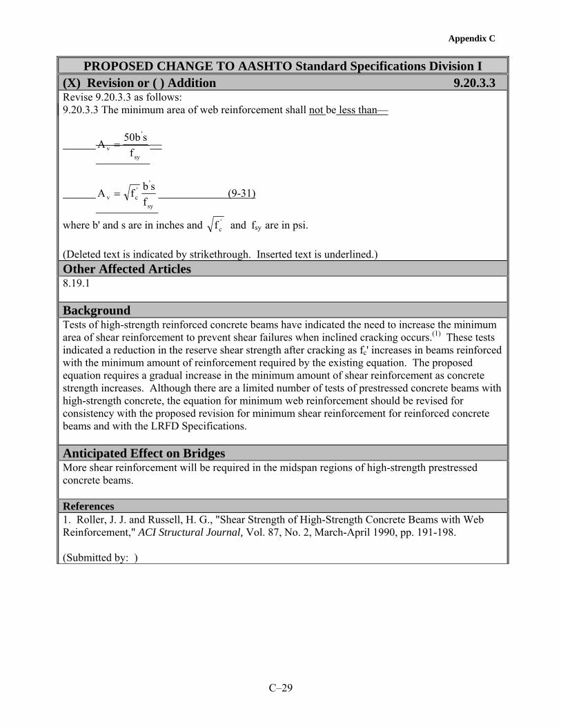
Appendix C
C–29
PROPOSED CHANGE TO AASHTO Standard Specifications Division I
(X) Revision or ( ) Addition 9.20.3.3 Revise 9.20.3.3 as follows: 9.20.3.3 The minimum area of web reinforcement shall not be less than—
sy
'
v fsb50A =
sy
''cv f
sbfA = (9-31)
where b' and s are in inches and andf 'c fsy are in psi.
(Deleted text is indicated by strikethrough. Inserted text is underlined.) Other Affected Articles 8.19.1 Background Tests of high-strength reinforced concrete beams have indicated the need to increase the minimum area of shear reinforcement to prevent shear failures when inclined cracking occurs.(1) These tests indicated a reduction in the reserve shear strength after cracking as fc' increases in beams reinforced with the minimum amount of reinforcement required by the existing equation. The proposed equation requires a gradual increase in the minimum amount of shear reinforcement as concrete strength increases. Although there are a limited number of tests of prestressed concrete beams with high-strength concrete, the equation for minimum web reinforcement should be revised for consistency with the proposed revision for minimum shear reinforcement for reinforced concrete beams and with the LRFD Specifications. Anticipated Effect on Bridges More shear reinforcement will be required in the midspan regions of high-strength prestressed concrete beams. References 1. Roller, J. J. and Russell, H. G., "Shear Strength of High-Strength Concrete Beams with Web Reinforcement," ACI Structural Journal, Vol. 87, No. 2, March-April 1990, pp. 191-198. (Submitted by: )


Appendix C
C–31
PROPOSED CHANGE TO AASHTO Standard Specifications Division I
(X) Revision or ( ) Addition 9.20.3.4 Revise 9.20.3.4 as follows: 9.20.3.4 The design yield strength of web reinforcement, fsy, shall not exceed 60,00075,000 psi. For design yield strengths in excess of 60,000 psi, fsy shall be the stress corresponding to a strain of 0.35 percent. (Deleted text is indicated by strikethrough. Inserted text is underlined.) Other Affected Articles 8.3.3 Background High strength steels are especially effective in high-strength prestressed concrete members with narrow web widths. The effectiveness of using higher yield strengths has been demonstrated in several research projects.(1-7) Measured shear strengths of beams have exceeded calculated design strengths even when measured yield strengths of reinforcement greater than 60 ksi were used in the calculations. Anticipated Effect on Bridges More economical bridge girders. References 1. Griezic, A., Cook, W. D., and Mitchell, D., "Tests to Determine Performance of Deformed Welded Wire Fabric Stirrups," ACI Structural Journal, Vol. 91, No. 2, March-April 1994, pp. 211-220. 2. Shahawy, M. A. and Batchelor, B. deV., "Shear Behavior of Full-Scale Prestressed Concrete Girders: Comparison Between AASHTO Specifications and LRFD Code," PCI Journal, Vol. 41, No. 3, May-June 1996, pp. 48-62. 3. "Reader Comments on Shear Behavior of Full-Scale Prestressed Concrete Girders: Comparison Between AASHTO Specifications and LRFD Code," PCI Journal, Vol. 42, No. 3, May-June 1997, pp. 72-93. 4. Ma, Z. and Tadros, M. K., "Simplified Method For Shear Design Based on AASHTO Load and Resistance Factor Design Specifications," Paper No. 99-0266, Transportation Research Record 1688, Transportation Research Board, Washington, D.C., November 1999, pp. 10-20. 5. Ma, Z., Tadros, M. K., and Baishya, M., "Shear Behavior of Pretensioned High Strength Concrete Bridge I-Girders," ACI Structural Journal, Vol. 97, No. 1, January-February 2000, pp. 185-192. 6. Tadros, M. K. and Yehia, S., "Shear of Design of High Strength Concrete NU I-Girders," Final Report for Nebraska Department of Roads, December 2001. 7. Bruce, R. N., Russell, H. G., and Roller, J. J., "Fatigue and Shear Behavior of HPC Bulb-Tee Girders," Louisiana Transportation Research Center, Baton Rouge, LA, to be published.

Appendix C
C–32
(Submitted by: )

Appendix C
C–33
PROPOSED CHANGE TO AASHTO Standard Specifications Division I
( ) Revision or (X) Addition 9.23 Revise 9.23 Concrete Strength at Stress Transfer as follows: Unless otherwise specified, stress shall not be transferred to concrete until the compressive strength of the concrete as indicated by test cylinders, cured by methods identical with the curing of the members, in accordance with Division II, Article 8.5.7.5, is at least 4,000 psi for pretensioned members (other than piles) and 3,500 psi for post-tensioned members and pretensioned piles. (Deleted text is indicated by strikethrough. Inserted text is underlined.) Other Affected Articles Division II Article 8.5.7.5 Background Since high-strength concrete generates more heat of hydration than conventional strength concrete, it is important that test cylinders be cured at the same temperature as the member.(1,2) Curing conditions for test cylinders are defined in proposed additions to Division II. Anticipated Effect on Bridges Provides a more realistic measure of the compressive strength of the concrete in the member. References 1. High Performance Concrete, Compact Disc, Federal Highway Administration, Version 3.0, February 2003. 2. Meyers, J. J. and Carrasquillo R. L., "Production and Quality Control of High Performance Concrete in Texas Bridge Structures," Center for Transportation Research, The University of Texas at Austin, Research Report 580/589-1, 2000, 553 pp. (Submitted by: )


Appendix C
C–35
PROPOSED CHANGE TO AASHTO Standard Specifications Division II
(X) Revision or (X) Addition 8.2 Revise 8.2.2 Normal Weight Concrete and add two new classes of high performance concrete to Table 8.2: 8.2.2 Normal Weight Concrete Eight Ten classes of normal weight concrete are provided for in these specifications as listed in Table 8.2.
Minimum Cement Content
Maximum Water/
Cementitious Materials
Ratio
Air Content Range
Size of Coarse
Aggregate Per AASHTO
M 43
Specified Compressive
Strength (28 Days)
Class of Concrete
Pounds per CY Lbs per Lb Percent Square
Openings (lb/in.2)
P(HPC) —c
0.40
As specified in the contract ≤ 3/4 in
> 6,000 as specified in the contract
A(HPC) —c 0.45 As specified in the contract —c 4,000
c Minimum cementitious materials content and coarse aggregate size to be selected to meet other performance criteria specified in the contract. (Deleted text is indicated by strikethrough. Inserted text is underlined.) Other Affected Articles 8.4.3 Background With high performance concrete, it is desirable that the specifications be performance based. The introduction of two new classes of concrete is a move in this direction. Class P(HPC) is intended for use in prestressed concrete members with a specified concrete compressive strength greater than 6000 psi (41 MPa). Class A (HPC) is intended for use in cast-in-place construction where performance criteria in addition to concrete compressive strengths are specified. Other criteria might include shrinkage, chloride permeability, freeze-thaw resistance, deicer scaling resistance, abrasion resistance, or heat of hydration.(1,2) The proposed change to the heading of the third column will affect all classes of concrete listed in the existing table and makes the table more consistent with the state-of-the-art of concrete technology. The requirement to measure concrete strength at 28 days has been deleted because later ages are more relevant for high-strength concrete. The designer should specify the age based on the anticipated strength development of the concrete and the intended application.

Appendix C
C–36
For both classes of concrete, a minimum cement content is not included since this should be selected by the producer based on the specified performance criteria. A maximum water/cementitious materials has been retained to be consistent with the existing water/cement ratios for Class P and Class A concretes. For Class P(HPC) concrete, a maximum size of coarse aggregate is specified since it is difficult to achieve the higher concrete compressive strengths with aggregates larger than 3/4 in (19 mm). For Class A(HPC) concrete, the maximum aggregate size should be selected by the producer based on the specified performance criteria. Anticipated Effect on Bridges Encourage the use of high performance concrete with higher strength, lower permeability, or other performance criteria. References 1. Goodspeed, C. H., Vanikar, S., and Cook, R., "High Performance Concrete Defined for Highway Structures," Concrete International, Vol. 18, No. 2, February 1996, pp. 62-67. 2. High Performance Concrete, Compact Disc, Federal Highway Administration, Version 3.0, February 2003. (Submitted by: )

Appendix C
C–37
PROPOSED CHANGE TO AASHTO Standard Specifications Division II
(X) Revision or (X) Addition 8.3.1 Revise 8.3.1 Cements as follows: 8.3.1 Cements Portland Cements shall conform to the requirements of AASHTO M 85 (ASTM C 150) and Blended Hydraulic Cements shall conform to the requirements of AASHTO M 240 (ASTM C 595) or ASTM C 1157. For Type IP Portland–pozzolan cement, the pozzolan constituent shall not exceed 20 percent of the weight of the blend and the loss on ignition of the pozzolan shall not exceed 5 percent.
Except for Class P(HPC) and Class A(HPC) or when Unless otherwise specified, only Type I, II, or III Portland Cement, Types IA, IIA, IIIA Air Entrained Portland Cement or Types IP or IS Blended Hydraulic Cements shall be used. Types IA, IIA, and IIIA cements may be used only in concrete where air entrainment is required.
Low-alkali cements conforming to the requirements of AASHTO M 85 for low-alkali cement shall be used when specified or when ordered by the Engineer as a condition of use for aggregates of limited alkali-silica reactivity.
Unless otherwise permitted, the product of only one mill of any one brand and type of cement shall be used for like elements of a structure that are exposed to view, except when cements must be blended for reduction of any excessive air-entrainment where air entraining cement is used. For Class P(HPC) and Class A(HPC), trial batches using all intended constituent materials shall be made prior to concrete placement to ensure that cement and admixtures are compatible. Changes in the mill, brand, or type of cement shall not be permitted without additional trial batches. (Deleted text is indicated by strikethrough. Inserted text is underlined.) Other Affected Articles None Background ASTM C 1157 is a standard performance specification for blended cements and should be included.(1) Restricting the cements to Types I, II, III, IA, IIA, IIIA, IP, or IS may prevent innovation and selection to enhance the performance of HPC. Interactions between cementitious material and chemical admixtures can cause incompatibility leading to premature stiffening, extended setting time, or inadequate air-void system. HPC may be very sensitive to the brand, type, and mill of origin of the cement. Studies have shown that changing the brand of cement can cause large differences in the hardened properties of HPC.(2)
Anticipated Effect on Bridges More choices, improved properties, and less problems in the field.

Appendix C
C–38
References 1. ASTM C 1157 Standard Performance Specification for Blended Hydraulic Cement. 2. ACI 363 Committee, "State-of-the-Art Report on High-Strength Concrete (ACI 363R-92)," American Concrete Institute, Farmington Hills, MI, 1992, 55 pp. (Submitted by: )

Appendix C
C–39
PROPOSED CHANGE TO AASHTO Standard Specifications Division II
( ) Revision or (X) Addition 8.3.5 Add a new article 8.3.5 and renumber subsequent articles. 8.3.5 Combined Aggregates Blends of fine and coarse aggregates shall conform to the requirements of AASHTO M XX1 (Deleted text is indicated by strikethrough. Inserted text is underlined.) Other Affected Articles Material specifications M 6, M 43, and M 80 Background A new specification on combined aggregates has been proposed and needs to be referenced. Combined aggregates enable the use of less water, cementitious materials, and paste leading to improved properties in the freshly mixed and hardened concrete. Anticipated Effect on Bridges Improved concrete properties. References None (Submitted by: )


Appendix C
C–41
PROPOSED CHANGE TO AASHTO Standard Specifications Division II
(X) Revision or ( ) Addition 8.3.7 Replace the first paragraph of 8.3.7 Mineral Admixtures as follows: 8.3.7 Mineral Admixtures Fly ash pozzolans and calcined natural pozzolans for use as mineral admixtures in concrete shall conform to the requirements of AASHTO M 295 (ASTM C 618). Mineral admixtures in concrete shall conform to the following requirements: Fly ash pozzolans and calcined natural pozzolans – AASHTO M 295 (ASTM C 618) Ground granulated blast-furnace slag – AASHTO M 302 (ASTM C 989) Silica fume – AASHTO M 307 (ASTM C 1240) (Deleted text is indicated by strikethrough. Inserted text is underlined.) Other Affected Articles 8.4.4 Background Slag and silica fume are widely used in HPC and need to be referenced. Anticipated Effect on Bridges More choices of materials. References None (Submitted by: )


Appendix C
C–43
PROPOSED CHANGE TO AASHTO Standard Specifications Division II
(X) Revision or ( ) Addition 8.4.1 Item No. 1 Revise 8.4.1.1 Responsibility and Criteria as follows: 8.4.1.1 Responsibility and Criteria The contractor shall design and be responsible for the performance of all concrete mixes used in structures. The mix proportions selected shall produce concrete that is sufficiently workable and finishable for all uses intended and shall conform to the requirements in Table 8.2 and all other requirements of this Section. For normal weight concrete the absolute volume method, such as described in American Concrete Institute Publication 211.1, shall be used in selecting mix proportions. For Class P(HPC) with fly ash, the method given in American Concrete Institute Guide 211.4 shall be permitted. For structural lightweight concrete, the mix proportions shall be selected on the basis of trial mixes with the cement factor rather than the water/cement ratio being determined by the specified strength using methods such as those described in American Concrete Institute Publication 211.2. The mix design shall be based on the specified properties. When strength is specified, select upon obtaining an average concrete strength sufficiently above the specified strength so that, considering the expected variability of the concrete and test procedures, no more than 1 in 10 strength tests will be expected to fall below the specified strength. Mix designs shall be modified during the course of the work when necessary to ensure compliance with strength and consistency requirements the specified fresh and hardened concrete properties. For Class P(HPC) and Class A(HPC), such modifications shall only be permitted after trial batches to demonstrate that the modified mix design will result in concrete that complies with the specified concrete properties. Item No. 2 Revise 8.4.1.2 Trial Batch Tests as follows: 8.4.1.2 Trial Batch Tests For classes A, A(AE), and P, P(HPC), and A(HPC) concrete, for lightweight concrete, and for other classes of concrete when specified or ordered by the Engineer, satisfactory performance of the proposed mix design shall be verified by laboratory tests on trial batches. The results of such tests shall be furnished to the Engineer by the contractor or the manufacturer of the precast elements at the time the proposed mix design is submitted. For mix design approval, the strengths of a minimum of five test cylinders taken from a trial batch shall average at least 800 psi greater than the specified strength. If materials and a mix design identical to those proposed for use have been used on other work within the previous year, certified copies of concrete test results from this work which indicate full compliance with these specifications may be substituted for such laboratory tests. If the results of more than 10 such strength tests are available from historical records for the past year, average strength for these tests shall be at least 1.28 standard deviations above the specified strength. The average values obtained from trial batches for the specified properties, such as strength shall exceed design values by a certain amount based on variability. For compressive strength, the required average strength used as a basis for selection of concrete proportions shall be determined in accordance with AASHTO M 241. (Deleted text is indicated by strikethrough. Inserted text is underlined.)

Appendix C
C–44
Other Affected Articles AASHTO M 241 Background Item No. 1 ACI Guide 211.4 describes selecting proportions for high-strength concrete with portland cement and fly ash.(1) In HPC, type, size, and shape of aggregate become important. Properties other than strength are also important in bridge structures. Any modification to the mixture proportions and ingredients must be tested using trial batches. Item No. 2 Properties other than strength are also included. Overstrength requirements are updated for all strength levels including high-strength concrete by referring to AASHTO M 241.(2,3) Revisions to AASHTO M 241 are also proposed. Anticipated Effect on Bridges More durable structures. Inclusion of high-strength concrete. References 1. ACI Committee 211, "Guide for Selecting Proportions for High-Strength Concrete with Portland Cement and Fly Ash (ACI 211.4)" American Concrete Institute, Farmington Hills, MI, 1993, 13 pp. 2. Cagley, J. R. "Changing from ACI 318-99 to ACI 318-02," Concrete International, American Concrete Institute, June 2001. 3. AASHTO M 241 Standard Specification for Concrete Made by Volumetric Batching and Continuous Mixing. (Submitted by: )

Appendix C
C–45
PROPOSED CHANGE TO AASHTO Standard Specifications Division II
( ) Revision or (X) Addition 8.4.3 Revise 8.4.3 Cement Content as follows: The minimum cement content shall be as listed in Table 8.2 or otherwise specified. For Class P(HPC), the total cementitious materials content shall be specified not to exceed 1,000 pounds per cubic yard of concrete. For other classes of concrete, Tthe maximum cement or cement plus mineral admixture content shall not exceed 800 pounds per cubic yard of concrete. The actual cement content used shall be within these limits and shall be sufficient to produce concrete of the required strength, and consistency, and performance. (Deleted text is indicated by strikethrough. Inserted text is underlined.) Other Affected Articles 8.2 Background Many high-strength concretes require a cementitious materials content in excess of 800 lb/yd3 (475 kg/m3).(1) A higher limit is, therefore, appropriate. Anticipated Effect on Bridges Facilitate the use of high-strength and high performance concrete. References 1. High Performance Concrete, Compact Disc, Federal Highway Administration, Version 3.0, February 2003. (Submitted by: )


Appendix C
C–47
PROPOSED CHANGE TO AASHTO Standard Specifications Division II
(X) Revision or ( ) Addition 8.4.4 Revise 8.4.4 Mineral Admixtures as follows: 8.4.4 Mineral Admixtures Mineral admixtures shall be used in the amounts specified. In addition,For all classes of concrete except P(HPC) and A(HPC), when either Types I, II, IV or V (AASHTO M 85) cements are used and mineral admixtures are neither specified nor prohibited, the Contractor will be permitted to replace up to 20 25 percent of the required Portland cement with a mineral admixture fly ash or other pozzolan conforming to AASHTO M 295, up to 50 percent of the required Portland cement with slag conforming to AASHTO M 302, or up to 10 percent of the required Portland cement with silica fume conforming to AASHTO M 307. When any combination of fly ash, slag, and silica fume are used, the Contractor will be permitted to replace up to 50 percent of the required Portland cement. However, no more than 25 percent shall be fly ash and no more than 10 percent shall be silica fume. The weight of the mineral admixture used shall be equal to or greater than the weight of the Portland cement replaced. In calculating the water/-cementitious materials ratio of the mix, the weight of cementitious materials shall be considered to be the sum of the weights of the Portland cement and the mineral admixtures. For Class P(HPC) and Class A(HPC) concrete, mineral admixtures (pozzolans or slag) shall be permitted to be used as cementitious material with portland cement in blended cements or as a separate addition at the mixer. The amount of mineral admixture shall be determined by trial batches. The water-cementitious materials ratio shall be the ratio of the weight of water to the total cementitious materials, including the mineral admixtures. The properties of the freshly mixed and hardened concrete shall comply with specified values. (Deleted text is indicated by strikethrough. Inserted text is underlined.) Other Affected Articles 8.3.7 Background Mineral admixtures are widely used in HPC today. These include fly ash, ground granulated blast-furnace slag, and silica fume. The use of these materials results in a concrete with a finer pore structure and, therefore, lower permeability. The proposed replacement percentages are based on those in ACI 318 for concrete exposed to deicing chemicals.(1) Trial batches are required with HPC to ensure that the specified properties are achieved. Anticipated Effect on Bridges Improved concrete for more durable structures. References 1. ACI Committee 318, Building Code Requirements for Structural Concrete (318-02) and Commentary (318R-02), American Concrete Institute, Farmington Hills, MI, 2002, 443 pp. (Submitted by: )


Appendix C
C–49
PROPOSED CHANGE TO AASHTO Standard Specifications Division II
(X) Revision or ( ) Addition 8.5.7.1 Revise 8.5.7.1 Tests as follows: 8.5.7.1 Tests A strength test shall consist of the average strength of at least two 6x12-in. or at least three 4x8-in. compressive strength test cylinders fabricated from material taken from a single randomly selected batch of concrete, except that, if any cylinder should show evidence of improper sampling, molding, or testing, said cylinder shall be discarded and the strength test shall consist of the strength of the remaining cylinder(s). A minimum of three cylinders shall be fabricated for each strength test when the specified strength exceeds 5,000 psi. (Deleted text is indicated by strikethrough. Inserted text is underlined.) Other Affected Articles AASHTO M 241 Background 4x8-in cylinders are commonly used for testing high-strength concrete and may exhibit higher variability.(1) For high-strength concrete, strength is more critical, and at least three cylinders are recommended for any size.(2) Anticipated Effect on Bridges Improved quality of concrete and more valid measurements of compressive strength. References 1. Ozyildirim, C., "4 x 8 inch Concrete Cylinders versus 6 x 12 inch Cylinders," VHTRC 84-R44, Virginia Transportation Research Council, Charlottesville, VA, May 1984, 25 pp. 2. ACI Committee 363, "Guide to Quality Control and Testing of High-Strength Concrete (ACI 363.2R-98)," American Concrete Institute, Farmington Hills, MI, 1998, 18 pp. (Submitted by: )


Appendix C
C–51
PROPOSED CHANGE TO AASHTO Standard Specifications Division II
(X) Revision or ( ) Addition 8.5.7.3 Revise 8.5.7.3 For Acceptance of Concrete as follows: 8.5.7.3 For Acceptance of Concrete For determining compliance of concrete with a specified 28-day strength, test cylinders shall be cured under controlled conditions as described in Article 9.3 of AASHTO T 23 and tested at the specified age of 28 days. Samples for acceptance tests for each class of concrete shall be taken not less than once a day nor less than once for each 150 cubic yards of concrete or once for each major placement. Except for Class P(HPC) and Class A(HPC) concrete, aAny concrete represented by a test thatwhich indicates a strength thatwhich is less than the specified 28-day compressive strength at the specified age by more than 500 psi will be rejected and shall be removed and replaced with acceptable concrete. Such rejection shall prevail unless either:
(1) The Contractor, at his or her expense, obtains and submits evidence of a type acceptable to the Engineer that the strength and quality of the rejected concrete is acceptable. If such evidence consists of cores taken from the work, the cores shall be obtained and tested in accordance with the standard methods of AASHTO T 24 (ASTM C 42) or,
(2) The Engineer determines that said concrete is located where it will not create an intolerable
detrimental effect on the structure and the Contractor agrees to a reduced payment to compensate the Department for loss of durability and other lost benefits.
For Class P(HPC) and Class A(HPC) concrete, any concrete represented by a test that indicates a strength that is less than the specified compressive strength at the specified age will be rejected and shall be removed and replaced with acceptable concrete. (Deleted text is indicated by strikethrough. Inserted text is underlined.) Other Affected Articles None Background Test ages other than 28 days are frequently specified for high-strength concrete.(1) The elimination of 28 days in this provision allows the use of other test ages. A goal of HPC is to provide concrete that meets the specification for the intended application. Accepting concrete that does not meet the specified compressive strength is not an acceptable practice for HPC. A reduced payment cannot compensate for a loss of durability and possible reduced service life. Anticipated Effect on Bridges Improved quality of concrete. References 1. High Performance Concrete, Compact Disc, Federal Highway Administration, Version 3.0, February 2003.

Appendix C
C–52
(Submitted by: )

Appendix C
C–53
PROPOSED CHANGE TO AASHTO Standard Specifications Division II
( ) Revision or (X) Addition 8.5.7.5 Revise 8.5.7.5 Steam and Radiant Heat-Cured Concrete as follows: 8.5.7.5 Precast Concrete Cured by the Waterproof Cover Method, Steam and or Radiant Heat Heat-Cured Concrete When a precast concrete member is cured by the waterproof cover method, steam, or radiant heat-cured, the compressive strength test cylinders made for any of the above purposes shall be cured under conditions similar to the member. Such concrete will shall be considered to be acceptable whenever a test indicates that the concrete has reached the specified 28-day compressive strength provided such strength is reached not more than 28 days after the member is cast no later than the specified age for the compressive strength. Test cylinders shall be cured by only one of the following methods: (1) For concrete with specified design compressive strengths less than or equal to 6,000 psi, test cylinders shall be stored next to the member and under the same covers such that the cylinders are exposed to the same temperature conditions as the member. (2) For all specified concrete strengths, test cylinders shall be match-cured in chambers in which the temperature of the chamber is correlated with the temperature in the member prior to release of the prestressing strands. Temperatures of the chamber and member shall be verified by use of temperature sensors in the chamber and member. Unless specified otherwise, temperature sensors in I-beams shall be located at the center of gravity of the bottom flange. For other members, the temperature sensors shall be located at the center of the thickest section. The location shall be specified on the drawings. After release of the prestressing strands, cylinders shall be stored in a similar temperature and humidity environment as the member. (Deleted text is indicated by strikethrough. Inserted text is underlined.) Other Affected Articles Division I, 9.23 Background Research on several FHWA-State high performance concrete showcase projects has shown that the strength of quality control cylinders is affected by the curing temperatures that the cylinders experience.(1,2) A high initial curing temperature accelerates the strength gain at early ages but results in a slower strength gain at later ages. Consequently, a test cylinder that experiences a different temperature history from the member that it represents does not truly represent the strength of the concrete in the member either at an age corresponding to release of the strands or at later ages. This effect becomes more significant with high-strength concrete because of the higher cementitious materials content and higher heat of hydration. Placing the test cylinders under the same covers as the member has proved to be an acceptable method for conventional strength concretes. However, for high-strength concretes, match curing is essential if realistic values of strength are to be measured.(3) The proposed changes allow the traditional method to be used for conventional strength concretes while requiring match curing for high-strength concretes and allowing match curing for conventional strength concretes.

Appendix C
C–54
Anticipated Effect on Bridges Provides a more realistic measure of the compressive strength of concrete in the member. References 1. High Performance Concrete, Compact Disc, Federal Highway Administration, Version 3.0, February 2003. 2. Meyers, J. J. and Carrasquillo R. L., "Production and Quality Control of High Performance Concrete in Texas Bridge Structures," Center for Transportation Research, The University of Texas at Austin, Research Report 580/589-1, 2000, 553 pp. 3. Russell, H. G., "Consider Match Curing for High-Strength Precast," Concrete Products, Vol. 102, No. 7, July 1999, pp. 117-118. (Submitted by: )

Appendix C
C–55
PROPOSED CHANGE TO AASHTO Standard Specifications Division II
(X) Revision or ( ) Addition 8.6.4.1 Revise 8.6.4.1 Protection During Cure as follows: 8.6.4.1 Protection During Cure When there is a probability of air temperatures below 35oF during the cure period, the Contractor shall submit for approval by the Engineer prior to concrete placement, a cold weather concreting and curing plan detailing the methods and equipment which will be used to assure ensure that the required concrete temperatures are maintained. The concrete shall be maintained at a temperature of not less than 45oF for the first six days after-placement except that when pozzolans or slag are cement or fly ash cement is used, this period shall be as follows:
Percentage of Cement Replaced, by Weight, With
Pozzolans Slag
Required Period of Controlled Temperature
10% 25% 8 Ddays
11-15% 26-35% 9 Days
16-20% 36-50% 10 Days The above requirement for an extended period of controlled temperature may be waived if a compressive strength of 65 percent of the specified 28-day design strength is achieved in 6 days using site-cured cylinders or the match-curing system or the maturity method. When the percentage of cement replacement is larger than the values listed above or when combinations of materials are used as cement replacement, the required period of controlled temperature shall be at least 6 days and shall continue until a compressive strength of 65 percent of the specified design strength is achieved using site-cured cylinders or the match-curing system or the maturity method. If external heating is employed, the heat shall be applied and withdrawn gradually and uniformly so that no part of the concrete surface is heated to more than 90oF or caused to change temperature by more than 20oF in 8 hours. When requested by the Engineer, the Contractor shall provide and install two maximum-minimum type thermometers at each structure site. Such thermometers shall be installed as directed by the Engineer so as to monitor the temperature of the concrete and the surrounding air during the cure period. (Deleted text is indicated by strikethrough. Inserted text is underlined.) Other Affected Articles None Background The current provision only addresses pozzolans up to a cement replacement of 20 percent and needs to be more general. Instead of fixed periods of controlled temperature, the match-curing system or maturity method should be allowed. Both methods can be effective with HPC.

Appendix C
C–56
Anticipated Effect on Bridges The changes allow for a wider range of cement replacements and optional methods to reduce the required period of controlled temperature. The latter will allow for faster bridge construction. References None (Submitted by: )

Appendix C
C–57
PROPOSED CHANGE TO AASHTO Standard Specifications Division II
(X) Revision or ( ) Addition 8.6.6 and 8.6.7 Item No. 1 Revise 8.6.6 Concrete Exposed to Salt Water as follows: 8.6.6 Concrete Exposed to Salt Water Unless otherwise specifically provided, concrete for structures exposed to salt or brackish water shall comply with the requirements of Class A(HPC) concrete be Class S for concrete placed under water and Class A for other work. Such concrete shall be mixed for a period of not less than 2 minutes and the water content of the mixture shall be carefully controlled and regulated so as to produce concrete of maximum impermeability. The concrete shall be thoroughly consolidated as necessary to produce maximum density and a complete lack of rock pockets. Unless otherwise indicated on the plans, the clear distance from the face of the concrete to the reinforcing steel shall be not less than 4 inches. No construction joints shall be formed between levels of extreme low water and extreme high water or the upper limit of wave action as determined by the Engineer. Between these levels the forms shall not be removed, or other means provided, to prevent salt water from coming in direct contact with the concrete for a period of not less than 30 days after placement. Except for the repair of any rock pockets and the plugging of form ties holes, the original surface as the concrete comes from the forms shall be left undisturbed. Special handling shall be provided for precast members to avoid even slight deformation cracks. Item No. 2 Revise 8.6.7 Concrete Exposed to Sulfate Soils or Water as follows: 8.6.7 Concrete Exposed to Sulfate Soils or Sulfate Water When the special provisions identify the area as containing sulfate soils or sulfate water, the concrete that will be in contact with such soil or water shall be Class A(HPC) and shall be mixed, placed, and protected from contact with soil or water as required for concrete exposed to salt water except that the protection period shall be not less than 72 hours. (Deleted text is indicated by strikethrough. Inserted text is underlined.) Other Affected Articles None Background HPC with low permeability are essential to provide the needed protection for concrete exposed to salt or sulfate solutions.(1) Class A(HPC) is intended for these applications. Anticipated Effect on Bridges Provide a lower permeability concrete. References 1. ACI Committee 222, "Corrosion of Metals in Concrete (ACI 222R-96)," American Concrete Institute, Farmington Hills, MI, 1996, 30 pp. (Submitted by: )


Appendix C
C–59
PROPOSED CHANGE TO AASHTO Standard Specifications Division II
(X) Revision or ( ) Addition 8.11.1 Revise 8.11.1 General as follows: All newly placed concrete shall be cured so as to prevent the loss of water by use of one or more of the methods specified herein. Except for Class A(HPC) concrete, Ccuring shall commence immediately after the free water has left the surface and finishing operations are completed. For Class A(HPC) concrete, water curing shall commence immediately after finishing operations are complete. If the surface of the concrete begins to dry before the selected cure method can be applied, the surface of the concrete shall be kept moist by a fog spray applied so as not to damage the surface. Curing by other than waterproof cover method with precast concrete or steam or radiant heat methods shall continue uninterrupted for 7 days except that when pozzolans in excess of 10 percent, by weight, of the Portland cement are used in the mix. When such pozzolans are used, the curing period shall be 10 days. For other than top slabs of structures serving as finished pavements, and Class A(HPC) concrete, the above curing periods may be reduced and curing terminated when test cylinders cured under the same conditions as the structure indicate that concrete strengths of at least 70 percent of that specified have been reached. When deemed necessary by the Engineer during periods of hot weather, water shall be applied to concrete surfaces being cured by the liquid membrane method or by the forms-in-place method, until the Engineer determines that a cooling effect is no longer required. Such application of water will be paid for as extra work. (Deleted text is indicated by strikethrough. Inserted text is underlined.) Other Affected Articles 8.11.4 and 8.13.4 Background Changes to 8.11.1 are needed to make it consistent with changes to 8.11.4 and 8.13.4.(1,2,3)
Anticipated Effect on Bridges Improved quality and durability of bridge decks. References 1. High Performance Concrete, Compact Disc, Federal Highway Administration, Version 3.0, February 2003. 2. Meyers, J. J. and Carrasquillo R. L., "Production and Quality Control of High Performance Concrete in Texas Bridge Structures," Center for Transportation Research, The University of Texas at Austin, Research Report 580/589-1, 2000, 553 pp. 3. HPC Bridge Views, Issue No. 15, May/June 2001. (Submitted by: )


Appendix C
C–61
PROPOSED CHANGE TO AASHTO Standard Specifications Division II
( ) Revision or (X) Addition 8.11.3.5 Revise 8.11.3.5 Steam or Radiant Heat Curing Method as follows: Item No. 1 Add the following at the end of the second paragraph: Steam curing or radiant heat curing shall be done under a suitable enclosure to contain the live steam or the heat. Steam shall be low pressure and saturated. Temperature recording devices shall be employed as necessary to verify that temperatures are uniform throughout the enclosure concrete and within the limits specified. Item No. 2 Revise the third paragraph as follows: The initial application of the steam or of the heat shall be from 2 to 4 hours after the final placement of concrete to allow the initial set of the concrete to take place. If retarders are used, the waiting period before application of the steam or of the radiant heat shall be increased to between 4 and 6 hours after placement not occur prior to initial set of the concrete except to maintain the temperature within the curing chamber above the specified minimum temperature. The time of initial set may be determined by the Standard Method of Test for "Time of Setting of Concrete Mixtures by Penetration Resistance," AASHTO T 197 (ASTM C 403)., and the time limits described above may then be waived. Item No. 3 Revise the fifth paragraph as follows: Application of live steam shall not be directed on the concrete or on the forms so as to cause localized high temperatures. During the initial application of live steam or of radiant heat, the ambient temperature within the curing enclosure concrete shall increase at an average rate not exceeding 40oF per hour until the curing temperature is reached. The maximum curing temperature within the enclosure concrete shall not exceed 160oF. The maximum temperature shall be held until the concrete has reached the desired strength. In discontinuing the steam application, the ambient air concrete temperature shall not decrease at a rate to exceed 40oF per hour until a temperature of 20oF above the temperature of the air to which the concrete will be exposed has been reached. Item No. 4 Revise the last paragraph as follows: Unless the ambient temperature is maintained above 60 oF, for prestressed members the transfer of the stressing force to the concrete shall be accomplished immediately after the steam curing or the heat curing has been discontinued. For prestressed members, the transfer of the stressing force to the concrete shall be accomplished immediately after the steam curing or heat curing has been discontinued. (Deleted text is indicated by strikethrough. Inserted text is underlined.) Other Affected Articles 8.2

Appendix C
C–62
Background Item No. 1 Since high-strength concrete generates significantly more heat than conventional strength concrete, it is important that concrete temperatures be monitored rather than temperatures throughout the enclosure.(1) Item No. 2 Since today's concretes may contain a wider variety of constituent materials than in the past, the current criteria of 2 to 4 hours or 4 to 6 hours may not be appropriate.(1) Measurement of time of set for the specific concrete is a more precise approach. Item No. 3 Research has shown that delayed ettringite formation (DEF) can occur in concretes subjected to high temperatures during curing and subsequently exposed to moisture. A maximum temperature of about 160 oF (71 oC) is generally recognized as an upper limit below which DEF is unlikely to occur. The PCI Quality Control Manual contains a recommendation that maximum concrete temperature should be limited to 158 oF (70 oC) if a known potential for alkali-silica reaction or DEF exists. Otherwise, the maximum concrete temperature is 180 oF (82 oC).(2) Item No. 4 The current provision allows the ambient temperature to fall as low as 60 oF (16 oC) before the strands are released. A large decrease in concrete and strand temperatures prior to release of the strands can result in vertical cracks in the member. This is more likely in deep members and high-strength concrete members. Immediate release of the strands after the steam or heat curing minimizes the likelihood of cracking.(3) Anticipated Effect on Bridges Improved quality of concrete in prestressed concrete girders and less cracking in bridge girders prior to transfer of the prestressing force. References 1. High Performance Concrete, Compact Disc, Federal Highway Administration, Version 3.0, February 2003. 2. Manual for Quality Control for Plants and Production of Structural Precast Concrete Products, MNL-116-99, Precast/Prestressed Concrete Institute, Chicago, IL, 1999. 3. Zia, P. and Caner, A., "Cracking in Large-Sized Long Span Prestressed Concrete AASHTO Girders," Center for Transportation Engineering Studies, North Carolina State University, October 1993, 87 pp. (Submitted by: )

Appendix C
C–63
PROPOSED CHANGE TO AASHTO Standard Specifications Division II
( ) Revision or (X) Addition 8.11.4 Add the following paragraph at the end of 8.11.4 Bridge Decks: When Class A(HPC) concrete is used in bridge decks, water cure shall be applied immediately after the finishing of any portion of the deck is complete and shall remain in place for a minimum period of 7 days irrespective of concrete strength. If conditions prevent immediate application of the water cure, an evaporation retardant shall be applied immediately after completion of finishing or fogging shall be used to maintain a high relative humidity above the concrete to prevent drying of the concrete surface. Following the water cure period, liquid membrane curing compound may be applied to extend the curing period. (Deleted text is indicated by strikethrough. Inserted text is underlined.) Other Affected Articles 8.11.1 Background High performance concrete tends to have very little bleed water, especially when a low water-cementitious materials ratio is used with mineral admixtures. As a result, the evaporation protection of the bleed water on the fresh concrete is lost. The most effective way to protect the concrete is by application of water cure as soon as screeding or tining of the concrete is complete and no later than 15 minutes after the concrete is placed in any portion of the deck.(1) If this is not possible, the next best alternative is to prevent or reduce moisture loss from the concrete until the water cure can be applied. In the water cure method, the concrete surface is kept continuously wet. The most appropriate method is to cover the deck with materials such as cotton mats, multiple layers of burlap, or other materials that do not discolor or damage the concrete surface and to keep these materials continuously and thoroughly wet. The water cure needs to continue for a minimum of 7 days irrespective of concrete strength. The use of a curing compound after the water cure extends the curing period while allowing the contractor to have access to the bridge deck. Note that 8.11.1 requires 10 days curing when more than 10 percent pozzolans are used. Anticipated Effect on Bridges Improved quality and durability of bridge decks. References 1. HPC Bridge Views, Issue No. 15, May/June 2001. (Submitted by: )


Appendix C
C–65
PROPOSED CHANGE TO AASHTO Standard Specifications Division II
(X) Revision or ( ) Addition 8.13.4 Revise 8.13.4 Curing as follows: Unless otherwise permitted, precast members shall be cured by either the water method, waterproof cover method, or the steam or radiant heat method. The use of insulated blankets is permitted with the waterproof cover method. When the waterproof cover method is used, the air temperature beneath the cover shall not be less than 50oF and live steam or radiant heat may be used to maintain the temperature above the minimum value. The maximum concrete temperature during the curing cycle shall not exceed 160oF. The waterproof cover shall remain in place until such time as the compressive strength of the concrete reaches the strength specified for detensioning or stripping. (Deleted text is indicated by strikethrough. Inserted text is underlined.) Other Affected Articles 8.11.1 Background High-strength concretes contain more cementitious material than used in conventional strength concrete.(1) Consequently, the heat generated during hydration is greater and sufficient heat can be generated to develop the compressive strength required for detensioning or stripping without the use of steam or radiant heating.(2) The new wording permits self-curing with or without insulated blankets by modifying the waterproof cover method. The revision also refers to concrete temperature rather than the enclosure temperature. Anticipated Effect on Bridges Reduce cost of girders since energy for heating is not required. References 1. High Performance Concrete, Compact Disc, Federal Highway Administration, Version 3.0, February 2003. 2. Meyers, J. J. and Carrasquillo R. L., "Production and Quality Control of High Performance Concrete in Texas Bridge Structures," Center for Transportation Research, The University of Texas at Austin, Research Report 580/589-1, 2000, 553 pp. (Submitted by: )


D–1
APPENDIX D—PROPOSED REVISIONS TO THE AASHTO LRFD BRIDGE DESIGN SPECIFICATIONS
TABLE OF CONTENTS
SECTION PAGE
3.5.1-1 Dead Loads .....................................................................................................................D–3
5.1 Scope.....................................................................................................................................D–5
5.3 Notation.................................................................................................................................D–7
C5.4.1 General ............................................................................................................................D–9
5.4.2.1 Compressive Strength ...................................................................................................D–11
C5.4.2.1-1 Concrete Mix Characteristics by Class ...................................................................D–13
5.4.2.3 Shrinkage and Creep .....................................................................................................D–15
5.4.2.4 Modulus of Elasticity....................................................................................................D–21
5.4.2.6 Modulus of Rupture ......................................................................................................D–23
5.4.6.2 Size of Ducts .................................................................................................................D–27
5.5.4.1 Strength Limit State—General and 5.9.4.1.1 Stress Limits for Concrete— Compression Stresses ......................................................................................................D–29
5.7.1 Assumptions for Service and Fatigue Limit States..........................................................D–31
5.8.2.8 Design and Detailing Requirements .............................................................................D–33
5.9.5.1,2,3 Loss of Prestress .....................................................................................................D–37
5.9.5.4 Refined Estimates of Time-Dependent Losses .............................................................D–49
5.12.2 Alkali-Silica Reactive Aggregates.................................................................................D–57
5.13.4.4.1 Pile Dimensions .......................................................................................................D–59


Appendix D
D–3
20XX AGENDA ITEM (proposed to T-10)
(X) Revision or ( ) Addition ( ) SI ( ) US (X) both versions LRFD 3.5.1-1 Item No. 1 Revise the unit weight of concrete in Table 3.5.1-1 as follows: Plain Concrete Lightweight 0.110 KCF Sand-Lightweight 0.120 KCF Normal Weight fc' ≤ 5.0 KSI 0.150 KCF 0.145 KCF 5.0 < fc' ≤ 15.0 KSI 0.140 + 0.001 fc' KCF Item No. 2 Revise C3.5.1 as follows: Table 1 provides traditional unit weights. The unit weight of granular materials depends upon the degree of compaction and water content. The unit weight of concrete is primarily affected by that the unit weight of the aggregate, which varies by geographical location, and design and increases with concrete compressive strength. The unit weight of reinforced concrete is generally taken as 0.005 KCF greater than the unit weight of plain concrete. The values provided for wood include the weight of mandatory preservatives. The weight of transit rails, etc., is to be used only for preliminary design. Item No. 3 Add the following to 3.3 Notation 3.3.1 General fc' = specified compressive strength of concrete for use in design (KSI) (3.5.1) (Deleted text is indicated by strikethrough. Inserted text is underlined.) Other Affected Articles 5.4.2.4 Background
Variation of unit weight with concrete compressive strength.
0.000
0.020
0.040
0.060
0.080
0.100
0.120
0.140
0.160
0.0 2.5 5.0 7.5 10.0 12.5 15.0
Compressive Strength f'c, KSI
Unit Weightwc, KCF
wc = 0.140 + 0.001f'c

Appendix D
D–4
Analysis of data from the FHWA Showcase projects and other sources indicates a trend that the unit weight of concrete increases as concrete strength increases.(1,2,3) Unit weights range from about 0.140 to 0.155 KCF (2.24 to 2.48 Mg/m3) with an average increase of about 0.001 KCF for every 1.0 KSI increase in compressive strength (2.3 kg/m3 for every 1 MPa). The proposed change recognizes this increase and differentiates between the unit weight of plain and reinforced concrete. Anticipated Effect on Bridges More precise calculation of dead load. References 1. High Performance Concrete, Compact Disc, Federal Highway Administration, Version 3.0, February 2003. 2. Burg, R. G. and Ost, B. W., "Engineering Properties of Commercially Available High-Strength Concretes," PCA Research and Development Bulletin RD104T, Portland Cement Association, Skokie, IL, 1992. 3. Burg, R. G. and Fiorato, A. E., "High-Strength Concrete in Massive Foundation Elements," PCA Research and Development Bulletin RD117, Portland Cement Association, Skokie, IL, 1999. (Submitted by: )

Appendix D
D–5
20XX AGENDA ITEM (proposed to T-10)
(X) Revision or ( ) Addition ( ) SI ( ) US (X) both versions LRFD 5.1 In 5.1 Scope, revise first paragraph as follows: The provisions in this section apply to the design of bridge and retaining wall components constructed of normal density or lightweight concrete and reinforced with steel bars, welded wire fabric reinforcement, and/or prestressing strands, or bars, or wires. The provisions are based on concrete strengths varying from 2.4 KSI to 10.0 KSI, except as noted. (Deleted text is indicated by strikethrough. Inserted text is underlined.) Other Affected Articles 5.4.2.1 Background 1. Both welded wire fabric reinforcement and prestressing wire are used in concrete members. Article 5.11 already addresses the development, anchorage, and splices of welded wire fabric. 2. Revisions are being proposed that will increase the maximum compressive strength for which some provisions are applicable. Anticipated Effect on Bridges Recognize the use of these materials in bridge members. References None (Submitted by: )


Appendix D
D–7
20XX AGENDA ITEM (proposed to T-10)
(X) Revision or ( ) Addition ( ) SI ( ) US (X) both versions LRFD 5.3 Revise 5.3 Notation for fc' as follows: fc' = specified compressive strength of concrete for use in design at 28 days, unless another age is specified (KSI) (5.4.2.1). (Deleted text is indicated by strikethrough. Inserted text is underlined.) Other Affected Articles None Background For the design purposes of section 5, the concrete age is not important. The designer should specify the age based on the anticipated strength development of the concrete and the intended application. Anticipated Effect on Bridges Allow more economical construction by avoiding strength developments that are not required for the intended application. References None (Submitted by: )


Appendix D
D–9
20XX AGENDA ITEM (proposed to T-10)
(X) Revision or (X) Addition ( ) SI ( ) US (X) both versions C5.4.1 In C5.4.1, revise second paragraph as follows: Occasionally, it may be appropriate to use materials other than those included in the AASHTO LRFD Bridge Construction Specifications; for example, when concretes are modified to obtain very high strengths through the introduction of special admixtures materials, such as: • Silica fume, • Cements other than Portland or blended hydraulic cements, • Proprietary high early strength cements, and • Ground granulated blast-furnace slag, and • Other types of reinforcing materials. In these cases the specified properties of such materials should be established by a specified testing program measured using the testing procedures defined in the contract documents. (Deleted text is indicated by strikethrough. Inserted text is underlined.) Other Affected Articles AASHTO LRFD Bridge Construction Specifications 8.3.7 Background 1. Ground granulated blast-furnace slag has been added to the list since it is used in HPC in bridge construction and is currently not covered in the Bridge Construction Specifications.(1) 2. The last paragraph has been revised to identify where the tests are defined. Anticipated Effect on Bridges Allow the use of ground granulated blast-furnace slag. References 1. High Performance Concrete, Compact Disc, Federal Highway Administration, Version 3.0, February 2003. (Submitted by: )


Appendix D
D-11
20XX AGENDA ITEM (proposed to T-10)
(X) Revision or (X) Addition ( ) SI ( ) US (X) both versions 5.4.2.1 Item No. 1. In 5.4.2.1 Compressive Strength, revise second paragraph as follows: Design Cconcrete strengths above 10.0 KSI shall be used only when allowed by specific articles or when physical tests are made to establish the relationships between the concrete strength and other properties. Specified cConcrete with strengths below 2.4 KSI at 28 days should not be used in structural applications. Item No. 2 In 5.4.2.1 Compressive Strength, revise the sixth paragraph as follows: The sum of Portland cement and other cementitious materials shall be specified not to exceed 800 PCY except for Class P(HPC) where the sum of portland cement and other cementitious materials shall be specified not to exceed 1000 PCY. (Deleted text is indicated by strikethrough. Inserted text is underlined.) Other Affected Articles Item No. 1 All those that reference strengths greater than 10.0 KSI Item No. 2 Table C5.4.2.1-1 Background Item No. 1 Ready-mixed concretes with actual compressive strengths in excess of 10 KSI (70 MPa) have been available for many years. These strengths can now be achieved in precast, prestressed concrete. In three FHWA-sponsored HPC projects, strengths in excess of 10 KSI (70 MPa) were specified and successfully achieved.(1) Age of 28 days has been eliminated since concrete age is not important for use in design. Various revisions to other articles are being proposed. Where research has shown that existing articles or revised articles are applicable to concrete members with strengths in excess of 10 KSI (70 MPa), the use of higher strengths should be allowed without the need for more physical tests. Item No. 2 Many high-strength concretes require a cementitious materials content in excess of 800 PCY to achieve the specified strength.(1)
Anticipated Effect on Bridges Allow longer span lengths, wider girder spacings, or shallower sections through the use of higher strength concrete. References 1. High Performance Concrete, Compact Disc, Federal Highway Administration, Version 3.0, February 2003.

Appendix D
D-12
(Submitted by: )
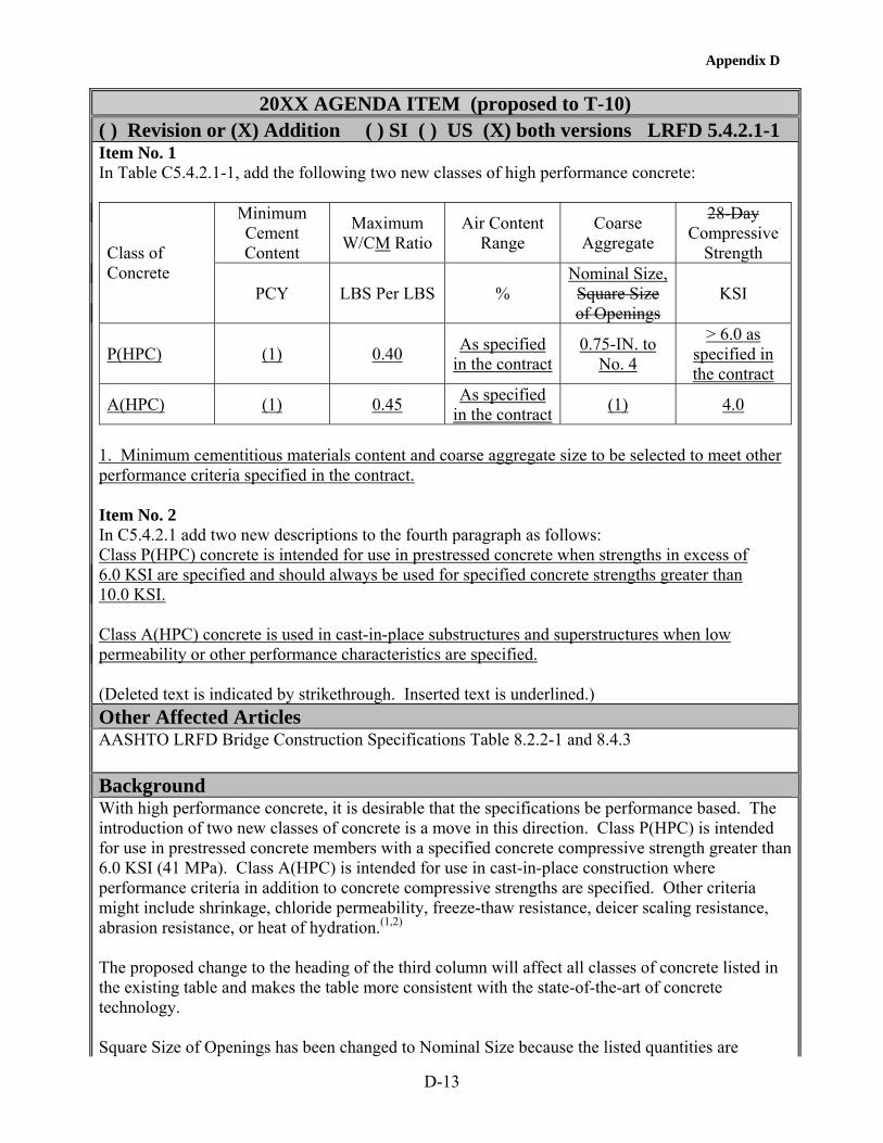
Appendix D
D-13
20XX AGENDA ITEM (proposed to T-10)
( ) Revision or (X) Addition ( ) SI ( ) US (X) both versions LRFD 5.4.2.1-1 Item No. 1 In Table C5.4.2.1-1, add the following two new classes of high performance concrete:
Minimum Cement Content
Maximum W/CM Ratio
Air Content Range
Coarse Aggregate
28-Day Compressive
Strength Class of Concrete
PCY LBS Per LBS % Nominal Size, Square Size of Openings
KSI
P(HPC) (1)
0.40
As specified in the contract
0.75-IN. to No. 4
> 6.0 as specified in the contract
A(HPC) (1) 0.45 As specified in the contract (1) 4.0
1. Minimum cementitious materials content and coarse aggregate size to be selected to meet other performance criteria specified in the contract. Item No. 2 In C5.4.2.1 add two new descriptions to the fourth paragraph as follows: Class P(HPC) concrete is intended for use in prestressed concrete when strengths in excess of 6.0 KSI are specified and should always be used for specified concrete strengths greater than 10.0 KSI. Class A(HPC) concrete is used in cast-in-place substructures and superstructures when low permeability or other performance characteristics are specified. (Deleted text is indicated by strikethrough. Inserted text is underlined.) Other Affected Articles AASHTO LRFD Bridge Construction Specifications Table 8.2.2-1 and 8.4.3 Background With high performance concrete, it is desirable that the specifications be performance based. The introduction of two new classes of concrete is a move in this direction. Class P(HPC) is intended for use in prestressed concrete members with a specified concrete compressive strength greater than 6.0 KSI (41 MPa). Class A(HPC) is intended for use in cast-in-place construction where performance criteria in addition to concrete compressive strengths are specified. Other criteria might include shrinkage, chloride permeability, freeze-thaw resistance, deicer scaling resistance, abrasion resistance, or heat of hydration.(1,2) The proposed change to the heading of the third column will affect all classes of concrete listed in the existing table and makes the table more consistent with the state-of-the-art of concrete technology. Square Size of Openings has been changed to Nominal Size because the listed quantities are

Appendix D
D-14
aggregate sizes. The requirement to measure concrete strength at 28 days has been deleted because later ages are more relevant for high-strength concrete. The designer should specify the age based on the anticipated strength development of the concrete and the intended application. For both classes of concrete, a minimum cement content is not included since this should be selected by the producer based on the specified performance criteria. A maximum water/cementitious materials has been retained to be consistent with the existing water/cement ratios for Class P and Class A concretes. For Class P(HPC) concrete, a maximum size of coarse aggregate is specified since it is difficult to achieve the higher concrete compressive strengths with aggregates larger than 3/4 in (19 mm). For Class A(HPC) concrete, the maximum aggregate size should be selected by the producer based on the specified performance criteria. Anticipated Effect on Bridges Encourage the use of high performance concrete with higher strength, lower permeability, or other properties. References 1. Goodspeed, C. H., Vanikar, S., and Cook, R., "High Performance Concrete Defined for Highway Structures," Concrete International, Vol. 18, No. 2, February 1996, pp. 62-67. 2. High Performance Concrete, Compact Disc, Federal Highway Administration, Version 3.0, February 2003. (Submitted by: )

Appendix D
D-15
20XX AGENDA ITEM (proposed to T-10)
(X) Revision or ( ) Addition ( ) SI ( ) US (X) both versions LRFD 5.4.2.3 Item No. 1 Revise 5.4.2.3 as follows: 5.4.2.3 Shrinkage and Creep 5.4.2.3.1 General Values of shrinkage and creep, specified herein and in Articles 5.9.5.3 and 5.9.5.4, shall be used to determine the effects of shrinkage and creep on the loss of prestressing force in bridges other than segmentally constructed ones. These values in conjunction with the moment of inertia, as specified in Article 5.7.3.6.2, may be used to determine the effects of shrinkage and creep on deflections. The provisions of Article 5.4.2.3 shall be applicable for specified concrete strengths up to 15.0 KSI. In the absence of more accurate data, the shrinkage coefficients may be assumed to be 0.0002 after 28 days and 0.0005 after one year of drying. When mix-specific data are not available, estimates of shrinkage and creep may be made using the provisions of: Articles 5.4.2.3.2 and 5.4.2.3.3 or other acceptable prediction methods. • Articles 5.4.2.3.2 and 5.4.2.3.3, • The CEB-FIP model code, or • ACI 209. For segmentally constructed bridges, a more precise estimate shall be made, including the effect of: • Specific materials, • Structural dimensions, • Site conditions, and • Construction methods., and • Concrete age at various stages of erection. 5.4.2.3.2 Creep The creep coefficient may be taken as: ( ) =ψ itt, 118.0
itdfhcs tkkkk9.1 − (5.4.2.3.2-1)
( )( ) 6.0
6.0118.0
0.1012058.15.3
i
iifc tt
tttHkk
−+
−⎟⎠⎞
⎜⎝⎛ − −
for which: ks = 1.45 – 0.13(V/S) ≥ 1.0 (5.4.2.3.2-2) khc = 1.56 – 0.008H (5.4.2.3.2-3)
⎟⎟⎠
⎞⎜⎜⎝
⎛+
=
967.0
1'
cf f
k

Appendix D
D-16
'ci
f f15 k+
= (5.4.2.3.2-24)
⎟⎟⎠
⎞⎜⎜⎝
⎛+−
=tf461
tk 'ci
td (5.4.2.3.2-5)
where: H = relative humidity (%). In the absence of better information, H may be taken from Figure 5.4.2.3.3-1. ks = factor for the effect of the volume-to-surface ratio of the component specified in Figure 1 kf = factor for the effect of concrete strength khc = humidity factor for creep ktd = time development factor t = maturity of concrete (Day), defined as age of concrete between time of loading for creep
calculations, or end of curing for shrinkage calculations, and time being considered for analysis of creep or shrinkage effects.
ti = age of concrete when load is initially applied (Day) V/S = volume-to-surface ratio In the absence of better information, H may be taken from Figure 5.4.2.3.3-1. f'ci = specified compressive strength of concrete at time of prestressing for pretensioned members
and 28 days at time of initial loading for non-prestressed members. If concrete age at time of initial loading is unknown at design time, '
cif may be taken as 0.80 'cf (KSI)
(Figure 5.4.2.3.2-1 – Factor kc for Volume to Surface Ratio) In determining the maturity of concrete at initial loading, ti, one day of accelerated curing by steam or radiant heat may be taken as equal to seven days of normal curing. The surface area used in determining the volume to area ratio should include only the area that is exposed to atmospheric drying. For poorly ventilated enclosed cells, only 50 percent of the interior perimeter should be used in calculating the surface area. For pretensioned stemmed members (I-beams, T-beams, and box beams), with an average web thickness of 6 to 8 IN, the value of ks may be taken as 1.00. 5.4.2.3.3 Shrinkage For moist cured concretes devoid of shrinkage-prone aggregates, the strain due to shrinkage, shε , at time, t, may be taken as:
31051.00.35
−×⎟⎟⎠
⎞⎜⎜⎝
⎛+
−=εt
tkk hssh
3
tdfhsssh 1048.0kkkk −×−=ε (5.4.2.3.3-1) for which:

Appendix D
D-17
khs = (2.00 – 0.014 H) (5.4.2.3.3-2) where: t = drying time(Day) ks = size factor specified in Figure 2 khs = humidity factor specified in Figure 1 and Table 1 for shrinkage If the moist-cured concrete is exposed to drying before five days of curing have elapsed, the shrinkage as determined in Equation 1 should be increased by 20 percent. For steam-cured concrete devoid of shrinkage-prone aggregates,
31056.00.55
−×⎟⎟⎠
⎞⎜⎜⎝
⎛+
−=εt
tkk hssh (5.4.2.3.3-2)
Figure 5.4.2.3.3-1 – Annual Average Ambient Relative Humidity in Percent Figure 5.4.2.3.3-2 – Factor ks for Volume-to-Surface Ratio Table 5.4.2.3.3-1 – Factor kh for Relative Humidity
Average Ambient Relative Humidity % kh
40 1.43 50 1.29 60 1.14 70 1.00 80 0.86 90 0.43 100 0.00

Appendix D
D-18
Item No. 2 Revise C5.4.2.3 as follows: C5.4.2.3.1 Creep and shrinkage of concrete are variable properties that depend on a number of factors, some of which may not be known at the time of design. Without specific physical tests or prior experience with the materials, the use of the empirical methods referenced in these Specifications cannot be expected to yield results with errors less than ± 50 percent. C5.4.2.3.2 The methods of determining creep and shrinkage, as specified herein and in Article 5.4.2.3.3, are taken frombased on Huo et al. (2001), Al-Omaishi (2001), Tadros (2002), and Collins and Mitchell (1991). These methods are based on the recommendation of ACI Committee 209 as modified by additional recently published data. Other applicable references include Rusch et al. (1983), Bazant and Wittman (1982), and Ghali and Favre (1986). The creep coefficient is applied to the compressive strain caused by permanent loads in order to obtain the strain due to creep. Creep is influenced by the same factors as shrinkage, and also by: • Magnitude and duration of the stress, • Maturity of the concrete at the time of loading, and • Temperature of concrete. Creep shortening of concrete under permanent loads is generally in the range of 1.5 0.5 to 4.0 times the initial elastic shortening, depending primarily on concrete maturity at the time of loading. Figure 1 is based on the equation below (PCI 1977): The factors for the effects of volume-to-surface ratio are an approximation of the following formulas: For creep:
⎥⎦
⎤⎢⎣
⎡ +
⎥⎥⎥⎥
⎦
⎤
⎢⎢⎢⎢
⎣
⎡
+
+=
−
587.2e77.180.1
t45t
te26t
k)V/S(54.0)V/S(36.0
c (C5.4.2.3.2-1)
For shrinkage:
⎥⎦⎤
⎢⎣⎡ −
⎥⎥⎥⎥
⎦
⎤
⎢⎢⎢⎢
⎣
⎡
+
+=
923)V/S(941064
t45t
te26t
k)V/S(36.0
s (C5.4.2.3.2-2)
The maximum V/S ratio considered in the development of Figure 1 and Equations C1 and C2 was 6.0 IN. Ultimate creep and shrinkage are less sensitive to surface exposure than intermediate values at an early age of concrete. For accurately estimating intermediate deformations of such

Appendix D
D-19
specialized structures as segmentally constructed balanced cantilever box girders, it may be necessary to resort to experimental data or use the more detailed Equations C5.4.2.3.2-1 and C5.4.2.3.2-2. C5.4.2.3.3 Shrinkage of concrete can vary over a wide range from nearly nil if continually immersed in water to in excess of 0.0008 for thin sections made with high shrinkage aggregates and sections that are not properly cured. Shrinkage is affected by: • Aggregates characteristics and proportions, • Average humidity at the bridge site, • W/C ratio, • Type of cure, • Volume to surface area ratio of member, and • Duration of drying period. Large concrete members may undergo substantially less shrinkage than that measured by laboratory testing of smaller specimens of the same concrete. The constraining effects of reinforcement and composite actions with other elements of the bridge tend to reduce the dimensional changes in some components.
Figure 2 is based on the equation below (PCI 1977).
⎥⎦⎤
⎢⎣⎡ −
⎥⎥⎥⎥
⎦
⎤
⎢⎢⎢⎢
⎣
⎡
+
+=
923)(941064
45
26 )(36.0 V/S
tt
tet
kV/S
s (C5.4.2.3.3-1)
The maximum V/S ratio considered in the development of Figure 2 and Equation C1 was 6.0 IN. The values in Table 1 may be approximated by the following equations: • For H < 80%
70140 Hkh
−= (C5.4.2.3.3-2)
• For H > 80%
( )70
1003 Hkh−
= (C5.4.2.3.3-3)
Item No. 3 Add the following to Section 5 References: Huo, X. S., Al-Omaishi, N., and Tadros, M. K., "Creep, Shrinkage, and Modulus of Elasticity of High Performance Concrete," ACI Materials Journal, Vol. 98, No. 6, November-December 2001, pp. 440-449. Al-Omaishi, N., "Prestress Losses in High Strength Pretensioned Concrete Bridge Girders," Ph.D.
Appendix D
D-20
Dissertation, University of Nebraska-Lincoln, December 2001, 265 pp. Tadros, M. K., Al-Omaishi, N., Seguirant, S. P, and Gallt, J. G., "Prestress Losses in High Strength Concrete Bridge Girders," NCHRP 18-07 Final Report, August 2002. (Deleted text is indicated by strikethrough. Inserted text is underlined.) Other Affected Articles 5.9.5 Background Recent research has indicated that high-strength concrete undergoes less ultimate creep and shrinkage than conventional concrete.(1-3) Creep and shrinkage develop relatively more rapidly in higher strength concrete than conventional concrete. The revised formulas take these effects into account, yet produce comparable results to preceding formulas for a concrete strength at release, f’ci, of 4.0 KSI or a concrete strength at service of 5.0 KSI. Due to the high variability of creep and shrinkage and due to the limitation imposed on applicability of the methods presented herein, some of the correction factors (e.g. the relative humidity factor) were unified between creep and shrinkage, and some were simplified (e.g. the volume/surface ratio factor). All factors were reformulated such that they are equal to unity when average conditions exist, e.g. concrete strength at release = 4 KSI, H = 70 percent and V/S ratio = 3.5. The proposed formulas yield approximately the same results as the current formulas when f’ci = 0.8f’c = 4 KSI. The proposed revisions are the results of NCHRP Project 18-07.(3)
Anticipated Effect on Bridges More realistic results of prestress losses and deflections, especially when high-strength concrete is used. References 1. Huo, X. S., Al-Omaishi, N., and Tadros, M. K., "Creep, Shrinkage, and Modulus of Elasticity of High Performance Concrete," ACI Materials Journal, Vol. 98, No. 6, November-December 2001, pp. 440-449. 2. Al-Omaishi, N., "Prestress Losses in High Strength Pretensioned Concrete Bridge Girders," Ph. D. Dissertation, University of Nebraska-Lincoln, December 2001, 265 pp. 3. Tadros, M. K., Al-Omaishi, N., Seguirant, S. P, and Gallt, J. G., "Prestress Losses in High Strength Concrete Bridge Girders," NCHRP 18-07 Final Report, August 2002. (Submitted by: )

Appendix D
D-21
20XX AGENDA ITEM (proposed to T-10)
(X) Revision or ( ) Addition ( ) SI ( ) US (X) both versions LRFD 5.4.2.4 Item No. 1 Revise 5.4.2.4 as follows: 5.4.2.4 Modulus of Elasticity In the absence of more precisemeasured data, the modulus of elasticity, Ec, for concretes with unit weights between 0.090 and 0.155 KCF and specified compressive strengths up to 15.0 KSI may be taken as: Ec = 33,000 K1
'c
5.1c fw (5.4.2.4-1)
where: K1 = factor for type of aggregate to be taken as 1.0 unless determined by physical tests wc = unit weight of concrete (KCF) When the measured unit weight of concrete is unknown, wc for normal weight concrete may be taken as 0.140 + 0.001 fc' but not less than 0.145 KCF.
'cf = specified compressive strength of concrete (KSI)
Item No. 2 Add the following at the end of C5.4.2.4: Test data show that the modulus of elasticity of concrete is influenced by the stiffness of the aggregate. The factor K1 is included to allow the calculated modulus to be adjusted for different types of aggregate and local materials. Unless a value has been determined by physical tests, K1 should be taken as 1.0. Use of a measured K1 factor permits a more accurate prediction of modulus of elasticity and other values that utilize it. The value of K1 can be determined by measuring Ec, wc, and f'c for a range of concrete strengths using the same aggregates and then calculating the optimum value of K1 to fit the measured values. Test data shows that the unit weight of normal weight concrete increases by about 0.001 KCF for each 1.0 KSI increase in compressive strength. Item No. 3 In 5.3 Notation, add the following: K1 = correction factor for type of aggregate to be taken as 1.0 unless determined by physical tests (5.4.2.4). (Deleted text is indicated by strikethrough. Inserted text is underlined.) Other Affected Articles 3.5.1 All articles that include Ec (Changes are not needed.)

Appendix D
D-22
Background Using a significant amount of test data, NCHRP Project 18-07 identified that the accuracy of the existing equation for predicting modulus of elasticity can be improved by the proposed modifications.(1) A more accurate prediction of modulus of elasticity is needed in calculating prestress losses and camber of high-strength concrete girders as the values are larger than for conventional strength concrete girders. Anticipated Effect on Bridges More accurate prediction of prestress losses and camber. References 1. Tadros, M. K., Al-Omaishi, N., Seguirant, S. P, and Gallt, J. G., "Prestress Losses in High Strength Concrete Bridge Girders," NCHRP 18-07 Final Report, August 2002. (Submitted by: )

Appendix D
D-23
20XX AGENDA ITEM (proposed to T-10)
(X) Revision or ( ) Addition ( ) SI ( ) US (X) both versions LRFD 5.4.2.6 Item No. 1 Revise 5.4.2.6 as follows: 5.4.2.6 Modulus of Rupture Unless determined by physical tests, modulus of rupture, fr, in KSI, for specified concrete strengths up to 15.0 KSI may be taken as: · For normal weight concrete—
When used to calculate the cracking moment of a member in 5.7.3.4 and 5.7.3.6.2 or for any other calculation where a lower bound value is appropriate............0.24 '
cf When used to calculate the cracking moment of a member in 5.7.3.3.2 or for any other calculations where an upper bound value is appropriate .................0.37 '
cf
· For sand-lightweight concrete..........................................................0.20 'cf
· For all-lightweight concrete .............................................................0.17 'cf
When physical tests are used to determine modulus of rupture, the tests shall be performed in accordance with AASHTO T 97 "Standard Method of Test for Flexural Strength of Concrete (Using Simple Beam with Third-Point Loading)" and shall be performed on concrete using the same proportions and materials as specified for the structure. Item No. 2 Add the following to the beginning of C5.4.2.6: Data show that most modulus of rupture values are between 0.24 '
cf and 0.37 'cf . It is
appropriate to use the lower bound value when considering service load cracking. The purpose of the minimum reinforcement in article 5.7.3.3.2 is to assure that the nominal moment capacity of the member is at least 20 percent greater than the cracking moment. Since the actual MOR could be as much as 50 percent greater than 0.24 '
cf the 20 percent margin of safety could be lost.
Using an upper bound is more appropriate in this situation. The properties of higher strength concretes are particularly sensitive to the constitutive materials. If test results are to be used in design, it is imperative that tests be made using concrete with not only the same mix proportions, but also the same materials as the concrete used in the structure.
(Deleted text is indicated by strikethrough. Inserted text is underlined.) Other Affected Articles 5.7.3.3.2 (No change required) 5.7.3.4 (No change required) 5.7.3.6.2 (No change required) Background Item No. 1 The value of 0.24 '
cf has been traditionally used for modulus of rupture (MOR) for concrete. Data show that this value greatly underestimates the MOR at higher compressive strengths.

Appendix D
D-24
ACI 363 indicates that a value for MOR of 0.37 'cf could be used for concrete compressive
strengths from 3 to 12 KSI.(1) However, examination of other data shows that most MOR values fall between these two limits.(2-10) Thus, the AASHTO value of 0.24 '
cf appears to be an
appropriate lower bound while the ACI 363 value of 0.37 'cf appears to be an appropriate
upperbound. Since the cracking moment is directly proportional to the MOR, use of these values yields lower and upper limits of the cracking moment. It is appropriate to use the lower bound value of the MOR when considering service load stresses, serviceability (whether a member is cracked and possible crack widths), or deflections, where lower values of a cracking moment yield more critical quantities. However, the upper bound value is more appropriate for determining minimum amounts of reinforcement. The purpose of the minimum reinforcement in 5.7.3.3.2 is to assure that the nominal moment capacity of member is at least 20 percent greater than the cracking moment. If the cracking moment is too close to the nominal moment capacity, the beam could fail in a brittle manner. Since the data show that the actual MOR could be as much as 50 percent greater than the lower bound MOR, the actual cracking moment could be as much as 50 percent greater than that calculated using the lower bound MOR. This effectively removes the 20 percent margin of safety. Using the upper bound value of MOR alleviates this problem. The existing provisions of the code allow the use of measured values for the modulus of rupture in design calculations. The properties of higher strength concretes are particularly sensitive to the constitutive materials. In many specifications, structural concrete is specified by a class or type with given proportions. The actual constitutive materials are often specified in broad terms rather then being specified as specific materials. Thus, a given type or class of concrete could be made with any one of a number of different aggregates, cements or admixtures. However, a concrete made with crushed limestone will have different properties from a concrete with the same proportions but using a gravel aggregate especially at higher compressive strengths. If test results are to be used in design, it is imperative that tests be made using concrete with not only the same proportions, but the same materials as used in the actual structure. Anticipated Effect on Bridges This change provides a more reasonable estimate of the cracking moment, Mcr. The cracking moment is used to assess minimum reinforcement requirements for beams (5.7.3.3.2), to determine if crack control reinforcement is needed in slabs (5.7.3.4), and to determine the effective moment of inertia for deflection calculations (5.7.3.6.2). References 1. ACI Committee 363, "State-of-the-Art Report on High-Strength Concrete (ACI 363R-92)," American Concrete Institute, Farmington Hills, MI, 1992, 55 pp. 2. Price, W. H., "Factors Influencing Concrete Strength," Journal of the American Concrete Institute, Vol. 47, February 1951, pp. 417-432. 3. Walker, S. and Bloem, D. L., "Effect of Aggregate Size on Properties of Concrete," Journal of the American Concrete Institute, Vol. 57, No. 3, September 1960, pp. 283-98. 4. Zia, P., Leming, M. L., Ahmad, S., Schemmel, J. J., Elliot, R. P., and Naaman, A. E., Mechanical Behavior of High Performance Concrete, Vol. 1 - Summary Report, SHRP Report C-361, Strategic Highway Research Program, National Research Council, Washington, D. C., 1993.

Appendix D
D-25
5. Zia, P., Leming, M. L., Ahmad, S., Schemmel, J. J., and Elliot, R. P., Mechanical Behavior of High Performance Concrete, Vol. 2, - Production of High Performance Concrete SHRP Report C-362, Strategic Highway Research Program, National Research Council, Washington, D. C., 1993. 6. Zia, P., Ahmad, S., Leming, M. L., Schemmel, J. J., and Elliot, R. P., Mechanical Behavior of High Performance Concrete, Vol. 3 - Very Early Strength Concrete, SHRP Report C-363, Strategic Highway Research Program, National Research Council, Washington, D. C., 1993. 7. Zia, P., Ahmad, S., Leming, M. L., Schemmel, J. J., and Elliot, R. P., Mechanical Behavior of High Performance Concrete, Vol. 4 - High Early Strength Concrete, SHRP Report C-364, Strategic Highway Research Program, National Research Council, Washington, D. C., 1993. 8. Zia, P., Ahmad, S., Leming, M. L., Schemmel, J. J., and Elliot, R. P., Mechanical Behavior of High Performance Concrete, Vol. 5 - Very High Strength Concrete, SHRP Report C-365, Strategic Highway Research Program, National Research Council, Washington, D. C., 1993. 9. Khan, A. A., Cook, W. D., and Mitchell, D., "Tensile Strength of Low, Medium, and High-Strength Concretes at Early Ages," ACI Materials Journal, Vol. 93, No. 5, September-October 1996, pp. 487-493. 10. High Performance Concrete, Compact Disc, Federal Highway Administration, Version 3.0, February 2003. (Submitted by: )


Appendix D
D–27
20XX AGENDA ITEM (proposed to T-10)
(X) Revision or ( ) Addition ( ) SI ( ) US (X) both versions LRFD 5.4.6.2 Revise 5.4.6.2 Size of Ducts, as follows: The inside diameter of ducts shall be at least 0.25-IN larger than the nominal diameter of single bar or strand tendons. For multiple bar or strand tendons, the inside cross-sectional area of the duct shall be at least 2.0 times the net area of the prestressing steel with one exception where tendons are to be placed by the pull-through method, the duct area shall be at least 2.5 times the net area of the prestressing steel. The size of ducts shall not exceed 0.4 times the least gross concrete thickness at the duct. For precast, pretensioned concrete beams, this requirement may be waived if the clear cover to the duct is not less than 1.5 IN. (Deleted text is indicated by strikethrough. Inserted text is underlined.) Other Affected Articles None Background The limit on maximum duct diameter of 0.4 times web thickness is unnecessarily restrictive in spliced I-girders, where high-strength concrete is increasingly used in practice. Many bridges have already been constructed with 7-in (175-mm) thick webs using 15 0.6-in (15.2-mm) strand tendons.(1-4) The Esker Overhead Bridge had 6-in (152-mm) thick web I-girders and 12 0.6-in (15.2-mm) strand tendons. Most of these bridges do not meet the 0.4 limit provision. The bridges have been performing satisfactorily. In all cases, the minimum web width has been set as the sum of twice the minimum concrete cover plus two stirrup bar diameters plus one duct diameter. The previous requirement of duct diameter not exceeding 0.4 web width is based on segmental box girder construction where the entire bridge cross section consists of two or three webs and where the spans are relatively large. Precast, prestressed I-girders are plant produced and the cross section of the bridge generally consists of at least four I-girders. Application of the 0.4 rule to spliced I-girders unnecessarily increases the web width and therefore the weight of the girder. This considerably impairs the cost-effectiveness of spliced I-girder systems as they become increasingly popular. Anticipated Effect on Bridges The proposed revision brings consistency between the LRFD Specifications and practice. It encourages more utilization of high-strength spliced girder bridges without designers having to supercede the requirements of this section. References 1. "State-of-the-Art Report of Spliced Girder Bridges," PCI, 1994, 134 pp. 2. Janssen, H. H. and Spaans, L., "Record Span Spliced Bulb-Tee Girders Used in Highland View Bridge," PCI Journal, Vol. 39, No. 1, January/February 1994, pp. 12-19. 3. Fitzgerald, J. B. and Stelmark, T. W., "Spliced Bulb-Tee Girders Bring Strength and Grace to Pueblo's Main Street Viaduct," PCI Journal, Vol. 41, No. 6, November/December 1996, pp. 40-54.

Appendix D
D–28
4. PCI Bridge Design Manual, Chapter 11, (to be published). (Submitted by: )

Appendix D
D–29
20XX AGENDA ITEM (proposed to T-10) (X) Revision or ( ) Addition ( ) SI ( ) US (X) both versions LRFD 5.5.4.1
5.9.4.1.1Item No. 1 Revise the first paragraph of 5.5.4.1 as follows: 5.5.4 Strength Limit State 5.5.4.1 General The strength limit state issues to be considered shall be those of strength and stability. For pretensioned concrete members, the strength limit state shall be considered the primary design method for member capacity in compression under all load combinations including prestress transfer, lifting, erection, deck placement, dead loads, and live loads. Item No. 2 Revise 5.9.4.1.1 as follows: 5.9.4.1.1 Compression Stresses The compressive stress limit for pretensioned and post-tensioned concrete components, including segmentally constructed bridges, shall be 0.6f '
ci (KSI). This limit may be waived if the strength design provisions of Articles 5.7.2, 5.7.3.1.1, and 5.7.3.2.1 are satisfied. Item No. 3 Revise the first paragraph of 5.9.4.2.1 as follows: 5.9.4.2.1 Compression Stresses Compression shall be investigated using the Service Limit State Load Combination 1 specified in Table 3.4.1-1. The limits in Table 1 shall apply. Compressive stress limits specified in Table 1 may be waived for flexural member if the strength limit state provisions according to Article 5.7.3.2 are satisfied at prestress transfer, at time of cast-in-place deck placement, and time of application of full dead load plus live loads. Further, the deflection and camber at various loading stages must be checked, using conventional analysis methods, for various design and construction limitations. (Deleted text is indicated by strikethrough. Inserted text is underlined.) Other Affected Articles 5.5.3.1 Background Working stress design should be replaced consistently with the strength design method for design of prestressed concrete members.(1) Precast pretensioned members, in particular, are produced in a plant-controlled environment. Signs of inadequate concrete compressive strength are observed immediately. Linear stress analysis and compressive stress limits do not realistically represent member failure due to prestress release. Immediate and long-term camber should be calculated using conventional methods, and setting an allowable compression limit does not directly or indirectly guarantee acceptable camber. "Overloading" of prestressed members due to prestress release is not as probable as in externally loaded compression members. Prestress is an internal force. Concrete deformation causes relief of prestress. The possibility of strand buckling in a prestressed member does not exist, while that of reinforcing bars in a conventionally reinforced compression member does exist. Finally, prestress is not released to the concrete member unless

Appendix D
D–30
the concrete compressive strength is experimentally verified to be adequate. This proposed change is particularly beneficial for high-strength concrete as it provides the opportunity to use lower concrete strengths at release of the prestressing strands while maintaining the same concrete design strength. This allows release of the strands at an earlier concrete age, reduces manufacturing time, and makes high-strength concrete more practical. Anticipated Effect on Bridges Consistent design for conventionally reinforced and prestressed concrete flexural members. Improved account for the influence of concrete strength on design. References 1. Noppakunwijai, P., Al-Omaishi, N., Tadros, M. K., and Krause, G., "Prestressed Concrete Compression Limits at Service Load," PCI Journal, Vol. 47, No. 5, September-October 2002. (Submitted by: )

Appendix D
D–31
20XX AGENDA ITEM (proposed to T-10)
(X) Revision or ( ) Addition ( ) SI ( ) US (X) both versions LRFD 5.7.1 Revise 5.7.1 as follows: The following assumptions may be used in the design of reinforced, prestressed, and partially prestressed concrete components for all compressive strength levels: • The modular ratio is not less than 6.0 calculated as follows: Es/Ec for reinforcing bars Ep/Ec for prestressing tendons (Deleted text is indicated by strikethrough. Inserted text is underlined.) Other Affected Articles None Background A modular ratio of 6 corresponds to a concrete compressive strength of about 7000 psi. Consequently, limiting the ratio to 6 does not allow the properties of higher strength concrete to be properly considered. A rational approach is to use the predicted values for all strengths of concrete. Anticipated Effect on Bridges More rational design procedure. References None (Submitted by: )


Appendix D
D–33
20XX AGENDA ITEM (proposed to T-10)
(X) Revision or ( ) Addition ( ) SI ( ) US (X) both versions LRFD 5.8.2.8 Item No. 1 Revise 5.8.2.8 as follows: 5.8.2.8 Design and Detailing Requirements Transverse reinforcement shall be anchored at both ends in accordance with the provisions of Article 5.11.2.6. For composite flexural members, extension of beam shear reinforcement into the deck slab may be considered when determining if the development and anchorage provisions of Article 5.11.2.6 are satisfied. The design yield strength of nonprestressed transverse reinforcement shall not exceed 60.0 KSI except in prestressed concrete beams where the design yield strength shall not exceed 75.0 KSI. For design yield strengths of nonprestressed transverse reinforcement in excess of 60.0 KSI, the yield strength shall be the stress corresponding to a strain of 0.0035. The design yield strength of prestressed transverse reinforcement shall be taken as the effective stress, after allowance for all prestress losses, plus 60.0 KSI, but not greater than fpy. Components of inclined flexural compression and/or flexural tension in variable depth members shall be considered when calculating shear resistance. Item No 2 Revise C5.8.2.8 as follows: C5.8.2.8 To be effective, the transverse reinforcement should be anchored at each end in a manner that minimizes slip. With welded wire reinforcement in prestressed concrete members, the specially fabricated reinforcement should be detailed to have welded joints only in the flanges where the shear stress is low. This eliminates the potential for fatigue fracture at the welded joints. Some of the provisions of Article 5.8.3 are based on the assumption that the strain in the transverse reinforcement has to attain a value of 0.002 to develop its yield strength. For prestressed tendons, it is the additional strain required to increase the stress above the effective stress caused by the prestress that is of concern. Research by Griezic (1994), Ma (2000), and Bruce has indicated that the performance of higher strength steels as shear reinforcement has been satisfactory. Use of relatively small diameter deformed WWR at relatively small spacing, compared to individually field tied reinforcing bars results in improved quality control and improved member performance in service. The components in the direction of the applied shear of inclined flexural compression and inclined flexural tension can be accounted for in the same manner as the component of the longitudinal prestressing force, Vp. Item No. 3 Add the following references to Section 5 References: Griezic, A., Cook, W. D., and Mitchell, D., "Tests to Determine Performance of Deformed Welded Wire Fabric Stirrups," ACI Structural Journal, Vol. 91, No. 2, March-April 1994, pp. 211-220. Ma, Z., Tadros, M. K., and Baishya, M., "Shear Behavior of Pretensioned High-Strength Concrete Bridge I-Girders," ACI Structural Journal, Vol. 97, No. 1, January-February 2000, pp. 185-192.
Appendix D
D–34
Bruce, R. N., Russell, H. G., and Roller, J. J., "Fatigue and Shear Behavior of HPC Bulb-Tee Girders," Louisiana Transportation Research Center, Baton Rouge, LA. To be published. (Deleted text is indicated by strikethrough. Inserted text is underlined.) Other Affected Articles 5.8.3 (Changes not needed) Background High strength steels are especially effective in high-strength prestressed concrete members with narrow web widths. The effectiveness of using higher yield strengths has been demonstrated in several research projects.(1-7) Measured shear strengths of beams have exceeded calculated design strengths even when measured yield strengths of reinforcement greater than 60 ksi were used in the calculations. Research and practice in a number of states has shown that the use of welded wire reinforcement (WWR) improves quality and efficiency of product fabrication, improves structural performance and reduces reinforcement congestion in members.(1, 4-9) Fatigue of reinforcement should not be a concern in this application as prestressed concrete members are designed to be uncracked due to unfactored service loads, and as the specially fabricated WWR used as shear reinforcement is detailed to have welded joints only in the flanges where shear stress is low anyway. If conventionally reinforced members are designed with WWR shear reinforcement, then the fatigue requirements given in article 5.5.3 should be invoked. Anticipated Effect on Bridges More economical construction. References 1. Griezic, A., Cook, W. D., and Mitchell, D., "Tests to Determine Performance of Deformed Welded Wire Fabric Stirrups," ACI Structural Journal, Vol. 91, No. 2, March-April 1994, pp. 211-220. 2. Shahawy, M. A. and Batchelor, B. deV., "Shear Behavior of Full-Scale Prestressed Concrete Girders: Comparison Between AASHTO Specifications and LRFD Code," PCI Journal, Vol. 41, No. 3, May-June 1996, pp. 48-62. 3. "Reader Comments on Shear Behavior of Full-Scale Prestressed Concrete Girders: Comparison Between AASHTO Specifications and LRFD Code," PCI Journal, Vol. 42, No. 3, May-June 1997, pp. 72-93. 4. Ma, Z. and Tadros, M. K., "Simplified Method For Shear Design Based on AASHTO Load and Resistance Factor Design Specifications," Paper No. 99-0266, Transportation Research Record 1688, Transportation Research Board, Washington, D.C., November 1999, pp. 10-20. 5. Ma, Z., Tadros, M. K., and Baishya, M., "Shear Behavior of Pretensioned High-Strength Concrete Bridge I-Girders," ACI Structural Journal, Vol. 97, No. 1, January-February 2000, pp. 185-192. 6. Tadros, M. K. and Yehia, S., "Shear of Design of High Strength Concrete NU I-Girders," Final

Appendix D
D–35
Report for Nebraska Department of Roads. 7. Bruce, R. N., Russell, H. G., and Roller, J. J., "Fatigue and Shear Behavior of HPC Bulb-Tee Girders," Louisiana Transportation Research Center, Baton Rouge, LA. To be published. 8. Furlong, R. W., Fenves, G. I., and Kasl, E. P., "Welded Structural Wire Reinforcement for Columns," ACI Structural Journal, Vol. 88, No. 5, September-October 1991, pp. 585-591. 9. Guimaraes, G. N., Kreger, M. E., and Jirsa, J. O., "Evaluation of Joint-Shear Provisions for Interior Beam-Column-Slab Connections Using High-Strength Materials," ACI Structural Journal, Vol. 89, No. 1, January-February 1992, pp. 89-98. (Submitted by: )


Appendix D
D–37
20XX AGENDA ITEM (proposed to T-10)
(X) Revision or ( ) Addition ( ) SI ( ) US (X) both versions LRFD 5.9.5.1,2,3 Item No. 1 Revise 5.9.5.1, 5.9.5.2, and 5.9.5.3 as follows: 5.9.5 Loss of Prestress 5.9.5.1 Total Loss of Prestress Values of prestress losses specified herein shall be applicable for specified concrete strengths up to 15.0 KSI. In lieu of more detailed analysis, prestress losses in members constructed and prestressed in a single stage, relative to the stress immediately before transfer, may be taken as: • In pretensioned members
2pRpCRpSRpESpT fffff Δ+Δ+Δ+Δ=Δ
pRpCRpSRpESpT fffff Δ+Δ+Δ+Δ=Δ (5.9.5.1-1)
• In posttensioned members
2pRpCRpSRpESpApFpT fffffff Δ+Δ+Δ+Δ+Δ+Δ=Δ
pRpCRpSRpESpApFpT fffffff Δ+Δ+Δ+Δ+Δ+Δ=Δ (5.9.5.1-2)
where:
pTfΔ = total loss (KSI)
pFfΔ = loss due to friction (KSI)
pAfΔ = loss due to anchorage set (KSI)
pESfΔ = sum of all losses or gains due to elastic shortening or extension at the time of application of prestress and external loads (KSI)
pSRfΔ = loss due to shrinkage (KSI)
pCRfΔ = loss due to creep of concrete (KSI)
2pRfΔ
pRfΔ = loss due to relaxation of steel after transfer (KSI)
For fully tensioned low-relaxation strands, pRfΔ may be assumed constant at 2.5 KSI. For other
types of prestressing steels, the manufacturer's recommendations shall be used. The Commentary to Article 5.9.5.4.2 also gives an alternative relaxation loss prediction method.
In pretensioned members, where the approximate lump sum estimate of losses specified in Article 5.9.5.3 is used, the part of the loss due to relaxation occurring before transfer, 1pRfΔ , should be deducted from the total relaxation.

Appendix D
D–38
For posttensioned members, consideration should be given to a loss of tendon force, as indicated by pressure readings, within the stressing equipment. 5.9.5.2 Instantaneous Losses 5.9.5.2.1 Anchorage Set The magnitude of anchorage set shall be the greater of that required to control the stress in the prestressing steel at transfer or that recommended by the manufacturer of the anchorage. The magnitude of the set assumed for the design and used to calculate set loss shall be shown in the contract documents and verified during construction. 5.9.5.2.2 Friction 5.9.5.2.2a Pretensioned Construction For draped prestressing tendons, losses that may occur at the hold-down devices should be considered. 5.9.5.2.2b Posttensioned Construction Losses due to friction between the internal prestressing tendons and the duct wall may be taken as:
( )( )μα+−−=Δ KxpjpF e1ff (5.9.5.2.2b-1)
Losses due to friction between the external tendon across a single deviator pipe may be taken as:
( )( )04.0pjpF e1ff +αμ−−=Δ (5.9.5.2.2b-2)
where: fpj = stress in the prestressing steel at jacking (KSI) x = length of a prestressing tendon from the jacking end to any point under consideration
(FT) K = wobble friction coefficient (per FT of tendon) μ = coefficient of friction α = sum of the absolute values of angular change of prestressing steel path from jacking end,
or from the nearest jacking end if tensioning is done equally at both ends, to the point under investigation (RAD)
e = base of Napierian logarithms Values of K and μ should be based on experimental data for the materials specified and shown in the contract documents. In the absence of such data, a value within the ranges of K and μ as specified in Table 1 may be used. For tendons confined to a vertical plane, α shall be taken as the sum of the absolute values of angular changes over length x.

Appendix D
D–39
For tendons curved in three dimensions, the total tridimensional angular change α shall be obtained by vectorially adding the total vertical angular change, vα , and the total horizontal angular change, hα . Table 5.9.5.2.2b-1 – Friction Coefficients for Posttensioning Tendons
Type of Steel Type of Duct K μ
Rigid and semirigid galvanized metal sheathing
0.0002 0.15-0.25
Polyethylene 0.0002 0.23
Wire or strand
Rigid steel pipe deviators for external tendons
0.0002 0.25
High-strength bars
Galvanized metal sheathing 0.0002 0.30
5.9.5.2.3 Elastic Shortening 5.9.5.2.3a Pretensioned Members The loss due to elastic shortening in pretensioned members shall be taken as: The elastic shortening prestress loss in pretensioned members due to transfer of the prestressing force to the concrete member, and the elastic elongation gain of prestress due to the accompanying application of member self weight, as well as the elastic gain due to any subsequent dead or live load shall be taken as:
cgpct
ppES f
EE
f =Δ (5.9.5.2.3a-1)
where: fcgp = sum of concrete stresses at the center of gravity of prestressing tendons due to the
prestressing force at transfer and the self-weight of the member at the sections of maximum moment (KSI) concrete stress at the center of gravity of prestressing tendons due to the action applied (initial prestressing force at transfer, self-weight of member, superimposed dead, or live load) at the section being considered in analysis (KSI). In most applications, it is adequate to calculate prestress losses at the section of maximum positive moment and use it for design of other sections of the member.
Ep = modulus of elasticity of prestressing steel (KSI) Ect = modulus of elasticity of concrete at time of load application transfer (KSI) For pretensioned components of usual design, fcgp may be calculated on the basis of a prestressing steel stress assumed to be 0.65 fpu for stress-relieved strand and high-strength bars and 0.70 fpu for low relaxation strand. For components of unusual design, more accurate methods supported by research or experience should be used.

Appendix D
D–40
The total loss or gain due to elastic shortening is the sum of the effects of prestress and applied loads. When transformed section properties are used in stress analysis, losses or gains due to elastic shortening are automatically accounted for and a separate calculation of pESfΔ shall not be
undertaken. 5.9.5.2.3b Posttensioned Members The loss due to elastic shortening in posttensioned members, other than slab systems, may be taken as:
cgpci
ppES f
E
E
N21N
f−
=Δ (5.9.5.2.3b-1)
where: N = number of identical prestressing tendons fcgp = sum of concrete stresses at the center of gravity of prestressing tendons due to the
prestressing force after jacking and the self-weight of the member at the sections of maximum moment (KSI)
fcgp values may be calculated using a steel stress reduced below the initial value by a margin dependent on elastic shortening, relaxation, and friction effects. For posttensioned structures with bonded tendons, fcgp may be taken at the center section of the span or, for continuous construction, at the section of maximum moment. For posttensioned structures with unbonded tendons, the fcgp value may be calculated as the stress at the center of gravity of the prestressing steel averaged along the length of the member.
For slab systems, the value of pESfΔ may be taken as 25 percent of that obtained from Equation 1.
5.9.5.3 Approximate Lump Sum Estimate of Time-Dependent Losses Replace the existing article with the following: For standard precast, pretensioned members subject to normal loading and environmental conditions and pretensioned with low relaxation strands, the long-term prestress loss, pLTfΔ , due to
creep of concrete, shrinkage of concrete, and relaxation of steel may be estimated using the following formula:
5.20.12AAf
0.10f sthsthg
pspipLT +γγ+γγ=Δ (5.9.5.3-1)
for which:
H01.07.1h −=γ
)f1(5
'ci
st +=γ

Appendix D
D–41
where: pif = prestressing steel stress just before transfer to the concrete member (KSI)
psA = area of prestressing steel (IN2)
gA = gross area of concrete member (IN2)
hγ = correction factor for relative humidity of the ambient air
stγ = correction factor for specified concrete strength at time of prestress transfer to the
concrete member For members of unusual dimensions, level of prestressing, construction schedule, or concrete constituent materials and for post-tensioned members, the Refined Method of Section 5.9.5.4 or computer time-step methods should be used. Equation 1 does not include any elastic shortening loss at time of prestress transfer or elastic elongation gain due to application of deck weight, superimposed dead loads, or live loads. These elastic losses and gains are automatically accounted for if transformed section properties are used in stress analysis. Item No. 2 Revise C5.9.5.1, C5.9.5.2, and C5.9.5.3 as follows: C5.9.5.1 For segmental construction, lightweight concrete construction, stage prestressing with spans greater than 160 FT, and bridges where more exact evaluation of prestress losses are desired, calculations for loss of prestress should be made in accordance with a method supported by proven research data. multi-stage prestressing, and bridges where more exact evaluation of prestress losses is desired, calculations for loss of prestress should be made in accordance with a time-step method supported by proven research data. See references cited in Article C5.4.2.3 Data from control tests on the materials to be used, the methods of curing, ambient service conditions, and pertinent structural details for the construction should be considered. Accurate estimate of total prestress loss requires recognition that the time-dependent losses resulting from creep, shrinkage, and relaxation are also interdependent. If needed, rigorous calculation of prestress losses should be made in accordance with a method supported by research data. See references cited in Article C5.4.2.3. However, undue refinement is seldom warranted or even possible at the design stage because many of the component factors are either unknown or beyond the control of the Designer. Losses due to anchorage set, friction, and elastic shortening are instantaneous, whereas losses due to creep, shrinkage, and relaxation are time-dependent. For multistage construction and/or prestressing, the prestress losses should be computed in consideration of the elapsed time between each stage. Such computation can be handled with the time-steps method. This article has been revised on the basis of new analytical investigations. The presence of a substantial amount of nonprestressed reinforcement, such as in partially prestressed concrete, influences stress redistribution along the section due to creep of concrete with time, and generally

Appendix D
D–42
leads to smaller loss of prestressing steel pre-tension and larger loss of concrete pre-compression. The use of partial prestressing necessitates some modification to existing approaches. Estimation of losses for partially prestressed concrete is analogously to that for fully prestressed concrete as follows: • Instantaneous prestress losses, such as friction, anchorage set, and elastic shortening in
partially prestressed members can be computed in exactly the same manner as they are in prestressed members.
• The average stress in the concrete in a partially prestressed member is generally smaller than
that in a fully prestressed member. Thus, the loss of prestress due to creep is also smaller. • If the prestressing steel is tensioned to the same initial tensile stress as in the case of fully
prestressed concrete, the intrinsic relaxation loss would be the same. However, because prestress loss due to creep is smaller in a partially prestressed member, and because the loss due to creep influences that due to relaxation, the relaxation loss in partially prestressed concrete members is slightly higher than in fully prestressed concrete members.
• All other factors being equal, the loss of prestress due to shrinkage of the concrete should be the
same for prestressed and partially prestressed concrete members. • The presence of a substantial amount of nonprestressed reinforcement, such as in partially
prestressed concrete, influences stress redistribution along the section due to creep of concrete with time, and generally leads to smaller prestress losses.
• Because a partially prestressed concrete member may be cracked under permanent load, the
loss of prestress in the steel may be balanced in great part by the increase in stress in the steel at cracking. This increase in stress is needed to maintain equilibrium and account for the loss of tensile capacity contribution by the concrete section.
The loss across stressing hardware and anchorage devices has been measured from 2 to 6 percent (Roberts 1993) of the force indicated by the ram pressure times the calibrated ram area. The loss varies depending on the ram and the anchor. An initial design value of 3 percent is recommended.
C5.9.5.2.1 Anchorage set loss is caused by the movement of the tendon prior to seating of the wedges or the anchorage gripping device. The magnitude of the minimum set depends on the prestressing system used. This loss occurs prior to transfer and causes most of the difference between jacking stress and stress at transfer. A common value for anchor set is 0.375 IN, although values as low as 0.0625 IN are more appropriate for some anchorage devices, such as those for bar tendons. For wedge-type strand anchors, the set may vary between 0.125 IN and 0.375 IN, depending on the type of equipment used. For short tendons, a small anchorage seating value is desirable, and equipment with power wedge seating should be used. For long tendons, the effect of anchorage set on tendon forces is insignificant, and power seating is not necessary. The 0.25-IN anchorage set value, often assumed in elongation computations, is adequate but only approximate. Due to friction, the loss due to anchorage set may affect only part of the prestressed member.

Appendix D
D–43
Losses due to elastic shortening may also be calculated in accordance with Article 5.9.5.2.3, C5.9.5.2.3a, or other published guidelines (PCI 1975; Zia et al. 1979). Losses due to elastic shortening for external tendons may be calculated in the same manner as for internal tendons. C5.9.5.2.2b Where large discrepancies occur between measured and calculated tendon elongations, in-place friction tests are required. The 0.04 radians in Equation 2 represents an inadvertent angle change. This angle change may vary depending on job-specific tolerances on deviator pipe placement and need not be applied in cases where the deviation angle is strictly controlled or precisely known, as in the case of continuous ducts passing through separate longitudinal bell-shaped holes at deviators. The inadvertent angle change need not be considered for calculation of losses due to wedge seating movement. For slender members, the value of x may be taken as the projection of the tendon on the longitudinal axis of the member. A friction coefficient of 0.25 is appropriate for 12 strand tendons. A lower coefficient may be used for larger tendon and duct sizes.
vα and hα may be taken as the sum of absolute values of angular changes over length, x, of the projected tendon profile in the vertical and horizontal planes, respectively. The scalar sum of vα and hα may be used as a first approximation of α . When the developed elevation and plan of the tendons are parabolic or circular, the α can be computed from:
2h
2v α+α=α (C5.9.5.2.2b-1)
When the developed elevation and the plan of the tendon are generalized curves, the tendon may be split into small intervals, and the above formula can be applied to each interval so that:
2h
2v αΔ+αΔΣ=αΣΔ=α (C5.9.5.5.2.2b-2)
As an approximation, the tendon may be replaced by a series of chords connecting nodal points. The angular changes, vαΔ and hαΔ , of each chord may be obtained from its slope in the developed elevation and in plan. Field tests conducted on the external tendons of a segmental viaduct in San Antonio, Texas, indicate that the loss of prestress at deviators is higher than the usual friction coefficient ( )25.0=μ would estimate. This additional loss appears to be due, in part, to the tolerances allowed in the placement of the deviator pipes. Small misalignments of the pipes can result in significantly increased angle changes of the tendons at the deviation points. The addition of an inadvertent angle change of 0.04 radians to the theoretical angle change accounts for this effect based on typical deviator length of

Appendix D
D–44
3.0 FT and placement tolerance of ±3/8 IN. The 0.04 value is to be added to the theoretical value at each deviator. The value may vary with tolerances on pipe placement. The measurements also indicated that the friction across the deviators was higher during the stressing operations than during the seating operations. See Podolny (1986) for a general development of friction loss theory for bridges with inclined webs and for horizontally curved bridges. C5.9.5.2.3a In calculating fcgp, using conventional gross cross section properties, it is necessary to perform an iteration. For example, for the combined effects of initial prestress and member weight, the yet-to-be-determined initial prestress after transfer must be used. The prestress may be assumed to be 90 percent of the initial prestress before transfer and the analysis recycled until acceptable accuracy is achieved. To avoid iteration, equations similar to Equation C1 may be used. When transformed section properties are used in stress analysis, losses, or gains due to elastic shortening are automatically accounted for and pESfΔ should not be calculated separately.
The loss due to elastic shortening in pretensioned members may be determined by the following alternative equation:
p
ciggg
2mgps
ggmg2
mgpbtpspES
EEIA
)AeI(A
AMe)AeI(fAf
++
−+=Δ (C5.9.5.2.3a-1)
where: Aps = area of prestressing steel (IN2) Ag = gross area of section (IN2) Eci = modulus of elasticity of concrete at transfer (KSI) Ep = modulus of elasticity of prestressing tendons (KSI) em = average eccentricity at midspan (IN) fpbt = stress in prestressing steel immediately prior to transfer as specified in Table 5.9.3-1
(KSI) Ig = moment of inertia of the gross concrete section (IN4) Mg = midspan moment due to member self-weight (K-IN) For components of unusual design, more accurate methods supported by research or experience should be used. Elastic elongation gain due to other applied loads may be estimated from Equation C1 with the prestress term set equal to zero, the moment due to the load being considered replacing Mg and the modulus of elasticity of concrete at time of load application replacing Eci.

Appendix D
D–45
Alternatively, transformed section properties may be used in stress analysis. In which case, there is no need for separate calculation of elastic losses or gains as they are automatically accounted for. C5.9.5.2.3b The loss due to elastic shortening in posttensioned members, other than slab systems, may be determined by the following alternative equation:
p
ciggg
2mgps
ggmg2
mgpbtpspES
EEIA
)AeI(A
AMe)AeI(fAN2
1Nf++
−+−=Δ (C5.9.5.2.3b-1)
where: Aps = area of prestressing steel (IN2) Ag = gross area of section (IN2) Eci = modulus of elasticity of concrete at transfer (KSI) Ep = modulus of elasticity of prestressing tendons (KSI) em = average eccentricity at midspan (IN) fpbt = stress in prestressing steel immediately prior to transfer as specified in Table 5.9.3-1
(KSI) Ig = moment of inertia of the gross concrete section (IN4) Mg = midspan moment due to member self-weight (K-IN) N = number of identical prestressing tendons fpj = stress in the prestressing steel at jacking (KSI) For posttensioned structures with bonded tendons, pESfΔ may be calculated at the center section of the span or, for continuous construction, at the section of maximum moment. For posttensioned structures with unbonded tendons, pESfΔ can be calculated using the eccentricity of the prestressing steel averaged along the length of the member. For slab systems, the value of pESfΔ may be taken as 25 percent of that obtained from Equation C1. For posttensioned construction, pESfΔ losses can be further reduced below those implied by Equation 1 with proper tensioning procedures such as stage stressing and retensioning. If tendons with two different numbers of strand per tendon are used, "N" may be calculated as:

Appendix D
D–46
1sp
2sp21 A
ANNN += (C5.9.5.2.3b-2)
where: N1 = number of tendons in the larger group N2 = number of tendons in the smaller group Asp1 = cross-sectional area of a tendon in the larger group (IN2) Asp2 = cross-sectional area of a tendon in the smaller group (IN2) C5.9.5.3 Replace the existing commentary with the following: The losses or gains due to elastic deformations at the time of prestress or load application should be added to the time-dependent losses to determine total losses. However, these elastic losses (or gains) must be taken equal to zero if transformed section properties are used in stress analysis. The approximate estimates of time-dependent prestress losses given in Equation 1 were derived as approximations of the terms in the refined method for a wide range of standard precast prestressed concrete I-beams, box beams, inverted tee beams, and voided slabs. The members were assumed to be fully utilized, i.e. level of prestressing is such that concrete tensile stress at full service loads is near the maximum limit. It is further assumed in development of the approximate method that live load moments produce about one-third of the total load moments, which is reasonable for I-beam and inverted tee composite construction and conservative for non-composite boxes and voided slabs. They were calibrated with full-scale test results and with the results of the refined method, and found to give conservative results (Al-Omaishi 2001 and Tadros et al. 2002). The approximate method should not be used for members of uncommon shapes (i.e. having V/S ratios much different from 3.5 IN, level of prestressing, or construction schedule. Item No. 3 Add the following to Section 5 References: Al-Omaishi, N., "Prestress Losses in High Strength Pretensioned Concrete Bridge Girders," Ph. D. Dissertation, University of Nebraska-Lincoln, December 2001, 265 pp. Tadros, M. K., Al-Omaishi, N., Seguirant, S. P., and Gallt, J. G., "Prestress Losses in High Strength Concrete Bridge Girders," NCHRP 18-07 Final Report, August 2002. (Deleted text is indicated by strikethrough. Inserted text is underlined.) Other Affected Articles Service load analysis, deflection Background The proposed revisions are the results of an extensive theoretical and experimental research on NCHRP Project 18-07.(1,2) Seven full-scale bridge girders were instrumented in four states, Nebraska, New Hampshire, Texas, and Washington. The research included material properties of a number of high-strength concrete mixes including those used in the bridge projects. The results of experiments from previous research were also examined. It was found that concrete creep and shrinkage were dependent on concrete strength in addition to the parameters previously recognized.

Appendix D
D–47
Also, apparent neglect, or implicit inclusion, of elastic elongation gain of steel stress due to external load application causes confusion among designers who wish to use computer software for design and wish to invoke the higher transformed section properties to optimize their design. In the proposed prestress loss estimates, no elastic shortening loss or elastic gain need be considered if transformed section properties are used. Only long-term loss due to creep, shrinkage and relaxation are estimated and introduced to the cross section as a "negative" prestress force to be applied in addition to the initial prestress just before release and the external gravity loads, to calculate concrete stress at service. It was found that the great majority of the loss takes place before application of the deck weight in composite construction. This is reflected in the coefficients established in the approximate loss method with the estimated loss assumed to be fully applied to the precast section properties. Anticipated Effect on Bridges More accurate prediction of prestress losses and camber. Extension of design provisions to concrete strengths greater than 10,000 psi. References 1. Al-Omaishi, N., "Prestress Losses in High Strength Pretensioned Concrete Bridge Girders," Ph. D. Dissertation, University of Nebraska-Lincoln, December 2001, 265 pp. 2. Tadros, M. K., Al-Omaishi, N., Seguirant, S. P., and Gallt, J. G., "Prestress Losses in High Strength Concrete Bridge Girders," NCHRP 18-07 Final Report, August 2002. (Submitted by: )


Appendix D
D–49
20XX AGENDA ITEM (proposed to T-10)
(X) Revision or ( ) Addition ( ) SI ( ) US (X) both versions LRFD 5.9.5.4 Item No. 1 Replace 5.9.5.4 with the following: 5.9.5.4 Refined Estimates of Time-Dependent Losses 5.9.5.4.1 General More accurate values of creep-, shrinkage-, and relaxation-related losses than those specified in Article 5.9.5.3 may be determined in accordance with the provisions of this article for non-segmental prestressed members. For concrete of containing lightweight aggregates, very hard aggregates, or unusual chemical admixtures, the estimated material properties used in this Article and based on Article 5.4.2.3 may be inaccurate and actual test results should be used for their estimation. For segmental construction and for all considerations other than preliminary design, prestress losses shall be determined by the time-step method and the provisions of Article 5.9.5, including consideration of the time-dependent construction method and schedule shown in the contract documents. The provisions given below are for precast pretensioned girders with cast-in-place composite deck or topping. For precast pretensioned girders without composite topping and for precast or cast-in-place post-tensioned nonsegmental girders, they are applicable in a modified form as shown in Articles 5.9.5.4.4 and 5.9.5.4.5, respectively. 5.9.5.4.2 Long-Term Losses Between Transfer and Time of Deck Placement 5.9.5.4.2a Due to Shrinkage of Girder Concrete
idpbidpSR KEf ε=Δ (5.9.5.4.2-1)
for which:
)0.7(1IeA
1AA
EE
1
1K
bifg
2pgg
g
ps
ci
pid
ψ+⎟⎟⎠
⎞⎜⎜⎝
⎛++
= (5.9.5.4.2-2)
where:
pSRfΔ = prestress loss due to shrinkage of girder concrete between transfer and deck placement
bidε = concrete shrinkage strain of girder between transfer and deck placement Kid = transformed section coefficient that accounts for time-dependent interaction between
concrete and bonded steel in the section being considered for time period between transfer and deck placement
epg = eccentricity of strands with respect to centroid of girder bifψ = girder creep coefficient at final time for concrete loaded at transfer

Appendix D
D–50
5.9.5.4.2b Due to Creep of Girder Concrete
idbidcgpci
ppCR Kf
EE
f ψ=Δ (5.9.5.4.2-3)
where:
pCRfΔ = prestress loss due to creep of girder concrete between transfer and deck placement
fcgp = concrete stress at center of gravity of prestressing steel at transfer (KSI) bidψ = girder creep coefficient at time of deck placement due to loading introduced at transfer
5.9.5.4.2c Due to Relaxation of Prestressing Strands
⎟⎟⎠
⎞⎜⎜⎝
⎛−=Δ 55.0
ff
Kf
fpy
pt
L
ptpR2 (5.9.5.4.2-4)
where:
2pRfΔ = prestress loss due to relaxation of prestressing strands between transfer and deck placement
fpt = stress in prestressing strands immediately after transfer, taken not less than 0.55fpy in Equation 4
KL = 30 for low relaxation strands and 7 for other prestressing steel, unless more accurate manufacturer's data are available
The relaxation loss, 2pRfΔ , may be assumed equal to 1.2 KSI for low-relaxation strands
5.9.5.4.3 Long-Term Losses between Time of Deck Placement and Final Time 5.9.5.4.3a Due to Shrinkage of Girder Concrete
dfpbdfpSD KEf ε=Δ (5.9.5.4.3-1)
for which:
)0.7(1IeA
1AA
EE
1
1K
bifc
2pcc
c
ps
ci
ψ+⎟⎟⎠
⎞⎜⎜⎝
⎛++
= (5.9.5.4.3-2)
where:
pSDfΔ = prestress loss due to shrinkage of girder concrete between time of deck placement and final
time

Appendix D
D–51
bdfε = shrinkage strain of girder between time of deck placement and final time Kdf = transformed section coefficient that accounts for time-dependent interaction between
concrete and bonded steel in the section being considered for time period between deck placement and final time
epc = eccentricity of strands with respect to centroid of composite section Ac = area of composite section calculated using the gross concrete section properties of the
girder and the deck and the deck-to-girder modular ratio Ic = moment of inertia of composite section calculated using the gross concrete section
properties of the girder and the deck and the deck-to-girder modular ratio at service 5.9.5.4.3b Due to Creep of Girder Concrete:
0.0KfEE
)K(fEE
f dfbdfcdc
pdfbidbifcgp
ci
ppCD ≥ψΔ+ψ−ψ=Δ (5.9.5.4.3-3)
where:
pCDfΔ = prestress loss due to creep of girder concrete between time of deck placement and final
time Δfcd = change in concrete stress at centroid of prestressing strands due to long-term losses
between transfer and deck placement, combined with deck weight and superimposed loads bdfψ = girder creep coefficient at final time for loading age at deck placement
5.9.5.4.3c Due to Relaxation of Prestressing Strands
pR2pR3 ff Δ=Δ (5.9.5.4.3-4)
where:
3pRfΔ = prestress loss due to relaxation of prestressing strands in composite section between time
of deck placemen and final time For low-relaxation strands, 2pRfΔ may be assumed equal to 1.2 KSI
5.9.5.4.3d Due to Shrinkage of Deck Concrete
)0.7(1KfEE
f bdfdfcdfc
ppSS ψ+Δ=Δ (5.9.5.4.3-5)
for which:
( )df
cddddfcdf 0.71
EAf
ψ+ε
=Δ ⎟⎟⎠
⎞⎜⎜⎝
⎛+
c
dpc
c Iee
A1 (5.9.5.4.3-6)

Appendix D
D–52
where:
pSSfΔ = prestress loss due to shrinkage of deck composite section
cdffΔ = change in concrete stress at centroid of prestressing strands due to shrinkage of deck concrete
ddfε = shrinkage strain of deck concrete between placement and final time Ad = area of deck concrete Ecd = modulus of elasticity of deck concrete ed = eccentricity of deck with respect to the transformed composite section, taken negative in
common construction dfψ = creep coefficient of deck concrete at final time due to loading introduced shortly after deck
placement (i.e. overlays, barriers, etc.) 5.9.5.4.4 Precast Pretensioned Girders Without Composite Topping The equations in Article 5.9.5.4.2 are applicable to girders with non-composite deck or topping, or with no topping. The values for time of "deck placement" in those equations may be taken as values at time of non-composite deck placement or values at time of installation of precast members without topping. The equations in Article 5.9.5.4.3 are applicable to girders with non-composite deck or topping, or with no topping. Time of "deck placement" in those equations may be taken as time of non-composite deck placement or values at time of installation of precast members without topping. Area of "deck" for these applications shall be taken as zero. 5.9.5.4.5 Posttensioned Nonsegmental Girders Long-term prestress losses for post-tensioned members after tendons have been grouted may be calculated using the provisions of Articles 5.9.5.4.2 through 5.9.5.4.5. Item No. 2 Revise C5.9.5.4 as follows: C5.9.5.4.1 Estimates of losses due to each time-dependent source, such as creep, shrinkage, or relaxation, can lead to a better estimate of total losses compared with the values given using Article 5.9.5.3.in Table 5.9.5.3-1. The individual losses are based on recent research by Tadros et al (2002), which aimed at extending applicability of the provisions of these Specifications to high-strength concrete. The new approach additionally accounts for interaction between the precast and the cast-in-place concrete components of a composite member and for variability of creep and shrinkage properties of concrete by linking the loss formulas to the creep and shrinkage prediction formulae of Article 5.4.2.3. C5.9.5.4.2 Equations 5.9.5.4.2-4 and 5.9.5.4.3-4 5.9.5.4.4b-1 to 5.9.5.4.4c-2 are given for relaxation losses are appropriate for normal temperature ranges only. Relaxation losses increase with increasing temperatures.

Appendix D
D–53
C5.9.5.4.2 Relative humidity, H, may be obtained from local weather statistics or from Figure 5.4.2.3.3-1. C5.9.5.4.2c A more accurate equation for prediction of relaxation loss between transfer and deck placement is given in Tadros et al. (2002):
idpt
pCRpSR
py
pt
i'L
ptpR2 K
f) ff3(
-10.55ff
)t24log((24t)log
Kf
f⎥⎥⎦
⎤
⎢⎢⎣
⎡ Δ+Δ
⎥⎥⎦
⎤
⎢⎢⎣
⎡⎟⎟⎠
⎞⎜⎜⎝
⎛−=Δ
where the 'LK is a factor accounting for type of steel, equal to 45 for low relaxation steel and 10 for
stress relieved steel, t is time in days between strand tensioning and deck placement. The term in the first square brackets is the intrinsic relaxation without accounting for strand shortening due to creep and shrinkage of concrete. The second term in square brackets accounts for relaxation reduction due to creep and shrinkage of concrete. The factor Kid accounts for the restraint of the concrete member caused by bonded reinforcement. It is the same factor used for the creep and shrinkage components of the prestress loss. The equation given in Article 5.9.5.4.2c is an approximation of the above formula with the following typical values assumed: ti=0.75 day, t=120
days, ⎥⎥⎦
⎤
⎢⎢⎣
⎡ Δ+Δ
pt
pCRpSR
f) ff3(
-1 = 0.67 and Kid = 0.8
C5.9.5.4.3b The "≥ to 0.0" in Equation 1 3 is needed because a negative value could result in some cases of partial prestressing, but pCRfΔ pCDfΔ should not be taken as less than 0.0.
C5.9.5.4.4b Generally, the initial relaxation loss is now determined by the Fabricator. Where the Engineer is required to make an independent estimate of the initial relaxation loss, or chooses to do so as provided in Article 5.9.5.1, the provisions of this article may be used as a guide. If project-specific information is not available, the value of fpj may be taken as 0.80 fpu for the purpose of this calculation. Item No. 3 Add the following to 5.3 Notation or revise the existing notation: Ac = area of composite section calculated using the gross concrete section properties of the
girder and the deck and the deck-to-girder modular ratio (IN2) (5.9.5.4.3a) Ad = area of deck concrete (IN2) (5.9.5.4.3d) Ecd = modulus of elasticity of deck concrete (KSI) (5.9.5.4.3d) ed = eccentricity of deck with respect to the transformed composite section, taken as negative
in common construction (IN) (5.9.5.4.3d) epc = eccentricity of strands with respect to centroid of composite section (IN) (5.9.5.4.3a) epg = eccentricity of strands with respect to centroid of girder (IN) (5.9.5.4.2a) Ic = moment of inertia of composite section calculated using the gross concrete section
properties of the girder and the deck and the deck-to-girder modular ratio at service (IN4) (5.9.5.4.3a)
Kdf = transformed section coefficient that accounts for time-dependent interaction between concrete and bonded steel in the section being considered for time period between deck

Appendix D
D–54
placement and final time (5.9.5.4.3a) (5.9.5.4.3b) Kid = transformed section coefficient that accounts for time-dependent interaction between
concrete and bonded steel in the section being considered for time period between transfer and deck placement (5.9.5.4.2a) (5.9.5.4.2b)
KL = factor accounting for type of steel taken as 30 for low relaxation strands and 7 for other prestressing steel, unless more accurate manufacturer's data are available (5.9.5.4.2c)
'LK = factor accounting for type of steel (C5.9.5.4.2c)
Δfcd = change in concrete stress at centroid of prestressing strands due to long-term losses between transfer and deck placement, combined with deck weight and superimposed loads (KSI) (5.9.5.4.3b)
cdffΔ = change in concrete stress at centroid of prestressing strands due to shrinkage of deck concrete (KSI) (5.9.5.4.3d)
pCDfΔ = prestress loss due to creep of girder concrete between time of deck placement and final
time (KSI) (5.9.5.4.3b) pCRfΔ = prestress loss due to creep of girder concrete between transfer and deck placement (KSI)
(5.9.5.4.2b) 2pRfΔ = prestress loss due to relaxation of prestressing strands between transfer and deck
placement (KSI) (5.9.5.4.2c) 3pRfΔ = prestress loss due to relaxation of prestressing strands in composite section between
time of deck placemen and final time (KSI) (5.9.5.4.3c) pSDfΔ = prestress loss due to shrinkage of girder concrete between time of deck placement and
final time (KSI) (5.9.5.4.3a) pSRfΔ = prestress loss due to shrinkage of girder concrete between transfer and deck placement
(KSI) (5.9.5.4.2a) pSSfΔ = prestress loss due to shrinkage of deck composite section (KSI) (5.9.5.4.3d)
bdfε = shrinkage strain of girder between time of deck placement and final time (IN/IN) (5.9.5.4.3a)
bidε = concrete shrinkage strain of girder between transfer and deck placement (IN/IN) (5.9.5.4.2a)
ddfε = shrinkage strain of deck concrete between placement and final time (IN/IN) (5.9.5.4.3d)
bdfψ = girder creep coefficient at final time due to loading at deck placement (5.9.5.4.3b)
bidψ = girder creep coefficient at time of deck placement due to loading introduced at transfer (5.9.5.4.2b) (5.9.5.4.3b)
bifψ = girder creep coefficient at final time for concrete due to loading introduced at transfer
(5.9.5.4.2a) (5.9.5.4.3b) dfψ = creep coefficient of deck concrete at final time due to loading introduced shortly after
deck placement (i.e. overlays, barriers, etc.) (5.9.5.4.3d) Item No. 4 Add the following to Section 5 References: Al-Omaishi, N., "Prestress Losses in High Strength Pretensioned Concrete Bridge Girders," Ph.D., Dissertation, University of Nebraska-Lincoln, December 2001, 265 pp.

Appendix D
D–55
Tadros, M. K., Al-Omaishi, N., Seguirant, S. P., and Gallt, J. G., "Prestress Losses in High Strength Concrete Bridge Girders," NCHRP 18-07 Final Report, August 2002. (Deleted text is indicated by strikethrough. Inserted text is underlined.) Other Affected Articles Service load analysis, deflection Background The proposed revisions are the results of an extensive theoretical and experimental research on NCHRP Project 18-07.(1,2) Seven full-scale bridge girders were instrumented in four states, Nebraska, New Hampshire, Texas, and Washington. The research included material properties of a number of high-strength concrete mixes including those used in the bridge projects. The results of experiments from previous research were also examined. It was found that concrete creep and shrinkage were dependent on concrete strength in addition to the parameters previously recognized. Also, apparent neglect or implicit inclusion of elastic elongation gain of steel stress due to external load application causes confusion among designers who wish to use computer software for design and wish to invoke the higher transformed section properties to optimize their design. In the proposed prestress loss estimates, no elastic shortening loss or elastic gain need be considered if transformed section properties are used. Only long-term loss due to creep, shrinkage and relaxation are estimated and introduced to the cross section as a "negative" prestress force to be applied in addition to the initial prestress just before release and the external gravity loads, to calculate concrete stress at service. It was found that the great majority of the loss takes place before application of the deck weight in composite construction. This is reflected in the coefficients established in the approximate loss method with the estimated loss assumed to be fully applied to the precast section properties. Anticipated Effect on Bridges More accurate prediction of prestress losses and camber. Extension of design provisions to concrete strengths greater than 10,000 psi. References 1. Al-Omaishi, N., "Prestress Losses in High Strength Pretensioned Concrete Bridge Girders," Ph.D. Dissertation, University of Nebraska-Lincoln, December 2001, 265 pp. 2. Tadros, M. K., Al-Omaishi, N., Seguirant, S. P., and Gallt, J. G., "Prestress Losses in High Strength Concrete Bridge Girders," NCHRP 18-07 Final Report, August 2002. (Submitted by: )


Appendix D
D–57
20XX AGENDA ITEM (proposed to T-10)
(X) Revision or ( ) Addition ( ) SI ( ) US (X) both versions LRFD 5.12.2 Item No. 1 Revise 5.12.2 Alkali-Silica Reactive Aggregates as follows: 5.12.2 Alkali-Silica Reactive Aggregates The contract documents shall prohibit the use of aggregates from sources that are known to be excessively alkali-silica reactive. If aggregate of limited reactivity is used, the contract documents shall require the use of either low-alkali-type cements or a blend of regular cement and pozzolanic materials, provided that their use has been proven to produce concrete of satisfactory durability with the proposed aggregate. Alkali-silica reactive aggregates shall not be used in concrete unless they can be shown to have a history of satisfactory performance in field applications and will be used with same materials at approximately the same mix proportions, or have been tested with standard procedures in AASHTO M6 or M80 and determined to have expansions below the acceptable limits. Item No. 2 Revise C5.12.2 as follows: C5.12.2 Alkali-silica reactive aggregates occurexist throughout the world. In the United States, most are found in the West and Midwest. In most states, public agencies have identified locations where reactive aggregates occur. When in doubt, the Designer should investigate this possibility. Mitigation procedures for alkali-silica reactivity using either a performance specification or a prescriptive type specification are given in AASHTO M 6 and M 80. Excessive reactivity is generally determined by tests (ASTM C 227) made on aggregates prior to their use. Although the line of demarcation between nonreactive and reactive combinations is not clearly defined, expansion when tested per ASTM C 227 is generally considered to be excessive if it is greater than 0.05 percent at three months or 0.10 percent at six months. Expansions greater than 0.05 percent at three months should not be considered excessive where the six-month expansion remains below 0.10 percent. Data for the three-month test should be considered only when six-month results are not available. Reference to the AASHTO Materials Specification for Aggregate, M 80, will not specifically prohibit use of reactive aggregates as M 80. It only requires the use of low alkali cements or additives. More guidance on this is contained in ACI 201.2R. (Deleted text is indicated by strikethrough. Inserted text is underlined.) Other Affected Articles AASHTO M 6 and M 80

Appendix D
D–58
Background Alkali-silica reactive aggregates can be used satisfactorily provided that the necessary precautions are taken. For example, use of pozzolans or slag and lithium salts have been shown to mitigate the deleterious expansions. Proposed revisions to AASHTO M 6 and M 80 have been developed to more specifically address alkali-silica reactivity. Anticipated Effect on Bridges More durable structures. References None (Submitted by: )
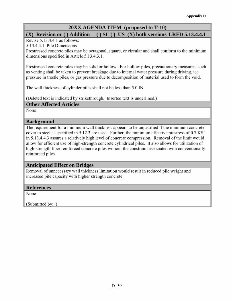
Appendix D
D–59
20XX AGENDA ITEM (proposed to T-10)
(X) Revision or ( ) Addition ( ) SI ( ) US (X) both versions LRFD 5.13.4.4.1 Revise 5.13.4.4.1 as follows: 5.13.4.4.1 Pile Dimensions Prestressed concrete piles may be octagonal, square, or circular and shall conform to the minimum dimensions specified in Article 5.13.4.3.1. Prestressed concrete piles may be solid or hollow. For hollow piles, precautionary measures, such as venting shall be taken to prevent breakage due to internal water pressure during driving, ice pressure in trestle piles, or gas pressure due to decomposition of material used to form the void. The wall thickness of cylinder piles shall not be less than 5.0 IN. (Deleted text is indicated by strikethrough. Inserted text is underlined.) Other Affected Articles None Background The requirement for a minimum wall thickness appears to be unjustified if the minimum concrete cover to steel as specified in 5.12.3 are used. Further, the minimum effective prestress of 0.7 KSI in 5.13.4.4.3 assures a relatively high level of concrete compression. Removal of the limit would allow for efficient use of high-strength concrete cylindrical piles. It also allows for utilization of high-strength fiber reinforced concrete piles without the constraint associated with conventionally reinforced piles. Anticipated Effect on Bridges Removal of unnecessary wall thickness limitation would result in reduced pile weight and increased pile capacity with higher strength concrete. References None (Submitted by: )


E–1
APPENDIX E—PROPOSED REVISIONS TO THE AASHTO LRFD BRIDGE CONSTRUCTION SPECIFICATIONS
TABLE OF CONTENTS
SECTION PAGE
8.2 Classes of Concrete............................................................................................................... E–3
8.3.1 Cements.............................................................................................................................. E–5
8.3.5 Combined Aggregates........................................................................................................ E–7
8.3.7 Mineral Admixtures ........................................................................................................... E–9
8.4.1 Responsibility and Criteria .............................................................................................. E–11
8.4.3 Cement Content ............................................................................................................... E–13
8.4.4 Mineral Admixtures ......................................................................................................... E–15
8.5.7.1 Tests .............................................................................................................................. E–17
8.5.7.3 For Acceptance of Concrete.......................................................................................... E–19
8.5.7.5 Steam and Radiant Heat-Cured Concrete ..................................................................... E–21
8.6.4.1 Protection During Cure ................................................................................................. E–23
8.6.6 and 8.6.7 Concrete Exposed to Salt Water and Concrete Exposed to Sulfate Soils or Water ........................................................................................................................... E–25
8.11.1 General........................................................................................................................... E–27
8.11.3.5 Steam or Radiant Heat Curing Method....................................................................... E–29
8.11.4 Bridge Decks.................................................................................................................. E–31
8.13.4 Curing ............................................................................................................................ E–33


Appendix E
E–3
PROPOSED CHANGE TO AASHTO LRFD Bridge Construction
Specifications (X) Revision or (X) Addition 8.2 Item No. 1 In 8.2.2 Normal-Density Concrete, revise the first paragraph and add two new classes of high performance concrete to Table 8.2.2-1: 8.2.2 Normal-Density Concrete Eight Ten classes of normal-density concrete are provided for in these specifications as listed in Table 8.2.2-1, except that for concrete on or over saltwater or exposed to deicing chemicals, the maximum water/cementitious materials ratio shall be 0.45.
Min. Cement Content
Max. Water/ Cementitious
Materials RatioAir Content
Range
Size of Coarse Aggregate Per AASHTO M 43
(ASTM D 448) Size
Number
Specified Compressive
Strength (28 Days)
Class of Concrete
kg/m3 kg per kg % Nominal Size
Square Openings MPa
P(HPC) —a 0.40 As specified
in the contract
≤ 19 mm 67 > 41 as
specified in the contract
A(HPC) —a 0.45 As specified
in the contract
—a —a 28
a Minimum cementitious materials content and coarse aggregate size to be selected to meet other performance criteria specified in the contract. Item No. 2 Add a commentary as follows: C8.2.2 Class P(HPC) concrete is used for prestressed concrete when strengths in excess of 41 MPa are specified and should always be used for specified concrete strengths greater than 69 MPa. Class A(HPC) concrete is used for cast-in-place substructures and superstructures when low permeability or other performance characteristics are specified. (Deleted text is indicated by strikethrough. Inserted text is underlined.) Other Affected Articles 8.4.3 and AASHTO LRFD Bridge Design Specifications Table C5.4.2.1-1

Appendix E
E–4
Background With high performance concrete, it is desirable that the specifications be performance based. The introduction of two new classes of concrete is a move in this direction. Class P(HPC) is intended for use in prestressed concrete members with a specified concrete compressive strength greater than 41 MPa (6000 psi). Class A (HPC) is intended for use in cast-in-place construction where performance criteria in addition to concrete compressive strengths are specified. Other criteria might include shrinkage, chloride permeability, freeze-thaw resistance, deicer scaling resistance, abrasion resistance, or heat of hydration.(1,2) The proposed change to the heading of the third column will affect all classes of concrete listed in the existing table and makes the table more consistent with the state-of-the-art of concrete technology. Square Openings has been changed to Nominal Size because the listed quantities are aggregate sizes. For both classes of concrete, a minimum cement content is not included since this should be selected by the producer based on the specified performance criteria. Maximum water-cementitious materials ratios have been included. The value of 0.40 for Class P(HPC) is less than the value of 0.49 for Class P whereas the value of 0.45 for Class A(HPC) is the same as that for Class A(AE). For Class P(HPC) concrete, a maximum size of coarse aggregate is specified since it is difficult to achieve the higher concrete compressive strengths with aggregates larger than 19 mm (3/4 in). For Class A(HPC) concrete, the maximum aggregate size should be selected by the producer based on the specified performance criteria. Anticipated Effect on Bridges Encourage the use of high performance concrete with higher strength, lower permeability, or other performance criteria. References 1. Goodspeed, C. H., Vanikar, S., and Cook, R., "High Performance Concrete Defined for Highway Structures," Concrete International, Vol. 18, No. 2, February 1996, pp. 62-67. 2. High Performance Concrete, Compact Disc, Federal Highway Administration, Version 3.0, February 2003. (Submitted by: )

Appendix E
E–5
PROPOSED CHANGE TO AASHTO LRFD Bridge Construction
Specifications (X) Revision or (X) Addition 8.3.1 Item No. 1 Revise 8.3.1 Cements as follows: 8.3.1 Cements Portland cements shall conform to the requirements of AASHTO M 85 (ASTM C 150) and blended hydraulic cements shall conform to the requirements of AASHTO M 240 (ASTM C 595M) or ASTM C 1157. For Type IP portland–pozzolan cement, the pozzolan constituent shall not exceed 20 percent of the mass of the blend and the loss on ignition of the pozzolan shall not exceed 5 percent.
Except for Class P(HPC) and Class A(HPC) or when Unless otherwise specified in the contract documents, only Type I, II, or III portland cement, Types IA, IIA, IIIA air entrained portland cement or Types IP or IS blended hydraulic cements shall be used. Types IA, IIA, and IIIA cements may be used only in concrete where air entrainment is required.
Low-alkali cements conforming to the requirements of AASHTO M 85 (ASTM C 150) for low-alkali cement shall be used when specified in the contract documents or when ordered by the Engineer as a condition of use for aggregates of limited alkali-silica reactivity.
Unless otherwise permitted, the product of only one mill of any one brand and type of cement shall be used for like elements of a structure that are exposed to view, except when cements must be blended for reduction of any excessive air-entrainment where air entraining cement is used.
For Class P(HPC) and Class A(HPC), trial batches using all intended constituent materials shall be made prior to concrete placement to ensure that cement and admixtures are compatible. Changes in the mill, brand, or type of cement shall not be permitted without additional trial batches.
Item No. 2 Add a commentary as follows: C8.3.1 ASTM C 1157 is a performance specification that does not require restrictions on the composition of the cement or its constituents. It can be used to accept cements not conforming to AASHTO M 85 (ASTM C 150) and AASHTO M 240 (ASTM C 595M). The low alkali requirement of AASHTO M 85 (ASTM C 150) does not provide protection against alkali-silica reactivity in all cases. A better approach is provided in AASHTO M 6 and M 80. (Deleted text is indicated by strikethrough. Inserted text is underlined.) Other Affected Articles AASHTO M 6 and M 80 with proposed Supplementary Requirement Background ASTM C 1157 is a standard performance specification for blended cements and should be included.(1) Restricting the cements to Types I, II, III, IA, IIA, IIIA, IP, or IS may prevent innovation and selection to enhance the performance of HPC.

Appendix E
E–6
Interactions between cementitious materials and chemical admixtures can cause incompatibility leading to premature stiffening, extended setting time, or inadequate air-void system. HPC may be very sensitive to the brand, type, and mill of origin of the cement. Studies have shown that changing the brand of cement can cause large differences in the hardened properties of HPC.(2)
Anticipated Effect on Bridges More choices, improved properties, and less problems in the field. References 1. ASTM C 1157 Standard Performance Specification for Blended Hydraulic Cement. 2. ACI 363 Committee, "State-of-the-Art Report on High-Strength Concrete (ACI 363R-92)," American Concrete Institute, Farmington Hills, MI, 1992, 55 pp. (Submitted by: )

Appendix E
E–7
PROPOSED CHANGE TO AASHTO LRFD Bridge Construction
Specifications ( ) Revision or (X) Addition 8.3.5 Item No. 1 Add a new article 8.3.5 and renumber subsequent articles. 8.3.5 Combined Aggregates Blends of fine and coarse aggregates shall conform to the requirements of AASHTO M XX1 Item No. 2 Add a commentary as follows: C8.3.5 The use of a combined aggregate grading can result in the use of less water, cementitious materials, and paste, and lead to improved fresh and hardened concrete properties. (Deleted text is indicated by strikethrough. Inserted text is underlined.) Other Affected Articles Material specifications M 6, M 43, and M 80 Background A new specification on combined aggregates has been proposed and needs to be referenced. Combined aggregates enable the use of less water, cementitious materials, and paste leading to improved properties in the freshly mixed and hardened concrete. Anticipated Effect on Bridges Improved concrete properties. References None (Submitted by: )


Appendix E
E–9
PROPOSED CHANGE TO AASHTO LRFD Bridge Construction
Specifications (X) Revision or ( ) Addition 8.3.7 Item No. 1 Replace the first paragraph of 8.3.7 Mineral Admixtures as follows: 8.3.7 Mineral Admixtures Fly ash pozzolans and calcined natural pozzolans for use as mineral admixtures in concrete shall conform to the requirements of AASHTO M 295 (ASTM C 618). Mineral admixtures in concrete shall conform to the following requirements: Fly ash pozzolans and calcined natural pozzolans – AASHTO M 295 (ASTM C 618) Ground granulated blast-furnace slag – AASHTO M 302 (ASTM C 989) Silica fume – AASHTO M 307 (ASTM C 1240) Item No. 2 Add a commentary as follows: C8.3.7 Pozzolans (fly ash, silica fume) and slag are used in the production of Class P(HPC) and Class A(HPC) concretes especially to extend the service life. (Deleted text is indicated by strikethrough. Inserted text is underlined.) Other Affected Articles 8.4.4 Background Slag and silica fume are widely used in HPC and need to be referenced. Anticipated Effect on Bridges More choices of materials. References None (Submitted by: )


Appendix E
E–11
PROPOSED CHANGE TO AASHTO LRFD Bridge Construction
Specifications (X) Revision or ( ) Addition 8.4.1 Item No. 1 Revise 8.4.1.1 Responsibility and Criteria as follows: 8.4.1.1 Responsibility and Criteria The contractor shall design and be responsible for the performance of all concrete mixes used in structures. The mix proportions selected shall produce concrete that is sufficiently workable and finishable for all uses intended and shall conform to the requirements in Table 8.2.2-1 and all other requirements of this Section. For normal-density concrete, the absolute volume method, such as described in American Concrete Institute Publication 211.1, shall be used in selecting mix proportions. For Class P(HPC) with fly ash, the method given in American Concrete Institute Guide 211.4 shall be permitted. For low-density concrete, the mix proportions shall be selected on the basis of trial mixes, with the cement factor rather than the water/cement ratio being determined by the specified strength, using methods such as those described in American Concrete Institute Publication 211.2. The mix design shall be based on the specified properties. When strength is specified, select upon obtaining an average concrete strength sufficiently above the specified strength so that, considering the expected variability of the concrete and test procedures, no more than one in ten strength tests will be expected to fall below the specified strength. Mix designs shall be modified during the course of the work when necessary to ensure compliance with strength and consistency requirements the specified fresh and hardened concrete properties. For Class P(HPC) and Class A(HPC), such modifications shall only be permitted after trial batches to demonstrate that the modified mix design will result in concrete that complies with the specified concrete properties. Item No. 2 Add a commentary as follows: C8.4.1.1 For Class P(HPC) with fly ash, the method given in ACI Guide 211.4 is permitted. In Class P(HPC) and Class A(HPC) concretes, properties other than compressive strength are also important, and the mix design should be based on specified properties rather than only compressive strength. Item No. 3 Revise 8.4.1.2 Trial Batch Tests as follows: 8.4.1.2 Trial Batch Tests For classes A, A(AE), and P, P(HPC), and A(HPC) concrete, for low-density concrete, and for other classes of concrete when specified in the contract documents or ordered by the Engineer, satisfactory performance of the proposed mix design shall be verified by laboratory tests on trial batches. The results of such tests shall be furnished to the Engineer by the Contractor or the Manufacturer of the precast elements at the time the proposed mix design is submitted. For mix design approval, the strengths of a minimum of five test cylinders taken from a trial batch shall average at least 5.6 MPa greater than the specified strength. If materials and a mix design identical to those proposed for use have been used on other work

Appendix E
E–12
within the previous year, certified copies of concrete test results from this work that indicate full compliance with these specifications may be substituted for such laboratory tests. If the results of more than 10 such strength tests are available from historical records for the past year, average strength for these tests shall be at least 1.28 standard deviations above the specified strength. The average values obtained from trial batches for the specified properties, such as strength shall exceed design values by a certain amount based on variability. For compressive strength, the required average strength used as a basis for selection of concrete proportions shall be determined in accordance with AASHTO M 241. Item No. 4 Add a commentary as follows: C8.4.1.2 In Class P(HPC) and Class A(HPC) concretes, properties other than compressive strength are also important. However, if only compressive strength is specified, AASHTO M 241 provides the method to determine the required average strength. (Deleted text is indicated by strikethrough. Inserted text is underlined.) Other Affected Articles AASHTO M 241 Background Item Nos. 1 and 2 ACI Guide 211.4 describes selecting proportions for high-strength concrete with portland cement and fly ash.(1) In HPC, type, size, and shape of aggregate become important.
Properties other than strength are also important in bridge structures.
Any modification to the mixture proportions and ingredients must be tested using trial batches.
Item Nos. 3 and 4 Properties other than strength are also included. Overstrength requirements are updated for all strength levels including high-strength concrete by referring to AASHTO M 241.(2,3) Revisions to AASHTO M 241 are also proposed. Anticipated Effect on Bridges More durable structures. Inclusion of high-strength concrete. References 1. ACI Committee 211, "Guide for Selecting Proportions for High-Strength Concrete with Portland Cement and Fly Ash (ACI 211.4)" American Concrete Institute, Farmington Hills, MI, 1993, 13 pp. 2. Cagley, J. R. "Changing from ACI 318-99 to ACI 318-02," Concrete International, American Concrete Institute, June 2001. 3. AASHTO M 241 Standard Specification for Concrete Made by Volumetric Batching and Continuous Mixing. (Submitted by: )

Appendix E
E–13
PROPOSED CHANGE TO AASHTO LRFD Bridge Construction
Specifications ( ) Revision or (X) Addition 8.4.3 Item No. 1 Revise 8.4.3 Cement Content as follows: The minimum cement content shall be as listed in Table 8.2.1-1 or otherwise specified in the contract documents. For Class P(HPC), the total cementitious materials content shall be specified not to exceed 593 kg/m3 of concrete. For other classes of concrete, Tthe maximum cement or cement plus mineral admixture content shall not exceed 475 363 kg/m3 of concrete. The actual cement content used shall be within these limits and shall be sufficient to produce concrete of the required strength, and consistency, and performance. Item No. 2 Add a commentary as follows: C8.4.3 Many high-strength concretes require a cementitious materials content greater than the traditional AASHTO limit of 475 kg/m3. However, when cementitious materials contents in excess of 593 kg/m3 are required in high-strength concrete, optimization of other constituent materials or alternative constituent materials should be considered. (Deleted text is indicated by strikethrough. Inserted text is underlined.) Other Affected Articles 8.2 Background The current maximum cement content of 363 kg/m3 (611 lb/yd3) appears to be an error since table 8.2.2-1 lists minimum cement contents as high as 390 kg/m3 (657 lb/yd3). It is also inconsistent with 475 kg/m3 (800 lb/yd3) specified in the LRFD Bridge Design Specifications, 5.4.2.1. Many high-strength concretes require a cementitious materials content in excess of 475 kg/m3 (800 lb/yd3).(1) A higher limit is, therefore, appropriate. Anticipated Effect on Bridges Facilitate the use of high-strength and high performance concrete. References 1. High Performance Concrete, Compact Disc, Federal Highway Administration, Version 3.0, February 2003. (Submitted by: )


Appendix E
E–15
PROPOSED CHANGE TO AASHTO LRFD Bridge Construction
Specifications (X) Revision or ( ) Addition 8.4.4 Item No. 1 Revise 8.4.4 Mineral Admixtures as follows: 8.4.4 Mineral Admixtures Mineral admixtures shall be used in the amounts specified in the contract documents. In addition,For all classes of concrete except P(HPC) and A(HPC), when either Types I, II, IV, or V AASHTO M 85 (ASTM C 150) cements are used and mineral admixtures are neither specified in the contract documents nor prohibited, the Contractor will be permitted to replace up to 20 25 percent of the required portland cement with a mineral admixture fly ash or other pozzolan conforming to AASHTO M 295, up to 50 percent of the required portland cement with slag conforming to AASHTO M 302, or up to 10 percent of the required portland cement with silica fume conforming to AASHTO M 307. When any combination of fly ash, slag, and silica fume are used, the Contractor will be permitted to replace up to 50 percent of the required portland cement. However, no more than 25 percent shall be fly ash and no more than 10 percent shall be silica fume. The mass of the mineral admixture used shall be equal to or greater than the mass of the portland cement replaced. In calculating the water/-cementitious materials ratio of the mix, the mass of the cementitious materials shall be considered to be the sum of the mass of the portland cement and the mineral admixtures. For Class P(HPC) and Class A(HPC) concrete, mineral admixtures (pozzolans or slag) shall be permitted to be used as cementitious materials with portland cement in blended cements or as a separate addition at the mixer. The amount of mineral admixture shall be determined by trial batches. The water-cementitious materials ratio shall be the ratio of the mass of water to the total cementitious materials, including the mineral admixtures. The properties of the freshly mixed and hardened concrete shall comply with specified values. Item No. 2 Add a commentary as follows: C8.4.4 Mineral admixtures are widely used in concrete in the percentages given. For Class P(HPC) and Class A(HPC) concretes, different percentages may be used if trial batches substantiate that such amounts provide the specified properties. (Deleted text is indicated by strikethrough. Inserted text is underlined.) Other Affected Articles 8.3.7 Background Mineral admixtures are widely used in HPC today. These include fly ash, ground granulated blast-furnace slag, and silica fume. The use of these materials results in a concrete with a finer pore structure and, therefore, lower permeability. The proposed replacement percentages are based on those in ACI 318 for concrete exposed to deicing chemicals.(1) Trial batches are required with HPC to ensure that the specified properties are achieved.

Appendix E
E–16
Anticipated Effect on Bridges Improved concrete for more durable structures. References 1. ACI Committee 318, Building Code Requirements for Structural Concrete (318-02) and Commentary (318R-02), American Concrete Institute, Farmington Hills, MI, 2002, 443 pp. (Submitted by: )

Appendix E
E–17
PROPOSED CHANGE TO AASHTO LRFD Bridge Construction
Specifications (X) Revision or ( ) Addition 8.5.7.1 Item No. 1 Revise 8.5.7.1 Tests as follows: 8.5.7.1 Tests A strength test shall consist of the average strength of at least two 150x300-mm or at least three 100x200-mm compressive strength test cylinders fabricated from material taken from a single randomly selected batch of concrete, except that, if any cylinder should show evidence of improper sampling, molding, or testing, said cylinder shall be discarded and the strength test shall consist of the strength of the remaining cylinder(s). A minimum of three cylinders shall be fabricated for each strength test when the specified strength exceeds 34 MPa. Item No. 2 Add a commentary as follows: The use of 100x200-mm cylinders for measuring concrete compressive strengths is increasing. Test results using the smaller size cylinder have a higher variability compared to 150x300 mm cylinders. This can be offset by requiring three cylinders of the smaller size compared to two for the larger size. Since measurement of compressive strength is more critical for high-strength concrete, three cylinders are required for both cylinder sizes. (Deleted text is indicated by strikethrough. Inserted text is underlined.) Other Affected Articles AASHTO M 241 Background 100x200-mm cylinders are commonly used for testing high-strength concrete and may exhibit higher variability.(1) For high-strength concrete, strength is more critical, and at least three cylinders are recommended for any size.(2) Anticipated Effect on Bridges Improved quality of concrete and more valid measurements of compressive strength. References 1. Ozyildirim, C., "4 x 8 inch Concrete Cylinders versus 6 x 12 inch Cylinders," VHTRC 84-R44, Virginia Transportation Research Council, Charlottesville, VA, May 1984, 25 pp. 2. ACI Committee 363, "Guide to Quality Control and Testing of High-Strength Concrete (ACI 363.2R-98)," American Concrete Institute, Farmington Hills, MI, 1998, 18 pp. (Submitted by: )


Appendix E
E–19
PROPOSED CHANGE TO AASHTO LRFD Bridge Construction
Specifications (X) Revision or ( ) Addition 8.5.7.3 Item No. 1 Revise 8.5.7.3 For Acceptance of Concrete as follows: 8.5.7.3 For Acceptance of Concrete For determining compliance of concrete with a specified 28-day strength, test cylinders shall be cured under controlled conditions as described in AASHTO T 23 (ASTM C 31), Article 9.3, and tested at the specified age of 28 days. Samples for acceptance tests for each class of concrete shall be taken not less than once a day nor less than once for each 100 m3 of concrete or once for each major placement. Except for Class P(HPC) and Class A(HPC) concrete, aAny concrete represented by a test that indicates a strength that is less than the specified 28-day compressive strength at the specified age by more than 3.5 MPa will be rejected and shall be removed and replaced with acceptable concrete. Such rejection shall prevail unless either: • The Contractor, at the Contractor's expense, obtains and submits evidence of a type
acceptable to the Engineer that the strength and quality of the rejected concrete is acceptable. If such evidence consists of cores taken from the work, the cores shall be obtained and tested in accordance with the standard methods of AASHTO T 24 (ASTM C 42), or
• The Engineer determines that said concrete is located where it will not create an intolerable
detrimental effect on the structure and the Contractor agrees to a reduced payment to compensate the Owner for loss of durability and other lost benefits.
For Class P(HPC) and Class A(HPC) concrete, any concrete represented by a test that indicates a strength that is less than the specified compressive strength at the specified age will be rejected and shall be removed and replaced with acceptable concrete. Item No. 2 Add a commentary as follows: C8.5.7.3 The concrete age when the specified strength is to be achieved must be shown on the project drawings. (Deleted text is indicated by strikethrough. Inserted text is underlined.) Other Affected Articles None Background Test ages other than 28 days are frequently specified for high-strength concrete.(1) The elimination of 28 days in this provision allows the use of other test ages. A goal of HPC is to provide concrete that meets the specification for the intended application. Accepting concrete that does not meet the specified compressive strength is not an acceptable

Appendix E
E–20
practice for HPC. A reduced payment cannot compensate for a loss of durability and possible reduced service life. Anticipated Effect on Bridges Improved quality of concrete. References 1. High Performance Concrete, Compact Disc, Federal Highway Administration, Version 3.0, February 2003. (Submitted by: )

Appendix E
E–21
PROPOSED CHANGE TO AASHTO LRFD Bridge Construction
Specifications ( ) Revision or (X) Addition 8.5.7.5 Item No. 1 Revise 8.5.7.5 Steam and Radiant Heat-Cured Concrete as follows: 8.5.7.5 Precast Concrete Cured by the Waterproof Cover Method, Steam and or Radiant Heat Heat-Cured Concrete When a precast concrete member is cured by the waterproof cover method, steam, or radiant heat-cured, the compressive strength test cylinders made for any of the above purposes shall be cured under conditions similar to the member. Such concrete shall be considered to be acceptable whenever a test indicates that the concrete has reached the specified 28-day compressive strength provided such strength is reached not more than 28 days after the member is cast no later than the specified age for the compressive strength. Test cylinders shall be cured by only one of the following methods: (1) For concrete with specified design compressive strengths less than or equal to 41 MPa, test cylinders shall be stored next to the member and under the same covers such that the cylinders are exposed to the same temperature conditions as the member. (2) For all specified concrete strengths, test cylinders shall be match-cured in chambers in which the temperature of the chamber is correlated with the temperature in the member prior to release of the prestressing strands. Temperatures of the chamber and member shall be verified by use of temperature sensors in the chamber and member. Unless specified otherwise, temperature sensors in I-beams shall be located at the center of gravity of the bottom flange. For other members, the temperature sensors shall be located at the center of the thickest section. The location shall be specified on the drawings. After release of the prestressing strands, cylinders shall be stored in a similar temperature and humidity environment as the member. Item No. 2 Add a commentary as follows: C8.5.7.5 For specified concrete compressive strengths greater than 41 MPa, test cylinders should be match cured in chambers in which the temperature of the chamber is correlated with the temperature in the member prior to release of the prestressing strands. Temperature sensors for the match curing system should be placed at the most critical locations for strength development at release of the prestressing force and for design. The Engineer should determine the critical locations for temperature sensors in each type of member and show the locations on the drawings. After release of the prestressing strands, cylinders should be stored in a similar temperature and humidity environment as the member. (Deleted text is indicated by strikethrough. Inserted text is underlined.) Other Affected Articles None

Appendix E
E–22
Background Research on several FHWA-State high performance concrete showcase projects has shown that the strength of quality control cylinders is affected by the curing temperatures that the cylinders experience.(1,2) A high initial curing temperature accelerates the strength gain at early ages but results in a slower strength gain at later ages. Consequently, a test cylinder that experiences a different temperature history from the member that it represents does not truly represent the strength of the concrete in the member either at an age corresponding to release of the strands or at later ages. This effect becomes more significant with high-strength concrete because of the higher cementitious materials content and higher heat of hydration. Placing the test cylinders under the same covers as the member has proved to be an acceptable method for conventional strength concretes. However, for high-strength concretes, match curing is essential if realistic values of strength are to be measured.(3) The proposed changes allow the traditional method to be used for conventional strength concretes while requiring match curing for high-strength concretes and allowing match curing for conventional strength concretes. Anticipated Effect on Bridges Provides a more realistic measure of the compressive strength of concrete in the member. References 1. High Performance Concrete, Compact Disc, Federal Highway Administration, Version 3.0, February 2003. 2. Meyers, J. J. and Carrasquillo R. L., "Production and Quality Control of High Performance Concrete in Texas Bridge Structures," Center for Transportation Research, The University of Texas at Austin, Research Report 580/589-1, 2000, 553 pp. 3. Russell, H. G., "Consider Match Curing for High-Strength Precast," Concrete Products, Vol. 102, No. 7, July 1999, pp. 117-118. (Submitted by: )

Appendix E
E–23
PROPOSED CHANGE TO AASHTO LRFD Bridge Construction
Specifications (X) Revision or ( ) Addition 8.6.4.1 Item No. 1 Revise 8.6.4.1 Protection During Cure as follows: 8.6.4.1 Protection During Cure When there is a probability of air temperatures below 2oC during the cure period, the Contractor shall submit for approval by the Engineer prior to concrete placement a cold weather concreting and curing plan detailing the methods and equipment which will be used to ensure that the required concrete temperatures are maintained. The concrete shall be maintained at a temperature of not less than 7oC for the first 6 days after placement, except that when pozzolans or slag are cement or fly ash cement is used, this period shall be as shown in Table 8.6.4.1-1:
Table 8.6.4.1-1 Pozzolan Cement and Temperature Control Period
Percentage of Cement Replaced, by Mass, with
Pozzolans Slag
Required Period of Controlled Temperature
10% 25% 8 Days
11-15% 26-35% 9 Days
16-20% 36-50% 10 Days The requirement in Table 8.6.4.1-1 for an extended period of controlled temperature may be waived if a compressive strength of 65 percent of the specified 28-day design strength is achieved in 6 days using site-cured cylinders or the match-curing system or the maturity method. When the percentage of cement replacement is larger than the values listed above or when combinations of materials are used as cement replacement, the required period of controlled temperature shall be at least 6 days and shall continue until a compressive strength of 65 percent of the specified design strength is achieved using site-cured cylinders or the match-curing system or the maturity method. If external heating is employed, the heat shall be applied and withdrawn gradually and uniformly so that no part of the concrete surface is heated to more than 32oC or caused to change temperature by more than 11oC in 8 hours. When requested by the Engineer, the Contractor shall provide and install two maximum-minimum type thermometers at each structure site. Such thermometers shall be installed as directed by the Engineer so as to monitor the temperature of the concrete and the surrounding air during the cure period. Item No. 2 Add a commentary as follows: C8.6.4.1 Addition of pozzolans or slag may result in slower development of properties. Therefore, longer curing periods may be needed. Thermal heating and cooling rates are limited to minimize the

Appendix E
E–24
thermal strains. (Deleted text is indicated by strikethrough. Inserted text is underlined.) Other Affected Articles None Background The current provision only addresses pozzolans up to a cement replacement of 20 percent and needs to be more general. Instead of fixed periods of controlled temperature, the match-curing system or maturity method should be allowed. Both methods can be effective with HPC. Anticipated Effect on Bridges The changes allow for a wider range of cement replacements and optional methods to reduce the required period of controlled temperature. The latter will allow for faster bridge construction. References None (Submitted by: )

Appendix E
E–25
PROPOSED CHANGE TO AASHTO LRFD Bridge Construction
Specifications (X) Revision or ( ) Addition 8.6.6 and 8.6.7 Item No. 1 Revise 8.6.6 Concrete Exposed to Saltwater as follows: 8.6.6 Concrete Exposed to Saltwater Unless otherwise specified in the contract documents, concrete for structures exposed to salt or brackish water shall comply with the requirements of Class A(HPC) concrete. be Class S for concrete placed under water and Class A for other work. Such concrete shall be mixed for a period of not less than 2 minutes and the water content of the mixture shall be carefully controlled and regulated so as to produce concrete of maximum impermeability. The concrete shall be thoroughly consolidated as necessary to produce maximum density and a complete lack of rock pockets. Unless otherwise indicated in the contract documents, the clear distance from the face of the concrete to the reinforcing steel shall be not less than 100 mm. No construction joints shall be formed between levels of extreme low water and extreme high water or the upper limit of wave action as determined by the Engineer. Between these levels the forms shall not be removed, or other means provided, to prevent saltwater from coming in direct contact with the concrete for a period of not less than 30 days after placement. Except for the repair of any rock pockets and the plugging of form ties holes, the original surface as the concrete comes from the forms shall be left undisturbed. Special handling shall be provided for precast members to avoid even slight deformation cracks. Item No. 2 Add a Commentary as follows: C8.6.6 Penetration of harmful solutions accelerates the deterioration of concrete. The most widely experienced environmental distress is the corrosion of the reinforcing steel. Chloride solutions destroy the protective coating around the reinforcing steel initiating and accelerating the corrosion of the steel. Concrete should be prepared using the proper ingredients and proportions and cured for a period of time before exposure to the severe environment such that the penetration of the harmful solutions is minimized. Item No. 3 Revise 8.6.7 Concrete Exposed to Sulfate Soils or Water as follows: 8.6.7 Concrete Exposed to Sulfate Soils or Sulfate Water When the contract documents identify the area as containing sulfate soils or sulfate water, the concrete that will be in contact with such soil or water shall be Class A(HPC) and shall be mixed, placed, and protected from contact with soil or water as required for concrete exposed to saltwater except that the protection period shall be not less than 72 hours. Item No 4 Add a Commentary as follows: C8.6.7 Sulfate soils or water may contain high levels of sulfates of sodium, potassium, calcium, or magnesia. Penetration of sulfate solutions into concrete may result in chemical reactions that cause disintegration of concrete. Therefore, special precautions may be needed to minimize the intrusion of harmful sulfate solutions. Avoidance of construction joints that may facilitate the intrusion of sulfate solutions, proper material selection and proportioning, production of low permeability

Appendix E
E–26
concrete, and avoidance of cracking through proper curing are needed. (Deleted text is indicated by strikethrough. Inserted text is underlined.) Other Affected Articles None Background HPC with low permeability are essential to provide the needed protection for concrete exposed to salt or sulfate solutions.(1) Class A(HPC) is intended for these applications. Anticipated Effect on Bridges Provide a lower permeability concrete. References 1. ACI Committee 222, "Corrosion of Metals in Concrete (ACI 222R-96)," American Concrete Institute, Farmington Hills, MI, 1996, 30 pp. (Submitted by: )

Appendix E
E–27
PROPOSED CHANGE TO AASHTO LRFD Bridge Construction
Specifications (X) Revision or ( ) Addition 8.11.1 Revise 8.11.1 General as follows: All newly placed concrete shall be cured so as to prevent the loss of water by use of one or more of the methods specified herein. Except for Class A(HPC) concrete, Ccuring shall commence immediately after the free water has left the surface and finishing operations are completed. For Class A(HPC) concrete, water curing shall commence immediately after finishing operations are complete. If the surface of the concrete begins to dry before the selected cure method can be applied, the surface of the concrete shall be kept moist by a fog spray applied so as not to damage the surface. Curing by other than waterproof cover method with precast concrete or steam or radiant heat methods shall continue uninterrupted for seven days except that when pozzolans in excess of 10 percent, by mass, of the portland cement are used in the mix. When such pozzolans are used, the curing period shall be 10 days. For other than top slabs of structures serving as finished pavements, and Class A(HPC) concrete, the above curing periods may be reduced and curing terminated when test cylinders cured under the same conditions as the structure indicate that concrete strengths of at least 70 percent of that specified have been reached. When deemed necessary by the Engineer during periods of hot weather, water shall be applied to concrete surfaces being cured by the liquid membrane method or by the forms-in-place method, until the Engineer determines that a cooling effect is no longer required. Such application of water will be paid for as extra work. (Deleted text is indicated by strikethrough. Inserted text is underlined.) Other Affected Articles 8.11.4 and 8.13.4 Background Changes to 8.11.1 are needed to make it consistent with changes to 8.11.4 and 8.13.4.(1,2,3)
Anticipated Effect on Bridges Improved quality and durability of bridge decks. References 1. High Performance Concrete, Compact Disc, Federal Highway Administration, Version 3.0, February 2003. 2. Meyers, J. J. and Carrasquillo R. L., "Production and Quality Control of High Performance Concrete in Texas Bridge Structures," Center for Transportation Research, The University of Texas at Austin, Research Report 580/589-1, 2000, 553 pp. 3. HPC Bridge Views, Issue No. 15, May/June 2001. (Submitted by: )


Appendix E
E–29
PROPOSED CHANGE TO AASHTO LRFD Bridge Construction
Specifications (X) Revision or (X) Addition 8.11.3.5 Revise 8.11.3.5 Steam or Radiant Heat Curing Method as follows: Item No. 1 Add the following at the end of the second paragraph: Steam curing or radiant heat curing shall be done under a suitable enclosure to contain the live steam or the heat. Steam shall be low pressure and saturated. Temperature recording devices shall be employed as necessary to verify that temperatures are uniform throughout the enclosure concrete and within the limits specified in the contract documents. Item No. 2 Revise the third paragraph as follows: The initial application of the steam or of the heat shall be from 2 to 4 hours after the final placement of concrete to allow the initial set of the concrete to take place. If retarders are used, the waiting period before application of the steam or of the radiant heat shall be increased to between 4 and 6 hours after placement. not occur prior to initial set of the concrete except to maintain the temperature within the curing chamber above the specified minimum temperature. The time of initial set may be determined by the Standard Method of Test for "Time of Setting of Concrete Mixtures by Penetration Resistance," AASHTO T 197 (ASTM C 403)., and the time limits described above may then be waived. Item No. 3 Revise the fifth paragraph as follows: Application of live steam shall not be directed on the concrete or on the forms so as to cause localized high temperatures. During the initial application of live steam or of radiant heat, the ambient temperature within the curing enclosure concrete shall increase at an average rate not exceeding 22oC per hour until the curing temperature is reached. The maximum curing temperature within the enclosure concrete shall not exceed 71oC. The maximum temperature shall be held until the concrete has reached the desired strength. In discontinuing the steam application, the ambient air concrete temperature shall not decrease at a rate to exceed 22oC per hour until a temperature 11oC above the temperature of the air to which the concrete will be exposed has been reached. Item No. 4 Revise the last paragraph as follows: Unless the ambient temperature is maintained above 16oC, for prestressed members the transfer of the stressing force to the concrete shall be accomplished immediately after the steam curing or the heat curing has been discontinued. For prestressed members, the transfer of the stressing force to the concrete shall be accomplished immediately after the steam curing or heat curing has been discontinued. Item No. 5 Add a commentary as follows: C8.11.3.5 Since high-strength concrete generates more heat of hydration than conventional strength concretes, it is important that concrete temperatures be monitored rather than enclosure temperatures. It is also important that transfer of prestressing force to the concrete occur before the

Appendix E
E–30
temperature of the concrete decreases. Otherwise, vertical cracking in the girders may result. (Deleted text is indicated by strikethrough. Inserted text is underlined.) Other Affected Articles 8.2 Background Item No. 1 Since high-strength concrete generates significantly more heat than conventional strength concrete, it is important that concrete temperatures be monitored rather than temperatures throughout the enclosure.(1) Item No. 2 Since today's concretes may contain a wider variety of constituent materials than in the past, the current criteria of 2 to 4 hours or 4 to 6 hours may not be appropriate.(1) Measurement of time of set for the specific concrete is a more precise approach. Item No. 3 Research has shown that delayed ettringite formation (DEF) can occur in concretes subjected to high temperatures during curing and subsequently exposed to moisture. A maximum temperature of about 71 oC (160 oF) is generally recognized as an upper limit below which DEF is unlikely to occur. The PCI Quality Control Manual contains a recommendation that maximum concrete temperature should be limited to 70 oC (158 oF) if a known potential for alkali-silica reaction or DEF exists. Otherwise, the maximum concrete temperature is 82 oC (180 oF).(2) Item No. 4 The current provision allows the ambient temperature to fall as low as 16 oC (60 oF) before the strands are released. A large decrease in concrete and strand temperatures prior to release of the strands can result in vertical cracks in the member. This is more likely in deep members and high-strength concrete members. Immediate release of the strands after the steam or heat curing minimizes the likelihood of cracking.(3) Anticipated Effect on Bridges Improved quality of concrete in prestressed concrete girders and less cracking in bridge girders prior to transfer of the prestressing force. References 1. High Performance Concrete, Compact Disc, Federal Highway Administration, Version 3.0, February 2003. 2. Manual for Quality Control for Plants and Production of Structural Precast Concrete Products, MNL-116-99, Precast/Prestressed Concrete Institute, Chicago, IL, 1999. 3. Zia, P. and Caner, A., "Cracking in Large-Sized Long Span Prestressed Concrete AASHTO Girders," Center for Transportation Engineering Studies, North Carolina State University, October 1993, 87 pp. (Submitted by: )

Appendix E
E–31
PROPOSED CHANGE TO AASHTO LRFD Bridge Construction
Specifications ( ) Revision or (X) Addition 8.11.4 Item No. 1 Add the following paragraph at the end of 8.11.4 Bridge Decks: When Class A(HPC) concrete is used in bridge decks, water cure shall be applied immediately after the finishing of any portion of the deck is complete and shall remain in place for a minimum period of seven days irrespective of concrete strength. If conditions prevent immediate application of the water cure, an evaporation retardant shall be applied immediately after completion of finishing or fogging shall be used to maintain a high relative humidity above the concrete to prevent drying of the concrete surface. Following the water cure period, liquid membrane curing compound may be applied to extend the curing period. Item No. 2 C8.11.4 High performance concrete tends to have very little bleed water, especially when a low water-cementitious materials ratio is used with mineral admixtures. As a result, the evaporation protection of the bleed water on the fresh concrete is lost. The most effective way to protect the concrete is by application of water cure as soon as screeding or tining of the concrete is complete and no later than 15 minutes after the concrete is placed in any portion of the deck. If this is not possible, the next best alternative is to prevent or reduce moisture loss from the concrete until the water cure can be applied. In the water cure method, the concrete surface is kept continuously wet. The most appropriate method is to cover the deck with materials such as cotton mats, multiple layers of burlap, or other materials that do not discolor or damage the concrete surface and to keep these materials continuously and thoroughly wet. The water cure needs to continue for a minimum of seven days irrespective of concrete strength. The use of a curing compound after the water cure extends the curing period while allowing the contractor to have access to the bridge deck. (Deleted text is indicated by strikethrough. Inserted text is underlined.) Other Affected Articles 8.11.1 Background See Item No. 2 and reference No. 1. Note that 8.11.1 requires 10 days curing when more than 10 percent pozzolans are used. Anticipated Effect on Bridges Improved quality and durability of bridge decks. References 1. HPC Bridge Views, Issue No. 15, May/June 2001. (Submitted by: )


Appendix E
E–33
PROPOSED CHANGE TO AASHTO LRFD Bridge Construction
Specifications (X) Revision or ( ) Addition 8.13.4 Item No. 1 Revise 8.13.4 Curing as follows: Unless otherwise permitted, precast members shall be cured by either the water method, waterproof cover method, or the steam or radiant heat method. The use of insulated blankets is permitted with the waterproof cover method. When the waterproof cover method is used, the air temperature beneath the cover shall not be less than 10oC and live steam or radiant heat may be used to maintain the temperature above the minimum value. The maximum concrete temperature during the curing cycle shall not exceed 71oC. The waterproof cover shall remain in place until such time as the compressive strength of the concrete reaches the strength specified for detensioning or stripping. Item No. 2 Add a commentary as follows: C8.13.4 Use of the waterproof cover method allows high-strength concretes to self cure without the addition of steam or radiant heat. The use of insulated blankets will depend on the external weather conditions. (Deleted text is indicated by strikethrough. Inserted text is underlined.) Other Affected Articles 8.11.1 Background High-strength concretes contain more cementitious material than used in conventional strength concrete.(1) Consequently, the heat generated during hydration is greater and sufficient heat can be generated to develop the compressive strength required for detensioning or stripping without the use of steam or radiant heating.(2) The new wording permits self-curing with or without insulated blankets by modifying the waterproof cover method. The revision also refers to concrete temperature rather than the enclosure temperature. Anticipated Effect on Bridges Reduce cost of girders since energy for heating is not required. References 1. High Performance Concrete, Compact Disc, Federal Highway Administration, Version 3.0, February 2003. 2. Meyers, J. J. and Carrasquillo R. L., "Production and Quality Control of High Performance Concrete in Texas Bridge Structures," Center for Transportation Research, The University of Texas at Austin, Research Report 580/589-1, 2000, 553 pp. (Submitted by: )


F–1
APPENDIX F—RESEARCH PROBLEM STATEMENTS
TABLE OF CONTENTS
SECTION PAGE F.1 MATERIALS RESEARCH 1. Performance Requirements for High-Performance Concrete ............................................... F–3
2. Use of Wash Water in High-Performance Concrete............................................................. F–7
3. Air-Void Requirements and Freeze-Thaw Testing Requirements for Durability of High-Performance Concrete ........................................................................................... F–11
4. Penetrability Criteria for High-Performance Concrete ....................................................... F–15
5. Curing of High-Performance Concrete............................................................................... F–19
6. Procedures for Measuring Compressive and Flexural Strengths of High-Strength Concrete .............................................................................................................................. F–23
F.2 STRUCTURAL RESEARCH
7. Application of Bridge Design Specifications to High-Strength Concrete Structural Members: Material Properties............................................................................................. F–27
8. Application of Bridge Design Specifications to High-Strength Concrete Structural Members: Shear Provisions Except Prestressed Concrete Beams...................................... F–31
9. Verification of Stress Limits and Resistance Factors for High-Performance Concrete .............................................................................................................................. F–35
10. Confinement of High-Strength Concrete Columns for Seismic and Nonseismic Regions ............................................................................................................................... F–39


Appendix F
F–3
I. PROBLEM NUMBER 1
II. PROBLEM TITLE Performance Requirements for High-Performance Concrete III. RESEARCH PROBLEM STATEMENT High-performance concrete (HPC) is expected to have performance characteristics exceeding those of conventional concretes. The desired characteristics may be related to mechanical properties (strength, elasticity, shrinkage, or creep) and to durability characteristics (resistance to freezing and thawing, scaling, abrasion, penetration of chlorides, sulfate attack, or alkali-silica reaction) or a combination of these.(1) An important performance criteria for bridge decks is the elimination of cracking. In specifications for admixtures, where the properties of concrete containing the admixture are compared with the properties of a similar reference concrete, the performance requirements for the concrete containing the admixture are less than 100 percent for strength or higher than 100 percent for shrinkage. For example, in AASHTO M 154, strengths of 90 percent and shrinkages of 120 percent of the reference concrete are allowed. In M 154 and M 194, the relative durability factor is 80. In table 1 of M 194, it is stated that the values include allowances for normal variation in test results. This was also mentioned in the paper by Newlon and Mitchell.(2) In HPC, tighter control and different values may be needed. In table 4 of AASHTO M 295 and M 307, the maximum difference in drying shrinkage of mortar bars at 28 days over the control mortar is given as 0.03 percent. In AASHTO M 302 for slag, there are no criteria for shrinkage. These values should be evaluated. Also, the applicability of the mortar test for concrete should be determined. This project should also evaluate if additional tests, such as sulfate resistance for fly ash concrete, are needed. The age at which standard tests are made should be considered since HPC properties may develop more slowly than for conventional concretes. The FHWA definition of HPC has adopted a test age of 56 days.(1) Each test method should encompass the materials used in HPC and have complete precision and bias statements. For example, AASHTO T 132 includes only portland cement in its statement; T 106 lists values for portland cements and blended cements; and T 97 does not have precision or bias values. AASHTO T 160 is used to measure the shrinkage of unrestrained concrete. However, no generally accepted test method is available to assess the cracking potential of concrete as used in

Appendix F
F–4
bridge decks. Development of a test will allow the development of a performance criteria related to cracking. IV. RESEARCH OBJECTIVE(S) The main objective of the proposed research is to develop performance criteria for HPC. For HPC, tighter control and improved performance requirements are needed. Precision and bias statements of test methods should be complete and include hydraulic cement concretes.
To accomplish the objective, the following tasks will be performed:
Task 1. Review performance criteria used in different AASHTO and ASTM specifications and test methods for HPC to identify where further research is needed. The review shall include the following standards as a minimum:
AASHTO M 154 (ASTM C 260)—Air-Entraining Admixtures for Concrete AASHTO M 194 (ASTM C 494)—Chemical Admixtures for Concrete AASHTO M 295 (ASTM C 618)—Coal Fly Ash and Raw Calcined Natural Pozzolans for Use as a Mineral Admixture in Concrete AASHTO M 302 (ASTM C 989)—Ground Granulated Blast-Furnace Slag for Use in Concrete and Mortars AASHTO M 307—Microsilica for Use in Concrete and Mortar AASHTO T 22 (ASTM C 39)—Compressive Strength of Cylindrical Concrete Specimens AASHTO T 97 (ASTM C 78)—Flexural Strength of Concrete (Using Simple Beam with Third-Point Loading) AASHTO T 106 (ASTM C 109)—Compressive Strength of Hydraulic Cement Mortar (Using 50-mm or 2-in. Cube Specimens) AASHTO T 126 (ASTM C 192)—Making and Curing Concrete Test Specimens in the Laboratory AASHTO T 132—Tensile Strength of Hydraulic Cement Mortars AASHTO T 160 (ASTM C 157)—Length Change of Hardened Hydraulic Cement Mortar and Concrete AASHTO T 161 (ASTM C 666)—Resistance of Concrete to Rapid Freezing and Thawing AASHTO T 178 (ASTM C 1084)—Cement Content of Hardened Portland Cement Concrete AASHTO T 259—Resistance of Concrete to Chloride Ion Penetration AASHTO T 276 (ASTM C 918)—Developing Early-Age Compression Test Values and Projecting Later-Age Strengths ASTM C 1012—Length Change of Hydraulic-Cement Mortars Exposed to a Sulfate Solution AASHTO Standard Specifications for Highway Bridges, Division II, 8.3.2 AASHTO LRFD Bridge Construction Specifications, 8.3.2

Appendix F
F–5
An initial review of these standards is available in the Final Report on FHWA Project No. DTFH61-00-C-00009 titled "Compilation and Evaluation of Results from High-Performance Concrete Bridge Projects."
Task 2. Develop a detailed work plan and test program to obtain the necessary data. Describe
how the work plan will provide the necessary data. It is anticipated that the following specimens will be included:
For compressive strength of concrete, use either the 150x300-mm or 100x200-mm (6x12-in or 4x8-in) specimens. Ends of specimens can be ground or capped with sulfur-mortar or tested with neoprene pads in extrusion rings. Three specimens should be used for a test result.
For resistance to freezing and thawing test, concrete specimen width or diameter shall range between 75 and 125 mm (3 and 5 in), and length between 280 and 405 mm (11 and 16 in). Use two beams or cylinders for a test result.
For length change in the sulfate test, concrete specimens shall have a minimum dimension of 75 mm (3 in) if the maximum size aggregate is 25 mm (1 in), and 100 mm (4 in) if the maximum size is 50 mm (2 in). Three specimens shall be prepared for each test condition. Statistical evaluation of the results shall be required to determine if the number of tests is sufficient to indicate a trend considering the variability of each test.
Task 3. Perform the work plan.
Task 4. Develop specific proposed revisions to AASHTO and ASTM specifications and test methods.
Task 5. Submit a final report documenting the entire work effort including recommended revisions to the specifications and test methods.
V. ESTIMATE OF PROBLEM FUNDING AND RESEARCH PERIOD Recommended Funding: $250,000 Research Period: 3 years
VI. URGENCY/PRIORITY The current performance limits are too lenient for HPC. To fully benefit from HPC, new limits should be established. As the industry moves towards the greater use of high-performance concrete, the need to revise the performance limits becomes more urgent.

Appendix F
F–6
User Community Results of the research will be directly applicable to the AASHTO Highway Subcommittee on Materials and will benefit the whole bridge community. Implementation Research results will be implemented with proposed revisions to the AASHTO Material Specifications and the AASHTO Test Methods. Effectiveness The benefits of this research include improved and more consistent concrete. Thrust Areas/Business Needs The proposed research addresses the AASHTO Highway Subcommittee on Bridges and Structures (HSCOBS) thrust areas of Enhanced Specifications for Improved Structural Performance and/or Enhanced Materials, Structural Systems, and Technologies. The associated building blocks are specifications and test methods for high-performance materials, performance based specifications, high-performance concrete, and performance based acceptance criteria. VII. REFERENCES 1. Goodspeed, C. H., Vanikar, S., and Cook, R., "High Performance Concrete Defined for
Highway Structures," Concrete International, Vol. 18, No. 2, February 1996, pp. 62-67.
2. Newlon, H. and Mitchell, T. M., "Freezing and Thawing," Significance of Tests and Properties of Concrete and Concrete-Making Material, STP 169C, American Society for Testing and Materials, 1994, pp. 153-163.

Appendix F
F–7
I. PROBLEM NUMBER 2
II. PROBLEM TITLE Use of Wash Water in High-Performance Concrete
III. RESEARCH PROBLEM STATEMENT Many State agencies restrict the use of wash water in hydraulic cement concrete. The chemicals in wash water can affect the setting characteristics of fresh concrete and may have adverse effects on the strength and durability of the concrete. AASHTO T 26, Test Method for Quality of Water to Be Used in Concrete and AASHTO M 157, Standard Specification for Ready-Mixed Concrete, address the chemicals and solids in water. AASHTO M 157 and M 241 provide limits for chlorides, sulfates, alkalies, and solids, which are under scrutiny. Meeting the total solids requirement is considered to be difficult. AASHTO M 157 refers to the testing of mortar specimens for acceptance of questionable water supplies. However, the interest is in the performance of concrete and not mortar. Concerns are raised about the use of wash water in regular concrete. These concerns are more critical with high-performance concrete (HPC). Currently, there is reluctance to using wash water in concrete for transportation facilities and the resistance will grow with the introduction of HPC. On the other hand, environmental regulations restrict the disposal of wash water from the concrete plants. Ready-mixed concrete plants will have to recycle water and use it in concrete or discharge it to the environment after proper treatment. State DOTs and public agencies will have to find ways of using wash water to help the plants meet the environmental regulations.
IV. RESEARCH OBJECTIVE(S) The main objective of the proposed research is to develop guidelines and specifications for the use of wash water in concrete. The chemicals and solids in water affect the performance of concrete. Test procedures are needed to predict the performance of concretes.
To accomplish the objective, the following tasks will be performed:
Task 1. Review the literature and identify the chemicals and amount of solids that affect the properties of HPC. The review shall include the following standards:
AASHTO M 157 (ASTM C 94)—Ready-Mixed Concrete AASHTO T 22 (ASTM C 39)—Compressive Strength of Cylindrical Concrete Specimens AASHTO T 26—Quality of Water to be Used in Concrete AASHTO T 106 (ASTM C 109)—Compressive Strength of Hydraulic Cement Mortar (Using 50-mm or 2-in. Cube Specimens) AASHTO T 126 (ASTM C 192)—Making and Curing Concrete Test Specimens in the Laboratory

Appendix F
F–8
AASHTO T 131 (ASTM C 191)—Time of Setting of Hydraulic Cement by Vicat Needle AASHTO T 197 (ASTM C 403)—Time of Setting of Concrete Mixtures by Penetration Resistance AASHTO T 260—Sampling and Testing for Chloride Ion in Concrete and Concrete Raw Materials
Task 2. Develop a detailed work plan and test program to obtain the necessary data. Describe the test program in detail and show how the work plan will provide the necessary data. For questionable water supplies use AASHTO T 22 to test concrete cylinders (rather than the mortar bars required). Also check the time of setting using AASHTO T 197 (ASTM C 403).
Statistical evaluation of the results shall be required to determine if the number of tests is sufficient to indicate a trend considering the variability of each test.
Task 3. Perform the work plan and develop draft guidelines and specifications.
Task 4. Verify the guidelines and specifications in field applications.
Task 5. Develop specific proposed revisions to AASHTO and ASTM material specifications and test methods.
Task 6. Submit a final report documenting the entire work effort including recommended revisions to the specifications and test methods. Chemical limits on wash water shall include chloride, sulfate, and alkali contents, and total solids.
V. ESTIMATE OF PROBLEM FUNDING AND RESEARCH PERIOD Recommended Funding: $250,000 Research Period: 3 years
VI. URGENCY/PRIORITY The lack of proper AASHTO specifications causes barriers to the use of wash water in high-performance concrete and high-strength concrete. However, the environmental regulations make it necessary to consider the use of wash water in all concrete, including HPC, for economic reasons. As the industry moves towards the greater use of high-performance concrete and high-strength concrete, the need to consider using wash water becomes more urgent. Implementation of these guidelines and specifications will indicate if and when wash water can be used in making HPC. User Community Results of the research will be directly applicable to the AASHTO Highway Subcommittee on Materials and will benefit the whole bridge community.

Appendix F
F–9
Implementation Research results will be implemented with proposed revisions to the AASHTO Material Specifications and the AASHTO Test Methods. Effectiveness The benefits of this research include maintaining high standards for HPC but at the same time addressing the environmental concerns. Thrust Areas/Business Needs The proposed research addresses the AASHTO Highway Subcommittee on Bridges and Structures (HSCOBS) thrust areas of Enhanced Specifications for Improved Structural Performance and/or Enhanced Materials, Structural Systems, and Technologies. The associated building blocks are specifications and test methods for high-performance materials, performance based specifications, high-performance concrete, and performance based acceptance criteria.


Appendix F
F–11
I. PROBLEM NUMBER 3
II. PROBLEM TITLE Air-Void Requirements and Freeze-Thaw Testing Requirements for Durability of High-Performance Concrete
III. RESEARCH PROBLEM STATEMENT
For a uniform product, proper consolidation of concrete is needed. High-performance concrete (HPC) with a low water-cementitious materials ratio is expected to have a stiff consistency and is difficult to consolidate unless water-reducing admixtures or high-range water-reducing admixtures (HRWRA) are used. HRWRA may adversely affect the air-void system by stabilizing large voids. Furthermore, with high frequency vibration recommended by ACI 309 for consolidation, there are concerns that paving concretes lose many of the entrained voids that are essential for resistance to freezing and thawing during this process.(1) Such concretes were oversanded, which may also be the case with concrete for bridge structures. Thus the air-void system may be adversely affected, thereby influencing the resistance to freezing and thawing.
In HPC, improved workability is highly desirable. Self-consolidating concretes (SCC) that do not need any mechanical vibration but consolidate under their own mass are available. These concretes have high amounts of HRWRA and have very high flow. Maintaining the proper air-void system in these concretes should be evaluated. The ACI Building Code permits a 1 percent reduction in the total air content if the compressive strength of the concrete exceeds 34 MPa (5000 psi). This is related to the low permeability of high-strength concrete. A decrease in air content requirement makes it easier to achieve the high strengths since an increase in air content reduces the strength. A change in total air content is expected to affect the air-void system. The relationship between strength, permeability, and air-void system for different exposure conditions is needed. AASHTO Test Method T 161 (ASTM C 666) covers the determination of resistance of concrete specimens to rapidly repeated cycles of freezing and thawing in the laboratory. Unless specified otherwise, specimens are cured in lime saturated water for 14 days and then subjected to freezing and thawing. This is a severe test and may not correlate with field experience, especially for HPC. The test also requires 300 cycles of freezing and thawing or until the relative dynamic modulus of elasticity is 60 percent. These limits are not appropriate for HPC and need to be assessed. IV. RESEARCH OBJECTIVE(S) The objectives of the proposed research are to establish the required air-void system including the total air content for HPC that is consolidated mechanically or is SCC and to develop revised procedures, if appropriate, for AASHTO T 161.

Appendix F
F–12
To accomplish the objectives, the following tasks will be performed:
Task 1. Perform a literature survey to identify the effect of consolidation and admixtures on the air void systems of HPC and on freezing and thawing test procedures for HPC. The review shall include the following guides and standards:
ACI 309R—Guide for Consolidation of Concrete AASHTO T 22 (ASTM C 39)—Compressive Strength of Cylindrical Concrete Specimens AASHTO T 126 (ASTM C 192)—Making and Curing Concrete Test Specimens in the Laboratory AASHTO T 161 (ASTM C 666)—Resistance of Concrete to Rapid Freezing and Thawing AASHTO T 259—Resistance of Concrete to Chloride Ion Penetration AASHTO T 277 (ASTM C 1202)—Electrical Indication of Concrete's Ability to Resist Chloride Ion Penetration ASTM C 457—Microscopical Determination of the Air-Void System in Hardened Concrete
Task 2. Develop a detailed work plan and test program to obtain the necessary data. Describe
how the work plan will provide the necessary data. It is anticipated that the following specimens will be tested:
For rapid chloride permeability of concrete, use 100x200-mm (4x8-in) specimens. Two specimens should be used for a test result. For ponding test, use four specimens for each evaluation with each slab or cylinder not less than 75 mm (3 in) thick. For resistance to freezing and thawing, concrete specimen width or diameter shall range between 75 and 125 mm (3 and 5 in) and length between 280 and 405 mm (11 and 16 in). Use two beams or cylinders for a test result. Statistical evaluation of the results shall be required to determine if the number of tests is sufficient to indicate a trend considering the variability of each test. For the air-void parameters, ASTM C 457 specifies the length of traverse or the minimum number of points required. The data obtained shall be analyzed by statistical methods to determine the limits of uncertainty.
Task 3. Compare laboratory results with field experiences.
Task 4. Prepare specifications for establishing limits on air-void parameters for different permeabilities.
Task 5. Prepare revised specifications for freeze-thaw testing of concrete.
Task 6. Submit a final report documenting the entire work effort including recommended revisions to the test methods and specifications.

Appendix F
F–13
V. ESTIMATE OF PROBLEM FUNDING AND RESEARCH PERIOD Recommended Funding: $350,000 Research Period: 3 years
VI. URGENCY/PRIORITY The current air content requirements and freeze-thaw test method contain barriers to the greater use of high-performance concrete and high-strength concrete. These barriers restrict the application of existing and new technology to bridges. As the industry moves towards the greater use of high-performance concrete, the need to revise the limits for air content and the test procedure for freeze-thaw resistance become more urgent. User Community Results of the research will be directly applicable to the AASHTO Highway Subcommittee on Materials and will benefit the whole bridge community. Implementation Research results will be implemented with proposed revisions to the AASHTO Material Specifications and the AASHTO Test Methods. Effectiveness The benefits of this research include concrete with high resistance to degradation from freezing and thawing. Thrust Areas/Business Needs The proposed research addresses the AASHTO Highway Subcommittee on Bridges and Structures (HSCOBS) thrust areas of Enhanced Specifications for Improved Structural Performance and/or Enhanced Materials, Structural Systems, and Technologies. The associated building blocks are specifications and test methods for high-performance materials, performance based specifications, high-performance concrete, and performance based acceptance criteria. VII. REFERENCES 1. Steffes, R. and Tymkowicz, S., "Vibrator Trails in Slipformed Pavements," Concrete
Construction, April 1977, pp. 361–368.


Appendix F
F–15
I. PROBLEM NUMBER 4
II. PROBLEM TITLE Penetrability Criteria for High-Performance Concrete
III. RESEARCH PROBLEM STATEMENT
One of the most important characteristics of high-performance concrete (HPC) is low permeability. However, tests and acceptance values to determine permeability have been controversial. The FHWA HPC definition(1) uses a very convenient electrical test, AASHTO T 277, which indicates the penetrability of concrete. This test has been criticized for not always correlating adequately with measured chloride ion penetration. AASHTO T 277 is also affected by interferences such as the presence of calcium nitrite. A recent migration test is similar to the AASHTO T 277 test except that the depth of chloride penetration rather than the charge is measured.(2) This test is not affected by the presence of calcium nitrite and is being developed as an AASHTO provisional standard. The 90-day ponding test, AASHTO T 259, has generated less criticism but takes a long time to run. In addition, 90 days is not sufficient time to discern differences between concretes when chlorides are measured using 13-mm (0.5-in) thick layers. Longer ponding times or thinner layers are needed. The benefit of the ponding test is the possibility of generating diffusion coefficients that can be used in service-life prediction models. In a series of HPC showcase bridges sponsored by the FHWA, specified values for permeability for bridge deck concrete ranged from 1000 to 2500 coulombs measured using AASHTO T 277. For precast girders, the values ranged from 1000 to 3000 coulombs.(3) These values were based on the lowest values that could be reasonably achieved in each location. For reducing chloride penetration, a lower value of permeability is better. However, achieving these lower values can adversely affect other performance criteria such as deck cracking. Guidance is needed to identify optimum values for overall improved bridge deck, girder, and substructure performance in different environments. Permeability of the field concretes should also be evaluated and compared with the laboratory findings.
IV. RESEARCH OBJECTIVE(S) The objectives of the proposed research are to improve existing test procedures and to establish acceptable ranges for the penetrability of HPC. To accomplish the objectives, the following tasks will be performed:
Task 1. Review the literature and identify the permeability methods for HPC. The review shall include the following tests:

Appendix F
F–16
AASHTO T 23 (ASTM C 31)—Making and Curing Concrete Test Specimens in the Field
AASHTO T 24 (ASTM C 42)—Obtaining and Testing Drilled Cores and Sawed Beams of Concrete AASHTO T 126 (ASTM C 192)—Making and Curing Concrete Test Specimens in the Laboratory
AASHTO T 259—Resistance of Concrete to Chloride Ion Penetration AASHTO T 277 (ASTM C 1202)—Electrical Indication of Concrete's Ability to Resist
Chloride Ion Penetration Migration test described in reference 2 and corresponding AASHTO provisional
standard. Task 2. Develop a detailed work plan and test program to obtain the necessary data. Describe
how the work plan will provide the necessary data. It is anticipated that the following specimens will be tested:
Cylinders and cores for the AASHTO T 277 test shall be 100x200 mm (4x8 in). Two specimens should be used for a test result. For AASHTO T 259, use four specimens for each evaluation with each slab or cylinder not less than 75 mm (3 in) thick.
Statistical evaluation of the results shall be required to determine if the number of tests is sufficient to indicate a trend considering the variability of each test.
Task 3. Conduct a laboratory investigation of the variables.
Task 4. Correlate laboratory results with field experience and exposure conditions.
Task 5. Develop limits on penetrability, chloride content, and diffusion coefficients for the range of exposure conditions in the United States.
Task 6. Submit a final report documenting the entire work effort including recommended revisions to the specifications and test methods.
V. ESTIMATE OF PROBLEM FUNDING AND RESEARCH PERIOD Recommended Funding: $300,000 Research Period: 4 years
VI. URGENCY/PRIORITY The current permeability requirements based on AASHTO T 277 are controversial. Some agencies set very low limits. A better understanding of the relationship between longevity and coulomb numbers is needed. Chloride contents and diffusion coefficients should also be related to field performance. Permeability is an essential property when durability is a concern and a better understanding of values and performance is justified. As the industry moves towards the

Appendix F
F–17
greater use of high-performance concrete, the need to establish limits for permeability or penetrability becomes more urgent.
User Community Results of the research will be directly applicable to the AASHTO Highway Subcommittee on Materials and will benefit the whole bridge community. Implementation Research results will be implemented with proposed revisions to the AASHTO Material Specifications and the AASHTO Test Methods. Effectiveness The benefits of this research include a better understanding of the permeability or penetrability of concrete. This is essential for longevity of concrete bridges. Thrust Areas/Business Needs The proposed research addresses the AASHTO Highway Subcommittee on Bridges and Structures (HSCOBS) thrust areas of Enhanced Specifications for Improved Structural Performance and/or Enhanced Materials, Structural Systems, and Technologies. The associated building blocks are specifications for high-performance materials, performance based specifications, high-performance concrete, and performance based acceptance criteria. VII. REFERENCES
3. Goodspeed, C. H., Vanikar, S., and Cook, R., "High Performance Concrete Defined for Highway Structures," Concrete International, Vol. 18, No. 2, February 1996, pp. 62-67.
2. Hooton, R. D., Thomas, M. D. A., and Stanish, K., "Prediction of Chloride Penetration in Concrete," FHWA, U.S. Department of Transportation, Report No. FHWA-RD-00-142, Washington, DC, 2001, 412 pp.
3. “High Performance Concrete,” Compact Disc, Federal Highway Administration, Washington, DC, August 2001.


Appendix F
F–19
I. PROBLEM NUMBER 5
II. PROBLEM TITLE Curing of High-Performance Concrete
III. RESEARCH PROBLEM STATEMENT The three curing methods for concrete bridge decks are water curing, curing compound, or the waterproof cover method. Curing is necessary to maintain favorable moisture and temperature conditions in the concrete. Water curing is favored especially when the water-cementitious materials ratio (w/cm) is below 0.40. In these concretes, autogenous curing is considered to cause shrinkage, which is additive to other shrinkage factors that may lead to cracking of the concrete. Whether water curing prevents autogenous shrinkage is not clear from the research. In water curing, it is not clear how long water supplied to the concrete can penetrate the material to help with autogenous shrinkage or further curing. This is particularly true for high-performance concrete (HPC). AASHTO M 148 for liquid membrane-forming compounds requires a moisture loss of no more than 0.55 kg/m2 (0.11 lb/ft2) in 72 hours and a daylight reflectance of not less than 60 percent. In summer months, these compounds contain white pigments to reflect solar energy and minimize heating of the concrete. AASHTO M 171 for sheet materials requires moisture loss of no more than 0.55 kg/m2 (0.11 lb/ft2) in 72 hours and a daylight reflectance of at least 50 percent for white curing paper and 70 percent for white polyethylene film. All three curing methods need to be evaluated for HPC used in bridge decks. In addition to testing laboratory specimens, cores shall be taken from the field projects to determine the effectiveness of the curing methods.
IV. RESEARCH OBJECTIVE(S) The objective of the proposed research is to establish effective curing methods for HPC. It will evaluate if a curing compound or waterproof covers with certain reflectance and moisture retention can be successfully used in HPC with different cementitious materials and w/cms, and if water curing reduces drying and autogenous shrinkage.
To accomplish the objectives, the following tasks will be performed:
Task 1. Review the literature and identify the curing methods for HPC. The review shall include the following documents:

Appendix F
F–20
AASHTO M 148 (ASTM C 309)—Liquid Membrane-Forming Compounds for Curing Concrete AASHTO M 171 (ASTM C 171)—Sheet Materials for Curing Concrete AASHTO T 23 (ASTM C 31)—Making and Curing Concrete Test Specimens in the Field AASHTO T 24 (ASTM C 42)—Obtaining and Testing Drilled Cores and Sawed Beams of Concrete AASHTO T 126 (ASTM C 192)—Making and Curing Concrete Test Specimens in the Laboratory AASHTO LRFD Bridge Construction Specifications ASTM C 1151—Evaluating the Effectiveness of Materials for Curing (This test method was withdrawn in June 2000 since it was not updated in eight years as required by ASTM). JCI, TC 003 Technical Committee Report on the Autogenous Shrinkage of Concrete (Japan Concrete Institute Technical Committee on Autogenous Shrinkage of Concrete), November 1996.
Task 2. Develop a detailed work plan and test program to obtain the necessary data. Describe how the work plan will provide the necessary data. It is anticipated that water curing using burlap, cotton mats, ponding, fogging, or soaker hoses; curing compounds: and various sheet materials including curing paper, polyethylene film, and burlap-polyethylene sheet will be evaluated for moisture retention and temperature control. Concretes cured with these materials will be tested to determine the effectiveness of curing. Laboratory specimens and cores with varying dimensions shall be tested. A statistical analysis shall be conducted to determine the variability of each test and the differences in the methods used.
Task 3. Conduct field tests under a variety of typical outdoor environments.
Task 4. Prepare specifications for curing compounds, waterproof covers, and water curing for concrete with different strengths and permeabilities.
Task 5. Submit a final report documenting the entire work effort including recommended revisions to the specifications and test methods.
V. ESTIMATE OF PROBLEM FUNDING AND RESEARCH PERIOD Recommended Funding: $250,000 Research Period: 3 years
VI. URGENCY/PRIORITY The current curing requirements of the AASHTO specifications may not be appropriate for HPC. Improper curing results in poor quality concrete with undesirable cracking. As the industry moves towards the greater use of high-performance concrete, the need to revise the curing methods becomes more urgent.

Appendix F
F–21
User Community Results of the research will be directly applicable to the AASHTO Highway Subcommittees on Materials and Bridges and Structures and will benefit the whole bridge community. Implementation Research results will be implemented with proposed revisions to the AASHTO Material Specifications, the AASHTO Test Methods, and the AASHTO LRFD Bridge Construction Specifications. Effectiveness The benefits of this research include more effective curing methods and will result in longer lasting concretes requiring less maintenance. Thrust Areas/Business Needs The proposed research addresses the AASHTO Highway Subcommittee on Bridges and Structures (HSCOBS) thrust areas of Enhanced Specifications for Improved Structural Performance and/or Enhanced Materials, Structural Systems, and Technologies. The associated building blocks are specifications for high-performance materials, performance based specifications, high-performance concrete, and performance based acceptance criteria.


Appendix F
F–23
I. PROBLEM NUMBER 6
II. PROBLEM TITLE Procedures for Measuring Compressive and Flexural Strengths of High-Strength Concrete III. RESEARCH PROBLEM STATEMENT The AASHTO and ASTM test methods for measuring the compressive strength of concrete cylinders and cores were developed for the testing of concrete with compressive strengths up to about 40 MPa (6000 psi). Revisions have been made to some sections of the test methods to extend their applicability to concrete with compressive strengths up to 83 MPa (12,000 psi). With the greater use of high-strength concretes, particularly in transportation structures, there is a need to review the test methods for their applicability to high-strength concretes and to provide test methods for concrete with compressive strengths greater than 83 MPa (12,000 psi). Some of the topics that need to be addressed are specimen size for different maximum aggregate sizes, consolidation procedures for cylinders, tolerances on test specimens, capping materials and procedures, qualification procedure for capping systems, testing machine characteristics including spherical head design, machine stiffness and loading rate, correction factors for different length to diameter ratios, and precision statements. The AASHTO and ASTM test methods for measuring flexural strength require the use of a beam with a cross section of 152x152 mm (6x6 in) when the maximum size of coarse aggregate is up to 50 mm (2 in). These are large and heavy beams and a smaller size is desirable and may be appropriate with the smaller sizes of aggregate used in high-strength concrete. For the flexural strength tests, the size of specimen, curing conditions prior to test, and loading rate need to be evaluated. IV. RESEARCH OBJECTIVE(S) The objective of the proposed research is to refine existing test methods and procedures for measuring compressive strengths of concrete cylinders and cores and flexural strengths of concrete beams so that they are applicable for compressive strengths up to 140 MPa (20,000 psi). It is anticipated that the research will include the following tasks as a minimum: Task 1. Review of existing test methods and specifications for provisions that need to be
evaluated for use with high-strength concrete. This review shall include the following standards:
AASHTO T 22 (ASTM C 39)—Compressive Strength of Cylindrical Concrete Specimens
AASHTO T 23 (ASTM C 31—Making and Curing Concrete Test Specimens in the Field

Appendix F
F–24
AASHTO T 24 (ASTM C 42)—Obtaining and Testing Drilled Cores and Sawed Beams of Concrete
AASHTO T 97 (ASTM C 78)—Flexural Strength of Concrete (Using Simple Beam with Third-Point Loading)
AASHTO T 126 (ASTM C 192)—Making and Curing Concrete Test Specimens in the Laboratory
AASHTO T 177 (ASTM C 293)—Flexural Strength of Concrete (Using Simple Beam with Center-Point Loading)
AASHTO T 231 (ASTM C 617)—Capping Cylindrical Concrete Specimens ASTM C 1231—Use of Unbonded Caps for Determination of Compressive Strength of Hardened Concrete Cylinders
Task 2. Identification of existing data that can be used to evaluate the existing provisions.
Task 3. Development of a work plan and test program to obtain the necessary data. Describe how the work plan will provide the necessary data.
It is anticipated that the program will involve extensive testing of 100x200-mm (4x8-in) cylinders, 150x300-mm (6x12-in) cylinders, concrete cores of various diameters and length to diameter ratios, and rectangular beams of various dimensions. A variety of capping methods for cylinders and cores should be tested including neat cement, gypsum plaster, sulfur mortar, and unbonded caps. The appropriateness of different types of testing machines and loading rates should also be evaluated.
Task 4. Submit an interim report within 6 months of the contract start date to document the
results of tasks 1 through 3.
Task 5. Perform the work plan developed in task 3.
Task 6. Develop specific proposed revisions for the AASHTO and ASTM test methods and specifications.
Task 7. Submit a final report documenting the entire work effort including recommended revisions to the test methods and specifications.
V. ESTIMATE OF PROBLEM FUNDING AND RESEARCH PERIOD Recommended Funding: $150,000 Research Period: 24 months
VI. URGENCY/PRIORITY The current test methods for measuring the compressive and flexural strengths of concrete contain barriers to the greater use of high-strength concrete. These barriers restrict the application of existing and new technology to bridges. As the industry moves towards the greater use of high-strength concrete, the need to revise the test methods becomes more urgent.

Appendix F
F–25
User Community Results of the research will be directly applicable to the AASHTO Test Methods and will benefit the whole bridge community. Implementation Research results will be implemented with proposed revisions to the AASHTO Test Methods. Effectiveness The benefits of this research include more reliable and consistent test methods for measuring the compressive and flexural strengths of high-strength concrete. Thrust Areas/Business Needs The proposed research addresses the AASHTO Highway Subcommittee on Bridges and Structures (HSCOBS) thrust areas of Enhanced Specifications for Improved Structural Performance and/or Enhanced Materials, Structural Systems, and Technologies. The associated building blocks are specifications for high-performance materials, performance-based specifications, high-performance concrete, and performance-based acceptance criteria.


Appendix F
F–27
I. PROBLEM NUMBER 7
II. PROBLEM TITLE Application of Bridge Design Specifications to High-Strength Concrete Structural Members: Material Properties
III. RESEARCH PROBLEM STATEMENT As part of FHWA Project No. DTFH61-00-C-00009 titled "Compilation and Evaluation of Results from High Performance Concrete Bridge Projects," a review of the AASHTO Standard Specifications for Highway Bridges and the AASHTO LRFD Bridge Design Specifications was made to identify provision impacted by the use of high-performance concrete (HPC). Most of the identified provisions related to the use of high-strength concrete and indicated a need for additional research in order to extend the provisions to concrete compressive strengths greater than 70 MPa (10,000 psi). This research problem statement encompasses the provisions that are structural but involve a strong component of material behavior.
IV. RESEARCH OBJECTIVE(S) The objective of the proposed research is to develop recommended revisions to the AASHTO specifications to extend the applicability of the provisions to compressive strengths of normal weight concrete greater that 70 MPa (10,000 psi). The scope of the project includes the following provisions: Standard Specifications for Highway Bridges
8.5.3 Coefficient of thermal expansion and contraction 8.13.4 Computation of deflections 8.15.2 Allowable concrete stresses for modulus of rupture in sand lightweight and lightweight concrete and bearing stresses 8.16.7 Bearing strength 9.5.2.3 Cracking stress 9.15.2.4 Anchorage bearing stress 9.18.2.2 Minimum steel 9.21 Post-tensioned anchorage zone design
LRFD Bridge Design Specifications
5.4.2.6 Modulus of rupture 5.4.2.7 Tensile strength 5.7.3.6.2 Deflection and camber 5.7.5 Bearing 5.14.1.2.5 Concrete strength 5.14.2.3.3 Construction load combinations—tensile stress limits 5.14.2.4.7b Segment reinforcement—tensile stress

Appendix F
F–28
Standard Specifications for Transportation Materials and Methods of Sampling and Testing Part 2 – Tests
T 276 Developing Early-Age Compression Test Values and Projecting Later-Age Strengths
Accomplishment of the project objective will require the following tasks as a minimum: Task 1. Identify the basis for the existing provisions.
Task 2. Identify testing and analysis required to extend the provisions to concrete compressive strengths greater than 70 MPa (10,000 psi).
Task 3. Develop a detailed work plan for experimental and analytical work. The work plan should include all testing needed to provide information that will permit extending the application of the specifications to high-strength concrete and should include estimates of the cost and time to complete each testing and analysis component.
Task 4. Submit an interim report to document tasks 1 through 3. A project panel will prioritize and select those portions of the plan that can be accomplished with the available funds.
Task 5. Perform the work approved by the panel. The test program shall include concrete with compressive strengths as high as 124 MPa (18,000 psi) although strengths as high as 140 MPa (20,000 psi) are desirable.
Task 6. Submit a final report documenting the entire research project. Any proposed revisions to the AASHTO specifications shall be included in the report.
V. ESTIMATE OF PROBLEM FUNDING AND RESEARCH PERIOD Recommended Funding: $250,000 Research Period: 2 years
VI. URGENCY/PRIORITY The current AASHTO Standard Specifications for Highway Bridges and the AASHTO LRFD Bridge Design Specifications contain barriers to the greater use of high-strength concrete. These barriers restrict the application of existing and new technology to bridges. As the industry moves towards the greater use of high-strength concrete, the need to revise the specifications becomes more urgent. User Community Results of the research will be directly applicable to the AASHTO Standard Specifications for Highway Bridges and the AASHTO LRFD Bridge Design Specifications and will benefit the whole bridge community.

Appendix F
F–29
Implementation Research results will be implemented with proposed revisions to the AASHTO Standard Specifications for Highway Bridges and the AASHTO LRFD Bridge Design Specifications.
Effectiveness The benefits of this research include extension of the existing design previsions to concrete compressive strengths greater than 70 MPa (10,000 psi). The use of high-strength concrete in the right applications can result in more economical, aesthetic, and functional bridges. Thrust Areas/Business Needs The proposed research addresses the AASHTO Highway Subcommittee on Bridges and Structures (HSCOBS) thrust areas of Enhanced Specifications for Improved Structural Performance and/or Enhanced Materials, Structural Systems, and Technologies. The associated building blocks are specifications for high-performance materials, performance-based specifications, high-performance concrete, and performance-based acceptance criteria.


Appendix F
F–31
I. PROBLEM NUMBER 8
II. PROBLEM TITLE Application of Bridge Design Specifications to High-Strength Concrete Structural Members: Shear Provisions Except Prestressed Concrete Beams
III. RESEARCH PROBLEM STATEMENT The objective of NCHRP Project 12-56, titled "Application of the LRFD Bridge Design Specifications to High-Strength Structural Concrete: Shear Provisions," is to develop recommended revisions to the AASHTO LRFD Bridge Design Specifications to extend the applicability of shear design provisions for reinforced and prestressed concrete structures to concrete compressive strengths greater than 70 MPa (10,000 psi). The first part of the project required the development of an expanded work plan for experimental and analytical work based on a review of design and construction practices, identification of barriers to the use of high-performance concrete, and identification of research needs. The work was performed in cooperation with FHWA Project No. DTFH61-00-C-00009 titled "Compilation and Evaluation of Results from High Performance Concrete Bridge Projects."
Since the primary application of extended LRFD shear design specifications will be for the design of long-span and/or slender girders, the experimental program of NCHRP 12-56 will focus on testing large bulb-tee bridge girders. Analysis will initially focus on use of the sectional design model followed by the strut-and-tie model. Consequently, the project will only address shear in prestressed concrete beams. Other aspects of shear that need to be investigated include compression members, tension members, lightweight concrete, shear-friction, horizontal shear, slabs and footings, culverts, brackets, corbels, and ledges.
IV. RESEARCH OBJECTIVE(S) The objective of the proposed research is to develop recommended revisions to the AASHTO LRFD Bridge Design Specifications and the AASHTO Standard Specifications for Highway Bridges to extend the applicability of the shear design provisions for reinforced and prestressed concrete structures to compressive strengths of normal weight concrete greater than 70 MPa (10,000 psi). The scope of work does not include prestressed concrete beams. Accomplishment of the project objective will require the following tasks as a minimum: Task 1. Review existing data that address shear in high-strength concrete members.
Task 2. Identify design provisions for which additional research is needed.
Task 3. Develop an expanded work plan for experimental and analytical work. The work plan should include all testing needed to provide information that will permit extending the

Appendix F
F–32
application of the specifications to high-strength concrete and should include estimates of the cost and time to complete each testing component.
Task 4. Submit an interim report to document tasks 1 through 3. A project panel will prioritize and select those portions of the plan that can be accomplished with the available funds.
Task 5. Perform the work approved by the panel. It is anticipated that the majority of the work will consist of proof tests of large-scale concrete members to verify that the existing provisions are applicable for concrete compressive strengths up to about 140 MPa (20,000 psi). Test specimens are expected to represent compression members, tension members, slabs, footings, culverts, brackets, corbels, and ledges. Where existing provisions are found to require modifications, modified provisions will be developed and verified by additional tests, if needed. The scope of the project does not include the development of new design approaches.
Task 6. Submit a final report documenting the entire research project. Any proposed revisions to the AASHTO specifications shall be included in the report.
V. ESTIMATE OF PROBLEM FUNDING AND RESEARCH PERIOD Recommended Funding: $700,000 Research Period: 4 years
VI. URGENCY/PRIORITY The current AASHTO Standard Specifications for Highway Bridges and the AASHTO LRFD Bridge Design Specifications contain barriers to the greater use of high-strength concrete. These barriers restrict the application of existing and new technology to bridges. As the industry moves towards the greater use of high-strength concrete, the need to revise the specifications becomes more urgent. User Community Results of the research will be directly applicable to the AASHTO Standard Specifications for Highway Bridges and the AASHTO LRFD Bridge Design Specifications and will benefit the whole bridge community. Implementation Research results will be implemented with proposed revisions to the AASHTO Standard Specifications for Highway Bridges and the AASHTO LRFD Bridge Design Specifications.

Appendix F
F–33
Effectiveness The benefits of this research include extension of the existing design previsions to concrete compressive strengths greater than 70 MPa (10,000 psi). The use of high-strength concrete in the right applications can result in more economical, aesthetic, and functional bridges. Thrust Areas/Business Needs The proposed research addresses the AASHTO Highway Subcommittee on Bridges and Structures (HSCOBS) thrust areas of Enhanced Specifications for Improved Structural Performance and/or Enhanced Materials, Structural Systems, and Technologies. The associated building blocks are specifications for high-performance materials, performance-based specifications, high-performance concrete, and performance-based acceptance criteria.

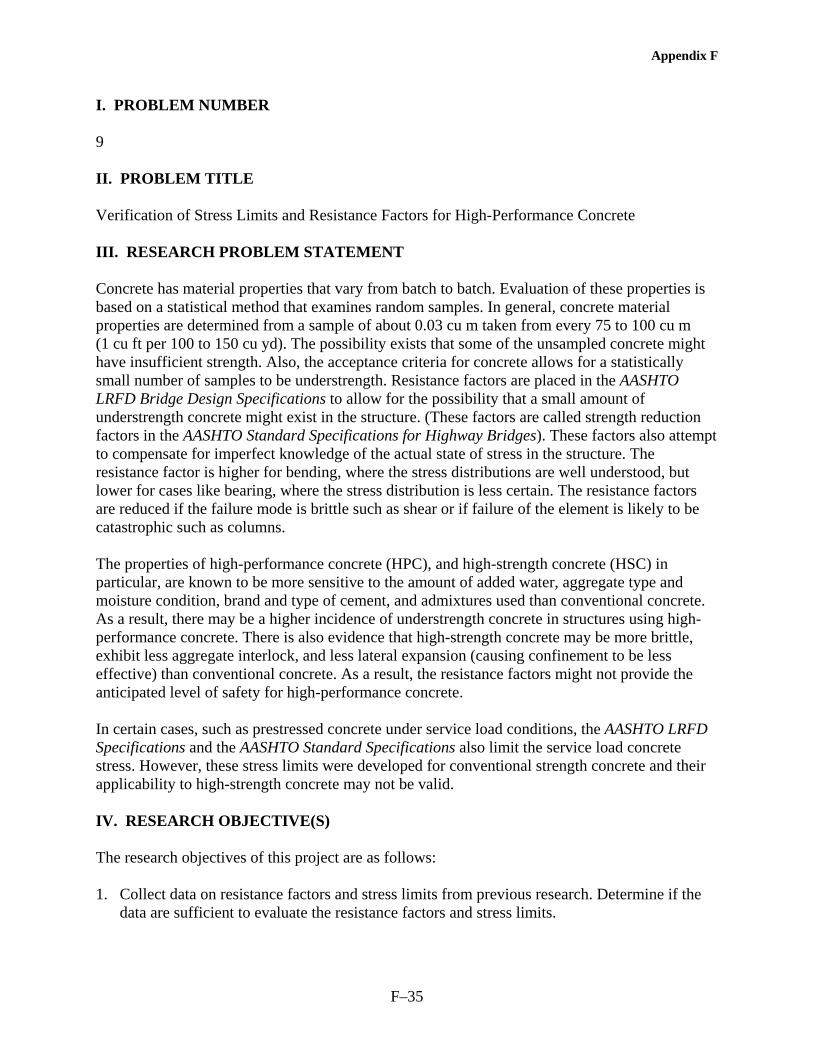
Appendix F
F–35
I. PROBLEM NUMBER 9 II. PROBLEM TITLE Verification of Stress Limits and Resistance Factors for High-Performance Concrete III. RESEARCH PROBLEM STATEMENT Concrete has material properties that vary from batch to batch. Evaluation of these properties is based on a statistical method that examines random samples. In general, concrete material properties are determined from a sample of about 0.03 cu m taken from every 75 to 100 cu m (1 cu ft per 100 to 150 cu yd). The possibility exists that some of the unsampled concrete might have insufficient strength. Also, the acceptance criteria for concrete allows for a statistically small number of samples to be understrength. Resistance factors are placed in the AASHTO LRFD Bridge Design Specifications to allow for the possibility that a small amount of understrength concrete might exist in the structure. (These factors are called strength reduction factors in the AASHTO Standard Specifications for Highway Bridges). These factors also attempt to compensate for imperfect knowledge of the actual state of stress in the structure. The resistance factor is higher for bending, where the stress distributions are well understood, but lower for cases like bearing, where the stress distribution is less certain. The resistance factors are reduced if the failure mode is brittle such as shear or if failure of the element is likely to be catastrophic such as columns. The properties of high-performance concrete (HPC), and high-strength concrete (HSC) in particular, are known to be more sensitive to the amount of added water, aggregate type and moisture condition, brand and type of cement, and admixtures used than conventional concrete. As a result, there may be a higher incidence of understrength concrete in structures using high-performance concrete. There is also evidence that high-strength concrete may be more brittle, exhibit less aggregate interlock, and less lateral expansion (causing confinement to be less effective) than conventional concrete. As a result, the resistance factors might not provide the anticipated level of safety for high-performance concrete. In certain cases, such as prestressed concrete under service load conditions, the AASHTO LRFD Specifications and the AASHTO Standard Specifications also limit the service load concrete stress. However, these stress limits were developed for conventional strength concrete and their applicability to high-strength concrete may not be valid. IV. RESEARCH OBJECTIVE(S) The research objectives of this project are as follows: 1. Collect data on resistance factors and stress limits from previous research. Determine if the
data are sufficient to evaluate the resistance factors and stress limits.

Appendix F
F–36
2. Where the data are insufficient to evaluate the resistance factors and stress limits, conduct experiments to generate the data needed.
3. Using the data from objectives 1 and 2, verify the resistance factors and stress limits in the
AASHTO LRFD Specifications. Propose changes as needed. This same data should be used to evaluate the strength reduction factors and allowable stresses in the AASHTO Standard Specifications.
The objectives can be accomplished with the following tasks: Task 1. Conduct an extensive literature search for experimental data on the strength properties
of structures and/or elements made with HPC.
Task 2. Determine from the data found in task 1 where significant gaps in the data exist.
Task 3. Where there are sufficient data from task 1, evaluate the resistance factors and stress limits. Propose changes as needed.
Task 4. Where task 2 suggests significant gaps in the data, propose experiments to provide the needed data. Where structural tests are needed, they should be full scale. Unless data are available from other sources, the experiments should be designed to generate the following results:
a. Field verification of the actual incidence of understrength HSC/HPC. b. Verification that the statistical nominal strength of HSC/HPC structural members,
after being reduced by the resistance factor, still exceeds strength design moments. c. An evaluation of the performance of HSC/HPC under service loads for cases where
stress limits are specified in the AASHTO LRFD Specifications. Task 5. Prepare an interim report summarizing the results of tasks 1-4.
Task 6. After approval of the interim report, conduct the experiments as approved.
Task 7. Verify the resistance factors and stress limits in the AASHTO LRFD Specifications. Propose changes, as needed, to the resistance factors and stress limits. Also verify or propose changes to the strength reduction factors and allowable stresses in the AASHTO Standard Specifications.
Task 8. Submit a final report.
V. ESTIMATE OF PROBLEM FUNDING AND RESEARCH PERIOD Recommended Funding: $500,000

Appendix F
F–37
Research Period: 36 months – Approximately 10 months to complete tasks 1-5, 2 months to review the interim report, 21 months to complete tasks 6-8, and 3 months to review the final report. VI. URGENCY/PRIORITY The current specifications contain barriers to the greater use of high-performance concrete and high-strength concrete. These barriers restrict the application of existing and new technology to bridges. As the industry moves towards the greater use of high-performance concrete and high-strength concrete, the need to revise the resistance factors and stress limits becomes more urgent since the current factors may not provide the anticipated level of safety. User Community Results of the research will be directly applicable to the AASHTO LRFD Bridge Design Specifications and the AASHTO Standard Specifications for Highway Bridges and will benefit the whole bridge community. Implementation Research results will be implemented with proposed revisions to the AASHTO LRFD Bridge Design Specifications and the AASHTO Standard Specifications for Highway Bridges. Effectiveness The benefits of this research include a more realistic evaluation of the actual safety factors as related to high strength/high-performance concrete. Thrust Areas/Business Needs The proposed research addresses the AASHTO Highway Subcommittee on Bridges and Structures (HSCOBS) thrust areas of Enhanced Specifications for Improved Structural Performance and/or Enhanced Materials, Structural Systems, and Technologies. The associated building blocks are specifications for high-performance materials, high-performance concrete, and performance-based acceptance criteria.


Appendix F
F–39
I. PROBLEM NUMBER 10
II. PROBLEM TITLE Confinement of High-Strength Concrete Columns for Seismic and Nonseismic Regions
III. RESEARCH PROBLEM STATEMENT The American Concrete Institute State-of-the-Art Report on High-Strength Concrete Columns (ACI 441R-3) states that the presence of transverse (confining) reinforcement increases the strength of concrete columns but, for a given amount of transverse reinforcement, the effect is less pronounced with high-strength concrete (HSC) than with conventional strength concrete. This is often attributed to HSC having less expansion of the core under high axial load. The ACI report summarizes the results of approximately 15 different studies on concentrically loaded HSC columns. The results suggest that: 1. Columns with similar values of (Ds fyt / fc') have similar axial ductilities. Note that if the
transverse steel yield strength, fyt, is constant, a larger transverse reinforcing ratio (Ds) is required for higher strength concrete.
2. For HSC columns to achieve the minimum axial load capacity calculated by the procedures
of ACI 318, (Ds fyt / fc') needs to be greater than 30 percent. However, this report has some shortcomings. Some of the tests were made using confined cylinders, not columns. While the data suggesting that (Ds fyt / fc') needs to be greater than 30 percent are based on nine sets of tests, only two sets have (Ds fyt / fc') greater than 30 percent. The report says that HPC will have acceptable levels of ductility if "certain minimum limitations are met for the volumetric ratio and spacing of transverse reinforcing," but neither the report nor the cited reference indicates the actual limitations. Finally, the presented data do not differentiate between spiral reinforced columns and tied columns. Thus, there needs to be some consistent data generated for spiral and tied columns with similar transverse reinforcing ratios and using HSC. The tests should address the minimum value of (Ds fyt / fc') needed to achieve acceptable strength and ductility in both seismic and nonseismic regions. The tests should also address the question of minimum bar size and spacing. IV. RESEARCH OBJECTIVE(S) Task 1. Complete a literature search for data on HSC columns. Divide the data into groups for
spiral and tied columns for both monotonic and cyclic loading. Also consider concentric and eccentric loadings. This search should include column like structures, such as piles. Do an analysis of the data to determine where gaps exist in the data or where there are insufficient data to draw a firm conclusion. The analysis should consider concrete with compressive strengths up to 140 MPa (20,000 psi).

Appendix F
F–40
Task 2. Submit an interim report that summarizes the literature search. Propose full-size specimens, which can be tested to fill in the data pool, as identified in task 1.
Task 3. After approval of the interim report and testing plan, test full-size specimens to determine the amount, type, arrangement, and spacing of transverse reinforcement needed to assure strength and ductility in HSC columns in both seismic and nonseismic regions. This testing program should consider concrete with compressive strengths up to 140 MPa (20,000 psi). Tied and spiral columns must be included. The effects of eccentric loading should also be tested.
Task 4. Prepare draft specifications for the AASHTO Standard Specifications for Highway Bridges and the AASHTO LRFD Bridge Design Specifications. The draft specifications should address the amount, type, arrangement, and spacing of transverse reinforcement needed to ensure strength and ductility in HSC columns under both eccentric and concentric loads.
Task 5. Prepare a final report.
V. ESTIMATE OF PROBLEM FUNDING AND RESEARCH PERIOD Recommended Funding: $500,000 Research Period: 36 months
VI. URGENCY/PRIORITY The current AASHTO specifications contain barriers to the greater use of high-strength concrete. These barriers restrict the application of existing and new technology to bridges. As the industry moves towards the greater use of high-strength concrete, the need to revise the AASHTO Standard Specifications and the AASHTO LRFD Specifications becomes more urgent. User Community Results of the research will be directly applicable to the AASHTO Standard Specifications for Highway Bridges and the AASHTO LRFD Bridge Design Specifications and will benefit the whole bridge community. Implementation Research results will be implemented with proposed revisions to the AASHTO Standard Specifications for Highway Bridges and the AASHTO LRFD Bridge Design Specifications.

Appendix F
F–41
Effectiveness The benefits of this research include: 1. Use of HSC in columns allows for the use of smaller columns, which are generally more
economical. Small columns might improve the hydraulic characteristics of underflowing waterways or provide more clearance for underpassing roadways.
2. HSC columns may be more resistant to vehicle or debris impacts. 3. HSC columns will usually be more durable than conventional strength columns. Thrust Areas/Business Needs The proposed research addresses the AASHTO Highway Subcommittee on Bridges and Structures (HSCOBS) thrust areas of Enhanced Specifications for Improved Structural Performance and/or Enhanced Materials, Structural Systems, and Technologies. The associated building blocks are specifications for high-performance materials, performance-based specifications, high-performance concrete, and performance-based acceptance criteria


G-1
APPENDIX G—REFERENCES
TABLE OF CONTENTS
SECTION PAGE
References...................................................................................................................................G–3

G-2

G-3
REFERENCES
1. Standard Specifications for Transportation Materials and Methods of Sampling and Testing, Twenty First Edition, American Association of State Highway and Transportation Officials, Washington, DC, 2001.
2. Standard Specifications for Highway Bridges, Sixteenth Edition, American Association of State Highway and Transportation Officials, Washington, DC, 1996, 677 pp.
3. 1997 Interim Revisions to the Standard Specifications for Highway Bridges, Sixteenth Edition (1996), American Association of State Highway and Transportation Officials, Washington, DC, 1997.
4. 1998 Interim Revisions to the Standard Specifications for Highway Bridges, Sixteenth Edition (1996), American Association of State Highway and Transportation Officials, Washington, DC, 1998.
5. 1999 Interim Revisions to the Standard Specifications for Highway Bridges, Sixteenth Edition (1996), American Association of State Highway and Transportation Officials, Washington, DC, 1999.
6. 2000 Interim Revisions to the Standard Specifications for Highway Bridges, Sixteenth Edition (1996), American Association of State Highway and Transportation Officials, Washington, DC, 2000.
7. AASHTO LRFD Bridge Design Specifications, Second Edition, American Association of State Highway and Transportation Officials, Washington, DC, 1998.
8. 1999 Interim AASHTO LRFD Bridge Design Specifications, Second Edition (1998), American Association of State Highway and Transportation Officials, Washington, DC, 1999.
9. 2000 Interim AASHTO LRFD Bridge Design Specifications, Second Edition (1998), American Association of State Highway and Transportation Officials, Washington, DC, 2000.
10. 2001 Interim AASHTO LRFD Bridge Design Specifications, Second Edition (1998), American Association of State Highway and Transportation Officials, Washington, DC, 2001.
11. AASHTO LRFD Bridge Construction Specifications, First Edition 1998, American Association of State Highway and Transportation Officials, Washington, DC, 1998.
12. AASHTO LRFD Bridge Construction Specifications, 1999 Interim Edition, American Association of State Highway and Transportation Officials, Washington, DC, 1999.
13. AASHTO LRFD Bridge Construction Specifications, 2000 Interim Edition, American Association of State Highway and Transportation Officials, Washington, DC, 2000.

G-4
14. AASHTO LRFD Bridge Construction Specifications, 2001 Interim Edition, American Association of State Highway and Transportation Officials, Washington, DC, 2001.
15. ACI Committee 363, “State-of-the-Art Report on High-Strength Concrete (ACI 363R-92),” American Concrete Institute, Farmington Hills, MI, 1992, 55 pp.
16. ACI Committee 363, “Guide to Quality Control and Testing of High-Strength Concrete (ACI 363.2R-98),” American Concrete Institute, Farmington Hills, MI, 1998, 18 pp.
17. ACI Committee 211, “Guide for Selecting Proportions for High-Strength Concrete with Portland Cement and Fly Ash (ACI 211.4R-93),” American Concrete Institute, Farmington Hills, MI, 1993, 13 pp.
18. ACI Committee 318, “Building Code Requirements for Structural Concrete (318-02) and Commentary (318R-02),” American Concrete Institute, Farmington Hills, MI, 2002, 443 pp.
19. Tikalsky, P.J. and Carrasquillo, R.L., “Fly Ash Evaluation and Selection for Use in Sulfate Resistant Concrete,” ACI Materials Journal, Vol. 90, No. 6, November–December 1993, pp. 545–551.
20. Prowell, B.D. and Weingart, R., “Precisions of Flat and Elongated Particle Tests, ASTM D4791 and VDG-40 Videograder,” Transportation Research Record No. 1673, Geomaterials, Transportation Research Board, 1999, pp. 73–80.
21. Ferraris, C.F., “Measurement of Rheological Properties of High Performance Concrete: State of the Art Report,” NISTIR 5869, National Institute of Standards and Technology, Gaithersburg, MD, 1996, 34 pp.
22. Lobo, C.L., Mullings, G.M., and Gaynor, R.D., “Effect of Capping Materials and Procedures on the Measured Compressive Strength of High Strength Concrete,” Cement, Concrete and Aggregates, Vol. 16, No. 2, December 1994, pp. 173–180.
23. Ozyildirim, C., “Permeability Specifications for High-Performance Concrete Decks,” Transportation Research Record No. 1610, Concrete in Construction, Transportation Research Board, Washington, 1998, DC, pp. 1–5.
24. Nordtest, “NT Build 443 Concrete, Hardened: Accelerated Chloride Penetration,” Espoo, Finland, 5 pp.
25. Detwiler, R.J., Kojundic, T., and Fidjestol, P., “Evaluation of Bridge Deck Overlays,” Concrete International, Vol. 19, No. 8, August 1997, pp. 43–45.
26. Myers, J.J., “How to Achieve a Higher Modulus of Elasticity,” HPC Bridge Views, Issue No. 5, September/October 1999, pp. 3.
27. ACI Committee 441, “High-Strength Concrete Columns: State-of-the-Art (ACI 441R-96),” American Concrete Institute, Farmington Hills, MI, 1997, 13 pp.

G-5
28. Canadian Standards Association, “CSA A23.3-94 Design of Concrete Structures,” Rexdale, ON, Canada 1994, 199 pp.
29. Azizinamini, A., Pavel, R., Hatfield, E., and Ghosh, S.K., “Behavior of Lap-Spliced Reinforcing Bars Embedded in High-Strength Concrete,” ACI Structural Journal, Vol. 96, No. 5, September-October 1999, pp. 826–835.
30. Lane, S.N., “A New Development Length Equation for Pretensioned Strands in Bridge Beams and Piles,” FHWA, U.S. Department of Transportation, Report No. FHWA-RD-98-116, 1998, 131 pp.
31. Goodspeed, C.H., Vanikar, S., and Cook, R., “High Performance Concrete Defined for Highway Structures,” Concrete International, Vol. 18, No. 2, February 1996, pp. 62–67.
32. High Performance Concrete, Compact Disc, Federal Highway Administration, Version 3.0, February 2003.
33. Russell, H.G., “ACI Defines High-Performance Concrete,” Concrete International, Vol. 21, No. 2, February 1999, pp. 56–57.
34. Mather, B., “How to Make Concrete that Will Be Immune to the Effects of Freezing and Thawing,” Paul Klieger Symposium on Performance of Concrete, ACI SP-122, American Concrete Institute, Farmington Hills, MI, 1990, pp. 1–18.
35. Cordon W.A., “Freezing and Thawing of Concrete-Mechanisms and Control,” ACI Monograph No. 3, American Concrete Institute, Farmington Hills, Michigan, 1966.
36. Janssen D.J. and Snyder M.B., “Resistance of Concrete to Freezing and Thawing,” SHRP-C-391, Strategic Highway Research Program, National Research Council, 1994, 201 pp.
37. Schwartz, D.R., “D-Cracking of Concrete Pavements,” NCHRP Synthesis of Highway Practice No 134, Transportation Research Board, 1987, 34 pp.
38. Newlon, H.H. and Mitchell T.M., “Freezing and Thawing,” Significance of Tests and Properties of Concrete and Concrete-Making Materials, STP 169C, American Society for Testing and Materials, West Conshohocken, PA, 1994, pp. 153–163.
39. Newlon, H.H., “Modification of ASTM C 666 for Testing Resistance of Concrete to Freezing and Thawing in Sodium Chloride Solution,” VHTRC 79-R16, Virginia Transportation Research Council, Charlottesville, VA, 1978, 19 pp.
40. Neville, A.M., Properties of Concrete, Fourth and Final Edition, John Wiley & Sons, Inc., New York, NY, 1996.
41. ACI Committee 116, “Cement and Concrete Terminology, (ACI 116R)” American Concrete Institute, Farmington Hills, MI, 2000, 73 pp.

G-6
42. ACI Committee 201, “Guide to Durable Concrete, ACI 201.2R,” American Concrete Institute, Farmington Hills, MI, 1992, 39 pp.
43. Liu, T., “Abrasion Resistance,” Significance of Tests and Properties of Concrete and Concrete-Making Materials, STP 169C, American Society for Testing and Materials, West Conshohocken, PA, 1994, pp. 182–191.
44. Tikalsky, P.J. and Scanlon, A., High-Performance Concrete, Pennsylvania Transportation Institute, University Park, PA, 2000, 68 pp.
45. ACI Committee 325, “Texturing Concrete Pavements (ACI 325.6R),” American Concrete Institute, Farmington Hills, MI, 1988, 10 pp.
46. Byrd L.D., “Effect of Studded Tires,” NCHRP Synthesis 32, Transportation Research Board, Washington, DC, 1975.
47. Ozyildirim, C., “Durability of Concrete Bridges in Virginia,” ASCE Structures XI Proceedings: Structural Engineering in Natural Hazards Mitigation, American Society of Civil Engineers, New York, NY, 1993, pp. 996–1001.
48. Whiting, D., “Rapid Determination of the Chloride Permeability of Concrete,” Federal Highway Administration, FHWA/RD-81/119, 1981, 174 pp.
49. Ozyildirim, C., “Rapid Chloride Permeability Testing of Silica Fume Concrete,” Cement, Concrete, and Aggregate, Vol. 16, No. 1, 1994, pp. 53–56.
50. Hooton, R.D., Thomas, M.D.A., and Stanish, K., “Prediction of Chloride Penetration in Concrete,” FHWA, U.S. Department of Transportation, Report No. FHWA-RD-00-142, 2001, 412 pp.
51. Stark, D., “Alkali-Silica Reactions in Concrete,” Significance of Tests and Properties of Concrete and Concrete-Making Materials, STP 169C, American Society for Testing and Materials, West Conshohocken, PA, 1994, pp. 365–371.
52. Tuthill, L.H., “Alkali-Silica Reaction—40 Years Later,” Concrete International: Design and Construction, Vol. 10, No. 12, December 1982, pp. 24–26.
53. Lane, D.S., “Comparison of Results from C 441 and C 1293 with Implications for Establishing Criteria for ASR-Resistant Concrete,” Cement, Concrete, and Aggregates, Vol. 1, No. 2, 1999, pp. 149–156.
54. Fournier, B. and Malhotra, M., “Evaluation of Laboratory Test Methods for Alkali-Silica Reactivity,” Cement, Concrete, and Aggregates, Vol. 1, No. 2, 1999, pp. 173–184.
55. Lea, F.M., The Chemistry of Cement and Concrete, lst American Edition, Chemical Publishing Company, New York, 1971.

G-7
56. DePuy, G.W., “Chemical Resistance of Concrete,” Significance of Tests and Properties of Concrete and Concrete-Making Materials, STP 169C, American Society for Testing and Materials, West Conshohocken, PA, 1994, pp. 263–281.