complementary code keying modulation and frequency domain ... · even hundreds of symbols. thus,...
TRANSCRIPT
Abstract—In this paper, we investigate the single carrier
modulation and detection schemes for medium range underwater
acoustic communication with severe inter-symbol interference (ISI)
and ocean ambient noise. Complementary code keying (CCK), a
variation of M-ary bi-orthogonal keying, is used as the modulation
scheme. The CCK modulation with good auto-correlation and
cross-correlation properties provides a strong tolerance to ISI caused
by multipath distortion and supports high data rate transmission. In
addition, we propose the low complexity method of frequency
domain equalization applied to single carrier system. Two types of
channel estimation algorithms, least squares (LS) and matching
pursuit (MP), are also implemented. We present performance analysis
on bit error rate (BER) for different detection schemes. The ocean
experiment results show that a reliable communication over 10
kilometers underwater transmission is achieved with a data rate at 4
kbit/s in 4 kHz of bandwidth.
Keywords—Channel estimation, complementary code keying
(CCK), frequency domain equalization, underwater acoustic
communication.
I. INTRODUCTION
VER the past few decades, there have been a number of
activities in the area of underwater acoustic
communications. An underwater acoustic channel is
characterized as a multipath propagation, frequency-selective
fading, limited available bandwidth, and ambient ocean
acoustic noise channel [1]. These characteristics result in that
high data rates reliable transmission in the underwater acoustic
channel is very challenging [2]. It is generally recognized as
one of the most difficult digital communication channel. In
underwater acoustic communication, the long delay spread,
which cause inter-symbol interference (ISI), may spoil tens or
This work was supported in part by the National Natural Science
Foundation of China (No. 61301097, No. 61671398 and No. 61471308).
Xialin Jiang is with the Key Laboratory of Underwater Acoustic
Communication and Marine Information Technology Ministry of Education,
Xiamen University, Xiamen, Fujian, China 361005 (email:
Wei Su is with the Key Laboratory of Underwater Acoustic
Communication and Marine Information Technology Ministry of Education,
Xiamen University, Xiamen, Fujian, China 361005 (corresponding author,
email: [email protected]).
En Cheng is with the Key Laboratory of Underwater Acoustic
Communication and Marine Information Technology Ministry of Education,
Xiamen University, Xiamen, Fujian, China 361005 (email:
even hundreds of symbols. Thus, some sort of anti-ISI
technique is needed to combat the channel distortion. To
improve performance of data detection and obtain the high data
rates communications over the band-limited underwater
acoustic channels, orthogonal frequency-division multiplex
(OFDM) has been applied as effective anti-multipath technique
to underwater acoustic communications [3][4]. With the very
special structure, the OFDM system can efficiently combat
with ISI and distortion caused by multipath propagation.
Additionally, another key feature that has made OFDM system
popular in communication systems is that it allows a very low
complexity frequency domain equalization (FDE) method via
Discrete Fourier Transform (DFT) algorithm. However, high
peak-to-average-power ration (PAPR) and sensitive to carrier
frequency offset (CFO), which causes inter carrier interference
(ICI), are major challenges with OFDM system.
An alternative to the OFDM approach, more traditional
single carrier (SC) system with advanced modulation and
detection techniques has comparable performance and low
complexity. SC system uses a single carrier, instead of
multi-carriers in OFDM system. Therefore, the
peek-to-average power is much lower for single carrier system
compared with OFDM system.
In the realm of single carrier system, research work has been
active on modulation and detection techniques. In this paper,
we design a single-carrier underwater acoustic communication
system using complementary code keying (CCK) modulation
[5][6][7] and frequency domain equalization techniques
[8][9][10]. CCK modulation technique, which is adopted by
IEEE 802.11b standard, with good auto-correlation and
cross-correlation properties, provides a strong tolerance to
multipath distortion and supports high data rates transmission.
Transmissions over long memory underwater acoustic channel,
time domain equalization technique has the disadvantages of
high computational complexity. Compared to time domain
equalization, single carrier frequency domain equalizers
(SC-FDEs) can effectively reduce the computational
complexity by converting the received signals from time
domain to frequency domain. Similar to OFDM, the frequency
domain equalization in SC system is conducted block-by-block
via DFT and inverse DFT (IDFT) operations. Hence, SC-FDE
system achieves the similar complexity and performance as
OFDM system.
Complementary Code Keying Modulation and
Frequency Domain Equalization for Single
Carrier Underwater Acoustic Communications
Xialin Jiang, Wei Su*, and En Cheng
O
INTERNATIONAL JOURNAL OF CIRCUITS, SYSTEMS AND SIGNAL PROCESSING Volume 10, 2016
ISSN: 1998-4464 339
The rest of the paper is organized as follows. In section II,
we describe the system model of an underwater acoustic
transmission system. In section III, we present the SC-FDE
system employing the CCK modulation technique. We present
experimental results and discussions in section IV. Finally, we
draw conclusions in section V.
II. SYSTEM MODEL
In this section, we present the system model for underwater
acoustic communications. At the receiver end, the passband
receive signals are generally down-converted to the equivalent
baseband signals. The baseband models are usually used for
further signal processing algorithms, because they are more
mathematically tractable than passband signals.
In underwater acoustic communications systems, the
transmitted signals typically propagate different paths from
transmitter to receiver. This arises from sound reflection at the
water surface, bottom and other objects, and sound refraction
in the water. It is commonly known as multipath propagation.
At the receiver, the multipath propagation results in filtering
effect on the transmitted signals. In this paper, we assume
down-conversion, carrier synchronization, and timing recovery
are operated flawlessly, such that the underwater acoustic
channel can be approximated by a discrete time equivalent
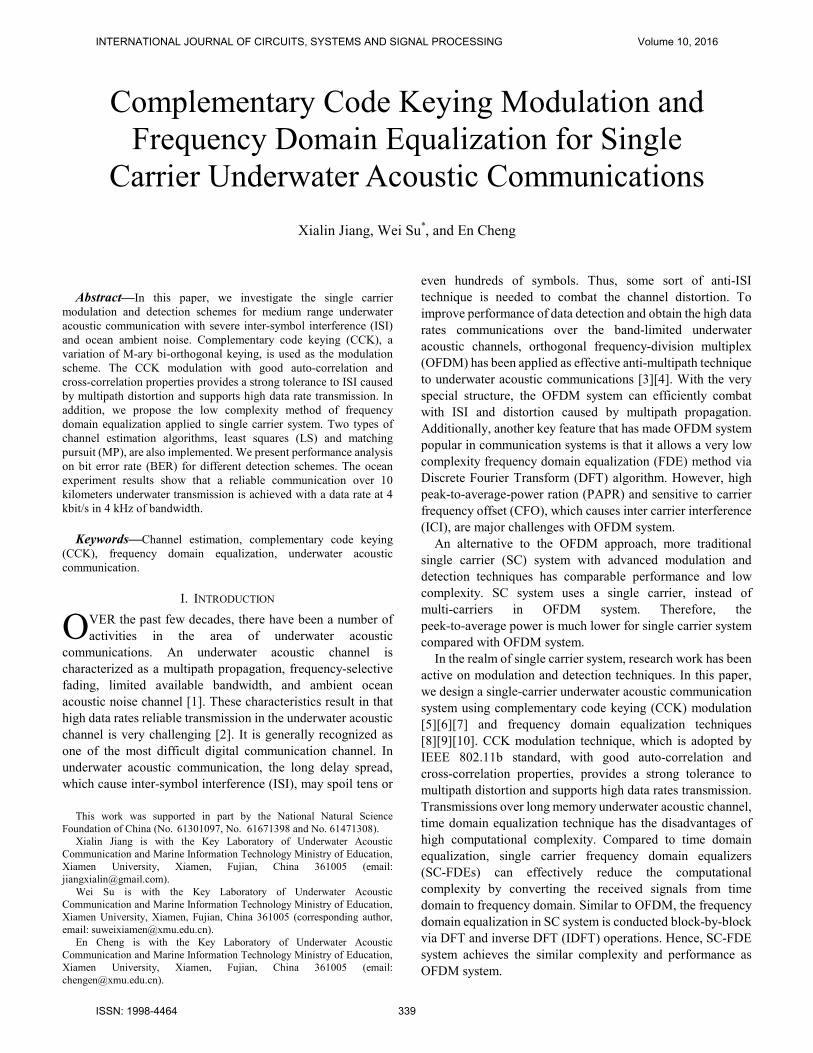
baseband model, as shown in Fig. 1, where the underwater
acoustic channel is modelled as a time-invariant FIR (finite
impulse response) filter. While the underwater acoustic
channel may actually be time-varying, if the variations are
much slower than the data rate, the underwater acoustic
channel can be viewed as time-invariant for each DFT block
time scale.
Fig. 1 representation of an underwater acoustic transmission system
The transmit-receive equivalent baseband signals relation in
the time domain can be expressed as:
y h x w= ∗ + , (1)
Where ∗ denotes the convolution operation, y is the
time-domain channel received signal, h is the channel impulse
response, x is the time-domain transmitted signal, and w is the
additive noise. In an SC-FDE system, the time-domain
received signal is converted to frequency domain via DFT in
the receiver end.
III. SC-FDE SYSTEM EMPLOYING CCK MODULATION
In this section, we propose the CCK modulation technique
that works in conjunction with frequency domain equalization
for a single carrier underwater acoustic communication system.
A. SC-FDE System Structure
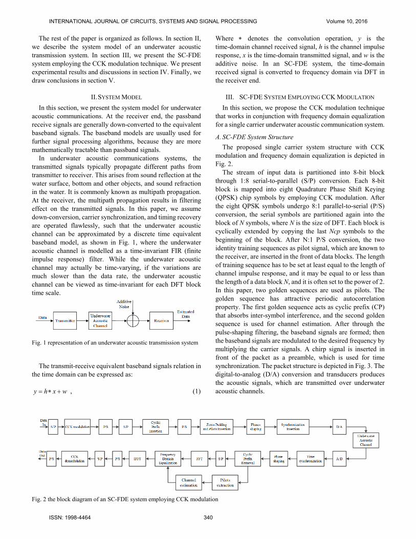
The proposed single carrier system structure with CCK
modulation and frequency domain equalization is depicted in
Fig. 2.
The stream of input data is partitioned into 8-bit block
through 1:8 serial-to-parallel (S/P) conversion. Each 8-bit
block is mapped into eight Quadrature Phase Shift Keying
(QPSK) chip symbols by employing CCK modulation. After
the eight QPSK symbols undergo 8:1 parallel-to-serial (P/S)
conversion, the serial symbols are partitioned again into the
block of N symbols, where N is the size of DFT. Each block is
cyclically extended by copying the last Ncp symbols to the
beginning of the block. After N:1 P/S conversion, the two
identity training sequences as pilot signal, which are known to
the receiver, are inserted in the front of data blocks. The length
of training sequence has to be set at least equal to the length of
channel impulse response, and it may be equal to or less than
the length of a data block N, and it is often set to the power of 2.
In this paper, two golden sequences are used as pilots. The
golden sequence has attractive periodic autocorrelation
property. The first golden sequence acts as cyclic prefix (CP)
that absorbs inter-symbol interference, and the second golden
sequence is used for channel estimation. After through the
pulse-shaping filtering, the baseband signals are formed; then
the baseband signals are modulated to the desired frequency by
multiplying the carrier signals. A chirp signal is inserted in
front of the packet as a preamble, which is used for time
synchronization. The packet structure is depicted in Fig. 3. The
digital-to-analog (D/A) conversion and transducers produces
the acoustic signals, which are transmitted over underwater
acoustic channels.
Fig. 2 the block diagram of an SC-FDE system employing CCK modulation
INTERNATIONAL JOURNAL OF CIRCUITS, SYSTEMS AND SIGNAL PROCESSING Volume 10, 2016
ISSN: 1998-4464 340

Fig. 3 packet structure of SC-FDE.
In the receiver, the signals at the output of the underwater
acoustic channel undergo transducer/hydrophone conversion,
analog-to-digital (A/D) conversion, and frequency down
conversion. The time synchronization finds the start of the
transmitted signal, and produces a sequence of noisy symbols
whose length is equal to the transmitted data block. The CP of
each data block is discarded. The rest of the block is sent to the
DFT which converts the time domain symbols into frequency
domain. The Frequency domain equalization combats with
inter-symbol interference. The output results of frequency
domain equalization are converted back to the time domain.
Finally, symbols-to-bits and data decisions are made after CCK
demodulation.
B. CCK Modulation
Complementary Code Keying is developed by Intersil and
Lucent Technologies and is adopted as the modulation scheme
of the IEEE 802.11 Standard for high-rate spread-spectrum
communications (5.5 and 11 Mbps) at 2.4 GHz band. In this
paper, the CCK modulation scheme we use is based on IEEE
802.11 11Mbps mode.
CCK is an M-ary orthogonal keying modulation method,
where one of the M unique (almost orthogonal) signal code
words are chosen carefully for transmission. The CCK has a
code length of eight. The eight-chip CCK code words are
defined as follows:
{ }2 3 4 3 4 2 3 31 2 4 4 2( + + ) ( + ) ( + )( + ), , , , , , ,1j j j jj j j jC e e e e e e e eϕ ϕ ϕ ϕ ϕ ϕ ϕ ϕϕ ϕ ϕ ϕ ϕ= − − (2)
where C is the code word. As shown in (2), the CCK code word
is determined by the four phase parameters 1ϕ , 2ϕ , 3ϕ , 4ϕ and,
where 1ϕ is contained in all eight chips, 2ϕ is contained in all
the odd chips, 3ϕ is contained in all odd pairs of chips, and 4ϕ
is contained in all odd quads of chips. To begin, the information
bits are partitioned into 8-bit block as ( )0 1 7, , ,d d d… . The eight
bits encode the four phase parameters according to the scheme
shown in Table I.
Table I. phase parameters encoding
dibits phase parameter
0 1d d
1ϕ
2 3d d
2ϕ
4 5d d
3ϕ
6 7d d
4ϕ
The first two bits 0
d and 1
d encode the phase 1
ϕ based on
differential quadrature phase shift keying (DQPSK) modulation
as specified in Table II, i.e., the phase 1
ϕ is relative to the phase
1ϕ in the previous symbol.
Table II DQPSK encoding
0 1d d
1ϕ of Even symbols
1ϕ of Odd symbols
00 0 π
01 / 2π - / 2π
11 π 0
10 - / 2π / 2π
The dibits (2
d3
d ), (4
d5
d ), and (6
d7
d ) encode the phase
2ϕ , 3
ϕ , and 4ϕ based on QPSK modulation, respectively, as
shown in Table III.
Table III QPSK encoding.
dibit (1i i
d d + ) phase
00 0
01 / 2π
10 π
11 - / 2π
In CCK modulation, it takes 8 information bits to define each
code word of an 8 complex chips. The 8 chips are QPSK
symbols. Hence, there have 84 =65536 possible code words for 8
information bits. Actually, the CCK modulation choses 82 =256
code words from 65536 possible code words pool. With the
large set of good codes to pick, the CCK modulation provides a
strong tolerance to multipath distortion due to the large coding
distance.
C. Frequency Domain Equalization
The frequency domain equalization in single carrier system
makes use of the property of DFT to design a block data
structure. To perform the frequency domain equalization, the
stream of transmit data symbols is partitioned into the block size
of N symbols. In generally, a guard interval of a length equal or
greater to the duration of the channel impulse response is
inserted at the beginning of each block. Moreover, the guard
interval is often the repetition of last Ncp symbols of each block.
It is so called cyclic prefix (CP). It acts as a guard interval that
eliminates the inter-symbol interference (ISI) from the previous
symbols, but also plays a key role in the task of frequency
domain equalization. Because of the choice of the CP, the linear
convolution between transmitted signal and the channel impulse
response can be modelled as circular convolution.
Consequently, frequency domain equalization can be performed
by taking the DFT of each block of received signal, applying
equalizer to remove the ISI effects in the frequency domain, and
converting the results back to the time domain via IDFT.
INTERNATIONAL JOURNAL OF CIRCUITS, SYSTEMS AND SIGNAL PROCESSING Volume 10, 2016
ISSN: 1998-4464 341
We consider the case that a block of signal
1 2[ , ,..., ]T
Nx x x=x is passed through the underwater acoustic
channel with the length of M impulse response
1 2[ , ,..., ]T
Mh h h=h , where T represents the matrix transpose. It
is assumed that the size of block N is larger than the length of
channel impulse response M. The noise signal is
1 2[ , ,..., ]T
Nw w w=w . The received signal 1 2[ , ,..., ]T
Ny y y=y
is obtained by convoluting x and the vector of the channel
impulse response, h. It is written in a matrix form as
= +y Hx w , (3)
where H is the time-domain channel matrix, it is a N-by-N
circular square matrix whose first column is given by the
channel impulse response h with a number of zeros padding to
the end to extend its length to the block size of N.
1 1 2 2
2 1 1 3
3 2 1 1
1 2 3 1
0 0
0 0
0
0 0
M M M
M M
M M
M M M M
h h h h h
h h h h h
h h h h h
h h h h h
− −
−
−
− − −
=
H
⋯ ⋯
⋱ ⋯
⋱ ⋱ ⋯
⋮ ⋮ ⋱ ⋱ ⋱ ⋱ ⋱ ⋱ ⋮
⋮ ⋮ ⋱ ⋱ ⋱ ⋱ ⋱ ⋱ ⋮
⋯ ⋯
(4)
According to the feature of circular matrices, every circular
matrix H can be diagonalized by the DFT matrix. The N-by-N
DFT matrix defined as
2
2 4 2 ( 1)
4 8 4 ( 1)
2 ( 1) 4 ( 1) 2 ( 1)
1 1 1 1
1
1
1
Nj j j
N N N
Nj j j
N N N
N N Nj j j
N N N
e e e
e e e
e e e
π π π
π π π
π π π
−− − −
−− − −
− − −− − −
=
F
⋯
⋯
⋯
⋮ ⋮ ⋮ ⋱ ⋮
⋯
(5)
Applying the DFT on either side of (4), we get the
= -1Λ FHF , (6)
where F-1
is the inverse discrete Fourier transform, and Λ is the
diagonal matrix whose eigenvalues are also given by taking the
fast Fourier transform of the first column of H.
We define the frequency transformed vectors as
Y = Fy, X = Fx, W = Fw , (7)
The frequency domain transmit-receive relation is derived
from the time domain transmit receive relation by applying the
discrete Fourier transform on both side of the (3):
1−= +Fy FHF Fx Fw , (8)
Y = ΛX + W , (9)
For a time invariant frequency selective channel with severe
ISI, the channel matrix in the frequency domain Λ is diagonal.
The entries of the diagonal matrix Λ can be denoted the channel
attenuations in the frequency domain. The trivial equalization is
done by pointwise division of the receive signal by the
corresponding channel attenuations in the frequency domain.
This method of equalization is known as zero-forcing (ZF)
equalization [11][12]. Without any further statistical
information about transmitted signal and channel, the
zero-forcing equalization is the solution for the least squares
problem. The frequency domain of zero-forcing equalization
can be expressed as:
1 1 1− − −= =x F X F Λ Y , (10)
The zero-forcing equalization ignores the presence of
additive noise. Its use may result in significant noise
enhancement at those frequencies where channel frequency
response has spectral nulls. To avoid such noise
enhancement, an alternative is to adopt the minimum
mean-squared error (MMSE) equalizer which minimizes the
error between the transmitted symbols and the output of
equalizer. The MMSE equalizer requires the second order
statistical information about the noise signal and the
transmitted signal, and provides a tradeoff between noise
enhancement and ISI removal. The frequency domain of MMSE
equalization can be expressed as
1 1 11( )
SNR
− − ∗ −= = +x F X F ΛΛ I ΛY (11)
where I is an N×N identity matrix, and SNR is the
signal-to-noise ratio at the input of MMSE equalizer.
Zero-forcing equalizer and MMSE equalizer are both linear
equalizers and simple to implement, because the inversion of a
diagonal matrix is easy to calculate. In addition, the DFT and
IDFT operations can be implemented using the computationally
efficient fast Fourier transform (FFT) and inverse FFT (IFFT)
algorithms. However, there performance is not enough for
underwater acoustic channels having spectral nulls. An obvious
choice for underwater acoustic channels with sever ISI is a
non-linear equalizer.
A decision feedback equalizer (DFE) is a nonlinear
equalizer which employs previous decisions to estimate the
current symbol with a symbol-by-symbol detector. The DFE
consists of two filters. The first one is called a feedforward filter.
The second one is called a feedback filter. Its input is the
decision of the previous symbols from the detector. There are
different variations of DFEs. In this paper, we focus on the
hybrid time-frequency domain DFE approach, which uses
frequency domain filtering only for the feedforward filter, and
INTERNATIONAL JOURNAL OF CIRCUITS, SYSTEMS AND SIGNAL PROCESSING Volume 10, 2016
ISSN: 1998-4464 342
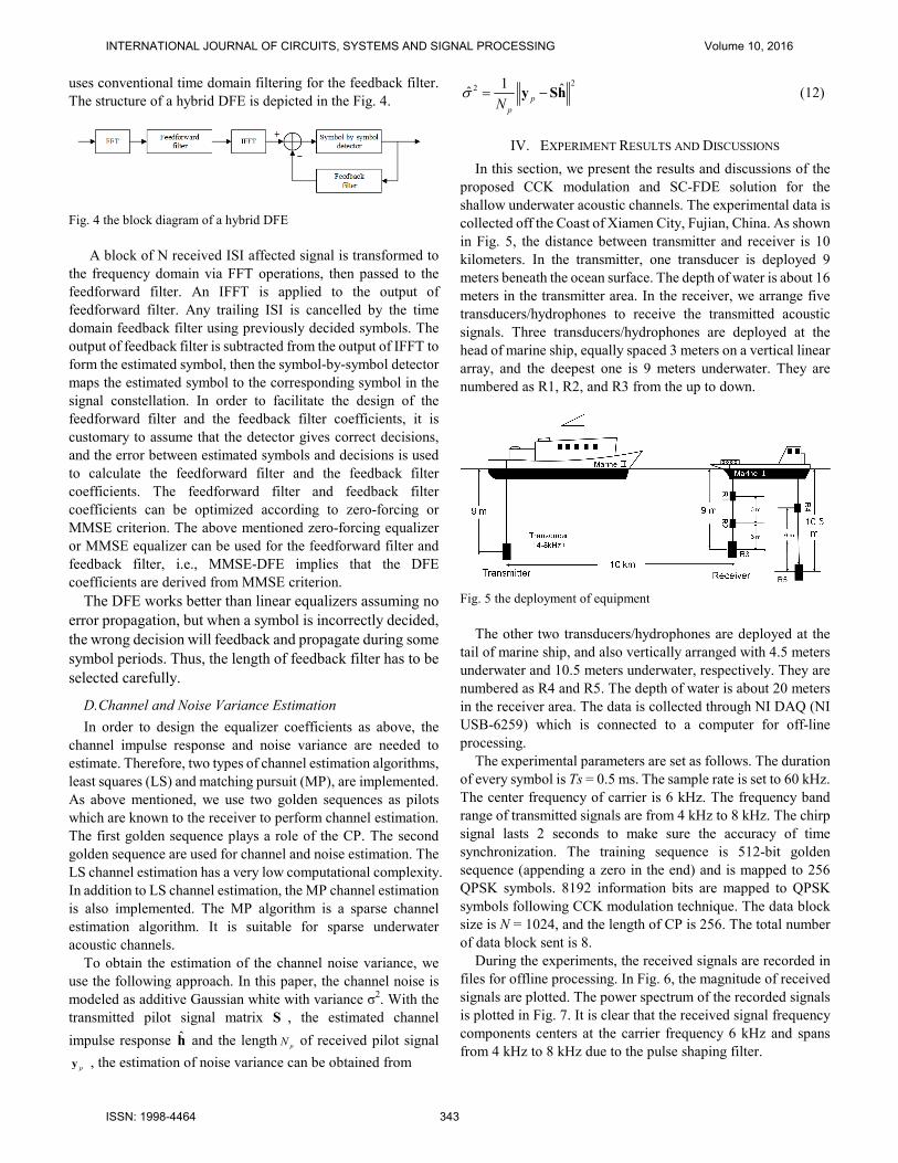
uses conventional time domain filtering for the feedback filter.
The structure of a hybrid DFE is depicted in the Fig. 4.
Fig. 4 the block diagram of a hybrid DFE
A block of N received ISI affected signal is transformed to
the frequency domain via FFT operations, then passed to the
feedforward filter. An IFFT is applied to the output of
feedforward filter. Any trailing ISI is cancelled by the time
domain feedback filter using previously decided symbols. The
output of feedback filter is subtracted from the output of IFFT to
form the estimated symbol, then the symbol-by-symbol detector
maps the estimated symbol to the corresponding symbol in the
signal constellation. In order to facilitate the design of the
feedforward filter and the feedback filter coefficients, it is
customary to assume that the detector gives correct decisions,
and the error between estimated symbols and decisions is used
to calculate the feedforward filter and the feedback filter
coefficients. The feedforward filter and feedback filter
coefficients can be optimized according to zero-forcing or
MMSE criterion. The above mentioned zero-forcing equalizer
or MMSE equalizer can be used for the feedforward filter and
feedback filter, i.e., MMSE-DFE implies that the DFE
coefficients are derived from MMSE criterion.
The DFE works better than linear equalizers assuming no
error propagation, but when a symbol is incorrectly decided,
the wrong decision will feedback and propagate during some
symbol periods. Thus, the length of feedback filter has to be
selected carefully.
D. Channel and Noise Variance Estimation
In order to design the equalizer coefficients as above, the
channel impulse response and noise variance are needed to
estimate. Therefore, two types of channel estimation algorithms,
least squares (LS) and matching pursuit (MP), are implemented.
As above mentioned, we use two golden sequences as pilots
which are known to the receiver to perform channel estimation.
The first golden sequence plays a role of the CP. The second
golden sequence are used for channel and noise estimation. The
LS channel estimation has a very low computational complexity.
In addition to LS channel estimation, the MP channel estimation
is also implemented. The MP algorithm is a sparse channel
estimation algorithm. It is suitable for sparse underwater
acoustic channels.
To obtain the estimation of the channel noise variance, we
use the following approach. In this paper, the channel noise is
modeled as additive Gaussian white with variance σ2. With the
transmitted pilot signal matrix S , the estimated channel
impulse response h and the lengthpN of received pilot signal
py , the estimation of noise variance can be obtained from
22 1 ˆˆ
p
pN
σ = −y Sh (12)
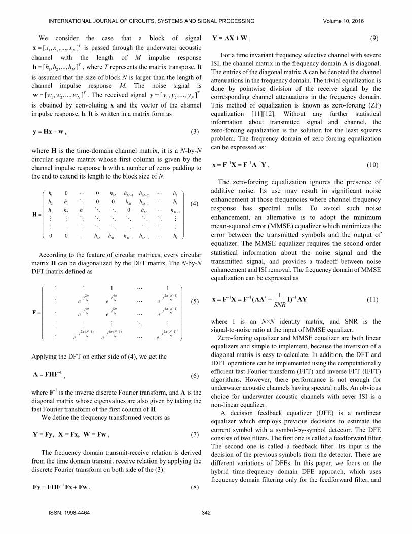
IV. EXPERIMENT RESULTS AND DISCUSSIONS
In this section, we present the results and discussions of the
proposed CCK modulation and SC-FDE solution for the
shallow underwater acoustic channels. The experimental data is
collected off the Coast of Xiamen City, Fujian, China. As shown
in Fig. 5, the distance between transmitter and receiver is 10
kilometers. In the transmitter, one transducer is deployed 9
meters beneath the ocean surface. The depth of water is about 16
meters in the transmitter area. In the receiver, we arrange five
transducers/hydrophones to receive the transmitted acoustic
signals. Three transducers/hydrophones are deployed at the
head of marine ship, equally spaced 3 meters on a vertical linear
array, and the deepest one is 9 meters underwater. They are
numbered as R1, R2, and R3 from the up to down.
Fig. 5 the deployment of equipment
The other two transducers/hydrophones are deployed at the
tail of marine ship, and also vertically arranged with 4.5 meters
underwater and 10.5 meters underwater, respectively. They are
numbered as R4 and R5. The depth of water is about 20 meters
in the receiver area. The data is collected through NI DAQ (NI
USB-6259) which is connected to a computer for off-line
processing.
The experimental parameters are set as follows. The duration
of every symbol is Ts = 0.5 ms. The sample rate is set to 60 kHz.
The center frequency of carrier is 6 kHz. The frequency band
range of transmitted signals are from 4 kHz to 8 kHz. The chirp
signal lasts 2 seconds to make sure the accuracy of time
synchronization. The training sequence is 512-bit golden
sequence (appending a zero in the end) and is mapped to 256
QPSK symbols. 8192 information bits are mapped to QPSK
symbols following CCK modulation technique. The data block
size is N = 1024, and the length of CP is 256. The total number
of data block sent is 8.
During the experiments, the received signals are recorded in
files for offline processing. In Fig. 6, the magnitude of received
signals are plotted. The power spectrum of the recorded signals
is plotted in Fig. 7. It is clear that the received signal frequency
components centers at the carrier frequency 6 kHz and spans
from 4 kHz to 8 kHz due to the pulse shaping filter.
INTERNATIONAL JOURNAL OF CIRCUITS, SYSTEMS AND SIGNAL PROCESSING Volume 10, 2016
ISSN: 1998-4464 343

0 2 4
x 105
-0.2
-0.1
0
0.1
0.2
0.3
Fig.6 the received signals.
To recover the transmitted signals, the synchronization is
necessary. The synchronization is obtained by correlating the
received signals with a local chirp signal and the peak of
correlation is the start of transmitted sequence.
0 5000 10000 15000-150
-100
-50
0
50
Frequency
Power Spectrum Magnitude (dB)
Fig. 7 the power spectrum magnitude of received signals.
For the channel estimation, we adopt the conventional LS
algorithm and MP algorithm. To make comparison, we list the
bit error rates (BER) for LS and MP channel estimation in table
IV. The hybrid MMSE-DFE is used for both two channel
estimation algorithms.
Table IV BER results of channel estimations. Hybrid MMSE-DFE
is used.
#Hydrophones LS algorithm MP algorithmta
R1 47% 3.87%
R2 0.78% 0.09%
R3 0.37% 0.05%
R4 34% 1.53%
R5 0.61% 0
The first column is the tag of five hydrophones/transducers.
The LS channel estimation generates a slightly higher BER than
the MP channel estimation with the data collected from the
hydrophones R2, R3, and R5. With the low SNR conditions,
such as data collected from the hydrophones R1 and R4, the data
cannot recover correctly with LS channel estimation.
With the MP channel estimation and noise variance
estimation, the three frequency domain equalization methods,
ZF equalizer, MMSE equalizer and hybrid MMSE-DFE
equalizer can be performed. To demonstrate the performance of
equalization, we report BER results for the three frequency
domain equalization methods in Table V. The MP channel
estimation algorithm is used.
Table V BER results of equalization. MP channel estimation is
used.
#Hydro-
phones
ZF
Equalizer
MMSE
Equalizer
Hybrid
MMSE-DFE
R1 45.96% 45.87% 3.87%
R2 5.04% 5.04% 0.09%
R3 4.76% 4.7% 0.05%
R4 38.92% 38.9% 1.53%
R5 3.2% 3.2% 0
With good channel condition, such as data collected from
hydrophone R2, R3 and R4, the SC-FDE system with hybrid
MMSE-DFE equalizer can achieve nearly zero error
transmission. That means reliable underwater acoustic
communications are obtained with data rate at 4 kbits/s in 4 kHz
of bandwidth. The performance of hybrid MMSE-DFE
equalizer is the best. The linear equalizers, Zero-force equalizer
and MMSE equalizer, cannot eliminate channel distortion
efficiently when channel has spectral nulls, such as the data
collected from R1 and R4. To demonstrate the performance of
equalization, the estimated QPSK symbols at the output of the
three equalizers are demonstrated in Fig. 8. The data is collected
from R2.
Fig. 8 demonstration of equalization with QPSK symbols
V. CONCLUSION
In this paper, a novel CCK modulation and frequency domain
equalization scheme has been presented for single carrier
underwater acoustic communication system. CCK modulation
supports high data rate transmission and has a good
auto-correlation property, which provides a strong tolerance to
channel distortion. The performance of SC-FDE system is
similar to that of OFDM, even with a long memory channel.
Quadrature
INTERNATIONAL JOURNAL OF CIRCUITS, SYSTEMS AND SIGNAL PROCESSING Volume 10, 2016
ISSN: 1998-4464 344
With the aid of cyclic prefix inserted between consecutive data
blocks, a low complexity frequency domain equalization for
single carrier system with CCK modulation and its performance
is tested by processing the collected data in real-world
underwater acoustic communications experiments. The
practical ocean experimental results demonstrate that an
SC-FDE system employing CCK modulation achieves a robust
underwater acoustic communication. The bit error rate is below
10-4
with data rate at 4 kbits/s in 4 kHz of bandwidth.
ACKNOWLEDGMENT
Thanks for the teachers and students who participated in the
ocean experiments. Thanks for Ryan Kastner’s support and
discussion.
REFERENCES
[1] D. B. Kilfoyle and A. B. Baggeroer, “The state of art in underwater
acoustic telemetry,” IEEE J.Ocean.Eng., vol. 25, no. 1, pp. 1–25, Jan.
2000.
[2] M. Stojanovic, J. A. Catipovic, and J. G. Proakis,“Phase-coherent digital
communications for underwater acoustic channels,” IEEE J. Ocean. Eng.,
vol. 19, no. 1, pp. 100–111, Jan. 1994.
[3] M. Stojanovic, “Low complexity ofdm detector for underwater acoustic
channel,” in Proc.of MTS/IEEE Oceans’06, Boston, Sept. 2006.
[4] B. Li, S. Zhou, M. Stojanovic, and L. Freitag, “Pilot-tone based zp- ofdm
demodulation for an underwater acoustic channel,” in Proc.of MTS/IEEE
Oceans’06, Boston, Sept. 2006.
[5] Wireless LAN Medium Access Control (MAC) and Physical Layer
(PHY) Specifications: Higher Speed Physical Layer (PHY) Extension in
the 2.4 GHz Band, IEEE Standard 802.11b/D8.0, Sep. 2001.
[6] C. Andren and M. Webster, “CCK modulation delivers 11 Mbps for high
rate 802.11 extension,” [Online]. Available: http://www.intersil.
com/data/wp/WP05353.pdf
[7] He, Chengbing, Jianguo Huang, and Zhi Ding. "A variable-rate
spread-spectrum system for underwater acoustic communications."
Oceanic Engineering, IEEE Journal of 34, no. 4 (2009): 624-633.
[8] D. Falconer, S.L. Ariyavisitakul, A. Benyamin-Seeyar, and B. Eidson,
“Frequency domain equalization for single-carrier broadband wireless
systems,” IEEE Commun. Mag., vol. 40, no. 4, pp. 58–66, Apr. 2002.
[9] Pancaldi, Fabrizio, Giorgio M. Vitetta, Reza Kalbasi, Naofal Al-Dhahir,
Murat Uysal, and Hakam Mheidat. "Single-carrier frequency domain
equalization." Signal Processing Magazine, IEEE 25, no. 5 (2008): 37-56.
[10] C. He, J. Huang, Q. Zhang, and X. Shen, “Single carrier frequency
domain equalizer for underwater wireless communication,” in Proc. IEEE
Mobile Comput. Commun. Conf., KunMing, China, Jan. 2009, DOI:
10.1109/CMC.2009.24.
[11] J. Proakis, Digital Communications, 3rd ed. New York: McGraw-Hill,
1995.
[12] S. Haykin, Communication Systems, 3rd ed. New York: Wiley, 1994.
INTERNATIONAL JOURNAL OF CIRCUITS, SYSTEMS AND SIGNAL PROCESSING Volume 10, 2016
ISSN: 1998-4464 345