complementary model update: a method for simultaneous ... · complementary model update: a method...
TRANSCRIPT
Complementary Model Update: A Method for SimultaneousRegistration and Stiffness Mapping in Flexible Environments
Rangaprasad Arun Srivatsan1, Elif Ayvali1, Long Wang2, Rajarshi Roy2, Nabil Simaan2 and Howie Choset1
Abstract— Registering a surgical tool to an a priori model ofthe environment is an important first step in computer-aidedsurgery. In this paper we present an approach for simultaneousregistration and stiffness mapping using blind exploration offlexible environments. During contact-based exploration of flexi-ble environments, the physical interaction with the environmentcan induce local deformation, leading to erroneous registrationif not accounted for. To overcome this issue, a new registrationmethod called complementary model update (CMU), is intro-duced. By incorporating measurements of the contact force,and contact location, we minimize a unique objective functionto cancel out the effect of local deformation. We are thus ableto acquire the necessary registration parameters using bothgeometry and stiffness information. The proposed CMU methodis evaluated in simulation and using experimental data obtainedby probing silicone models and an ex vivo organ.
I. INTRODUCTION
Minimally invasive surgery (MIS) has the potential to re-duce patient trauma, post-operative complications, recoverytime and cost. Unfortunately, surgical navigation remains achallenging task in MIS, and hence computer aided surgery(CAS) was developed to assist surgeons in overcoming thischallenge. A prerequisite for successful CAS is an accu-rate registration of pre-operative images to intra-operativeanatomy. Typically, prior work relied on image guided tech-niques [1] while others used structured light [2] and force-based exploration [3], [4]. In this paper, we pursue theconcept of sensory-guided surgery based on force/contactexploration in flexible environments.
In our prior work [5], we address simultaneous compli-ance and registration estimation (SCAR) using a filteringapproach. However, the filtering implementation for SCARis not robust to initialization error, and therefore we havedeveloped a new update model, termed complementarymodel update (CMU) that can be used to accurately estimatethe registration, in a filtering approach as well as usinga generic non-linear optimizer. This update model encodesboth contact force and contact location information.
The use of contact/force data comes with the advantageof providing stiffness information, which can enhance theperformance and robustness of registration. This advantagehowever comes at a cost of having to consider the induced
*This work was was supported by NRI Large grants IIS-1426655 andIIS-1327566
1R. A. Srivatsan, E. Ayvali, H. Choset are with the Robotics In-stitute at Carnegie Mellon University, Pittsburgh, PA 15213, USA(rarunsrivatsan@,eayvali@,choset@cs.) cmu.edu
2L. Wang, R. Roy and N. Simaan are with the Department ofMechanical Engineering, Vanderbilt University, Nashville, TN 37235,USA (long.wang, rajarshi.roy,nabil.simaan)@vanderbilt.edu
local surface deformation due to the physical interaction ofthe surgical tool with the organ. In this work, we simultane-ously use multiple position-force measurements to estimatethe local deformation, which is then used to estimate the localstiffness as well as registration parameters. While existingapproaches in literature perform mechanical palpation to findtissue stiffness (e.g. [3], [4], [6]), we are interested in usingthe stiffness properties to improve the registration estimate.
The performance of the proposed formulation is evaluatedfor various geometries, stiffness distributions, subject to sen-sor noise levels and initial conditions. The new formulation isvalidated with simulated data and experimental data obtainedby palpating a silicone phantom organ and an ex vivo organ.A simple experimental setup consisting of a surgical tool thatcan sense force and position at its tip is used to validate thecore ideas for the use of contact/force based exploration datafor registration. Ultimately, we show that the CMU approachovercomes the aforementioned issues associated with localdeformations due to contact exploration and offers improvedperformance compared to other known methods. We believethis approach can be used in MIS for resection or ablationof tumors in organs such as liver, bladder and kidneys [7].
II. RELATED WORK
When the anatomy is rigid, registration yields the ho-mogeneous transformation matrix that relates points in theanatomy’s frame to the frame of its a priori model. Oneof the most popular techniques for rigid registration is theiterative closest point (ICP) [8]. Improvements over theoriginal ICP have been developed which deal with outlierdetection [9], fast computation [10] and handling noise indata [11] and overcoming local minima solutions [12].
When dealing with anatomy that is flexible, we observediscrepancy between the model of the source and the targetdue to the global deformation of the target caused byswelling or organ shift due to gravity and positioning of thepatient. Non-rigid registration techniques, that are popularlyreferred to as “deformable registration” methods, have beendeveloped to address this issue. Prior work such as [13], [14]and the references therein describe techniques to performdeformable registration. The majority of previous worksrelies on non-contact based methods to produce geometricdata for registration. Techniques such as [15] use organgeometry and image processing to perform registration, butperform poorly when the visible organ is obfuscated withblood and also respond adversely to change in lighting.
Other imaging modalities such as intraoperative ultrasound(US) based registration for soft bodies [16], [17] deal with
2016 IEEE International Conference on Robotics and Automation (ICRA)Stockholm, Sweden, May 16-21, 2016
978-1-4673-8026-3/16/$31.00 ©2016 IEEE 924
registering the preoperative model to the US image, insteadof the surgical tool. Methods such as [18] require a pre-registration step where either fiducial markers are used oran expert manually chooses points of interest from the USimage to provide a good initial guess for the registrationalgorithm. Techniques such as [19] present a fiducial freeway for registration using 3D ultrasound (3DUS). Suchmethods depend heavily on finding distinctive 3DUS featureswhich may not be successful in every surgical scenario.
To the best of our knowledge, the only work that usescontact/force based blind exploration data to perform regis-tration is our previous approach for SCAR [5]. An iteratedextended Kalman filter (IEKF) was used to simultaneouslyestimate the registration parameters and generate a stiffnessmap of the environment. In Section IV we discuss some ofthe drawbacks of our previous implementation of SCAR andmotivate the need for a more robust formulation.
III. PROBLEM STATEMENT AND ASSUMPTIONS
Given an a priori geometric model of an organ as wellas the measurements of the tool tip positions and associ-ated contact forces, (i) the surgical tool needs needs to beregistered to the frame of the model, and (ii) the stiffnessdistribution over the organ’s surface needs to be estimated.We make the following assumption in this work:
i The true shape of the organ is not globally deformedbut instead experiences local deformations only due tointeraction with the tool.
ii The tool-tip’s position can be measured accurately.iii The tool has force sensing capability so that it can be
servoed in a hybrid position-force control manner.iv The forces applied by the tool are within the admis-
sible range (typically ≈ 1N ) in which the organ onlyundergoes a small deformation that allows it to realizeits undeformed state when the force is removed.
v The friction between the tool tip and the surface of thesoft body is negligible.
IV. MODELING
Now, we describe the complementary model update(CMU) to simultaneously estimate the variation of stiffnessover the surface as well as register a flexible environment toits a priori model. Our group had earlier developed a filteringapproach for SCAR that was reported in [5]. For the rest ofthis paper, the old implementation of SCAR using IEKF willbe referred to as SCAR-IEKF-old. SCAR-IEKF-old uses ageometric prior represented in the form of a triangular meshand therefore each triangle was assigned its own stiffnessvalues. The state vector xk consisted of six registrationparameters and the stiffness values associated with eachtriangle of the triangular mesh. The update step involvedusing sensed position and force measurements to minimizethe following objective function:
h1(xk) = −(nCj )T (dpCj −u pCj ) (ci)xk + fj , (1)
where dpCj = T xk
(dpRj
). (2)
TABLE INOTATIONS
Symbol Description
[·]R Entities defined in robot’s frame[·]C Entity defined in model’s framen Normal vectordp Coordinates of deformed pointup Coordinates of undeformed pointT Homogeneous transformation matrixf Force magnitudec Stiffnessd Deformation depthφ CAD model
The position of the jth deformed point is dpRj , measuredin the robot frame 1 and the corresponding sensed force isfj . The corresponding closest point on the CAD model isupCj and the normal vector is nCj . The objective functionh1(xk) is the difference between the estimated force and themeasured force. The objective function is minimized over xkand as mentioned above, T , the homogeneous transformationmatrix and ci, the stiffness associated with triangle i (seenotations in Table I) are obtained from xk and hence areupdated simultaneously.
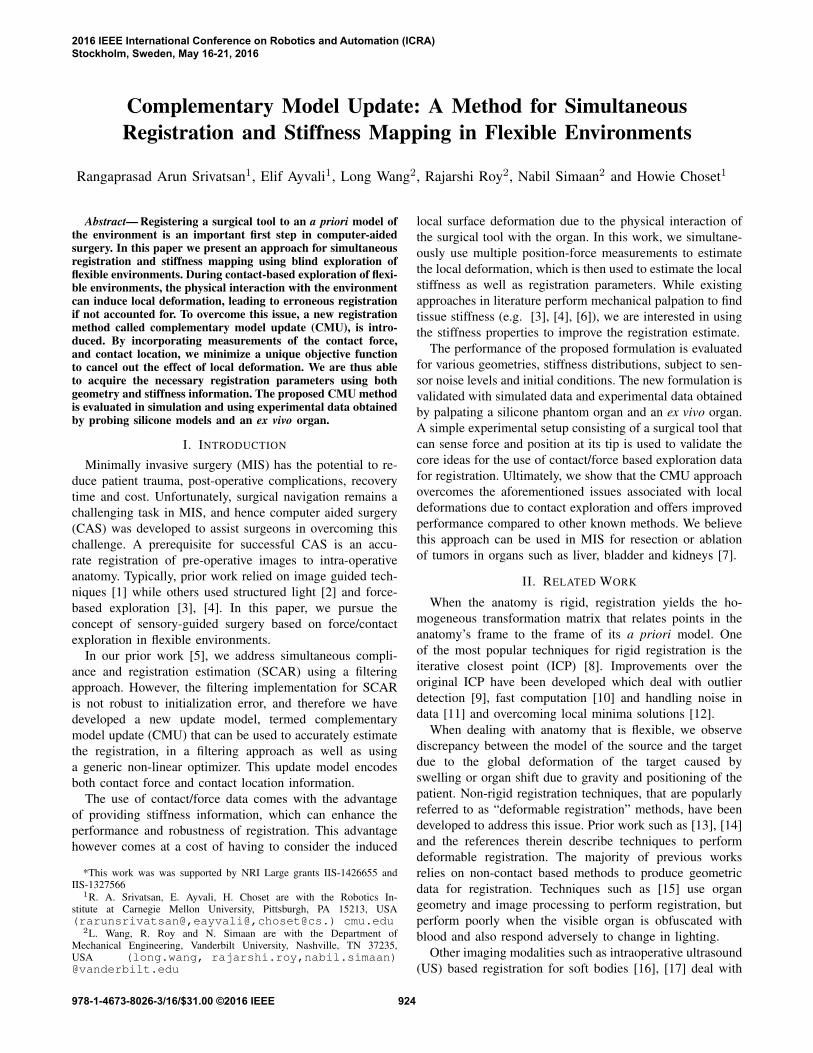
Fig. 1. Schematic shows ambiguity in single measurement based update
Fig. 1 shows the true location of the deformed point d∗pC1
which is at a depth d∗ along the normal nC1 . Let the locationof the deformed point obtained from the registration estimateof previous iteration be d
k−1pC1 as shown in Fig. 1. The
subscript k−1 indicates that the coordinates are transformedusing the registration estimate from the previous iteration.After applying the state update using Eq. 1, the updatedposition of the deformed point is d
kpC1 , which is at a depth
d along the normal (see Fig. 1). The filter estimates thestiffness value to be ci =
fjd 6=
fjd∗ = c∗i . As can be observed
from Eq. 1, substituting ci and dkp
C1 yields h1(xk) = 0.
Substituting c∗i and d∗
kpC1 in Eq. 1 also yields h1(xk) = 0.
1We assume that the tool is rigidly attached to the robot and hencetransformation between the robot’s frame and the tool’s frame can be carriedout trivially by a precomputed rigid transformation.
925
This results in an ambiguity in registration along the normaland an incorrect stiffness estimation.
We make an observation that when the registration isupdated based on a pair of observations, the ambiguity inregistration is resolved. Let us select two points, upC1 andupC2 , on the undeformed surface of the organ that arespatially close to each other. Since the points are close toeach other, we assume that the normals nC and the stiffnessc at both locations are the same. Let us apply a force ofmagnitude f1 and f2 respectively at upC1 and upC2 . Uponapplication of the force, the surface would deform by depths:
di =fic, i = 1, 2. (3)
From Eq. 3, we have:
c =f2 − f1d2 − d1
, when d2 6= d1. (4)
Let the coordinates of the deformed points be dpR1 and dpR2 .From Eq, 4, stiffness c = f2−f1
||dpR2 −dpR1 ||. We can now relate
the deformed and undeformed probed points from the linearstiffness model (see Fig. 1):
upC1 − nCd1 =d pC1
⇒upC1 − nCf1c
= T (dpR1 ), (5)
where T (p) transforms p from tool-frame to CAD model-frame. The LHS of Eq. 5 is the estimated position of thedeformed point in the CAD model frame based on theestimated stiffness c and the RHS is the coordinates ofthe sensed deformed points transformed to the CAD modelframe.
Based on Eq. 5, we can form a new objective function forobtaining the best registration as follows:
h2(T ) =
m∑j=1
∥∥∥∥∥upCj − nCj (fβ)jcj− T ((dpRβ )j)
∥∥∥∥∥2
, (6)
where (fβ)j and (dpRβ )j are the force and position measure-ments obtained by palpating the jth undeformed points andm is the total number of underformed points being probed.β ∈ {1, 2, ..., l} (l ≥ 2) is the index of the measurementtaken from the set of measurements at the jth undeformedpoint.
The stiffness cj is estimated from a pair of force-positionmeasurements obtained by probing the undeformed pointupCj . The stiffness is estimated first from a pair of force-position measurements and then used to optimize h2(T ).The objective function h2(T ) is the difference in the squarednorm of the distance between the estimated location of thedeformed point and the sensed location of the deformedpoint.
It is to be noted from Eq. 6 that h2(T ) only updates theregistration and Eq. 4 updates the stiffness, unlike h1(xk)that is used to update both stiffness and registration (seeEq. 1). This results in an accurate stiffness estimate elimi-nating the issue of ambiguous registration estimate that weobserve in [5].
If there are more than a pair of palpation points at theundeformed point upCj , then we have the following:
c =fkdk, k = 1, 2, ...l (l ≥ 2)
⇒c = fi − fjdi − dj
, i, j ∈ {1, 2, ..., l} and i 6= j. (7)
From Eq. 7, stiffness c linearly relates the depth (di −dj) to the applied force (fi − fj). Thus we havec = L(di − dj , fi − fj), where L is the function that returnsthe slope of the best line fit through a regression on the data{(di − dj), (fi − fj)}.
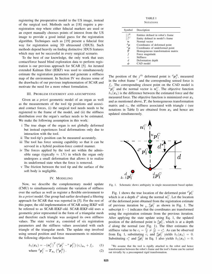
Fig. 2 shows a flowchart that provides an overview of thevarious steps described so far.
𝒅𝒑𝟏𝑹
𝒅𝒑𝟒𝑹
𝒅𝒑𝟐𝑹
𝒅𝒑𝟑𝑹
𝒅𝒑𝟓𝑹
Robot {R} Stiff features
Model {C}
CAD model
Palpation
T ϵ SE(3) Stiffness map
Complementary Model Update
(a)
(b)
(c)
(d)
(e) (f)
(g) Registration guess
dp1R,f1
dp2R,f2 dp3
R,f3 dp4R,f4 dp5
R,f5 …
Fig. 2. Flowchart describing the inputs and outputs for complementarymodel update (a) Flexible environment with embedded stiff features isprobed by a robot (b) Location of probed points are sensed (c) Compatibleforce-position measurements are collected (d) complementary model updateestimates the registration and stiffness map (e) Robot frame and model frameare registered (f) Stiffness map is generated (g) Prior geometric model andthe initial registration guess
The various steps involved in the CMU are listed below:1) Collection: In the collection step, pairs of force-position
measurements which satisfy the following conditionsare grouped together in the same set:
i The force magnitudes are different.ii The direction of normals fall within a threshold of
each other.iii The position measurements fall within a threshold
of each other.The three conditions stated above imply thatposition measurements correspond to the sameundeformed point being probed with differentforces, and forming a compatible set. Giventhe measurements (dpRi , fi), i = 1, 2, ..., nobtained so far, we collect compatible sets,
926
{((dpR1 )j , (f1)j), ((dpR2 )j , (f2)j), ...}, j = 1, 2, ...,m,where m is the total number of distinct sets obtained.
2) Stiffness estimation: For each of the compatible sets thathave at least one pair of force-position measurements,we estimate the local stiffness assuming a linear stiff-ness model as shown in Eq. 7.
3) Correspondence: The points (dpRβ )j are transformedusing the best registration estimate available to obtain(dpCβ )j . We then find,
(upCj ,n
Cj
)= M
((dpCβ )j ,φ
),
where M is the rule that finds the closest point upCj ∈ φto (dpβ)
Cj and the corresponding normal nCj . Other
alternates for M include methods such as [20], [21].4) Minimization: The objective function described in Eq. 6
is minimized using a least squares solver [22], [23] orcan be used in the update step of a Kalman filter [11]to estimate the registration.
5) We loop between the Correspondence and Minimiza-tion step until convergence or upto a fixed number ofiterations, upon obtaining T .
In the rest of this paper, we present results from an im-plementation of CMU that uses [23] for minimization; andwe refer to such an implementation as SCAR-LSQ-CMU.We have also implemented a filtering approach using CMU,which will be referred to as SCAR-IEKF-CMU. But wedo not present results of SCAR-IEKF-CMU due to spaceconstraints.
The minimization step would only return a local minimawhen using a filter or least squares solver. One way to findglobal minima is to use a branch and bound technique asdescribed in [12].
Algorithm 1: Complementary Model UpdateInput:dpRi ∈ R
3, i = 1, 2, ..., nfi ∈ R, i = 1, 2, ..., nA priori CAD model: φInitial transformation: T 0 ∈ SE(3)Output: Transformation T that aligns dpRi with φ
1 Collection: Collect points satisfying compatibilitycriteria: {
((dpR1 )j , (f1)j
),((dpR2 )j , (f2)j
), ...}
2 Stiffness estimation: Estimate the linear stiffness
cj = L(∥∥∥(dpRβ )j − (dpRγ )j
∥∥∥ , ((fβ)j − (fγ)j))
Optimize Initialize: T ← T 0
3 while not converged do4 Correspondence:
(upCj ,n
Cj
)=M
(T (dpRβ )j ,φ
)5 Minimization:
T = argminT
m∑j=1
∥∥∥∥upCj − nCj (fβ)jcj
− T (dpRβ )j∥∥∥∥2
V. SIMULATION STUDY
A. Comparison of SCAR-LSQ-CMU with SCAR-IEKF-old
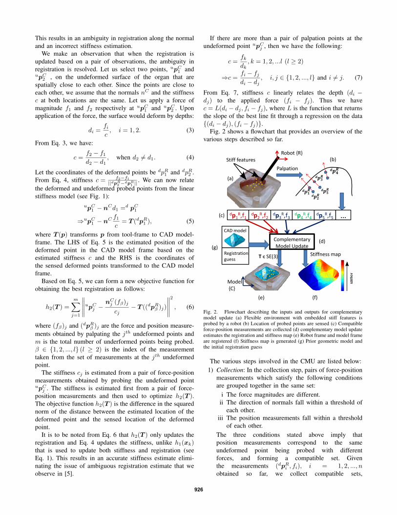
In Fig. 3 we compare the results of SCAR-LSQ-CMU withSCAR-IEKF-old for a simulated case of a pyramid shaped
organ with an embedded stiff feature that was probed at 250uniformly spaced points. The CAD model of the organ isrepresented in the form of a triangular mesh with 524 faces.We choose an initial guess for registration which is displacedalong the Z direction by 4mm.
SCAR-LSQ-CMU accurately estimates the trueregistration after palpation of about 20 points. WhileSCAR-IEKF-old correctly estimates the translationcomponents of registration (albeit not better thanSCAR-LSQ-CMU), there is significant rotational erroreven after probing 250 points (see Table II).
TABLE IIREGISTRATION COMPARISON
x y z θx θy θz RMS(mm) (mm) (mm) (deg) (deg) (deg) (mm)
Actual 0 0 0 0 0 0 –SCAR-LSQ-CMU 0 0 0 0 0 0 0SCAR-IEKF-old 0.32 0.12 2.46 -4.45 -1.03 1.22 5.66
The estimated stiffness map from SCAR-LSQ-CMU (seeFig. 3(b)) looks very similar to the ground truth stiff-ness map (see Fig. 3(a)), unlike the stiffness map esti-mated by SCAR-IEKF-old (see Fig. 3(c)). This exampledemonstrates how the CMU overcomes the ambiguity de-scribed in section IV and provides better estimates comparedto SCAR-IEKF-old.
(a) (b) (c)
Fig. 3. Stiffness in N/mm (a) Ground truth (b) Estimated bySCAR-LSQ-CMU (c) Estimated by SCAR-IEKF-old
B. Evaluation with different levels of sensor noise
In order to test the robustness of the proposed algorithmto the presence of noise in the sensor measurements, wedevelop simulation data in which we artificially add noiseto the measurements. We take the case of an organ whoseshape is as shown in Fig. 6(a) with a synthetic ground truthstiffness map as shown in Fig. 4(a). The CAD model has1311 triangle faces and is probed at 341 uniformly spacedpoints. At each palpated point, we record 10 measurementsby probing along the normal up to a depth of 3mm inincrements of 0.3mm. An artificial noise selected uniformlyfrom [0, 0.1]mm and [0, 0.1]N is added to the sensed positionand force respectively. Fig. 4(b) shows the stiffness map asestimated using SCAR-LSQ-CMU on this data. The stiffnessmap reveals the stiff features present in the ground truth. Fol-lowing this we increase the noise in the sensed position, by
927

selecting uniformly from [0, 0.3]mm. The stiffness estimationas shown in Fig. 4(c) demonstrates that SCAR-LSQ-CMUcan reveal the stiff features even in the presence of highsensor noise.
(a) (b) (c)
Fig. 4. Stiffness in N/mm(a) Ground truth (b) Estimated under low sensornoise (c) Estimated under high sensor noise
TABLE IIIREGISTRATION RESULTS FOR DIFFERENT NOISE LEVELS
x y z θx θy θz RMSLow noise level (mm) (mm) (mm) (deg) (deg) (deg) (mm)
Actual 7 -12 15 -11.46 5.72 8.59 –SCAR-LSQ-CMU 6.99 -11.94 14.99 -11.46 5.73 8.56 0.02ICP 6.40 -11.32 17.39 -11.28 5.35 8.36 2.33DICP 8.69 -13.63 17.12 -11.22 5.89 8.53 3.00
High noise level
SCAR-LSQ-CMU 6.99 -11.96 15.00 -11.48 5.72 8.56 0.02ICP 7.15 -13.14 17.14 -11.44 5.80 9.06 2.35DICP 8.59 -14.05 17.42 -11.30 5.94 8.87 3.24
Table III shows the comparison of the results as esti-mated by SCAR-LSQ-CMU with ICP [8], one of the mostpopular registration methods. Since ICP does not considerlocal deformations in its formulation, we create a modi-fied formulation of the ICP to compensate for the localdeformations (which we term deformation compensated ICPor DICP), so that we can provide a fair comparison toSCAR-LSQ-CMU. In DICP we estimate the local deforma-tion from the stiffness data and then displace the probedpoints along the sensed normal by the deformation depthto estimate the undeformed points. Upon estimating theundeformed points, we use the original ICP to estimate theregistration. In addition to finding the registration estimates,we also find the root mean square (RMS) error between theestimated positions and true positions, over all the probedpoints.
We assume the initial registration guess is T 0 = I , whereI is an identity matrix. As expected, estimating local defor-mations results in SCAR-LSQ-CMU performing better thanICP and DICP in both the cases. DICP is affected by noise insensed normal data resulting in a poor registration estimate,while SCAR-LSQ-CMU uses normal from the CAD model.
C. Exploration of robustness to initial registration error
For the simulated example presented in Section V-B withlower sensor noise, we evaluate the registration estimates fortwo different initial registration errors. The initial registration
error for Case 1 is lower than that for Case 2. From Table IVwe observe than SCAR-LSQ-CMU estimates registrationaccurately even in the presence of high initial registrationerror.
TABLE IVEXPLORATION OF ROBUSTNESS TO INITIAL CONDITIONS
x y z θx θy θz RMSCase1 (mm) (mm) (mm) (deg) (deg) (deg) (mm)
Initial 7.30 -12.10 15.61 -10.91 5.25 8.39 –Actual 7 -12 15 -11.46 5.72 8.59 –SCAR-LSQ-CMU 6.95 -11.94 14.99 -11.45 5.68 8.56 0.03ICP 7.07 -12.25 16.26 -11.40 5.79 8.73 1.31DICP 7.69 -11.86 16.21 -11.32 5.89 8.42 1.22
Case 2
Initial -13.31 -2.42 32.18 -30.76 -9.74 36.98 –SCAR-LSQ-CMU 6.97 -11.91 15.01 -11.47 5.70 8.54 0.02ICP 7.07 -12.25 16.26 -11.40 5.79 8.73 1.31DICP 8.93 -11.93 16.51 -14.93 6.05 8.66 3.67
VI. EXPERIMENTAL VALIDATION
A. Experimental Setup
𝒛
𝒙
𝒚
Ex-vivo organ
𝐱𝐸𝐸 𝐧
Silicone phantom
𝐱𝑐𝑜𝑛𝑡
(a)
(b)
Fig. 5. (a) Cartesian robot setup for experiments (b) Contact location andsurface norm estimation
To evaluate our CMU algorithm we have used a customdesigned Cartesian robot with an open architecture controller(see Fig. 5(a)). The robot end-effector was equipped withan ATI Nano43 F/T sensor. A target machine using MatlabSimulink R© Real-Time operating system was used for thelow level control at a control frequency of 1 KHz. For theprobing and environment exploration, a hybrid motion/forcecontroller was implemented as in Khatib [24] . The motioncontrol was accomplished using proportional derivative in-verse dynamics controller with a 5th order polynomial trajec-tory generator. A proportional integral control law was usedfor force control. The force and motion reference commandswere generated on a host machine which communicated withthe low-level target machine using UDP.
B. Robot Automatic Probing Procedures
Given a target region for exploration, the host machinegenerates a uniformly distributed grid map (uniform spacing
928
in the x−y plane of the robot) for probing locations. Given aparticular reference probing location xp, the robot repeats thefollowing steps to obtain the force-position measurements:
1) Making high force contact: The robot is first com-manded to move to a desired position xp and then tomove along the Z direction until a force magnitude 0.5Nis reached.
2) Estimating surface norm: The surface normal n is com-puted as the direction of the sensed force: n = fs/‖fs‖.The location of the contact point on the surface can becomputed as: xcont = xEE − nr (see Fig. 5(b)).
3) Finding low force surface contact point: The robotfirst retrieves swiftly away from the surface along thedirection of the estimated normal and then moves slowlytowards the surface along the normal till the sensedforce reaches a threshold.
4) Probing and recording: The force and position measure-ments are recorded as the robot moves up to a presetdepth into the organ under position control.
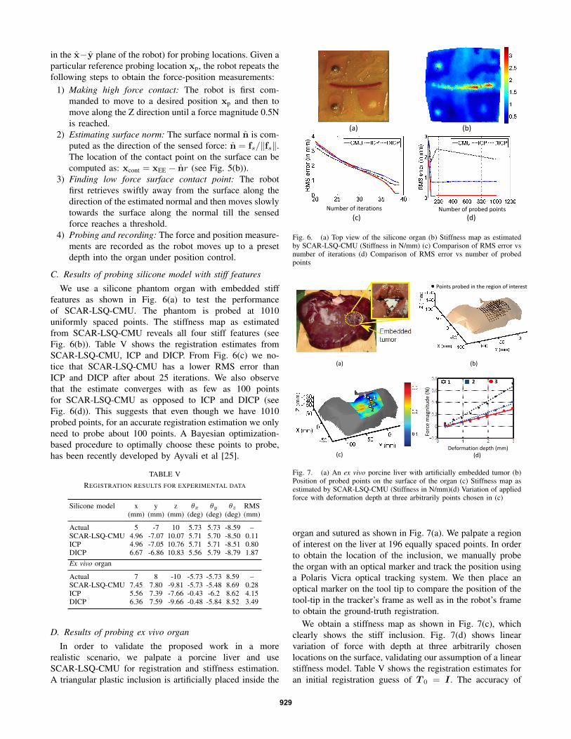
C. Results of probing silicone model with stiff features
We use a silicone phantom organ with embedded stifffeatures as shown in Fig. 6(a) to test the performanceof SCAR-LSQ-CMU. The phantom is probed at 1010uniformly spaced points. The stiffness map as estimatedfrom SCAR-LSQ-CMU reveals all four stiff features (seeFig. 6(b)). Table V shows the registration estimates fromSCAR-LSQ-CMU, ICP and DICP. From Fig. 6(c) we no-tice that SCAR-LSQ-CMU has a lower RMS error thanICP and DICP after about 25 iterations. We also observethat the estimate converges with as few as 100 pointsfor SCAR-LSQ-CMU as opposed to ICP and DICP (seeFig. 6(d)). This suggests that even though we have 1010probed points, for an accurate registration estimation we onlyneed to probe about 100 points. A Bayesian optimization-based procedure to optimally choose these points to probe,has been recently developed by Ayvali et al [25].
TABLE VREGISTRATION RESULTS FOR EXPERIMENTAL DATA
Silicone model x y z θx θy θz RMS(mm) (mm) (mm) (deg) (deg) (deg) (mm)
Actual 5 -7 10 5.73 5.73 -8.59 –SCAR-LSQ-CMU 4.96 -7.07 10.07 5.71 5.70 -8.50 0.11ICP 4.96 -7.05 10.76 5.71 5.71 -8.51 0.80DICP 6.67 -6.86 10.83 5.56 5.79 -8.79 1.87Ex vivo organ
Actual 7 8 -10 -5.73 -5.73 8.59 –SCAR-LSQ-CMU 7.45 7.80 -9.81 -5.73 -5.48 8.69 0.28ICP 5.56 7.39 -7.66 -0.43 -6.2 8.62 4.15DICP 6.36 7.59 -9.66 -0.48 -5.84 8.52 3.49
D. Results of probing ex vivo organ
In order to validate the proposed work in a morerealistic scenario, we palpate a porcine liver and useSCAR-LSQ-CMU for registration and stiffness estimation.A triangular plastic inclusion is artificially placed inside the
Number of probed points Number of iterations
(a) (b)
(c) (d)
Fig. 6. (a) Top view of the silicone organ (b) Stiffness map as estimatedby SCAR-LSQ-CMU (Stiffness in N/mm) (c) Comparison of RMS error vsnumber of iterations (d) Comparison of RMS error vs number of probedpoints
(a)
Points probed in the region of interest
(b)
1 2 3
(d) Deformation depth (mm)
Forc
e m
agn
itu
de
(N)
2
1 3
(c)
Fig. 7. (a) An ex vivo porcine liver with artificially embedded tumor (b)Position of probed points on the surface of the organ (c) Stiffness map asestimated by SCAR-LSQ-CMU (Stiffness in N/mm)(d) Variation of appliedforce with deformation depth at three arbitrarily points chosen in (c)
organ and sutured as shown in Fig. 7(a). We palpate a regionof interest on the liver at 196 equally spaced points. In orderto obtain the location of the inclusion, we manually probethe organ with an optical marker and track the position usinga Polaris Vicra optical tracking system. We then place anoptical marker on the tool tip to compare the position of thetool-tip in the tracker’s frame as well as in the robot’s frameto obtain the ground-truth registration.
We obtain a stiffness map as shown in Fig. 7(c), whichclearly shows the stiff inclusion. Fig. 7(d) shows linearvariation of force with depth at three arbitrarily chosenlocations on the surface, validating our assumption of a linearstiffness model. Table V shows the registration estimates foran initial registration guess of T 0 = I . The accuracy of
929
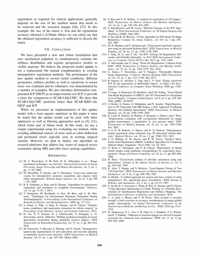
registration as required for clinical applications generallydepends on the size of the smallest tumor that needs tobe removed and the resection margin [26], [27]. In thisexample, the size of the tumor is 2cm and the registrationaccuracy obtained is 0.28mm. Hence we can safely say thatthe obtained registration accuracy is sufficient to discern thetumor.
VII. CONCLUSION
We have presented a new and robust formulation thatuses mechanical palpation to simultaneously estimate thestiffness distribution and register preoperative models tovisible anatomy. We believe the proposed model update isnot a replacement but instead complementary to existingintraoperative registration methods. The performance of thenew update method to several initial conditions, differentgeometries, stiffness profiles as well as sensitivity to sensornoise was evaluated and its robustness was demonstrated bya number of examples. We also introduce deformation com-pensated ICP (DICP) as an improvement over ICP, to providea more fair comparison to SCAR-LSQ-CMU. We show thatSCAR-LSQ-CMU performs better than SCAR-IEKF-old,DICP and ICP.
While we presented an implementation of this updatemodel with a least squares optimizer in this paper it mustbe noted that the update model can be used with otheroptimizers as well as filtering approaches such as [5], [11],which forms part of future work. In this work, we use asimple experimental setup for evaluating our method, whileavoiding additional sources of error such as robot deflectionand positional errors typically seen in existing surgicalsystems. However, we plan to deploy our algorithm onresearch platforms that address key issues of surgical accessconstraints during MIS and offer force sensing capabilities.
REFERENCES
[1] M. V. Wyawahare, P. M. Patil, H. K. Abhyankar, et al., “Imageregistration techniques: an overview,” International Journal of SignalProcessing, Image Processing and Pattern Recognition, vol. 2, no. 3,pp. 11–28, 2009.
[2] M. Hayashibe, N. Suzuki, and Y. Nakamura, “Laser-scan endoscopesystem for intraoperative geometry acquisition and surgical robotsafety management,” Medical Image Analysis, vol. 10, no. 4, pp. 509– 519, 2006.
[3] R. E. Goldman, A. Bajo, and N. Simaan, “Algorithms for autonomousexploration and estimation in compliant environments,” Robotica,vol. 31, pp. 71–87, 1 2013.
[4] T. Yamamoto, M. Bernhardt, A. Peer, M. Buss, and A. M. Oka-mura, “Techniques for Environment Parameter Estimation DuringTelemanipulation,” in Proceedings of the International Conference onBiomedical Robotics and Biomechatronics, 2008, pp. 217–223.
[5] S. Sanan, S. Tully, A. Bajo, N. Simaan, and H. Choset, “Simulta-neous compliance and registration estimation for robotic surgery,” inProceedings of the Robotics: Science and Systems Conference, 2014.
[6] H. Liu, D. P. Noonan, B. J. Challacombe, P. Dasgupta, L. D.Seneviratne, and K. Althoefer, “Rolling mechanical imaging for tissueabnormality localization during minimally invasive surgery,” IEEETransactions on Biomedical Engineering, vol. 57, no. 2, pp. 404–414,2010.
[7] M. Feuerstein, T. Mussack, S. Heining, and N. Navab, “Intraoperativelaparoscope augmentation for port placement and resection planningin minimally invasive liver resection,” IEEE Transactions on MedicalImaging, vol. 27, no. 3, pp. 355–369, March 2008.
[8] P. Besl and N. D. McKay, “A method for registration of 3-D shapes,”IEEE Transactions on Pattern Analysis and Machine Intelligence,vol. 14, no. 2, pp. 239–256, Feb 1992.
[9] S. Rusinkiewicz and M. Levoy, “Efficient Variants of the ICP Algo-rithm,” in Third International Conference on 3D Digital Imaging andModeling (3DIM), June 2001.
[10] P. Yan and K. W. Bowyer, “A Fast Algorithm for ICP-based 3D ShapeBiometrics,” Comput. Vis. Image Underst., vol. 107, no. 3, pp. 195–202, 2007.
[11] M. H. Moghari and P. Abolmaesumi, “Point-based rigid-body registra-tion using an unscented Kalman filter,” IEEE Transactions on MedicalImaging, vol. 26, no. 12, pp. 1708–1728, 2007.
[12] J. Yang, H. Li, and Y. Jia, “Go-ICP: Solving 3D Registration Effi-ciently and Globally Optimally,” in 2013 IEEE International Confer-ence on Computer Vision (ICCV), Dec 2013, pp. 1457–1464.
[13] A. Myronenko and X. Song, “Point Set Registration: Coherent PointDrift,” IEEE Transactions on Pattern Analysis and Machine Intelli-gence, vol. 32, no. 12, pp. 2262–2275, Dec 2010.
[14] A. Sotiras, C. Davatzikos, and N. Paragios, “Deformable MedicalImage Registration: A Survey,” Medical Imaging, IEEE Transactionson, vol. 32, no. 7, pp. 1153–1190, July 2013.
[15] R. Sagawa, K. Akasaka, Y. Yagi, and L. V. Gool, “Elastic convolvedICP for the registration of deformable objects,” in IEEE 12th Inter-national Conference on Computer Vision Workshop, 2009, pp. 1558–1565.
[16] T. Lange, S. Eulenstein, M. Hnerbein, and P.-M. Schlag, “Vessel-BasedNon-Rigid Registration of MR/CT and 3D Ultrasound for Navigationin Liver Surgery,” Computer Aided Surgery, vol. 8, no. 5, pp. 228–240,2003, pMID: 15529952.
[17] A. Roche, X. Pennec, G. Malandain, and N. Ayache, “Rigid Registra-tion of 3D Ultrasound with MR Images: a New Approach CombiningIntensity and Gradient Information,” IEEE Transactions on MedicalImaging, vol. 20, pp. 1038–1049, 2001.
[18] K. Lunn, K. Paulsen, D. Roberts, F. Kennedy, A. Hartov, and J. West,“Displacement estimation with co-registered ultrasound for imageguided neurosurgery: a quantitative in vivo porcine study,” IEEETransactions on Medical Imaging, vol. 22, no. 11, pp. 1358–1368,Nov 2003.
[19] S. Ji, D. W. Roberts, A. Hartov, and K. D. Paulsen, “Intraoperativepatient registration using volumetric true 3D ultrasound without fidu-cials,” Medical Physics, vol. 39, no. 12, pp. 7540–7552, 2012.
[20] S. D. Billings, E. M. Boctor, and R. H. Taylor, “Iterative Most-Likely Point Registration (IMLP): A Robust Algorithm for ComputingOptimal Shape Alignment,” PLoS ONE, vol. 10, 2015.
[21] N. Ryan, C. Heneghan, and P. de Chazal, “Registration of digitalretinal images using landmark correspondence by expectation maxi-mization,” Image and Vision Computing, vol. 22, no. 11, pp. 883–898,2004.
[22] B. Horn, “Closed-form solution of absolute orientation using unitquaternions,” Journal of the Optical Society of America A, vol. 4,pp. 629–642, 1987.
[23] K. Arun, T. Huang, and S. Bolstein, “Least-Squares Fitting of Two3-D Point Sets,” IEEE Transactions on Pattern Analysis and MachineIntelligence, vol. 9, no. 5, pp. 698–700, 1987.
[24] O. Khatib, “A unified approach for motion and force control of robotmanipulators: The operational space formulation,” IEEE Journal ofRobotics and Automation, vol. 3, no. 1, pp. 43–53, 1987.
[25] E. Ayvali, R. A. Srivatsan, L. Wang, R. Roy, N. Simaan, and H. Choset,“Using Bayesian Optimization to Guide Probing of a Flexible Envi-ronment for Simultaneous Registration and Stiffness Mapping,” TheInternational Conference on Robotics and Automation, 2016.
[26] C. A. Linte, J. Moore, and T. M. Peters, “How accurate is accurateenough? a brief overview on accuracy considerations in image-guidedcardiac interventions,” in Annual International Conference of theEngineering in Medicine and Biology Society. IEEE, 2010, pp. 2313–2316.
[27] D. Vandeweyer, E. L. Neo, J. W. Chen, G. J. Maddern, T. G. Wilson,and R. T. Padbury, “Influence of resection margin on survival in hepaticresections for colorectal liver metastases,” HPB, vol. 11, no. 6, pp.499–504, 2009.
930