complete installation & programming guide t elematics … · 2019-02-28 · once the telematics...
TRANSCRIPT

EN-20200128-A
This system must be installed by a professional.
NOTICEThe manufacturer will accept no responsability for any electrical damage resulting fromimproper installation of this product, be that either damage to the vehicle itself or to theinstalled device. This device must be installed by a certified technician. Please review theInstallation Guide carefully before beginning any work.
COMPLETE INSTALLATION & PROGRAMMING GUIDE Telematics Communicator System

HARDWARE PARTS ................................................................................................................................ 3
iDATASTART HCx .....................................................................................................................................4
iDATASTART VWx .................................................................................................................................... 6
iDATASTART BM or BZ .......................................................................................................................... 8
AKX or OEM ............................................................................................................................................. 10
ADS-AL-CA / OL-MDB-ALL ................................................................................................................12
CRIMESTOPPER ......................................................................................................................................14
FLASHLOGIC FL-CAN ...........................................................................................................................16
FLASHLOGIC FLRS ................................................................................................................................18
FLASHLOGIC FLRSBA ........................................................................................................................ 20
FLASHLOGIC FLCMVW .......................................................................................................................22
COMPUSTAR CM7000 / CM7200 / POLARSTART PRS-16 ...................................................24
COMPUSTAR CM6200 .........................................................................................................................26
COMPUSTAR DC2 ..................................................................................................................................28
COMPUSTAR DC3 ................................................................................................................................. 30
POLARSTART PRS-13 ...........................................................................................................................32
DIRECTED DBALL 2 ..............................................................................................................................34
DIRECTED DB3 .......................................................................................................................................36
DIRECTED 4X10 - 5X10 - AF-D600 - ASD200 - ASD-600 ....................................................38
DIRECTED DS4 - DS4+ ....................................................................................................................... 40
FORTIN EVO-ALL ..................................................................................................................................42
FORTIN EVO-ONE ................................................................................................................................ 44
PRESTIGE (E) Models .......................................................................................................................... 46
PRESTIGE (Z) Models .......................................................................................................................... 48
PURSUIT (E) Models ............................................................................................................................ 50
CODE SYSTEMS ......................................................................................................................................52
OLDER CODE SYSTEMS......................................................................................................................54
OMEGA RS-X70 ......................................................................................................................................56
OMEGA AL-XX70-B ..............................................................................................................................58
OMEGA OLRS ......................................................................................................................................... 60
MIDCITY SMARTKEY STARTER ........................................................................................................62
DSE 503AIR 5R-85 ............................................................................................................................... 64
DSE iSTART2 - 3 .................................................................................................................................... 66
LED Status Reference Chart ..............................................................................................................68
RESET PROCEDURE .............................................................................................................................68
2
TABLE OF CONTENTS

HRN-MCAR-01
HRN-LLRS-01
HRN-DRS-02
FLCL6HAR, OL-HRN-LINKR-ALL (Sold Separately)
OL-ADAPTER-B2GThis Adapter is supplied ONLY inside
the Linkr LT boxes.
OL-ADAPTER-B2G
HARDWARE PARTS
AR-3HU / VS-4LU
CREATE AN ACCOUNTBefore begining the installation and setting the configurations of a MyCar Controls unit, we strongly recommend downloading the Application from the App store and create a user account.
a. Go to the App store (Apple) or Play store (Android) and Search for “MYCAR CONTROLS”. Download and install the Free Application.b. Launch the newly installed MyCar Application on your smartphone or tabletc. Click “Create an Account”d. Fill in all the required fieldse. Once completed, click “Create your Account”f. Open your Email and look for a new email sent from “MYCARCONTROLS”g. To activate your account and create your secure password, click the embedded link in the email.h. Create your secure password and activate your account.i. Once done, Log into the Application using your email and your newly created password.

4
PARTS REQUIRED FOR INSTALLATION OF : iDATASTART HCxTelematics device HRN-MCAR-01 iDatastart HCx
STEP 1. CONFIGURE THE REMOTE STARTERThe ADS Weblink (ADS-USB) is required to properly configure the iDatastart HCx remote starter to accept the telematic device. When flashing the iDatastart HCx remote starter, please ensure to turn ON the Telematics option from the telematics section and choose “MyCar”.
STEP 2. CONNECT
3
(+) HORN (PULSE) OR
(+) SIREN (CONSTANT)ANALOG INPUT SIGNAL FOR ALARM DETECTION
(+) 12V BATTERY (1)
GROUND (1)
+12
V B
atte
ry (RED)
Gro
und
(BLA
CK)
Dat
a (W
HITE)
Dat
a (B
LUE)
Ala
rm(+
) (YELL
OW
)
Installation: Place module 3 inches (minimum) from any metal surface
Orientation: Horizontal; small door facing upward (as seen in this diagram)
(1) Connect only when remote starter is not supplying power to telematics device
INSTALLATION, WIRING & PROGRAMMING GUIDE

STEP 3. NETWORK CONNECTIVITYOnce the telematics module is connected into the remote starter, two LED’s will display to which networks you are connected to. (See LED Status Reference Chart on last page for details). NOTE: The vehicle may need to be outside in an open area in order to connect to a cellular and/or GPS network.
STEP 4. ADD A DEVICE/VEHICLE TO AN ACCOUNTa. Click the “+” sign at the bottom right of the Application screen. This will allow you to temporarily add
your customers device/vehicle to your personal account.b. Enter the 16 digit “Serial Number” found at the back of the telematic device
(SN: XXXXXX-XXXXXXXXXX) and Click “Submit the code”.c. You are now in “Test Mode”. Test Mode will allow you up to 4 hours for you to test the newly
installed device. At any time during this 4 hour period, you can exit testing mode and make unit “Ready for Customer Delivery” by “Releasing the vehicle” or by “Transfering the vehicle” from your account. NOTE: If you do NOT remove the vehicle from your account, it will automatically be removed from your account and make the unit “Ready for Customer Delivery”.
STEP 5. PRE-CONFIGURE MYCAR APPLICATION EXPERIENCE FOR YOUR CUSTOMERa. Click on the newly added vehicle from the vehicle list to enter the control screen (the screen that will al-
low you to control the vehicle’s remote start functions). This will automatically take you to the “Vehicle Configuration” page for this vehicle. You will be prompt to “Set a Bypass Protocol” to use this device. Click “Ok”.
b. Now you must set the protocol for the telematic device. When combined with the iDatastart HCx remote starter previously installed, you must set the protocol to “ADS” and click “ACCEPT” then click “Done” at the top right corner.
c. Now please allow a moment (About 5 minutes) for the telematic device to update your protocol selec-tion and reboot. After this wait period it will be available to accept commands from the App. In the vehicle control screen, the Device Signal icon located above the Stop button will display the connectiv-ity status of your telematic device. If the icon is Grayed out, Please wait, Device is still Offline. If icon is Green, Device is Online and Ready to go.
d. Then from the top right click on of the Settings section edit the Vehicle name, configure the Auxiliaries that might have been added if applicable and click ACCEPT when done. Then choose the vehicle to display inside the control panel in the VEHICLE IMAGE section and click ACCEPT once done.
e. When your configurations are all completed, click “Done” at the top right corner. All Configurations will take effect.
STEP 6. TEST YOUR DEVICEWhen the system is Online you start testing the unit from the vehicle control panel. Test all the application functions (Start, Stop, Lock, Unlock, Auxiliaries, ETC.) When done with the testing, from the vehicle list you can “Release” the vehicle. There are 2x different method to release it to the new owner. Choosing “release” will simply remove it from your account and make it “Ready for Customer Delivery”. Choosing “transfer” will transfer the device to the new owner’s account.
Also make sure that the Owners Card is handed to the New Owner of the vehicle. Doing this will ensure that the instructions on how to setup their App, Account and Vehicle is done correctly by using the device serial number located on the sticker affixed by the installer at the time of installation.
INSTALLATION, WIRING & PROGRAMMING GUIDE

6
PARTS REQUIRED FOR INSTALLATION OF : iDATASTART VWxTelematics device HRN-MCAR-01 iDatastart VWx
STEP 1. CONFIGURE THE REMOTE STARTERThe ADS Weblink (ADS-USB) is required to properly configure the iDatastart VWx remote starter to accept the telematic device. When flashing the iDatastart VWx remote starter, please ensure to turn ON the Telematics option from the telematics section and choose “MyCar”.
STEP 2. CONNECT3
(+) HORN (PULSE) OR
(+) SIREN (CONSTANT)ANALOG INPUT SIGNAL FOR ALARM DETECTION
(+) 12V BATTERY (1)
GROUND (1)
+12
V B
atte
ry (RED)
Gro
und
(BLA
CK)
Dat
a (W
HITE)
Dat
a (B
LUE)
Ala
rm(+
) (YELL
OW
)
Installation: Place module 3 inches (minimum) from any metal surface
Orientation: Horizontal; small door facing upward (as seen in this diagram)
(1) Connect only when remote starter is not supplying power to telematics device
INSTALLATION, WIRING & PROGRAMMING GUIDE

STEP 3. NETWORK CONNECTIVITYOnce the telematics module is connected into the remote starter, two LED’s will display to which networks you are connected to. (See LED Status Reference Chart on last page for details). NOTE: The vehicle may need to be outside in an open area in order to connect to a cellular and/or GPS network.
STEP 4. ADD A DEVICE/VEHICLE TO AN ACCOUNTa. Click the “+” sign at the bottom right of the Application screen. This will allow you to temporarily add
your customers device/vehicle to your personal account.b. Enter the 16 digit “Serial Number” found at the back of the telematic device
(SN: XXXXXX-XXXXXXXXXX) and Click “Submit the code”.c. You are now in “Test Mode”. Test Mode will allow you up to 4 hours for you to test the newly
installed device. At any time during this 4 hour period, you can exit testing mode and make unit “Ready for Customer Delivery” by “Releasing the vehicle” or by “Transfering the vehicle” from your account. NOTE: If you do NOT remove the vehicle from your account, it will automatically be removed from your account and make the unit “Ready for Customer Delivery”.
STEP 5. PRE-CONFIGURE MYCAR APPLICATION EXPERIENCE FOR YOUR CUSTOMERa. Click on the newly added vehicle from the vehicle list to enter the control screen (the screen that will al-
low you to control the vehicle’s remote start functions). This will automatically take you to the “Vehicle Configuration” page for this vehicle. You will be prompt to “Set a Bypass Protocol” to use this device. Click “Ok”.
b. Now you must set the protocol for the telematic device. When combined with the iDatastart VW remote starter previously installed, you must set the protocol to “ADS” and click “ACCEPT” then click “Done” at the top right corner.
c. Now please allow a moment (About 5 minutes) for the telematic device to update your protocol selec-tion and reboot. After this wait period it will be available to accept commands from the App. In the vehicle control screen, the Device Signal icon located above the Stop button will display the connectiv-ity status of your telematic device. If the icon is Grayed out, Please wait, Device is still Offline. If icon is Green, Device is Online and Ready to go.
d. Then from the top right click on of the Settings section edit the Vehicle name, configure the Auxiliaries that might have been added if applicable and click ACCEPT when done. Then choose the vehicle to display inside the control panel in the VEHICLE IMAGE section and click ACCEPT once done.
e. When your configurations are all completed, click “Done” at the top right corner. All Configurations will take effect.
STEP 6. TEST YOUR DEVICEWhen the system is Online you start testing the unit from the vehicle control panel. Test all the application functions (Start, Stop, Lock, Unlock, Auxiliaries, ETC.) When done with the testing, from the vehicle list you can “Release” the vehicle. There are 2x different method to release it to the new owner. Choosing “release” will simply remove it from your account and make it “Ready for Customer Delivery”. Choosing “transfer” will transfer the device to the new owner’s account.
Also make sure that the Owners Card is handed to the New Owner of the vehicle. Doing this will ensure that the instructions on how to setup their App, Account and Vehicle is done correctly by using the device serial number located on the sticker affixed by the installer at the time of installation.
INSTALLATION, WIRING & PROGRAMMING GUIDE

8
PARTS REQUIRED FOR INSTALLATION OF : iDATASTART BM or BZTelematics device HRN-MCAR-01 iDatastart BM or BZ
STEP 1. CONFIGURE THE REMOTE STARTERThe ADS Weblink (ADS-USB) is required to properly configure the iDatastart BM or BZ remote starter to accept the telematic device. When flashing the iDatastart BM or BZ remote starter, please ensure to choose the “MyCar” telematics protocol.
STEP 2. CONNECT
(1) Connect only when remote starter is not supplying power to telematics device
3
(+) HORN (PULSE) OR
(+) SIREN (CONSTANT)ANALOG INPUT SIGNAL FOR ALARM DETECTION
(+) 12V BATTERY (1)
GROUND (1)
+12
V B
atte
ry (RED)
Gro
und
(BLA
CK)
Dat
a (W
HITE)
Dat
a (B
LUE)
Ala
rm(+
) (YELL
OW
)
Installation: Place module 3 inches (minimum) from any metal surface
Orientation: Horizontal; small door facing upward (as seen in this diagram)
INSTALLATION, WIRING & PROGRAMMING GUIDE

STEP 3. NETWORK CONNECTIVITYOnce the telematics module is connected into the remote starter, two LED’s will display to which networks you are connected to. (See LED Status Reference Chart on last page for details). NOTE: The vehicle may need to be outside in an open area in order to connect to a cellular and/or GPS network.
STEP 4. ADD A DEVICE/VEHICLE TO AN ACCOUNTa. Click the “+” sign at the bottom right of the Application screen. This will allow you to temporarily add
your customers device/vehicle to your personal account.b. Enter the 16 digit “Serial Number” found at the back of the telematic device
(SN: XXXXXX-XXXXXXXXXX) and Click “Submit the code”.c. You are now in “Test Mode”. Test Mode will allow you up to 4 hours for you to test the newly
installed device. At any time during this 4 hour period, you can exit testing mode and make unit “Ready for Customer Delivery” by “Releasing the vehicle” or by “Transfering the vehicle” from your account. NOTE: If you do NOT remove the vehicle from your account, it will automatically be removed from your account and make the unit “Ready for Customer Delivery”.
STEP 5. PRE-CONFIGURE MYCAR APPLICATION EXPERIENCE FOR YOUR CUSTOMERa. Click on the newly added vehicle from the vehicle list to enter the control screen (the screen that will al-
low you to control the vehicle’s remote start functions). This will automatically take you to the “Vehicle Configuration” page for this vehicle. You will be prompt to “Set a Bypass Protocol” to use this device. Click “Ok”.
b. Now you must set the protocol for the telematic device. When combined with the iDatastart BM or BZ remote starter previously installed, you must set the protocol to “ADS” and click “ACCEPT” then click “Done” at the top right corner.
c. Now please allow a moment (About 5 minutes) for the telematic device to update your protocol selec-tion and reboot. After this wait period it will be available to accept commands from the App. In the vehicle control screen, the Device Signal icon located above the Stop button will display the connectiv-ity status of your telematic device. If the icon is Grayed out, Please wait, Device is still Offline. If icon is Green, Device is Online and Ready to go.
d. Then from the top right click on of the Settings section edit the Vehicle name, configure the Auxiliaries that might have been added if applicable and click ACCEPT when done. Then choose the vehicle to display inside the control panel in the VEHICLE IMAGE section and click ACCEPT once done.
e. When your configurations are all completed, click “Done” at the top right corner. All Configurations will take effect.
STEP 6. TEST YOUR DEVICEWhen the system is Online you start testing the unit from the vehicle control panel. Test all the application functions (Start, Stop, Lock, Unlock, Auxiliaries, ETC.) When done with the testing, from the vehicle list you can “Release” the vehicle. There are 2x different method to release it to the new owner. Choosing “release” will simply remove it from your account and make it “Ready for Customer Delivery”. Choosing “transfer” will transfer the device to the new owner’s account.
Also make sure that the Owners Card is handed to the New Owner of the vehicle. Doing this will ensure that the instructions on how to setup their App, Account and Vehicle is done correctly by using the device serial number located on the sticker affixed by the installer at the time of installation.
INSTALLATION, WIRING & PROGRAMMING GUIDE

10
PARTS REQUIRED FOR INSTALLATION OF : AKX or OEMTelematics device HRN-MCAR-01 AKX or OEM
STEP 1. CONFIGURE THE REMOTE STARTERThe ADS Weblink (ADS-USB) is required to properly configure the AKX or OEM remote starter to accept the telematic device. When flashing the AKX or OEM remote starter, please ensure to choose the “MyCar” telematics protocol.
STEP 2. CONNECT
(1) Connect only when remote starter is not supplying power to telematics device
3
(+) HORN (PULSE) OR
(+) SIREN (CONSTANT)ANALOG INPUT SIGNAL FOR ALARM DETECTION
(+) 12V BATTERY (1)
GROUND (1)
+12
V B
atte
ry (RED)
Gro
und
(BLA
CK)
Dat
a (W
HITE)
Dat
a (B
LUE)
Ala
rm(+
) (YELL
OW
)
Installation: Place module 3 inches (minimum) from any metal surface
Orientation: Horizontal; small door facing upward (as seen in this diagram)
INSTALLATION, WIRING & PROGRAMMING GUIDE

STEP 3. NETWORK CONNECTIVITYOnce the telematics module is connected into the remote starter, two LED’s will display to which networks you are connected to. (See LED Status Reference Chart on last page for details). NOTE: The vehicle may need to be outside in an open area in order to connect to a cellular and/or GPS network.
STEP 4. ADD A DEVICE/VEHICLE TO AN ACCOUNTa. Click the “+” sign at the bottom right of the Application screen. This will allow you to temporarily add
your customers device/vehicle to your personal account.b. Enter the 16 digit “Serial Number” found at the back of the telematic device
(SN: XXXXXX-XXXXXXXXXX) and Click “Submit the code”.c. You are now in “Test Mode”. Test Mode will allow you up to 4 hours for you to test the newly
installed device. At any time during this 4 hour period, you can exit testing mode and make unit “Ready for Customer Delivery” by “Releasing the vehicle” or by “Transfering the vehicle” from your account. NOTE: If you do NOT remove the vehicle from your account, it will automatically be removed from your account and make the unit “Ready for Customer Delivery”.
STEP 5. PRE-CONFIGURE MYCAR APPLICATION EXPERIENCE FOR YOUR CUSTOMERa. Click on the newly added vehicle from the vehicle list to enter the control screen (the screen that will al-
low you to control the vehicle’s remote start functions). This will automatically take you to the “Vehicle Configuration” page for this vehicle. You will be prompt to “Set a Bypass Protocol” to use this device. Click “Ok”.
b. Now you must set the protocol for the telematic device. When combined with the AKX or OEM remote starter previously installed, you must set the protocol to “ADS” and click “ACCEPT” then click “Done” at the top right corner.
c. Now please allow a moment (About 5 minutes) for the telematic device to update your protocol selec-tion and reboot. After this wait period it will be available to accept commands from the App. In the vehicle control screen, the Device Signal icon located above the Stop button will display the connectiv-ity status of your telematic device. If the icon is Grayed out, Please wait, Device is still Offline. If icon is Green, Device is Online and Ready to go.
d. Then from the top right click on of the Settings section edit the Vehicle name, configure the Auxiliaries that might have been added if applicable and click ACCEPT when done. Then choose the vehicle to display inside the control panel in the VEHICLE IMAGE section and click ACCEPT once done.
e. When your configurations are all completed, click “Done” at the top right corner. All Configurations will take effect.
STEP 6. TEST YOUR DEVICEWhen the system is Online you start testing the unit from the vehicle control panel. Test all the application functions (Start, Stop, Lock, Unlock, Auxiliaries, ETC.) When done with the testing, from the vehicle list you can “Release” the vehicle. There are 2x different method to release it to the new owner. Choosing “release” will simply remove it from your account and make it “Ready for Customer Delivery”. Choosing “transfer” will transfer the device to the new owner’s account.
Also make sure that the Owners Card is handed to the New Owner of the vehicle. Doing this will ensure that the instructions on how to setup their App, Account and Vehicle is done correctly by using the device serial number located on the sticker affixed by the installer at the time of installation.
INSTALLATION, WIRING & PROGRAMMING GUIDE

12
PARTS REQUIRED FOR INSTALLATION OF : ADS-AL-CA / OL-MDB-ALLTelematics device HRN-MCAR-01 ADS-AL-CA / OL-MDB-ALL FLCL6HAR,
OL-HRN-LINKR-ALL
(sold Separately)
STEP 1. CONFIGURE THE REMOTE STARTERThe ADS Weblink (ADS-USB) is required to properly configure the ADS-AL-CA or OL-MDB-ALL remote starter to accept the MyCar telematics device. When flashing the ADS-AL-CA or OL-MDB-ALL remote starter, please ensure to choose the “MyCar” telematics protocol.
STEP 2. CONNECT
(1) Connect only when remote starter is not supplying power to telematics device
3
(+) HORN (PULSE) OR
(+) SIREN (CONSTANT)ANALOG INPUT SIGNAL FOR ALARM DETECTION
(+) 12V BATTERY (1)
GROUND (1)
+12
V B
atte
ry (RED)
Gro
und
(BLA
CK)
Dat
a (W
HITE)
Dat
a (B
LUE)
Ala
rm(+
) (YELL
OW
)
Installation: Place module 3 inches (minimum) from any metal surface
Orientation: Horizontal; small door facing upward (as seen in this diagram)
FLCL
6HA
R
INSTALLATION, WIRING & PROGRAMMING GUIDE

STEP 3. NETWORK CONNECTIVITYOnce the telematics module is connected into the remote starter, two LED’s will display to which networks you are connected to. (See LED Status Reference Chart on last page for details). NOTE: The vehicle may need to be outside in an open area in order to connect to a cellular and/or GPS network.
STEP 4. ADD A DEVICE/VEHICLE TO AN ACCOUNTa. Click the “+” sign at the bottom right of the Application screen. This will allow you to temporarily add
your customers device/vehicle to your personal account.b. Enter the 16 digit “Serial Number” found at the back of the device (SN: XXXXXX-XXXXXXXXXX) and
Click “Submit the code”.c. You are now in “Test Mode”. Test Mode will allow you up to 4 hours for you to test the newly in-
stalled device. At any time during this 4 hour period, you can exit testing mode and make unit “Ready for Customer Delivery” by “Releasing the vehicle” or by “Transfering the vehicle” from your account. NOTE: If you do NOT remove the vehicle from your account, it will automatically be removed from your account and make the unit “Ready for Customer Delivery”.
STEP 5. PRE-CONFIGURE MYCAR APPLICATION EXPERIENCE FOR YOUR CUSTOMERa. Click on the newly added vehicle from the vehicle list to enter the control screen (the screen that will al-
low you to control the vehicle’s remote start functions). This will automatically take you to the “Vehicle Configuration” page for this vehicle. You will be prompt to “Set a Bypass Protocol” to use this device. Click “Ok”.
b. Now you must set the protocol for the MyCar device. When combined with the ADS-AL-CA or OL-MDB-ALL remote starter previously installed, you must set the protocol to “ADS” and click “ACCEPT” then click “Done” at the top right corner.
c. Now please allow a moment (About 5 minutes) for the MyCar device to update your protocol selection and reboot. After this wait period it will be available to accept commands from the App. In the vehicle control screen, the Device Signal icon located above the Stop button will display the connectivity status of your MyCar device. If the icon is Grayed out, Please wait, Device is still Offline. If icon is Green, Device is Online and Ready to go.
d. Then from the top right click on of the Settings section edit the Vehicle name, configure the Auxiliaries that might have been added if applicable and click ACCEPT when done. Then choose the vehicle to dis-play in the control panel in the VEHICLE IMAGE section and click ACCEPT once done.
e. When your configurations are all completed, click “Done” at the top right corner. All Configurations will take effect.
STEP 6. TEST YOUR DEVICEWhen the system is Online you start testing the unit from the vehicle control panel. Test all the application functions (Start, Stop, Lock, Unlock, Auxiliaries, ETC.) When done with the testing, from the vehicle list you can “Release” the vehicle. There are 2x different method to release it to the new owner. Choosing “release” will simply remove it from your account and make it “Ready for Customer Delivery”. Choosing “transfer” will transfer the device to the new owner’s account.
Also make sure that the MyCar Owners Card is handed to the New Owner of the vehicle. Doing this will ensure that the instructions on how to setup their App, Account and Vehicle is done correctly by using the device serial number located on the sticker affixed by the installer at the time of installation.
INSTALLATION, WIRING & PROGRAMMING GUIDE

14
PARTS REQUIRED FOR INSTALLATION OF : CRIMESTOPPERTelematics device HRN-MCAR-01 CrimeStopper HRN-LLRS-01
STEP 1. CONFIGURE THE REMOTE STARTERThe CrimeStopper remote starter must be configured to accept the telematics device. When programming the CrimeStopper remote starter, please ensure to select the option indicated “Smart Phone Baud Rate”. This option MUST BE SET TO 9600baud.
1- Disconnect the HRN-LLRS-01 white connector from Crimestopper Remote Starter2- Go in the Crimestopper programming and set Baud rate to 9600.3- Shut ignition Off and Disconnect Power from the Crimestopper RS.5- Wait 10 seconds. Then Reconnect RS and the HRN-LLRS-01 harness for the MyCar.
STEP 2. CONNECT
(1) Connect only when remote starter is not supplying power to telematics device
Compatible models: RS-00, RSx-G5, SP402, SP502
3
(+) HORN (PULSE) OR
(+) SIREN (CONSTANT)ANALOG INPUT SIGNAL FOR ALARM DETECTION
(+) 12V BATTERY (1)
GROUND (1)
+12
V B
atte
ry (RED)
Gro
und
(BLA
CK)
Dat
a (W
HITE)
Dat
a (B
LUE)
Ala
rm(+
) (YELL
OW
)
Installation: Place module 3 inches (minimum) from any metal surface
Orientation: Horizontal; small door facing upward (as seen in this diagram)
HRN-LLRS-01
INSTALLATION, WIRING & PROGRAMMING GUIDE

STEP 3. NETWORK CONNECTIVITYOnce the telematics module is connected into the remote starter, two LED’s will display to which networks you are connected to. (See LED Status Reference Chart on last page for details). NOTE: The vehicle may need to be outside in an open area in order to connect to a cellular and/or GPS network.
STEP 4. ADD A DEVICE/VEHICLE TO AN ACCOUNTa. Click the “+” sign at the bottom right of the Application screen. This will allow you to temporarily add
your customers device/vehicle to your personal account.b. Enter the 16 digit “Serial Number” found at the back of the telematic device
(SN: XXXXXX-XXXXXXXXXX) and Click “Submit the code”.c. You are now in “Test Mode”. Test Mode will allow you up to 4 hours for you to test the newly
installed device. At any time during this 4 hour period, you can exit testing mode and make unit “Ready for Customer Delivery” by “Releasing the vehicle” or by “Transfering the vehicle” from your account. NOTE: If you do NOT remove the vehicle from your account, it will automatically be removed from your account and make the unit “Ready for Customer Delivery”.
STEP 5. PRE-CONFIGURE MYCAR APPLICATION EXPERIENCE FOR YOUR CUSTOMERa. Click on the newly added vehicle from the vehicle list to enter the control screen (the screen that will al-
low you to control the vehicle’s remote start functions). This will automatically take you to the “Vehicle Configuration” page for this vehicle. You will be prompt to “Set a Bypass Protocol” to use this device. Click “Ok”.
b. Now you must set the protocol for the telematic device. When combined with the CrimeStopper remote starter previously installed, you must set the protocol to “ADS” and click “ACCEPT” then click “Done” at the top right corner.
c. Now please allow a moment (About 5 minutes) for the telematic device to update your protocol selec-tion and reboot. After this wait period it will be available to accept commands from the App. In the vehicle control screen, the Device Signal icon located above the Stop button will display the connectiv-ity status of your telematic device. If the icon is Grayed out, Please wait, Device is still Offline. If icon is Green, Device is Online and Ready to go.
d. Then from the top right click on of the Settings section edit the Vehicle name, configure the Auxiliaries that might have been added if applicable and click ACCEPT when done. Then choose the vehicle to display inside the control panel in the VEHICLE IMAGE section and click ACCEPT once done.
e. When your configurations are all completed, click “Done” at the top right corner. All Configurations will take effect.
STEP 6. TEST YOUR DEVICEWhen the system is Online you start testing the unit from the vehicle control panel. Test all the application functions (Start, Stop, Lock, Unlock, Auxiliaries, ETC.) When done with the testing, from the vehicle list you can “Release” the vehicle. There are 2x different method to release it to the new owner. Choosing “release” will simply remove it from your account and make it “Ready for Customer Delivery”. Choosing “transfer” will transfer the device to the new owner’s account.
Also make sure that the Owners Card is handed to the New Owner of the vehicle. Doing this will ensure that the instructions on how to setup their App, Account and Vehicle is done correctly by using the device serial number located on the sticker affixed by the installer at the time of installation.
CRIMESTOPPER TROUBLESHOOTINGWhile testing the system, if you are unsuccessful at operating the Remote Starter using the telematic system it is probably related to the Baud rate not being set correctly as described in Step 1. To overcome this situation, please follow these steps.
1- Disconnect HRN-LLRS-01 white connector from Crimestopper Remote Starter. 2- Go in Crimestopper RS programming and set back the Baud rate to 115200. 3- Then inside the programming go to Reset all to default (following option right after the Baud Rate). 4- Shut ignition Off and Disconnect Power from the Crimestopper RS. 5- Wait 10 seconds. Then Reconnect Crimestopper RS only. DO NOT RECONNECT the telematics device yet. 6- Go back in the Crimestopper RS programming and set Baud rate to 9600. 7 - Shut ignition Off and Disconnect Power from the Crimestopper RS. 8- Wait 10 seconds. Then Reconnect Crimestopper RS and HRN-LLRS-01 harness for the telematic device. 9- Wait for the telematic device to be Online (Battery Status and Signal Green). 10- Send a Lock or Unlock command. Parking lights will click in the Crimestopper RS. 11- Then complete all other required programming in the Crimestopper RS.
INSTALLATION, WIRING & PROGRAMMING GUIDE

16
PARTS REQUIRED FOR INSTALLATION OF : FLASHLOGIC FL-CANTelematics device HRN-MCAR-01 Flashlogic FL-CAN FLCL6HAR
(sold Separately)
STEP 1. CONFIGURE THE REMOTE STARTERThe ADS Weblink (ADS-USB) is required to properly configure the Flashlogic FL-CAN remote starter to accept the MyCar telematics device. When flashing the Flashlogic FL-CAN remote starter, please ensure to choose the “ASCL6” telematics protocol.
STEP 2. CONNECT
(1) Connect only when remote starter is not supplying power to telematics device
3
(+) HORN (PULSE) OR
(+) SIREN (CONSTANT)ANALOG INPUT SIGNAL FOR ALARM DETECTION
(+) 12V BATTERY (1)
GROUND (1)
+12
V B
atte
ry (RED)
Gro
und
(BLA
CK)
Dat
a (W
HITE)
Dat
a (B
LUE)
Ala
rm(+
) (YELL
OW
)
Installation: Place module 3 inches (minimum) from any metal surface
Orientation: Horizontal; small door facing upward (as seen in this diagram)
FLCL
6HA
R
INSTALLATION, WIRING & PROGRAMMING GUIDE

STEP 3. NETWORK CONNECTIVITYOnce the telematics module is connected into the remote starter, two LED’s will display to which networks you are connected to. (See LED Status Reference Chart on last page for details). NOTE: The vehicle may need to be outside in an open area in order to connect to a cellular and/or GPS network.
STEP 4. ADD A DEVICE/VEHICLE TO AN ACCOUNTa. Click the “+” sign at the bottom right of the Application screen. This will allow you to temporarily add
your customers device/vehicle to your personal account.b. Enter the 16 digit “Serial Number” found at the back of the device (SN: XXXXXX-XXXXXXXXXX) and
Click “Submit the code”.c. You are now in “Test Mode”. Test Mode will allow you up to 4 hours for you to test the newly in-
stalled device. At any time during this 4 hour period, you can exit testing mode and make unit “Ready for Customer Delivery” by “Releasing the vehicle” or by “Transfering the vehicle” from your account. NOTE: If you do NOT remove the vehicle from your account, it will automatically be removed from your account and make the unit “Ready for Customer Delivery”.
STEP 5. PRE-CONFIGURE MYCAR APPLICATION EXPERIENCE FOR YOUR CUSTOMERa. Click on the newly added vehicle from the vehicle list to enter the control screen (the screen that will al-
low you to control the vehicle’s remote start functions). This will automatically take you to the “Vehicle Configuration” page for this vehicle. You will be prompt to “Set a Bypass Protocol” to use this device. Click “Ok”.
b. Now you must set the protocol for the MyCar device. When combined with the Flashlogic FL-CAN remote starter previously installed, you must set the protocol to “ADS” and click “ACCEPT” then click “Done” at the top right corner.
c. Now please allow a moment (About 5 minutes) for the MyCar device to update your protocol selection and reboot. After this wait period it will be available to accept commands from the App. In the vehicle control screen, the Device Signal icon located above the Stop button will display the connectivity status of your MyCar device. If the icon is Grayed out, Please wait, Device is still Offline. If icon is Green, Device is Online and Ready to go.
d. Then from the top right click on of the Settings section edit the Vehicle name, configure the Auxiliaries that might have been added if applicable and click ACCEPT when done. Then choose the vehicle to dis-play in the control panel in the VEHICLE IMAGE section and click ACCEPT once done.
e. When your configurations are all completed, click “Done” at the top right corner. All Configurations will take effect.
STEP 6. TEST YOUR DEVICEWhen the system is Online you start testing the unit from the vehicle control panel. Test all the application functions (Start, Stop, Lock, Unlock, Auxiliaries, ETC.) When done with the testing, from the vehicle list you can “Release” the vehicle. There are 2x different method to release it to the new owner. Choosing “release” will simply remove it from your account and make it “Ready for Customer Delivery”. Choosing “transfer” will transfer the device to the new owner’s account.
Also make sure that the MyCar Owners Card is handed to the New Owner of the vehicle. Doing this will ensure that the instructions on how to setup their App, Account and Vehicle is done correctly by using the device serial number located on the sticker affixed by the installer at the time of installation.
INSTALLATION, WIRING & PROGRAMMING GUIDE

18
PARTS REQUIRED FOR INSTALLATION OF : FLASHLOGIC FLRSTelematics device HRN-MCAR-01 Flashlogic FLRS
STEP 1. CONFIGURE THE REMOTE STARTERThe ADS Weblink (ADS-USB) is required to properly configure the Flashlogic FLRS remote starter to accept the telematic device. When flashing the Flashlogic FLRS remote starter, please ensure to choose the “ASCL6” telematics protocol.
STEP 2. CONNECT
(1) Connect only when remote starter is not supplying power to telematics device
3
(+) HORN (PULSE) OR
(+) SIREN (CONSTANT)ANALOG INPUT SIGNAL FOR ALARM DETECTION
(+) 12V BATTERY (1)
GROUND (1)
+12
V B
atte
ry (RED)
Gro
und
(BLA
CK)
Dat
a (W
HITE)
Dat
a (B
LUE)
Ala
rm(+
) (YELL
OW
)
Installation: Place module 3 inches (minimum) from any metal surface
Orientation: Horizontal; small door facing upward (as seen in this diagram)
INSTALLATION, WIRING & PROGRAMMING GUIDE

STEP 3. NETWORK CONNECTIVITYOnce the telematics module is connected into the remote starter, two LED’s will display to which networks you are connected to. (See LED Status Reference Chart on last page for details). NOTE: The vehicle may need to be outside in an open area in order to connect to a cellular and/or GPS network.
STEP 4. ADD A DEVICE/VEHICLE TO AN ACCOUNTa. Click the “+” sign at the bottom right of the Application screen. This will allow you to temporarily add
your customers device/vehicle to your personal account.b. Enter the 16 digit “Serial Number” found at the back of the telematic device
(SN: XXXXXX-XXXXXXXXXX) and Click “Submit the code”.c. You are now in “Test Mode”. Test Mode will allow you up to 4 hours for you to test the newly
installed device. At any time during this 4 hour period, you can exit testing mode and make unit “Ready for Customer Delivery” by “Releasing the vehicle” or by “Transfering the vehicle” from your account. NOTE: If you do NOT remove the vehicle from your account, it will automatically be removed from your account and make the unit “Ready for Customer Delivery”.
STEP 5. PRE-CONFIGURE MYCAR APPLICATION EXPERIENCE FOR YOUR CUSTOMERa. Click on the newly added vehicle from the vehicle list to enter the control screen (the screen that will al-
low you to control the vehicle’s remote start functions). This will automatically take you to the “Vehicle Configuration” page for this vehicle. You will be prompt to “Set a Bypass Protocol” to use this device. Click “Ok”.
b. Now you must set the protocol for the telematic device. When combined with the Flashlogic FLRS remote starter previously installed, you must set the protocol to “ADS” and click “ACCEPT” then click “Done” at the top right corner.
c. Now please allow a moment (About 5 minutes) for the telematic device to update your protocol selec-tion and reboot. After this wait period it will be available to accept commands from the App. In the vehicle control screen, the Device Signal icon located above the Stop button will display the connectiv-ity status of your telematic device. If the icon is Grayed out, Please wait, Device is still Offline. If icon is Green, Device is Online and Ready to go.
d. Then from the top right click on of the Settings section edit the Vehicle name, configure the Auxiliaries that might have been added if applicable and click ACCEPT when done. Then choose the vehicle to display inside the control panel in the VEHICLE IMAGE section and click ACCEPT once done.
e. When your configurations are all completed, click “Done” at the top right corner. All Configurations will take effect.
STEP 6. TEST YOUR DEVICEWhen the system is Online you start testing the unit from the vehicle control panel. Test all the application functions (Start, Stop, Lock, Unlock, Auxiliaries, ETC.) When done with the testing, from the vehicle list you can “Release” the vehicle. There are 2x different method to release it to the new owner. Choosing “release” will simply remove it from your account and make it “Ready for Customer Delivery”. Choosing “transfer” will transfer the device to the new owner’s account.
Also make sure that the Owners Card is handed to the New Owner of the vehicle. Doing this will ensure that the instructions on how to setup their App, Account and Vehicle is done correctly by using the device serial number located on the sticker affixed by the installer at the time of installation.
INSTALLATION, WIRING & PROGRAMMING GUIDE

20
PARTS REQUIRED FOR INSTALLATION OF : FLASHLOGIC FLRSBATelematics device HRN-MCAR-01 Flashlogic FLRSBA
STEP 1. CONFIGURE THE REMOTE STARTERThe ADS Weblink (ADS-USB) is required to properly configure the Flashlogic FLRSBA remote starter to accept the telematic device. When flashing the Flashogic FLRSBA remote starter, please ensure to turn ON the Telematics option from the telematics section and choose “Carlink”.
STEP 2. CONNECT
3
(+) HORN (PULSE) OR
(+) SIREN (CONSTANT)ANALOG INPUT SIGNAL FOR ALARM DETECTION
(+) 12V BATTERY (1)
GROUND (1)
+12
V B
atte
ry (RED)
Gro
und
(BLA
CK)
Dat
a (W
HITE)
Dat
a (B
LUE)
Ala
rm(+
) (YELL
OW
)
Installation: Place module 3 inches (minimum) from any metal surface
Orientation: Horizontal; small door facing upward (as seen in this diagram)
(1) Connect only when remote starter is not supplying power to telematics device
INSTALLATION, WIRING & PROGRAMMING GUIDE

STEP 3. NETWORK CONNECTIVITYOnce the telematics module is connected into the remote starter, two LED’s will display to which networks you are connected to. (See LED Status Reference Chart on last page for details). NOTE: The vehicle may need to be outside in an open area in order to connect to a cellular and/or GPS network.
STEP 4. ADD A DEVICE/VEHICLE TO AN ACCOUNTa. Click the “+” sign at the bottom right of the Application screen. This will allow you to temporarily add
your customers device/vehicle to your personal account.b. Enter the 16 digit “Serial Number” found at the back of the telematic device
(SN: XXXXXX-XXXXXXXXXX) and Click “Submit the code”.c. You are now in “Test Mode”. Test Mode will allow you up to 4 hours for you to test the newly
installed device. At any time during this 4 hour period, you can exit testing mode and make unit “Ready for Customer Delivery” by “Releasing the vehicle” or by “Transfering the vehicle” from your account. NOTE: If you do NOT remove the vehicle from your account, it will automatically be removed from your account and make the unit “Ready for Customer Delivery”.
STEP 5. PRE-CONFIGURE MYCAR APPLICATION EXPERIENCE FOR YOUR CUSTOMERa. Click on the newly added vehicle from the vehicle list to enter the control screen (the screen that will al-
low you to control the vehicle’s remote start functions). This will automatically take you to the “Vehicle Configuration” page for this vehicle. You will be prompt to “Set a Bypass Protocol” to use this device. Click “Ok”.
b. Now you must set the protocol for the telematic device. When combined with the Flashlogic FLRSBA remote starter previously installed, you must set the protocol to “ADS” and click “ACCEPT” then click “Done” at the top right corner.
c. Now please allow a moment (About 5 minutes) for the telematic device to update your protocol selec-tion and reboot. After this wait period it will be available to accept commands from the App. In the vehicle control screen, the Device Signal icon located above the Stop button will display the connectiv-ity status of your telematic device. If the icon is Grayed out, Please wait, Device is still Offline. If icon is Green, Device is Online and Ready to go.
d. Then from the top right click on of the Settings section edit the Vehicle name, configure the Auxiliaries that might have been added if applicable and click ACCEPT when done. Then choose the vehicle to display inside the control panel in the VEHICLE IMAGE section and click ACCEPT once done.
e. When your configurations are all completed, click “Done” at the top right corner. All Configurations will take effect.
STEP 6. TEST YOUR DEVICEWhen the system is Online you start testing the unit from the vehicle control panel. Test all the application functions (Start, Stop, Lock, Unlock, Auxiliaries, ETC.) When done with the testing, from the vehicle list you can “Release” the vehicle. There are 2x different method to release it to the new owner. Choosing “release” will simply remove it from your account and make it “Ready for Customer Delivery”. Choosing “transfer” will transfer the device to the new owner’s account.
Also make sure that the Owners Card is handed to the New Owner of the vehicle. Doing this will ensure that the instructions on how to setup their App, Account and Vehicle is done correctly by using the device serial number located on the sticker affixed by the installer at the time of installation.
INSTALLATION, WIRING & PROGRAMMING GUIDE

22
PARTS REQUIRED FOR INSTALLATION OF : FLASHLOGIC FLCMVWTelematics device HRN-MCAR-01 Flashlogic FLCMVW
STEP 1. CONFIGURE THE REMOTE STARTERThe ADS Weblink (ADS-USB) is required to properly configure the Flashlogic FLCMVW remote starter to accept the telematic device. When flashing the Flashlogic FLCMVW remote starter, please ensure to turn ON the Telematics option from the telematics section and choose “Carlink”.
STEP 2. CONNECT3
(+) HORN (PULSE) OR
(+) SIREN (CONSTANT)ANALOG INPUT SIGNAL FOR ALARM DETECTION
(+) 12V BATTERY (1)
GROUND (1)
+12
V B
atte
ry (RED)
Gro
und
(BLA
CK)
Dat
a (W
HITE)
Dat
a (B
LUE)
Ala
rm(+
) (YELL
OW
)
Installation: Place module 3 inches (minimum) from any metal surface
Orientation: Horizontal; small door facing upward (as seen in this diagram)
(1) Connect only when remote starter is not supplying power to telematics device
INSTALLATION, WIRING & PROGRAMMING GUIDE

STEP 3. NETWORK CONNECTIVITYOnce the telematics module is connected into the remote starter, two LED’s will display to which networks you are connected to. (See LED Status Reference Chart on last page for details). NOTE: The vehicle may need to be outside in an open area in order to connect to a cellular and/or GPS network.
STEP 4. ADD A DEVICE/VEHICLE TO AN ACCOUNTa. Click the “+” sign at the bottom right of the Application screen. This will allow you to temporarily add
your customers device/vehicle to your personal account.b. Enter the 16 digit “Serial Number” found at the back of the telematic device
(SN: XXXXXX-XXXXXXXXXX) and Click “Submit the code”.c. You are now in “Test Mode”. Test Mode will allow you up to 4 hours for you to test the newly
installed device. At any time during this 4 hour period, you can exit testing mode and make unit “Ready for Customer Delivery” by “Releasing the vehicle” or by “Transfering the vehicle” from your account. NOTE: If you do NOT remove the vehicle from your account, it will automatically be removed from your account and make the unit “Ready for Customer Delivery”.
STEP 5. PRE-CONFIGURE MYCAR APPLICATION EXPERIENCE FOR YOUR CUSTOMERa. Click on the newly added vehicle from the vehicle list to enter the control screen (the screen that will al-
low you to control the vehicle’s remote start functions). This will automatically take you to the “Vehicle Configuration” page for this vehicle. You will be prompt to “Set a Bypass Protocol” to use this device. Click “Ok”.
b. Now you must set the protocol for the telematic device. When combined with the Flashlogic FLCMVW remote starter previously installed, you must set the protocol to “ADS” and click “ACCEPT” then click “Done” at the top right corner.
c. Now please allow a moment (About 5 minutes) for the telematic device to update your protocol selec-tion and reboot. After this wait period it will be available to accept commands from the App. In the vehicle control screen, the Device Signal icon located above the Stop button will display the connectiv-ity status of your telematic device. If the icon is Grayed out, Please wait, Device is still Offline. If icon is Green, Device is Online and Ready to go.
d. Then from the top right click on of the Settings section edit the Vehicle name, configure the Auxiliaries that might have been added if applicable and click ACCEPT when done. Then choose the vehicle to display inside the control panel in the VEHICLE IMAGE section and click ACCEPT once done.
e. When your configurations are all completed, click “Done” at the top right corner. All Configurations will take effect.
STEP 6. TEST YOUR DEVICEWhen the system is Online you start testing the unit from the vehicle control panel. Test all the application functions (Start, Stop, Lock, Unlock, Auxiliaries, ETC.) When done with the testing, from the vehicle list you can “Release” the vehicle. There are 2x different method to release it to the new owner. Choosing “release” will simply remove it from your account and make it “Ready for Customer Delivery”. Choosing “transfer” will transfer the device to the new owner’s account.
Also make sure that the Owners Card is handed to the New Owner of the vehicle. Doing this will ensure that the instructions on how to setup their App, Account and Vehicle is done correctly by using the device serial number located on the sticker affixed by the installer at the time of installation.
INSTALLATION, WIRING & PROGRAMMING GUIDE

24
PARTS REQUIRED FOR INSTALLATION OF : COMPUSTAR CM7000 / CM7200 / POLARSTART PRS-16
Telematics device HRN-MCAR-01 CM7000 / CM7200 / PRS-16 BLADE-AL (64)
STEP 1. CONFIGURE THE REMOTE STARTERThe ADS Weblink (ADS-USB) is required to properly configure the Compustar or Polarstart remote starter to accept the telematic device. When flashing the Compustar or Polarstart remote starter, please ensure the remote starter firmware and BLADE-AL (64) firmwares are updated to the latest firmware available. Then set the Option Group #4 “DroneMobile or Fortin Gray 4pin” to DR-2000 and Flash remote starter.
STEP 2. CONNECT
(1) Connect only when remote starter is not supplying power to telematics device
3
(+) HORN (PULSE) OR
(+) SIREN (CONSTANT)ANALOG INPUT SIGNAL FOR ALARM DETECTION
(+) 12V BATTERY (1)
GROUND (1)
+12
V B
atte
ry (RED)
Gro
un
d (BLA
CK)
Dat
a (W
HITE)
Dat
a (B
LUE)
Ala
rm(+
) (YELL
OW
)
Installation: Place module 3 inches (minimum) from any metal surface
Orientation: Horizontal; small door facing upward (as seen in this diagram)
INSTALLATION, WIRING & PROGRAMMING GUIDE

STEP 3. NETWORK CONNECTIVITYOnce the telematics module is connected into the remote starter, two LED’s will display to which networks you are connected to. (See LED Status Reference Chart on last page for details). NOTE: The vehicle may need to be outside in an open area in order to connect to a cellular and/or GPS network.
STEP 4. ADD A DEVICE/VEHICLE TO AN ACCOUNTa. Click the “+” sign at the bottom right of the Application screen. This will allow you to temporarily add
your customers device/vehicle to your personal account.b. Enter the 16 digit “Serial Number” found at the back of the telematic device
(SN: XXXXXX-XXXXXXXXXX) and Click “Submit the code”.c. You are now in “Test Mode”. Test Mode will allow you up to 4 hours for you to test the newly
installed device. At any time during this 4 hour period, you can exit testing mode and make unit “Ready for Customer Delivery” by “Releasing the vehicle” or by “Transfering the vehicle” from your account. NOTE: If you do NOT remove the vehicle from your account, it will automatically be removed from your account and make the unit “Ready for Customer Delivery”.
STEP 5. PRE-CONFIGURE MYCAR APPLICATION EXPERIENCE FOR YOUR CUSTOMERa. Click on the newly added vehicle from the vehicle list to enter the control screen (the screen that will al-
low you to control the vehicle’s remote start functions). This will automatically take you to the “Vehicle Configuration” page for this vehicle. You will be prompt to “Set a Bypass Protocol” to use this device. Click “Ok”.
b. Now you must set the protocol for the telematic device. When combined with the Compustar or Polarstart remote starter previously installed, you must set the protocol to “ADS” and click “ACCEPT” then click “Done” at the top right corner.
c. Now please allow a moment (About 5 minutes) for the telematic device to update your protocol selec-tion and reboot. After this wait period it will be available to accept commands from the App. In the vehicle control screen, the Device Signal icon located above the Stop button will display the connectiv-ity status of your telematic device. If the icon is Grayed out, Please wait, Device is still Offline. If icon is Green, Device is Online and Ready to go.
d. Then from the top right click on of the Settings section edit the Vehicle name, configure the Auxiliaries that might have been added if applicable and click ACCEPT when done. Then choose the vehicle to display inside the control panel in the VEHICLE IMAGE section and click ACCEPT once done.
e. When your configurations are all completed, click “Done” at the top right corner. All Configurations will take effect.
STEP 6. TEST YOUR DEVICEWhen the system is Online you start testing the unit from the vehicle control panel. Test all the application functions (Start, Stop, Lock, Unlock, Auxiliaries, ETC.) When done with the testing, from the vehicle list you can “Release” the vehicle. There are 2x different method to release it to the new owner. Choosing “release” will simply remove it from your account and make it “Ready for Customer Delivery”. Choosing “transfer” will transfer the device to the new owner’s account.
Also make sure that the Owners Card is handed to the New Owner of the vehicle. Doing this will ensure that the instructions on how to setup their App, Account and Vehicle is done correctly by using the device serial number located on the sticker affixed by the installer at the time of installation.
INSTALLATION, WIRING & PROGRAMMING GUIDE

26
PARTS REQUIRED FOR INSTALLATION OF : COMPUSTAR CM6200Telematics device HRN-MCAR-01 Compustar CM6200 BLADE-AL (64)
STEP 1. CONFIGURE THE REMOTE STARTERThe ADS Weblink (ADS-USB) is required to properly configure the Compustar remote starter to accept the telematic device. When flashing the Compustar remote starter, please ensure the remote starter firmware and BLADE-AL (64) firmwares are updated to the latest firmware available.
STEP 2. CONNECT
(1) Connect only when remote starter is not supplying power to telematics device
3
(+) HORN (PULSE) OR
(+) SIREN (CONSTANT)ANALOG INPUT SIGNAL FOR ALARM DETECTION
(+) 12V BATTERY (1)
GROUND (1)
+12
V B
atte
ry (RED)
Gro
und
(BLA
CK)
Dat
a (W
HITE)
Dat
a (B
LUE)
Ala
rm(+
) (YELL
OW
)
Installation: Place module 3 inches (minimum) from any metal surface
Orientation: Horizontal; small door facing upward (as seen in this diagram)
INSTALLATION, WIRING & PROGRAMMING GUIDE

STEP 3. NETWORK CONNECTIVITYOnce the telematics module is connected into the remote starter, two LED’s will display to which networks you are connected to. (See LED Status Reference Chart on last page for details). NOTE: The vehicle may need to be outside in an open area in order to connect to a cellular and/or GPS network.
STEP 4. ADD A DEVICE/VEHICLE TO AN ACCOUNTa. Click the “+” sign at the bottom right of the Application screen. This will allow you to temporarily add
your customers device/vehicle to your personal account.b. Enter the 16 digit “Serial Number” found at the back of the telematic device
(SN: XXXXXX-XXXXXXXXXX) and Click “Submit the code”.c. You are now in “Test Mode”. Test Mode will allow you up to 4 hours for you to test the newly
installed device. At any time during this 4 hour period, you can exit testing mode and make unit “Ready for Customer Delivery” by “Releasing the vehicle” or by “Transfering the vehicle” from your account. NOTE: If you do NOT remove the vehicle from your account, it will automatically be removed from your account and make the unit “Ready for Customer Delivery”.
STEP 5. PRE-CONFIGURE MYCAR APPLICATION EXPERIENCE FOR YOUR CUSTOMERa. Click on the newly added vehicle from the vehicle list to enter the control screen (the screen that will al-
low you to control the vehicle’s remote start functions). This will automatically take you to the “Vehicle Configuration” page for this vehicle. You will be prompt to “Set a Bypass Protocol” to use this device. Click “Ok”.
b. Now you must set the protocol for the telematic device. When combined with the Compustar remote starter previously installed, you must set the protocol to “ADS” and click “ACCEPT” then click “Done” at the top right corner.
c. Now please allow a moment (About 5 minutes) for the telematic device to update your protocol selec-tion and reboot. After this wait period it will be available to accept commands from the App. In the vehicle control screen, the Device Signal icon located above the Stop button will display the connectiv-ity status of your telematic device. If the icon is Grayed out, Please wait, Device is still Offline. If icon is Green, Device is Online and Ready to go.
d. Then from the top right click on of the Settings section edit the Vehicle name, configure the Auxiliaries that might have been added if applicable and click ACCEPT when done. Then choose the vehicle to display inside the control panel in the VEHICLE IMAGE section and click ACCEPT once done.
e. When your configurations are all completed, click “Done” at the top right corner. All Configurations will take effect.
STEP 6. TEST YOUR DEVICEWhen the system is Online you start testing the unit from the vehicle control panel. Test all the application functions (Start, Stop, Lock, Unlock, Auxiliaries, ETC.) When done with the testing, from the vehicle list you can “Release” the vehicle. There are 2x different method to release it to the new owner. Choosing “release” will simply remove it from your account and make it “Ready for Customer Delivery”. Choosing “transfer” will transfer the device to the new owner’s account.
Also make sure that the Owners Card is handed to the New Owner of the vehicle. Doing this will ensure that the instructions on how to setup their App, Account and Vehicle is done correctly by using the device serial number located on the sticker affixed by the installer at the time of installation.
INSTALLATION, WIRING & PROGRAMMING GUIDE

28
PARTS REQUIRED FOR INSTALLATION OF : COMPUSTAR DC2Telematics device HRN-MCAR-01 Compustar DC2
STEP 1. CONFIGURE THE REMOTE STARTERThe ADS Weblink (ADS-USB) is required to properly configure the Compustar DC2 remote starter to accept the telematic device. When flashing the Compustar DC2 remote starter, please ensure to turn ON the Tele-matics option from the telematics section and choose “Drone Mobile”.
STEP 2. CONNECT3
(+) HORN (PULSE) OR
(+) SIREN (CONSTANT)ANALOG INPUT SIGNAL FOR ALARM DETECTION
(+) 12V BATTERY (1)
GROUND (1)
+12
V B
atte
ry (RED)
Gro
und
(BLA
CK)
Dat
a (W
HITE)
Dat
a (B
LUE)
Ala
rm(+
) (YELL
OW
)
Installation: Place module 3 inches (minimum) from any metal surface
Orientation: Horizontal; small door facing upward (as seen in this diagram)
(1) Connect only when remote starter is not supplying power to telematics device
INSTALLATION, WIRING & PROGRAMMING GUIDE

STEP 3. NETWORK CONNECTIVITYOnce the telematics module is connected into the remote starter, two LED’s will display to which networks you are connected to. (See LED Status Reference Chart on last page for details). NOTE: The vehicle may need to be outside in an open area in order to connect to a cellular and/or GPS network.
STEP 4. ADD A DEVICE/VEHICLE TO AN ACCOUNTa. Click the “+” sign at the bottom right of the Application screen. This will allow you to temporarily add
your customers device/vehicle to your personal account.b. Enter the 16 digit “Serial Number” found at the back of the telematic device
(SN: XXXXXX-XXXXXXXXXX) and Click “Submit the code”.c. You are now in “Test Mode”. Test Mode will allow you up to 4 hours for you to test the newly
installed device. At any time during this 4 hour period, you can exit testing mode and make unit “Ready for Customer Delivery” by “Releasing the vehicle” or by “Transfering the vehicle” from your account. NOTE: If you do NOT remove the vehicle from your account, it will automatically be removed from your account and make the unit “Ready for Customer Delivery”.
STEP 5. PRE-CONFIGURE MYCAR APPLICATION EXPERIENCE FOR YOUR CUSTOMERa. Click on the newly added vehicle from the vehicle list to enter the control screen (the screen that will al-
low you to control the vehicle’s remote start functions). This will automatically take you to the “Vehicle Configuration” page for this vehicle. You will be prompt to “Set a Bypass Protocol” to use this device. Click “Ok”.
b. Now you must set the protocol for the telematic device. When combined with the Compustar DC2 remote starter previously installed, you must set the protocol to “ADS” and click “ACCEPT” then click “Done” at the top right corner.
c. Now please allow a moment (About 5 minutes) for the telematic device to update your protocol selec-tion and reboot. After this wait period it will be available to accept commands from the App. In the vehicle control screen, the Device Signal icon located above the Stop button will display the connectiv-ity status of your telematic device. If the icon is Grayed out, Please wait, Device is still Offline. If icon is Green, Device is Online and Ready to go.
d. Then from the top right click on of the Settings section edit the Vehicle name, configure the Auxiliaries that might have been added if applicable and click ACCEPT when done. Then choose the vehicle to display inside the control panel in the VEHICLE IMAGE section and click ACCEPT once done.
e. When your configurations are all completed, click “Done” at the top right corner. All Configurations will take effect.
STEP 6. TEST YOUR DEVICEWhen the system is Online you start testing the unit from the vehicle control panel. Test all the application functions (Start, Stop, Lock, Unlock, Auxiliaries, ETC.) When done with the testing, from the vehicle list you can “Release” the vehicle. There are 2x different method to release it to the new owner. Choosing “release” will simply remove it from your account and make it “Ready for Customer Delivery”. Choosing “transfer” will transfer the device to the new owner’s account.
Also make sure that the Owners Card is handed to the New Owner of the vehicle. Doing this will ensure that the instructions on how to setup their App, Account and Vehicle is done correctly by using the device serial number located on the sticker affixed by the installer at the time of installation.
INSTALLATION, WIRING & PROGRAMMING GUIDE

30
PARTS REQUIRED FOR INSTALLATION OF : COMPUSTAR DC3Telematics device HRN-MCAR-01 Compustar DC3
STEP 1. CONFIGURE THE REMOTE STARTERThe ADS Weblink (ADS-USB) is required to properly configure the Compustar DC3 remote starter to accept the telematic device. When flashing the Compustar DC3 remote starter, please ensure to turn ON the Tele-matics option from the telematics section and choose “Drone Mobile”.
STEP 2. CONNECT3
(+) HORN (PULSE) OR
(+) SIREN (CONSTANT)ANALOG INPUT SIGNAL FOR ALARM DETECTION
(+) 12V BATTERY (1)
GROUND (1)
+12
V B
atte
ry (RED)
Gro
und
(BLA
CK)
Dat
a (W
HITE)
Dat
a (B
LUE)
Ala
rm(+
) (YELL
OW
)
Installation: Place module 3 inches (minimum) from any metal surface
Orientation: Horizontal; small door facing upward (as seen in this diagram)
(1) Connect only when remote starter is not supplying power to telematics device
INSTALLATION, WIRING & PROGRAMMING GUIDE

STEP 3. NETWORK CONNECTIVITYOnce the telematics module is connected into the remote starter, two LED’s will display to which networks you are connected to. (See LED Status Reference Chart on last page for details). NOTE: The vehicle may need to be outside in an open area in order to connect to a cellular and/or GPS network.
STEP 4. ADD A DEVICE/VEHICLE TO AN ACCOUNTa. Click the “+” sign at the bottom right of the Application screen. This will allow you to temporarily add
your customers device/vehicle to your personal account.b. Enter the 16 digit “Serial Number” found at the back of the telematic device
(SN: XXXXXX-XXXXXXXXXX) and Click “Submit the code”.c. You are now in “Test Mode”. Test Mode will allow you up to 4 hours for you to test the newly
installed device. At any time during this 4 hour period, you can exit testing mode and make unit “Ready for Customer Delivery” by “Releasing the vehicle” or by “Transfering the vehicle” from your account. NOTE: If you do NOT remove the vehicle from your account, it will automatically be removed from your account and make the unit “Ready for Customer Delivery”.
STEP 5. PRE-CONFIGURE MYCAR APPLICATION EXPERIENCE FOR YOUR CUSTOMERa. Click on the newly added vehicle from the vehicle list to enter the control screen (the screen that will al-
low you to control the vehicle’s remote start functions). This will automatically take you to the “Vehicle Configuration” page for this vehicle. You will be prompt to “Set a Bypass Protocol” to use this device. Click “Ok”.
b. Now you must set the protocol for the telematic device. When combined with the Compustar DC3 remote starter previously installed, you must set the protocol to “ADS” and click “ACCEPT” then click “Done” at the top right corner.
c. Now please allow a moment (About 5 minutes) for the telematic device to update your protocol selec-tion and reboot. After this wait period it will be available to accept commands from the App. In the vehicle control screen, the Device Signal icon located above the Stop button will display the connectiv-ity status of your telematic device. If the icon is Grayed out, Please wait, Device is still Offline. If icon is Green, Device is Online and Ready to go.
d. Then from the top right click on of the Settings section edit the Vehicle name, configure the Auxiliaries that might have been added if applicable and click ACCEPT when done. Then choose the vehicle to display inside the control panel in the VEHICLE IMAGE section and click ACCEPT once done.
e. When your configurations are all completed, click “Done” at the top right corner. All Configurations will take effect.
STEP 6. TEST YOUR DEVICEWhen the system is Online you start testing the unit from the vehicle control panel. Test all the application functions (Start, Stop, Lock, Unlock, Auxiliaries, ETC.) When done with the testing, from the vehicle list you can “Release” the vehicle. There are 2x different method to release it to the new owner. Choosing “release” will simply remove it from your account and make it “Ready for Customer Delivery”. Choosing “transfer” will transfer the device to the new owner’s account.
Also make sure that the Owners Card is handed to the New Owner of the vehicle. Doing this will ensure that the instructions on how to setup their App, Account and Vehicle is done correctly by using the device serial number located on the sticker affixed by the installer at the time of installation.
INSTALLATION, WIRING & PROGRAMMING GUIDE

32
PARTS REQUIRED FOR INSTALLATION OF : POLARSTART PRS-13Telematics device HRN-MCAR-01 PRS-13 BLADE-AL (64)
STEP 1. CONFIGURE THE REMOTE STARTERThe ADS Weblink (ADS-USB) is required to properly configure the Polarstart PRS-13 remote starter to ac-cept the telematic device. When flashing the Polarstart PRS-13 remote starter, please ensure the remote starter firmware and BLADE-AL (64) firmwares are updated to the latest firmware available. Then ensure to set the Option Group #4 “DroneMobile or Fortin Gray 4pin” to DR-2000 and Flash remote starter.
STEP 2. CONNECT
(1) Connect only when remote starter is not supplying power to telematics device
3
(+) HORN (PULSE) OR
(+) SIREN (CONSTANT)ANALOG INPUT SIGNAL FOR ALARM DETECTION
(+) 12V BATTERY (1)
GROUND (1)
+12
V B
atte
ry (RED)
Gro
und
(BLA
CK)
Dat
a (W
HITE)
Dat
a (B
LUE)
Ala
rm(+
) (YELL
OW
)
Installation: Place module 3 inches (minimum) from any metal surface
Orientation: Horizontal; small door facing upward (as seen in this diagram)
INSTALLATION, WIRING & PROGRAMMING GUIDE

STEP 3. NETWORK CONNECTIVITYOnce the telematics module is connected into the remote starter, two LED’s will display to which networks you are connected to. (See LED Status Reference Chart on last page for details). NOTE: The vehicle may need to be outside in an open area in order to connect to a cellular and/or GPS network.
STEP 4. ADD A DEVICE/VEHICLE TO AN ACCOUNTa. Click the “+” sign at the bottom right of the Application screen. This will allow you to temporarily add
your customers device/vehicle to your personal account.b. Enter the 16 digit “Serial Number” found at the back of the telematic device
(SN: XXXXXX-XXXXXXXXXX) and Click “Submit the code”.c. You are now in “Test Mode”. Test Mode will allow you up to 4 hours for you to test the newly
installed device. At any time during this 4 hour period, you can exit testing mode and make unit “Ready for Customer Delivery” by “Releasing the vehicle” or by “Transfering the vehicle” from your account. NOTE: If you do NOT remove the vehicle from your account, it will automatically be removed from your account and make the unit “Ready for Customer Delivery”.
STEP 5. PRE-CONFIGURE MYCAR APPLICATION EXPERIENCE FOR YOUR CUSTOMERa. Click on the newly added vehicle from the vehicle list to enter the control screen (the screen that will al-
low you to control the vehicle’s remote start functions). This will automatically take you to the “Vehicle Configuration” page for this vehicle. You will be prompt to “Set a Bypass Protocol” to use this device. Click “Ok”.
b. Now you must set the protocol for the telematic device. When combined with the Polarstart PRS-13 remote starter previously installed, you must set the protocol to “ADS” and click “ACCEPT” then click “Done” at the top right corner.
c. Now please allow a moment (About 5 minutes) for the telematic device to update your protocol selec-tion and reboot. After this wait period it will be available to accept commands from the App. In the vehicle control screen, the Device Signal icon located above the Stop button will display the connectiv-ity status of your telematic device. If the icon is Grayed out, Please wait, Device is still Offline. If icon is Green, Device is Online and Ready to go.
d. Then from the top right click on of the Settings section edit the Vehicle name, configure the Auxiliaries that might have been added if applicable and click ACCEPT when done. Then choose the vehicle to display inside the control panel in the VEHICLE IMAGE section and click ACCEPT once done.
e. When your configurations are all completed, click “Done” at the top right corner. All Configurations will take effect.
STEP 6. TEST YOUR DEVICEWhen the system is Online you start testing the unit from the vehicle control panel. Test all the application functions (Start, Stop, Lock, Unlock, Auxiliaries, ETC.) When done with the testing, from the vehicle list you can “Release” the vehicle. There are 2x different method to release it to the new owner. Choosing “release” will simply remove it from your account and make it “Ready for Customer Delivery”. Choosing “transfer” will transfer the device to the new owner’s account.
Also make sure that the Owners Card is handed to the New Owner of the vehicle. Doing this will ensure that the instructions on how to setup their App, Account and Vehicle is done correctly by using the device serial number located on the sticker affixed by the installer at the time of installation.
INSTALLATION, WIRING & PROGRAMMING GUIDE

34
PARTS REQUIRED FOR INSTALLATION OF : DIRECTED DBALL 2Telematics device HRN-MCAR-01 DBALL2 HRN-DRS-01 or
HRN-DRS-02
STEP 1. CONFIGURE THE REMOTE STARTERThe Directed XKloader 2 or 3 is required to properly configure the DBALL2 remote starter to accept the telematic device. When flashing the DBALL2 remote starter, please ensure to choose the “Smartstart” telematic protocol.
STEP 2. CONNECT
(1) Connect only when remote starter is not supplying power to telematics device
3
(+) HORN (PULSE) OR
(+) SIREN (CONSTANT)ANALOG INPUT SIGNAL FOR ALARM DETECTION
(+) 12V BATTERY (1)
GROUND (1)
+12
V B
atte
ry (RED)
Gro
und
(BLA
CK)
Dat
a (W
HITE)
Dat
a (B
LUE)
Ala
rm(+
) (YELL
OW
)
Installation: Place module 3 inches (minimum) from any metal surface
Orientation: Horizontal; small door facing upward (as seen in this diagram)
DBALL 2
HRN-DRS-02
INSTALLATION, WIRING & PROGRAMMING GUIDE

STEP 3. NETWORK CONNECTIVITYOnce the telematics module is connected into the remote starter, two LED’s will display to which networks you are connected to. (See LED Status Reference Chart on last page for details). NOTE: The vehicle may need to be outside in an open area in order to connect to a cellular and/or GPS network.
STEP 4. ADD A DEVICE/VEHICLE TO AN ACCOUNTa. Click the “+” sign at the bottom right of the Application screen. This will allow you to temporarily add
your customers device/vehicle to your personal account.b. Enter the 16 digit “Serial Number” found at the back of the telematic device
(SN: XXXXXX-XXXXXXXXXX) and Click “Submit the code”.c. You are now in “Test Mode”. Test Mode will allow you up to 4 hours for you to test the newly
installed device. At any time during this 4 hour period, you can exit testing mode and make unit “Ready for Customer Delivery” by “Releasing the vehicle” or by “Transfering the vehicle” from your account. NOTE: If you do NOT remove the vehicle from your account, it will automatically be removed from your account and make the unit “Ready for Customer Delivery”.
STEP 5. PRE-CONFIGURE MYCAR APPLICATION EXPERIENCE FOR YOUR CUSTOMERa. Click on the newly added vehicle from the vehicle list to enter the control screen (the screen that will al-
low you to control the vehicle’s remote start functions). This will automatically take you to the “Vehicle Configuration” page for this vehicle. You will be prompt to “Set a Bypass Protocol” to use this device. Click “Ok”.
b. Now you must set the protocol for the telematic device. When combined with the DBALL2 remote starter previously installed, you must set the protocol to “DEI” and click “ACCEPT” then click “Done” at the top right corner.
c. Now please allow a moment (About 5 minutes) for the telematic device to update your protocol selec-tion and reboot. After this wait period it will be available to accept commands from the App. In the vehicle control screen, the Device Signal icon located above the Stop button will display the connectiv-ity status of your telematic device. If the icon is Grayed out, Please wait, Device is still Offline. If icon is Green, Device is Online and Ready to go.
d. Then from the top right click on of the Settings section edit the Vehicle name, configure the Auxiliaries that might have been added if applicable and click ACCEPT when done. Then choose the vehicle to display inside the control panel in the VEHICLE IMAGE section and click ACCEPT once done.
e. When your configurations are all completed, click “Done” at the top right corner. All Configurations will take effect.
STEP 6. TEST YOUR DEVICEWhen the system is Online you start testing the unit from the vehicle control panel. Test all the application functions (Start, Stop, Lock, Unlock, Auxiliaries, ETC.) When done with the testing, from the vehicle list you can “Release” the vehicle. There are 2x different method to release it to the new owner. Choosing “release” will simply remove it from your account and make it “Ready for Customer Delivery”. Choosing “transfer” will transfer the device to the new owner’s account.
Also make sure that the Owners Card is handed to the New Owner of the vehicle. Doing this will ensure that the instructions on how to setup their App, Account and Vehicle is done correctly by using the device serial number located on the sticker affixed by the installer at the time of installation.
INSTALLATION, WIRING & PROGRAMMING GUIDE

36
PARTS REQUIRED FOR INSTALLATION OF : DIRECTED DB3Telematics device HRN-MCAR-01 DB3 HRN-DRS-01 or
HRN-DRS-02
STEP 1. CONFIGURE THE REMOTE STARTERThe Directed XKloader 2 or 3 is required to properly configure the DB3 remote starter to accept the tele-matic device. When flashing the DB3 remote starter, please ensure to choose the “Smartstart” telematic protocol.
STEP 2. CONNECT
(1) Connect only when remote starter is not supplying power to telematics device
3
(+) HORN (PULSE) OR
(+) SIREN (CONSTANT)ANALOG INPUT SIGNAL FOR ALARM DETECTION
(+) 12V BATTERY (1)
GROUND (1)
+12
V B
atte
ry (RED)
Gro
und
(BLA
CK)
Dat
a (W
HITE)
Dat
a (B
LUE)
Ala
rm(+
) (YELL
OW
)
Installation: Place module 3 inches (minimum) from any metal surface
Orientation: Horizontal; small door facing upward (as seen in this diagram)
HRN-DRS-02
INSTALLATION, WIRING & PROGRAMMING GUIDE

STEP 3. NETWORK CONNECTIVITYOnce the telematics module is connected into the remote starter, two LED’s will display to which networks you are connected to. (See LED Status Reference Chart on last page for details). NOTE: The vehicle may need to be outside in an open area in order to connect to a cellular and/or GPS network.
STEP 4. ADD A DEVICE/VEHICLE TO AN ACCOUNTa. Click the “+” sign at the bottom right of the Application screen. This will allow you to temporarily add
your customers device/vehicle to your personal account.b. Enter the 16 digit “Serial Number” found at the back of the telematic device
(SN: XXXXXX-XXXXXXXXXX) and Click “Submit the code”.c. You are now in “Test Mode”. Test Mode will allow you up to 4 hours for you to test the newly
installed device. At any time during this 4 hour period, you can exit testing mode and make unit “Ready for Customer Delivery” by “Releasing the vehicle” or by “Transfering the vehicle” from your account. NOTE: If you do NOT remove the vehicle from your account, it will automatically be removed from your account and make the unit “Ready for Customer Delivery”.
STEP 5. PRE-CONFIGURE MYCAR APPLICATION EXPERIENCE FOR YOUR CUSTOMERa. Click on the newly added vehicle from the vehicle list to enter the control screen (the screen that will al-
low you to control the vehicle’s remote start functions). This will automatically take you to the “Vehicle Configuration” page for this vehicle. You will be prompt to “Set a Bypass Protocol” to use this device. Click “Ok”.
b. Now you must set the protocol for the telematic device. When combined with the DB3 remote starter previously installed, you must set the protocol to “DEI” and click “ACCEPT” then click “Done” at the top right corner.
c. Now please allow a moment (About 5 minutes) for the telematic device to update your protocol selec-tion and reboot. After this wait period it will be available to accept commands from the App. In the vehicle control screen, the Device Signal icon located above the Stop button will display the connectiv-ity status of your telematic device. If the icon is Grayed out, Please wait, Device is still Offline. If icon is Green, Device is Online and Ready to go.
d. Then from the top right click on of the Settings section edit the Vehicle name, configure the Auxiliaries that might have been added if applicable and click ACCEPT when done. Then choose the vehicle to display inside the control panel in the VEHICLE IMAGE section and click ACCEPT once done.
e. When your configurations are all completed, click “Done” at the top right corner. All Configurations will take effect.
STEP 6. TEST YOUR DEVICEWhen the system is Online you start testing the unit from the vehicle control panel. Test all the application functions (Start, Stop, Lock, Unlock, Auxiliaries, ETC.) When done with the testing, from the vehicle list you can “Release” the vehicle. There are 2x different method to release it to the new owner. Choosing “release” will simply remove it from your account and make it “Ready for Customer Delivery”. Choosing “transfer” will transfer the device to the new owner’s account.
Also make sure that the Owners Card is handed to the New Owner of the vehicle. Doing this will ensure that the instructions on how to setup their App, Account and Vehicle is done correctly by using the device serial number located on the sticker affixed by the installer at the time of installation.
INSTALLATION, WIRING & PROGRAMMING GUIDE

38
PARTS REQUIRED FOR INSTALLATION OF : DIRECTED 4X10 - 5X10 - AF-D600 - ASD200 - ASD-600
Telematics device HRN-MCAR-01 4X10 - 5X10 - AF-D600 ASD200 - ASD600
HRN-DRS-01 or HRN-DRS-02
STEP 1. CONFIGURE THE REMOTE STARTERThe Directed XKloader 2 or 3 is required to properly configure the 4X10 - 5X10 - AF-D600 - ASD200 - ASD-600 remote starter to accept the telematic device. When flashing the 4X10 - 5X10 - AF-D600 - ASD200 - ASD-600 remote starter, please ensure to choose the “Smartstart” telematic protocol.
STEP 2. CONNECT
(1) Connect only when remote starter is not supplying power to telematics device
3
(+) HORN (PULSE) OR
(+) SIREN (CONSTANT)ANALOG INPUT SIGNAL FOR ALARM DETECTION
(+) 12V BATTERY (1)
GROUND (1)
+12
V B
atte
ry (RED)
Gro
und
(BLA
CK)
Dat
a (W
HITE)
Dat
a (B
LUE)
Ala
rm(+
) (YELL
OW
)
Installation: Place module 3 inches (minimum) from any metal surface
Orientation: Horizontal; small door facing upward (as seen in this diagram)
HRN-DRS-02
INSTALLATION, WIRING & PROGRAMMING GUIDE

STEP 3. NETWORK CONNECTIVITYOnce the telematics module is connected into the remote starter, two LED’s will display to which networks you are connected to. (See LED Status Reference Chart on last page for details). NOTE: The vehicle may need to be outside in an open area in order to connect to a cellular and/or GPS network.
STEP 4. ADD A DEVICE/VEHICLE TO AN ACCOUNTa. Click the “+” sign at the bottom right of the Application screen. This will allow you to temporarily add
your customers device/vehicle to your personal account.b. Enter the 16 digit “Serial Number” found at the back of the telematic device
(SN: XXXXXX-XXXXXXXXXX) and Click “Submit the code”.c. You are now in “Test Mode”. Test Mode will allow you up to 4 hours for you to test the newly
installed device. At any time during this 4 hour period, you can exit testing mode and make unit “Ready for Customer Delivery” by “Releasing the vehicle” or by “Transfering the vehicle” from your account. NOTE: If you do NOT remove the vehicle from your account, it will automatically be removed from your account and make the unit “Ready for Customer Delivery”.
STEP 5. PRE-CONFIGURE MYCAR APPLICATION EXPERIENCE FOR YOUR CUSTOMERa. Click on the newly added vehicle from the vehicle list to enter the control screen (the screen that will al-
low you to control the vehicle’s remote start functions). This will automatically take you to the “Vehicle Configuration” page for this vehicle. You will be prompt to “Set a Bypass Protocol” to use this device. Click “Ok”.
b. Now you must set the protocol for the telematic device. When combined with the 4X10 - 5X10 - AF-D600 - ASD200 - ASD-600 remote starter previously installed, you must set the protocol to “DEI” and click “ACCEPT” then click “Done” at the top right corner.
c. Now please allow a moment (About 5 minutes) for the telematic device to update your protocol selec-tion and reboot. After this wait period it will be available to accept commands from the App. In the vehicle control screen, the Device Signal icon located above the Stop button will display the connectiv-ity status of your telematic device. If the icon is Grayed out, Please wait, Device is still Offline. If icon is Green, Device is Online and Ready to go.
d. Then from the top right click on of the Settings section edit the Vehicle name, configure the Auxiliaries that might have been added if applicable and click ACCEPT when done. Then choose the vehicle to display inside the control panel in the VEHICLE IMAGE section and click ACCEPT once done.
e. When your configurations are all completed, click “Done” at the top right corner. All Configurations will take effect.
STEP 6. TEST YOUR DEVICEWhen the system is Online you start testing the unit from the vehicle control panel. Test all the application functions (Start, Stop, Lock, Unlock, Auxiliaries, ETC.) When done with the testing, from the vehicle list you can “Release” the vehicle. There are 2x different method to release it to the new owner. Choosing “release” will simply remove it from your account and make it “Ready for Customer Delivery”. Choosing “transfer” will transfer the device to the new owner’s account.
Also make sure that the Owners Card is handed to the New Owner of the vehicle. Doing this will ensure that the instructions on how to setup their App, Account and Vehicle is done correctly by using the device serial number located on the sticker affixed by the installer at the time of installation.
INSTALLATION, WIRING & PROGRAMMING GUIDE

40
PARTS REQUIRED FOR INSTALLATION OF : DIRECTED DS4 - DS4+Telematics device HRN-MCAR-01 DS4 / DS4+ HRN-DRS-01 or
HRN-DRS-02
STEP 1. CONFIGURE THE REMOTE STARTERThe Directed XKloader 2 or 3 is required to properly configure the DS4 / DS4+ remote starter to accept the telematic device. When flashing the DS4 / DS4+ remote starter, please ensure to choose the “Smartstart” telematic protocol.
STEP 2. CONNECT
(1) Connect only when remote starter is not supplying power to telematics device
3
(+) HORN (PULSE) OR
(+) SIREN (CONSTANT)ANALOG INPUT SIGNAL FOR ALARM DETECTION
(+) 12V BATTERY (1)
GROUND (1)
+12
V B
atte
ry (RED)
Gro
und
(BLA
CK)
Dat
a (W
HITE)
Dat
a (B
LUE)
Ala
rm(+
) (YELL
OW
)
Installation: Place module 3 inches (minimum) from any metal surface
Orientation: Horizontal; small door facing upward (as seen in this diagram)
HRN-DRS-02
INSTALLATION, WIRING & PROGRAMMING GUIDE

STEP 3. NETWORK CONNECTIVITYOnce the telematics module is connected into the remote starter, two LED’s will display to which networks you are connected to. (See LED Status Reference Chart on last page for details). NOTE: The vehicle may need to be outside in an open area in order to connect to a cellular and/or GPS network.
STEP 4. ADD A DEVICE/VEHICLE TO AN ACCOUNTa. Click the “+” sign at the bottom right of the Application screen. This will allow you to temporarily add
your customers device/vehicle to your personal account.b. Enter the 16 digit “Serial Number” found at the back of the telematic device
(SN: XXXXXX-XXXXXXXXXX) and Click “Submit the code”.c. You are now in “Test Mode”. Test Mode will allow you up to 4 hours for you to test the newly
installed device. At any time during this 4 hour period, you can exit testing mode and make unit “Ready for Customer Delivery” by “Releasing the vehicle” or by “Transfering the vehicle” from your account. NOTE: If you do NOT remove the vehicle from your account, it will automatically be removed from your account and make the unit “Ready for Customer Delivery”.
STEP 5. PRE-CONFIGURE MYCAR APPLICATION EXPERIENCE FOR YOUR CUSTOMERa. Click on the newly added vehicle from the vehicle list to enter the control screen (the screen that will al-
low you to control the vehicle’s remote start functions). This will automatically take you to the “Vehicle Configuration” page for this vehicle. You will be prompt to “Set a Bypass Protocol” to use this device. Click “Ok”.
b. Now you must set the protocol for the telematic device. When combined with the DS4 / DS4+ remote starter previously installed, you must set the protocol to “DEI” and click “ACCEPT” then click “Done” at the top right corner.
c. Now please allow a moment (About 5 minutes) for the telematic device to update your protocol selec-tion and reboot. After this wait period it will be available to accept commands from the App. In the vehicle control screen, the Device Signal icon located above the Stop button will display the connectiv-ity status of your telematic device. If the icon is Grayed out, Please wait, Device is still Offline. If icon is Green, Device is Online and Ready to go.
d. Then from the top right click on of the Settings section edit the Vehicle name, configure the Auxiliaries that might have been added if applicable and click ACCEPT when done. Then choose the vehicle to display inside the control panel in the VEHICLE IMAGE section and click ACCEPT once done.
e. When your configurations are all completed, click “Done” at the top right corner. All Configurations will take effect.
STEP 6. TEST YOUR DEVICEWhen the system is Online you start testing the unit from the vehicle control panel. Test all the application functions (Start, Stop, Lock, Unlock, Auxiliaries, ETC.) When done with the testing, from the vehicle list you can “Release” the vehicle. There are 2x different method to release it to the new owner. Choosing “release” will simply remove it from your account and make it “Ready for Customer Delivery”. Choosing “transfer” will transfer the device to the new owner’s account.
Also make sure that the Owners Card is handed to the New Owner of the vehicle. Doing this will ensure that the instructions on how to setup their App, Account and Vehicle is done correctly by using the device serial number located on the sticker affixed by the installer at the time of installation.
INSTALLATION, WIRING & PROGRAMMING GUIDE

42
PARTS REQUIRED FOR INSTALLATION OF : FORTIN EVO-ALLTelematics device HRN-MCAR-01 EVO-ALL HRN-LLRS-01
STEP 1. CONFIGURE THE REMOTE STARTERThe Fortin Flashlink is required to properly configure the EVO-ALL remote starter to accept the telematics device. When flashing the EVO-ALL remote starter, please ensure to choose the following options: - C1 - OEM Remote starter- D1 - 3x Lock start- H2 - Fortin 2
STEP 2. CONNECT
(1) Connect only when remote starter is not supplying power to telematics device
3
(+) HORN (PULSE) OR
(+) SIREN (CONSTANT)ANALOG INPUT SIGNAL FOR ALARM DETECTION
(+) 12V BATTERY (1)
GROUND (1)
+12
V B
atte
ry (RED)
Gro
und
(BLA
CK)
Dat
a (W
HITE)
Dat
a (B
LUE)
Ala
rm(+
) (YELL
OW
)
Installation: Place module 3 inches (minimum) from any metal surface
Orientation: Horizontal; small door facing upward (as seen in this diagram)
HRN-LLRS-01
INSTALLATION, WIRING & PROGRAMMING GUIDE

STEP 3. NETWORK CONNECTIVITYOnce the telematics module is connected into the remote starter, two LED’s will display to which networks you are connected to. (See LED Status Reference Chart on last page for details). NOTE: The vehicle may need to be outside in an open area in order to connect to a cellular and/or GPS network.
STEP 4. ADD A DEVICE/VEHICLE TO AN ACCOUNTa. Click the “+” sign at the bottom right of the Application screen. This will allow you to temporarily add
your customers device/vehicle to your personal account.b. Enter the 16 digit “Serial Number” found at the back of the telematic device
(SN: XXXXXX-XXXXXXXXXX) and Click “Submit the code”.c. You are now in “Test Mode”. Test Mode will allow you up to 4 hours for you to test the newly
installed device. At any time during this 4 hour period, you can exit testing mode and make unit “Ready for Customer Delivery” by “Releasing the vehicle” or by “Transfering the vehicle” from your account. NOTE: If you do NOT remove the vehicle from your account, it will automatically be removed from your account and make the unit “Ready for Customer Delivery”.
STEP 5. PRE-CONFIGURE MYCAR APPLICATION EXPERIENCE FOR YOUR CUSTOMERa. Click on the newly added vehicle from the vehicle list to enter the control screen (the screen that will al-
low you to control the vehicle’s remote start functions). This will automatically take you to the “Vehicle Configuration” page for this vehicle. You will be prompt to “Set a Bypass Protocol” to use this device. Click “Ok”.
b. Now you must set the protocol for the telematic device. When combined with the Evo-All remote starter previously installed, you must set the protocol to “Fortin” and click “ACCEPT” then click “Done” at the top right corner.
c. Now please allow a moment (About 5 minutes) for the telematic device to update your protocol selec-tion and reboot. After this wait period it will be available to accept commands from the App. In the vehicle control screen, the Device Signal icon located above the Stop button will display the connectiv-ity status of your telematic device. If the icon is Grayed out, Please wait, Device is still Offline. If icon is Green, Device is Online and Ready to go.
d. Then from the top right click on of the Settings section edit the Vehicle name, configure the Auxiliaries that might have been added if applicable and click ACCEPT when done. Then choose the vehicle to display inside the control panel in the VEHICLE IMAGE section and click ACCEPT once done.
e. When your configurations are all completed, click “Done” at the top right corner. All Configurations will take effect.
STEP 6. LEARN THE TELEMATIC DEVICE TO THE EVO-ALLIn order to communicate with the remote starter, the Telematic device must be learned to the EVO-ALL. 1- Disconnect the Black 4 pin power connector from the Evo-All. 2- Press and Hold the Programming button on the Evo-All while plugging back the Black 4 pin connector. 3- The LED’s on the Evo-All will begin to cycle. Keep pressing the programming button until the RED & BLUE LED’s are On. 4- Release the programming button. 5- Press & Hold the programming button again for 5 seconds until the BLUE & RED LED’s comes back On. 6- Release the programming button and Cycle the ignition to the ON position. 7- The RED, YELLOW & BLUE LED’s will be ON. 8- At that same moment the RED & BLUE LED’s will blink once to confirm that the MyCar ID has been learned to the Evo-All. 9- Cycle the vehicle’s ignition to the OFF position to Exit EVO-ALL programming.
STEP 7. TEST YOUR DEVICEWhen the system is Online you start testing the unit from the vehicle control panel. Test all the application functions (Start, Stop, Lock, Unlock, Auxiliaries, ETC.) When done with the testing, from the vehicle list you can “Release” the vehicle. There are 2x different method to release it to the new owner. Choosing “release” will simply remove it from your account and make it “Ready for Customer Delivery”. Choosing “transfer” will transfer the device to the new owner’s account.
Also make sure that the Owners Card is handed to the New Owner of the vehicle. Doing this will ensure that the instructions on how to setup their App, Account and Vehicle is done correctly by using the device serial number located on the sticker affixed by the installer at the time of installation.
INSTALLATION, WIRING & PROGRAMMING GUIDE

44
PARTS REQUIRED FOR INSTALLATION OF : FORTIN EVO-ONETelematics device HRN-MCAR-01 EVO-ONE HRN-LLRS-01
STEP 1. CONFIGURE THE REMOTE STARTERThe Fortin Flashlink is required to properly configure the EVO-ONE remote starter to accept the telematic device. When flashing the EVO-ONE remote starter, please ensure to choose the following options: Toggle your Flashlink connection mode to “Remote-Starter”. From the top menu click on “Configuration” and then on “Unit Options”. In the “RF Kit Compatible” section, check the box next to “Fortin 2” and click the save button on the top right of the screen.
STEP 2. CONNECT
(1) Connect only when remote starter is not supplying power to telematics device
3
(+) HORN (PULSE) OR
(+) SIREN (CONSTANT)ANALOG INPUT SIGNAL FOR ALARM DETECTION
(+) 12V BATTERY (1)
GROUND (1)
+12
V B
atte
ry (RED)
Gro
und
(BLA
CK)
Dat
a (W
HITE)
Dat
a (B
LUE)
Ala
rm(+
) (YELL
OW
)
Installation: Place module 3 inches (minimum) from any metal surface
Orientation: Horizontal; small door facing upward (as seen in this diagram)
HRN-LLRS-01
INSTALLATION, WIRING & PROGRAMMING GUIDE

STEP 3. NETWORK CONNECTIVITYOnce the telematics module is connected into the remote starter, two LED’s will display to which networks you are connected to. (See LED Status Reference Chart on last page for details). NOTE: The vehicle may need to be outside in an open area in order to connect to a cellular and/or GPS network.
STEP 4. ADD A DEVICE/VEHICLE TO AN ACCOUNTa. Click the “+” sign at the bottom right of the Application screen. This will allow you to temporarily add
your customers device/vehicle to your personal account.b. Enter the 16 digit “Serial Number” found at the back of the telematic device
(SN: XXXXXX-XXXXXXXXXX) and Click “Submit the code”.c. You are now in “Test Mode”. Test Mode will allow you up to 4 hours for you to test the newly
installed device. At any time during this 4 hour period, you can exit testing mode and make unit “Ready for Customer Delivery” by “Releasing the vehicle” or by “Transfering the vehicle” from your account. NOTE: If you do NOT remove the vehicle from your account, it will automatically be removed from your account and make the unit “Ready for Customer Delivery”.
STEP 5. PRE-CONFIGURE MYCAR APPLICATION EXPERIENCE FOR YOUR CUSTOMERa. Click on the newly added vehicle from the vehicle list to enter the control screen (the screen that will al-
low you to control the vehicle’s remote start functions). This will automatically take you to the “Vehicle Configuration” page for this vehicle. You will be prompt to “Set a Bypass Protocol” to use this device. Click “Ok”.
b. Now you must set the protocol for the telematic device. When combined with the Evo-One remote starter previously installed, you must set the protocol to “Fortin” and click “ACCEPT” then click “Done” at the top right corner.
c. Now please allow a moment (About 5 minutes) for the telematic device to update your protocol selec-tion and reboot. After this wait period it will be available to accept commands from the App. In the vehicle control screen, the Device Signal icon located above the Stop button will display the connectiv-ity status of your telematic device. If the icon is Grayed out, Please wait, Device is still Offline. If icon is Green, Device is Online and Ready to go.
d. Then from the top right click on of the Settings section edit the Vehicle name, configure the Auxiliaries that might have been added if applicable and click ACCEPT when done. Then choose the vehicle to display inside the control panel in the VEHICLE IMAGE section and click ACCEPT once done.
e. When your configurations are all completed, click “Done” at the top right corner. All Configurations will take effect.
STEP 6. LEARN THE MYCAR TELEMATICS DEVICE TO THE EVO-ONEIn order to communicate with the remote starter, the telematic system must be learned to the EVO-ONE. 1 - Cycle the ignition to the ON position. 2 - The YELLOW LED on top of the EVO-ONE should come ON. 3 - Press & Hold the EVO-ONE programming Valet button for 5 seconds. 4 - The RED LED on the side of the EVO-ONE will Flash rapidly. 5 - Release the push button. 6 - Press & Release the push button 5x times. Everytime the push button is pressed the parking lights & the RED LED on the side of the EVO-ONE will blink. 7 - Then Press & Release the Brake pedal. 8 - At that same moment the RED LED on the side of the EVO-ONE will blink once to confirm that the Telematic device ID has been learned to the EVO-ONE. 9 - Cycle the vehicle’s ignition to the OFF position to Exit the EVO-ONE programming.
STEP 7. TEST YOUR DEVICEWhen the system is Online you start testing the unit from the vehicle control panel. Test all the application functions (Start, Stop, Lock, Unlock, Auxiliaries, ETC.) When done with the testing, from the vehicle list you can “Release” the vehicle. There are 2x different method to release it to the new owner. Choosing “release” will simply remove it from your account and make it “Ready for Customer Delivery”. Choosing “transfer” will transfer the device to the new owner’s account.
Also make sure that the Owners Card is handed to the New Owner of the vehicle. Doing this will ensure that the instructions on how to setup their App, Account and Vehicle is done correctly by using the device serial number located on the sticker affixed by the installer at the time of installation.
INSTALLATION, WIRING & PROGRAMMING GUIDE

46
PARTS REQUIRED FOR INSTALLATION OF : PRESTIGE (E) ModelsTelematics device HRN-MCAR-01 (E) Model HRN-DRS-02
STEP 1. CONFIGURE THE REMOTE STARTERThe Voxx VEPROG is required to upgrade the latest Firmware and properly configure the Prestige (E) remote starter to accept the telematics device. When updating the Prestige (E) remote starter, please ensure to choose the correct Protocol option from Programming Bank 2, Feature #18, Option 3 or 4 “ADS TEL”.
STEP 2. CONNECT 3
(+) HORN (PULSE) OR
(+) SIREN (CONSTANT)ANALOG INPUT SIGNAL FOR ALARM DETECTION
(+) 12V BATTERY (1)
GROUND (1)
+12
V B
atte
ry (RED)
Gro
und
(BLA
CK)
Dat
a (W
HITE)
Dat
a (B
LUE)
Ala
rm(+
) (YELL
OW
)
Installation: Place module 3 inches (minimum) from any metal surface
Orientation: Horizontal; small door facing upward (as seen in this diagram)
OR
PRO9776E
HRN-DRS-02
(1) Connect to supply power to telematics device
INSTALLATION, WIRING & PROGRAMMING GUIDE

STEP 3. NETWORK CONNECTIVITYOnce the telematics module is connected into the remote starter, two LED’s will display to which networks you are connected to. (See LED Status Reference Chart on last page for details). NOTE: The vehicle may need to be outside in an open area in order to connect to a cellular and/or GPS network.
STEP 4. ADD A DEVICE/VEHICLE TO AN ACCOUNTa. Click the “+” sign at the bottom right of the Application screen. This will allow you to temporarily add
your customers device/vehicle to your personal account.b. Enter the 16 digit “Serial Number” found at the back of the telematic device
(SN: XXXXXX-XXXXXXXXXX) and Click “Submit the code”.c. You are now in “Test Mode”. Test Mode will allow you up to 4 hours for you to test the newly
installed device. At any time during this 4 hour period, you can exit testing mode and make unit “Ready for Customer Delivery” by “Releasing the vehicle” or by “Transfering the vehicle” from your account. NOTE: If you do NOT remove the vehicle from your account, it will automatically be removed from your account and make the unit “Ready for Customer Delivery”.
STEP 5. PRE-CONFIGURE MYCAR APPLICATION EXPERIENCE FOR YOUR CUSTOMERa. Click on the newly added vehicle from the vehicle list to enter the control screen (the screen that will al-
low you to control the vehicle’s remote start functions). This will automatically take you to the “Vehicle Configuration” page for this vehicle. You will be prompt to “Set a Bypass Protocol” to use this device. Click “Ok”.
b. Now you must set the protocol for the telematic device. When combined with the Prestige (E) remote starter previously installed, you must set the protocol to “ADS” and click “ACCEPT” then click “Done” at the top right corner.
c. Now please allow a moment (About 5 minutes) for the telematic device to update your protocol selec-tion and reboot. After this wait period it will be available to accept commands from the App. In the vehicle control screen, the Device Signal icon located above the Stop button will display the connectiv-ity status of your telematic device. If the icon is Grayed out, Please wait, Device is still Offline. If icon is Green, Device is Online and Ready to go.
d. Then from the top right click on of the Settings section edit the Vehicle name, configure the Auxiliaries that might have been added if applicable and click ACCEPT when done. Then choose the vehicle to display inside the control panel in the VEHICLE IMAGE section and click ACCEPT once done.
e. When your configurations are all completed, click “Done” at the top right corner. All Configurations will take effect.
STEP 6. TEST YOUR DEVICEWhen the system is Online you start testing the unit from the vehicle control panel. Test all the application functions (Start, Stop, Lock, Unlock, Auxiliaries, ETC.) When done with the testing, from the vehicle list you can “Release” the vehicle. There are 2x different method to release it to the new owner. Choosing “release” will simply remove it from your account and make it “Ready for Customer Delivery”. Choosing “transfer” will transfer the device to the new owner’s account.
Also make sure that the Owners Card is handed to the New Owner of the vehicle. Doing this will ensure that the instructions on how to setup their App, Account and Vehicle is done correctly by using the device serial number located on the sticker affixed by the installer at the time of installation.
INSTALLATION, WIRING & PROGRAMMING GUIDE

48
PARTS REQUIRED FOR INSTALLATION OF : PRESTIGE (Z) ModelsTelematics device HRN-MCAR-01 (Z) Model
STEP 1. CONFIGURE THE REMOTE STARTERThe ADS Weblink (ADS-USB) is required to properly configure the Prestige (Z) remote starter to accept the telematic device. When flashing the Prestige (Z) remote starter, please ensure to choose the correct Protocol option from Programming Bank 2, Data Port Protocol, “ADS”.
STEP 2. CONNECT3
(+) HORN (PULSE) OR
(+) SIREN (CONSTANT)ANALOG INPUT SIGNAL FOR ALARM DETECTION
(+) 12V BATTERY (1)
GROUND (1)
+12
V B
atte
ry (RED)
Gro
und
(BLA
CK)
Dat
a (W
HITE)
Dat
a (B
LUE)
Ala
rm(+
) (YELL
OW
)
Installation: Place module 3 inches (minimum) from any metal surface
Orientation: Horizontal; small door facing upward (as seen in this diagram)
(1) Connect only when remote starter is not supplying power to telematics device
INSTALLATION, WIRING & PROGRAMMING GUIDE

STEP 3. NETWORK CONNECTIVITYOnce the telematics module is connected into the remote starter, two LED’s will display to which networks you are connected to. (See LED Status Reference Chart on last page for details). NOTE: The vehicle may need to be outside in an open area in order to connect to a cellular and/or GPS network.
STEP 4. ADD A DEVICE/VEHICLE TO AN ACCOUNTa. Click the “+” sign at the bottom right of the Application screen. This will allow you to temporarily add
your customers device/vehicle to your personal account.b. Enter the 16 digit “Serial Number” found at the back of the telematic device
(SN: XXXXXX-XXXXXXXXXX) and Click “Submit the code”.c. You are now in “Test Mode”. Test Mode will allow you up to 4 hours for you to test the newly
installed device. At any time during this 4 hour period, you can exit testing mode and make unit “Ready for Customer Delivery” by “Releasing the vehicle” or by “Transfering the vehicle” from your account. NOTE: If you do NOT remove the vehicle from your account, it will automatically be removed from your account and make the unit “Ready for Customer Delivery”.
STEP 5. PRE-CONFIGURE MYCAR APPLICATION EXPERIENCE FOR YOUR CUSTOMERa. Click on the newly added vehicle from the vehicle list to enter the control screen (the screen that will al-
low you to control the vehicle’s remote start functions). This will automatically take you to the “Vehicle Configuration” page for this vehicle. You will be prompt to “Set a Bypass Protocol” to use this device. Click “Ok”.
b. Now you must set the protocol for the telematic device. When combined with the Prestige (Z) remote starter previously installed, you must set the protocol to “ADS” and click “ACCEPT” then click “Done” at the top right corner.
c. Now please allow a moment (About 5 minutes) for the telematic device to update your protocol selec-tion and reboot. After this wait period it will be available to accept commands from the App. In the vehicle control screen, the Device Signal icon located above the Stop button will display the connectiv-ity status of your telematic device. If the icon is Grayed out, Please wait, Device is still Offline. If icon is Green, Device is Online and Ready to go.
d. Then from the top right click on of the Settings section edit the Vehicle name, configure the Auxiliaries that might have been added if applicable and click ACCEPT when done. Then choose the vehicle to display inside the control panel in the VEHICLE IMAGE section and click ACCEPT once done.
e. When your configurations are all completed, click “Done” at the top right corner. All Configurations will take effect.
STEP 6. TEST YOUR DEVICEWhen the system is Online you start testing the unit from the vehicle control panel. Test all the application functions (Start, Stop, Lock, Unlock, Auxiliaries, ETC.) When done with the testing, from the vehicle list you can “Release” the vehicle. There are 2x different method to release it to the new owner. Choosing “release” will simply remove it from your account and make it “Ready for Customer Delivery”. Choosing “transfer” will transfer the device to the new owner’s account.
Also make sure that the Owners Card is handed to the New Owner of the vehicle. Doing this will ensure that the instructions on how to setup their App, Account and Vehicle is done correctly by using the device serial number located on the sticker affixed by the installer at the time of installation.
INSTALLATION, WIRING & PROGRAMMING GUIDE

50
PARTS REQUIRED FOR INSTALLATION OF : PURSUIT (E) ModelsTelematics device HRN-MCAR-01 (E) Model (Exc.PRO9233E) HRN-DRS-02
STEP 1. CONFIGURE THE REMOTE STARTERThe Voxx VEPROG is required to upgrade the latest Firmware and properly configure the Pursuit (E) remote starter to accept the telematics device. When updating the Pursuit (E) remote starter, please ensure to choose the correct Protocol option from Programming Bank 2, Feature #18, Option 3 or 4 “ADS TEL”.
STEP 2. CONNECTSTEP 3. NETWORK CONNECTIVITY
(+) HORN (PULSE) OR
(+) SIREN (CONSTANT)ANALOG INPUT SIGNAL FOR ALARM DETECTION
(+) 12V BATTERY (1)
GROUND (1)
+12
V B
atte
ry (RED)
Gro
und
(BLA
CK)
Dat
a (W
HITE)
Dat
a (B
LUE)
Ala
rm(+
) (YELL
OW
)
Installation: Place module 3 inches (minimum) from any metal surface
Orientation: Horizontal; small door facing upward (as seen in this diagram)
OR
3
HRN-DRS-02
(1) Connect to supply power to telematics device
INSTALLATION, WIRING & PROGRAMMING GUIDE

Once the telematics module is connected into the remote starter, two LED’s will display to which networks you are connected to. (See LED Status Reference Chart on last page for details). NOTE: The vehicle may need to be outside in an open area in order to connect to a cellular and/or GPS network.
STEP 4. ADD A DEVICE/VEHICLE TO AN ACCOUNTa. Click the “+” sign at the bottom right of the Application screen. This will allow you to temporarily add
your customers device/vehicle to your personal account.b. Enter the 16 digit “Serial Number” found at the back of the telematic device
(SN: XXXXXX-XXXXXXXXXX) and Click “Submit the code”.c. You are now in “Test Mode”. Test Mode will allow you up to 4 hours for you to test the newly
installed device. At any time during this 4 hour period, you can exit testing mode and make unit “Ready for Customer Delivery” by “Releasing the vehicle” or by “Transfering the vehicle” from your account. NOTE: If you do NOT remove the vehicle from your account, it will automatically be removed from your account and make the unit “Ready for Customer Delivery”.
STEP 5. PRE-CONFIGURE MYCAR APPLICATION EXPERIENCE FOR YOUR CUSTOMERa. Click on the newly added vehicle from the vehicle list to enter the control screen (the screen that will al-
low you to control the vehicle’s remote start functions). This will automatically take you to the “Vehicle Configuration” page for this vehicle. You will be prompt to “Set a Bypass Protocol” to use this device. Click “Ok”.
b. Now you must set the protocol for the telematic device. When combined with the Pursuit (E) remote starter previously installed, you must set the protocol to “ADS” and click “ACCEPT” then click “Done” at the top right corner.
c. Now please allow a moment (About 5 minutes) for the telematic device to update your protocol selec-tion and reboot. After this wait period it will be available to accept commands from the App. In the vehicle control screen, the Device Signal icon located above the Stop button will display the connectiv-ity status of your telematic device. If the icon is Grayed out, Please wait, Device is still Offline. If icon is Green, Device is Online and Ready to go.
d. Then from the top right click on of the Settings section edit the Vehicle name, configure the Auxiliaries that might have been added if applicable and click ACCEPT when done. Then choose the vehicle to display inside the control panel in the VEHICLE IMAGE section and click ACCEPT once done.
e. When your configurations are all completed, click “Done” at the top right corner. All Configurations will take effect.
STEP 6. TEST YOUR DEVICEWhen the system is Online you start testing the unit from the vehicle control panel. Test all the application functions (Start, Stop, Lock, Unlock, Auxiliaries, ETC.) When done with the testing, from the vehicle list you can “Release” the vehicle. There are 2x different method to release it to the new owner. Choosing “release” will simply remove it from your account and make it “Ready for Customer Delivery”. Choosing “transfer” will transfer the device to the new owner’s account.
Also make sure that the Owners Card is handed to the New Owner of the vehicle. Doing this will ensure that the instructions on how to setup their App, Account and Vehicle is done correctly by using the device serial number located on the sticker affixed by the installer at the time of installation.
INSTALLATION, WIRING & PROGRAMMING GUIDE
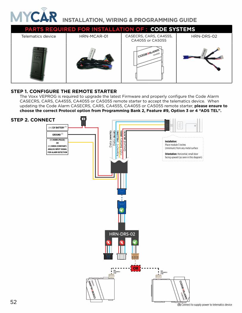
52
PARTS REQUIRED FOR INSTALLATION OF : CODE SYSTEMSTelematics device HRN-MCAR-01 CASECRS, CARS, CA4555,
CA4055 or CA5055HRN-DRS-02
STEP 1. CONFIGURE THE REMOTE STARTERThe Voxx VEPROG is required to upgrade the latest Firmware and properly configure the Code Alarm CASECRS, CARS, CA4555, CA4055 or CA5055 remote starter to accept the telematics device. When updating the Code Alarm CASECRS, CARS, CA4555, CA4055 or CA5055 remote starter, please ensure to choose the correct Protocol option from Programming Bank 2, Feature #9, Option 3 or 4 “ADS TEL”.
STEP 2. CONNECT
(+) HORN (PULSE) OR
(+) SIREN (CONSTANT)ANALOG INPUT SIGNAL FOR ALARM DETECTION
(+) 12V BATTERY (1)
GROUND (1)
+12
V B
atte
ry (RED)
Gro
und
(BLA
CK)
Dat
a (W
HITE)
Dat
a (B
LUE)
Ala
rm(+
) (YELL
OW
)
Installation: Place module 3 inches (minimum) from any metal surface
Orientation: Horizontal; small door facing upward (as seen in this diagram)
OR
3
HRN-DRS-02
(1) Connect to supply power to telematics device
INSTALLATION, WIRING & PROGRAMMING GUIDE

STEP 3. NETWORK CONNECTIVITYOnce the telematics module is connected into the remote starter, two LED’s will display to which networks you are connected to. (See LED Status Reference Chart on last page for details). NOTE: The vehicle may need to be outside in an open area in order to connect to a cellular and/or GPS network.
STEP 4. ADD A DEVICE/VEHICLE TO AN ACCOUNTa. Click the “+” sign at the bottom right of the Application screen. This will allow you to temporarily add
your customers device/vehicle to your personal account.b. Enter the 16 digit “Serial Number” found at the back of the telematic device
(SN: XXXXXX-XXXXXXXXXX) and Click “Submit the code”.c. You are now in “Test Mode”. Test Mode will allow you up to 4 hours for you to test the newly
installed device. At any time during this 4 hour period, you can exit testing mode and make unit “Ready for Customer Delivery” by “Releasing the vehicle” or by “Transfering the vehicle” from your account. NOTE: If you do NOT remove the vehicle from your account, it will automatically be removed from your account and make the unit “Ready for Customer Delivery”.
STEP 5. PRE-CONFIGURE MYCAR APPLICATION EXPERIENCE FOR YOUR CUSTOMERa. Click on the newly added vehicle from the vehicle list to enter the control screen (the screen that will al-
low you to control the vehicle’s remote start functions). This will automatically take you to the “Vehicle Configuration” page for this vehicle. You will be prompt to “Set a Bypass Protocol” to use this device. Click “Ok”.
b. Now you must set the protocol for the telematic device. When combined with the Code Alarm remote starter previously installed, you must set the protocol to “ADS” and click “ACCEPT” then click “Done” at the top right corner.
c. Now please allow a moment (About 5 minutes) for the telematic device to update your protocol selec-tion and reboot. After this wait period it will be available to accept commands from the App. In the vehicle control screen, the Device Signal icon located above the Stop button will display the connectiv-ity status of your telematic device. If the icon is Grayed out, Please wait, Device is still Offline. If icon is Green, Device is Online and Ready to go.
d. Then from the top right click on of the Settings section edit the Vehicle name, configure the Auxiliaries that might have been added if applicable and click ACCEPT when done. Then choose the vehicle to display inside the control panel in the VEHICLE IMAGE section and click ACCEPT once done.
e. When your configurations are all completed, click “Done” at the top right corner. All Configurations will take effect.
STEP 6. TEST YOUR DEVICEWhen the system is Online you start testing the unit from the vehicle control panel. Test all the application functions (Start, Stop, Lock, Unlock, Auxiliaries, ETC.) When done with the testing, from the vehicle list you can “Release” the vehicle. There are 2x different method to release it to the new owner. Choosing “release” will simply remove it from your account and make it “Ready for Customer Delivery”. Choosing “transfer” will transfer the device to the new owner’s account.
Also make sure that the Owners Card is handed to the New Owner of the vehicle. Doing this will ensure that the instructions on how to setup their App, Account and Vehicle is done correctly by using the device serial number located on the sticker affixed by the installer at the time of installation.
INSTALLATION, WIRING & PROGRAMMING GUIDE

54
PARTS REQUIRED FOR INSTALLATION OF : OLDER CODE SYSTEMSTelematics device HRN-MCAR-01 OLDER CODE SYSTEMS HRN-DRS-02
IMPORTANT NOTE: THESE OLDER MODELS ARE NOT SUPPORTED BY THIS PRODUCT.
INSTALLATION, WIRING & PROGRAMMING GUIDE

INSTALLATION, WIRING & PROGRAMMING GUIDE

56
PARTS REQUIRED FOR INSTALLATION OF : OMEGA RS-X70Telematics device HRN-MCAR-01 RS-X70 OL-ADAPTER-B2G
OL-ADAPTER-B2G
STEP 1. CONFIGURE THE REMOTE STARTERThe ADS Weblink (ADS-USB) is required to properly configure the Omega RS-X70 remote starter to accept the telematics device. When flashing the Omega RS-X70 remote starter, please ensure the remote starter firmware is updated to the latest firmware available. Also ensure to set the “Data Port Protocol” to : “Green = iData”.
STEP 2. CONNECT
(1) Connect only when remote starter is not supplying power to telematics device
HRN-DRS-02 & HRN-LLRS-01
3
(+) HORN (PULSE) OR
(+) SIREN (CONSTANT)ANALOG INPUT SIGNAL FOR ALARM DETECTION
(+) 12V BATTERY (1)
GROUND (1)
+12
V B
atte
ry (RED)
Gro
und
(BLA
CK)
Dat
a (W
HITE)
Dat
a (B
LUE)
Ala
rm(+
) (YELL
OW
)
Installation: Place module 3 inches (minimum) from any metal surface
Orientation: Horizontal; small door facing upward (as seen in this diagram)
HRN-DRS-01HRN-LLRS-01
OR
OL-A
DAPT
ER-B
2G
GREE
NDA
TA P
ORT
METHOD #1
METHOD #2
METHOD #3
INSTALLATION, WIRING & PROGRAMMING GUIDE

STEP 3. NETWORK CONNECTIVITYOnce the telematics module is connected into the remote starter, two LED’s will display to which networks you are connected to. (See LED Status Reference Chart on last page for details). NOTE: The vehicle may need to be outside in an open area in order to connect to a cellular and/or GPS network.
STEP 4. ADD A DEVICE/VEHICLE TO AN ACCOUNTa. Click the “+” sign at the bottom right of the Application screen. This will allow you to temporarily add
your customers device/vehicle to your personal account.b. Enter the 16 digit “Serial Number” found at the back of the telematic device
(SN: XXXXXX-XXXXXXXXXX) and Click “Submit the code”.c. You are now in “Test Mode”. Test Mode will allow you up to 4 hours for you to test the newly
installed device. At any time during this 4 hour period, you can exit testing mode and make unit “Ready for Customer Delivery” by “Releasing the vehicle” or by “Transfering the vehicle” from your account. NOTE: If you do NOT remove the vehicle from your account, it will automatically be removed from your account and make the unit “Ready for Customer Delivery”.
STEP 5. PRE-CONFIGURE MYCAR APPLICATION EXPERIENCE FOR YOUR CUSTOMERa. Click on the newly added vehicle from the vehicle list to enter the control screen (the screen that will al-
low you to control the vehicle’s remote start functions). This will automatically take you to the “Vehicle Configuration” page for this vehicle. You will be prompt to “Set a Bypass Protocol” to use this device. Click “Ok”.
b. Now you must set the protocol for the telematic device. When combined with the Omega RS-X70 remote starter previously installed, you must set the protocol to “ADS” and click “ACCEPT” then click “Done” at the top right corner.
c. Now please allow a moment (About 5 minutes) for the telematic device to update your protocol selec-tion and reboot. After this wait period it will be available to accept commands from the App. In the vehicle control screen, the Device Signal icon located above the Stop button will display the connectiv-ity status of your telematic device. If the icon is Grayed out, Please wait, Device is still Offline. If icon is Green, Device is Online and Ready to go.
d. Then from the top right click on of the Settings section edit the Vehicle name, configure the Auxiliaries that might have been added if applicable and click ACCEPT when done. Then choose the vehicle to display inside the control panel in the VEHICLE IMAGE section and click ACCEPT once done.
e. When your configurations are all completed, click “Done” at the top right corner. All Configurations will take effect.
STEP 6. TEST YOUR DEVICEWhen the system is Online you start testing the unit from the vehicle control panel. Test all the application functions (Start, Stop, Lock, Unlock, Auxiliaries, ETC.) When done with the testing, from the vehicle list you can “Release” the vehicle. There are 2x different method to release it to the new owner. Choosing “release” will simply remove it from your account and make it “Ready for Customer Delivery”. Choosing “transfer” will transfer the device to the new owner’s account.
Also make sure that the Owners Card is handed to the New Owner of the vehicle. Doing this will ensure that the instructions on how to setup their App, Account and Vehicle is done correctly by using the device serial number located on the sticker affixed by the installer at the time of installation.
INSTALLATION, WIRING & PROGRAMMING GUIDE

58
PARTS REQUIRED FOR INSTALLATION OF : OMEGA AL-XX70-BTelematics device HRN-MCAR-01 AL-XX70-B OL-
ADAPTER-B2G
OL-BLADE-AL (64)
OL-ADAPTER-B2G
STEP 1. CONFIGURE THE REMOTE STARTERThe ADS Weblink (ADS-USB) is required to properly configure the Omega AL-XX70-B remote starter to accept the telematics device. When flashing the Omega AL-XX70-B remote starter, please ensure the remote starter firmware and BLADE-AL (64) firmwares are updated to the latest firmware available. Also ensure to set the “Data Port Protocol” to : “Green = iData”.
STEP 2. CONNECT
(1) Connect only when remote starter is not supplying power to telematics device
HRN-DRS-02 &
HRN-LLRS-01
3
(+) HORN (PULSE) OR
(+) SIREN (CONSTANT)ANALOG INPUT SIGNAL FOR ALARM DETECTION
(+) 12V BATTERY (1)
GROUND (1)
+12
V B
atte
ry (RED)
Gro
und
(BLA
CK)
Dat
a (W
HITE)
Dat
a (B
LUE)
Ala
rm(+
) (YELL
OW
)
Installation: Place module 3 inches (minimum) from any metal surface
Orientation: Horizontal; small door facing upward (as seen in this diagram)
HRN-DRS-01HRN-LLRS-01
OR
OL-A
DAPT
ER-B
2G
GREE
NDA
TA P
ORT
METHOD #1
METHOD #2
METHOD #3
INSTALLATION, WIRING & PROGRAMMING GUIDE

STEP 3. NETWORK CONNECTIVITYOnce the telematics module is connected into the remote starter, two LED’s will display to which networks you are connected to. (See LED Status Reference Chart on last page for details). NOTE: The vehicle may need to be outside in an open area in order to connect to a cellular and/or GPS network.
STEP 4. ADD A DEVICE/VEHICLE TO AN ACCOUNTa. Click the “+” sign at the bottom right of the Application screen. This will allow you to temporarily add
your customers device/vehicle to your personal account.b. Enter the 16 digit “Serial Number” found at the back of the telematic device
(SN: XXXXXX-XXXXXXXXXX) and Click “Submit the code”.c. You are now in “Test Mode”. Test Mode will allow you up to 4 hours for you to test the newly
installed device. At any time during this 4 hour period, you can exit testing mode and make unit “Ready for Customer Delivery” by “Releasing the vehicle” or by “Transfering the vehicle” from your account. NOTE: If you do NOT remove the vehicle from your account, it will automatically be removed from your account and make the unit “Ready for Customer Delivery”.
STEP 5. PRE-CONFIGURE MYCAR APPLICATION EXPERIENCE FOR YOUR CUSTOMERa. Click on the newly added vehicle from the vehicle list to enter the control screen (the screen that will al-
low you to control the vehicle’s remote start functions). This will automatically take you to the “Vehicle Configuration” page for this vehicle. You will be prompt to “Set a Bypass Protocol” to use this device. Click “Ok”.
b. Now you must set the protocol for the telematic device. When combined with the Omega AL-XX70-B remote starter previously installed, you must set the protocol to “ADS” and click “ACCEPT” then click “Done” at the top right corner.
c. Now please allow a moment (About 5 minutes) for the telematic device to update your protocol selec-tion and reboot. After this wait period it will be available to accept commands from the App. In the vehicle control screen, the Device Signal icon located above the Stop button will display the connectiv-ity status of your telematic device. If the icon is Grayed out, Please wait, Device is still Offline. If icon is Green, Device is Online and Ready to go.
d. Then from the top right click on of the Settings section edit the Vehicle name, configure the Auxiliaries that might have been added if applicable and click ACCEPT when done. Then choose the vehicle to display inside the control panel in the VEHICLE IMAGE section and click ACCEPT once done.
e. When your configurations are all completed, click “Done” at the top right corner. All Configurations will take effect.
STEP 6. TEST YOUR DEVICEWhen the system is Online you start testing the unit from the vehicle control panel. Test all the application functions (Start, Stop, Lock, Unlock, Auxiliaries, ETC.) When done with the testing, from the vehicle list you can “Release” the vehicle. There are 2x different method to release it to the new owner. Choosing “release” will simply remove it from your account and make it “Ready for Customer Delivery”. Choosing “transfer” will transfer the device to the new owner’s account.
Also make sure that the Owners Card is handed to the New Owner of the vehicle. Doing this will ensure that the instructions on how to setup their App, Account and Vehicle is done correctly by using the device serial number located on the sticker affixed by the installer at the time of installation.
INSTALLATION, WIRING & PROGRAMMING GUIDE

60
PARTS REQUIRED FOR INSTALLATION OF : OMEGA OLRSTelematics device HRN-MCAR-01 Omega OLRS
STEP 1. CONFIGURE THE REMOTE STARTERThe ADS Weblink (ADS-USB) is required to properly configure the Omega OLRS remote starter to accept the telematic device. When flashing the Omega OLRS remote starter, please ensure to choose the “Linkr” telematics protocol.
STEP 2. CONNECT
(1) Connect only when remote starter is not supplying power to telematics device
3
(+) HORN (PULSE) OR
(+) SIREN (CONSTANT)ANALOG INPUT SIGNAL FOR ALARM DETECTION
(+) 12V BATTERY (1)
GROUND (1)
+12
V B
atte
ry (RED)
Gro
und
(BLA
CK)
Dat
a (W
HITE)
Dat
a (B
LUE)
Ala
rm(+
) (YELL
OW
)
Installation: Place module 3 inches (minimum) from any metal surface
Orientation: Horizontal; small door facing upward (as seen in this diagram)
INSTALLATION, WIRING & PROGRAMMING GUIDE

STEP 3. NETWORK CONNECTIVITYOnce the telematics module is connected into the remote starter, two LED’s will display to which networks you are connected to. (See LED Status Reference Chart on last page for details). NOTE: The vehicle may need to be outside in an open area in order to connect to a cellular and/or GPS network.
STEP 4. ADD A DEVICE/VEHICLE TO AN ACCOUNTa. Click the “+” sign at the bottom right of the Application screen. This will allow you to temporarily add your
customers device/vehicle to your personal account.b. Enter the 16 digit “Serial Number” found at the back of the telematic device
(SN: XXXXXX-XXXXXXXXXX) and Click “Submit the code”.c. You are now in “Test Mode”. Test Mode will allow you up to 4 hours for you to test the newly
installed device. At any time during this 4 hour period, you can exit testing mode and make unit “Ready for Customer Delivery” by “Releasing the vehicle” or by “Transfering the vehicle” from your account. NOTE: If you do NOT remove the vehicle from your account, it will automatically be removed from your account and make the unit “Ready for Customer Delivery”.
STEP 5. PRE-CONFIGURE MYCAR APPLICATION EXPERIENCE FOR YOUR CUSTOMERa. Click on the newly added vehicle from the vehicle list to enter the control screen (the screen that will allow
you to control the vehicle’s remote start functions). This will automatically take you to the “Vehicle Con-figuration” page for this vehicle. You will be prompt to “Set a Bypass Protocol” to use this device. Click “Ok”.
b. Now you must set the protocol for the telematic device. When combined with the Flashlogic FLRS remote starter previously installed, you must set the protocol to “ADS” and click “ACCEPT” then click “Done” at the top right corner.
c. Now please allow a moment (About 5 minutes) for the telematic device to update your protocol selection and reboot. After this wait period it will be available to accept commands from the App. In the vehicle control screen, the Device Signal icon located above the Stop button will display the connectivity status of your telematic device. If the icon is Grayed out, Please wait, Device is still Offline. If icon is Green, De-vice is Online and Ready to go.
d. Then from the top right click on of the Settings section edit the Vehicle name, configure the Auxiliaries that might have been added if applicable and click ACCEPT when done. Then choose the vehicle to display inside the control panel in the VEHICLE IMAGE section and click ACCEPT once done.
e. When your configurations are all completed, click “Done” at the top right corner. All Configurations will take effect.
STEP 6. TEST YOUR DEVICEWhen the system is Online you start testing the unit from the vehicle control panel. Test all the application functions (Start, Stop, Lock, Unlock, Auxiliaries, ETC.) When done with the testing, from the vehicle list you can “Release” the vehicle. There are 2x different method to release it to the new owner. Choosing “release” will simply remove it from your account and make it “Ready for Customer Delivery”. Choosing “transfer” will transfer the device to the new owner’s account.
Also make sure that the Owners Card is handed to the New Owner of the vehicle. Doing this will ensure that the instructions on how to setup their App, Account and Vehicle is done correctly by using the device serial number located on the sticker affixed by the installer at the time of installation.
INSTALLATION, WIRING & PROGRAMMING GUIDE

62
PARTS REQUIRED FOR INSTALLATION OF : MIDCITY SMARTKEY STARTERTelematics device HRN-MCAR-01 NG Remote Starter
STEP 1. CONFIGURE THE REMOTE STARTERThe Smartkey Starter NG series is already pre-configured to accept the telematics device. No extra programming required.
STEP 2. CONNECT3
(+) HORN (PULSE) OR
(+) SIREN (CONSTANT)ANALOG INPUT SIGNAL FOR ALARM DETECTION
(+) 12V BATTERY (1)
GROUND (1)
+12
V B
atte
ry (RED)
Gro
und
(BLA
CK)
Dat
a (W
HITE)
Dat
a (B
LUE)
Ala
rm(+
) (YELL
OW
)
Installation: Place module 3 inches (minimum) from any metal surface
Orientation: Horizontal; small door facing upward (as seen in this diagram)
(1) Connect only when remote starter is not supplying power to telematics device
INSTALLATION, WIRING & PROGRAMMING GUIDE

STEP 3. NETWORK CONNECTIVITYOnce the telematics module is connected into the remote starter, two LED’s will display to which networks you are connected to. (See LED Status Reference Chart on last page for details). NOTE: The vehicle may need to be outside in an open area in order to connect to a cellular and/or GPS network.
STEP 4. ADD A DEVICE/VEHICLE TO AN ACCOUNTa. Click the “+” sign at the bottom right of the Application screen. This will allow you to temporarily add
your customers device/vehicle to your personal account.b. Enter the 16 digit “Serial Number” found at the back of the telematic device
(SN: XXXXXX-XXXXXXXXXX) and Click “Submit the code”.c. You are now in “Test Mode”. Test Mode will allow you up to 4 hours for you to test the newly
installed device. At any time during this 4 hour period, you can exit testing mode and make unit “Ready for Customer Delivery” by “Releasing the vehicle” or by “Transfering the vehicle” from your account. NOTE: If you do NOT remove the vehicle from your account, it will automatically be removed from your account and make the unit “Ready for Customer Delivery”.
STEP 5. PRE-CONFIGURE MYCAR APPLICATION EXPERIENCE FOR YOUR CUSTOMERa. Click on the newly added vehicle from the vehicle list to enter the control screen (the screen that will al-
low you to control the vehicle’s remote start functions). This will automatically take you to the “Vehicle Configuration” page for this vehicle. You will be prompt to “Set a Bypass Protocol” to use this device. Click “Ok”.
b. Now you must set the protocol for the telematic device. When combined with the Smartkey Starter NG series remote starter previously installed, you must set the protocol to “ADS” and click “ACCEPT” then click “Done” at the top right corner.
c. Now please allow a moment (About 5 minutes) for the telematic device to update your protocol selec-tion and reboot. After this wait period it will be available to accept commands from the App. In the vehicle control screen, the Device Signal icon located above the Stop button will display the connectiv-ity status of your telematic device. If the icon is Grayed out, Please wait, Device is still Offline. If icon is Green, Device is Online and Ready to go.
d. Then from the top right click on of the Settings section edit the Vehicle name, configure the Auxiliaries that might have been added if applicable and click ACCEPT when done. Then choose the vehicle to display inside the control panel in the VEHICLE IMAGE section and click ACCEPT once done.
e. When your configurations are all completed, click “Done” at the top right corner. All Configurations will take effect.
STEP 6. TEST YOUR DEVICEWhen the system is Online you start testing the unit from the vehicle control panel. Test all the application functions (Start, Stop, Lock, Unlock, Auxiliaries, ETC.) When done with the testing, from the vehicle list you can “Release” the vehicle. There are 2x different method to release it to the new owner. Choosing “release” will simply remove it from your account and make it “Ready for Customer Delivery”. Choosing “transfer” will transfer the device to the new owner’s account.
Also make sure that the Owners Card is handed to the New Owner of the vehicle. Doing this will ensure that the instructions on how to setup their App, Account and Vehicle is done correctly by using the device serial number located on the sticker affixed by the installer at the time of installation.
INSTALLATION, WIRING & PROGRAMMING GUIDE

64
PARTS REQUIRED FOR INSTALLATION OF : DSE 503AIR 5R-85Telematics device HRN-MCAR-01 DSE 503AIR 5R85
STEP 1. CONFIGURE THE REMOTE STARTERThe 503Air is already pre-configured to accept the telematics device. No extra programming required.
STEP 2. CONNECT
3
(+) HORN (PULSE) OR
(+) SIREN (CONSTANT)ANALOG INPUT SIGNAL FOR ALARM DETECTION
(+) 12V BATTERY (1)
GROUND (1)
+12
V B
atte
ry (RED)
Gro
und
(BLA
CK)
Dat
a (W
HITE)
Dat
a (B
LUE)
Ala
rm(+
) (YELL
OW
)
Installation: Place module 3 inches (minimum) from any metal surface
Orientation: Horizontal; small door facing upward (as seen in this diagram)
(1) Connect only when remote starter is not supplying power to telematics device
INSTALLATION, WIRING & PROGRAMMING GUIDE

STEP 3. NETWORK CONNECTIVITYOnce the telematics module is connected into the remote starter, two LED’s will display to which networks you are connected to. (See LED Status Reference Chart on last page for details). NOTE: The vehicle may need to be outside in an open area in order to connect to a cellular and/or GPS network.
STEP 4. ADD A DEVICE/VEHICLE TO AN ACCOUNTa. Click the “+” sign at the bottom right of the Application screen. This will allow you to temporarily add
your customers device/vehicle to your personal account.b. Enter the 16 digit “Serial Number” found at the back of the telematic device
(SN: XXXXXX-XXXXXXXXXX) and Click “Submit the code”.c. You are now in “Test Mode”. Test Mode will allow you up to 4 hours for you to test the newly
installed device. At any time during this 4 hour period, you can exit testing mode and make unit “Ready for Customer Delivery” by “Releasing the vehicle” or by “Transfering the vehicle” from your account. NOTE: If you do NOT remove the vehicle from your account, it will automatically be removed from your account and make the unit “Ready for Customer Delivery”.
STEP 5. PRE-CONFIGURE MYCAR APPLICATION EXPERIENCE FOR YOUR CUSTOMERa. Click on the newly added vehicle from the vehicle list to enter the control screen (the screen that will al-
low you to control the vehicle’s remote start functions). This will automatically take you to the “Vehicle Configuration” page for this vehicle. You will be prompt to “Set a Bypass Protocol” to use this device. Click “Ok”.
b. Now you must set the protocol for the telematic device. When combined with the DSE 503AIR remote starter previously installed, you must set the protocol to “ADS” and click “ACCEPT” then click “Done” at the top right corner.
c. Now please allow a moment (About 5 minutes) for the telematic device to update your protocol selec-tion and reboot. After this wait period it will be available to accept commands from the App. In the vehicle control screen, the Device Signal icon located above the Stop button will display the connectiv-ity status of your telematic device. If the icon is Grayed out, Please wait, Device is still Offline. If icon is Green, Device is Online and Ready to go.
d. Then from the top right click on of the Settings section edit the Vehicle name, configure the Auxiliaries that might have been added if applicable and click ACCEPT when done. Then choose the vehicle to display inside the control panel in the VEHICLE IMAGE section and click ACCEPT once done.
e. When your configurations are all completed, click “Done” at the top right corner. All Configurations will take effect.
STEP 6. TEST YOUR DEVICEWhen the system is Online you start testing the unit from the vehicle control panel. Test all the application functions (Start, Stop, Lock, Unlock, Auxiliaries, ETC.) When done with the testing, from the vehicle list you can “Release” the vehicle. There are 2x different method to release it to the new owner. Choosing “release” will simply remove it from your account and make it “Ready for Customer Delivery”. Choosing “transfer” will transfer the device to the new owner’s account.
Also make sure that the Owners Card is handed to the New Owner of the vehicle. Doing this will ensure that the instructions on how to setup their App, Account and Vehicle is done correctly by using the device serial number located on the sticker affixed by the installer at the time of installation.
INSTALLATION, WIRING & PROGRAMMING GUIDE

66
PARTS REQUIRED FOR INSTALLATION OF : DSE iSTART2 - 3Telematics device HRN-MCAR-01 DSE iStart2 - 3 CI3R-86 BLADE-AL (64)
STEP 1. CONFIGURE THE REMOTE STARTERThe ADS Weblink (ADS-USB) is required to properly configure the DSE iStart2 - iStart3 remote starter to ac-cept the telematics device. When flashing the DSE iStart2 - iStart3 remote starter, please ensure the remote starter firmware and BLADE-AL (64) firmwares are updated to the latest firmware available.
STEP 2. CONNECT
3
(+) HORN (PULSE) OR
(+) SIREN (CONSTANT)ANALOG INPUT SIGNAL FOR ALARM DETECTION
(+) 12V BATTERY (1)
GROUND (1)
+12
V B
atte
ry (RED)
Gro
und
(BLA
CK)
Dat
a (W
HITE)
Dat
a (B
LUE)
Ala
rm(+
) (YELL
OW
)
Installation: Place module 3 inches (minimum) from any metal surface
Orientation: Horizontal; small door facing upward (as seen in this diagram)
(1) Connect only when remote starter is not supplying power to telematics device
INSTALLATION, WIRING & PROGRAMMING GUIDE

STEP 3. NETWORK CONNECTIVITYOnce the telematics module is connected into the remote starter, two LED’s will display to which networks you are connected to. (See LED Status Reference Chart on last page for details). NOTE: The vehicle may need to be outside in an open area in order to connect to a cellular and/or GPS network.
STEP 4. ADD A DEVICE/VEHICLE TO AN ACCOUNTa. Click the “+” sign at the bottom right of the Application screen. This will allow you to temporarily add
your customers device/vehicle to your personal account.b. Enter the 16 digit “Serial Number” found at the back of the telematic device
(SN: XXXXXX-XXXXXXXXXX) and Click “Submit the code”.c. You are now in “Test Mode”. Test Mode will allow you up to 4 hours for you to test the newly
installed device. At any time during this 4 hour period, you can exit testing mode and make unit “Ready for Customer Delivery” by “Releasing the vehicle” or by “Transfering the vehicle” from your account. NOTE: If you do NOT remove the vehicle from your account, it will automatically be removed from your account and make the unit “Ready for Customer Delivery”.
STEP 5. PRE-CONFIGURE MYCAR APPLICATION EXPERIENCE FOR YOUR CUSTOMERa. Click on the newly added vehicle from the vehicle list to enter the control screen (the screen that will al-
low you to control the vehicle’s remote start functions). This will automatically take you to the “Vehicle Configuration” page for this vehicle. You will be prompt to “Set a Bypass Protocol” to use this device. Click “Ok”.
b. Now you must set the protocol for the telematic device. When combined with the DSE iStart2 - iStart3 remote starter previously installed, you must set the protocol to “ADS” and click “ACCEPT” then click “Done” at the top right corner.
c. Now please allow a moment (About 5 minutes) for the telematic device to update your protocol selec-tion and reboot. After this wait period it will be available to accept commands from the App. In the vehicle control screen, the Device Signal icon located above the Stop button will display the connectiv-ity status of your telematic device. If the icon is Grayed out, Please wait, Device is still Offline. If icon is Green, Device is Online and Ready to go.
d. Then from the top right click on of the Settings section edit the Vehicle name, configure the Auxiliaries that might have been added if applicable and click ACCEPT when done. Then choose the vehicle to display inside the control panel in the VEHICLE IMAGE section and click ACCEPT once done.
e. When your configurations are all completed, click “Done” at the top right corner. All Configurations will take effect.
STEP 6. TEST YOUR DEVICEWhen the system is Online you start testing the unit from the vehicle control panel. Test all the application functions (Start, Stop, Lock, Unlock, Auxiliaries, ETC.) When done with the testing, from the vehicle list you can “Release” the vehicle. There are 2x different method to release it to the new owner. Choosing “release” will simply remove it from your account and make it “Ready for Customer Delivery”. Choosing “transfer” will transfer the device to the new owner’s account.
Also make sure that the Owners Card is handed to the New Owner of the vehicle. Doing this will ensure that the instructions on how to setup their App, Account and Vehicle is done correctly by using the device serial number located on the sticker affixed by the installer at the time of installation.
INSTALLATION, WIRING & PROGRAMMING GUIDE

68
LED Status Reference ChartLED Status GREEN LED : Cellular Network RED LED : GPS Network
OFF No Cellular Network. No power to device. No GPS Network. No power to device.
Flashing Searching/Connecting Searching/Connecting
ON Solid Connection is established Connection is established
RESET PROCEDURE 1 - Disconnect the main harness from the MyCar device. 2 - Wait approximately 10 seconds and reconnect the main harness to the MyCar device. 3 - Reset procedure Completed.
INSTALLATION, WIRING & PROGRAMMING GUIDE

INSTALLATION, WIRING & PROGRAMMING GUIDE

©2019 Automobility Distribution Inc. All rights reserved. © 2018 Automobility Distribution Inc. All rights reserved.
400 Wright st. St-Laurent, Quebec, Canada, H4N1M6
400 Wright st.Ville St-Laurent, Quebec
H4N1M6 - CANADA