completely redesigned - wireless broadband, … · self-supporting towers rsl completely redesigned...
TRANSCRIPT
SE
LF
-SU
PP
OR
TIN
G T
OW
ER
SRS
LCOMPLETELY REDESIGNEDThe all new
GENERAL USE
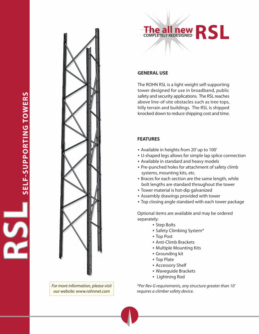
The ROHN RSL is a light weight self-supportingtower designed for use in broadband, publicsafety and security applications. The RSL reachesabove line-of-site obstacles such as tree tops, hilly terrain and buildings. The RSL is shippedknocked down to reduce shipping cost and time.
FEATURES
• Available in heights from 20’ up to 100’• U-shaped legs allows for simple lap splice connection• Available in standard and heavy models• Pre-punched holes for attachment of safety climb systems, mounting kits, etc.• Braces for each section are the same length, while bolt lengths are standard throughout the tower• Tower material is hot-dip galvanized• Assembly drawings provided with tower• Top closing angle standard with each tower package
Optional items are available and may be orderedseparately: • Step Bolts • Safety Climbing System* • Top Post • Anti-Climb Brackets • Multiple Mounting Kits • Grounding kit • Top Plate • Accessory Shelf • Waveguide Brackets • Lightning Rod
*Per Rev G requirements, any structure greater than 10’ requires a climber safety device.
RSL
For more information, please visitour website: www.rohnnet.com
ORDERING INFO
1
1. The suitability of a ROHN standard RSL tower kit and standard foundation for a speci�c application must be veri�ed by the purchaser based on site-speci�c data in accordance with the ANSI/TIA-222-G Standard. All users are solely responsible for the installation, use, maintenance, inspection and other work and the compliance with all local, state and federal requirements.2. The allowable E�ective Projected Areas (EPA) tabulated for the standard RSL tower kits represent the summation of the projected areas of all antennas, mounts and accessories multiplied by appropriate dragfactors. The tabulated EPA values are in addition to the loading from a 3/8 inch diameter safety cable assumed to be mounted to each standard tower. The tabulated EPA values are for a no-ice condition. For design purposes, the tabulated EPA values have been increased 75% when investigating extreme ice loading conditions. 3. The tabulated EPA values apply to towers located on sites with level grade (ANSI/TIA-222-G TopographicCategory 1). Lower EPA values than tabulated would apply for roof mounted towers or for towers located on sites with unusual terrain. Contact ROHN for site-speci�c design limitations.4. The RSL standard designs are based on one 1/2 inch transmission line for each 10 square feet of EPA up to a maximum of 6 lines unless otherwise noted. All lines are assumed to be symmetrically mounted on thetower faces adjacent to a leg.5. The total weight of all antennas and mounts associated with the tabulated EPA values is assumed toequal 500 pounds for the no-ice condition and 1000 pounds for the extreme ice condition.6. The tabulated EPA values assume the associated antennas and appurtenances are symmetrically mounted unless otherwise noted. Eccentric loading may increase member forces and may require areduction of the tabulated EPA values. Mounting arrangements are assumed to be appropriate for the supporting members utilized. Contact ROHN if assistance is needed in determining the adequacy of a speci�c RSL tower kit for site-speci�c loading conditions. 7. The RSL standard top mast is designed to support a maximum EPA of 5 square feet with 100 pounds vertical load. Other optional top mounts are available upon request. All other loading is assumed to be mounted to the tower below the top mast. 8. The standard RSL tower kits that include dish loading criteria meet ANSI/TIA-222-G twist and sway requirements for a 6 GHz dish frequency. All dishes are assumed to be face mounted. Contact ROHN for assistance with higher frequency or other mounting arrangement applications.
SE
LF
-SU
PP
OR
TIN
G T
OW
ER
SRSL1. Foundation bases must be ordered separately.
2. All accessories must be ordered separately including step bolt kits, safety climb systems, climbing harness with slider, grounding kits, lightning rods, top plate, top mast, mounting kits, W/G brackets, anti-climb assemblies, etc. 3. ROHN standard RSL tower kits are supplied with lock washers as nut locking devices. Pal nuts (P), anco nuts (A) and tri-loc nuts (T) are alternative nut locking devices that may be obtained by adding theindicated su�x to the standard RSL tower kit Part Number. (Note: nut locking devices are required inaccordance with ANSI/TIA-222-G.) Example: RSL100L10A for Anco Nuts.4. All three tower legs in each section have provision to install step bolts and a safety climb system. When step bolts are desired, one step bolt kit must be ordered for each section of the tower. Increase the number of step bolt kits accordingly when step bolts are desired on more than one tower leg of a section.
DESIGN NOTES
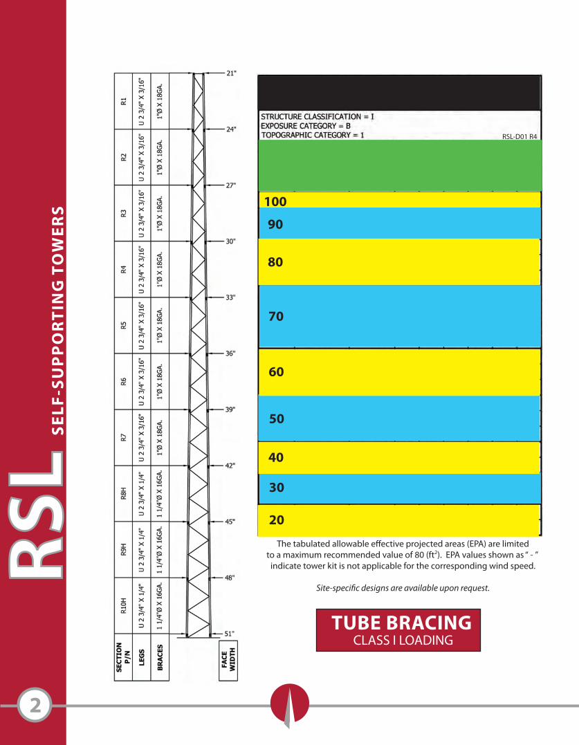
RSL-D01 R4
2
SE
LF
-SU
PP
OR
TIN
G T
OW
ER
SRS
L
The tabulated allowable e�ective projected areas (EPA) are limitedto a maximum recommended value of 80 (ft2). EPA values shown as “ - ”
indicate tower kit is not applicable for the corresponding wind speed.
Site-speci�c designs are available upon request.
TUBE BRACINGCLASS I LOADING
90
80
70
60
50
40
30
20
100
The tabulated allowable e�ective projected areas (EPA) are limitedto a maximum recommended value of 80 (ft2). EPA values shown as “ - ”
indicate tower kit is not applicable for the corresponding wind speed.
Site-speci�c designs are available upon request.
3
SE
LF
-SU
PP
OR
TIN
G T
OW
ER
SRSL
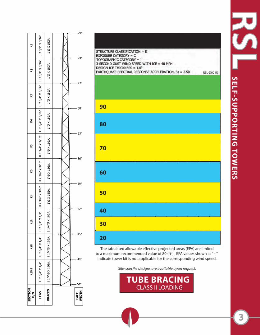
RSL-D02 R3
TUBE BRACINGCLASS II LOADING
90
50
20
30
40
60
70
80
The tabulated allowable e�ective projected areas (EPA) are limitedto a maximum recommended value of 80 (ft2). EPA values shown as “ - ”
indicate tower kit is not applicable for the corresponding wind speed.
Site-speci�c designs are available upon request.
4
SE
LF
-SU
PP
OR
TIN
G T
OW
ER
SRS
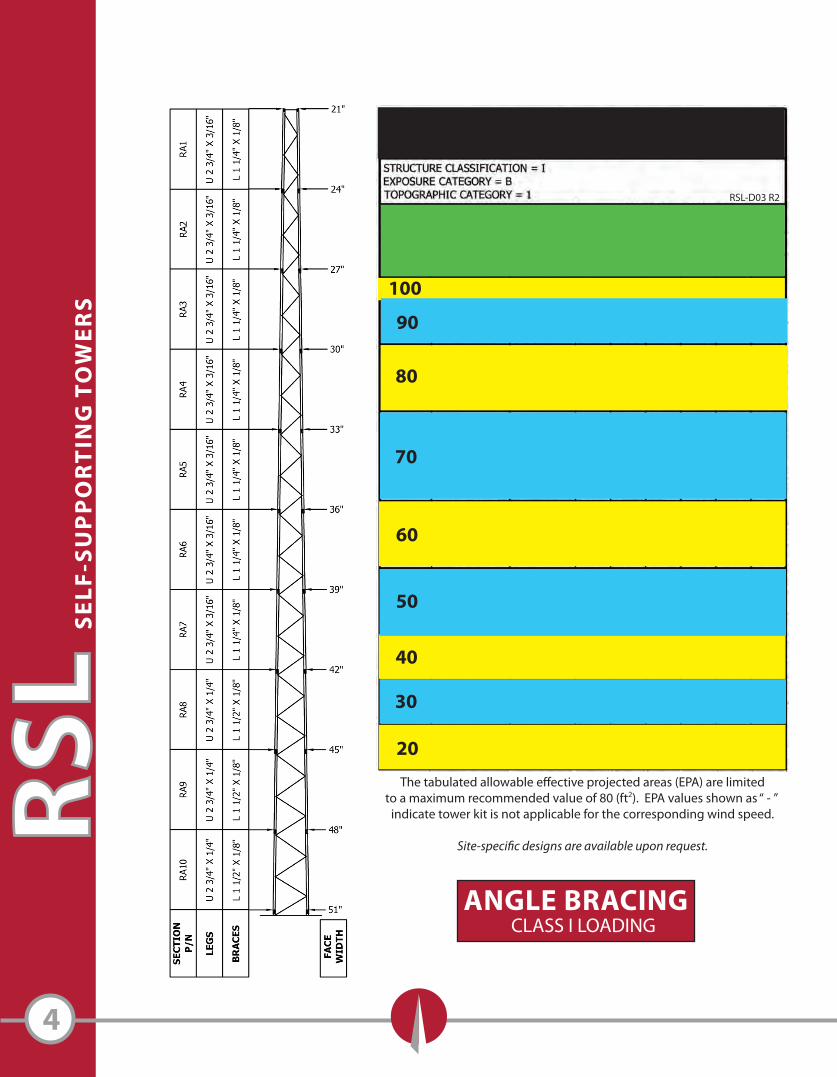
LRSL-D03 R2
ANGLE BRACINGCLASS I LOADING
80
70
60
50
40
30
20
100
90
90
80
70
60
50
40
30
20The tabulated allowable e�ective projected areas (EPA) are limited
to a maximum recommended value of 80 (ft2). EPA values shown as “ - ” indicate tower kit is not applicable for the corresponding wind speed.
Site-speci�c designs are available upon request.
5
SE
LF
-SU
PP
OR
TIN
G T
OW
ER
SRSL
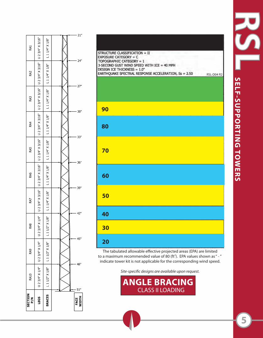
ANGLE BRACINGCLASS II LOADING
RSL-D04 R2
6
OPTIONAL ACCESSORIES
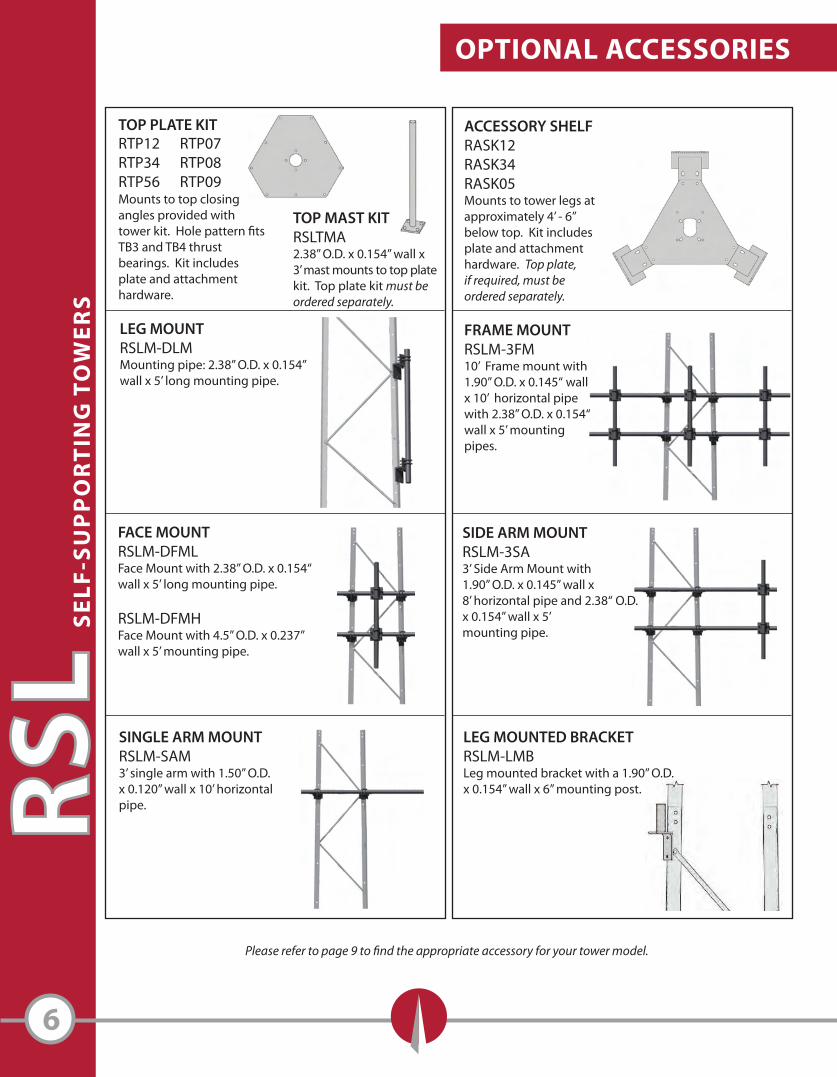
LEG MOUNTRSLM-DLMMounting pipe: 2.38” O.D. x 0.154” wall x 5’ long mounting pipe.
RTP12 RTP07RTP34 RTP08RTP56 RTP09
ACCESSORY SHELFRASK12 RASK34 RASK05 Mounts to tower legs at approximately 4’ - 6”below top. Kit includes plate and attachmenthardware. Top plate, if required, must beordered separately.
OPTIONAL ACCESSORIES
TOP MAST KITRSLTMA2.38” O.D. x 0.154” wall x3’ mast mounts to top platekit. Top plate kit must be ordered separately.
FRAME MOUNTRSLM-3FM10’ Frame mount with1.90” O.D. x 0.145“ wall x 10’ horizontal pipewith 2.38” O.D. x 0.154“ wall x 5’ mounting pipes.
SE
LF
-SU
PP
OR
TIN
G T
OW
ER
SRS
L
FACE MOUNTRSLM-DFMLFace Mount with 2.38” O.D. x 0.154“wall x 5’ long mounting pipe.
RSLM-DFMHFace Mount with 4.5” O.D. x 0.237” wall x 5’ mounting pipe.
TOP PLATE KIT
Mounts to top closingangles provided withtower kit. Hole pattern �tsTB3 and TB4 thrustbearings. Kit includesplate and attachmenthardware.
SINGLE ARM MOUNTRSLM-SAM3’ single arm with 1.50” O.D. x 0.120” wall x 10’ horizontal pipe.
Please refer to page 9 to �nd the appropriate accessory for your tower model.
LEG MOUNTED BRACKETRSLM-LMBLeg mounted bracket with a 1.90” O.D. x 0.154” wall x 6” mounting post.
SIDE ARM MOUNTRSLM-3SA3’ Side Arm Mount with1.90” O.D. x 0.145” wall x8’ horizontal pipe and 2.38“ O.D.x 0.154” wall x 5’mounting pipe.
7
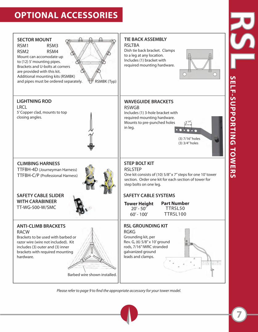
RSL GROUNDING KITRGKGGrounding kit, perRev. G, (6) 5/8” x 10’ groundrods, 7/16” IWRC stranded galvanized ground leads and clamps.
Tower Height20’ - 50‘
60’ - 100’
Part NumberTTRSL50
TTRSL100
SAFETY CABLE SLIDERWITH CARABINEERTT-WG-500-W/SMC
CLIMBING HARNESSTTFBH-4D (Journeyman Harness)TTFBH-C/P (Professional Harness)
SAFETY CABLE SYSTEMS
RSLSTEPOne kit consists of (10) 5/8” x 7” steps for one 10’ tower section. Order one kit for each section of tower forstep bolts on one leg.
STEP BOLT KIT
ANTI-CLIMB BRACKETSRACWBrackets to be used with barbed orrazor wire (wire not included). Kitincludes (3) outer and (3) inner brackets with required mountinghardware.
SE
LF
-SU
PP
OR
TIN
G T
OW
ER
SRSL
LIGHTNING RODLRCL5’ Copper clad, mounts to topclosing angles.
WAVEGUIDE BRACKETSRSWGBIncludes (1) 3-hole bracket with required mounting hardware. Mounts to pre-punched holesin leg.
SECTOR MOUNTRSM1 RSM3RSM2 RSM4Mount can accomodate upto (12) 5’ mounting pipes. Brackets and U-bolts at cornersare provided with this kit. Additional mounting kits (RSMBK)and pipes must be ordered separately.
TIE BACK ASSEMBLYRSLTBADish tie back bracket. Clamps to a leg at any location. Includes (1) bracket with required mounting hardware.
Please refer to page 9 to �nd the appropriate accessory for your tower model.
OPTIONAL ACCESSORIES
RSMBK (Typ)
Barbed wire shown installed.
2 1/4”
(3) 7/16” holes(3) 3/4” holes
ST
AN
DA
RD
RS
L S
EL
F-S
UP
PO
RT
ING
TO
WE
RS
(field
bo
lted
)
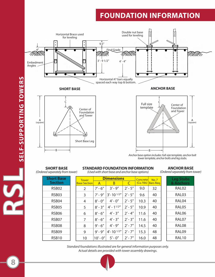
Final Grade4”
4’ - 4”
Horizontal Brace usedfor leveling
EmbedmentAngles
3’ - 9 1/2”
Horizontal #7 bars equallyspaced each way top & bottom.
A(square)
B
Center ofFoundationand Tower
9.5”
C
Standard foundations illustrated are for general information purposes only.Actual details are provided with tower assembly drawings.
SHORT BASE ANCHOR BASE
Short Base Leg
Anchor base option includes: full-size template, anchor boltlower template, anchor bolts and leg stubs.
FOUNDATION INFORMATION
8
Short Base Section
RSB02
RSB03
RSB04
RSB05
RSB06
RSB07
RSB08
RSB09
RSB10
Dimensions A
7’ - 6”
7’ - 9”
8’ - 0”
8’ - 3”
8’ - 6”
8’ - 6”
9’ - 6”
9’ - 9”
10’ - 0”
B3’ - 9”
3’ - 10 1/2”
4’ - 0”
4’ - 11/2”
4’ - 3”
4’ - 3”
4’ - 9”
4’ - 10 1/2”
5’ - 0”
C2’ - 5”
2’ - 5”
2’ - 5”
2’ - 5”
2’ - 4”
2’ - 3”
2’ - 7”
2’ - 7”
2’ - 7”
Concrete(Cu. Yds)
9.0
9.6
10.3
10.9
11.6
11.6
14.5
15.3
16.0
No. 7Bars Req.
32
40
40
40
40
40
40
48
48
Leg Stubs& Anchors
RAL02
RAL03
RAL04
RAL05
RAL06
RAL07
RAL08
RAL09
RAL10
STANDARD FOUNDATION INFORMATION(Used with short base and anchor base options)
SHORT BASE(Ordered separately from tower)
ANCHOR BASE(Ordered separately from tower)
Center ofFoundationand Tower
SE
LF
-SU
PP
OR
TIN
G T
OW
ER
SRS
LDouble nut baseused for leveling
TowerBase Section
2
3
4
5
6
7
8
9
10
Full sizetemplate
B
A(square)
C
9
SE
LF
-SU
PP
OR
TIN
G T
OW
ER
SRSL
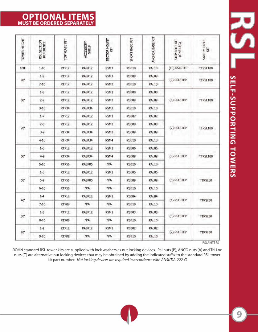
OPTIONAL ITEMSMUST BE ORDERED SEPARATELY
ROHN standard RSL tower kits are supplied with lock washers as nut locking devices. Pal nuts (P), ANCO nuts (A) and Tri-Loc nuts (T) are alternative nut locking devices that may be obtained by adding the indicated su�x to the standard RSL tower
kit part number. Nut locking devices are required in accordance with ANSI/TIA-222-G.
RSLAKITS R2