completion equipment
TRANSCRIPT

7242019 Completion Equipment
httpslidepdfcomreaderfullcompletion-equipment 184
Completion EquipmentTubulars
API Specifications for Oilfield Tubulars
The American Petroleum Institute (API) has defined certain standards for oilfield
tubular goods such as tubing and casing The API has defined ten grades of steel
H40 J $0 amp0 0 P0 and P0 The number indicates theAPI minimum ield strength in thousands of si The letters H J and amp are rimaril
to minimi+e erbal confusion -hile the others hae an additional meaning
has higher ultimate strength than J
$ restricted ield strength -ith tighter secifications
P high strength
The behaior of tubular goods under stress conditions is a basic roblem in strength
of materials The API has deeloed a set of standard formulas that are usedthroughout the oil industr to redict the minimum loadcarring caacit to be
e1ected from a articular grade and -eight of ie (API 2ulletin 3) Tables of
casing and tubing strengths based on the formulas are also ublished b the API(2ulletin ) and in arious manufacturers5 and serice comanies5 handboo6s
7emember that the API formulas are modified from time to time and it is imortant
to ma6e sure that the erformance data used is ta6en from the most recent ersion
The ma8or failure modes that -e are concerned -ith are
9 burst
9 collase
9 tension failure of the couling or ie
There is al-as some debate as to -hether the API formulas are the best theoretical
basis for comuting a articular strength arameter (eg for burst a modified2arlo-s euation is used instead of $ame) Ho-eer each coman5s assessment of
the conseratie nature or inadeuacies of the API formulas is generall reflected inthe design factor and design assumtions that the al in using the API trength
riteria
Tubing Design Concept
The uncertainties regarding actual loading conditions and the state of the tubing
(eg corrosion anomalies due to oor handling) considerabl e1ceed our analticalcaabilities to determine the resultant stresses The tendenc in the oil industr
therefore has been not to be oerl sohisticated in anal+ing an e1tremel comle1sstem but rather to ma6e designs on the basis of a set of ideali+ed loading
conditions that hae roen adeuate in the ast such as those resented in Table
7242019 Completion Equipment
httpslidepdfcomreaderfullcompletion-equipment 284
1 It is imortant to remember that each coman has its o-n hilosoh criteriaand design factors to consider The balance of design assumtions ersus actual
conditions is deicted in ltigure (The balance of design assumptions versus actual
conditions)
Figure 1
=hile this ma lead to a tendenc to oerdesign the relatie cost of the conenienceis generall fairl small gt1treme caution should therefore be used in ma6ing
modifications to the ideali+ed loading assumtions ltor secial seere loadingconditions (eg ultra dee 0000 ft (000 m) er high ressure 0000 si (0
Pa) er hot 300B lt (0B )) it is necessar to ma6e a detailed comuter
assisted stress analsis
Condition Loading DesignCriteria
Typical Design Factor
Burst Internal Kill pressure onhydrocarbon-filled tubing
1125
7242019 Completion Equipment
httpslidepdfcomreaderfullcompletion-equipment 384
External Packer fluidand eroannuluspressure
onsiderations heck effects
of copression
ollapse External asing headpressure shut-in tubingpressure
1125
Internal $ubing eptyanddepressured
onsiderations heck effectsof tension
$ension unning Buoyant ampeightin copletionfluid
Body 1(((
)oint 1+
$ension andopression
perating oldstiulation andhot productionconditions
Body 1125
)oint 1(((
onsiderations heck effectsof teperatureand pressurechanges
$otal tress $riaxial ax stress 0 yield
CAssuming searate chec6s are not lanned on shoc6 and bending effectsD other-iseuse
Table 1 Typical criteria for tubing design on a flowing well
In man field situations and reliminar estimates to establish the -eight andstrength of the tubing it is sufficient siml to loo6 at the tubing rating and to althe cororate design factor Ho-eer it must be recogni+ed that loading conditions
ar oer the length of the tubing string and to roerl isuali+e this it is generalladantageous to carr out a grahical tubing string design
Graphical Tubing String Design
7242019 Completion Equipment
httpslidepdfcomreaderfullcompletion-equipment 484
This is a conenient -a of understanding loading conditions and resenting designresults The techniue is resented in gt1amle (art ) and illustrated in ltigure
(Graphic tubing design estimated operating pressures)
Figure 2
ltigure 3 (Graphic tubing design burst loads) and ltigure 4 (Graphic tubing design
tubing selection)
7242019 Completion Equipment
httpslidepdfcomreaderfullcompletion-equipment 584
Figure 3
Abbreiations are resented in the ampomenclature
7242019 Completion Equipment
httpslidepdfcomreaderfullcompletion-equipment 684
Figure 4
Example 2 (part 1
Graphical Tubing Design
lanning Data
KBE ( ft 15 3
$4 115 ft (5 3
$bg 2 67 in 4 6( 3
losed-in bottoholepressure
55 psi ( Pa3
estiated fro ud ampeight
8oration breakdoampn 125 psi 9 Pa3
7242019 Completion Equipment
httpslidepdfcomreaderfullcompletion-equipment 784
pressure
estiated fro offset ampell
8racture propagationpressure
2 psi 9( Pa3
estiated fro offset ampell
Packer fluid inhibited oil ( psi7ft3
Production expect sour gas
gas graity reseroir3
gas graity 6 separator3
)55 or lt tubular to be used
tiulation fracture expected assue 2 barrels per inute3= axiualloampable annulus pressure is 2 psi 1(6 kPa3
T Estimate
Depth ofHole
Gas Gravity
ft $ $amp $ $(
1 (5 6 6 69 6(
2 91 5 59 5( gt9
( 15 ( (5 ( 2
gt 121 2 1gt 6 5
5 152gt 1 ( 5 6
9 1( ( 6( 5gt gt6
6 21(( 9gt 5gt gtgt 2(
2gt( gt6 (5 2( 1
26gt( 2 19 gt 66
1 (gt 12 6 69gt 65
11 ((5( 65 6 699 6(6
12 (99 66 69( 6gt6 616
7242019 Completion Equipment
httpslidepdfcomreaderfullcompletion-equipment 884
1( (92 69( 6gt9 62 96
1gt gt296 6gt6 62 612 96
15 gt562 6(2 61( 95 95
19 gt69 616 96 96 9gt1
16 511 62 92 952 92gt
1 5gt9 96 959 9gt5 96
1 561 96( 952 9(1 5
2 96 95 9(6 915 56gt
Table 2 7atio bet-een surface ressure and bottomhole ressure in gas -ells for a
range of gas graities
t a gas graity I$P 626 IBP ( psi
At a gas grait E 0 ITHP E 0 I2HP E 44 si
8or a kill situation bottohole inAection pressure IBP 2 psi 55 psi 2 psi 65psi
If gas graity $IP 626 BIP 6263 653
E43 si
Assumed Fracture Conditions 1 8oration breakdoampn achieed ampith ampater
ltracture 8ob carried out -ith -aterbase fluid
8riction loss in 2 67 in tubing at 2 BP using ampater ampith friction reducer is (5 psi71 ft for115 ft 4oampell andbook3
8PP 2 psi
ltriction E F40 si (30 )
Head E si (04 00)
ltrac THPE 00 si
Prepare a depth pressure plot 8igure 2 3 in the folloamping anner 1 Plot the closed-in bottohole pressure IBP3
Plot the formation brea6do-n ressure (lt2P) and the fractureroagation ressure (ltPP)
7242019 Completion Equipment
httpslidepdfcomreaderfullcompletion-equipment 984
3 Plot the ac6er fluid gradient fracture fluid gradient and -atergradient
4 gtstimate -et and dr gas gradients and lot these u from the
closedin bottomhole ressure
gtstablish the closedin tubing head ressure for normal roductionconditions (ie oil or as in this case -et gas) and for -orst case
design assumtion (usuall dr gas)
gtstablish ma1imum THP for -hich comletion is to be designed
-hich normall -ill be 6ill or stimulation conditions (fluid gradientthrough lt2P ltPP or secified differential aboe ITHP) ltor gt1amle
the grahical design should no- loo6 li6e ltigure
gtstablish through insection the greatest differential ressure at
surface and do-nhole (usuall stimulation conditions) Getermine -hatstes can be ta6en to reduce loading (eg maintaining ma1imum
allo-able annulus ressure during stimulation) Plot ad8usted annulusressure line ( ltigure 3 )
Plot burst load line (2$$) as difference bet-een most critical tubingand annulus ressures The 2$$ is a function of the relatie densities in
the tubing and annulus 2$$ -ill generall but not al-as decrease-ith deth ( ltigure 3 )
Plot critical collase load conditions ($$) ampormall -e assume thata slo- lea6 has changed the HP to ITHP and that tubing is emt
and deressured This can occur in gas -ells if the tubing becomeslugged or a do-nhole safet ale is closed onditions can aroach
this situation in oil -ells after a fracture treatment if oeratorscommence 6ic6off before bleeding off annulus ressure (In some
cases this ma be a more critical load ( ltigure 4 ))
0 Plot ressure test conditions (PT) This is often the most critical
load to -hich a comletion is sub8ected onsider timing of the
ressure test and densit of fluids in the tubing and annulus at time oftest
$oo6 u tubing erformance data in API 2ulletin
Ad8ust API internal ield (burst) and collase resistancesecifications -ith design factor (see ltigure and API 2ulletin )
3 $ist resulting tubing caabilities ( ltigure 4 )
4 omare design loads -ith tubing caabilities and select tubing In
most cases the otimum tubing grade and -eight -ill ar -ith deth
To minimi+e costs andor tensional loads such ariations ma beincororated although there -ill then be a constraint on ressure
testing caabilities Ho-eer most oerators refer to use a common
7242019 Completion Equipment
httpslidepdfcomreaderfullcompletion-equipment 1084
-eight and grade throughout the comletion if ossible This reducesthe ris6 of installation and oerating errors =hen regulations ermit
the designer ma be able to comromise slightl on accommodatingloading conditions dee in the hole if the associated design
assumtion is e1tremel unrealistic (eg a comletel emt tubing ina high roductiit oil -ell) Ho-eer the designer must first chec6 on
ho- critical the actual bia1ial (or tria1ial) loading conditions are li6elto be and ma6e aroriate notes in the -ell file
Cith reference to Exaple 2 in 8igure gt the options include the folloamping 1 full string of 9gt lb7ft lt tubing
0 to 00 ft E 4 lbft J00 to TG E 4 lbft $0
3 full string of 4 lbft J -ith modified collase design criteria of000 si as ma1imum HP -ith an emt tubing
ince 2 psi is the axiu alloampable annulus pressure during stiulation option ( ay bean acceptable design ince the differential cost of )55 and lt is around D( per ft the potentialsaing of D(gt5 betampeen options 1 and ( ay Austify further detailed engineering ampork n theother hand if the ampellstrea is expected to be extreely corrosie the higher grade tubing aybe selected in any case to proide a corrosion alloampance
The 6e things to note from ltigure (Effect of buoyancy on axial load ) are
bull the ost seere burst loadings occur at surface
7242019 Completion Equipment
httpslidepdfcomreaderfullcompletion-equipment 1184
Figure amp
bull the most seere burst and collase loadings occur during ressure testing
-ell 6ill and stimulation
bull the most seere collase loading occurs do-nhole
bull additional annulus ressure can be used to reduce burst loading roided
the casing is strong enough
bull the tubinghead ressure during 6ill oerations (THIP) often aro1imates or
e1ceeds the reseroir ressure (I2HP)
Cith relatiely sall tubing strings (5 in or 3 the inherent burst and collapse strength isso high that soe engineers do not bother ampith tubing design in ampells ampith depths of less than ft 25 3 unless oerpressures are expected
Simplified Tensional Strength Design
Although burst and collase resistance ma not be significant considerations inuming -ells tensional strength is a critical design arameter for all -ells ouling
lea6age and failure -hich accounts for 0 of the roblems in -ell tubulars often
7242019 Completion Equipment
httpslidepdfcomreaderfullcompletion-equipment 1284
ma be the result of inadeuate tensional design rather than a burst or sealingroblem In this resect it is articularl imortant to remember that test ressures
imose substantial iston forces on the tubing (eg a 000 si (3 Pa) ressuretest on a lug set inside in (3mm) tubing -ill increase the tension on the
hanger b (000)( 4)(44l) E 30 lb (4 6amp)
It is also imortant to recogni+e that unli6e other strength arameters the API 8ointstrength is based on a failure condition rather than the onset of lastic deformation
The failure condition is either an un+iing of the in and bo1 in the case of APIthreads because of ielding (also called 8umout)D or brea6age of reduced cross
section at the threads in the case of suare threads
ltinall there are all sorts of additional tensional loads that -e do not normallanal+e in detail (eg shoc6 loading and drag forces during running bending
stresses buc6ling crosssectional iston forces changes in buoanc)
ince it is common ractice to ma6e a reliminar tensional design using tubing
-eight loading onl a higher design factor is used for tension and eseciall for 8oint
strength (Table 1 aboe) ome comanies and more conseratie engineers -illeen ignore the otential benefits of buoanc 2uoanc results in a iston force onthe lo-er end of the tubing and as a first aro1imation it ma normall be assumed
that
12amphere
CB buoyant ampeight
=amp E -eight in air
E densit of steel ( gmcc)
E densit of fluid
8igure 5 graphically depicts the tensional and copressional forces at ampork on a tapered string of tubular goods $he load resulting fro the ampeight of the pipe is shoampn for a string ampeighed in airand ampith the buoyant forces accounted for as piston forces or approxiated using EFuation 12Ce can see that at a point approxiately idampay in the length of the heaier pipe at the bottoof the string there is a change fro copression to tension $his is also the concept amphich guidesthe design of drillstrings ampith the purpose of keeping the drillpipe in tension amphile using theheaier drill collars to aintain a copressional load on the bit
Part of gt1amle gies the reliminar tension design considerations for thecomletion alread coered in art
Example 2 (part 2
reliminary Tension Design
7242019 Completion Equipment
httpslidepdfcomreaderfullcompletion-equipment 1384
$ubing ampeight 9gt lb7ft
Tubing length 00 ft
Pac6er fluid inhibited oil
03 sift E 0 gmcc
=amp E 4 00E 300 lb
E 0 300
E 04 lb
Joint Specifications
)55 lt
EGE H4 EGE H4 5
PI Aoint strengthKlb3
6 1 1(5 12
4esign factorTable 13
1 1 1 1
4esign capacityKlb3
55gt 559 655 611
Tubing Tension Design Considerations 1 eFuires lt tubing at surface
7euires 8oint strength caabilit of gtKgt or euialent
3 In ie- of ressures deth and H -ould robabl select remium
grade couling
any copanies hae these design techniFues prograed for the coputer and use the saegeneral techniFue for both tubing and casing designs
Tubing Design Parameters
It is imortant to remember that -hile the rimar function of the tubing is as aconduit for hdrocarbon roduction or for in8ection of -ater or gas the most seere
loadings often occur during -ell serice or 6illing oerations or during ressuretests It is therefore rudent to ma6e roision for these oerations -hen designing
a comletion and to chec6 out the tubing limitations -hen lanning a -ell sericingoeration (eg a stimulation or a -or6oer) are must be ta6en not to increase
comletion costs e1cessiel b tring to ma6e roisions for all sorts of unli6el butossible occurrences It must also be remembered that there are stes that can be
7242019 Completion Equipment
httpslidepdfcomreaderfullcompletion-equipment 1484
ta6en to mitigate the induced stresses during man oerations (eg alingannular ressure or heating fracturing fluids) Ln the other hand the conseuential
costs of a failed tubing string or of haing to run a secial -or6ing string in termsof deferred roduction and rig time can be uite substantial Assessment of the
most cost effectie solution is generall a 8udgment call based on the engineer5se1erience and on cororate attitudes and olic A tical set of arameters has
alread been illustrated in gt1amle
urst
The tubing and -ellhead should be designed for suee+e and 6ill conditions incefines in the erforations or oil can sometimes cause a chec6 ale effect -hen
attemting to suee+e bac6 liuids man comletion designers li6e to hae thefle1ibilit of being able to raise the bottomhole ressure to the lt2P or at least to the
ltPP Ho-eer -ith high ermeabilit reseroirs or gas -ells in -hich fracturestimulation is unli6el comletion engineers are often satisfied -ith a certain
minimum differential for in8ection The alue selected aries from area to area andfrom coman to coman but is commonl either around 000 si ( Pa) or 33
of the reseroir ressure The author suggests
1 8BP amphere k1 1 d kg 5 d
ltPP for suee+ing liuids -here 6 00 md
3 I2HP F 000 si ( Pa) for suee+ing gas -here6g 0 mdD or for suee+ing liuids -here 6 000 md
8ro the rock echanics theory presented by eertsa 163 and others it ay be deducedthat in a tectonically relaxed area a proisional estiate of the fracture propagation gradient8P3 can be obtained fro the eFuation
13
ltPM N lt2M N sift ( 6Pam) 1
amphere s oerburden stress J1 psi7ft depth3
E ore ressure si
G E deth ft
ltPM E formation roagation gradient sift
lt2M E formation brea6do-n gradient sift
$he specification of the pressure test conditions is often critical to burst design oernentregulations soeties specify pressure test conditions eg to at least 0 of the reseroirpressure or to 1 psi 5 Pa3 oer the axiu differential pressure expected at the packer3If no regulations exist ost operators test to their tubing design conditions
7242019 Completion Equipment
httpslidepdfcomreaderfullcompletion-equipment 1584
$ollapse
eere collase loads on the tubing can occur
bull in gas ampells and high oil ampells ampith loamp-floamping botto-hole pressures and deep-set safety ales after bloampdoampn to test a plug etc
bull during annulus ressure tests or oeration of shear circulation deices
bull -here there are ressured annuli
bull during underbalance erforating or testing at high dra-do-n
bull during tubing blo-outs
It is iportant to reeber that tension reduces collapse strength $his biaxial effect should beexained for large diaeter tubings especially if reduced collapse design assuptions and7or adeep-set safety ale is used
Tension
Tubing strings are not onl sub8ected to running tensions -ith all the associatedshoc6 and acceleration loadings but also to aring oerating stresses due to iston
forces on the steel andor an lugs ums standing ales and the li6e in thetubing oreoer if the tubing is anchored or held b a ac6er its oerating tension
-ill ar as a result of
bull theral effects hot production or cold kill fluid3
bull iston effects (changes in buoanc and forces at 8oint usets)
bull ballooning effects (changes in internal or e1ternal ressure)
bull buc6ling effects (longitudinal instabilit)
$hese potential probles are listed in ters of their ost coon relatie agnitude althoughthe relatie iportance of piston and ballooning effects is ariable3
$ombined oading
=hile the designer of tubular goods normall tal6s in terms of burst collase and
tension comression as if the -ere indeendent it is obious that in most actualloading situations the occur simultaneousl Precise stress analsis should reallconsider a tria1ial loading situation
The simultaneous solution of all the associated euations is rather comlicated Anumber of comuter rograms are aailable but for most field engineers the -ill be
a blac6 bo1 solution This can be dangerous It is imortant to chec6 that theformulas are roerl handled articularl -ith resect to collase -hich is a
stabilit effect Therefore it is usual for critical stress analses (eg for ultra dee
7242019 Completion Equipment
httpslidepdfcomreaderfullcompletion-equipment 1684
high ressure or sour -ells) to be underta6en b a secialist consultant researchgrou or intracoman tas6 force oreoer since this is not the routine design
techniue design factors are less -ell roen (although a alue of is oftenused)
A more conenient aroach for the intermediate range moderatel comle1 design
roblem is to use the ellise of bia1ial ield stress roosed b Holmuist and ampadai(3) The critical relationshis are (a) tension reduces collase resistanceD (b)comression reduces burst resistance
The other imortant concet in the consideration of tria1ial loads is that ressurechanges affect a1ial stresses or cause tubing moement This has been e1tensiel
discussed in Pgt aers b $ubins6i () Hammerlindl () and tillebroer()
ending
2ending stresses can be significant in large tubulars The are comressie in the
inner -all and tensional in the outer -all the most detrimental being
1ampamphere
the radius of curature ft3
sb E bending stress
gt E Ooung5s modulus (for steel gt E 30 0 si)
do E outside diameter of the tubular
Bending stresses result fro both hole curature and buckling $he effects of doglegs need onlybe considered if they are ery seere 1L71 ft= 1L7( 3 or if ery large tubing 5 172 to 6 in=1gt to 16 3 is being used
Production Casing
The roduction casing must be adeuatel si+ed for the lanned comletion It -illobiousl affect the si+e of the other reuired casing strings the bit selection the
caacit of the rig and the oerall -ell costs The roduction casing must bedesigned for the loads that ma be imosed during the roducing life of the field It
is similar to tubing design in seeral -as
urst
Production casing must be designed to -ithstand the ma1imum closedin tubing
ressure that can be e1ected If a ac6er has been used this ressure is assumed
to be alied at the to of a full column of ac6er fluid (ie for the case of a tubing
7242019 Completion Equipment
httpslidepdfcomreaderfullcompletion-equipment 1784
failure at the surface) =e usuall assume that the e1ternal ressure resisting burstis a -ater gradient If the ac6er fluid is heaier than -ater the burst load -ill
increase -ith deth
In the eent that a snubbing oeration could not be conenientl attemted if atubing brea6 occurs at the surface the casing must be strong enough to -ithstand a
bullhead suee+e on the lie tubing string in -hich case this -ould be the designcriteria for the casing and -ellhead
In man cases it ma be necessar to design the casing for loads imosed during
stimulation and ressure testing onersel the casing caacit must be chec6ed-hen designing a fracturing treatment This is articularl imortant in -ells -here
no ac6er is used
$ollapse
Production casing ma be sub8ect to comlete eacuation during roductionoerations if the -ell is oerated on gas lift or umedoff or if the ac6er or
-or6oer fluid is lost into a deleted +one As the ie ma hae deteriorated beforethis occurs a higher design factor (F) is often used for roduction casing
eere collase loads ma occur in situations in -hich thermal e1ansion of theannular fluid bet-een the roduction and intermediate strings cannot be bled off
(eg in some subsea -ells)
Increased loading should be assumed if lie annuli are a feature of the area 7educed
loadings ma be assumed if the -ells -ill not be umed off gas lifted or seereldeleted
eere collase loads ma e1ist in the a section during high dra-do-n
underbalanced erforating and testing and suee+e either or both cementation andfracturing ( ltigure $ollapse loads in the pay ) It is highl adisable to maintainsome set casingtubing annulus ressure during such serice oerations
7242019 Completion Equipment
httpslidepdfcomreaderfullcompletion-equipment 1884
Figure 1
Tensionamp$ompression
In high rate roduction areas and thermal -ells e1ansion of the roduction tubingma imose additional tension on the casing strings ia the ac6er
$ouplings
In high ressure (000 siD 34 Pa) high temerature (300B ltD 4 ) andor
seerel sour conditions remium casing coulings are recommended
aterial Selection
In sour enironments material secification must consider the chances of Hcontamination of the casingtubing annulus and the added ossibilit of temerature
changes during stimulation affecting the stress corrosion tolerance of the ie
Couplings
There are man forms of couling aailable some of -hich hae been dedicated tothe ublic through the ausices of the API -hile others are roduced b or under
7242019 Completion Equipment
httpslidepdfcomreaderfullcompletion-equipment 1984
license from a secific manufacturer It -as in fact the need to obtain astandardi+ation of thread forms and diameters that led to the formation of the API
ommittee on tandardi+ation of Tubular Moods in 4
The API coulings ( ltigure
Figure 1
ltigure and ltigure 3
7242019 Completion Equipment
httpslidepdfcomreaderfullcompletion-equipment 2084
Figure 2
$utaways of basic types of couplings) are of three basic tes e1ternal uset (gtKgt)
nonuset (ampK) and integral 8oint
7242019 Completion Equipment
httpslidepdfcomreaderfullcompletion-equipment 2184
Figure 3
Threads are of t-o main forms The round API threads are -ea6er than the ie
bod (ie N00 efficient) The buttress threads -ere deeloed b the ampationalTube Giision of the Knited tates teel ororation to roide a high strength
couling for dee high ressure -ell serice This thread is used in a number ofrorietar coulings eg Hdril A Atlas2radford
All taered threads achiee a seal b driing the in and bo1 surfaces together undersufficient stress to generate a bearing ressure e1ceeding an differential that is to
be subseuentl alied Ho-eer a small siral oid is al-as left bet-een themating surfaces and must be filled -ith solids in the form of thread comound (This
is the reason for careful secification of the comound in 2ul A) Ln API roundthreads this oid occurs bet-een the crest and root of the mating threads -hile on
buttress threads it e1tends oer the -hole flan6 of the thread on the beeled side
To imroe lea6 resistance eseciall at eleated temeratures and under high
ressure differential the socalled remium seals -ere deeloed These consist of either metaltometal seals on taered ortions of the in and bo1 surfaces or an
elastomer seal ring or both This te of seal reuires a high ualit finish andrecise gauging and insection The couling is therefore more costl ince API and
7242019 Completion Equipment
httpslidepdfcomreaderfullcompletion-equipment 2284
buttress threads hae roen to be er reliable in the field the decision to use themore e1ensie remium seals reuires careful economic 8ustification In general
their alication has roen aluable in highl corrosie conditions in high ressuregas -ells or high ressurehigh ML7 oil -ells and in thermal -ells sub8ect to high
comressie loads The ma be used -here -or6oer costs are high (egoffshore) In general API tubulars are adeuate for differential ressures of less than
000 si (344 Pa) and temeratures of less than 300B lt (0B ) using hightemerature thread comound ltor corrosie conditions and continuous gas sericethe ressure limit is often reduced to 00 si ( Pa)
gt1ercises
)ilfield nits
The in 4 lbft J ampK tubing string in a 000ft oil -ell -as designed
based on the tubing5s buoant -eight in -ater =hat additional load -ould beimosed on the tubing if a rod um -ere to be ressure tested to 00 si after the
-ell had been oerating for some time and the annulus umed offQ The -ell
roduces 30B API oil (M 0) -ith no -ater
If coman olic dictates the use of a design factor of for 8oint strength can
this ressure test be safel carried outQ
SI nits
The 3mm ( in) 6gmm (4 lbft) J ampK tubing string in an 30moil -ell -as designed based on the tubing5s buoant -eight in -ater =hat additional
load is imosed on the tubing if a rod um -ere to be ressure tested to 3 Paafter the -ell had been oerating for some time and the annulus umed offQ The
-ell roduces 6gm3 oil (M 0) -ith no -ater
If coman olic dictates the use of a design factor of for 8oint strength can
this ressure test be safel carried outQ
olutions
)ilfield nits
=eight in air E 000 ft 1 4 E 3400 lb
2uoanc in -ater E E 0
(densit of -ater gmccD densit of steel E gmccD use gtuation )
12
7242019 Completion Equipment
httpslidepdfcomreaderfullcompletion-equipment 2384
Buoyant ampeight amphen run (gt x 65 ((9 lb
=ater gradient (M E ) E 0433 sift
Lil gradient (M E 0) E 0 1 0433 E 03 sift
IG of tubing E 44 in Ai E 40 in
=eight of oil in tubing E 000 1 03 1 40 E 04 lb
Total alied tensile force at the surface after -ell has been umed off euals
Ceight of oil ampeight of tubing in dry casing applied pressure x area of tubing I4 19gt2 (gt 5 gt93 19gt2 (gt 2(gt 51(2 lb
The API 8oint strength rating of in 4 lbft J nonuset tubing E 00lb
If a design factor of for 8oint strength is dictated b coman olic the
allo-able tensile loading (-ith design factor) E (00) ()E 4400 lb
Therefore the roosed loading e1ceeds the design secifications and a lea6 mightoccur during the test In fact the loading e1ceeds design secs een -ithout adding
the 00 si of -ellhead ressure (actual load 404 lb comared -ith an allo-ableof 4400 lb) Ho-eer using a 33 design factor for oerating loading conditions
ressure tests of u to 4 si -ould be ermissible
6293 1((3 19gt2 (gt pt gt93
Pt E 4 si
+ nits Ceight in air 1( x 5 16(5 kg 165 kM
2uoanc factor in -ater E E 0
(densit of -ater E gmccD densit of steel E gmccD use gtuation )
12Buoyant ampeight amphen run 165 x 65 1gt2 kM
=ater gradient (M E 0) E 4 6PamLil gradient (M E 0) 0 1 4 E 6Pam
7242019 Completion Equipment
httpslidepdfcomreaderfullcompletion-equipment 2484
IG of tubing E mm thus Ai E 30 1 l04 m
=eight of oil in tubing E (30 m) ( 6Pam) (30 1 03 m)E 44 6amp
Total alied tensile force at the surface after -ell had been umed off euals
Ceight of oil ampeight of tubing in dry casing applied pressure x area of tubing I4 gt6gt 165 (5 (1 x 1 -(3 gt6gt 165 156 22gt6 kM
8ro 8igure 1 the PI Aoint strength rating of 6(- 5 kg7 )-55 nonupset tubing is
629 lbs (222 kM3
Figure 1
If a design factor of for 8oint strength is dictated b coman olic the
allo-able tensile loading (-ith design factor)
(222715 2152 kM
7242019 Completion Equipment
httpslidepdfcomreaderfullcompletion-equipment 2584
$herefore the proposed loading exceeds the design specifications and a leak ight occur duringthe test In fact the loading exceeds design specifications een at ero ampellhead pressure actualload of gt6gt 165 216 kM copared ampith an alloampable load of 2152 kM3
Ho-eer using the 33 design factor for oerating loading conditions ressure tests
of u to 6Pa -ould be ermissible
216 pt (1 x l-gt3
t E 4 6Pa
2 )ilfield nits 12-ft hydrostatically pressured gas ampell γ g 63 is to be copleted Chat closed-in tubing
head pressure can be expectedN If the casing ampellhead and tubing are to be designed for asFueee kill at fracture propagation pressure 8PP3 amphat ampellhead pressure ampould be expected atthe start of the kill operationN Gse EFuation 1( for estiating the 8P3
13
+ units (99- hydrostatically pressured gas ampell γ g 63 is to be copleted Chat closed-in tubinghead pressure is expectedN
If the casing -ellhead and tubing are to be designed for a suee+e 6ill at fractureroagation ressure (ltPP) -hat -ellhead ressure -ould be e1ected at the start
of the 6ill oerationQ (Kse gtuation 3 for estimating the ltPM)
olutions
)ilfield nits
Condition Loading Design Criteria Typical Design Factor
Burst Internal Kill pressure on
hydrocarbon-filled tubing
1125
External Packer fluid and eroannulus pressure
onsiderations heck effects ofcopression
ollapse External asing head pressure 1125
7242019 Completion Equipment
httpslidepdfcomreaderfullcompletion-equipment 2684
shut-in tubing pressure
Internal $ubing epty anddepressured
onsiderations heck effects of tension
$ension unning Buoyant ampeight in Body 1(((
copletion fluid )oint 1+
$ension andopression
perating old stiulation and hotproduction conditions
Body 1125
)oint 1(((
onsiderations heck effects ofteperature andpressure changes
$otal tress $riaxial ax stress 0 yield
CAssuming searate chec6s are not lanned on shoc6 and bending effectsD other-iseuse
Table 1 Typical criteria for tubing design on a flowing well
The ratio of THP to 2HP for γ g of 0 E 04
At 000 ft assuming a hdrostatic gradient of 0433 sift the bottomholeressure can be estimated as
BP 12 x gt(( 519 psiampith gas surface pressure 519 x 6gt6 I$P (1 psi
Assuming the oerburden gradient to be sift and using gtuation 3 to estimate
the fracture roagation ressure
E 0 sift
ltPP E 0 000 ft E 04 si
axiu ampellhead pressure at the start of the kill operation $IP3 ampill eFual the forationpropagation pressure inus the pressure due to the gas gradient
7242019 Completion Equipment
httpslidepdfcomreaderfullcompletion-equipment 2784
$IP 12 6163 - 519 - (13 62 psigore correctly ampe should use the ratio in Table 1 since the increased pressure ampill increase thegas density
$IP 12 6163 6gt6 9gt26 psi$herefore a 5 psi ampellhead should not be used een though the axiu closed-in tubinghead pressure is only about gt psi
SI nits
7eferring to Table 1
The ratio of THP to 2HP for γ g E 0 E 04
At 30 m assuming a normal hdrostatic ressure of 6Pa m bottomholeressure can be estimated as
BP (99 65 (55 kPa
ampith gas surface pressure (55 6gt6 I$P 296 kPa
Assuming the oerburden gradient to be 6Pam and using gtuation 3 toestimate the fracture roagation ressure
E 6Pam
ltPP E 30 E 3 6Pa
axiu ampellhead pressure at the start of the kill operation $IP3 ampill eFual the foration propagation pressure inus the pressure due tothe gas gradient
THIP E (30 ) (30 0) E 0 6Pa
ore correctly ampe should use the ratio in Table 1 since the increased pressure ampill increase thegas density
$IP (99 19213 6gt6 gtgt(1 kPa
9gt Pa ampellhead should therefore be used
3hellip)ilfield nits
A 000ft -ell that is to be roduced -ith a target of 000 T2d using intubing encounters 0 ft of oilbearing formation -ith a ressure of 3000 si =hat
rating of -ellhead should be usedQ If a single grade and -eight of tubing is to be
7242019 Completion Equipment
httpslidepdfcomreaderfullcompletion-equipment 2884
used -hat is the cheaest string that can robabl be run assuming that
Grade -eight lbft
Collapse
+trength psi
urst
+trength psi
Tensional
+trength 1 lb
Cost Coparison
)-55 155 gtgt gt1 ( cheapest
16 gt1 5(2 (2
-65 16 96 625 gt2( ost expensie
M- 16 92 66gt gtgt9 oderately expensie
2 ( 52gt
ac6er fluid inhibited sea-ater (gradient E 043 sift)
reseroir ressure 3000 si
6ill ressure 000 si aboe I2HP (suee+ing gas)N fracture roagation ressure (suee+ing oil)
ltracture roagation ressure gradient (ltPM) is aro1imatel
8P 5 5 psi7ft3
If gas cap gas should break through into the ampell assue gas graity 95
Kse Table 1 to calculate head of gas
Condition Loading Design Criteria Typical Design Factor
Burst Internal Kill pressure onhydrocarbon- filledtubing
1125
External Packer fluid and ero
annulus pressure
onsiderations heck effects ofcopression
ollapse External asing head pressureshut-in tubing pressure
1125
Internal $ubing epty and
7242019 Completion Equipment
httpslidepdfcomreaderfullcompletion-equipment 2984
depressured
onsiderations heck effects of tension
$ension unning Buoyant ampeight incopletion fluid
Body 1((( )oint 1+
$ension andopression
perating old stiulation and hotproduction conditions
Body 1125)oint 1(((
onsiderations heck effects ofteperature andpressure changes
$otal tress $riaxial ax stress 0 yield
CAssuming searate chec6s are not lanned on shoc6 and bending effectsD other-iseuse
Table 1 Typical criteria for tubing design on a flowing well
Assume lie oil gradient is 03 sift
onsider onl the ma1imum burst at the -ellhead the ma1imum collase load at theac6er and the running tension
SI nits
A 30m -ell that is to be roduced -ith a target of 400 m3da of oil -ith l40mm ( inch) tubing encounters 0 m of oilbearing formation -ith a ressure of
000 6Pa =hat rating of -ellhead should be usedQ If a single grade and -eight oftubing is to be used -hat is the cheaest string that can robabl be run assuming
that
Grade -eight
$gmm
Collapse
+trength
$Pa
urst
+trength
$Pa
Tensional
+trength
$amp
Cost Coparison
)-55 2(1 2655 ((19gt 1((gt cheapest
25( ((5( (99 1gt9(
-65 25( gt151 gt6 12 ost expensie
M- 25( gt(2 5((95 1gt oderately expensie
2 9 91gt 2((1
7242019 Completion Equipment
httpslidepdfcomreaderfullcompletion-equipment 3084
ac6er fluid inhibited sea-ater (gradient E 40 6Pam)
reseroir ressure 000 6Pa
6ill ressure 000 6Pa aboe I2HP (suee+ing gas)N fracture roagation ressure (suee+ing oil)
ltracture roagation ressure gradient (ltPM) is aro1imatel
8P 53 22(3 5 kPa7If gas cap gas should break through into the ampell assue gas graity 95
Kse Table 1 to calculate head of gas
Assume lie oil gradient is 6Pam
onsider onl the ma1imum burst at the -ellhead the ma1imum collase load at the
ac6er and the running tensions
olution
)ilfield nits
I$P IBP - o 4
o ( psi7ft
under operating conditions I$P ( - ( 63 psi
under axiu conditions assuing gas breakthrough3
ITHP E 04 1 2HP (from Table 1)
AR ITHP E 04 1 3000 E si
under 6ill conditions
8P 5 5
5 5 x 61 psi7ft
ltPP E 000 0
E 000 si
7242019 Completion Equipment
httpslidepdfcomreaderfullcompletion-equipment 3184
O BIP oil kill3
5 psieFuialent $P oil kill3
5 - ( x 6 2 psi
In the case of a gas kill
Iamp 2HIP(gas 6ill)
( 1 psi gt psi
eFuialent $P gas kill3
5gt x BP 5gt x gt (gt19 psi
8ro this ampe see that amphile ampe could probably get aampay ampith a ( psi ampellhead strictlyspeaking ampe should be using a 5 psi ampellhead
Incororation of the roision in some regulations for a -ellhead rating euialent
to the reseroir ressure reflects this tical design for 6ill caabilit
Tubing urst (ating
burst rating E ma1 THP design factor
design factor E
reuired burst rating (for gas 6ill conditions) E 34 E 343 si
All grades and -eights satisfactor
Tubing Collapse )oading Calculation
alculate first assuming a high ris6 of gas brea6through
head of packer fluid f 3 43 gt(53 63 (gt5 psi
ma1 HP E ma1 ITHP (assumes lea6)E si
ma1 2H annulus ressure E F 304E 0 si
7242019 Completion Equipment
httpslidepdfcomreaderfullcompletion-equipment 3284
ma1 collase load E 0 0 si (assumes emt tubing)E 0 si
design factor E
reuired collase rating E 0 1 si
E 30 si
$herefore strictly speaking ampe should use 2-lb7ft M- tubing although it is ore likely a l6-lb7ft ampould be selected since the probability is ery loamp that such seere collapse-loadingassuptions ampould proe true
alculate ne1t assuming a lo- ris6 of gas brea6through
ax P operating I$P
oerating ITHP E 00 si
ma1 2H annulus ressure E 00 F 304 siE 34 si
ma1 collase load E 34 si
reuired collase rating E 34 E 443 si
Ce could select 16 lb7ft )-55 tubing
(unning Tension Calculations
ampeight in air C 4 16 lb7ft3 6 ft3 11 lb
buoyancy factor
625
buoant -eight of tubing E 0 000 lb
E 04000 lb
design factor E
reuired tension rating E (04000) () lb
16 lb$his can be easily carried by any of the tubing grades listed
7242019 Completion Equipment
httpslidepdfcomreaderfullcompletion-equipment 3384
It is tical for collase design to be the critical factor in highrate largetubingcomletions eseciall at relatiel shallo- deths
Conclusion
in 0lbft amp0 tubing meets all criteria for this te of roduction 7is6 of
gas brea6through must be accuratel assessed before choosing bet-een amp0 and J grades
SI nits
I$P IBP - ρo x 4
ρo 969 kPa7
under operating conditions I$P 26 - 969 x 21(3
92gt9 kPaunder axiu conditions gas breakthrough3
ITHP E 04 1 2HP (from Table 1)
AR ITHP E 04 1 000 E 6Pa
under 6ill conditions
8P 53 22(3 5
53 22(3 5
19 kPa7
ltPP E (30) (00)
E 3400 6Pa
O BIP oil kill3 (gt kPa eFuialent $P oil kill3 (gt - 969 x 21(3
1929 kPa
In the case of a gas 6ill
Iamp 2HIP
(gas 6ill) E 000 F 000 6Pa
266 kPaeFuialent $P gas kill3 5gt x BP
5gt x 266 2(959 kPa
8ro this ampe see that amphile ampe could probably get aampay ampith a 26 Pa ampellhead strictlyspeaking ampe should be using a (gt5 Pa ampellhead
7242019 Completion Equipment
httpslidepdfcomreaderfullcompletion-equipment 3484
Incororation of the roision in some regulations for a -ellhead rating euialentto the reseroir ressure reflects this tical design for 6ill caabilit
Tubing urst (ating Calculation
burst rating E ma1 THP 1 design factor
design factor E
reuired burst rating (for gas 6ill conditions) E 3 1
E 3 6Pa
All grades and -eights satisfactor
Tubing Collapse )oading
alculate first assuming high ris6 of gas brea6through
head of packer fluid ρf 3 43
gt3 21(3 25 kPa
ax P ax I$P assues leak3 1696 kPa
ma1 2H annulus ressure E F 0
E 33 6Pa
ma1 collase load E 33 0 6Pa (assumes emt tubing)
E 33 6Pa
design factor E
reuired collase rating E 33 1 E 434 6Pa
Therefore strictl sea6ing -e should use a 6gm amp0 tubing but moreli6el 36gm tubing -ould be selected since the robabilit of such seere
collase loading is er lo-
alculate ne1t assuming lo- ris6 of gas brea6through
ax P operating I$P
oerating ITHP E 4 6Pa
ma1 2H annulus ressure E 4 F 0
E 0 6Pa
ma1 collase load E 0 6Pa
7242019 Completion Equipment
httpslidepdfcomreaderfullcompletion-equipment 3584
reuired collase rating E 0 1 E 300 6Pa
Ce could select 25(-kg7 )-55 tubing
(unning Tension Calculation
ampeight in air 25( 21( 5( kg 525 kM
buoanc factor E
EE0
buoant -eight of tubing E 0 6ampE 4 6amp
design factor E
reuired tension rating E (4) ()
E 30 6amp
$his can be easily carried by any of the tubing grades listed
It is tical for collase design to be the critical factor in highrate largetubing
comletions eseciall at relatiel shallo- deths
Conclusion
40mm ( inch) 36gm 0 tubing meets all criteria for this te ofroduction 7is6 of gas brea6through must be accuratel assessed before choosing
bet-een 0 and J grades
Pac6ers
Pac$er unctions
A ac6er is a subsurface tool that roides a seal bet-een the tubing and
casingthereb reenting the ertical moement of fluids across this sealing oint
Pac6ers are used for the follo-ing reasons
9 to imroe safet b roiding a barrier to flo- through the annulus
7242019 Completion Equipment
httpslidepdfcomreaderfullcompletion-equipment 3684
9 to 6ee -ell fluids and ressures isolated from the casing
9 to imroe flo- conditions and reent heading
9 to searate +ones in the same -ellbore
9 to lace 6ill fluids or treating fluids in the casing annulus
9 to ac6 off erforations rather than use suee+e cementing
9 to 6ee gas lift or hdraulic o-er fluid in8ection ressure isolated from the
formation
9 to anchor the tubing
9 to install a casing um
9 to minimi+e heat losses b allo-ing the use of an emt annulus or thermal
insulator
9 to isolate a casing lea6 or lea6ing liner la
9 to facilitate temorar -ell serice oerations (eg stimulations suee+es)
Pac$er T+pes
There are man ac6er manufacturers some of -hom offer an e1tensie ariet ofac6ers -ith each differing to some degree from those of the other manufacturers
This rather be-ildering arra can ho-eer be groued into rincial classes or
tes and ma be further categori+ed b method of setting b direction of ressureacross the ac6er and b the number of bores through the ac6er
Pac6ers can be rimaril classified as either retrieable or ermanent or
ermanentretrieable or inflatable
)etrievable acers
This te of ac6er is run on the tubing ( ltigure )etrievable pacer )
7242019 Completion Equipment
httpslidepdfcomreaderfullcompletion-equipment 3784
Figure 1
After setting it can be released and recoered from the -ell on the tubing ince it is
an integral art of the tubing string the tubing cannot be remoed from the -ell-ithout ulling the ac6er unless a detachable ac6er head is used
7etrieable ac6ers ma be designed to be set mechanicall or hdraulicallechanical setting methods include rotation of the tubing string recirocation of the
tubing string or the alication of tension or setdo-n -eight =ith mechanical
ac6ers the tubing is usuall set in comression
Hdraulic ac6ers are set b aling hdraulic ressure through the tubing stringbut once set the hold the set osition mechanicall The tubing is usuall in tension
7etrieable ac6ers are usuall used for comle1 multi+one and multistringcomletions Their main limitation -as in their limited abilit to accommodate tubing
stress changes -ithout unsettingD the aailabilit of effectie sli 8oints anddetachable heads has eased this situation An historical roblem -as failure of the
internal elastomer seals but this technolog also has imroed mar6edl in the lastdecade All metaltometal seal ac6ers are aailable but are e1ensie
7242019 Completion Equipment
httpslidepdfcomreaderfullcompletion-equipment 3884
Lne disadantage of retrieable ac6ers is that if the fail to retriee the must beremoed b milling them out of the casing -ith an abrasie milling head and a
drillstring The are er difficult to mill Menerall this te of ac6er is used undernonseere conditions (differential ressures less than 000 si (344 Pa)
temeratures less than 300B lt (4B )
2ecause of the setting mechanism retrieable ac6ers tend to hae a restrictedbore comared -ith other ac6ers designed for the same casing si+e This factorma restrict flo- or limit -ireline oerations belo- the ac6er deth
ermanent acers
Permanent ac6ers are indeendent of the tubing and ma be run on tubing or on
-ireline ( ltigure and ltigure 3 )
Figure 2
The tubing can be released from the ac6er and can be ulled leaing the ac6er set
in the casing
7242019 Completion Equipment
httpslidepdfcomreaderfullcompletion-equipment 3984
Figure 3
Tubing can subseuentl be run bac6 and resealed in the ac6er The ac6er ma
thus be considered an integral art of the casing It is sometimes called either aroduction ac6er or a retainerroduction ac6er
The ermanent ac6er cannot be recoered as such but it can be destructiel
remoed (eg b milling) ( ltigure 4 and ltigure )
7242019 Completion Equipment
httpslidepdfcomreaderfullcompletion-equipment 4084
Figure 4
If the ac6er includes a tailie and must be recoered a millout e1tension is
needed on the ac6er for the ac6er ic6er or catch sleee on the mill to engageIn other cases it ma be adeuate to siml ush the ac6er to the bottom of the
casing after milling
7242019 Completion Equipment
httpslidepdfcomreaderfullcompletion-equipment 4184
Figure amp
Permanent ac6ers can be set using an electric -ireline setting tool a hdraulicsetting tool run on drillie or tubing or b a combination of rotation and ull
Permanent ac6ers are ticall used -hen
9 formation treating or s-abbing differential ressures -ill be high
9 it is desirable to ull the tubing -ithout unseating the ac6er
9 it might be desirable to conert the ac6er to a temorar or ermanentbridge lug
9 high bottomhole temeratures e1ist
9 tubing oerating stress ariations -ould not be accommodated -ith a
retrieable ac6er -ithout ma6ing it imossible to ull
9 a retrieable ac6er -ould hae an inadeuate bore
ermanent+)etrievable acers
7242019 Completion Equipment
httpslidepdfcomreaderfullcompletion-equipment 4284
A recent arrial this te of ac6er has the same characteristics as the ermanentac6er but it can -hen desired be released -ith a secial ulling tool and
recoered
nflatable acers
These are ac6ers -ith a fle1ible sealing element that can be e1anded hdraulicallusing either comletion fluid or cement The are used as oenhole ac6ers or -hen
the casing is buc6led or collased reenting the usage of conentional ac6ers
Inflatable ac6ers cannot stand high ressure differentials and are generall limited
to secial alications such as drillstem testing
acer -ailures
The ma8or causes of socalled ac6er failures relate to
9 use of the ac6er outside its oerating range
9 unsetting of the ac6er or seal assembl as a result of ressure ortemerature changes
9 using or setting the ac6er incorrectl
9 the ac6er being in oor condition -hen run
Gifficult oerating conditions reuire more e1ensie euiment and more rigorous
design -or6 It is imortant to remember that a ac6er is effectiel a iston -ithin
the casing and -ill therefore be heail affected b changes in differential ressurePressure from belo- or increasing string tension due to tubing contraction or both
tend to unset the follo-ing
9 -eightset ac6ers
9 hdraulicall set ac6ers not euied -ith holddo-n buttons
9 locator seal assemblies or oershots
Pressure from aboe tends to unset tensionset ac6ers or cause collasete
failures or lea6age at seal assemblies under high ressure differentials
Tubing0acer Forces and oveent
hanges in temerature and ressure inside and outside the tubing affect the lengthof the tubing string (if the string is designed to ermit motion) and the forces
e1erted at the ac6er (if no motion is ermitted)
These changes in tubing length or force bet-een roducing and umin conditions
can be large and should be considered in choosing a ac6er This is eseciallimortant in high temerature (usuall dee) -ells and ma limit the use of
7242019 Completion Equipment
httpslidepdfcomreaderfullcompletion-equipment 4384
retrieable ac6ers Gesign of sli 8oints and seal assemblies must also considerthese forces
(The follo-ing section dra-s heail on the -or6 of GJ Hammerlindl () and
Arco as ublished in T ltebruar and on that of Arthur $ubins6i = Althouse and T $ $ogan ())
actors Causing Pac$er orces or Tubing o-ement
If the tubing string is free to moe its length -ill change as a result of temeratureand ressure influences -hich ma be subdiided into thermal iston force
ballooning and buc6ling effects onsideration of these effects -ill determine theseal length reuired andor sli 8oint design
If the tubing is anchored to the ac6er these effects -ill result in a change In thea1ial tension in the tubing This can affect not onl the design of the uermost
tubing 8oint but also ac6er shear in rating and the degree of buc6ling aboe theac6er and therefore the throughbore access A mechanical force is also inoled in
this situation
To consider these effects it is necessar to define the critical conditions to be
e1amined These normall include
bull landing conditions=
bull oerating conditionsD
bull shutin conditionsD
bull 6illingstimulating conditionsD
bull ressure test conditions
Initial calculations are ade for a set of assued landing conditions eg -5 to 5 lb -225 to 225 kM3 tension -3 or copression 3 8or conenience adesigner ay soeties choose to exaine only the differences betampeen amphat are considered tobe the ost seere conditions ie hot producing to cold stiulating3= hoampeer these are notalampays apparent eg pressure test loads can be the ost seere3
ecanical orces
echanical forces can be subdiided into tension and comression Tension results in
the stretching of tubing string The elongation due to tension forces can bedetermined b Hoo6e5s la- -hich states that the change in length is directl
roortional to the alied force The euation for Hoo6e5s la- in this alication isas follo-s
1amphere
7242019 Completion Equipment
httpslidepdfcomreaderfullcompletion-equipment 4484
length change inches3 lt tubing length inches3 8t tensional force -3 lbf3 E HoungQs odulus ( 19 psi3
s cross-sectional area of the tubing ampall in23$his relationship is the basis of the tubing stretch tables and graphs published by arious
eFuipent anufacturers
Temperature or Termal Effects
The length change due to change in temerature is eual to the length of the tubing
times the coefficient of thermal e1ansion for steel times the change in aeragetemerature
ince
1then
1(amphere
change in tensional force in tubing at the surface due to teperaturechange
s the coefficient of theral expansion for steel β3 is 9 l-97L8 12gt2 l-97L3 and HoungQsodulus E3 is ( x 19 psi 26 Pa3
-26 s ∆$ lb7L8
ltt E As ∆T ampB
In ost cases it is adeFuate to deal ampith the change in the aerage string teperature It is oftenassued that
bull the copletion is at geotheral gradient amphen landed 1 to 2L 871 ft or 1 to (9L71 3
bull during stimulation6illing it -ill stabili+e -ithin 0B lt (0B ) of ambient
temerature
$he teperature during producing conditions is a function of floamp rate gas expansiongeotheral gradient theral insulation of the tubing and the like Rarious coputer prograsare aailable to calculate this in critical cases but it is usually adeFuate to use data fro offsets
producing under siilar conditions Production test data should be used Audiciously since testrates and floamp periods are often too loamp and too short for theral stabiliation to occur s a firstapproxiation designers ampill often assue a floamping gradient for high rate ampells of gt L871 ftor 6 L71
Piston orce Effects
The most familiar form of iston force is that of the stretch andor stress induced
-hen ma6ing an internal ressure test against a lug set inside a string of tubing
7242019 Completion Equipment
httpslidepdfcomreaderfullcompletion-equipment 4584
The force against the lug is eual to the ressure alied times the crosssectionalarea of the tubing IG
8p pt i 18or exaple a 1 psi 9 kPa3 pressure test on ( 172-in 3 tubing I4 22 in3should result in a force of
8p 1 2232 6 lb (11 M3
Chere the tubing is inserted into a packer ampe ust siilarly consider the piston effects on thecross section of the steel as it is affected by changes in the internal and external pressure
The iston force at the ac6er related to a change in the inside and outside ressures
is
8p p - i3 pi - p - o3 po 2amphere
p area of packer bore
Ai E area of tubing IG
Ao E area of tubing LG
$he change in tubing length related to this piston force is
21
amphere the pi and ∆po changes are considered positie if they correspond to an increase andnegatie if they correspond to a decrease in pressure 8igure 1 Schematic showing piston force
at the packer related to a change in the inside and outside pressures3
7242019 Completion Equipment
httpslidepdfcomreaderfullcompletion-equipment 4684
Figure 1
The iston forces are in essence the change in the buoant force on the tubing
allooning Effects
As the ressure inside the tubing increases the ie e1ands radiall This -ill cause
an a1ial shortening Alication of ressure to the annulus -ill cause the tubingdiameter to contract (reerse ballooning) This -ill result in a tubing elongation
The length change accounts for the change in radial ressure forces due to surface
ressure changes (∆is and ∆os) and fluid densit changes (∆ρi and ∆ρo) as -ell as
flo- inside the tubing (δ ) The formula for calculating the change in length due to
ballooning is
7242019 Completion Equipment
httpslidepdfcomreaderfullcompletion-equipment 4784
22amphere
PoissonQs ratio of the aterial for steel (3
7 E ratio LGIG of the tubing
δ E dro in ressure in the tubing er unit length due to flo- The
ressure dro is ositie -hen the flo- is do-n-ard and +ero -henthere is no flo-
ρi E densit of fluid inside tubing
ρo E densit of fluid outside tubing
is E surface tubing ressure
os E surface annulus ressure
ucling ffects
2uc6ling is caused b t-o effects alied longitudinal comression loads andinternal ressure
The first is eas to understand as a logical conseuence of the loading of a columnHo-eer the buc6ling of a ie under tension as a result of internal ressure is a
difficult concet to areciate Lne -a to isuali+e this te of buc6ling is toconsider a slightl bananashaed tubing 8oint sub8ect to internal ressure ( ltigure
and ltigure 3 $auses of bucling)
Figure 2
7242019 Completion Equipment
httpslidepdfcomreaderfullcompletion-equipment 4884
There -ill be a small unoosed area uon -hich the ressure -ill act to cause
distortion of the ie
Figure 3
The resulting buc6ling -ill reflect the balance of strain and bending energ This issimilar to haing a fictitious force (ltf ) acting on the end of the ie
To better understand buc6ling resulting from comression loading consider a stringof tubing freel susended inside the casing ampo- consider an u-ard force lt
alied to the lo-er end of the tubing This force comresses the string and buc6lesthe lo-er ortion of the string into a heli1 The neutral oint is -here the buc6ling
stos This force decreases -ith increasing distance from the bottom of the string
and becomes +ero at the neutral oint The distance n from the bottom of thetubing to the neutral oint is calculated from the follo-ing formula
23amphere
C Cs ρi i - ρo o representing the buoyed ampeight of the tubing per unit length 8 the force applied to the loamper end
It should be understood that in the presence of fluids the neutral point is not the point at amphichthere is neither tension nor copression but it is the point beloamp amphich the string is buckled andaboe amphich the string is straight
7242019 Completion Equipment
httpslidepdfcomreaderfullcompletion-equipment 4984
If the neutral oint is -ithin the string then the shortening of the string due to
buc6ling (∆$b) is as follo-s
24amphere I is the oent of inertia of tubing cross section ampith respect to its diaeter
I E (G4 d4)
=hen the calculated alue of the neutral oint is aboe the uer end of the string
the entire string buc6les into a heli1
=hen the ressure inside the tubing (P i) is greater than the ressure outside (o) at
the ac6er a shortening -ill occur due to helical buc6ling It -as determined b
$ubins6i Althouse and $ogan () that as far as the buc6ling is concerned thetubing behaes as if sub8ect to the follo-ing fictitious force
8f ppi - po3 2ampBecause part of this force 8f appears to be nonexistent the entire force 8 ampas gien the naefictitious 8urther it ampas deterined that the string ampould buckle if 8f is positie and ampould reainstraight if 8f is ero or negatie ubstitution into EFuation 2gt gies
2
amphere ∆ltb is the change in length ampith respect to the length of the tubing amphen landed ampith p i po
If the ressure outside the tubing is greater than the ressure inside the tubing atthe ac6er (o i) there is no helical buc6ling due to ressure
The total change in tubing length as a result of these arious factors (mechanical andiston forces and thermal ballooning and buc6ling effects) ma be e1ressed as
lt lt ltt ltp ltB ltb 2
$he effect of this net change in tubing length on the tubing stress ampill depend upon the aount ofotion peritted by the packer design
Permanent Cor$screing
If the buc6ling results in the ield strength of the tubing being e1ceeded ermanentcor6scre-ing can occur In addition to the stresses of helical buc6ling the tubing issub8ect to elongational stresses as -ell as tangential and radial stresses due to
ressure inside and outside the tubing A tria1ial stress analsis must be made -hereconditions suggest that significant tubing stress -ill result All the ma8or euiment
suliers hae comuter and hand calculator rograms aailable for ma6ing thesecomutations This serice is usuall aailable free to urchasers The roduction
engineer should send some time determining the ressure and temeratureconditions to be e1ected Ticall a series of calculations is made for arious
7242019 Completion Equipment
httpslidepdfcomreaderfullcompletion-equipment 5084
landing assumtions and the results lotted for analsis It is also useful to ma6e atleast one hand calculation as a crosschec6 on the data receied
gt1ercise
1 )ilfield nits
A 0000ft highrate oil -ell is comleted -ith in lbft tubing (-allthic6ness 0 in) Knder roducing conditions the flo-ing temerature gradient is
04 Bltl00 ft and under static conditions the geothermal gradient is Blt00 ftfrom a mean surface temerature of 40 Blt =hen the -ell is 6illed -ith a large
olume of 40 Blt sea-ater the bottomhole temerature dros to 0 Blt If free tomoe -hat tubing moement can be e1ected from the landing condition to the hot
roducing and to the cold in8ection conditionsQ If a hdraulic ac6er -ere to be usedand set in 30000 lb of tension -hat -ould be the tension loading on the ac6er
after 6illing the -ellQ (Kse gtuation and ignore iston ballooning and buc6lingeffects)
1(
+ nits
A 300m highrate oil -ell is comleted -ith 40mm 36gmm tubing (-allthic6ness E mm) Knder roducing conditions the flo-ing temerature gradient is
03 B00 m and under static conditions the geothermal gradient is 3 Bl00 mfor a mean surface temerature of 0 B =hen the -ell is 6illed -ith a large
olume of 0 B sea-ater the bottomhole temerature dros to 0 B If free tomoe -hat tubing moement can be e1ected from the loading condition to the hot
roducing and to the cold in8ection conditionsQ If a hdraulic ac6er -ere to be usedand set in 334 6amp tension -hat -ould the tension loading on the ac6er be after
6illing the -ellQ
(Kse gtuation and ignore iston ballooning and buc6ling effects)
olution
)ilfield nits
7eseroir temerature E 40 F ( 1 0000 S 00) E 0 Blt
Temerature loss u the tubing E 04 1 0000 S 00 E 40 Blt
ltlo-ing tubing head temerature E 0 40 E 0olt
ltrom landing conditions to roducing conditions
7242019 Completion Equipment
httpslidepdfcomreaderfullcompletion-equipment 5184
ltt lt3 β 3 $3
13 9 1-93 $3
amphere $
$anding E 30Blt
Producing E 00Blt
$ 2 - 1( 6L8
$t E (0000) ( 1 0) (0) E F43 ft
amphere 1 initial aerage teperature in tubing string
2 final aerage teperature in tubing string $surf surface tubing string teperature $B bottohole tubing string teperature
8ro producing to inAection conditions
Producing E 00 Blt
In8ection E Blt
$ 55 - 2 -1gt5L8
ltt lt3 β 3 $3 13 9 1-93 -1gt53 -1 ft
$herefore the axiu oerall length change is -1 ft fro producing to inAection
gtuation states the change in tension to be
8t -Eβ 3 s3 $3for tubing ampith 4 55 in and I4 gt5 in
gt51 in2
Betampeen landing and inAecting conditions the apparent force acting on the tubing to cause thecontraction effect is
7242019 Completion Equipment
httpslidepdfcomreaderfullcompletion-equipment 5284
8t -E3 β 3 s3 $3 -( x 193 9 1-93 gt513 55 - 1(3 616 lb force
$o aintain the original tubing length the packer ust exert an eFual and opposite force
8p -616 lb f tension3If the tubing ampas landed in ( lb tension the net tension at the packer leel is
8p -616 - (
lt E 000 lb force (tension)
$his is ampell in excess of feasible shear pin arrangeents and therefore a hydraulic packer cannotbe used $his ampell should be copleted ampith a peranent packer and a locator seal assebly ofseal receptacle peritting 1 ft of trael
SI nits
7eseroir temerature E F E 00 B
Temerature loss u the tubing (flo-ing) E
6( 22( L8loamping tubing head teperature 15 - 22( 26L
ltrom loading conditions to roducing conditions
ltt lt3 β 3 $3
(53 12gt2 l-93 $3
amphere $ 2 - 1
$anding E B
Producing E 3B
$ 2 - 1 ( - 55 (L
$t E (300) (4 1 0) (3) E 4 m
amphere
1 initial aerage teperature in tubing string
2 final aerage teperature in tubing string $surf surface tubing string teperature $B bottohole tubing string teperature
7242019 Completion Equipment
httpslidepdfcomreaderfullcompletion-equipment 5384
8ro producing to cold inAection conditions
Producing E 3B
In8ection E 30B
$ 2 - 1 1( - ( -L
ltt lt3 β 3 $3 (53 12gt2 1-93 -3 -(9
$herefore the axiu oerall length change is (9 fro production to inAection
gtuation states the change in tension to be
8t -Eβ 3 s3 $3for tubing ampith 4 1gt and I4 129
s 1gt2 - 12923 2 225 1-( 2
Betampeen landing and inAection conditions the apparent force acting on the tubing to cause thecontraction effects is
8t -E3 β 3 s3 $3 -29 193 12gt2 1-93 225 1-(3 1( - 553
8t (155( kM$o aintain the original tubing length the packer ust exert an eFual and opposite force
8p -(155( kM
If the tubing ampas landed in 1((gt5 kM tension the net load at the packer is 8p -(155( - 1((gt5
-gtgt kM tensile force$his is ampell in excess of feasible shear pin arrangeents and therefore a hydraulic set packercannot be used
This -ell should be comleted -ith a ermanent ac6er and a locator seal assembl
or seal recetacle ermitting 3 m of trael
Artificial $ift gtuiment
Ancors
Knanchored tubing in a rodumed -ell -ill be sub8ect to constant moement Thetubing -ill buc6le on the ustro6e and stretch on the do-nstro6e This is sometimes
called breathing This moement leads to -ear and fatigue roblems and can resultin inefficient use of the aailable uming unit stro6e Tubing anchors are used to
minimi+e this moement
Tubing anchors are classified as follo-s
7242019 Completion Equipment
httpslidepdfcomreaderfullcompletion-equipment 5484
9 tension anchors -hich ermit the tubing to elongate but not to shorten
9 comression anchors -hich ermit shortening but not elongation
9 fi1ed anchors
$ompression anchors reduce the breathing roblems but do not reent buc6ling and
are therefore rarel used Tension anchors -hich graduall -al6 do-n the inside of the casing as the um starts to oerate and then set the tubing at its ma1imum
elongation ma damage the casing b reeated slight moement Therefore mostanchors used toda are of the fixed te (often miscalled tension anchors) ( ltigure
Figure 1
echanically set anchor ltigure
7242019 Completion Equipment
httpslidepdfcomreaderfullcompletion-equipment 5584
Figure 2
Dual hydraulically set anchor and ltigure 3 Single hydraulically set anchor )
7242019 Completion Equipment
httpslidepdfcomreaderfullcompletion-equipment 5684
Figure 3
There are t-o main setting mechanisms
9 rotation set
9 hdraulic set
It is best to select an anchor -ith a bac6u retrieing mechanism so that if therimar one (ie rotation) fails a secondar release (ie shear ins) can be used
ome hdraulic anchors deend onl uon the differential ressure bet-een thetubing and casing These hae an additional alication in reenting seal assemblies
or ac6ers from becoming unlatched during stimulation oerations
ottohole 0ups
Getails of the bottomhole um for rodumed -ells are set out in API ec AR
-hich includes a character code to secif each um te The most critical isthe second grou -hich is the um bore ( to corresonding to 4 in to
34 in or 3 to 0 mm) and the um te (7rod and Ttubing)
7242019 Completion Equipment
httpslidepdfcomreaderfullcompletion-equipment 5784
The um dislacement in oil field units can be obtained from
P4 Ep 1199 Es M 42 2(amphere
stroke in3= say 6gt in Ep pup efficiency= assue 0
M pup rate= say 2 P Es stroke efficiency or rod stretch3= assue 0 4 pup bore= say 2 in M 15 in7inute axiu desirable for rod fall3
Gsing the nubers gien aboe the pup rate ampould be P4 gt6 B7d 6 (7d3
Go-nhole omletion Accessories
Seating ampipples
There are three main tes of seating nile used as integral arts of the tubing
string
9 umseating niles
9 selectie landing niles
9 nonselectie or nogo landing niles
eating niles -hich are used to accommodate a um lug hanger or flo-
control deice consist of a olished bore -ith an internal diameter 8ust less than thetubing drift diameter Ksuall a loc6 rofile is also reuired eseciall for landing
niles Hea dut tubing sections called flo- coulings are often run on eitherend of a seating nile to minimi+e the effects of turbulence ( ltigure anding
nipple and flow coupling installation)
7242019 Completion Equipment
httpslidepdfcomreaderfullcompletion-equipment 5884
Figure 1
eating niles and the deices that are set inside them are used for the follo-inguroses
9 to facilitate ressure testing of the bottomhole assembl and tubing
coulings and the setting of hdraulic ac6ers
9 to land and seal off a bottomhole um (um seating nile)
9 to isolate the tubing if it is to be run dr for high dra-do-n erforating
9 to land -ireline retrieable flo- controls such as lugs tubing safet ales
bottomhole cho6es and regulators
9 to lug the -ell if the tree must be remoed
9 to land bottomhole ressure bombs
9 to ac6off across blast 8oints
9 to install a standing ale for intermittent gas lift
7242019 Completion Equipment
httpslidepdfcomreaderfullcompletion-equipment 5984
9 to lug the tailie belo- ac6er in order to ull the tubing -ithout 6illingthe -ell
9 to temoraril lug the -ell -hile the rig is moed on or off the -ell
Selective anding ipples
electie landing niles are niles -ith a common internal diameter In some the
loc6 rofile is aried for eas identification ( ltigure
Figure 2
ltigure 3
7242019 Completion Equipment
httpslidepdfcomreaderfullcompletion-equipment 6084
Figure 3
ltigure 4 and ltigure anding nipples and locing mandrels)
7242019 Completion Equipment
httpslidepdfcomreaderfullcompletion-equipment 6184
Figure 4
Lthers are accessed b triing the loc6 mechanism at the selected deth
7242019 Completion Equipment
httpslidepdfcomreaderfullcompletion-equipment 6284
Figure amp
electie niles are used -hen more than one nile is reuired -ithin a single
string of tubing and the designer -ishes to maintain ma1imum throughbore Theshould be no closer than 30 ft (0 m) from a similar rofile and at least 0 ft (3 m)
from an change in diameter
o+Go anding ipples
ampogo landing niles are designed -ith an IG that is slightl restricted to roide aositie shoulder to locate a loc6ing mandrel The IG of these niles should be
chec6ed against the dimensions of an throughtubing euiment that ma be usedThis te of nile is usuall located at the bottom of the tubing string or tailie and
at least ft belo- an rofile change
In tailie installations it is best to include a sliding sleee aboe the nile in case
debris reents the ulling of an lug set in the nile b regular -ireline methodsAlternatiel a mechanical erforator ma be used to unch a hole aboe the lug
Sliding Slee-es
7242019 Completion Equipment
httpslidepdfcomreaderfullcompletion-equipment 6384
Also referred to as sliding side doors or circulating sleees these tubing comonentsare used to obtain access from the tubing to the tubingcasing annulus either for
fluid circulation or to ermit a reiousl isolated +one to be roduced ( ltigure Sliding sleeves) The are oened and closed -ith a -ireline tool that has a locating
6e that engages the rofile in the sleee A Tlt$ ersion is also aailable for subseacomletions
Figure 1
These deices are ticall laced aboe each ac6er in the -ell Lbiousl the are
an essential reuirement of multi+one comletions scheduled for selectieroduction an roducers run sliding sleees in each string in a multistring
comletion to increase roduction fle1ibilit
A sleee aboe the uer ac6er is articularl useful for the follo-ing oerations
9 6ic6off b dislacing the tubing contents -ith a lo- densit fluid therebaoiding the use of coiled tubing -ithin the tubing
9 -ell 6illing rior to a tubing ulling 8ob or -or6oer
7242019 Completion Equipment
httpslidepdfcomreaderfullcompletion-equipment 6484
9 circulating out comletion fluid -ith a ac6er fluid (eg from mud to brineor from -ater to inhibited brine)
9 testing of subsurface safet ale ()
9 temoraril roducing a selectie +one into the tubing so it can be tested or
so a bottomhole ressure sure can be obtained
The ualit of the elastomer seals in sliding sleees has imroed greatl oer the
last decade The are no- much easier to oen and less rone to failure ecialelastomers are needed for some -ell fluids and suitable design rocedures are no-
aailable for elastomers
A orted nile is sometimes used in lace of a sliding sleee although this ma6es it
necessar to ull the tubing string in order to sto annular access Alternatielsome comletion engineers refer to use a side oc6et mandrel and ale as a
circulation oint aboe the ac6er ampote ho-eer that side oc6et mandrels offer areduced area to flo- and restrict circulation rates
+ide 0ocet andrels
ide oc6et mandrels are a secial eccentric nile that can accommodate a ale in
arallel to the tubing to control access to the annulus ( ltigure Side pocetmandrels) The are used to install -ireline retrieable gaslift ales circulation
deices flo- control ales and in8ection ales
7242019 Completion Equipment
httpslidepdfcomreaderfullcompletion-equipment 6584
Figure 1
The location of side oc6et mandrels for gaslift ales -ill be determined b the lift
gas ressure aailable and 6ic6off reuirements
It is highl desirable to hae one or t-o mandrels located 8ust aboe the to ac6erin high ressure gas -ell comletions These are used to facilitate a controlled
circulation 6ill in the eent the sliding sleee is inaccessible or if corrosioninhibitor
in8ection is reuired Inhibitor ma be sulied either through the annulus or ia asecial control line continuousl or in batch treatments ome oerators also use
side oc6et mandrels to install a ressure and temerature sensor that can transmitdata to the surface ia a cable attached to the outside of the tubing
ome engineers refer to use a side oc6et mandrel instead of a sliding sleee aboethe to ac6er since the elastomer seals on a side oc6et circulation ale are easil
retrieed and redressed using -ireline -hile reair of those in a sliding sleeereuires a -or6oer Ho-eer most circulation ales hae a limited throughut
caacit (0 bm or m3 hr) and some oerators therefore hae a tendenc to ullthe ale to increase circulation caabilit This can result in a cutting out of the
ale seat in the mandrel -hich ineitabl reuires a -or6oer to relace themandrel
7242019 Completion Equipment
httpslidepdfcomreaderfullcompletion-equipment 6684
last 0oints and lo Couplings
2last 8oints and flo- coulings are secial 8oints haing the same nominal IG as thetubing but a greater LG The are usuall manufactured from secial heattreated
steel ( ltigure
Figure 1
last 0oints ltigure
7242019 Completion Equipment
httpslidepdfcomreaderfullcompletion-equipment 6784
Figure 2
olished nipples and ltigure 3 Schematic of polished nipple run to provide sealing
surface in case of blast 0oint erosion)
7242019 Completion Equipment
httpslidepdfcomreaderfullcompletion-equipment 6884
Figure 3
=hile the do not reent erosion from occurring their greater thic6ness can dela
the time to erosioncaused failures
last oints
2last 8oints are used to increase the abrasion resistance of the tubing string against
the 8etting action of a roducing formation 2last 8oints should be located in the
tubing string oosite all uer erforations sanned b the tubing 2last 8ointsshould also be used in the -ellhead area -here abrasie fracturing fluids ma be
umed into the casing access Polished niles are sometimes included in thetubing string on either end of a blast 8oint in order to roide sealing surfaces for a
sacer ie should the blast 8oint fail
-low couplings
ltlo- coulings should be run immediatel aboe each selectie or nogo landingnile in the tubing string that ma be used to locate a flo- control deice In high
rate or corrosie gas -ells flo- coulings should be used aboe and belo- all usetsor rofile changes to reduce erosion eseciall if the turbulent fluid contains abrasie
7242019 Completion Equipment
httpslidepdfcomreaderfullcompletion-equipment 6984
articles ince most flo- controls restrict the tubing IG the tubing aboe and belo-the controls should be rotected b use of a flo- couling
ubsurface afet ales (s)
Application of Donole Safet+ al-es
An must be installed in all offshore -ells caable of flo- and at onshore
locations in high ressure or sour gas -ells in close ro1imit to housing ublicroads or roc6 slide areas These reuirements are often dictated b goernment
regulations andor cororate olic
The ob8ectie is to roide a do-nhole shutoff that -ill limit the magnitude and
conseuences of the hdrocarbon emission if the rimar -ell control deice at thesurface (eg hristmas tree) is damaged or cannot be oerated This could occur if
a latform -as damaged b a storm or ma8or essel imact an e1losion a blo-outor b foundation instabilit imilarl on land a landslide or ehicle imact might
6noc6 off the -ellhead There are seeral different tes of subsurface safetales
loControlled Safet+ al-es
These are usuall deeset ales -hose oeration is directl controlled b the -ell
stream The are normall -ireline retrieable since the must be reset from time totime eseciall as -ell conditions change The are designed to be oen normall
but to sna shut if the tubing ressure dis belo- a threshold or the roduction rate
e1ceeds a reset limit ( ltigure and ltigure -low+controlled safety valves)
7242019 Completion Equipment
httpslidepdfcomreaderfullcompletion-equipment 7084
Figure 1
7242019 Completion Equipment
httpslidepdfcomreaderfullcompletion-equipment 7184
Figure 2
The normall use sring tension to hold the ale oen The flo- asses through aflo- tube containing a bean If the ressure dro across the bean e1ceeds the sring
tension the ale -ill sna closed The ale can be a ball flaer or stem te The
safet ale is reoened b raising the ressure on the do-nstream side in e1cess of the closedin bottomhole ressure Lbiousl setting this te of ale reuires an
accurate 6no-ledge of -ell behaior temerature and flo- conditions
The ma8or adantage of these ales is that the are chea and can be set dee in
the -ell belo- the ac6er rotecting both the tubing and annulus The maindisadantages are the sericing and design reuirements the restrictions to flo-
caacit and fle1ibilit and the ris6 of inadertent reoening as a result of fluids lostinto the -ellbore (eg sea-ater or mud in the eent of an offshore collision of a
boat -ith a -ellhead)
SurfaceControlled Subsurface Safet+ al-es SCSSSs
The is a failclose ale that is held oen b a high ressure control line (
ltigure Tubing+retrievable surface controlled subsurface safety valve)
7242019 Completion Equipment
httpslidepdfcomreaderfullcompletion-equipment 7284
Figure 1
If the control line is seered in an eent that damages the tubing or -ellhead
ressure -ill lea6 off and the safet ale -ill close The control line is generallconnected to an emergenc shutdo-n sstem to gie automatic closure during
unsafe or alarm conditions (such as fire or detection of gas) There is usuall acontrol anel -ith ressure gauges and control ales for all of the -ells on an
offshore latform urfacecontrolled ales are the te of do-nhole safet alemost commonl faored toda In some countries the regulations reuire the use of
this te of ale in all offshore -ells and onshore sour -ells caable of flo- Thereare t-o basic tes of -ireline retrieable (Tlt$ retrieable) and tubing
retrieable
=ith the wireline retrievable valve an landing nile is installed in the tubing
string This is basicall a landing nile -ith a ort through -hich the control lineenters bet-een a set of ac6ings on the The is installed across this
nile This te of ale can hae a serice life of to 4 months or longeralthough man ales fail during eriodic testing The relatie ease of sericing and
relacing -ireline retrieable ales therefore offers distinct adantages The maindisadantages of -ireline retrieable s are that
9 the serice life is short
7242019 Completion Equipment
httpslidepdfcomreaderfullcompletion-equipment 7384
9 the restricted throughbore means the ale has to be ulled for dee-ireline or throughtubing -or6
9 the turbulence in the flo- stream increases ressure loss and erosion
roblems
9 -e are forced to rel on a loc6 to ma6e sure the ale is not blo-n out ofthe -ell on closure
Ln the other hand the initial costs are relatiel lo- and sericing can beunderta6en -ith minimal disrution to roduction
The tubing+retrievable SSS valve is an integral art of the tubing string As a resultit generall has a larger throughbore than the retrieablete ales and ma een
be designed -ith an internal diameter that is the same as the tubing (a fullboreale) Also it is not so deendent uon elastomer seals and therefore has a much
longer serice life ( to 0 ears deending on design and materials selected) Tubingretrieable ales -ith all metaltometal seals are aailable for seere
enironments
ince most ale failures are caused b elastomer roblems and since tubing
retrieable ales reuire a rig entr for reair -or6 these ales are often bac6edu -ith a nile section ositioned to accet a -irelineretrieable ale Kse of this
ale insert minimi+es the imact of a ale failure on roduction This feature isincororated in tubing retrieable ales together -ith a loc6out sleee for the
original ale to loc6 it ermanentl oen erice rocedures hae been deeloedfor installing the insert ale using both Tlt$ and -ireline techniues
To reduce the number of critical seals man comanies refer singlecontrol lineales Although sring design does limit the deth to -hich this te of ale can be
set technolog imroements hae ushed the limit from around 0 ft (00 m) toin e1cess of 30 ft (000 m) 2alanceline ales (ales -ith t-o control lines one
to close and one to oen) -hich -ere deeloed to oercome the earlier dethlimitations are therefore becoming less oular Ho-eer the hae an adantage in
that the can be umed closed to facilitate the cutting of an obstruction in theale such as -ireline
A balanceline ale can also be set at an deth the critical issue being the closing
time and control line efficienc Protection sstems for the control lines hae been
considerabl imroed oer the last decade so that installation damage is much lesscommon ampe- hdraulic fluids hae also reduced control line ressure losses so that
it is ossible to set a balanceline ale at the ac6er leel ltield trials are also inrogress on the use of electrical control sstems for deeset surfacecontrolled
subsurface safet ales
The ma incororate a ball ale or a flaer ale 2all ales are often
considered more robust and can sometimes cut -ireline -hen the are closed -ith itacross the ale Ho-eer the are rone to damage b sand and imroer
oeration The simler flaer ale has the adantage of al-as being reoenable(mechanicall if necessar) should it become stuc6 in the closed osition gt1tensie
studies hae sho-n that flaer ales are more reliable than ball alesD as a resultmost oerators run flaer stle s Lerators also hae the choice of running
7242019 Completion Equipment
httpslidepdfcomreaderfullcompletion-equipment 7484
7242019 Completion Equipment
httpslidepdfcomreaderfullcompletion-equipment 7584
Figure 1
The si+e and ressure ratings of -ellheads are dictated b the design considerations
for the tubulars (eg tubing si+e casing si+e 6ill and stimulation ressurereuirements flo-ing ressure reuirements) Ho-eer goernment regulations
sometimes reuire that the rating of the uer art of the -ellhead be at least eualto the reseroir ressure
=ellhead secifications are resented in API ec A The standard -ellhead ratings
are 000 000 3000 000 0000 000 and 0000 si ( 4 34 03 30 Pa)
=ellhead comonents are generall flanged although threaded comonents are
ermitted on lo- ressure -ellheads -ith ressures less than 000 si (4 Pa)Threaded ale and cho6e connections can be used -ith ressures of u to 000 si
(34 Pa) in -ells less than 000 ft (300 m) dee but are not recommendedlamed connections are sometimes used in the intermediate ressure range 000
to 0000 si (4 to Pa) ( ltigure 3ellhead and $hristmas tree for a dual+tubing completion utili4ing clamp+type connections) ltor -ells roducing H gas the
-ellhead materials must conform to ampAgt secifications
7242019 Completion Equipment
httpslidepdfcomreaderfullcompletion-equipment 7684
Figure 2
Tubing 3eads and 3angers
The tubing head ac6s off around the roduction casing ( ltigure Tubing head and
tubing hanger installation)
7242019 Completion Equipment
httpslidepdfcomreaderfullcompletion-equipment 7784
Figure 1
It should hae an outlet for access to the tubingcasing annulus -ith an internal
thread to receie a lug -hen redressing of the side outlet ale is necessar Therating of the uer flange must be comatible -ith the hristmas tree The tubing
head should hae loc6do-n scre-s for the hanger and the lo-er flange si+e andrating must be comatible -ith the casing head flange
The bore and si+e of the to flange are generall determined b comletion and -ell
sericing reuirements (2LP si+e ac6er and tool LGs) rather than the hristmastree flange si+e
$i6e the casing the ressure rating of the tubing head sool is often dictated b
stimulation ressure reuirements and ma therefore be of a higher rating than thehristmas tree -hich can be remoed or rotected during stimulation
Lffshore a comact -ellhead or unihead is often used to combine both the casingand tubing sool5s function and reduce the oerall height of the -ellhead
Three tes of tubing hangers are commonl used
7242019 Completion Equipment
httpslidepdfcomreaderfullcompletion-equipment 7884
9 the boll weevil (also called a threaded mandrel) hanger -hich is an integralart of the tubing string and therefore a fi1ed oint that shoulders into the
tubing head sool ( ltigure oll weevil tubing hanger )
Figure 2
9 the wrap around hanger -hich is hinged to ermit installation onto an art
of the tubing other than a couling
9 the dual hanger either multibore mandrel or slit hanger
The mandrel tes are the most common
It is highl desirable to hae an internal thread in the tubing hanger to allo- theinstallation of a bac6 ressure ale -hile remoing reairing or ressure testingthe tree This can be installed and remoed under ressure -ith a secial tool
Christas Trees
(see ltigure Typical flanged wellhead )
7242019 Completion Equipment
httpslidepdfcomreaderfullcompletion-equipment 7984
Figure 1
There are three main tes of trees the assembled tree the solid bloc6 tree and
the control head tree (often found on thermal -ells) The ma8or comonents (frombottom u) are
bull the flange
bull the master ale(s)
bull the tee or flo- cross
bull the s-ab ale
bull the cro-n lug
bull the -ing ale
bull the bean bo1 or cho6e
7242019 Completion Equipment
httpslidepdfcomreaderfullcompletion-equipment 8084
bull the flo- line ale
8or high rate ampells the floamp tee is often H-shaped to reduce turbulence and erosion iilarly afloamp control ale ay be installed in a straight run rather than in the conentional right-angledbean arrangeents
A second side outlet is often used on high ressure -ells as a connection for a tubing6ill line imilarl t-o master ales are often used in seere oerating conditions
This is often a regulator reuirement in sour or high ressure -ells
Tubing+i5e
6ating Treeore
TreeDrift
in psi 0a in in
2 (7 93 15 1(3 2 1719 523 11 gt3
2 67 6(3 15 1(3 2 719 953 2(gt6 93
( 172 3 5 (gtgt3 ( 17 63 296 6(3
( 172 3 15 1(3 ( 1719 63 296 6(3
Table 1 Cristmas tree specifications
ull opening gate -al-es are used for te master and sab -al-es
ltigure
7242019 Completion Equipment
httpslidepdfcomreaderfullcompletion-equipment 8184
Figure 2
anually+operated gate valve ltigure 3
7242019 Completion Equipment
httpslidepdfcomreaderfullcompletion-equipment 8284
Figure 3
ressure+actuated gate valve in open position and ltigure 4 ressure+actuated gate
valve in closed position)
7242019 Completion Equipment
httpslidepdfcomreaderfullcompletion-equipment 8384
Figure 4
These should not be oened -hen a significant differential ressure e1ists across the
closed ale
The throughbore of the tree is secified b the API and is generall in larger
than the tubing IG to facilitate installation of a bac6 ressure ale in the tubinghanger Tree si+es are sho-n in Table 1
Although the bod of a hristmas tree is normall ressure tested to t-ice the-or6ing ressure for trees rated at 000 si (344 Pa) and less and times the
-or6ing ressure for 00 to 0000 si ( to 40 Pa) ratings the flange boltsand ales ma not necessaril hae the same rating Therefore it is e1tremel
imrudent to oerload hristmas trees -hen stimulating a -ell imilarl manales are unidirectional and this should be ta6en into account -hen lanning
ressure test seuences ale gates can be damaged b aling significantressure from the -rong side
eans and Co$es
In flo-ing -ells rate is controlled b a bean cho6e or flo- control ale
Traditionall the most common -as the fi1ed bean oerating under critical flo-
7242019 Completion Equipment
httpslidepdfcomreaderfullcompletion-equipment 8484
conditions (ie at sonic elocit) Knder these conditions the ustream ressure ortubing head ressure (THP) is indeendent of the do-nstream ressure or flo- line
ressure (lt$P) To achiee this THP must be greater than or eual to 0 times theflo- line ressure The adantages of oerating under these conditions include the
follo-ing
9 oer the short term (generall one to three months) the -ell rate is fi1edand a single monthl test is reresentatie of the entire roducing eriod
9 test searator conditions need not be the same as the bul6 searator to
ensure a reresentatie test since fluctuations in do-nstream ressure donot affect THP at sonic elocit
9 -ell flo- rate is limited in eent of a line brea6
9 lo-er ressure ratings can be used for flo- lines and searators
9 the sand face is not sub8ected to roduction surges in eent of a roduction
facilit fluctuation (this oint is articularl imortant in -ea6 formations)
9 cho6e erformance can be used as an indication of roduction rate
The disadantages relate rimaril to lo-er ressure -ells and gas -ells
9 the cho6e introduces a ma8or ressure loss into the sstem
9 flo- lines ma need to be larger to accommodate the higher flo- elocities
-ithout e1cessie erosion or ressure loss
9 associated cooling can cause hdrate formation at the cho6e
9 cho6e beans are inconenient for changing roduction rates in accordance-ith changes in gas sales reuirements
To meet the last ob8ection motori+ed or manual ariable cho6es or flo- controlales are often used on 6e -ells so that the oerator can uic6l change the field
flo- rate

7242019 Completion Equipment
httpslidepdfcomreaderfullcompletion-equipment 284
1 It is imortant to remember that each coman has its o-n hilosoh criteriaand design factors to consider The balance of design assumtions ersus actual
conditions is deicted in ltigure (The balance of design assumptions versus actual
conditions)
Figure 1
=hile this ma lead to a tendenc to oerdesign the relatie cost of the conenienceis generall fairl small gt1treme caution should therefore be used in ma6ing
modifications to the ideali+ed loading assumtions ltor secial seere loadingconditions (eg ultra dee 0000 ft (000 m) er high ressure 0000 si (0
Pa) er hot 300B lt (0B )) it is necessar to ma6e a detailed comuter
assisted stress analsis
Condition Loading DesignCriteria
Typical Design Factor
Burst Internal Kill pressure onhydrocarbon-filled tubing
1125
7242019 Completion Equipment
httpslidepdfcomreaderfullcompletion-equipment 384
External Packer fluidand eroannuluspressure
onsiderations heck effects
of copression
ollapse External asing headpressure shut-in tubingpressure
1125
Internal $ubing eptyanddepressured
onsiderations heck effectsof tension
$ension unning Buoyant ampeightin copletionfluid
Body 1(((
)oint 1+
$ension andopression
perating oldstiulation andhot productionconditions
Body 1125
)oint 1(((
onsiderations heck effectsof teperatureand pressurechanges
$otal tress $riaxial ax stress 0 yield
CAssuming searate chec6s are not lanned on shoc6 and bending effectsD other-iseuse
Table 1 Typical criteria for tubing design on a flowing well
In man field situations and reliminar estimates to establish the -eight andstrength of the tubing it is sufficient siml to loo6 at the tubing rating and to althe cororate design factor Ho-eer it must be recogni+ed that loading conditions
ar oer the length of the tubing string and to roerl isuali+e this it is generalladantageous to carr out a grahical tubing string design
Graphical Tubing String Design
7242019 Completion Equipment
httpslidepdfcomreaderfullcompletion-equipment 484
This is a conenient -a of understanding loading conditions and resenting designresults The techniue is resented in gt1amle (art ) and illustrated in ltigure
(Graphic tubing design estimated operating pressures)
Figure 2
ltigure 3 (Graphic tubing design burst loads) and ltigure 4 (Graphic tubing design
tubing selection)
7242019 Completion Equipment
httpslidepdfcomreaderfullcompletion-equipment 584
Figure 3
Abbreiations are resented in the ampomenclature
7242019 Completion Equipment
httpslidepdfcomreaderfullcompletion-equipment 684
Figure 4
Example 2 (part 1
Graphical Tubing Design
lanning Data
KBE ( ft 15 3
$4 115 ft (5 3
$bg 2 67 in 4 6( 3
losed-in bottoholepressure
55 psi ( Pa3
estiated fro ud ampeight
8oration breakdoampn 125 psi 9 Pa3
7242019 Completion Equipment
httpslidepdfcomreaderfullcompletion-equipment 784
pressure
estiated fro offset ampell
8racture propagationpressure
2 psi 9( Pa3
estiated fro offset ampell
Packer fluid inhibited oil ( psi7ft3
Production expect sour gas
gas graity reseroir3
gas graity 6 separator3
)55 or lt tubular to be used
tiulation fracture expected assue 2 barrels per inute3= axiualloampable annulus pressure is 2 psi 1(6 kPa3
T Estimate
Depth ofHole
Gas Gravity
ft $ $amp $ $(
1 (5 6 6 69 6(
2 91 5 59 5( gt9
( 15 ( (5 ( 2
gt 121 2 1gt 6 5
5 152gt 1 ( 5 6
9 1( ( 6( 5gt gt6
6 21(( 9gt 5gt gtgt 2(
2gt( gt6 (5 2( 1
26gt( 2 19 gt 66
1 (gt 12 6 69gt 65
11 ((5( 65 6 699 6(6
12 (99 66 69( 6gt6 616
7242019 Completion Equipment
httpslidepdfcomreaderfullcompletion-equipment 884
1( (92 69( 6gt9 62 96
1gt gt296 6gt6 62 612 96
15 gt562 6(2 61( 95 95
19 gt69 616 96 96 9gt1
16 511 62 92 952 92gt
1 5gt9 96 959 9gt5 96
1 561 96( 952 9(1 5
2 96 95 9(6 915 56gt
Table 2 7atio bet-een surface ressure and bottomhole ressure in gas -ells for a
range of gas graities
t a gas graity I$P 626 IBP ( psi
At a gas grait E 0 ITHP E 0 I2HP E 44 si
8or a kill situation bottohole inAection pressure IBP 2 psi 55 psi 2 psi 65psi
If gas graity $IP 626 BIP 6263 653
E43 si
Assumed Fracture Conditions 1 8oration breakdoampn achieed ampith ampater
ltracture 8ob carried out -ith -aterbase fluid
8riction loss in 2 67 in tubing at 2 BP using ampater ampith friction reducer is (5 psi71 ft for115 ft 4oampell andbook3
8PP 2 psi
ltriction E F40 si (30 )
Head E si (04 00)
ltrac THPE 00 si
Prepare a depth pressure plot 8igure 2 3 in the folloamping anner 1 Plot the closed-in bottohole pressure IBP3
Plot the formation brea6do-n ressure (lt2P) and the fractureroagation ressure (ltPP)
7242019 Completion Equipment
httpslidepdfcomreaderfullcompletion-equipment 984
3 Plot the ac6er fluid gradient fracture fluid gradient and -atergradient
4 gtstimate -et and dr gas gradients and lot these u from the
closedin bottomhole ressure
gtstablish the closedin tubing head ressure for normal roductionconditions (ie oil or as in this case -et gas) and for -orst case
design assumtion (usuall dr gas)
gtstablish ma1imum THP for -hich comletion is to be designed
-hich normall -ill be 6ill or stimulation conditions (fluid gradientthrough lt2P ltPP or secified differential aboe ITHP) ltor gt1amle
the grahical design should no- loo6 li6e ltigure
gtstablish through insection the greatest differential ressure at
surface and do-nhole (usuall stimulation conditions) Getermine -hatstes can be ta6en to reduce loading (eg maintaining ma1imum
allo-able annulus ressure during stimulation) Plot ad8usted annulusressure line ( ltigure 3 )
Plot burst load line (2$$) as difference bet-een most critical tubingand annulus ressures The 2$$ is a function of the relatie densities in
the tubing and annulus 2$$ -ill generall but not al-as decrease-ith deth ( ltigure 3 )
Plot critical collase load conditions ($$) ampormall -e assume thata slo- lea6 has changed the HP to ITHP and that tubing is emt
and deressured This can occur in gas -ells if the tubing becomeslugged or a do-nhole safet ale is closed onditions can aroach
this situation in oil -ells after a fracture treatment if oeratorscommence 6ic6off before bleeding off annulus ressure (In some
cases this ma be a more critical load ( ltigure 4 ))
0 Plot ressure test conditions (PT) This is often the most critical
load to -hich a comletion is sub8ected onsider timing of the
ressure test and densit of fluids in the tubing and annulus at time oftest
$oo6 u tubing erformance data in API 2ulletin
Ad8ust API internal ield (burst) and collase resistancesecifications -ith design factor (see ltigure and API 2ulletin )
3 $ist resulting tubing caabilities ( ltigure 4 )
4 omare design loads -ith tubing caabilities and select tubing In
most cases the otimum tubing grade and -eight -ill ar -ith deth
To minimi+e costs andor tensional loads such ariations ma beincororated although there -ill then be a constraint on ressure
testing caabilities Ho-eer most oerators refer to use a common
7242019 Completion Equipment
httpslidepdfcomreaderfullcompletion-equipment 1084
-eight and grade throughout the comletion if ossible This reducesthe ris6 of installation and oerating errors =hen regulations ermit
the designer ma be able to comromise slightl on accommodatingloading conditions dee in the hole if the associated design
assumtion is e1tremel unrealistic (eg a comletel emt tubing ina high roductiit oil -ell) Ho-eer the designer must first chec6 on
ho- critical the actual bia1ial (or tria1ial) loading conditions are li6elto be and ma6e aroriate notes in the -ell file
Cith reference to Exaple 2 in 8igure gt the options include the folloamping 1 full string of 9gt lb7ft lt tubing
0 to 00 ft E 4 lbft J00 to TG E 4 lbft $0
3 full string of 4 lbft J -ith modified collase design criteria of000 si as ma1imum HP -ith an emt tubing
ince 2 psi is the axiu alloampable annulus pressure during stiulation option ( ay bean acceptable design ince the differential cost of )55 and lt is around D( per ft the potentialsaing of D(gt5 betampeen options 1 and ( ay Austify further detailed engineering ampork n theother hand if the ampellstrea is expected to be extreely corrosie the higher grade tubing aybe selected in any case to proide a corrosion alloampance
The 6e things to note from ltigure (Effect of buoyancy on axial load ) are
bull the ost seere burst loadings occur at surface
7242019 Completion Equipment
httpslidepdfcomreaderfullcompletion-equipment 1184
Figure amp
bull the most seere burst and collase loadings occur during ressure testing
-ell 6ill and stimulation
bull the most seere collase loading occurs do-nhole
bull additional annulus ressure can be used to reduce burst loading roided
the casing is strong enough
bull the tubinghead ressure during 6ill oerations (THIP) often aro1imates or
e1ceeds the reseroir ressure (I2HP)
Cith relatiely sall tubing strings (5 in or 3 the inherent burst and collapse strength isso high that soe engineers do not bother ampith tubing design in ampells ampith depths of less than ft 25 3 unless oerpressures are expected
Simplified Tensional Strength Design
Although burst and collase resistance ma not be significant considerations inuming -ells tensional strength is a critical design arameter for all -ells ouling
lea6age and failure -hich accounts for 0 of the roblems in -ell tubulars often
7242019 Completion Equipment
httpslidepdfcomreaderfullcompletion-equipment 1284
ma be the result of inadeuate tensional design rather than a burst or sealingroblem In this resect it is articularl imortant to remember that test ressures
imose substantial iston forces on the tubing (eg a 000 si (3 Pa) ressuretest on a lug set inside in (3mm) tubing -ill increase the tension on the
hanger b (000)( 4)(44l) E 30 lb (4 6amp)
It is also imortant to recogni+e that unli6e other strength arameters the API 8ointstrength is based on a failure condition rather than the onset of lastic deformation
The failure condition is either an un+iing of the in and bo1 in the case of APIthreads because of ielding (also called 8umout)D or brea6age of reduced cross
section at the threads in the case of suare threads
ltinall there are all sorts of additional tensional loads that -e do not normallanal+e in detail (eg shoc6 loading and drag forces during running bending
stresses buc6ling crosssectional iston forces changes in buoanc)
ince it is common ractice to ma6e a reliminar tensional design using tubing
-eight loading onl a higher design factor is used for tension and eseciall for 8oint
strength (Table 1 aboe) ome comanies and more conseratie engineers -illeen ignore the otential benefits of buoanc 2uoanc results in a iston force onthe lo-er end of the tubing and as a first aro1imation it ma normall be assumed
that
12amphere
CB buoyant ampeight
=amp E -eight in air
E densit of steel ( gmcc)
E densit of fluid
8igure 5 graphically depicts the tensional and copressional forces at ampork on a tapered string of tubular goods $he load resulting fro the ampeight of the pipe is shoampn for a string ampeighed in airand ampith the buoyant forces accounted for as piston forces or approxiated using EFuation 12Ce can see that at a point approxiately idampay in the length of the heaier pipe at the bottoof the string there is a change fro copression to tension $his is also the concept amphich guidesthe design of drillstrings ampith the purpose of keeping the drillpipe in tension amphile using theheaier drill collars to aintain a copressional load on the bit
Part of gt1amle gies the reliminar tension design considerations for thecomletion alread coered in art
Example 2 (part 2
reliminary Tension Design
7242019 Completion Equipment
httpslidepdfcomreaderfullcompletion-equipment 1384
$ubing ampeight 9gt lb7ft
Tubing length 00 ft
Pac6er fluid inhibited oil
03 sift E 0 gmcc
=amp E 4 00E 300 lb
E 0 300
E 04 lb
Joint Specifications
)55 lt
EGE H4 EGE H4 5
PI Aoint strengthKlb3
6 1 1(5 12
4esign factorTable 13
1 1 1 1
4esign capacityKlb3
55gt 559 655 611
Tubing Tension Design Considerations 1 eFuires lt tubing at surface
7euires 8oint strength caabilit of gtKgt or euialent
3 In ie- of ressures deth and H -ould robabl select remium
grade couling
any copanies hae these design techniFues prograed for the coputer and use the saegeneral techniFue for both tubing and casing designs
Tubing Design Parameters
It is imortant to remember that -hile the rimar function of the tubing is as aconduit for hdrocarbon roduction or for in8ection of -ater or gas the most seere
loadings often occur during -ell serice or 6illing oerations or during ressuretests It is therefore rudent to ma6e roision for these oerations -hen designing
a comletion and to chec6 out the tubing limitations -hen lanning a -ell sericingoeration (eg a stimulation or a -or6oer) are must be ta6en not to increase
comletion costs e1cessiel b tring to ma6e roisions for all sorts of unli6el butossible occurrences It must also be remembered that there are stes that can be
7242019 Completion Equipment
httpslidepdfcomreaderfullcompletion-equipment 1484
ta6en to mitigate the induced stresses during man oerations (eg alingannular ressure or heating fracturing fluids) Ln the other hand the conseuential
costs of a failed tubing string or of haing to run a secial -or6ing string in termsof deferred roduction and rig time can be uite substantial Assessment of the
most cost effectie solution is generall a 8udgment call based on the engineer5se1erience and on cororate attitudes and olic A tical set of arameters has
alread been illustrated in gt1amle
urst
The tubing and -ellhead should be designed for suee+e and 6ill conditions incefines in the erforations or oil can sometimes cause a chec6 ale effect -hen
attemting to suee+e bac6 liuids man comletion designers li6e to hae thefle1ibilit of being able to raise the bottomhole ressure to the lt2P or at least to the
ltPP Ho-eer -ith high ermeabilit reseroirs or gas -ells in -hich fracturestimulation is unli6el comletion engineers are often satisfied -ith a certain
minimum differential for in8ection The alue selected aries from area to area andfrom coman to coman but is commonl either around 000 si ( Pa) or 33
of the reseroir ressure The author suggests
1 8BP amphere k1 1 d kg 5 d
ltPP for suee+ing liuids -here 6 00 md
3 I2HP F 000 si ( Pa) for suee+ing gas -here6g 0 mdD or for suee+ing liuids -here 6 000 md
8ro the rock echanics theory presented by eertsa 163 and others it ay be deducedthat in a tectonically relaxed area a proisional estiate of the fracture propagation gradient8P3 can be obtained fro the eFuation
13
ltPM N lt2M N sift ( 6Pam) 1
amphere s oerburden stress J1 psi7ft depth3
E ore ressure si
G E deth ft
ltPM E formation roagation gradient sift
lt2M E formation brea6do-n gradient sift
$he specification of the pressure test conditions is often critical to burst design oernentregulations soeties specify pressure test conditions eg to at least 0 of the reseroirpressure or to 1 psi 5 Pa3 oer the axiu differential pressure expected at the packer3If no regulations exist ost operators test to their tubing design conditions
7242019 Completion Equipment
httpslidepdfcomreaderfullcompletion-equipment 1584
$ollapse
eere collase loads on the tubing can occur
bull in gas ampells and high oil ampells ampith loamp-floamping botto-hole pressures and deep-set safety ales after bloampdoampn to test a plug etc
bull during annulus ressure tests or oeration of shear circulation deices
bull -here there are ressured annuli
bull during underbalance erforating or testing at high dra-do-n
bull during tubing blo-outs
It is iportant to reeber that tension reduces collapse strength $his biaxial effect should beexained for large diaeter tubings especially if reduced collapse design assuptions and7or adeep-set safety ale is used
Tension
Tubing strings are not onl sub8ected to running tensions -ith all the associatedshoc6 and acceleration loadings but also to aring oerating stresses due to iston
forces on the steel andor an lugs ums standing ales and the li6e in thetubing oreoer if the tubing is anchored or held b a ac6er its oerating tension
-ill ar as a result of
bull theral effects hot production or cold kill fluid3
bull iston effects (changes in buoanc and forces at 8oint usets)
bull ballooning effects (changes in internal or e1ternal ressure)
bull buc6ling effects (longitudinal instabilit)
$hese potential probles are listed in ters of their ost coon relatie agnitude althoughthe relatie iportance of piston and ballooning effects is ariable3
$ombined oading
=hile the designer of tubular goods normall tal6s in terms of burst collase and
tension comression as if the -ere indeendent it is obious that in most actualloading situations the occur simultaneousl Precise stress analsis should reallconsider a tria1ial loading situation
The simultaneous solution of all the associated euations is rather comlicated Anumber of comuter rograms are aailable but for most field engineers the -ill be
a blac6 bo1 solution This can be dangerous It is imortant to chec6 that theformulas are roerl handled articularl -ith resect to collase -hich is a
stabilit effect Therefore it is usual for critical stress analses (eg for ultra dee
7242019 Completion Equipment
httpslidepdfcomreaderfullcompletion-equipment 1684
high ressure or sour -ells) to be underta6en b a secialist consultant researchgrou or intracoman tas6 force oreoer since this is not the routine design
techniue design factors are less -ell roen (although a alue of is oftenused)
A more conenient aroach for the intermediate range moderatel comle1 design
roblem is to use the ellise of bia1ial ield stress roosed b Holmuist and ampadai(3) The critical relationshis are (a) tension reduces collase resistanceD (b)comression reduces burst resistance
The other imortant concet in the consideration of tria1ial loads is that ressurechanges affect a1ial stresses or cause tubing moement This has been e1tensiel
discussed in Pgt aers b $ubins6i () Hammerlindl () and tillebroer()
ending
2ending stresses can be significant in large tubulars The are comressie in the
inner -all and tensional in the outer -all the most detrimental being
1ampamphere
the radius of curature ft3
sb E bending stress
gt E Ooung5s modulus (for steel gt E 30 0 si)
do E outside diameter of the tubular
Bending stresses result fro both hole curature and buckling $he effects of doglegs need onlybe considered if they are ery seere 1L71 ft= 1L7( 3 or if ery large tubing 5 172 to 6 in=1gt to 16 3 is being used
Production Casing
The roduction casing must be adeuatel si+ed for the lanned comletion It -illobiousl affect the si+e of the other reuired casing strings the bit selection the
caacit of the rig and the oerall -ell costs The roduction casing must bedesigned for the loads that ma be imosed during the roducing life of the field It
is similar to tubing design in seeral -as
urst
Production casing must be designed to -ithstand the ma1imum closedin tubing
ressure that can be e1ected If a ac6er has been used this ressure is assumed
to be alied at the to of a full column of ac6er fluid (ie for the case of a tubing
7242019 Completion Equipment
httpslidepdfcomreaderfullcompletion-equipment 1784
failure at the surface) =e usuall assume that the e1ternal ressure resisting burstis a -ater gradient If the ac6er fluid is heaier than -ater the burst load -ill
increase -ith deth
In the eent that a snubbing oeration could not be conenientl attemted if atubing brea6 occurs at the surface the casing must be strong enough to -ithstand a
bullhead suee+e on the lie tubing string in -hich case this -ould be the designcriteria for the casing and -ellhead
In man cases it ma be necessar to design the casing for loads imosed during
stimulation and ressure testing onersel the casing caacit must be chec6ed-hen designing a fracturing treatment This is articularl imortant in -ells -here
no ac6er is used
$ollapse
Production casing ma be sub8ect to comlete eacuation during roductionoerations if the -ell is oerated on gas lift or umedoff or if the ac6er or
-or6oer fluid is lost into a deleted +one As the ie ma hae deteriorated beforethis occurs a higher design factor (F) is often used for roduction casing
eere collase loads ma occur in situations in -hich thermal e1ansion of theannular fluid bet-een the roduction and intermediate strings cannot be bled off
(eg in some subsea -ells)
Increased loading should be assumed if lie annuli are a feature of the area 7educed
loadings ma be assumed if the -ells -ill not be umed off gas lifted or seereldeleted
eere collase loads ma e1ist in the a section during high dra-do-n
underbalanced erforating and testing and suee+e either or both cementation andfracturing ( ltigure $ollapse loads in the pay ) It is highl adisable to maintainsome set casingtubing annulus ressure during such serice oerations
7242019 Completion Equipment
httpslidepdfcomreaderfullcompletion-equipment 1884
Figure 1
Tensionamp$ompression
In high rate roduction areas and thermal -ells e1ansion of the roduction tubingma imose additional tension on the casing strings ia the ac6er
$ouplings
In high ressure (000 siD 34 Pa) high temerature (300B ltD 4 ) andor
seerel sour conditions remium casing coulings are recommended
aterial Selection
In sour enironments material secification must consider the chances of Hcontamination of the casingtubing annulus and the added ossibilit of temerature
changes during stimulation affecting the stress corrosion tolerance of the ie
Couplings
There are man forms of couling aailable some of -hich hae been dedicated tothe ublic through the ausices of the API -hile others are roduced b or under
7242019 Completion Equipment
httpslidepdfcomreaderfullcompletion-equipment 1984
license from a secific manufacturer It -as in fact the need to obtain astandardi+ation of thread forms and diameters that led to the formation of the API
ommittee on tandardi+ation of Tubular Moods in 4
The API coulings ( ltigure
Figure 1
ltigure and ltigure 3
7242019 Completion Equipment
httpslidepdfcomreaderfullcompletion-equipment 2084
Figure 2
$utaways of basic types of couplings) are of three basic tes e1ternal uset (gtKgt)
nonuset (ampK) and integral 8oint
7242019 Completion Equipment
httpslidepdfcomreaderfullcompletion-equipment 2184
Figure 3
Threads are of t-o main forms The round API threads are -ea6er than the ie
bod (ie N00 efficient) The buttress threads -ere deeloed b the ampationalTube Giision of the Knited tates teel ororation to roide a high strength
couling for dee high ressure -ell serice This thread is used in a number ofrorietar coulings eg Hdril A Atlas2radford
All taered threads achiee a seal b driing the in and bo1 surfaces together undersufficient stress to generate a bearing ressure e1ceeding an differential that is to
be subseuentl alied Ho-eer a small siral oid is al-as left bet-een themating surfaces and must be filled -ith solids in the form of thread comound (This
is the reason for careful secification of the comound in 2ul A) Ln API roundthreads this oid occurs bet-een the crest and root of the mating threads -hile on
buttress threads it e1tends oer the -hole flan6 of the thread on the beeled side
To imroe lea6 resistance eseciall at eleated temeratures and under high
ressure differential the socalled remium seals -ere deeloed These consist of either metaltometal seals on taered ortions of the in and bo1 surfaces or an
elastomer seal ring or both This te of seal reuires a high ualit finish andrecise gauging and insection The couling is therefore more costl ince API and
7242019 Completion Equipment
httpslidepdfcomreaderfullcompletion-equipment 2284
buttress threads hae roen to be er reliable in the field the decision to use themore e1ensie remium seals reuires careful economic 8ustification In general
their alication has roen aluable in highl corrosie conditions in high ressuregas -ells or high ressurehigh ML7 oil -ells and in thermal -ells sub8ect to high
comressie loads The ma be used -here -or6oer costs are high (egoffshore) In general API tubulars are adeuate for differential ressures of less than
000 si (344 Pa) and temeratures of less than 300B lt (0B ) using hightemerature thread comound ltor corrosie conditions and continuous gas sericethe ressure limit is often reduced to 00 si ( Pa)
gt1ercises
)ilfield nits
The in 4 lbft J ampK tubing string in a 000ft oil -ell -as designed
based on the tubing5s buoant -eight in -ater =hat additional load -ould beimosed on the tubing if a rod um -ere to be ressure tested to 00 si after the
-ell had been oerating for some time and the annulus umed offQ The -ell
roduces 30B API oil (M 0) -ith no -ater
If coman olic dictates the use of a design factor of for 8oint strength can
this ressure test be safel carried outQ
SI nits
The 3mm ( in) 6gmm (4 lbft) J ampK tubing string in an 30moil -ell -as designed based on the tubing5s buoant -eight in -ater =hat additional
load is imosed on the tubing if a rod um -ere to be ressure tested to 3 Paafter the -ell had been oerating for some time and the annulus umed offQ The
-ell roduces 6gm3 oil (M 0) -ith no -ater
If coman olic dictates the use of a design factor of for 8oint strength can
this ressure test be safel carried outQ
olutions
)ilfield nits
=eight in air E 000 ft 1 4 E 3400 lb
2uoanc in -ater E E 0
(densit of -ater gmccD densit of steel E gmccD use gtuation )
12
7242019 Completion Equipment
httpslidepdfcomreaderfullcompletion-equipment 2384
Buoyant ampeight amphen run (gt x 65 ((9 lb
=ater gradient (M E ) E 0433 sift
Lil gradient (M E 0) E 0 1 0433 E 03 sift
IG of tubing E 44 in Ai E 40 in
=eight of oil in tubing E 000 1 03 1 40 E 04 lb
Total alied tensile force at the surface after -ell has been umed off euals
Ceight of oil ampeight of tubing in dry casing applied pressure x area of tubing I4 19gt2 (gt 5 gt93 19gt2 (gt 2(gt 51(2 lb
The API 8oint strength rating of in 4 lbft J nonuset tubing E 00lb
If a design factor of for 8oint strength is dictated b coman olic the
allo-able tensile loading (-ith design factor) E (00) ()E 4400 lb
Therefore the roosed loading e1ceeds the design secifications and a lea6 mightoccur during the test In fact the loading e1ceeds design secs een -ithout adding
the 00 si of -ellhead ressure (actual load 404 lb comared -ith an allo-ableof 4400 lb) Ho-eer using a 33 design factor for oerating loading conditions
ressure tests of u to 4 si -ould be ermissible
6293 1((3 19gt2 (gt pt gt93
Pt E 4 si
+ nits Ceight in air 1( x 5 16(5 kg 165 kM
2uoanc factor in -ater E E 0
(densit of -ater E gmccD densit of steel E gmccD use gtuation )
12Buoyant ampeight amphen run 165 x 65 1gt2 kM
=ater gradient (M E 0) E 4 6PamLil gradient (M E 0) 0 1 4 E 6Pam
7242019 Completion Equipment
httpslidepdfcomreaderfullcompletion-equipment 2484
IG of tubing E mm thus Ai E 30 1 l04 m
=eight of oil in tubing E (30 m) ( 6Pam) (30 1 03 m)E 44 6amp
Total alied tensile force at the surface after -ell had been umed off euals
Ceight of oil ampeight of tubing in dry casing applied pressure x area of tubing I4 gt6gt 165 (5 (1 x 1 -(3 gt6gt 165 156 22gt6 kM
8ro 8igure 1 the PI Aoint strength rating of 6(- 5 kg7 )-55 nonupset tubing is
629 lbs (222 kM3
Figure 1
If a design factor of for 8oint strength is dictated b coman olic the
allo-able tensile loading (-ith design factor)
(222715 2152 kM
7242019 Completion Equipment
httpslidepdfcomreaderfullcompletion-equipment 2584
$herefore the proposed loading exceeds the design specifications and a leak ight occur duringthe test In fact the loading exceeds design specifications een at ero ampellhead pressure actualload of gt6gt 165 216 kM copared ampith an alloampable load of 2152 kM3
Ho-eer using the 33 design factor for oerating loading conditions ressure tests
of u to 6Pa -ould be ermissible
216 pt (1 x l-gt3
t E 4 6Pa
2 )ilfield nits 12-ft hydrostatically pressured gas ampell γ g 63 is to be copleted Chat closed-in tubing
head pressure can be expectedN If the casing ampellhead and tubing are to be designed for asFueee kill at fracture propagation pressure 8PP3 amphat ampellhead pressure ampould be expected atthe start of the kill operationN Gse EFuation 1( for estiating the 8P3
13
+ units (99- hydrostatically pressured gas ampell γ g 63 is to be copleted Chat closed-in tubinghead pressure is expectedN
If the casing -ellhead and tubing are to be designed for a suee+e 6ill at fractureroagation ressure (ltPP) -hat -ellhead ressure -ould be e1ected at the start
of the 6ill oerationQ (Kse gtuation 3 for estimating the ltPM)
olutions
)ilfield nits
Condition Loading Design Criteria Typical Design Factor
Burst Internal Kill pressure on
hydrocarbon-filled tubing
1125
External Packer fluid and eroannulus pressure
onsiderations heck effects ofcopression
ollapse External asing head pressure 1125
7242019 Completion Equipment
httpslidepdfcomreaderfullcompletion-equipment 2684
shut-in tubing pressure
Internal $ubing epty anddepressured
onsiderations heck effects of tension
$ension unning Buoyant ampeight in Body 1(((
copletion fluid )oint 1+
$ension andopression
perating old stiulation and hotproduction conditions
Body 1125
)oint 1(((
onsiderations heck effects ofteperature andpressure changes
$otal tress $riaxial ax stress 0 yield
CAssuming searate chec6s are not lanned on shoc6 and bending effectsD other-iseuse
Table 1 Typical criteria for tubing design on a flowing well
The ratio of THP to 2HP for γ g of 0 E 04
At 000 ft assuming a hdrostatic gradient of 0433 sift the bottomholeressure can be estimated as
BP 12 x gt(( 519 psiampith gas surface pressure 519 x 6gt6 I$P (1 psi
Assuming the oerburden gradient to be sift and using gtuation 3 to estimate
the fracture roagation ressure
E 0 sift
ltPP E 0 000 ft E 04 si
axiu ampellhead pressure at the start of the kill operation $IP3 ampill eFual the forationpropagation pressure inus the pressure due to the gas gradient
7242019 Completion Equipment
httpslidepdfcomreaderfullcompletion-equipment 2784
$IP 12 6163 - 519 - (13 62 psigore correctly ampe should use the ratio in Table 1 since the increased pressure ampill increase thegas density
$IP 12 6163 6gt6 9gt26 psi$herefore a 5 psi ampellhead should not be used een though the axiu closed-in tubinghead pressure is only about gt psi
SI nits
7eferring to Table 1
The ratio of THP to 2HP for γ g E 0 E 04
At 30 m assuming a normal hdrostatic ressure of 6Pa m bottomholeressure can be estimated as
BP (99 65 (55 kPa
ampith gas surface pressure (55 6gt6 I$P 296 kPa
Assuming the oerburden gradient to be 6Pam and using gtuation 3 toestimate the fracture roagation ressure
E 6Pam
ltPP E 30 E 3 6Pa
axiu ampellhead pressure at the start of the kill operation $IP3 ampill eFual the foration propagation pressure inus the pressure due tothe gas gradient
THIP E (30 ) (30 0) E 0 6Pa
ore correctly ampe should use the ratio in Table 1 since the increased pressure ampill increase thegas density
$IP (99 19213 6gt6 gtgt(1 kPa
9gt Pa ampellhead should therefore be used
3hellip)ilfield nits
A 000ft -ell that is to be roduced -ith a target of 000 T2d using intubing encounters 0 ft of oilbearing formation -ith a ressure of 3000 si =hat
rating of -ellhead should be usedQ If a single grade and -eight of tubing is to be
7242019 Completion Equipment
httpslidepdfcomreaderfullcompletion-equipment 2884
used -hat is the cheaest string that can robabl be run assuming that
Grade -eight lbft
Collapse
+trength psi
urst
+trength psi
Tensional
+trength 1 lb
Cost Coparison
)-55 155 gtgt gt1 ( cheapest
16 gt1 5(2 (2
-65 16 96 625 gt2( ost expensie
M- 16 92 66gt gtgt9 oderately expensie
2 ( 52gt
ac6er fluid inhibited sea-ater (gradient E 043 sift)
reseroir ressure 3000 si
6ill ressure 000 si aboe I2HP (suee+ing gas)N fracture roagation ressure (suee+ing oil)
ltracture roagation ressure gradient (ltPM) is aro1imatel
8P 5 5 psi7ft3
If gas cap gas should break through into the ampell assue gas graity 95
Kse Table 1 to calculate head of gas
Condition Loading Design Criteria Typical Design Factor
Burst Internal Kill pressure onhydrocarbon- filledtubing
1125
External Packer fluid and ero
annulus pressure
onsiderations heck effects ofcopression
ollapse External asing head pressureshut-in tubing pressure
1125
Internal $ubing epty and
7242019 Completion Equipment
httpslidepdfcomreaderfullcompletion-equipment 2984
depressured
onsiderations heck effects of tension
$ension unning Buoyant ampeight incopletion fluid
Body 1((( )oint 1+
$ension andopression
perating old stiulation and hotproduction conditions
Body 1125)oint 1(((
onsiderations heck effects ofteperature andpressure changes
$otal tress $riaxial ax stress 0 yield
CAssuming searate chec6s are not lanned on shoc6 and bending effectsD other-iseuse
Table 1 Typical criteria for tubing design on a flowing well
Assume lie oil gradient is 03 sift
onsider onl the ma1imum burst at the -ellhead the ma1imum collase load at theac6er and the running tension
SI nits
A 30m -ell that is to be roduced -ith a target of 400 m3da of oil -ith l40mm ( inch) tubing encounters 0 m of oilbearing formation -ith a ressure of
000 6Pa =hat rating of -ellhead should be usedQ If a single grade and -eight oftubing is to be used -hat is the cheaest string that can robabl be run assuming
that
Grade -eight
$gmm
Collapse
+trength
$Pa
urst
+trength
$Pa
Tensional
+trength
$amp
Cost Coparison
)-55 2(1 2655 ((19gt 1((gt cheapest
25( ((5( (99 1gt9(
-65 25( gt151 gt6 12 ost expensie
M- 25( gt(2 5((95 1gt oderately expensie
2 9 91gt 2((1
7242019 Completion Equipment
httpslidepdfcomreaderfullcompletion-equipment 3084
ac6er fluid inhibited sea-ater (gradient E 40 6Pam)
reseroir ressure 000 6Pa
6ill ressure 000 6Pa aboe I2HP (suee+ing gas)N fracture roagation ressure (suee+ing oil)
ltracture roagation ressure gradient (ltPM) is aro1imatel
8P 53 22(3 5 kPa7If gas cap gas should break through into the ampell assue gas graity 95
Kse Table 1 to calculate head of gas
Assume lie oil gradient is 6Pam
onsider onl the ma1imum burst at the -ellhead the ma1imum collase load at the
ac6er and the running tensions
olution
)ilfield nits
I$P IBP - o 4
o ( psi7ft
under operating conditions I$P ( - ( 63 psi
under axiu conditions assuing gas breakthrough3
ITHP E 04 1 2HP (from Table 1)
AR ITHP E 04 1 3000 E si
under 6ill conditions
8P 5 5
5 5 x 61 psi7ft
ltPP E 000 0
E 000 si
7242019 Completion Equipment
httpslidepdfcomreaderfullcompletion-equipment 3184
O BIP oil kill3
5 psieFuialent $P oil kill3
5 - ( x 6 2 psi
In the case of a gas kill
Iamp 2HIP(gas 6ill)
( 1 psi gt psi
eFuialent $P gas kill3
5gt x BP 5gt x gt (gt19 psi
8ro this ampe see that amphile ampe could probably get aampay ampith a ( psi ampellhead strictlyspeaking ampe should be using a 5 psi ampellhead
Incororation of the roision in some regulations for a -ellhead rating euialent
to the reseroir ressure reflects this tical design for 6ill caabilit
Tubing urst (ating
burst rating E ma1 THP design factor
design factor E
reuired burst rating (for gas 6ill conditions) E 34 E 343 si
All grades and -eights satisfactor
Tubing Collapse )oading Calculation
alculate first assuming a high ris6 of gas brea6through
head of packer fluid f 3 43 gt(53 63 (gt5 psi
ma1 HP E ma1 ITHP (assumes lea6)E si
ma1 2H annulus ressure E F 304E 0 si
7242019 Completion Equipment
httpslidepdfcomreaderfullcompletion-equipment 3284
ma1 collase load E 0 0 si (assumes emt tubing)E 0 si
design factor E
reuired collase rating E 0 1 si
E 30 si
$herefore strictly speaking ampe should use 2-lb7ft M- tubing although it is ore likely a l6-lb7ft ampould be selected since the probability is ery loamp that such seere collapse-loadingassuptions ampould proe true
alculate ne1t assuming a lo- ris6 of gas brea6through
ax P operating I$P
oerating ITHP E 00 si
ma1 2H annulus ressure E 00 F 304 siE 34 si
ma1 collase load E 34 si
reuired collase rating E 34 E 443 si
Ce could select 16 lb7ft )-55 tubing
(unning Tension Calculations
ampeight in air C 4 16 lb7ft3 6 ft3 11 lb
buoyancy factor
625
buoant -eight of tubing E 0 000 lb
E 04000 lb
design factor E
reuired tension rating E (04000) () lb
16 lb$his can be easily carried by any of the tubing grades listed
7242019 Completion Equipment
httpslidepdfcomreaderfullcompletion-equipment 3384
It is tical for collase design to be the critical factor in highrate largetubingcomletions eseciall at relatiel shallo- deths
Conclusion
in 0lbft amp0 tubing meets all criteria for this te of roduction 7is6 of
gas brea6through must be accuratel assessed before choosing bet-een amp0 and J grades
SI nits
I$P IBP - ρo x 4
ρo 969 kPa7
under operating conditions I$P 26 - 969 x 21(3
92gt9 kPaunder axiu conditions gas breakthrough3
ITHP E 04 1 2HP (from Table 1)
AR ITHP E 04 1 000 E 6Pa
under 6ill conditions
8P 53 22(3 5
53 22(3 5
19 kPa7
ltPP E (30) (00)
E 3400 6Pa
O BIP oil kill3 (gt kPa eFuialent $P oil kill3 (gt - 969 x 21(3
1929 kPa
In the case of a gas 6ill
Iamp 2HIP
(gas 6ill) E 000 F 000 6Pa
266 kPaeFuialent $P gas kill3 5gt x BP
5gt x 266 2(959 kPa
8ro this ampe see that amphile ampe could probably get aampay ampith a 26 Pa ampellhead strictlyspeaking ampe should be using a (gt5 Pa ampellhead
7242019 Completion Equipment
httpslidepdfcomreaderfullcompletion-equipment 3484
Incororation of the roision in some regulations for a -ellhead rating euialentto the reseroir ressure reflects this tical design for 6ill caabilit
Tubing urst (ating Calculation
burst rating E ma1 THP 1 design factor
design factor E
reuired burst rating (for gas 6ill conditions) E 3 1
E 3 6Pa
All grades and -eights satisfactor
Tubing Collapse )oading
alculate first assuming high ris6 of gas brea6through
head of packer fluid ρf 3 43
gt3 21(3 25 kPa
ax P ax I$P assues leak3 1696 kPa
ma1 2H annulus ressure E F 0
E 33 6Pa
ma1 collase load E 33 0 6Pa (assumes emt tubing)
E 33 6Pa
design factor E
reuired collase rating E 33 1 E 434 6Pa
Therefore strictl sea6ing -e should use a 6gm amp0 tubing but moreli6el 36gm tubing -ould be selected since the robabilit of such seere
collase loading is er lo-
alculate ne1t assuming lo- ris6 of gas brea6through
ax P operating I$P
oerating ITHP E 4 6Pa
ma1 2H annulus ressure E 4 F 0
E 0 6Pa
ma1 collase load E 0 6Pa
7242019 Completion Equipment
httpslidepdfcomreaderfullcompletion-equipment 3584
reuired collase rating E 0 1 E 300 6Pa
Ce could select 25(-kg7 )-55 tubing
(unning Tension Calculation
ampeight in air 25( 21( 5( kg 525 kM
buoanc factor E
EE0
buoant -eight of tubing E 0 6ampE 4 6amp
design factor E
reuired tension rating E (4) ()
E 30 6amp
$his can be easily carried by any of the tubing grades listed
It is tical for collase design to be the critical factor in highrate largetubing
comletions eseciall at relatiel shallo- deths
Conclusion
40mm ( inch) 36gm 0 tubing meets all criteria for this te ofroduction 7is6 of gas brea6through must be accuratel assessed before choosing
bet-een 0 and J grades
Pac6ers
Pac$er unctions
A ac6er is a subsurface tool that roides a seal bet-een the tubing and
casingthereb reenting the ertical moement of fluids across this sealing oint
Pac6ers are used for the follo-ing reasons
9 to imroe safet b roiding a barrier to flo- through the annulus
7242019 Completion Equipment
httpslidepdfcomreaderfullcompletion-equipment 3684
9 to 6ee -ell fluids and ressures isolated from the casing
9 to imroe flo- conditions and reent heading
9 to searate +ones in the same -ellbore
9 to lace 6ill fluids or treating fluids in the casing annulus
9 to ac6 off erforations rather than use suee+e cementing
9 to 6ee gas lift or hdraulic o-er fluid in8ection ressure isolated from the
formation
9 to anchor the tubing
9 to install a casing um
9 to minimi+e heat losses b allo-ing the use of an emt annulus or thermal
insulator
9 to isolate a casing lea6 or lea6ing liner la
9 to facilitate temorar -ell serice oerations (eg stimulations suee+es)
Pac$er T+pes
There are man ac6er manufacturers some of -hom offer an e1tensie ariet ofac6ers -ith each differing to some degree from those of the other manufacturers
This rather be-ildering arra can ho-eer be groued into rincial classes or
tes and ma be further categori+ed b method of setting b direction of ressureacross the ac6er and b the number of bores through the ac6er
Pac6ers can be rimaril classified as either retrieable or ermanent or
ermanentretrieable or inflatable
)etrievable acers
This te of ac6er is run on the tubing ( ltigure )etrievable pacer )
7242019 Completion Equipment
httpslidepdfcomreaderfullcompletion-equipment 3784
Figure 1
After setting it can be released and recoered from the -ell on the tubing ince it is
an integral art of the tubing string the tubing cannot be remoed from the -ell-ithout ulling the ac6er unless a detachable ac6er head is used
7etrieable ac6ers ma be designed to be set mechanicall or hdraulicallechanical setting methods include rotation of the tubing string recirocation of the
tubing string or the alication of tension or setdo-n -eight =ith mechanical
ac6ers the tubing is usuall set in comression
Hdraulic ac6ers are set b aling hdraulic ressure through the tubing stringbut once set the hold the set osition mechanicall The tubing is usuall in tension
7etrieable ac6ers are usuall used for comle1 multi+one and multistringcomletions Their main limitation -as in their limited abilit to accommodate tubing
stress changes -ithout unsettingD the aailabilit of effectie sli 8oints anddetachable heads has eased this situation An historical roblem -as failure of the
internal elastomer seals but this technolog also has imroed mar6edl in the lastdecade All metaltometal seal ac6ers are aailable but are e1ensie
7242019 Completion Equipment
httpslidepdfcomreaderfullcompletion-equipment 3884
Lne disadantage of retrieable ac6ers is that if the fail to retriee the must beremoed b milling them out of the casing -ith an abrasie milling head and a
drillstring The are er difficult to mill Menerall this te of ac6er is used undernonseere conditions (differential ressures less than 000 si (344 Pa)
temeratures less than 300B lt (4B )
2ecause of the setting mechanism retrieable ac6ers tend to hae a restrictedbore comared -ith other ac6ers designed for the same casing si+e This factorma restrict flo- or limit -ireline oerations belo- the ac6er deth
ermanent acers
Permanent ac6ers are indeendent of the tubing and ma be run on tubing or on
-ireline ( ltigure and ltigure 3 )
Figure 2
The tubing can be released from the ac6er and can be ulled leaing the ac6er set
in the casing
7242019 Completion Equipment
httpslidepdfcomreaderfullcompletion-equipment 3984
Figure 3
Tubing can subseuentl be run bac6 and resealed in the ac6er The ac6er ma
thus be considered an integral art of the casing It is sometimes called either aroduction ac6er or a retainerroduction ac6er
The ermanent ac6er cannot be recoered as such but it can be destructiel
remoed (eg b milling) ( ltigure 4 and ltigure )
7242019 Completion Equipment
httpslidepdfcomreaderfullcompletion-equipment 4084
Figure 4
If the ac6er includes a tailie and must be recoered a millout e1tension is
needed on the ac6er for the ac6er ic6er or catch sleee on the mill to engageIn other cases it ma be adeuate to siml ush the ac6er to the bottom of the
casing after milling
7242019 Completion Equipment
httpslidepdfcomreaderfullcompletion-equipment 4184
Figure amp
Permanent ac6ers can be set using an electric -ireline setting tool a hdraulicsetting tool run on drillie or tubing or b a combination of rotation and ull
Permanent ac6ers are ticall used -hen
9 formation treating or s-abbing differential ressures -ill be high
9 it is desirable to ull the tubing -ithout unseating the ac6er
9 it might be desirable to conert the ac6er to a temorar or ermanentbridge lug
9 high bottomhole temeratures e1ist
9 tubing oerating stress ariations -ould not be accommodated -ith a
retrieable ac6er -ithout ma6ing it imossible to ull
9 a retrieable ac6er -ould hae an inadeuate bore
ermanent+)etrievable acers
7242019 Completion Equipment
httpslidepdfcomreaderfullcompletion-equipment 4284
A recent arrial this te of ac6er has the same characteristics as the ermanentac6er but it can -hen desired be released -ith a secial ulling tool and
recoered
nflatable acers
These are ac6ers -ith a fle1ible sealing element that can be e1anded hdraulicallusing either comletion fluid or cement The are used as oenhole ac6ers or -hen
the casing is buc6led or collased reenting the usage of conentional ac6ers
Inflatable ac6ers cannot stand high ressure differentials and are generall limited
to secial alications such as drillstem testing
acer -ailures
The ma8or causes of socalled ac6er failures relate to
9 use of the ac6er outside its oerating range
9 unsetting of the ac6er or seal assembl as a result of ressure ortemerature changes
9 using or setting the ac6er incorrectl
9 the ac6er being in oor condition -hen run
Gifficult oerating conditions reuire more e1ensie euiment and more rigorous
design -or6 It is imortant to remember that a ac6er is effectiel a iston -ithin
the casing and -ill therefore be heail affected b changes in differential ressurePressure from belo- or increasing string tension due to tubing contraction or both
tend to unset the follo-ing
9 -eightset ac6ers
9 hdraulicall set ac6ers not euied -ith holddo-n buttons
9 locator seal assemblies or oershots
Pressure from aboe tends to unset tensionset ac6ers or cause collasete
failures or lea6age at seal assemblies under high ressure differentials
Tubing0acer Forces and oveent
hanges in temerature and ressure inside and outside the tubing affect the lengthof the tubing string (if the string is designed to ermit motion) and the forces
e1erted at the ac6er (if no motion is ermitted)
These changes in tubing length or force bet-een roducing and umin conditions
can be large and should be considered in choosing a ac6er This is eseciallimortant in high temerature (usuall dee) -ells and ma limit the use of
7242019 Completion Equipment
httpslidepdfcomreaderfullcompletion-equipment 4384
retrieable ac6ers Gesign of sli 8oints and seal assemblies must also considerthese forces
(The follo-ing section dra-s heail on the -or6 of GJ Hammerlindl () and
Arco as ublished in T ltebruar and on that of Arthur $ubins6i = Althouse and T $ $ogan ())
actors Causing Pac$er orces or Tubing o-ement
If the tubing string is free to moe its length -ill change as a result of temeratureand ressure influences -hich ma be subdiided into thermal iston force
ballooning and buc6ling effects onsideration of these effects -ill determine theseal length reuired andor sli 8oint design
If the tubing is anchored to the ac6er these effects -ill result in a change In thea1ial tension in the tubing This can affect not onl the design of the uermost
tubing 8oint but also ac6er shear in rating and the degree of buc6ling aboe theac6er and therefore the throughbore access A mechanical force is also inoled in
this situation
To consider these effects it is necessar to define the critical conditions to be
e1amined These normall include
bull landing conditions=
bull oerating conditionsD
bull shutin conditionsD
bull 6illingstimulating conditionsD
bull ressure test conditions
Initial calculations are ade for a set of assued landing conditions eg -5 to 5 lb -225 to 225 kM3 tension -3 or copression 3 8or conenience adesigner ay soeties choose to exaine only the differences betampeen amphat are considered tobe the ost seere conditions ie hot producing to cold stiulating3= hoampeer these are notalampays apparent eg pressure test loads can be the ost seere3
ecanical orces
echanical forces can be subdiided into tension and comression Tension results in
the stretching of tubing string The elongation due to tension forces can bedetermined b Hoo6e5s la- -hich states that the change in length is directl
roortional to the alied force The euation for Hoo6e5s la- in this alication isas follo-s
1amphere
7242019 Completion Equipment
httpslidepdfcomreaderfullcompletion-equipment 4484
length change inches3 lt tubing length inches3 8t tensional force -3 lbf3 E HoungQs odulus ( 19 psi3
s cross-sectional area of the tubing ampall in23$his relationship is the basis of the tubing stretch tables and graphs published by arious
eFuipent anufacturers
Temperature or Termal Effects
The length change due to change in temerature is eual to the length of the tubing
times the coefficient of thermal e1ansion for steel times the change in aeragetemerature
ince
1then
1(amphere
change in tensional force in tubing at the surface due to teperaturechange
s the coefficient of theral expansion for steel β3 is 9 l-97L8 12gt2 l-97L3 and HoungQsodulus E3 is ( x 19 psi 26 Pa3
-26 s ∆$ lb7L8
ltt E As ∆T ampB
In ost cases it is adeFuate to deal ampith the change in the aerage string teperature It is oftenassued that
bull the copletion is at geotheral gradient amphen landed 1 to 2L 871 ft or 1 to (9L71 3
bull during stimulation6illing it -ill stabili+e -ithin 0B lt (0B ) of ambient
temerature
$he teperature during producing conditions is a function of floamp rate gas expansiongeotheral gradient theral insulation of the tubing and the like Rarious coputer prograsare aailable to calculate this in critical cases but it is usually adeFuate to use data fro offsets
producing under siilar conditions Production test data should be used Audiciously since testrates and floamp periods are often too loamp and too short for theral stabiliation to occur s a firstapproxiation designers ampill often assue a floamping gradient for high rate ampells of gt L871 ftor 6 L71
Piston orce Effects
The most familiar form of iston force is that of the stretch andor stress induced
-hen ma6ing an internal ressure test against a lug set inside a string of tubing
7242019 Completion Equipment
httpslidepdfcomreaderfullcompletion-equipment 4584
The force against the lug is eual to the ressure alied times the crosssectionalarea of the tubing IG
8p pt i 18or exaple a 1 psi 9 kPa3 pressure test on ( 172-in 3 tubing I4 22 in3should result in a force of
8p 1 2232 6 lb (11 M3
Chere the tubing is inserted into a packer ampe ust siilarly consider the piston effects on thecross section of the steel as it is affected by changes in the internal and external pressure
The iston force at the ac6er related to a change in the inside and outside ressures
is
8p p - i3 pi - p - o3 po 2amphere
p area of packer bore
Ai E area of tubing IG
Ao E area of tubing LG
$he change in tubing length related to this piston force is
21
amphere the pi and ∆po changes are considered positie if they correspond to an increase andnegatie if they correspond to a decrease in pressure 8igure 1 Schematic showing piston force
at the packer related to a change in the inside and outside pressures3
7242019 Completion Equipment
httpslidepdfcomreaderfullcompletion-equipment 4684
Figure 1
The iston forces are in essence the change in the buoant force on the tubing
allooning Effects
As the ressure inside the tubing increases the ie e1ands radiall This -ill cause
an a1ial shortening Alication of ressure to the annulus -ill cause the tubingdiameter to contract (reerse ballooning) This -ill result in a tubing elongation
The length change accounts for the change in radial ressure forces due to surface
ressure changes (∆is and ∆os) and fluid densit changes (∆ρi and ∆ρo) as -ell as
flo- inside the tubing (δ ) The formula for calculating the change in length due to
ballooning is
7242019 Completion Equipment
httpslidepdfcomreaderfullcompletion-equipment 4784
22amphere
PoissonQs ratio of the aterial for steel (3
7 E ratio LGIG of the tubing
δ E dro in ressure in the tubing er unit length due to flo- The
ressure dro is ositie -hen the flo- is do-n-ard and +ero -henthere is no flo-
ρi E densit of fluid inside tubing
ρo E densit of fluid outside tubing
is E surface tubing ressure
os E surface annulus ressure
ucling ffects
2uc6ling is caused b t-o effects alied longitudinal comression loads andinternal ressure
The first is eas to understand as a logical conseuence of the loading of a columnHo-eer the buc6ling of a ie under tension as a result of internal ressure is a
difficult concet to areciate Lne -a to isuali+e this te of buc6ling is toconsider a slightl bananashaed tubing 8oint sub8ect to internal ressure ( ltigure
and ltigure 3 $auses of bucling)
Figure 2
7242019 Completion Equipment
httpslidepdfcomreaderfullcompletion-equipment 4884
There -ill be a small unoosed area uon -hich the ressure -ill act to cause
distortion of the ie
Figure 3
The resulting buc6ling -ill reflect the balance of strain and bending energ This issimilar to haing a fictitious force (ltf ) acting on the end of the ie
To better understand buc6ling resulting from comression loading consider a stringof tubing freel susended inside the casing ampo- consider an u-ard force lt
alied to the lo-er end of the tubing This force comresses the string and buc6lesthe lo-er ortion of the string into a heli1 The neutral oint is -here the buc6ling
stos This force decreases -ith increasing distance from the bottom of the string
and becomes +ero at the neutral oint The distance n from the bottom of thetubing to the neutral oint is calculated from the follo-ing formula
23amphere
C Cs ρi i - ρo o representing the buoyed ampeight of the tubing per unit length 8 the force applied to the loamper end
It should be understood that in the presence of fluids the neutral point is not the point at amphichthere is neither tension nor copression but it is the point beloamp amphich the string is buckled andaboe amphich the string is straight
7242019 Completion Equipment
httpslidepdfcomreaderfullcompletion-equipment 4984
If the neutral oint is -ithin the string then the shortening of the string due to
buc6ling (∆$b) is as follo-s
24amphere I is the oent of inertia of tubing cross section ampith respect to its diaeter
I E (G4 d4)
=hen the calculated alue of the neutral oint is aboe the uer end of the string
the entire string buc6les into a heli1
=hen the ressure inside the tubing (P i) is greater than the ressure outside (o) at
the ac6er a shortening -ill occur due to helical buc6ling It -as determined b
$ubins6i Althouse and $ogan () that as far as the buc6ling is concerned thetubing behaes as if sub8ect to the follo-ing fictitious force
8f ppi - po3 2ampBecause part of this force 8f appears to be nonexistent the entire force 8 ampas gien the naefictitious 8urther it ampas deterined that the string ampould buckle if 8f is positie and ampould reainstraight if 8f is ero or negatie ubstitution into EFuation 2gt gies
2
amphere ∆ltb is the change in length ampith respect to the length of the tubing amphen landed ampith p i po
If the ressure outside the tubing is greater than the ressure inside the tubing atthe ac6er (o i) there is no helical buc6ling due to ressure
The total change in tubing length as a result of these arious factors (mechanical andiston forces and thermal ballooning and buc6ling effects) ma be e1ressed as
lt lt ltt ltp ltB ltb 2
$he effect of this net change in tubing length on the tubing stress ampill depend upon the aount ofotion peritted by the packer design
Permanent Cor$screing
If the buc6ling results in the ield strength of the tubing being e1ceeded ermanentcor6scre-ing can occur In addition to the stresses of helical buc6ling the tubing issub8ect to elongational stresses as -ell as tangential and radial stresses due to
ressure inside and outside the tubing A tria1ial stress analsis must be made -hereconditions suggest that significant tubing stress -ill result All the ma8or euiment
suliers hae comuter and hand calculator rograms aailable for ma6ing thesecomutations This serice is usuall aailable free to urchasers The roduction
engineer should send some time determining the ressure and temeratureconditions to be e1ected Ticall a series of calculations is made for arious
7242019 Completion Equipment
httpslidepdfcomreaderfullcompletion-equipment 5084
landing assumtions and the results lotted for analsis It is also useful to ma6e atleast one hand calculation as a crosschec6 on the data receied
gt1ercise
1 )ilfield nits
A 0000ft highrate oil -ell is comleted -ith in lbft tubing (-allthic6ness 0 in) Knder roducing conditions the flo-ing temerature gradient is
04 Bltl00 ft and under static conditions the geothermal gradient is Blt00 ftfrom a mean surface temerature of 40 Blt =hen the -ell is 6illed -ith a large
olume of 40 Blt sea-ater the bottomhole temerature dros to 0 Blt If free tomoe -hat tubing moement can be e1ected from the landing condition to the hot
roducing and to the cold in8ection conditionsQ If a hdraulic ac6er -ere to be usedand set in 30000 lb of tension -hat -ould be the tension loading on the ac6er
after 6illing the -ellQ (Kse gtuation and ignore iston ballooning and buc6lingeffects)
1(
+ nits
A 300m highrate oil -ell is comleted -ith 40mm 36gmm tubing (-allthic6ness E mm) Knder roducing conditions the flo-ing temerature gradient is
03 B00 m and under static conditions the geothermal gradient is 3 Bl00 mfor a mean surface temerature of 0 B =hen the -ell is 6illed -ith a large
olume of 0 B sea-ater the bottomhole temerature dros to 0 B If free tomoe -hat tubing moement can be e1ected from the loading condition to the hot
roducing and to the cold in8ection conditionsQ If a hdraulic ac6er -ere to be usedand set in 334 6amp tension -hat -ould the tension loading on the ac6er be after
6illing the -ellQ
(Kse gtuation and ignore iston ballooning and buc6ling effects)
olution
)ilfield nits
7eseroir temerature E 40 F ( 1 0000 S 00) E 0 Blt
Temerature loss u the tubing E 04 1 0000 S 00 E 40 Blt
ltlo-ing tubing head temerature E 0 40 E 0olt
ltrom landing conditions to roducing conditions
7242019 Completion Equipment
httpslidepdfcomreaderfullcompletion-equipment 5184
ltt lt3 β 3 $3
13 9 1-93 $3
amphere $
$anding E 30Blt
Producing E 00Blt
$ 2 - 1( 6L8
$t E (0000) ( 1 0) (0) E F43 ft
amphere 1 initial aerage teperature in tubing string
2 final aerage teperature in tubing string $surf surface tubing string teperature $B bottohole tubing string teperature
8ro producing to inAection conditions
Producing E 00 Blt
In8ection E Blt
$ 55 - 2 -1gt5L8
ltt lt3 β 3 $3 13 9 1-93 -1gt53 -1 ft
$herefore the axiu oerall length change is -1 ft fro producing to inAection
gtuation states the change in tension to be
8t -Eβ 3 s3 $3for tubing ampith 4 55 in and I4 gt5 in
gt51 in2
Betampeen landing and inAecting conditions the apparent force acting on the tubing to cause thecontraction effect is
7242019 Completion Equipment
httpslidepdfcomreaderfullcompletion-equipment 5284
8t -E3 β 3 s3 $3 -( x 193 9 1-93 gt513 55 - 1(3 616 lb force
$o aintain the original tubing length the packer ust exert an eFual and opposite force
8p -616 lb f tension3If the tubing ampas landed in ( lb tension the net tension at the packer leel is
8p -616 - (
lt E 000 lb force (tension)
$his is ampell in excess of feasible shear pin arrangeents and therefore a hydraulic packer cannotbe used $his ampell should be copleted ampith a peranent packer and a locator seal assebly ofseal receptacle peritting 1 ft of trael
SI nits
7eseroir temerature E F E 00 B
Temerature loss u the tubing (flo-ing) E
6( 22( L8loamping tubing head teperature 15 - 22( 26L
ltrom loading conditions to roducing conditions
ltt lt3 β 3 $3
(53 12gt2 l-93 $3
amphere $ 2 - 1
$anding E B
Producing E 3B
$ 2 - 1 ( - 55 (L
$t E (300) (4 1 0) (3) E 4 m
amphere
1 initial aerage teperature in tubing string
2 final aerage teperature in tubing string $surf surface tubing string teperature $B bottohole tubing string teperature
7242019 Completion Equipment
httpslidepdfcomreaderfullcompletion-equipment 5384
8ro producing to cold inAection conditions
Producing E 3B
In8ection E 30B
$ 2 - 1 1( - ( -L
ltt lt3 β 3 $3 (53 12gt2 1-93 -3 -(9
$herefore the axiu oerall length change is (9 fro production to inAection
gtuation states the change in tension to be
8t -Eβ 3 s3 $3for tubing ampith 4 1gt and I4 129
s 1gt2 - 12923 2 225 1-( 2
Betampeen landing and inAection conditions the apparent force acting on the tubing to cause thecontraction effects is
8t -E3 β 3 s3 $3 -29 193 12gt2 1-93 225 1-(3 1( - 553
8t (155( kM$o aintain the original tubing length the packer ust exert an eFual and opposite force
8p -(155( kM
If the tubing ampas landed in 1((gt5 kM tension the net load at the packer is 8p -(155( - 1((gt5
-gtgt kM tensile force$his is ampell in excess of feasible shear pin arrangeents and therefore a hydraulic set packercannot be used
This -ell should be comleted -ith a ermanent ac6er and a locator seal assembl
or seal recetacle ermitting 3 m of trael
Artificial $ift gtuiment
Ancors
Knanchored tubing in a rodumed -ell -ill be sub8ect to constant moement Thetubing -ill buc6le on the ustro6e and stretch on the do-nstro6e This is sometimes
called breathing This moement leads to -ear and fatigue roblems and can resultin inefficient use of the aailable uming unit stro6e Tubing anchors are used to
minimi+e this moement
Tubing anchors are classified as follo-s
7242019 Completion Equipment
httpslidepdfcomreaderfullcompletion-equipment 5484
9 tension anchors -hich ermit the tubing to elongate but not to shorten
9 comression anchors -hich ermit shortening but not elongation
9 fi1ed anchors
$ompression anchors reduce the breathing roblems but do not reent buc6ling and
are therefore rarel used Tension anchors -hich graduall -al6 do-n the inside of the casing as the um starts to oerate and then set the tubing at its ma1imum
elongation ma damage the casing b reeated slight moement Therefore mostanchors used toda are of the fixed te (often miscalled tension anchors) ( ltigure
Figure 1
echanically set anchor ltigure
7242019 Completion Equipment
httpslidepdfcomreaderfullcompletion-equipment 5584
Figure 2
Dual hydraulically set anchor and ltigure 3 Single hydraulically set anchor )
7242019 Completion Equipment
httpslidepdfcomreaderfullcompletion-equipment 5684
Figure 3
There are t-o main setting mechanisms
9 rotation set
9 hdraulic set
It is best to select an anchor -ith a bac6u retrieing mechanism so that if therimar one (ie rotation) fails a secondar release (ie shear ins) can be used
ome hdraulic anchors deend onl uon the differential ressure bet-een thetubing and casing These hae an additional alication in reenting seal assemblies
or ac6ers from becoming unlatched during stimulation oerations
ottohole 0ups
Getails of the bottomhole um for rodumed -ells are set out in API ec AR
-hich includes a character code to secif each um te The most critical isthe second grou -hich is the um bore ( to corresonding to 4 in to
34 in or 3 to 0 mm) and the um te (7rod and Ttubing)
7242019 Completion Equipment
httpslidepdfcomreaderfullcompletion-equipment 5784
The um dislacement in oil field units can be obtained from
P4 Ep 1199 Es M 42 2(amphere
stroke in3= say 6gt in Ep pup efficiency= assue 0
M pup rate= say 2 P Es stroke efficiency or rod stretch3= assue 0 4 pup bore= say 2 in M 15 in7inute axiu desirable for rod fall3
Gsing the nubers gien aboe the pup rate ampould be P4 gt6 B7d 6 (7d3
Go-nhole omletion Accessories
Seating ampipples
There are three main tes of seating nile used as integral arts of the tubing
string
9 umseating niles
9 selectie landing niles
9 nonselectie or nogo landing niles
eating niles -hich are used to accommodate a um lug hanger or flo-
control deice consist of a olished bore -ith an internal diameter 8ust less than thetubing drift diameter Ksuall a loc6 rofile is also reuired eseciall for landing
niles Hea dut tubing sections called flo- coulings are often run on eitherend of a seating nile to minimi+e the effects of turbulence ( ltigure anding
nipple and flow coupling installation)
7242019 Completion Equipment
httpslidepdfcomreaderfullcompletion-equipment 5884
Figure 1
eating niles and the deices that are set inside them are used for the follo-inguroses
9 to facilitate ressure testing of the bottomhole assembl and tubing
coulings and the setting of hdraulic ac6ers
9 to land and seal off a bottomhole um (um seating nile)
9 to isolate the tubing if it is to be run dr for high dra-do-n erforating
9 to land -ireline retrieable flo- controls such as lugs tubing safet ales
bottomhole cho6es and regulators
9 to lug the -ell if the tree must be remoed
9 to land bottomhole ressure bombs
9 to ac6off across blast 8oints
9 to install a standing ale for intermittent gas lift
7242019 Completion Equipment
httpslidepdfcomreaderfullcompletion-equipment 5984
9 to lug the tailie belo- ac6er in order to ull the tubing -ithout 6illingthe -ell
9 to temoraril lug the -ell -hile the rig is moed on or off the -ell
Selective anding ipples
electie landing niles are niles -ith a common internal diameter In some the
loc6 rofile is aried for eas identification ( ltigure
Figure 2
ltigure 3
7242019 Completion Equipment
httpslidepdfcomreaderfullcompletion-equipment 6084
Figure 3
ltigure 4 and ltigure anding nipples and locing mandrels)
7242019 Completion Equipment
httpslidepdfcomreaderfullcompletion-equipment 6184
Figure 4
Lthers are accessed b triing the loc6 mechanism at the selected deth
7242019 Completion Equipment
httpslidepdfcomreaderfullcompletion-equipment 6284
Figure amp
electie niles are used -hen more than one nile is reuired -ithin a single
string of tubing and the designer -ishes to maintain ma1imum throughbore Theshould be no closer than 30 ft (0 m) from a similar rofile and at least 0 ft (3 m)
from an change in diameter
o+Go anding ipples
ampogo landing niles are designed -ith an IG that is slightl restricted to roide aositie shoulder to locate a loc6ing mandrel The IG of these niles should be
chec6ed against the dimensions of an throughtubing euiment that ma be usedThis te of nile is usuall located at the bottom of the tubing string or tailie and
at least ft belo- an rofile change
In tailie installations it is best to include a sliding sleee aboe the nile in case
debris reents the ulling of an lug set in the nile b regular -ireline methodsAlternatiel a mechanical erforator ma be used to unch a hole aboe the lug
Sliding Slee-es
7242019 Completion Equipment
httpslidepdfcomreaderfullcompletion-equipment 6384
Also referred to as sliding side doors or circulating sleees these tubing comonentsare used to obtain access from the tubing to the tubingcasing annulus either for
fluid circulation or to ermit a reiousl isolated +one to be roduced ( ltigure Sliding sleeves) The are oened and closed -ith a -ireline tool that has a locating
6e that engages the rofile in the sleee A Tlt$ ersion is also aailable for subseacomletions
Figure 1
These deices are ticall laced aboe each ac6er in the -ell Lbiousl the are
an essential reuirement of multi+one comletions scheduled for selectieroduction an roducers run sliding sleees in each string in a multistring
comletion to increase roduction fle1ibilit
A sleee aboe the uer ac6er is articularl useful for the follo-ing oerations
9 6ic6off b dislacing the tubing contents -ith a lo- densit fluid therebaoiding the use of coiled tubing -ithin the tubing
9 -ell 6illing rior to a tubing ulling 8ob or -or6oer
7242019 Completion Equipment
httpslidepdfcomreaderfullcompletion-equipment 6484
9 circulating out comletion fluid -ith a ac6er fluid (eg from mud to brineor from -ater to inhibited brine)
9 testing of subsurface safet ale ()
9 temoraril roducing a selectie +one into the tubing so it can be tested or
so a bottomhole ressure sure can be obtained
The ualit of the elastomer seals in sliding sleees has imroed greatl oer the
last decade The are no- much easier to oen and less rone to failure ecialelastomers are needed for some -ell fluids and suitable design rocedures are no-
aailable for elastomers
A orted nile is sometimes used in lace of a sliding sleee although this ma6es it
necessar to ull the tubing string in order to sto annular access Alternatielsome comletion engineers refer to use a side oc6et mandrel and ale as a
circulation oint aboe the ac6er ampote ho-eer that side oc6et mandrels offer areduced area to flo- and restrict circulation rates
+ide 0ocet andrels
ide oc6et mandrels are a secial eccentric nile that can accommodate a ale in
arallel to the tubing to control access to the annulus ( ltigure Side pocetmandrels) The are used to install -ireline retrieable gaslift ales circulation
deices flo- control ales and in8ection ales
7242019 Completion Equipment
httpslidepdfcomreaderfullcompletion-equipment 6584
Figure 1
The location of side oc6et mandrels for gaslift ales -ill be determined b the lift
gas ressure aailable and 6ic6off reuirements
It is highl desirable to hae one or t-o mandrels located 8ust aboe the to ac6erin high ressure gas -ell comletions These are used to facilitate a controlled
circulation 6ill in the eent the sliding sleee is inaccessible or if corrosioninhibitor
in8ection is reuired Inhibitor ma be sulied either through the annulus or ia asecial control line continuousl or in batch treatments ome oerators also use
side oc6et mandrels to install a ressure and temerature sensor that can transmitdata to the surface ia a cable attached to the outside of the tubing
ome engineers refer to use a side oc6et mandrel instead of a sliding sleee aboethe to ac6er since the elastomer seals on a side oc6et circulation ale are easil
retrieed and redressed using -ireline -hile reair of those in a sliding sleeereuires a -or6oer Ho-eer most circulation ales hae a limited throughut
caacit (0 bm or m3 hr) and some oerators therefore hae a tendenc to ullthe ale to increase circulation caabilit This can result in a cutting out of the
ale seat in the mandrel -hich ineitabl reuires a -or6oer to relace themandrel
7242019 Completion Equipment
httpslidepdfcomreaderfullcompletion-equipment 6684
last 0oints and lo Couplings
2last 8oints and flo- coulings are secial 8oints haing the same nominal IG as thetubing but a greater LG The are usuall manufactured from secial heattreated
steel ( ltigure
Figure 1
last 0oints ltigure
7242019 Completion Equipment
httpslidepdfcomreaderfullcompletion-equipment 6784
Figure 2
olished nipples and ltigure 3 Schematic of polished nipple run to provide sealing
surface in case of blast 0oint erosion)
7242019 Completion Equipment
httpslidepdfcomreaderfullcompletion-equipment 6884
Figure 3
=hile the do not reent erosion from occurring their greater thic6ness can dela
the time to erosioncaused failures
last oints
2last 8oints are used to increase the abrasion resistance of the tubing string against
the 8etting action of a roducing formation 2last 8oints should be located in the
tubing string oosite all uer erforations sanned b the tubing 2last 8ointsshould also be used in the -ellhead area -here abrasie fracturing fluids ma be
umed into the casing access Polished niles are sometimes included in thetubing string on either end of a blast 8oint in order to roide sealing surfaces for a
sacer ie should the blast 8oint fail
-low couplings
ltlo- coulings should be run immediatel aboe each selectie or nogo landingnile in the tubing string that ma be used to locate a flo- control deice In high
rate or corrosie gas -ells flo- coulings should be used aboe and belo- all usetsor rofile changes to reduce erosion eseciall if the turbulent fluid contains abrasie
7242019 Completion Equipment
httpslidepdfcomreaderfullcompletion-equipment 6984
articles ince most flo- controls restrict the tubing IG the tubing aboe and belo-the controls should be rotected b use of a flo- couling
ubsurface afet ales (s)
Application of Donole Safet+ al-es
An must be installed in all offshore -ells caable of flo- and at onshore
locations in high ressure or sour gas -ells in close ro1imit to housing ublicroads or roc6 slide areas These reuirements are often dictated b goernment
regulations andor cororate olic
The ob8ectie is to roide a do-nhole shutoff that -ill limit the magnitude and
conseuences of the hdrocarbon emission if the rimar -ell control deice at thesurface (eg hristmas tree) is damaged or cannot be oerated This could occur if
a latform -as damaged b a storm or ma8or essel imact an e1losion a blo-outor b foundation instabilit imilarl on land a landslide or ehicle imact might
6noc6 off the -ellhead There are seeral different tes of subsurface safetales
loControlled Safet+ al-es
These are usuall deeset ales -hose oeration is directl controlled b the -ell
stream The are normall -ireline retrieable since the must be reset from time totime eseciall as -ell conditions change The are designed to be oen normall
but to sna shut if the tubing ressure dis belo- a threshold or the roduction rate
e1ceeds a reset limit ( ltigure and ltigure -low+controlled safety valves)
7242019 Completion Equipment
httpslidepdfcomreaderfullcompletion-equipment 7084
Figure 1
7242019 Completion Equipment
httpslidepdfcomreaderfullcompletion-equipment 7184
Figure 2
The normall use sring tension to hold the ale oen The flo- asses through aflo- tube containing a bean If the ressure dro across the bean e1ceeds the sring
tension the ale -ill sna closed The ale can be a ball flaer or stem te The
safet ale is reoened b raising the ressure on the do-nstream side in e1cess of the closedin bottomhole ressure Lbiousl setting this te of ale reuires an
accurate 6no-ledge of -ell behaior temerature and flo- conditions
The ma8or adantage of these ales is that the are chea and can be set dee in
the -ell belo- the ac6er rotecting both the tubing and annulus The maindisadantages are the sericing and design reuirements the restrictions to flo-
caacit and fle1ibilit and the ris6 of inadertent reoening as a result of fluids lostinto the -ellbore (eg sea-ater or mud in the eent of an offshore collision of a
boat -ith a -ellhead)
SurfaceControlled Subsurface Safet+ al-es SCSSSs
The is a failclose ale that is held oen b a high ressure control line (
ltigure Tubing+retrievable surface controlled subsurface safety valve)
7242019 Completion Equipment
httpslidepdfcomreaderfullcompletion-equipment 7284
Figure 1
If the control line is seered in an eent that damages the tubing or -ellhead
ressure -ill lea6 off and the safet ale -ill close The control line is generallconnected to an emergenc shutdo-n sstem to gie automatic closure during
unsafe or alarm conditions (such as fire or detection of gas) There is usuall acontrol anel -ith ressure gauges and control ales for all of the -ells on an
offshore latform urfacecontrolled ales are the te of do-nhole safet alemost commonl faored toda In some countries the regulations reuire the use of
this te of ale in all offshore -ells and onshore sour -ells caable of flo- Thereare t-o basic tes of -ireline retrieable (Tlt$ retrieable) and tubing
retrieable
=ith the wireline retrievable valve an landing nile is installed in the tubing
string This is basicall a landing nile -ith a ort through -hich the control lineenters bet-een a set of ac6ings on the The is installed across this
nile This te of ale can hae a serice life of to 4 months or longeralthough man ales fail during eriodic testing The relatie ease of sericing and
relacing -ireline retrieable ales therefore offers distinct adantages The maindisadantages of -ireline retrieable s are that
9 the serice life is short
7242019 Completion Equipment
httpslidepdfcomreaderfullcompletion-equipment 7384
9 the restricted throughbore means the ale has to be ulled for dee-ireline or throughtubing -or6
9 the turbulence in the flo- stream increases ressure loss and erosion
roblems
9 -e are forced to rel on a loc6 to ma6e sure the ale is not blo-n out ofthe -ell on closure
Ln the other hand the initial costs are relatiel lo- and sericing can beunderta6en -ith minimal disrution to roduction
The tubing+retrievable SSS valve is an integral art of the tubing string As a resultit generall has a larger throughbore than the retrieablete ales and ma een
be designed -ith an internal diameter that is the same as the tubing (a fullboreale) Also it is not so deendent uon elastomer seals and therefore has a much
longer serice life ( to 0 ears deending on design and materials selected) Tubingretrieable ales -ith all metaltometal seals are aailable for seere
enironments
ince most ale failures are caused b elastomer roblems and since tubing
retrieable ales reuire a rig entr for reair -or6 these ales are often bac6edu -ith a nile section ositioned to accet a -irelineretrieable ale Kse of this
ale insert minimi+es the imact of a ale failure on roduction This feature isincororated in tubing retrieable ales together -ith a loc6out sleee for the
original ale to loc6 it ermanentl oen erice rocedures hae been deeloedfor installing the insert ale using both Tlt$ and -ireline techniues
To reduce the number of critical seals man comanies refer singlecontrol lineales Although sring design does limit the deth to -hich this te of ale can be
set technolog imroements hae ushed the limit from around 0 ft (00 m) toin e1cess of 30 ft (000 m) 2alanceline ales (ales -ith t-o control lines one
to close and one to oen) -hich -ere deeloed to oercome the earlier dethlimitations are therefore becoming less oular Ho-eer the hae an adantage in
that the can be umed closed to facilitate the cutting of an obstruction in theale such as -ireline
A balanceline ale can also be set at an deth the critical issue being the closing
time and control line efficienc Protection sstems for the control lines hae been
considerabl imroed oer the last decade so that installation damage is much lesscommon ampe- hdraulic fluids hae also reduced control line ressure losses so that
it is ossible to set a balanceline ale at the ac6er leel ltield trials are also inrogress on the use of electrical control sstems for deeset surfacecontrolled
subsurface safet ales
The ma incororate a ball ale or a flaer ale 2all ales are often
considered more robust and can sometimes cut -ireline -hen the are closed -ith itacross the ale Ho-eer the are rone to damage b sand and imroer
oeration The simler flaer ale has the adantage of al-as being reoenable(mechanicall if necessar) should it become stuc6 in the closed osition gt1tensie
studies hae sho-n that flaer ales are more reliable than ball alesD as a resultmost oerators run flaer stle s Lerators also hae the choice of running
7242019 Completion Equipment
httpslidepdfcomreaderfullcompletion-equipment 7484
7242019 Completion Equipment
httpslidepdfcomreaderfullcompletion-equipment 7584
Figure 1
The si+e and ressure ratings of -ellheads are dictated b the design considerations
for the tubulars (eg tubing si+e casing si+e 6ill and stimulation ressurereuirements flo-ing ressure reuirements) Ho-eer goernment regulations
sometimes reuire that the rating of the uer art of the -ellhead be at least eualto the reseroir ressure
=ellhead secifications are resented in API ec A The standard -ellhead ratings
are 000 000 3000 000 0000 000 and 0000 si ( 4 34 03 30 Pa)
=ellhead comonents are generall flanged although threaded comonents are
ermitted on lo- ressure -ellheads -ith ressures less than 000 si (4 Pa)Threaded ale and cho6e connections can be used -ith ressures of u to 000 si
(34 Pa) in -ells less than 000 ft (300 m) dee but are not recommendedlamed connections are sometimes used in the intermediate ressure range 000
to 0000 si (4 to Pa) ( ltigure 3ellhead and $hristmas tree for a dual+tubing completion utili4ing clamp+type connections) ltor -ells roducing H gas the
-ellhead materials must conform to ampAgt secifications
7242019 Completion Equipment
httpslidepdfcomreaderfullcompletion-equipment 7684
Figure 2
Tubing 3eads and 3angers
The tubing head ac6s off around the roduction casing ( ltigure Tubing head and
tubing hanger installation)
7242019 Completion Equipment
httpslidepdfcomreaderfullcompletion-equipment 7784
Figure 1
It should hae an outlet for access to the tubingcasing annulus -ith an internal
thread to receie a lug -hen redressing of the side outlet ale is necessar Therating of the uer flange must be comatible -ith the hristmas tree The tubing
head should hae loc6do-n scre-s for the hanger and the lo-er flange si+e andrating must be comatible -ith the casing head flange
The bore and si+e of the to flange are generall determined b comletion and -ell
sericing reuirements (2LP si+e ac6er and tool LGs) rather than the hristmastree flange si+e
$i6e the casing the ressure rating of the tubing head sool is often dictated b
stimulation ressure reuirements and ma therefore be of a higher rating than thehristmas tree -hich can be remoed or rotected during stimulation
Lffshore a comact -ellhead or unihead is often used to combine both the casingand tubing sool5s function and reduce the oerall height of the -ellhead
Three tes of tubing hangers are commonl used
7242019 Completion Equipment
httpslidepdfcomreaderfullcompletion-equipment 7884
9 the boll weevil (also called a threaded mandrel) hanger -hich is an integralart of the tubing string and therefore a fi1ed oint that shoulders into the
tubing head sool ( ltigure oll weevil tubing hanger )
Figure 2
9 the wrap around hanger -hich is hinged to ermit installation onto an art
of the tubing other than a couling
9 the dual hanger either multibore mandrel or slit hanger
The mandrel tes are the most common
It is highl desirable to hae an internal thread in the tubing hanger to allo- theinstallation of a bac6 ressure ale -hile remoing reairing or ressure testingthe tree This can be installed and remoed under ressure -ith a secial tool
Christas Trees
(see ltigure Typical flanged wellhead )
7242019 Completion Equipment
httpslidepdfcomreaderfullcompletion-equipment 7984
Figure 1
There are three main tes of trees the assembled tree the solid bloc6 tree and
the control head tree (often found on thermal -ells) The ma8or comonents (frombottom u) are
bull the flange
bull the master ale(s)
bull the tee or flo- cross
bull the s-ab ale
bull the cro-n lug
bull the -ing ale
bull the bean bo1 or cho6e
7242019 Completion Equipment
httpslidepdfcomreaderfullcompletion-equipment 8084
bull the flo- line ale
8or high rate ampells the floamp tee is often H-shaped to reduce turbulence and erosion iilarly afloamp control ale ay be installed in a straight run rather than in the conentional right-angledbean arrangeents
A second side outlet is often used on high ressure -ells as a connection for a tubing6ill line imilarl t-o master ales are often used in seere oerating conditions
This is often a regulator reuirement in sour or high ressure -ells
Tubing+i5e
6ating Treeore
TreeDrift
in psi 0a in in
2 (7 93 15 1(3 2 1719 523 11 gt3
2 67 6(3 15 1(3 2 719 953 2(gt6 93
( 172 3 5 (gtgt3 ( 17 63 296 6(3
( 172 3 15 1(3 ( 1719 63 296 6(3
Table 1 Cristmas tree specifications
ull opening gate -al-es are used for te master and sab -al-es
ltigure
7242019 Completion Equipment
httpslidepdfcomreaderfullcompletion-equipment 8184
Figure 2
anually+operated gate valve ltigure 3
7242019 Completion Equipment
httpslidepdfcomreaderfullcompletion-equipment 8284
Figure 3
ressure+actuated gate valve in open position and ltigure 4 ressure+actuated gate
valve in closed position)
7242019 Completion Equipment
httpslidepdfcomreaderfullcompletion-equipment 8384
Figure 4
These should not be oened -hen a significant differential ressure e1ists across the
closed ale
The throughbore of the tree is secified b the API and is generall in larger
than the tubing IG to facilitate installation of a bac6 ressure ale in the tubinghanger Tree si+es are sho-n in Table 1
Although the bod of a hristmas tree is normall ressure tested to t-ice the-or6ing ressure for trees rated at 000 si (344 Pa) and less and times the
-or6ing ressure for 00 to 0000 si ( to 40 Pa) ratings the flange boltsand ales ma not necessaril hae the same rating Therefore it is e1tremel
imrudent to oerload hristmas trees -hen stimulating a -ell imilarl manales are unidirectional and this should be ta6en into account -hen lanning
ressure test seuences ale gates can be damaged b aling significantressure from the -rong side
eans and Co$es
In flo-ing -ells rate is controlled b a bean cho6e or flo- control ale
Traditionall the most common -as the fi1ed bean oerating under critical flo-
7242019 Completion Equipment
httpslidepdfcomreaderfullcompletion-equipment 8484
conditions (ie at sonic elocit) Knder these conditions the ustream ressure ortubing head ressure (THP) is indeendent of the do-nstream ressure or flo- line
ressure (lt$P) To achiee this THP must be greater than or eual to 0 times theflo- line ressure The adantages of oerating under these conditions include the
follo-ing
9 oer the short term (generall one to three months) the -ell rate is fi1edand a single monthl test is reresentatie of the entire roducing eriod
9 test searator conditions need not be the same as the bul6 searator to
ensure a reresentatie test since fluctuations in do-nstream ressure donot affect THP at sonic elocit
9 -ell flo- rate is limited in eent of a line brea6
9 lo-er ressure ratings can be used for flo- lines and searators
9 the sand face is not sub8ected to roduction surges in eent of a roduction
facilit fluctuation (this oint is articularl imortant in -ea6 formations)
9 cho6e erformance can be used as an indication of roduction rate
The disadantages relate rimaril to lo-er ressure -ells and gas -ells
9 the cho6e introduces a ma8or ressure loss into the sstem
9 flo- lines ma need to be larger to accommodate the higher flo- elocities
-ithout e1cessie erosion or ressure loss
9 associated cooling can cause hdrate formation at the cho6e
9 cho6e beans are inconenient for changing roduction rates in accordance-ith changes in gas sales reuirements
To meet the last ob8ection motori+ed or manual ariable cho6es or flo- controlales are often used on 6e -ells so that the oerator can uic6l change the field
flo- rate
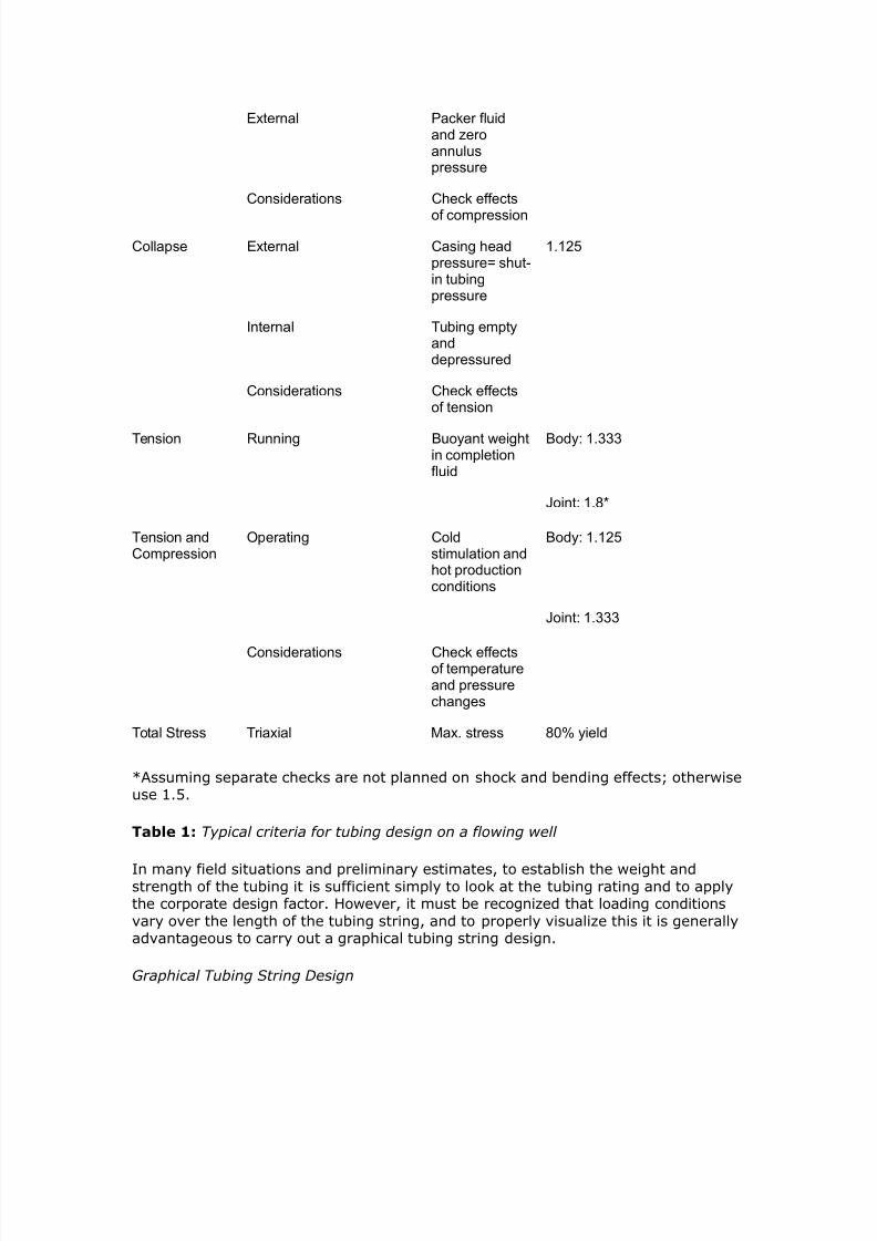
7242019 Completion Equipment
httpslidepdfcomreaderfullcompletion-equipment 584
Figure 3
Abbreiations are resented in the ampomenclature
7242019 Completion Equipment
httpslidepdfcomreaderfullcompletion-equipment 684
Figure 4
Example 2 (part 1
Graphical Tubing Design
lanning Data
KBE ( ft 15 3
$4 115 ft (5 3
$bg 2 67 in 4 6( 3
losed-in bottoholepressure
55 psi ( Pa3
estiated fro ud ampeight
8oration breakdoampn 125 psi 9 Pa3
7242019 Completion Equipment
httpslidepdfcomreaderfullcompletion-equipment 784
pressure
estiated fro offset ampell
8racture propagationpressure
2 psi 9( Pa3
estiated fro offset ampell
Packer fluid inhibited oil ( psi7ft3
Production expect sour gas
gas graity reseroir3
gas graity 6 separator3
)55 or lt tubular to be used
tiulation fracture expected assue 2 barrels per inute3= axiualloampable annulus pressure is 2 psi 1(6 kPa3
T Estimate
Depth ofHole
Gas Gravity
ft $ $amp $ $(
1 (5 6 6 69 6(
2 91 5 59 5( gt9
( 15 ( (5 ( 2
gt 121 2 1gt 6 5
5 152gt 1 ( 5 6
9 1( ( 6( 5gt gt6
6 21(( 9gt 5gt gtgt 2(
2gt( gt6 (5 2( 1
26gt( 2 19 gt 66
1 (gt 12 6 69gt 65
11 ((5( 65 6 699 6(6
12 (99 66 69( 6gt6 616
7242019 Completion Equipment
httpslidepdfcomreaderfullcompletion-equipment 884
1( (92 69( 6gt9 62 96
1gt gt296 6gt6 62 612 96
15 gt562 6(2 61( 95 95
19 gt69 616 96 96 9gt1
16 511 62 92 952 92gt
1 5gt9 96 959 9gt5 96
1 561 96( 952 9(1 5
2 96 95 9(6 915 56gt
Table 2 7atio bet-een surface ressure and bottomhole ressure in gas -ells for a
range of gas graities
t a gas graity I$P 626 IBP ( psi
At a gas grait E 0 ITHP E 0 I2HP E 44 si
8or a kill situation bottohole inAection pressure IBP 2 psi 55 psi 2 psi 65psi
If gas graity $IP 626 BIP 6263 653
E43 si
Assumed Fracture Conditions 1 8oration breakdoampn achieed ampith ampater
ltracture 8ob carried out -ith -aterbase fluid
8riction loss in 2 67 in tubing at 2 BP using ampater ampith friction reducer is (5 psi71 ft for115 ft 4oampell andbook3
8PP 2 psi
ltriction E F40 si (30 )
Head E si (04 00)
ltrac THPE 00 si
Prepare a depth pressure plot 8igure 2 3 in the folloamping anner 1 Plot the closed-in bottohole pressure IBP3
Plot the formation brea6do-n ressure (lt2P) and the fractureroagation ressure (ltPP)
7242019 Completion Equipment
httpslidepdfcomreaderfullcompletion-equipment 984
3 Plot the ac6er fluid gradient fracture fluid gradient and -atergradient
4 gtstimate -et and dr gas gradients and lot these u from the
closedin bottomhole ressure
gtstablish the closedin tubing head ressure for normal roductionconditions (ie oil or as in this case -et gas) and for -orst case
design assumtion (usuall dr gas)
gtstablish ma1imum THP for -hich comletion is to be designed
-hich normall -ill be 6ill or stimulation conditions (fluid gradientthrough lt2P ltPP or secified differential aboe ITHP) ltor gt1amle
the grahical design should no- loo6 li6e ltigure
gtstablish through insection the greatest differential ressure at
surface and do-nhole (usuall stimulation conditions) Getermine -hatstes can be ta6en to reduce loading (eg maintaining ma1imum
allo-able annulus ressure during stimulation) Plot ad8usted annulusressure line ( ltigure 3 )
Plot burst load line (2$$) as difference bet-een most critical tubingand annulus ressures The 2$$ is a function of the relatie densities in
the tubing and annulus 2$$ -ill generall but not al-as decrease-ith deth ( ltigure 3 )
Plot critical collase load conditions ($$) ampormall -e assume thata slo- lea6 has changed the HP to ITHP and that tubing is emt
and deressured This can occur in gas -ells if the tubing becomeslugged or a do-nhole safet ale is closed onditions can aroach
this situation in oil -ells after a fracture treatment if oeratorscommence 6ic6off before bleeding off annulus ressure (In some
cases this ma be a more critical load ( ltigure 4 ))
0 Plot ressure test conditions (PT) This is often the most critical
load to -hich a comletion is sub8ected onsider timing of the
ressure test and densit of fluids in the tubing and annulus at time oftest
$oo6 u tubing erformance data in API 2ulletin
Ad8ust API internal ield (burst) and collase resistancesecifications -ith design factor (see ltigure and API 2ulletin )
3 $ist resulting tubing caabilities ( ltigure 4 )
4 omare design loads -ith tubing caabilities and select tubing In
most cases the otimum tubing grade and -eight -ill ar -ith deth
To minimi+e costs andor tensional loads such ariations ma beincororated although there -ill then be a constraint on ressure
testing caabilities Ho-eer most oerators refer to use a common
7242019 Completion Equipment
httpslidepdfcomreaderfullcompletion-equipment 1084
-eight and grade throughout the comletion if ossible This reducesthe ris6 of installation and oerating errors =hen regulations ermit
the designer ma be able to comromise slightl on accommodatingloading conditions dee in the hole if the associated design
assumtion is e1tremel unrealistic (eg a comletel emt tubing ina high roductiit oil -ell) Ho-eer the designer must first chec6 on
ho- critical the actual bia1ial (or tria1ial) loading conditions are li6elto be and ma6e aroriate notes in the -ell file
Cith reference to Exaple 2 in 8igure gt the options include the folloamping 1 full string of 9gt lb7ft lt tubing
0 to 00 ft E 4 lbft J00 to TG E 4 lbft $0
3 full string of 4 lbft J -ith modified collase design criteria of000 si as ma1imum HP -ith an emt tubing
ince 2 psi is the axiu alloampable annulus pressure during stiulation option ( ay bean acceptable design ince the differential cost of )55 and lt is around D( per ft the potentialsaing of D(gt5 betampeen options 1 and ( ay Austify further detailed engineering ampork n theother hand if the ampellstrea is expected to be extreely corrosie the higher grade tubing aybe selected in any case to proide a corrosion alloampance
The 6e things to note from ltigure (Effect of buoyancy on axial load ) are
bull the ost seere burst loadings occur at surface
7242019 Completion Equipment
httpslidepdfcomreaderfullcompletion-equipment 1184
Figure amp
bull the most seere burst and collase loadings occur during ressure testing
-ell 6ill and stimulation
bull the most seere collase loading occurs do-nhole
bull additional annulus ressure can be used to reduce burst loading roided
the casing is strong enough
bull the tubinghead ressure during 6ill oerations (THIP) often aro1imates or
e1ceeds the reseroir ressure (I2HP)
Cith relatiely sall tubing strings (5 in or 3 the inherent burst and collapse strength isso high that soe engineers do not bother ampith tubing design in ampells ampith depths of less than ft 25 3 unless oerpressures are expected
Simplified Tensional Strength Design
Although burst and collase resistance ma not be significant considerations inuming -ells tensional strength is a critical design arameter for all -ells ouling
lea6age and failure -hich accounts for 0 of the roblems in -ell tubulars often
7242019 Completion Equipment
httpslidepdfcomreaderfullcompletion-equipment 1284
ma be the result of inadeuate tensional design rather than a burst or sealingroblem In this resect it is articularl imortant to remember that test ressures
imose substantial iston forces on the tubing (eg a 000 si (3 Pa) ressuretest on a lug set inside in (3mm) tubing -ill increase the tension on the
hanger b (000)( 4)(44l) E 30 lb (4 6amp)
It is also imortant to recogni+e that unli6e other strength arameters the API 8ointstrength is based on a failure condition rather than the onset of lastic deformation
The failure condition is either an un+iing of the in and bo1 in the case of APIthreads because of ielding (also called 8umout)D or brea6age of reduced cross
section at the threads in the case of suare threads
ltinall there are all sorts of additional tensional loads that -e do not normallanal+e in detail (eg shoc6 loading and drag forces during running bending
stresses buc6ling crosssectional iston forces changes in buoanc)
ince it is common ractice to ma6e a reliminar tensional design using tubing
-eight loading onl a higher design factor is used for tension and eseciall for 8oint
strength (Table 1 aboe) ome comanies and more conseratie engineers -illeen ignore the otential benefits of buoanc 2uoanc results in a iston force onthe lo-er end of the tubing and as a first aro1imation it ma normall be assumed
that
12amphere
CB buoyant ampeight
=amp E -eight in air
E densit of steel ( gmcc)
E densit of fluid
8igure 5 graphically depicts the tensional and copressional forces at ampork on a tapered string of tubular goods $he load resulting fro the ampeight of the pipe is shoampn for a string ampeighed in airand ampith the buoyant forces accounted for as piston forces or approxiated using EFuation 12Ce can see that at a point approxiately idampay in the length of the heaier pipe at the bottoof the string there is a change fro copression to tension $his is also the concept amphich guidesthe design of drillstrings ampith the purpose of keeping the drillpipe in tension amphile using theheaier drill collars to aintain a copressional load on the bit
Part of gt1amle gies the reliminar tension design considerations for thecomletion alread coered in art
Example 2 (part 2
reliminary Tension Design
7242019 Completion Equipment
httpslidepdfcomreaderfullcompletion-equipment 1384
$ubing ampeight 9gt lb7ft
Tubing length 00 ft
Pac6er fluid inhibited oil
03 sift E 0 gmcc
=amp E 4 00E 300 lb
E 0 300
E 04 lb
Joint Specifications
)55 lt
EGE H4 EGE H4 5
PI Aoint strengthKlb3
6 1 1(5 12
4esign factorTable 13
1 1 1 1
4esign capacityKlb3
55gt 559 655 611
Tubing Tension Design Considerations 1 eFuires lt tubing at surface
7euires 8oint strength caabilit of gtKgt or euialent
3 In ie- of ressures deth and H -ould robabl select remium
grade couling
any copanies hae these design techniFues prograed for the coputer and use the saegeneral techniFue for both tubing and casing designs
Tubing Design Parameters
It is imortant to remember that -hile the rimar function of the tubing is as aconduit for hdrocarbon roduction or for in8ection of -ater or gas the most seere
loadings often occur during -ell serice or 6illing oerations or during ressuretests It is therefore rudent to ma6e roision for these oerations -hen designing
a comletion and to chec6 out the tubing limitations -hen lanning a -ell sericingoeration (eg a stimulation or a -or6oer) are must be ta6en not to increase
comletion costs e1cessiel b tring to ma6e roisions for all sorts of unli6el butossible occurrences It must also be remembered that there are stes that can be
7242019 Completion Equipment
httpslidepdfcomreaderfullcompletion-equipment 1484
ta6en to mitigate the induced stresses during man oerations (eg alingannular ressure or heating fracturing fluids) Ln the other hand the conseuential
costs of a failed tubing string or of haing to run a secial -or6ing string in termsof deferred roduction and rig time can be uite substantial Assessment of the
most cost effectie solution is generall a 8udgment call based on the engineer5se1erience and on cororate attitudes and olic A tical set of arameters has
alread been illustrated in gt1amle
urst
The tubing and -ellhead should be designed for suee+e and 6ill conditions incefines in the erforations or oil can sometimes cause a chec6 ale effect -hen
attemting to suee+e bac6 liuids man comletion designers li6e to hae thefle1ibilit of being able to raise the bottomhole ressure to the lt2P or at least to the
ltPP Ho-eer -ith high ermeabilit reseroirs or gas -ells in -hich fracturestimulation is unli6el comletion engineers are often satisfied -ith a certain
minimum differential for in8ection The alue selected aries from area to area andfrom coman to coman but is commonl either around 000 si ( Pa) or 33
of the reseroir ressure The author suggests
1 8BP amphere k1 1 d kg 5 d
ltPP for suee+ing liuids -here 6 00 md
3 I2HP F 000 si ( Pa) for suee+ing gas -here6g 0 mdD or for suee+ing liuids -here 6 000 md
8ro the rock echanics theory presented by eertsa 163 and others it ay be deducedthat in a tectonically relaxed area a proisional estiate of the fracture propagation gradient8P3 can be obtained fro the eFuation
13
ltPM N lt2M N sift ( 6Pam) 1
amphere s oerburden stress J1 psi7ft depth3
E ore ressure si
G E deth ft
ltPM E formation roagation gradient sift
lt2M E formation brea6do-n gradient sift
$he specification of the pressure test conditions is often critical to burst design oernentregulations soeties specify pressure test conditions eg to at least 0 of the reseroirpressure or to 1 psi 5 Pa3 oer the axiu differential pressure expected at the packer3If no regulations exist ost operators test to their tubing design conditions
7242019 Completion Equipment
httpslidepdfcomreaderfullcompletion-equipment 1584
$ollapse
eere collase loads on the tubing can occur
bull in gas ampells and high oil ampells ampith loamp-floamping botto-hole pressures and deep-set safety ales after bloampdoampn to test a plug etc
bull during annulus ressure tests or oeration of shear circulation deices
bull -here there are ressured annuli
bull during underbalance erforating or testing at high dra-do-n
bull during tubing blo-outs
It is iportant to reeber that tension reduces collapse strength $his biaxial effect should beexained for large diaeter tubings especially if reduced collapse design assuptions and7or adeep-set safety ale is used
Tension
Tubing strings are not onl sub8ected to running tensions -ith all the associatedshoc6 and acceleration loadings but also to aring oerating stresses due to iston
forces on the steel andor an lugs ums standing ales and the li6e in thetubing oreoer if the tubing is anchored or held b a ac6er its oerating tension
-ill ar as a result of
bull theral effects hot production or cold kill fluid3
bull iston effects (changes in buoanc and forces at 8oint usets)
bull ballooning effects (changes in internal or e1ternal ressure)
bull buc6ling effects (longitudinal instabilit)
$hese potential probles are listed in ters of their ost coon relatie agnitude althoughthe relatie iportance of piston and ballooning effects is ariable3
$ombined oading
=hile the designer of tubular goods normall tal6s in terms of burst collase and
tension comression as if the -ere indeendent it is obious that in most actualloading situations the occur simultaneousl Precise stress analsis should reallconsider a tria1ial loading situation
The simultaneous solution of all the associated euations is rather comlicated Anumber of comuter rograms are aailable but for most field engineers the -ill be
a blac6 bo1 solution This can be dangerous It is imortant to chec6 that theformulas are roerl handled articularl -ith resect to collase -hich is a
stabilit effect Therefore it is usual for critical stress analses (eg for ultra dee
7242019 Completion Equipment
httpslidepdfcomreaderfullcompletion-equipment 1684
high ressure or sour -ells) to be underta6en b a secialist consultant researchgrou or intracoman tas6 force oreoer since this is not the routine design
techniue design factors are less -ell roen (although a alue of is oftenused)
A more conenient aroach for the intermediate range moderatel comle1 design
roblem is to use the ellise of bia1ial ield stress roosed b Holmuist and ampadai(3) The critical relationshis are (a) tension reduces collase resistanceD (b)comression reduces burst resistance
The other imortant concet in the consideration of tria1ial loads is that ressurechanges affect a1ial stresses or cause tubing moement This has been e1tensiel
discussed in Pgt aers b $ubins6i () Hammerlindl () and tillebroer()
ending
2ending stresses can be significant in large tubulars The are comressie in the
inner -all and tensional in the outer -all the most detrimental being
1ampamphere
the radius of curature ft3
sb E bending stress
gt E Ooung5s modulus (for steel gt E 30 0 si)
do E outside diameter of the tubular
Bending stresses result fro both hole curature and buckling $he effects of doglegs need onlybe considered if they are ery seere 1L71 ft= 1L7( 3 or if ery large tubing 5 172 to 6 in=1gt to 16 3 is being used
Production Casing
The roduction casing must be adeuatel si+ed for the lanned comletion It -illobiousl affect the si+e of the other reuired casing strings the bit selection the
caacit of the rig and the oerall -ell costs The roduction casing must bedesigned for the loads that ma be imosed during the roducing life of the field It
is similar to tubing design in seeral -as
urst
Production casing must be designed to -ithstand the ma1imum closedin tubing
ressure that can be e1ected If a ac6er has been used this ressure is assumed
to be alied at the to of a full column of ac6er fluid (ie for the case of a tubing
7242019 Completion Equipment
httpslidepdfcomreaderfullcompletion-equipment 1784
failure at the surface) =e usuall assume that the e1ternal ressure resisting burstis a -ater gradient If the ac6er fluid is heaier than -ater the burst load -ill
increase -ith deth
In the eent that a snubbing oeration could not be conenientl attemted if atubing brea6 occurs at the surface the casing must be strong enough to -ithstand a
bullhead suee+e on the lie tubing string in -hich case this -ould be the designcriteria for the casing and -ellhead
In man cases it ma be necessar to design the casing for loads imosed during
stimulation and ressure testing onersel the casing caacit must be chec6ed-hen designing a fracturing treatment This is articularl imortant in -ells -here
no ac6er is used
$ollapse
Production casing ma be sub8ect to comlete eacuation during roductionoerations if the -ell is oerated on gas lift or umedoff or if the ac6er or
-or6oer fluid is lost into a deleted +one As the ie ma hae deteriorated beforethis occurs a higher design factor (F) is often used for roduction casing
eere collase loads ma occur in situations in -hich thermal e1ansion of theannular fluid bet-een the roduction and intermediate strings cannot be bled off
(eg in some subsea -ells)
Increased loading should be assumed if lie annuli are a feature of the area 7educed
loadings ma be assumed if the -ells -ill not be umed off gas lifted or seereldeleted
eere collase loads ma e1ist in the a section during high dra-do-n
underbalanced erforating and testing and suee+e either or both cementation andfracturing ( ltigure $ollapse loads in the pay ) It is highl adisable to maintainsome set casingtubing annulus ressure during such serice oerations
7242019 Completion Equipment
httpslidepdfcomreaderfullcompletion-equipment 1884
Figure 1
Tensionamp$ompression
In high rate roduction areas and thermal -ells e1ansion of the roduction tubingma imose additional tension on the casing strings ia the ac6er
$ouplings
In high ressure (000 siD 34 Pa) high temerature (300B ltD 4 ) andor
seerel sour conditions remium casing coulings are recommended
aterial Selection
In sour enironments material secification must consider the chances of Hcontamination of the casingtubing annulus and the added ossibilit of temerature
changes during stimulation affecting the stress corrosion tolerance of the ie
Couplings
There are man forms of couling aailable some of -hich hae been dedicated tothe ublic through the ausices of the API -hile others are roduced b or under
7242019 Completion Equipment
httpslidepdfcomreaderfullcompletion-equipment 1984
license from a secific manufacturer It -as in fact the need to obtain astandardi+ation of thread forms and diameters that led to the formation of the API
ommittee on tandardi+ation of Tubular Moods in 4
The API coulings ( ltigure
Figure 1
ltigure and ltigure 3
7242019 Completion Equipment
httpslidepdfcomreaderfullcompletion-equipment 2084
Figure 2
$utaways of basic types of couplings) are of three basic tes e1ternal uset (gtKgt)
nonuset (ampK) and integral 8oint
7242019 Completion Equipment
httpslidepdfcomreaderfullcompletion-equipment 2184
Figure 3
Threads are of t-o main forms The round API threads are -ea6er than the ie
bod (ie N00 efficient) The buttress threads -ere deeloed b the ampationalTube Giision of the Knited tates teel ororation to roide a high strength
couling for dee high ressure -ell serice This thread is used in a number ofrorietar coulings eg Hdril A Atlas2radford
All taered threads achiee a seal b driing the in and bo1 surfaces together undersufficient stress to generate a bearing ressure e1ceeding an differential that is to
be subseuentl alied Ho-eer a small siral oid is al-as left bet-een themating surfaces and must be filled -ith solids in the form of thread comound (This
is the reason for careful secification of the comound in 2ul A) Ln API roundthreads this oid occurs bet-een the crest and root of the mating threads -hile on
buttress threads it e1tends oer the -hole flan6 of the thread on the beeled side
To imroe lea6 resistance eseciall at eleated temeratures and under high
ressure differential the socalled remium seals -ere deeloed These consist of either metaltometal seals on taered ortions of the in and bo1 surfaces or an
elastomer seal ring or both This te of seal reuires a high ualit finish andrecise gauging and insection The couling is therefore more costl ince API and
7242019 Completion Equipment
httpslidepdfcomreaderfullcompletion-equipment 2284
buttress threads hae roen to be er reliable in the field the decision to use themore e1ensie remium seals reuires careful economic 8ustification In general
their alication has roen aluable in highl corrosie conditions in high ressuregas -ells or high ressurehigh ML7 oil -ells and in thermal -ells sub8ect to high
comressie loads The ma be used -here -or6oer costs are high (egoffshore) In general API tubulars are adeuate for differential ressures of less than
000 si (344 Pa) and temeratures of less than 300B lt (0B ) using hightemerature thread comound ltor corrosie conditions and continuous gas sericethe ressure limit is often reduced to 00 si ( Pa)
gt1ercises
)ilfield nits
The in 4 lbft J ampK tubing string in a 000ft oil -ell -as designed
based on the tubing5s buoant -eight in -ater =hat additional load -ould beimosed on the tubing if a rod um -ere to be ressure tested to 00 si after the
-ell had been oerating for some time and the annulus umed offQ The -ell
roduces 30B API oil (M 0) -ith no -ater
If coman olic dictates the use of a design factor of for 8oint strength can
this ressure test be safel carried outQ
SI nits
The 3mm ( in) 6gmm (4 lbft) J ampK tubing string in an 30moil -ell -as designed based on the tubing5s buoant -eight in -ater =hat additional
load is imosed on the tubing if a rod um -ere to be ressure tested to 3 Paafter the -ell had been oerating for some time and the annulus umed offQ The
-ell roduces 6gm3 oil (M 0) -ith no -ater
If coman olic dictates the use of a design factor of for 8oint strength can
this ressure test be safel carried outQ
olutions
)ilfield nits
=eight in air E 000 ft 1 4 E 3400 lb
2uoanc in -ater E E 0
(densit of -ater gmccD densit of steel E gmccD use gtuation )
12
7242019 Completion Equipment
httpslidepdfcomreaderfullcompletion-equipment 2384
Buoyant ampeight amphen run (gt x 65 ((9 lb
=ater gradient (M E ) E 0433 sift
Lil gradient (M E 0) E 0 1 0433 E 03 sift
IG of tubing E 44 in Ai E 40 in
=eight of oil in tubing E 000 1 03 1 40 E 04 lb
Total alied tensile force at the surface after -ell has been umed off euals
Ceight of oil ampeight of tubing in dry casing applied pressure x area of tubing I4 19gt2 (gt 5 gt93 19gt2 (gt 2(gt 51(2 lb
The API 8oint strength rating of in 4 lbft J nonuset tubing E 00lb
If a design factor of for 8oint strength is dictated b coman olic the
allo-able tensile loading (-ith design factor) E (00) ()E 4400 lb
Therefore the roosed loading e1ceeds the design secifications and a lea6 mightoccur during the test In fact the loading e1ceeds design secs een -ithout adding
the 00 si of -ellhead ressure (actual load 404 lb comared -ith an allo-ableof 4400 lb) Ho-eer using a 33 design factor for oerating loading conditions
ressure tests of u to 4 si -ould be ermissible
6293 1((3 19gt2 (gt pt gt93
Pt E 4 si
+ nits Ceight in air 1( x 5 16(5 kg 165 kM
2uoanc factor in -ater E E 0
(densit of -ater E gmccD densit of steel E gmccD use gtuation )
12Buoyant ampeight amphen run 165 x 65 1gt2 kM
=ater gradient (M E 0) E 4 6PamLil gradient (M E 0) 0 1 4 E 6Pam
7242019 Completion Equipment
httpslidepdfcomreaderfullcompletion-equipment 2484
IG of tubing E mm thus Ai E 30 1 l04 m
=eight of oil in tubing E (30 m) ( 6Pam) (30 1 03 m)E 44 6amp
Total alied tensile force at the surface after -ell had been umed off euals
Ceight of oil ampeight of tubing in dry casing applied pressure x area of tubing I4 gt6gt 165 (5 (1 x 1 -(3 gt6gt 165 156 22gt6 kM
8ro 8igure 1 the PI Aoint strength rating of 6(- 5 kg7 )-55 nonupset tubing is
629 lbs (222 kM3
Figure 1
If a design factor of for 8oint strength is dictated b coman olic the
allo-able tensile loading (-ith design factor)
(222715 2152 kM
7242019 Completion Equipment
httpslidepdfcomreaderfullcompletion-equipment 2584
$herefore the proposed loading exceeds the design specifications and a leak ight occur duringthe test In fact the loading exceeds design specifications een at ero ampellhead pressure actualload of gt6gt 165 216 kM copared ampith an alloampable load of 2152 kM3
Ho-eer using the 33 design factor for oerating loading conditions ressure tests
of u to 6Pa -ould be ermissible
216 pt (1 x l-gt3
t E 4 6Pa
2 )ilfield nits 12-ft hydrostatically pressured gas ampell γ g 63 is to be copleted Chat closed-in tubing
head pressure can be expectedN If the casing ampellhead and tubing are to be designed for asFueee kill at fracture propagation pressure 8PP3 amphat ampellhead pressure ampould be expected atthe start of the kill operationN Gse EFuation 1( for estiating the 8P3
13
+ units (99- hydrostatically pressured gas ampell γ g 63 is to be copleted Chat closed-in tubinghead pressure is expectedN
If the casing -ellhead and tubing are to be designed for a suee+e 6ill at fractureroagation ressure (ltPP) -hat -ellhead ressure -ould be e1ected at the start
of the 6ill oerationQ (Kse gtuation 3 for estimating the ltPM)
olutions
)ilfield nits
Condition Loading Design Criteria Typical Design Factor
Burst Internal Kill pressure on
hydrocarbon-filled tubing
1125
External Packer fluid and eroannulus pressure
onsiderations heck effects ofcopression
ollapse External asing head pressure 1125
7242019 Completion Equipment
httpslidepdfcomreaderfullcompletion-equipment 2684
shut-in tubing pressure
Internal $ubing epty anddepressured
onsiderations heck effects of tension
$ension unning Buoyant ampeight in Body 1(((
copletion fluid )oint 1+
$ension andopression
perating old stiulation and hotproduction conditions
Body 1125
)oint 1(((
onsiderations heck effects ofteperature andpressure changes
$otal tress $riaxial ax stress 0 yield
CAssuming searate chec6s are not lanned on shoc6 and bending effectsD other-iseuse
Table 1 Typical criteria for tubing design on a flowing well
The ratio of THP to 2HP for γ g of 0 E 04
At 000 ft assuming a hdrostatic gradient of 0433 sift the bottomholeressure can be estimated as
BP 12 x gt(( 519 psiampith gas surface pressure 519 x 6gt6 I$P (1 psi
Assuming the oerburden gradient to be sift and using gtuation 3 to estimate
the fracture roagation ressure
E 0 sift
ltPP E 0 000 ft E 04 si
axiu ampellhead pressure at the start of the kill operation $IP3 ampill eFual the forationpropagation pressure inus the pressure due to the gas gradient
7242019 Completion Equipment
httpslidepdfcomreaderfullcompletion-equipment 2784
$IP 12 6163 - 519 - (13 62 psigore correctly ampe should use the ratio in Table 1 since the increased pressure ampill increase thegas density
$IP 12 6163 6gt6 9gt26 psi$herefore a 5 psi ampellhead should not be used een though the axiu closed-in tubinghead pressure is only about gt psi
SI nits
7eferring to Table 1
The ratio of THP to 2HP for γ g E 0 E 04
At 30 m assuming a normal hdrostatic ressure of 6Pa m bottomholeressure can be estimated as
BP (99 65 (55 kPa
ampith gas surface pressure (55 6gt6 I$P 296 kPa
Assuming the oerburden gradient to be 6Pam and using gtuation 3 toestimate the fracture roagation ressure
E 6Pam
ltPP E 30 E 3 6Pa
axiu ampellhead pressure at the start of the kill operation $IP3 ampill eFual the foration propagation pressure inus the pressure due tothe gas gradient
THIP E (30 ) (30 0) E 0 6Pa
ore correctly ampe should use the ratio in Table 1 since the increased pressure ampill increase thegas density
$IP (99 19213 6gt6 gtgt(1 kPa
9gt Pa ampellhead should therefore be used
3hellip)ilfield nits
A 000ft -ell that is to be roduced -ith a target of 000 T2d using intubing encounters 0 ft of oilbearing formation -ith a ressure of 3000 si =hat
rating of -ellhead should be usedQ If a single grade and -eight of tubing is to be
7242019 Completion Equipment
httpslidepdfcomreaderfullcompletion-equipment 2884
used -hat is the cheaest string that can robabl be run assuming that
Grade -eight lbft
Collapse
+trength psi
urst
+trength psi
Tensional
+trength 1 lb
Cost Coparison
)-55 155 gtgt gt1 ( cheapest
16 gt1 5(2 (2
-65 16 96 625 gt2( ost expensie
M- 16 92 66gt gtgt9 oderately expensie
2 ( 52gt
ac6er fluid inhibited sea-ater (gradient E 043 sift)
reseroir ressure 3000 si
6ill ressure 000 si aboe I2HP (suee+ing gas)N fracture roagation ressure (suee+ing oil)
ltracture roagation ressure gradient (ltPM) is aro1imatel
8P 5 5 psi7ft3
If gas cap gas should break through into the ampell assue gas graity 95
Kse Table 1 to calculate head of gas
Condition Loading Design Criteria Typical Design Factor
Burst Internal Kill pressure onhydrocarbon- filledtubing
1125
External Packer fluid and ero
annulus pressure
onsiderations heck effects ofcopression
ollapse External asing head pressureshut-in tubing pressure
1125
Internal $ubing epty and
7242019 Completion Equipment
httpslidepdfcomreaderfullcompletion-equipment 2984
depressured
onsiderations heck effects of tension
$ension unning Buoyant ampeight incopletion fluid
Body 1((( )oint 1+
$ension andopression
perating old stiulation and hotproduction conditions
Body 1125)oint 1(((
onsiderations heck effects ofteperature andpressure changes
$otal tress $riaxial ax stress 0 yield
CAssuming searate chec6s are not lanned on shoc6 and bending effectsD other-iseuse
Table 1 Typical criteria for tubing design on a flowing well
Assume lie oil gradient is 03 sift
onsider onl the ma1imum burst at the -ellhead the ma1imum collase load at theac6er and the running tension
SI nits
A 30m -ell that is to be roduced -ith a target of 400 m3da of oil -ith l40mm ( inch) tubing encounters 0 m of oilbearing formation -ith a ressure of
000 6Pa =hat rating of -ellhead should be usedQ If a single grade and -eight oftubing is to be used -hat is the cheaest string that can robabl be run assuming
that
Grade -eight
$gmm
Collapse
+trength
$Pa
urst
+trength
$Pa
Tensional
+trength
$amp
Cost Coparison
)-55 2(1 2655 ((19gt 1((gt cheapest
25( ((5( (99 1gt9(
-65 25( gt151 gt6 12 ost expensie
M- 25( gt(2 5((95 1gt oderately expensie
2 9 91gt 2((1
7242019 Completion Equipment
httpslidepdfcomreaderfullcompletion-equipment 3084
ac6er fluid inhibited sea-ater (gradient E 40 6Pam)
reseroir ressure 000 6Pa
6ill ressure 000 6Pa aboe I2HP (suee+ing gas)N fracture roagation ressure (suee+ing oil)
ltracture roagation ressure gradient (ltPM) is aro1imatel
8P 53 22(3 5 kPa7If gas cap gas should break through into the ampell assue gas graity 95
Kse Table 1 to calculate head of gas
Assume lie oil gradient is 6Pam
onsider onl the ma1imum burst at the -ellhead the ma1imum collase load at the
ac6er and the running tensions
olution
)ilfield nits
I$P IBP - o 4
o ( psi7ft
under operating conditions I$P ( - ( 63 psi
under axiu conditions assuing gas breakthrough3
ITHP E 04 1 2HP (from Table 1)
AR ITHP E 04 1 3000 E si
under 6ill conditions
8P 5 5
5 5 x 61 psi7ft
ltPP E 000 0
E 000 si
7242019 Completion Equipment
httpslidepdfcomreaderfullcompletion-equipment 3184
O BIP oil kill3
5 psieFuialent $P oil kill3
5 - ( x 6 2 psi
In the case of a gas kill
Iamp 2HIP(gas 6ill)
( 1 psi gt psi
eFuialent $P gas kill3
5gt x BP 5gt x gt (gt19 psi
8ro this ampe see that amphile ampe could probably get aampay ampith a ( psi ampellhead strictlyspeaking ampe should be using a 5 psi ampellhead
Incororation of the roision in some regulations for a -ellhead rating euialent
to the reseroir ressure reflects this tical design for 6ill caabilit
Tubing urst (ating
burst rating E ma1 THP design factor
design factor E
reuired burst rating (for gas 6ill conditions) E 34 E 343 si
All grades and -eights satisfactor
Tubing Collapse )oading Calculation
alculate first assuming a high ris6 of gas brea6through
head of packer fluid f 3 43 gt(53 63 (gt5 psi
ma1 HP E ma1 ITHP (assumes lea6)E si
ma1 2H annulus ressure E F 304E 0 si
7242019 Completion Equipment
httpslidepdfcomreaderfullcompletion-equipment 3284
ma1 collase load E 0 0 si (assumes emt tubing)E 0 si
design factor E
reuired collase rating E 0 1 si
E 30 si
$herefore strictly speaking ampe should use 2-lb7ft M- tubing although it is ore likely a l6-lb7ft ampould be selected since the probability is ery loamp that such seere collapse-loadingassuptions ampould proe true
alculate ne1t assuming a lo- ris6 of gas brea6through
ax P operating I$P
oerating ITHP E 00 si
ma1 2H annulus ressure E 00 F 304 siE 34 si
ma1 collase load E 34 si
reuired collase rating E 34 E 443 si
Ce could select 16 lb7ft )-55 tubing
(unning Tension Calculations
ampeight in air C 4 16 lb7ft3 6 ft3 11 lb
buoyancy factor
625
buoant -eight of tubing E 0 000 lb
E 04000 lb
design factor E
reuired tension rating E (04000) () lb
16 lb$his can be easily carried by any of the tubing grades listed
7242019 Completion Equipment
httpslidepdfcomreaderfullcompletion-equipment 3384
It is tical for collase design to be the critical factor in highrate largetubingcomletions eseciall at relatiel shallo- deths
Conclusion
in 0lbft amp0 tubing meets all criteria for this te of roduction 7is6 of
gas brea6through must be accuratel assessed before choosing bet-een amp0 and J grades
SI nits
I$P IBP - ρo x 4
ρo 969 kPa7
under operating conditions I$P 26 - 969 x 21(3
92gt9 kPaunder axiu conditions gas breakthrough3
ITHP E 04 1 2HP (from Table 1)
AR ITHP E 04 1 000 E 6Pa
under 6ill conditions
8P 53 22(3 5
53 22(3 5
19 kPa7
ltPP E (30) (00)
E 3400 6Pa
O BIP oil kill3 (gt kPa eFuialent $P oil kill3 (gt - 969 x 21(3
1929 kPa
In the case of a gas 6ill
Iamp 2HIP
(gas 6ill) E 000 F 000 6Pa
266 kPaeFuialent $P gas kill3 5gt x BP
5gt x 266 2(959 kPa
8ro this ampe see that amphile ampe could probably get aampay ampith a 26 Pa ampellhead strictlyspeaking ampe should be using a (gt5 Pa ampellhead
7242019 Completion Equipment
httpslidepdfcomreaderfullcompletion-equipment 3484
Incororation of the roision in some regulations for a -ellhead rating euialentto the reseroir ressure reflects this tical design for 6ill caabilit
Tubing urst (ating Calculation
burst rating E ma1 THP 1 design factor
design factor E
reuired burst rating (for gas 6ill conditions) E 3 1
E 3 6Pa
All grades and -eights satisfactor
Tubing Collapse )oading
alculate first assuming high ris6 of gas brea6through
head of packer fluid ρf 3 43
gt3 21(3 25 kPa
ax P ax I$P assues leak3 1696 kPa
ma1 2H annulus ressure E F 0
E 33 6Pa
ma1 collase load E 33 0 6Pa (assumes emt tubing)
E 33 6Pa
design factor E
reuired collase rating E 33 1 E 434 6Pa
Therefore strictl sea6ing -e should use a 6gm amp0 tubing but moreli6el 36gm tubing -ould be selected since the robabilit of such seere
collase loading is er lo-
alculate ne1t assuming lo- ris6 of gas brea6through
ax P operating I$P
oerating ITHP E 4 6Pa
ma1 2H annulus ressure E 4 F 0
E 0 6Pa
ma1 collase load E 0 6Pa
7242019 Completion Equipment
httpslidepdfcomreaderfullcompletion-equipment 3584
reuired collase rating E 0 1 E 300 6Pa
Ce could select 25(-kg7 )-55 tubing
(unning Tension Calculation
ampeight in air 25( 21( 5( kg 525 kM
buoanc factor E
EE0
buoant -eight of tubing E 0 6ampE 4 6amp
design factor E
reuired tension rating E (4) ()
E 30 6amp
$his can be easily carried by any of the tubing grades listed
It is tical for collase design to be the critical factor in highrate largetubing
comletions eseciall at relatiel shallo- deths
Conclusion
40mm ( inch) 36gm 0 tubing meets all criteria for this te ofroduction 7is6 of gas brea6through must be accuratel assessed before choosing
bet-een 0 and J grades
Pac6ers
Pac$er unctions
A ac6er is a subsurface tool that roides a seal bet-een the tubing and
casingthereb reenting the ertical moement of fluids across this sealing oint
Pac6ers are used for the follo-ing reasons
9 to imroe safet b roiding a barrier to flo- through the annulus
7242019 Completion Equipment
httpslidepdfcomreaderfullcompletion-equipment 3684
9 to 6ee -ell fluids and ressures isolated from the casing
9 to imroe flo- conditions and reent heading
9 to searate +ones in the same -ellbore
9 to lace 6ill fluids or treating fluids in the casing annulus
9 to ac6 off erforations rather than use suee+e cementing
9 to 6ee gas lift or hdraulic o-er fluid in8ection ressure isolated from the
formation
9 to anchor the tubing
9 to install a casing um
9 to minimi+e heat losses b allo-ing the use of an emt annulus or thermal
insulator
9 to isolate a casing lea6 or lea6ing liner la
9 to facilitate temorar -ell serice oerations (eg stimulations suee+es)
Pac$er T+pes
There are man ac6er manufacturers some of -hom offer an e1tensie ariet ofac6ers -ith each differing to some degree from those of the other manufacturers
This rather be-ildering arra can ho-eer be groued into rincial classes or
tes and ma be further categori+ed b method of setting b direction of ressureacross the ac6er and b the number of bores through the ac6er
Pac6ers can be rimaril classified as either retrieable or ermanent or
ermanentretrieable or inflatable
)etrievable acers
This te of ac6er is run on the tubing ( ltigure )etrievable pacer )
7242019 Completion Equipment
httpslidepdfcomreaderfullcompletion-equipment 3784
Figure 1
After setting it can be released and recoered from the -ell on the tubing ince it is
an integral art of the tubing string the tubing cannot be remoed from the -ell-ithout ulling the ac6er unless a detachable ac6er head is used
7etrieable ac6ers ma be designed to be set mechanicall or hdraulicallechanical setting methods include rotation of the tubing string recirocation of the
tubing string or the alication of tension or setdo-n -eight =ith mechanical
ac6ers the tubing is usuall set in comression
Hdraulic ac6ers are set b aling hdraulic ressure through the tubing stringbut once set the hold the set osition mechanicall The tubing is usuall in tension
7etrieable ac6ers are usuall used for comle1 multi+one and multistringcomletions Their main limitation -as in their limited abilit to accommodate tubing
stress changes -ithout unsettingD the aailabilit of effectie sli 8oints anddetachable heads has eased this situation An historical roblem -as failure of the
internal elastomer seals but this technolog also has imroed mar6edl in the lastdecade All metaltometal seal ac6ers are aailable but are e1ensie
7242019 Completion Equipment
httpslidepdfcomreaderfullcompletion-equipment 3884
Lne disadantage of retrieable ac6ers is that if the fail to retriee the must beremoed b milling them out of the casing -ith an abrasie milling head and a
drillstring The are er difficult to mill Menerall this te of ac6er is used undernonseere conditions (differential ressures less than 000 si (344 Pa)
temeratures less than 300B lt (4B )
2ecause of the setting mechanism retrieable ac6ers tend to hae a restrictedbore comared -ith other ac6ers designed for the same casing si+e This factorma restrict flo- or limit -ireline oerations belo- the ac6er deth
ermanent acers
Permanent ac6ers are indeendent of the tubing and ma be run on tubing or on
-ireline ( ltigure and ltigure 3 )
Figure 2
The tubing can be released from the ac6er and can be ulled leaing the ac6er set
in the casing
7242019 Completion Equipment
httpslidepdfcomreaderfullcompletion-equipment 3984
Figure 3
Tubing can subseuentl be run bac6 and resealed in the ac6er The ac6er ma
thus be considered an integral art of the casing It is sometimes called either aroduction ac6er or a retainerroduction ac6er
The ermanent ac6er cannot be recoered as such but it can be destructiel
remoed (eg b milling) ( ltigure 4 and ltigure )
7242019 Completion Equipment
httpslidepdfcomreaderfullcompletion-equipment 4084
Figure 4
If the ac6er includes a tailie and must be recoered a millout e1tension is
needed on the ac6er for the ac6er ic6er or catch sleee on the mill to engageIn other cases it ma be adeuate to siml ush the ac6er to the bottom of the
casing after milling
7242019 Completion Equipment
httpslidepdfcomreaderfullcompletion-equipment 4184
Figure amp
Permanent ac6ers can be set using an electric -ireline setting tool a hdraulicsetting tool run on drillie or tubing or b a combination of rotation and ull
Permanent ac6ers are ticall used -hen
9 formation treating or s-abbing differential ressures -ill be high
9 it is desirable to ull the tubing -ithout unseating the ac6er
9 it might be desirable to conert the ac6er to a temorar or ermanentbridge lug
9 high bottomhole temeratures e1ist
9 tubing oerating stress ariations -ould not be accommodated -ith a
retrieable ac6er -ithout ma6ing it imossible to ull
9 a retrieable ac6er -ould hae an inadeuate bore
ermanent+)etrievable acers
7242019 Completion Equipment
httpslidepdfcomreaderfullcompletion-equipment 4284
A recent arrial this te of ac6er has the same characteristics as the ermanentac6er but it can -hen desired be released -ith a secial ulling tool and
recoered
nflatable acers
These are ac6ers -ith a fle1ible sealing element that can be e1anded hdraulicallusing either comletion fluid or cement The are used as oenhole ac6ers or -hen
the casing is buc6led or collased reenting the usage of conentional ac6ers
Inflatable ac6ers cannot stand high ressure differentials and are generall limited
to secial alications such as drillstem testing
acer -ailures
The ma8or causes of socalled ac6er failures relate to
9 use of the ac6er outside its oerating range
9 unsetting of the ac6er or seal assembl as a result of ressure ortemerature changes
9 using or setting the ac6er incorrectl
9 the ac6er being in oor condition -hen run
Gifficult oerating conditions reuire more e1ensie euiment and more rigorous
design -or6 It is imortant to remember that a ac6er is effectiel a iston -ithin
the casing and -ill therefore be heail affected b changes in differential ressurePressure from belo- or increasing string tension due to tubing contraction or both
tend to unset the follo-ing
9 -eightset ac6ers
9 hdraulicall set ac6ers not euied -ith holddo-n buttons
9 locator seal assemblies or oershots
Pressure from aboe tends to unset tensionset ac6ers or cause collasete
failures or lea6age at seal assemblies under high ressure differentials
Tubing0acer Forces and oveent
hanges in temerature and ressure inside and outside the tubing affect the lengthof the tubing string (if the string is designed to ermit motion) and the forces
e1erted at the ac6er (if no motion is ermitted)
These changes in tubing length or force bet-een roducing and umin conditions
can be large and should be considered in choosing a ac6er This is eseciallimortant in high temerature (usuall dee) -ells and ma limit the use of
7242019 Completion Equipment
httpslidepdfcomreaderfullcompletion-equipment 4384
retrieable ac6ers Gesign of sli 8oints and seal assemblies must also considerthese forces
(The follo-ing section dra-s heail on the -or6 of GJ Hammerlindl () and
Arco as ublished in T ltebruar and on that of Arthur $ubins6i = Althouse and T $ $ogan ())
actors Causing Pac$er orces or Tubing o-ement
If the tubing string is free to moe its length -ill change as a result of temeratureand ressure influences -hich ma be subdiided into thermal iston force
ballooning and buc6ling effects onsideration of these effects -ill determine theseal length reuired andor sli 8oint design
If the tubing is anchored to the ac6er these effects -ill result in a change In thea1ial tension in the tubing This can affect not onl the design of the uermost
tubing 8oint but also ac6er shear in rating and the degree of buc6ling aboe theac6er and therefore the throughbore access A mechanical force is also inoled in
this situation
To consider these effects it is necessar to define the critical conditions to be
e1amined These normall include
bull landing conditions=
bull oerating conditionsD
bull shutin conditionsD
bull 6illingstimulating conditionsD
bull ressure test conditions
Initial calculations are ade for a set of assued landing conditions eg -5 to 5 lb -225 to 225 kM3 tension -3 or copression 3 8or conenience adesigner ay soeties choose to exaine only the differences betampeen amphat are considered tobe the ost seere conditions ie hot producing to cold stiulating3= hoampeer these are notalampays apparent eg pressure test loads can be the ost seere3
ecanical orces
echanical forces can be subdiided into tension and comression Tension results in
the stretching of tubing string The elongation due to tension forces can bedetermined b Hoo6e5s la- -hich states that the change in length is directl
roortional to the alied force The euation for Hoo6e5s la- in this alication isas follo-s
1amphere
7242019 Completion Equipment
httpslidepdfcomreaderfullcompletion-equipment 4484
length change inches3 lt tubing length inches3 8t tensional force -3 lbf3 E HoungQs odulus ( 19 psi3
s cross-sectional area of the tubing ampall in23$his relationship is the basis of the tubing stretch tables and graphs published by arious
eFuipent anufacturers
Temperature or Termal Effects
The length change due to change in temerature is eual to the length of the tubing
times the coefficient of thermal e1ansion for steel times the change in aeragetemerature
ince
1then
1(amphere
change in tensional force in tubing at the surface due to teperaturechange
s the coefficient of theral expansion for steel β3 is 9 l-97L8 12gt2 l-97L3 and HoungQsodulus E3 is ( x 19 psi 26 Pa3
-26 s ∆$ lb7L8
ltt E As ∆T ampB
In ost cases it is adeFuate to deal ampith the change in the aerage string teperature It is oftenassued that
bull the copletion is at geotheral gradient amphen landed 1 to 2L 871 ft or 1 to (9L71 3
bull during stimulation6illing it -ill stabili+e -ithin 0B lt (0B ) of ambient
temerature
$he teperature during producing conditions is a function of floamp rate gas expansiongeotheral gradient theral insulation of the tubing and the like Rarious coputer prograsare aailable to calculate this in critical cases but it is usually adeFuate to use data fro offsets
producing under siilar conditions Production test data should be used Audiciously since testrates and floamp periods are often too loamp and too short for theral stabiliation to occur s a firstapproxiation designers ampill often assue a floamping gradient for high rate ampells of gt L871 ftor 6 L71
Piston orce Effects
The most familiar form of iston force is that of the stretch andor stress induced
-hen ma6ing an internal ressure test against a lug set inside a string of tubing
7242019 Completion Equipment
httpslidepdfcomreaderfullcompletion-equipment 4584
The force against the lug is eual to the ressure alied times the crosssectionalarea of the tubing IG
8p pt i 18or exaple a 1 psi 9 kPa3 pressure test on ( 172-in 3 tubing I4 22 in3should result in a force of
8p 1 2232 6 lb (11 M3
Chere the tubing is inserted into a packer ampe ust siilarly consider the piston effects on thecross section of the steel as it is affected by changes in the internal and external pressure
The iston force at the ac6er related to a change in the inside and outside ressures
is
8p p - i3 pi - p - o3 po 2amphere
p area of packer bore
Ai E area of tubing IG
Ao E area of tubing LG
$he change in tubing length related to this piston force is
21
amphere the pi and ∆po changes are considered positie if they correspond to an increase andnegatie if they correspond to a decrease in pressure 8igure 1 Schematic showing piston force
at the packer related to a change in the inside and outside pressures3
7242019 Completion Equipment
httpslidepdfcomreaderfullcompletion-equipment 4684
Figure 1
The iston forces are in essence the change in the buoant force on the tubing
allooning Effects
As the ressure inside the tubing increases the ie e1ands radiall This -ill cause
an a1ial shortening Alication of ressure to the annulus -ill cause the tubingdiameter to contract (reerse ballooning) This -ill result in a tubing elongation
The length change accounts for the change in radial ressure forces due to surface
ressure changes (∆is and ∆os) and fluid densit changes (∆ρi and ∆ρo) as -ell as
flo- inside the tubing (δ ) The formula for calculating the change in length due to
ballooning is
7242019 Completion Equipment
httpslidepdfcomreaderfullcompletion-equipment 4784
22amphere
PoissonQs ratio of the aterial for steel (3
7 E ratio LGIG of the tubing
δ E dro in ressure in the tubing er unit length due to flo- The
ressure dro is ositie -hen the flo- is do-n-ard and +ero -henthere is no flo-
ρi E densit of fluid inside tubing
ρo E densit of fluid outside tubing
is E surface tubing ressure
os E surface annulus ressure
ucling ffects
2uc6ling is caused b t-o effects alied longitudinal comression loads andinternal ressure
The first is eas to understand as a logical conseuence of the loading of a columnHo-eer the buc6ling of a ie under tension as a result of internal ressure is a
difficult concet to areciate Lne -a to isuali+e this te of buc6ling is toconsider a slightl bananashaed tubing 8oint sub8ect to internal ressure ( ltigure
and ltigure 3 $auses of bucling)
Figure 2
7242019 Completion Equipment
httpslidepdfcomreaderfullcompletion-equipment 4884
There -ill be a small unoosed area uon -hich the ressure -ill act to cause
distortion of the ie
Figure 3
The resulting buc6ling -ill reflect the balance of strain and bending energ This issimilar to haing a fictitious force (ltf ) acting on the end of the ie
To better understand buc6ling resulting from comression loading consider a stringof tubing freel susended inside the casing ampo- consider an u-ard force lt
alied to the lo-er end of the tubing This force comresses the string and buc6lesthe lo-er ortion of the string into a heli1 The neutral oint is -here the buc6ling
stos This force decreases -ith increasing distance from the bottom of the string
and becomes +ero at the neutral oint The distance n from the bottom of thetubing to the neutral oint is calculated from the follo-ing formula
23amphere
C Cs ρi i - ρo o representing the buoyed ampeight of the tubing per unit length 8 the force applied to the loamper end
It should be understood that in the presence of fluids the neutral point is not the point at amphichthere is neither tension nor copression but it is the point beloamp amphich the string is buckled andaboe amphich the string is straight
7242019 Completion Equipment
httpslidepdfcomreaderfullcompletion-equipment 4984
If the neutral oint is -ithin the string then the shortening of the string due to
buc6ling (∆$b) is as follo-s
24amphere I is the oent of inertia of tubing cross section ampith respect to its diaeter
I E (G4 d4)
=hen the calculated alue of the neutral oint is aboe the uer end of the string
the entire string buc6les into a heli1
=hen the ressure inside the tubing (P i) is greater than the ressure outside (o) at
the ac6er a shortening -ill occur due to helical buc6ling It -as determined b
$ubins6i Althouse and $ogan () that as far as the buc6ling is concerned thetubing behaes as if sub8ect to the follo-ing fictitious force
8f ppi - po3 2ampBecause part of this force 8f appears to be nonexistent the entire force 8 ampas gien the naefictitious 8urther it ampas deterined that the string ampould buckle if 8f is positie and ampould reainstraight if 8f is ero or negatie ubstitution into EFuation 2gt gies
2
amphere ∆ltb is the change in length ampith respect to the length of the tubing amphen landed ampith p i po
If the ressure outside the tubing is greater than the ressure inside the tubing atthe ac6er (o i) there is no helical buc6ling due to ressure
The total change in tubing length as a result of these arious factors (mechanical andiston forces and thermal ballooning and buc6ling effects) ma be e1ressed as
lt lt ltt ltp ltB ltb 2
$he effect of this net change in tubing length on the tubing stress ampill depend upon the aount ofotion peritted by the packer design
Permanent Cor$screing
If the buc6ling results in the ield strength of the tubing being e1ceeded ermanentcor6scre-ing can occur In addition to the stresses of helical buc6ling the tubing issub8ect to elongational stresses as -ell as tangential and radial stresses due to
ressure inside and outside the tubing A tria1ial stress analsis must be made -hereconditions suggest that significant tubing stress -ill result All the ma8or euiment
suliers hae comuter and hand calculator rograms aailable for ma6ing thesecomutations This serice is usuall aailable free to urchasers The roduction
engineer should send some time determining the ressure and temeratureconditions to be e1ected Ticall a series of calculations is made for arious
7242019 Completion Equipment
httpslidepdfcomreaderfullcompletion-equipment 5084
landing assumtions and the results lotted for analsis It is also useful to ma6e atleast one hand calculation as a crosschec6 on the data receied
gt1ercise
1 )ilfield nits
A 0000ft highrate oil -ell is comleted -ith in lbft tubing (-allthic6ness 0 in) Knder roducing conditions the flo-ing temerature gradient is
04 Bltl00 ft and under static conditions the geothermal gradient is Blt00 ftfrom a mean surface temerature of 40 Blt =hen the -ell is 6illed -ith a large
olume of 40 Blt sea-ater the bottomhole temerature dros to 0 Blt If free tomoe -hat tubing moement can be e1ected from the landing condition to the hot
roducing and to the cold in8ection conditionsQ If a hdraulic ac6er -ere to be usedand set in 30000 lb of tension -hat -ould be the tension loading on the ac6er
after 6illing the -ellQ (Kse gtuation and ignore iston ballooning and buc6lingeffects)
1(
+ nits
A 300m highrate oil -ell is comleted -ith 40mm 36gmm tubing (-allthic6ness E mm) Knder roducing conditions the flo-ing temerature gradient is
03 B00 m and under static conditions the geothermal gradient is 3 Bl00 mfor a mean surface temerature of 0 B =hen the -ell is 6illed -ith a large
olume of 0 B sea-ater the bottomhole temerature dros to 0 B If free tomoe -hat tubing moement can be e1ected from the loading condition to the hot
roducing and to the cold in8ection conditionsQ If a hdraulic ac6er -ere to be usedand set in 334 6amp tension -hat -ould the tension loading on the ac6er be after
6illing the -ellQ
(Kse gtuation and ignore iston ballooning and buc6ling effects)
olution
)ilfield nits
7eseroir temerature E 40 F ( 1 0000 S 00) E 0 Blt
Temerature loss u the tubing E 04 1 0000 S 00 E 40 Blt
ltlo-ing tubing head temerature E 0 40 E 0olt
ltrom landing conditions to roducing conditions
7242019 Completion Equipment
httpslidepdfcomreaderfullcompletion-equipment 5184
ltt lt3 β 3 $3
13 9 1-93 $3
amphere $
$anding E 30Blt
Producing E 00Blt
$ 2 - 1( 6L8
$t E (0000) ( 1 0) (0) E F43 ft
amphere 1 initial aerage teperature in tubing string
2 final aerage teperature in tubing string $surf surface tubing string teperature $B bottohole tubing string teperature
8ro producing to inAection conditions
Producing E 00 Blt
In8ection E Blt
$ 55 - 2 -1gt5L8
ltt lt3 β 3 $3 13 9 1-93 -1gt53 -1 ft
$herefore the axiu oerall length change is -1 ft fro producing to inAection
gtuation states the change in tension to be
8t -Eβ 3 s3 $3for tubing ampith 4 55 in and I4 gt5 in
gt51 in2
Betampeen landing and inAecting conditions the apparent force acting on the tubing to cause thecontraction effect is
7242019 Completion Equipment
httpslidepdfcomreaderfullcompletion-equipment 5284
8t -E3 β 3 s3 $3 -( x 193 9 1-93 gt513 55 - 1(3 616 lb force
$o aintain the original tubing length the packer ust exert an eFual and opposite force
8p -616 lb f tension3If the tubing ampas landed in ( lb tension the net tension at the packer leel is
8p -616 - (
lt E 000 lb force (tension)
$his is ampell in excess of feasible shear pin arrangeents and therefore a hydraulic packer cannotbe used $his ampell should be copleted ampith a peranent packer and a locator seal assebly ofseal receptacle peritting 1 ft of trael
SI nits
7eseroir temerature E F E 00 B
Temerature loss u the tubing (flo-ing) E
6( 22( L8loamping tubing head teperature 15 - 22( 26L
ltrom loading conditions to roducing conditions
ltt lt3 β 3 $3
(53 12gt2 l-93 $3
amphere $ 2 - 1
$anding E B
Producing E 3B
$ 2 - 1 ( - 55 (L
$t E (300) (4 1 0) (3) E 4 m
amphere
1 initial aerage teperature in tubing string
2 final aerage teperature in tubing string $surf surface tubing string teperature $B bottohole tubing string teperature
7242019 Completion Equipment
httpslidepdfcomreaderfullcompletion-equipment 5384
8ro producing to cold inAection conditions
Producing E 3B
In8ection E 30B
$ 2 - 1 1( - ( -L
ltt lt3 β 3 $3 (53 12gt2 1-93 -3 -(9
$herefore the axiu oerall length change is (9 fro production to inAection
gtuation states the change in tension to be
8t -Eβ 3 s3 $3for tubing ampith 4 1gt and I4 129
s 1gt2 - 12923 2 225 1-( 2
Betampeen landing and inAection conditions the apparent force acting on the tubing to cause thecontraction effects is
8t -E3 β 3 s3 $3 -29 193 12gt2 1-93 225 1-(3 1( - 553
8t (155( kM$o aintain the original tubing length the packer ust exert an eFual and opposite force
8p -(155( kM
If the tubing ampas landed in 1((gt5 kM tension the net load at the packer is 8p -(155( - 1((gt5
-gtgt kM tensile force$his is ampell in excess of feasible shear pin arrangeents and therefore a hydraulic set packercannot be used
This -ell should be comleted -ith a ermanent ac6er and a locator seal assembl
or seal recetacle ermitting 3 m of trael
Artificial $ift gtuiment
Ancors
Knanchored tubing in a rodumed -ell -ill be sub8ect to constant moement Thetubing -ill buc6le on the ustro6e and stretch on the do-nstro6e This is sometimes
called breathing This moement leads to -ear and fatigue roblems and can resultin inefficient use of the aailable uming unit stro6e Tubing anchors are used to
minimi+e this moement
Tubing anchors are classified as follo-s
7242019 Completion Equipment
httpslidepdfcomreaderfullcompletion-equipment 5484
9 tension anchors -hich ermit the tubing to elongate but not to shorten
9 comression anchors -hich ermit shortening but not elongation
9 fi1ed anchors
$ompression anchors reduce the breathing roblems but do not reent buc6ling and
are therefore rarel used Tension anchors -hich graduall -al6 do-n the inside of the casing as the um starts to oerate and then set the tubing at its ma1imum
elongation ma damage the casing b reeated slight moement Therefore mostanchors used toda are of the fixed te (often miscalled tension anchors) ( ltigure
Figure 1
echanically set anchor ltigure
7242019 Completion Equipment
httpslidepdfcomreaderfullcompletion-equipment 5584
Figure 2
Dual hydraulically set anchor and ltigure 3 Single hydraulically set anchor )
7242019 Completion Equipment
httpslidepdfcomreaderfullcompletion-equipment 5684
Figure 3
There are t-o main setting mechanisms
9 rotation set
9 hdraulic set
It is best to select an anchor -ith a bac6u retrieing mechanism so that if therimar one (ie rotation) fails a secondar release (ie shear ins) can be used
ome hdraulic anchors deend onl uon the differential ressure bet-een thetubing and casing These hae an additional alication in reenting seal assemblies
or ac6ers from becoming unlatched during stimulation oerations
ottohole 0ups
Getails of the bottomhole um for rodumed -ells are set out in API ec AR
-hich includes a character code to secif each um te The most critical isthe second grou -hich is the um bore ( to corresonding to 4 in to
34 in or 3 to 0 mm) and the um te (7rod and Ttubing)
7242019 Completion Equipment
httpslidepdfcomreaderfullcompletion-equipment 5784
The um dislacement in oil field units can be obtained from
P4 Ep 1199 Es M 42 2(amphere
stroke in3= say 6gt in Ep pup efficiency= assue 0
M pup rate= say 2 P Es stroke efficiency or rod stretch3= assue 0 4 pup bore= say 2 in M 15 in7inute axiu desirable for rod fall3
Gsing the nubers gien aboe the pup rate ampould be P4 gt6 B7d 6 (7d3
Go-nhole omletion Accessories
Seating ampipples
There are three main tes of seating nile used as integral arts of the tubing
string
9 umseating niles
9 selectie landing niles
9 nonselectie or nogo landing niles
eating niles -hich are used to accommodate a um lug hanger or flo-
control deice consist of a olished bore -ith an internal diameter 8ust less than thetubing drift diameter Ksuall a loc6 rofile is also reuired eseciall for landing
niles Hea dut tubing sections called flo- coulings are often run on eitherend of a seating nile to minimi+e the effects of turbulence ( ltigure anding
nipple and flow coupling installation)
7242019 Completion Equipment
httpslidepdfcomreaderfullcompletion-equipment 5884
Figure 1
eating niles and the deices that are set inside them are used for the follo-inguroses
9 to facilitate ressure testing of the bottomhole assembl and tubing
coulings and the setting of hdraulic ac6ers
9 to land and seal off a bottomhole um (um seating nile)
9 to isolate the tubing if it is to be run dr for high dra-do-n erforating
9 to land -ireline retrieable flo- controls such as lugs tubing safet ales
bottomhole cho6es and regulators
9 to lug the -ell if the tree must be remoed
9 to land bottomhole ressure bombs
9 to ac6off across blast 8oints
9 to install a standing ale for intermittent gas lift
7242019 Completion Equipment
httpslidepdfcomreaderfullcompletion-equipment 5984
9 to lug the tailie belo- ac6er in order to ull the tubing -ithout 6illingthe -ell
9 to temoraril lug the -ell -hile the rig is moed on or off the -ell
Selective anding ipples
electie landing niles are niles -ith a common internal diameter In some the
loc6 rofile is aried for eas identification ( ltigure
Figure 2
ltigure 3
7242019 Completion Equipment
httpslidepdfcomreaderfullcompletion-equipment 6084
Figure 3
ltigure 4 and ltigure anding nipples and locing mandrels)
7242019 Completion Equipment
httpslidepdfcomreaderfullcompletion-equipment 6184
Figure 4
Lthers are accessed b triing the loc6 mechanism at the selected deth
7242019 Completion Equipment
httpslidepdfcomreaderfullcompletion-equipment 6284
Figure amp
electie niles are used -hen more than one nile is reuired -ithin a single
string of tubing and the designer -ishes to maintain ma1imum throughbore Theshould be no closer than 30 ft (0 m) from a similar rofile and at least 0 ft (3 m)
from an change in diameter
o+Go anding ipples
ampogo landing niles are designed -ith an IG that is slightl restricted to roide aositie shoulder to locate a loc6ing mandrel The IG of these niles should be
chec6ed against the dimensions of an throughtubing euiment that ma be usedThis te of nile is usuall located at the bottom of the tubing string or tailie and
at least ft belo- an rofile change
In tailie installations it is best to include a sliding sleee aboe the nile in case
debris reents the ulling of an lug set in the nile b regular -ireline methodsAlternatiel a mechanical erforator ma be used to unch a hole aboe the lug
Sliding Slee-es
7242019 Completion Equipment
httpslidepdfcomreaderfullcompletion-equipment 6384
Also referred to as sliding side doors or circulating sleees these tubing comonentsare used to obtain access from the tubing to the tubingcasing annulus either for
fluid circulation or to ermit a reiousl isolated +one to be roduced ( ltigure Sliding sleeves) The are oened and closed -ith a -ireline tool that has a locating
6e that engages the rofile in the sleee A Tlt$ ersion is also aailable for subseacomletions
Figure 1
These deices are ticall laced aboe each ac6er in the -ell Lbiousl the are
an essential reuirement of multi+one comletions scheduled for selectieroduction an roducers run sliding sleees in each string in a multistring
comletion to increase roduction fle1ibilit
A sleee aboe the uer ac6er is articularl useful for the follo-ing oerations
9 6ic6off b dislacing the tubing contents -ith a lo- densit fluid therebaoiding the use of coiled tubing -ithin the tubing
9 -ell 6illing rior to a tubing ulling 8ob or -or6oer
7242019 Completion Equipment
httpslidepdfcomreaderfullcompletion-equipment 6484
9 circulating out comletion fluid -ith a ac6er fluid (eg from mud to brineor from -ater to inhibited brine)
9 testing of subsurface safet ale ()
9 temoraril roducing a selectie +one into the tubing so it can be tested or
so a bottomhole ressure sure can be obtained
The ualit of the elastomer seals in sliding sleees has imroed greatl oer the
last decade The are no- much easier to oen and less rone to failure ecialelastomers are needed for some -ell fluids and suitable design rocedures are no-
aailable for elastomers
A orted nile is sometimes used in lace of a sliding sleee although this ma6es it
necessar to ull the tubing string in order to sto annular access Alternatielsome comletion engineers refer to use a side oc6et mandrel and ale as a
circulation oint aboe the ac6er ampote ho-eer that side oc6et mandrels offer areduced area to flo- and restrict circulation rates
+ide 0ocet andrels
ide oc6et mandrels are a secial eccentric nile that can accommodate a ale in
arallel to the tubing to control access to the annulus ( ltigure Side pocetmandrels) The are used to install -ireline retrieable gaslift ales circulation
deices flo- control ales and in8ection ales
7242019 Completion Equipment
httpslidepdfcomreaderfullcompletion-equipment 6584
Figure 1
The location of side oc6et mandrels for gaslift ales -ill be determined b the lift
gas ressure aailable and 6ic6off reuirements
It is highl desirable to hae one or t-o mandrels located 8ust aboe the to ac6erin high ressure gas -ell comletions These are used to facilitate a controlled
circulation 6ill in the eent the sliding sleee is inaccessible or if corrosioninhibitor
in8ection is reuired Inhibitor ma be sulied either through the annulus or ia asecial control line continuousl or in batch treatments ome oerators also use
side oc6et mandrels to install a ressure and temerature sensor that can transmitdata to the surface ia a cable attached to the outside of the tubing
ome engineers refer to use a side oc6et mandrel instead of a sliding sleee aboethe to ac6er since the elastomer seals on a side oc6et circulation ale are easil
retrieed and redressed using -ireline -hile reair of those in a sliding sleeereuires a -or6oer Ho-eer most circulation ales hae a limited throughut
caacit (0 bm or m3 hr) and some oerators therefore hae a tendenc to ullthe ale to increase circulation caabilit This can result in a cutting out of the
ale seat in the mandrel -hich ineitabl reuires a -or6oer to relace themandrel
7242019 Completion Equipment
httpslidepdfcomreaderfullcompletion-equipment 6684
last 0oints and lo Couplings
2last 8oints and flo- coulings are secial 8oints haing the same nominal IG as thetubing but a greater LG The are usuall manufactured from secial heattreated
steel ( ltigure
Figure 1
last 0oints ltigure
7242019 Completion Equipment
httpslidepdfcomreaderfullcompletion-equipment 6784
Figure 2
olished nipples and ltigure 3 Schematic of polished nipple run to provide sealing
surface in case of blast 0oint erosion)
7242019 Completion Equipment
httpslidepdfcomreaderfullcompletion-equipment 6884
Figure 3
=hile the do not reent erosion from occurring their greater thic6ness can dela
the time to erosioncaused failures
last oints
2last 8oints are used to increase the abrasion resistance of the tubing string against
the 8etting action of a roducing formation 2last 8oints should be located in the
tubing string oosite all uer erforations sanned b the tubing 2last 8ointsshould also be used in the -ellhead area -here abrasie fracturing fluids ma be
umed into the casing access Polished niles are sometimes included in thetubing string on either end of a blast 8oint in order to roide sealing surfaces for a
sacer ie should the blast 8oint fail
-low couplings
ltlo- coulings should be run immediatel aboe each selectie or nogo landingnile in the tubing string that ma be used to locate a flo- control deice In high
rate or corrosie gas -ells flo- coulings should be used aboe and belo- all usetsor rofile changes to reduce erosion eseciall if the turbulent fluid contains abrasie
7242019 Completion Equipment
httpslidepdfcomreaderfullcompletion-equipment 6984
articles ince most flo- controls restrict the tubing IG the tubing aboe and belo-the controls should be rotected b use of a flo- couling
ubsurface afet ales (s)
Application of Donole Safet+ al-es
An must be installed in all offshore -ells caable of flo- and at onshore
locations in high ressure or sour gas -ells in close ro1imit to housing ublicroads or roc6 slide areas These reuirements are often dictated b goernment
regulations andor cororate olic
The ob8ectie is to roide a do-nhole shutoff that -ill limit the magnitude and
conseuences of the hdrocarbon emission if the rimar -ell control deice at thesurface (eg hristmas tree) is damaged or cannot be oerated This could occur if
a latform -as damaged b a storm or ma8or essel imact an e1losion a blo-outor b foundation instabilit imilarl on land a landslide or ehicle imact might
6noc6 off the -ellhead There are seeral different tes of subsurface safetales
loControlled Safet+ al-es
These are usuall deeset ales -hose oeration is directl controlled b the -ell
stream The are normall -ireline retrieable since the must be reset from time totime eseciall as -ell conditions change The are designed to be oen normall
but to sna shut if the tubing ressure dis belo- a threshold or the roduction rate
e1ceeds a reset limit ( ltigure and ltigure -low+controlled safety valves)
7242019 Completion Equipment
httpslidepdfcomreaderfullcompletion-equipment 7084
Figure 1
7242019 Completion Equipment
httpslidepdfcomreaderfullcompletion-equipment 7184
Figure 2
The normall use sring tension to hold the ale oen The flo- asses through aflo- tube containing a bean If the ressure dro across the bean e1ceeds the sring
tension the ale -ill sna closed The ale can be a ball flaer or stem te The
safet ale is reoened b raising the ressure on the do-nstream side in e1cess of the closedin bottomhole ressure Lbiousl setting this te of ale reuires an
accurate 6no-ledge of -ell behaior temerature and flo- conditions
The ma8or adantage of these ales is that the are chea and can be set dee in
the -ell belo- the ac6er rotecting both the tubing and annulus The maindisadantages are the sericing and design reuirements the restrictions to flo-
caacit and fle1ibilit and the ris6 of inadertent reoening as a result of fluids lostinto the -ellbore (eg sea-ater or mud in the eent of an offshore collision of a
boat -ith a -ellhead)
SurfaceControlled Subsurface Safet+ al-es SCSSSs
The is a failclose ale that is held oen b a high ressure control line (
ltigure Tubing+retrievable surface controlled subsurface safety valve)
7242019 Completion Equipment
httpslidepdfcomreaderfullcompletion-equipment 7284
Figure 1
If the control line is seered in an eent that damages the tubing or -ellhead
ressure -ill lea6 off and the safet ale -ill close The control line is generallconnected to an emergenc shutdo-n sstem to gie automatic closure during
unsafe or alarm conditions (such as fire or detection of gas) There is usuall acontrol anel -ith ressure gauges and control ales for all of the -ells on an
offshore latform urfacecontrolled ales are the te of do-nhole safet alemost commonl faored toda In some countries the regulations reuire the use of
this te of ale in all offshore -ells and onshore sour -ells caable of flo- Thereare t-o basic tes of -ireline retrieable (Tlt$ retrieable) and tubing
retrieable
=ith the wireline retrievable valve an landing nile is installed in the tubing
string This is basicall a landing nile -ith a ort through -hich the control lineenters bet-een a set of ac6ings on the The is installed across this
nile This te of ale can hae a serice life of to 4 months or longeralthough man ales fail during eriodic testing The relatie ease of sericing and
relacing -ireline retrieable ales therefore offers distinct adantages The maindisadantages of -ireline retrieable s are that
9 the serice life is short
7242019 Completion Equipment
httpslidepdfcomreaderfullcompletion-equipment 7384
9 the restricted throughbore means the ale has to be ulled for dee-ireline or throughtubing -or6
9 the turbulence in the flo- stream increases ressure loss and erosion
roblems
9 -e are forced to rel on a loc6 to ma6e sure the ale is not blo-n out ofthe -ell on closure
Ln the other hand the initial costs are relatiel lo- and sericing can beunderta6en -ith minimal disrution to roduction
The tubing+retrievable SSS valve is an integral art of the tubing string As a resultit generall has a larger throughbore than the retrieablete ales and ma een
be designed -ith an internal diameter that is the same as the tubing (a fullboreale) Also it is not so deendent uon elastomer seals and therefore has a much
longer serice life ( to 0 ears deending on design and materials selected) Tubingretrieable ales -ith all metaltometal seals are aailable for seere
enironments
ince most ale failures are caused b elastomer roblems and since tubing
retrieable ales reuire a rig entr for reair -or6 these ales are often bac6edu -ith a nile section ositioned to accet a -irelineretrieable ale Kse of this
ale insert minimi+es the imact of a ale failure on roduction This feature isincororated in tubing retrieable ales together -ith a loc6out sleee for the
original ale to loc6 it ermanentl oen erice rocedures hae been deeloedfor installing the insert ale using both Tlt$ and -ireline techniues
To reduce the number of critical seals man comanies refer singlecontrol lineales Although sring design does limit the deth to -hich this te of ale can be
set technolog imroements hae ushed the limit from around 0 ft (00 m) toin e1cess of 30 ft (000 m) 2alanceline ales (ales -ith t-o control lines one
to close and one to oen) -hich -ere deeloed to oercome the earlier dethlimitations are therefore becoming less oular Ho-eer the hae an adantage in
that the can be umed closed to facilitate the cutting of an obstruction in theale such as -ireline
A balanceline ale can also be set at an deth the critical issue being the closing
time and control line efficienc Protection sstems for the control lines hae been
considerabl imroed oer the last decade so that installation damage is much lesscommon ampe- hdraulic fluids hae also reduced control line ressure losses so that
it is ossible to set a balanceline ale at the ac6er leel ltield trials are also inrogress on the use of electrical control sstems for deeset surfacecontrolled
subsurface safet ales
The ma incororate a ball ale or a flaer ale 2all ales are often
considered more robust and can sometimes cut -ireline -hen the are closed -ith itacross the ale Ho-eer the are rone to damage b sand and imroer
oeration The simler flaer ale has the adantage of al-as being reoenable(mechanicall if necessar) should it become stuc6 in the closed osition gt1tensie
studies hae sho-n that flaer ales are more reliable than ball alesD as a resultmost oerators run flaer stle s Lerators also hae the choice of running
7242019 Completion Equipment
httpslidepdfcomreaderfullcompletion-equipment 7484
7242019 Completion Equipment
httpslidepdfcomreaderfullcompletion-equipment 7584
Figure 1
The si+e and ressure ratings of -ellheads are dictated b the design considerations
for the tubulars (eg tubing si+e casing si+e 6ill and stimulation ressurereuirements flo-ing ressure reuirements) Ho-eer goernment regulations
sometimes reuire that the rating of the uer art of the -ellhead be at least eualto the reseroir ressure
=ellhead secifications are resented in API ec A The standard -ellhead ratings
are 000 000 3000 000 0000 000 and 0000 si ( 4 34 03 30 Pa)
=ellhead comonents are generall flanged although threaded comonents are
ermitted on lo- ressure -ellheads -ith ressures less than 000 si (4 Pa)Threaded ale and cho6e connections can be used -ith ressures of u to 000 si
(34 Pa) in -ells less than 000 ft (300 m) dee but are not recommendedlamed connections are sometimes used in the intermediate ressure range 000
to 0000 si (4 to Pa) ( ltigure 3ellhead and $hristmas tree for a dual+tubing completion utili4ing clamp+type connections) ltor -ells roducing H gas the
-ellhead materials must conform to ampAgt secifications
7242019 Completion Equipment
httpslidepdfcomreaderfullcompletion-equipment 7684
Figure 2
Tubing 3eads and 3angers
The tubing head ac6s off around the roduction casing ( ltigure Tubing head and
tubing hanger installation)
7242019 Completion Equipment
httpslidepdfcomreaderfullcompletion-equipment 7784
Figure 1
It should hae an outlet for access to the tubingcasing annulus -ith an internal
thread to receie a lug -hen redressing of the side outlet ale is necessar Therating of the uer flange must be comatible -ith the hristmas tree The tubing
head should hae loc6do-n scre-s for the hanger and the lo-er flange si+e andrating must be comatible -ith the casing head flange
The bore and si+e of the to flange are generall determined b comletion and -ell
sericing reuirements (2LP si+e ac6er and tool LGs) rather than the hristmastree flange si+e
$i6e the casing the ressure rating of the tubing head sool is often dictated b
stimulation ressure reuirements and ma therefore be of a higher rating than thehristmas tree -hich can be remoed or rotected during stimulation
Lffshore a comact -ellhead or unihead is often used to combine both the casingand tubing sool5s function and reduce the oerall height of the -ellhead
Three tes of tubing hangers are commonl used
7242019 Completion Equipment
httpslidepdfcomreaderfullcompletion-equipment 7884
9 the boll weevil (also called a threaded mandrel) hanger -hich is an integralart of the tubing string and therefore a fi1ed oint that shoulders into the
tubing head sool ( ltigure oll weevil tubing hanger )
Figure 2
9 the wrap around hanger -hich is hinged to ermit installation onto an art
of the tubing other than a couling
9 the dual hanger either multibore mandrel or slit hanger
The mandrel tes are the most common
It is highl desirable to hae an internal thread in the tubing hanger to allo- theinstallation of a bac6 ressure ale -hile remoing reairing or ressure testingthe tree This can be installed and remoed under ressure -ith a secial tool
Christas Trees
(see ltigure Typical flanged wellhead )
7242019 Completion Equipment
httpslidepdfcomreaderfullcompletion-equipment 7984
Figure 1
There are three main tes of trees the assembled tree the solid bloc6 tree and
the control head tree (often found on thermal -ells) The ma8or comonents (frombottom u) are
bull the flange
bull the master ale(s)
bull the tee or flo- cross
bull the s-ab ale
bull the cro-n lug
bull the -ing ale
bull the bean bo1 or cho6e
7242019 Completion Equipment
httpslidepdfcomreaderfullcompletion-equipment 8084
bull the flo- line ale
8or high rate ampells the floamp tee is often H-shaped to reduce turbulence and erosion iilarly afloamp control ale ay be installed in a straight run rather than in the conentional right-angledbean arrangeents
A second side outlet is often used on high ressure -ells as a connection for a tubing6ill line imilarl t-o master ales are often used in seere oerating conditions
This is often a regulator reuirement in sour or high ressure -ells
Tubing+i5e
6ating Treeore
TreeDrift
in psi 0a in in
2 (7 93 15 1(3 2 1719 523 11 gt3
2 67 6(3 15 1(3 2 719 953 2(gt6 93
( 172 3 5 (gtgt3 ( 17 63 296 6(3
( 172 3 15 1(3 ( 1719 63 296 6(3
Table 1 Cristmas tree specifications
ull opening gate -al-es are used for te master and sab -al-es
ltigure
7242019 Completion Equipment
httpslidepdfcomreaderfullcompletion-equipment 8184
Figure 2
anually+operated gate valve ltigure 3
7242019 Completion Equipment
httpslidepdfcomreaderfullcompletion-equipment 8284
Figure 3
ressure+actuated gate valve in open position and ltigure 4 ressure+actuated gate
valve in closed position)
7242019 Completion Equipment
httpslidepdfcomreaderfullcompletion-equipment 8384
Figure 4
These should not be oened -hen a significant differential ressure e1ists across the
closed ale
The throughbore of the tree is secified b the API and is generall in larger
than the tubing IG to facilitate installation of a bac6 ressure ale in the tubinghanger Tree si+es are sho-n in Table 1
Although the bod of a hristmas tree is normall ressure tested to t-ice the-or6ing ressure for trees rated at 000 si (344 Pa) and less and times the
-or6ing ressure for 00 to 0000 si ( to 40 Pa) ratings the flange boltsand ales ma not necessaril hae the same rating Therefore it is e1tremel
imrudent to oerload hristmas trees -hen stimulating a -ell imilarl manales are unidirectional and this should be ta6en into account -hen lanning
ressure test seuences ale gates can be damaged b aling significantressure from the -rong side
eans and Co$es
In flo-ing -ells rate is controlled b a bean cho6e or flo- control ale
Traditionall the most common -as the fi1ed bean oerating under critical flo-
7242019 Completion Equipment
httpslidepdfcomreaderfullcompletion-equipment 8484
conditions (ie at sonic elocit) Knder these conditions the ustream ressure ortubing head ressure (THP) is indeendent of the do-nstream ressure or flo- line
ressure (lt$P) To achiee this THP must be greater than or eual to 0 times theflo- line ressure The adantages of oerating under these conditions include the
follo-ing
9 oer the short term (generall one to three months) the -ell rate is fi1edand a single monthl test is reresentatie of the entire roducing eriod
9 test searator conditions need not be the same as the bul6 searator to
ensure a reresentatie test since fluctuations in do-nstream ressure donot affect THP at sonic elocit
9 -ell flo- rate is limited in eent of a line brea6
9 lo-er ressure ratings can be used for flo- lines and searators
9 the sand face is not sub8ected to roduction surges in eent of a roduction
facilit fluctuation (this oint is articularl imortant in -ea6 formations)
9 cho6e erformance can be used as an indication of roduction rate
The disadantages relate rimaril to lo-er ressure -ells and gas -ells
9 the cho6e introduces a ma8or ressure loss into the sstem
9 flo- lines ma need to be larger to accommodate the higher flo- elocities
-ithout e1cessie erosion or ressure loss
9 associated cooling can cause hdrate formation at the cho6e
9 cho6e beans are inconenient for changing roduction rates in accordance-ith changes in gas sales reuirements
To meet the last ob8ection motori+ed or manual ariable cho6es or flo- controlales are often used on 6e -ells so that the oerator can uic6l change the field
flo- rate
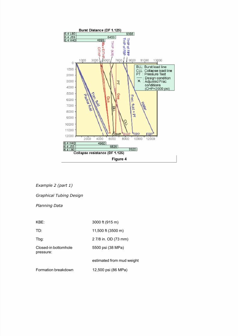
7242019 Completion Equipment
httpslidepdfcomreaderfullcompletion-equipment 784
pressure
estiated fro offset ampell
8racture propagationpressure
2 psi 9( Pa3
estiated fro offset ampell
Packer fluid inhibited oil ( psi7ft3
Production expect sour gas
gas graity reseroir3
gas graity 6 separator3
)55 or lt tubular to be used
tiulation fracture expected assue 2 barrels per inute3= axiualloampable annulus pressure is 2 psi 1(6 kPa3
T Estimate
Depth ofHole
Gas Gravity
ft $ $amp $ $(
1 (5 6 6 69 6(
2 91 5 59 5( gt9
( 15 ( (5 ( 2
gt 121 2 1gt 6 5
5 152gt 1 ( 5 6
9 1( ( 6( 5gt gt6
6 21(( 9gt 5gt gtgt 2(
2gt( gt6 (5 2( 1
26gt( 2 19 gt 66
1 (gt 12 6 69gt 65
11 ((5( 65 6 699 6(6
12 (99 66 69( 6gt6 616
7242019 Completion Equipment
httpslidepdfcomreaderfullcompletion-equipment 884
1( (92 69( 6gt9 62 96
1gt gt296 6gt6 62 612 96
15 gt562 6(2 61( 95 95
19 gt69 616 96 96 9gt1
16 511 62 92 952 92gt
1 5gt9 96 959 9gt5 96
1 561 96( 952 9(1 5
2 96 95 9(6 915 56gt
Table 2 7atio bet-een surface ressure and bottomhole ressure in gas -ells for a
range of gas graities
t a gas graity I$P 626 IBP ( psi
At a gas grait E 0 ITHP E 0 I2HP E 44 si
8or a kill situation bottohole inAection pressure IBP 2 psi 55 psi 2 psi 65psi
If gas graity $IP 626 BIP 6263 653
E43 si
Assumed Fracture Conditions 1 8oration breakdoampn achieed ampith ampater
ltracture 8ob carried out -ith -aterbase fluid
8riction loss in 2 67 in tubing at 2 BP using ampater ampith friction reducer is (5 psi71 ft for115 ft 4oampell andbook3
8PP 2 psi
ltriction E F40 si (30 )
Head E si (04 00)
ltrac THPE 00 si
Prepare a depth pressure plot 8igure 2 3 in the folloamping anner 1 Plot the closed-in bottohole pressure IBP3
Plot the formation brea6do-n ressure (lt2P) and the fractureroagation ressure (ltPP)
7242019 Completion Equipment
httpslidepdfcomreaderfullcompletion-equipment 984
3 Plot the ac6er fluid gradient fracture fluid gradient and -atergradient
4 gtstimate -et and dr gas gradients and lot these u from the
closedin bottomhole ressure
gtstablish the closedin tubing head ressure for normal roductionconditions (ie oil or as in this case -et gas) and for -orst case
design assumtion (usuall dr gas)
gtstablish ma1imum THP for -hich comletion is to be designed
-hich normall -ill be 6ill or stimulation conditions (fluid gradientthrough lt2P ltPP or secified differential aboe ITHP) ltor gt1amle
the grahical design should no- loo6 li6e ltigure
gtstablish through insection the greatest differential ressure at
surface and do-nhole (usuall stimulation conditions) Getermine -hatstes can be ta6en to reduce loading (eg maintaining ma1imum
allo-able annulus ressure during stimulation) Plot ad8usted annulusressure line ( ltigure 3 )
Plot burst load line (2$$) as difference bet-een most critical tubingand annulus ressures The 2$$ is a function of the relatie densities in
the tubing and annulus 2$$ -ill generall but not al-as decrease-ith deth ( ltigure 3 )
Plot critical collase load conditions ($$) ampormall -e assume thata slo- lea6 has changed the HP to ITHP and that tubing is emt
and deressured This can occur in gas -ells if the tubing becomeslugged or a do-nhole safet ale is closed onditions can aroach
this situation in oil -ells after a fracture treatment if oeratorscommence 6ic6off before bleeding off annulus ressure (In some
cases this ma be a more critical load ( ltigure 4 ))
0 Plot ressure test conditions (PT) This is often the most critical
load to -hich a comletion is sub8ected onsider timing of the
ressure test and densit of fluids in the tubing and annulus at time oftest
$oo6 u tubing erformance data in API 2ulletin
Ad8ust API internal ield (burst) and collase resistancesecifications -ith design factor (see ltigure and API 2ulletin )
3 $ist resulting tubing caabilities ( ltigure 4 )
4 omare design loads -ith tubing caabilities and select tubing In
most cases the otimum tubing grade and -eight -ill ar -ith deth
To minimi+e costs andor tensional loads such ariations ma beincororated although there -ill then be a constraint on ressure
testing caabilities Ho-eer most oerators refer to use a common
7242019 Completion Equipment
httpslidepdfcomreaderfullcompletion-equipment 1084
-eight and grade throughout the comletion if ossible This reducesthe ris6 of installation and oerating errors =hen regulations ermit
the designer ma be able to comromise slightl on accommodatingloading conditions dee in the hole if the associated design
assumtion is e1tremel unrealistic (eg a comletel emt tubing ina high roductiit oil -ell) Ho-eer the designer must first chec6 on
ho- critical the actual bia1ial (or tria1ial) loading conditions are li6elto be and ma6e aroriate notes in the -ell file
Cith reference to Exaple 2 in 8igure gt the options include the folloamping 1 full string of 9gt lb7ft lt tubing
0 to 00 ft E 4 lbft J00 to TG E 4 lbft $0
3 full string of 4 lbft J -ith modified collase design criteria of000 si as ma1imum HP -ith an emt tubing
ince 2 psi is the axiu alloampable annulus pressure during stiulation option ( ay bean acceptable design ince the differential cost of )55 and lt is around D( per ft the potentialsaing of D(gt5 betampeen options 1 and ( ay Austify further detailed engineering ampork n theother hand if the ampellstrea is expected to be extreely corrosie the higher grade tubing aybe selected in any case to proide a corrosion alloampance
The 6e things to note from ltigure (Effect of buoyancy on axial load ) are
bull the ost seere burst loadings occur at surface
7242019 Completion Equipment
httpslidepdfcomreaderfullcompletion-equipment 1184
Figure amp
bull the most seere burst and collase loadings occur during ressure testing
-ell 6ill and stimulation
bull the most seere collase loading occurs do-nhole
bull additional annulus ressure can be used to reduce burst loading roided
the casing is strong enough
bull the tubinghead ressure during 6ill oerations (THIP) often aro1imates or
e1ceeds the reseroir ressure (I2HP)
Cith relatiely sall tubing strings (5 in or 3 the inherent burst and collapse strength isso high that soe engineers do not bother ampith tubing design in ampells ampith depths of less than ft 25 3 unless oerpressures are expected
Simplified Tensional Strength Design
Although burst and collase resistance ma not be significant considerations inuming -ells tensional strength is a critical design arameter for all -ells ouling
lea6age and failure -hich accounts for 0 of the roblems in -ell tubulars often
7242019 Completion Equipment
httpslidepdfcomreaderfullcompletion-equipment 1284
ma be the result of inadeuate tensional design rather than a burst or sealingroblem In this resect it is articularl imortant to remember that test ressures
imose substantial iston forces on the tubing (eg a 000 si (3 Pa) ressuretest on a lug set inside in (3mm) tubing -ill increase the tension on the
hanger b (000)( 4)(44l) E 30 lb (4 6amp)
It is also imortant to recogni+e that unli6e other strength arameters the API 8ointstrength is based on a failure condition rather than the onset of lastic deformation
The failure condition is either an un+iing of the in and bo1 in the case of APIthreads because of ielding (also called 8umout)D or brea6age of reduced cross
section at the threads in the case of suare threads
ltinall there are all sorts of additional tensional loads that -e do not normallanal+e in detail (eg shoc6 loading and drag forces during running bending
stresses buc6ling crosssectional iston forces changes in buoanc)
ince it is common ractice to ma6e a reliminar tensional design using tubing
-eight loading onl a higher design factor is used for tension and eseciall for 8oint
strength (Table 1 aboe) ome comanies and more conseratie engineers -illeen ignore the otential benefits of buoanc 2uoanc results in a iston force onthe lo-er end of the tubing and as a first aro1imation it ma normall be assumed
that
12amphere
CB buoyant ampeight
=amp E -eight in air
E densit of steel ( gmcc)
E densit of fluid
8igure 5 graphically depicts the tensional and copressional forces at ampork on a tapered string of tubular goods $he load resulting fro the ampeight of the pipe is shoampn for a string ampeighed in airand ampith the buoyant forces accounted for as piston forces or approxiated using EFuation 12Ce can see that at a point approxiately idampay in the length of the heaier pipe at the bottoof the string there is a change fro copression to tension $his is also the concept amphich guidesthe design of drillstrings ampith the purpose of keeping the drillpipe in tension amphile using theheaier drill collars to aintain a copressional load on the bit
Part of gt1amle gies the reliminar tension design considerations for thecomletion alread coered in art
Example 2 (part 2
reliminary Tension Design
7242019 Completion Equipment
httpslidepdfcomreaderfullcompletion-equipment 1384
$ubing ampeight 9gt lb7ft
Tubing length 00 ft
Pac6er fluid inhibited oil
03 sift E 0 gmcc
=amp E 4 00E 300 lb
E 0 300
E 04 lb
Joint Specifications
)55 lt
EGE H4 EGE H4 5
PI Aoint strengthKlb3
6 1 1(5 12
4esign factorTable 13
1 1 1 1
4esign capacityKlb3
55gt 559 655 611
Tubing Tension Design Considerations 1 eFuires lt tubing at surface
7euires 8oint strength caabilit of gtKgt or euialent
3 In ie- of ressures deth and H -ould robabl select remium
grade couling
any copanies hae these design techniFues prograed for the coputer and use the saegeneral techniFue for both tubing and casing designs
Tubing Design Parameters
It is imortant to remember that -hile the rimar function of the tubing is as aconduit for hdrocarbon roduction or for in8ection of -ater or gas the most seere
loadings often occur during -ell serice or 6illing oerations or during ressuretests It is therefore rudent to ma6e roision for these oerations -hen designing
a comletion and to chec6 out the tubing limitations -hen lanning a -ell sericingoeration (eg a stimulation or a -or6oer) are must be ta6en not to increase
comletion costs e1cessiel b tring to ma6e roisions for all sorts of unli6el butossible occurrences It must also be remembered that there are stes that can be
7242019 Completion Equipment
httpslidepdfcomreaderfullcompletion-equipment 1484
ta6en to mitigate the induced stresses during man oerations (eg alingannular ressure or heating fracturing fluids) Ln the other hand the conseuential
costs of a failed tubing string or of haing to run a secial -or6ing string in termsof deferred roduction and rig time can be uite substantial Assessment of the
most cost effectie solution is generall a 8udgment call based on the engineer5se1erience and on cororate attitudes and olic A tical set of arameters has
alread been illustrated in gt1amle
urst
The tubing and -ellhead should be designed for suee+e and 6ill conditions incefines in the erforations or oil can sometimes cause a chec6 ale effect -hen
attemting to suee+e bac6 liuids man comletion designers li6e to hae thefle1ibilit of being able to raise the bottomhole ressure to the lt2P or at least to the
ltPP Ho-eer -ith high ermeabilit reseroirs or gas -ells in -hich fracturestimulation is unli6el comletion engineers are often satisfied -ith a certain
minimum differential for in8ection The alue selected aries from area to area andfrom coman to coman but is commonl either around 000 si ( Pa) or 33
of the reseroir ressure The author suggests
1 8BP amphere k1 1 d kg 5 d
ltPP for suee+ing liuids -here 6 00 md
3 I2HP F 000 si ( Pa) for suee+ing gas -here6g 0 mdD or for suee+ing liuids -here 6 000 md
8ro the rock echanics theory presented by eertsa 163 and others it ay be deducedthat in a tectonically relaxed area a proisional estiate of the fracture propagation gradient8P3 can be obtained fro the eFuation
13
ltPM N lt2M N sift ( 6Pam) 1
amphere s oerburden stress J1 psi7ft depth3
E ore ressure si
G E deth ft
ltPM E formation roagation gradient sift
lt2M E formation brea6do-n gradient sift
$he specification of the pressure test conditions is often critical to burst design oernentregulations soeties specify pressure test conditions eg to at least 0 of the reseroirpressure or to 1 psi 5 Pa3 oer the axiu differential pressure expected at the packer3If no regulations exist ost operators test to their tubing design conditions
7242019 Completion Equipment
httpslidepdfcomreaderfullcompletion-equipment 1584
$ollapse
eere collase loads on the tubing can occur
bull in gas ampells and high oil ampells ampith loamp-floamping botto-hole pressures and deep-set safety ales after bloampdoampn to test a plug etc
bull during annulus ressure tests or oeration of shear circulation deices
bull -here there are ressured annuli
bull during underbalance erforating or testing at high dra-do-n
bull during tubing blo-outs
It is iportant to reeber that tension reduces collapse strength $his biaxial effect should beexained for large diaeter tubings especially if reduced collapse design assuptions and7or adeep-set safety ale is used
Tension
Tubing strings are not onl sub8ected to running tensions -ith all the associatedshoc6 and acceleration loadings but also to aring oerating stresses due to iston
forces on the steel andor an lugs ums standing ales and the li6e in thetubing oreoer if the tubing is anchored or held b a ac6er its oerating tension
-ill ar as a result of
bull theral effects hot production or cold kill fluid3
bull iston effects (changes in buoanc and forces at 8oint usets)
bull ballooning effects (changes in internal or e1ternal ressure)
bull buc6ling effects (longitudinal instabilit)
$hese potential probles are listed in ters of their ost coon relatie agnitude althoughthe relatie iportance of piston and ballooning effects is ariable3
$ombined oading
=hile the designer of tubular goods normall tal6s in terms of burst collase and
tension comression as if the -ere indeendent it is obious that in most actualloading situations the occur simultaneousl Precise stress analsis should reallconsider a tria1ial loading situation
The simultaneous solution of all the associated euations is rather comlicated Anumber of comuter rograms are aailable but for most field engineers the -ill be
a blac6 bo1 solution This can be dangerous It is imortant to chec6 that theformulas are roerl handled articularl -ith resect to collase -hich is a
stabilit effect Therefore it is usual for critical stress analses (eg for ultra dee
7242019 Completion Equipment
httpslidepdfcomreaderfullcompletion-equipment 1684
high ressure or sour -ells) to be underta6en b a secialist consultant researchgrou or intracoman tas6 force oreoer since this is not the routine design
techniue design factors are less -ell roen (although a alue of is oftenused)
A more conenient aroach for the intermediate range moderatel comle1 design
roblem is to use the ellise of bia1ial ield stress roosed b Holmuist and ampadai(3) The critical relationshis are (a) tension reduces collase resistanceD (b)comression reduces burst resistance
The other imortant concet in the consideration of tria1ial loads is that ressurechanges affect a1ial stresses or cause tubing moement This has been e1tensiel
discussed in Pgt aers b $ubins6i () Hammerlindl () and tillebroer()
ending
2ending stresses can be significant in large tubulars The are comressie in the
inner -all and tensional in the outer -all the most detrimental being
1ampamphere
the radius of curature ft3
sb E bending stress
gt E Ooung5s modulus (for steel gt E 30 0 si)
do E outside diameter of the tubular
Bending stresses result fro both hole curature and buckling $he effects of doglegs need onlybe considered if they are ery seere 1L71 ft= 1L7( 3 or if ery large tubing 5 172 to 6 in=1gt to 16 3 is being used
Production Casing
The roduction casing must be adeuatel si+ed for the lanned comletion It -illobiousl affect the si+e of the other reuired casing strings the bit selection the
caacit of the rig and the oerall -ell costs The roduction casing must bedesigned for the loads that ma be imosed during the roducing life of the field It
is similar to tubing design in seeral -as
urst
Production casing must be designed to -ithstand the ma1imum closedin tubing
ressure that can be e1ected If a ac6er has been used this ressure is assumed
to be alied at the to of a full column of ac6er fluid (ie for the case of a tubing
7242019 Completion Equipment
httpslidepdfcomreaderfullcompletion-equipment 1784
failure at the surface) =e usuall assume that the e1ternal ressure resisting burstis a -ater gradient If the ac6er fluid is heaier than -ater the burst load -ill
increase -ith deth
In the eent that a snubbing oeration could not be conenientl attemted if atubing brea6 occurs at the surface the casing must be strong enough to -ithstand a
bullhead suee+e on the lie tubing string in -hich case this -ould be the designcriteria for the casing and -ellhead
In man cases it ma be necessar to design the casing for loads imosed during
stimulation and ressure testing onersel the casing caacit must be chec6ed-hen designing a fracturing treatment This is articularl imortant in -ells -here
no ac6er is used
$ollapse
Production casing ma be sub8ect to comlete eacuation during roductionoerations if the -ell is oerated on gas lift or umedoff or if the ac6er or
-or6oer fluid is lost into a deleted +one As the ie ma hae deteriorated beforethis occurs a higher design factor (F) is often used for roduction casing
eere collase loads ma occur in situations in -hich thermal e1ansion of theannular fluid bet-een the roduction and intermediate strings cannot be bled off
(eg in some subsea -ells)
Increased loading should be assumed if lie annuli are a feature of the area 7educed
loadings ma be assumed if the -ells -ill not be umed off gas lifted or seereldeleted
eere collase loads ma e1ist in the a section during high dra-do-n
underbalanced erforating and testing and suee+e either or both cementation andfracturing ( ltigure $ollapse loads in the pay ) It is highl adisable to maintainsome set casingtubing annulus ressure during such serice oerations
7242019 Completion Equipment
httpslidepdfcomreaderfullcompletion-equipment 1884
Figure 1
Tensionamp$ompression
In high rate roduction areas and thermal -ells e1ansion of the roduction tubingma imose additional tension on the casing strings ia the ac6er
$ouplings
In high ressure (000 siD 34 Pa) high temerature (300B ltD 4 ) andor
seerel sour conditions remium casing coulings are recommended
aterial Selection
In sour enironments material secification must consider the chances of Hcontamination of the casingtubing annulus and the added ossibilit of temerature
changes during stimulation affecting the stress corrosion tolerance of the ie
Couplings
There are man forms of couling aailable some of -hich hae been dedicated tothe ublic through the ausices of the API -hile others are roduced b or under
7242019 Completion Equipment
httpslidepdfcomreaderfullcompletion-equipment 1984
license from a secific manufacturer It -as in fact the need to obtain astandardi+ation of thread forms and diameters that led to the formation of the API
ommittee on tandardi+ation of Tubular Moods in 4
The API coulings ( ltigure
Figure 1
ltigure and ltigure 3
7242019 Completion Equipment
httpslidepdfcomreaderfullcompletion-equipment 2084
Figure 2
$utaways of basic types of couplings) are of three basic tes e1ternal uset (gtKgt)
nonuset (ampK) and integral 8oint
7242019 Completion Equipment
httpslidepdfcomreaderfullcompletion-equipment 2184
Figure 3
Threads are of t-o main forms The round API threads are -ea6er than the ie
bod (ie N00 efficient) The buttress threads -ere deeloed b the ampationalTube Giision of the Knited tates teel ororation to roide a high strength
couling for dee high ressure -ell serice This thread is used in a number ofrorietar coulings eg Hdril A Atlas2radford
All taered threads achiee a seal b driing the in and bo1 surfaces together undersufficient stress to generate a bearing ressure e1ceeding an differential that is to
be subseuentl alied Ho-eer a small siral oid is al-as left bet-een themating surfaces and must be filled -ith solids in the form of thread comound (This
is the reason for careful secification of the comound in 2ul A) Ln API roundthreads this oid occurs bet-een the crest and root of the mating threads -hile on
buttress threads it e1tends oer the -hole flan6 of the thread on the beeled side
To imroe lea6 resistance eseciall at eleated temeratures and under high
ressure differential the socalled remium seals -ere deeloed These consist of either metaltometal seals on taered ortions of the in and bo1 surfaces or an
elastomer seal ring or both This te of seal reuires a high ualit finish andrecise gauging and insection The couling is therefore more costl ince API and
7242019 Completion Equipment
httpslidepdfcomreaderfullcompletion-equipment 2284
buttress threads hae roen to be er reliable in the field the decision to use themore e1ensie remium seals reuires careful economic 8ustification In general
their alication has roen aluable in highl corrosie conditions in high ressuregas -ells or high ressurehigh ML7 oil -ells and in thermal -ells sub8ect to high
comressie loads The ma be used -here -or6oer costs are high (egoffshore) In general API tubulars are adeuate for differential ressures of less than
000 si (344 Pa) and temeratures of less than 300B lt (0B ) using hightemerature thread comound ltor corrosie conditions and continuous gas sericethe ressure limit is often reduced to 00 si ( Pa)
gt1ercises
)ilfield nits
The in 4 lbft J ampK tubing string in a 000ft oil -ell -as designed
based on the tubing5s buoant -eight in -ater =hat additional load -ould beimosed on the tubing if a rod um -ere to be ressure tested to 00 si after the
-ell had been oerating for some time and the annulus umed offQ The -ell
roduces 30B API oil (M 0) -ith no -ater
If coman olic dictates the use of a design factor of for 8oint strength can
this ressure test be safel carried outQ
SI nits
The 3mm ( in) 6gmm (4 lbft) J ampK tubing string in an 30moil -ell -as designed based on the tubing5s buoant -eight in -ater =hat additional
load is imosed on the tubing if a rod um -ere to be ressure tested to 3 Paafter the -ell had been oerating for some time and the annulus umed offQ The
-ell roduces 6gm3 oil (M 0) -ith no -ater
If coman olic dictates the use of a design factor of for 8oint strength can
this ressure test be safel carried outQ
olutions
)ilfield nits
=eight in air E 000 ft 1 4 E 3400 lb
2uoanc in -ater E E 0
(densit of -ater gmccD densit of steel E gmccD use gtuation )
12
7242019 Completion Equipment
httpslidepdfcomreaderfullcompletion-equipment 2384
Buoyant ampeight amphen run (gt x 65 ((9 lb
=ater gradient (M E ) E 0433 sift
Lil gradient (M E 0) E 0 1 0433 E 03 sift
IG of tubing E 44 in Ai E 40 in
=eight of oil in tubing E 000 1 03 1 40 E 04 lb
Total alied tensile force at the surface after -ell has been umed off euals
Ceight of oil ampeight of tubing in dry casing applied pressure x area of tubing I4 19gt2 (gt 5 gt93 19gt2 (gt 2(gt 51(2 lb
The API 8oint strength rating of in 4 lbft J nonuset tubing E 00lb
If a design factor of for 8oint strength is dictated b coman olic the
allo-able tensile loading (-ith design factor) E (00) ()E 4400 lb
Therefore the roosed loading e1ceeds the design secifications and a lea6 mightoccur during the test In fact the loading e1ceeds design secs een -ithout adding
the 00 si of -ellhead ressure (actual load 404 lb comared -ith an allo-ableof 4400 lb) Ho-eer using a 33 design factor for oerating loading conditions
ressure tests of u to 4 si -ould be ermissible
6293 1((3 19gt2 (gt pt gt93
Pt E 4 si
+ nits Ceight in air 1( x 5 16(5 kg 165 kM
2uoanc factor in -ater E E 0
(densit of -ater E gmccD densit of steel E gmccD use gtuation )
12Buoyant ampeight amphen run 165 x 65 1gt2 kM
=ater gradient (M E 0) E 4 6PamLil gradient (M E 0) 0 1 4 E 6Pam
7242019 Completion Equipment
httpslidepdfcomreaderfullcompletion-equipment 2484
IG of tubing E mm thus Ai E 30 1 l04 m
=eight of oil in tubing E (30 m) ( 6Pam) (30 1 03 m)E 44 6amp
Total alied tensile force at the surface after -ell had been umed off euals
Ceight of oil ampeight of tubing in dry casing applied pressure x area of tubing I4 gt6gt 165 (5 (1 x 1 -(3 gt6gt 165 156 22gt6 kM
8ro 8igure 1 the PI Aoint strength rating of 6(- 5 kg7 )-55 nonupset tubing is
629 lbs (222 kM3
Figure 1
If a design factor of for 8oint strength is dictated b coman olic the
allo-able tensile loading (-ith design factor)
(222715 2152 kM
7242019 Completion Equipment
httpslidepdfcomreaderfullcompletion-equipment 2584
$herefore the proposed loading exceeds the design specifications and a leak ight occur duringthe test In fact the loading exceeds design specifications een at ero ampellhead pressure actualload of gt6gt 165 216 kM copared ampith an alloampable load of 2152 kM3
Ho-eer using the 33 design factor for oerating loading conditions ressure tests
of u to 6Pa -ould be ermissible
216 pt (1 x l-gt3
t E 4 6Pa
2 )ilfield nits 12-ft hydrostatically pressured gas ampell γ g 63 is to be copleted Chat closed-in tubing
head pressure can be expectedN If the casing ampellhead and tubing are to be designed for asFueee kill at fracture propagation pressure 8PP3 amphat ampellhead pressure ampould be expected atthe start of the kill operationN Gse EFuation 1( for estiating the 8P3
13
+ units (99- hydrostatically pressured gas ampell γ g 63 is to be copleted Chat closed-in tubinghead pressure is expectedN
If the casing -ellhead and tubing are to be designed for a suee+e 6ill at fractureroagation ressure (ltPP) -hat -ellhead ressure -ould be e1ected at the start
of the 6ill oerationQ (Kse gtuation 3 for estimating the ltPM)
olutions
)ilfield nits
Condition Loading Design Criteria Typical Design Factor
Burst Internal Kill pressure on
hydrocarbon-filled tubing
1125
External Packer fluid and eroannulus pressure
onsiderations heck effects ofcopression
ollapse External asing head pressure 1125
7242019 Completion Equipment
httpslidepdfcomreaderfullcompletion-equipment 2684
shut-in tubing pressure
Internal $ubing epty anddepressured
onsiderations heck effects of tension
$ension unning Buoyant ampeight in Body 1(((
copletion fluid )oint 1+
$ension andopression
perating old stiulation and hotproduction conditions
Body 1125
)oint 1(((
onsiderations heck effects ofteperature andpressure changes
$otal tress $riaxial ax stress 0 yield
CAssuming searate chec6s are not lanned on shoc6 and bending effectsD other-iseuse
Table 1 Typical criteria for tubing design on a flowing well
The ratio of THP to 2HP for γ g of 0 E 04
At 000 ft assuming a hdrostatic gradient of 0433 sift the bottomholeressure can be estimated as
BP 12 x gt(( 519 psiampith gas surface pressure 519 x 6gt6 I$P (1 psi
Assuming the oerburden gradient to be sift and using gtuation 3 to estimate
the fracture roagation ressure
E 0 sift
ltPP E 0 000 ft E 04 si
axiu ampellhead pressure at the start of the kill operation $IP3 ampill eFual the forationpropagation pressure inus the pressure due to the gas gradient
7242019 Completion Equipment
httpslidepdfcomreaderfullcompletion-equipment 2784
$IP 12 6163 - 519 - (13 62 psigore correctly ampe should use the ratio in Table 1 since the increased pressure ampill increase thegas density
$IP 12 6163 6gt6 9gt26 psi$herefore a 5 psi ampellhead should not be used een though the axiu closed-in tubinghead pressure is only about gt psi
SI nits
7eferring to Table 1
The ratio of THP to 2HP for γ g E 0 E 04
At 30 m assuming a normal hdrostatic ressure of 6Pa m bottomholeressure can be estimated as
BP (99 65 (55 kPa
ampith gas surface pressure (55 6gt6 I$P 296 kPa
Assuming the oerburden gradient to be 6Pam and using gtuation 3 toestimate the fracture roagation ressure
E 6Pam
ltPP E 30 E 3 6Pa
axiu ampellhead pressure at the start of the kill operation $IP3 ampill eFual the foration propagation pressure inus the pressure due tothe gas gradient
THIP E (30 ) (30 0) E 0 6Pa
ore correctly ampe should use the ratio in Table 1 since the increased pressure ampill increase thegas density
$IP (99 19213 6gt6 gtgt(1 kPa
9gt Pa ampellhead should therefore be used
3hellip)ilfield nits
A 000ft -ell that is to be roduced -ith a target of 000 T2d using intubing encounters 0 ft of oilbearing formation -ith a ressure of 3000 si =hat
rating of -ellhead should be usedQ If a single grade and -eight of tubing is to be
7242019 Completion Equipment
httpslidepdfcomreaderfullcompletion-equipment 2884
used -hat is the cheaest string that can robabl be run assuming that
Grade -eight lbft
Collapse
+trength psi
urst
+trength psi
Tensional
+trength 1 lb
Cost Coparison
)-55 155 gtgt gt1 ( cheapest
16 gt1 5(2 (2
-65 16 96 625 gt2( ost expensie
M- 16 92 66gt gtgt9 oderately expensie
2 ( 52gt
ac6er fluid inhibited sea-ater (gradient E 043 sift)
reseroir ressure 3000 si
6ill ressure 000 si aboe I2HP (suee+ing gas)N fracture roagation ressure (suee+ing oil)
ltracture roagation ressure gradient (ltPM) is aro1imatel
8P 5 5 psi7ft3
If gas cap gas should break through into the ampell assue gas graity 95
Kse Table 1 to calculate head of gas
Condition Loading Design Criteria Typical Design Factor
Burst Internal Kill pressure onhydrocarbon- filledtubing
1125
External Packer fluid and ero
annulus pressure
onsiderations heck effects ofcopression
ollapse External asing head pressureshut-in tubing pressure
1125
Internal $ubing epty and
7242019 Completion Equipment
httpslidepdfcomreaderfullcompletion-equipment 2984
depressured
onsiderations heck effects of tension
$ension unning Buoyant ampeight incopletion fluid
Body 1((( )oint 1+
$ension andopression
perating old stiulation and hotproduction conditions
Body 1125)oint 1(((
onsiderations heck effects ofteperature andpressure changes
$otal tress $riaxial ax stress 0 yield
CAssuming searate chec6s are not lanned on shoc6 and bending effectsD other-iseuse
Table 1 Typical criteria for tubing design on a flowing well
Assume lie oil gradient is 03 sift
onsider onl the ma1imum burst at the -ellhead the ma1imum collase load at theac6er and the running tension
SI nits
A 30m -ell that is to be roduced -ith a target of 400 m3da of oil -ith l40mm ( inch) tubing encounters 0 m of oilbearing formation -ith a ressure of
000 6Pa =hat rating of -ellhead should be usedQ If a single grade and -eight oftubing is to be used -hat is the cheaest string that can robabl be run assuming
that
Grade -eight
$gmm
Collapse
+trength
$Pa
urst
+trength
$Pa
Tensional
+trength
$amp
Cost Coparison
)-55 2(1 2655 ((19gt 1((gt cheapest
25( ((5( (99 1gt9(
-65 25( gt151 gt6 12 ost expensie
M- 25( gt(2 5((95 1gt oderately expensie
2 9 91gt 2((1
7242019 Completion Equipment
httpslidepdfcomreaderfullcompletion-equipment 3084
ac6er fluid inhibited sea-ater (gradient E 40 6Pam)
reseroir ressure 000 6Pa
6ill ressure 000 6Pa aboe I2HP (suee+ing gas)N fracture roagation ressure (suee+ing oil)
ltracture roagation ressure gradient (ltPM) is aro1imatel
8P 53 22(3 5 kPa7If gas cap gas should break through into the ampell assue gas graity 95
Kse Table 1 to calculate head of gas
Assume lie oil gradient is 6Pam
onsider onl the ma1imum burst at the -ellhead the ma1imum collase load at the
ac6er and the running tensions
olution
)ilfield nits
I$P IBP - o 4
o ( psi7ft
under operating conditions I$P ( - ( 63 psi
under axiu conditions assuing gas breakthrough3
ITHP E 04 1 2HP (from Table 1)
AR ITHP E 04 1 3000 E si
under 6ill conditions
8P 5 5
5 5 x 61 psi7ft
ltPP E 000 0
E 000 si
7242019 Completion Equipment
httpslidepdfcomreaderfullcompletion-equipment 3184
O BIP oil kill3
5 psieFuialent $P oil kill3
5 - ( x 6 2 psi
In the case of a gas kill
Iamp 2HIP(gas 6ill)
( 1 psi gt psi
eFuialent $P gas kill3
5gt x BP 5gt x gt (gt19 psi
8ro this ampe see that amphile ampe could probably get aampay ampith a ( psi ampellhead strictlyspeaking ampe should be using a 5 psi ampellhead
Incororation of the roision in some regulations for a -ellhead rating euialent
to the reseroir ressure reflects this tical design for 6ill caabilit
Tubing urst (ating
burst rating E ma1 THP design factor
design factor E
reuired burst rating (for gas 6ill conditions) E 34 E 343 si
All grades and -eights satisfactor
Tubing Collapse )oading Calculation
alculate first assuming a high ris6 of gas brea6through
head of packer fluid f 3 43 gt(53 63 (gt5 psi
ma1 HP E ma1 ITHP (assumes lea6)E si
ma1 2H annulus ressure E F 304E 0 si
7242019 Completion Equipment
httpslidepdfcomreaderfullcompletion-equipment 3284
ma1 collase load E 0 0 si (assumes emt tubing)E 0 si
design factor E
reuired collase rating E 0 1 si
E 30 si
$herefore strictly speaking ampe should use 2-lb7ft M- tubing although it is ore likely a l6-lb7ft ampould be selected since the probability is ery loamp that such seere collapse-loadingassuptions ampould proe true
alculate ne1t assuming a lo- ris6 of gas brea6through
ax P operating I$P
oerating ITHP E 00 si
ma1 2H annulus ressure E 00 F 304 siE 34 si
ma1 collase load E 34 si
reuired collase rating E 34 E 443 si
Ce could select 16 lb7ft )-55 tubing
(unning Tension Calculations
ampeight in air C 4 16 lb7ft3 6 ft3 11 lb
buoyancy factor
625
buoant -eight of tubing E 0 000 lb
E 04000 lb
design factor E
reuired tension rating E (04000) () lb
16 lb$his can be easily carried by any of the tubing grades listed
7242019 Completion Equipment
httpslidepdfcomreaderfullcompletion-equipment 3384
It is tical for collase design to be the critical factor in highrate largetubingcomletions eseciall at relatiel shallo- deths
Conclusion
in 0lbft amp0 tubing meets all criteria for this te of roduction 7is6 of
gas brea6through must be accuratel assessed before choosing bet-een amp0 and J grades
SI nits
I$P IBP - ρo x 4
ρo 969 kPa7
under operating conditions I$P 26 - 969 x 21(3
92gt9 kPaunder axiu conditions gas breakthrough3
ITHP E 04 1 2HP (from Table 1)
AR ITHP E 04 1 000 E 6Pa
under 6ill conditions
8P 53 22(3 5
53 22(3 5
19 kPa7
ltPP E (30) (00)
E 3400 6Pa
O BIP oil kill3 (gt kPa eFuialent $P oil kill3 (gt - 969 x 21(3
1929 kPa
In the case of a gas 6ill
Iamp 2HIP
(gas 6ill) E 000 F 000 6Pa
266 kPaeFuialent $P gas kill3 5gt x BP
5gt x 266 2(959 kPa
8ro this ampe see that amphile ampe could probably get aampay ampith a 26 Pa ampellhead strictlyspeaking ampe should be using a (gt5 Pa ampellhead
7242019 Completion Equipment
httpslidepdfcomreaderfullcompletion-equipment 3484
Incororation of the roision in some regulations for a -ellhead rating euialentto the reseroir ressure reflects this tical design for 6ill caabilit
Tubing urst (ating Calculation
burst rating E ma1 THP 1 design factor
design factor E
reuired burst rating (for gas 6ill conditions) E 3 1
E 3 6Pa
All grades and -eights satisfactor
Tubing Collapse )oading
alculate first assuming high ris6 of gas brea6through
head of packer fluid ρf 3 43
gt3 21(3 25 kPa
ax P ax I$P assues leak3 1696 kPa
ma1 2H annulus ressure E F 0
E 33 6Pa
ma1 collase load E 33 0 6Pa (assumes emt tubing)
E 33 6Pa
design factor E
reuired collase rating E 33 1 E 434 6Pa
Therefore strictl sea6ing -e should use a 6gm amp0 tubing but moreli6el 36gm tubing -ould be selected since the robabilit of such seere
collase loading is er lo-
alculate ne1t assuming lo- ris6 of gas brea6through
ax P operating I$P
oerating ITHP E 4 6Pa
ma1 2H annulus ressure E 4 F 0
E 0 6Pa
ma1 collase load E 0 6Pa
7242019 Completion Equipment
httpslidepdfcomreaderfullcompletion-equipment 3584
reuired collase rating E 0 1 E 300 6Pa
Ce could select 25(-kg7 )-55 tubing
(unning Tension Calculation
ampeight in air 25( 21( 5( kg 525 kM
buoanc factor E
EE0
buoant -eight of tubing E 0 6ampE 4 6amp
design factor E
reuired tension rating E (4) ()
E 30 6amp
$his can be easily carried by any of the tubing grades listed
It is tical for collase design to be the critical factor in highrate largetubing
comletions eseciall at relatiel shallo- deths
Conclusion
40mm ( inch) 36gm 0 tubing meets all criteria for this te ofroduction 7is6 of gas brea6through must be accuratel assessed before choosing
bet-een 0 and J grades
Pac6ers
Pac$er unctions
A ac6er is a subsurface tool that roides a seal bet-een the tubing and
casingthereb reenting the ertical moement of fluids across this sealing oint
Pac6ers are used for the follo-ing reasons
9 to imroe safet b roiding a barrier to flo- through the annulus
7242019 Completion Equipment
httpslidepdfcomreaderfullcompletion-equipment 3684
9 to 6ee -ell fluids and ressures isolated from the casing
9 to imroe flo- conditions and reent heading
9 to searate +ones in the same -ellbore
9 to lace 6ill fluids or treating fluids in the casing annulus
9 to ac6 off erforations rather than use suee+e cementing
9 to 6ee gas lift or hdraulic o-er fluid in8ection ressure isolated from the
formation
9 to anchor the tubing
9 to install a casing um
9 to minimi+e heat losses b allo-ing the use of an emt annulus or thermal
insulator
9 to isolate a casing lea6 or lea6ing liner la
9 to facilitate temorar -ell serice oerations (eg stimulations suee+es)
Pac$er T+pes
There are man ac6er manufacturers some of -hom offer an e1tensie ariet ofac6ers -ith each differing to some degree from those of the other manufacturers
This rather be-ildering arra can ho-eer be groued into rincial classes or
tes and ma be further categori+ed b method of setting b direction of ressureacross the ac6er and b the number of bores through the ac6er
Pac6ers can be rimaril classified as either retrieable or ermanent or
ermanentretrieable or inflatable
)etrievable acers
This te of ac6er is run on the tubing ( ltigure )etrievable pacer )
7242019 Completion Equipment
httpslidepdfcomreaderfullcompletion-equipment 3784
Figure 1
After setting it can be released and recoered from the -ell on the tubing ince it is
an integral art of the tubing string the tubing cannot be remoed from the -ell-ithout ulling the ac6er unless a detachable ac6er head is used
7etrieable ac6ers ma be designed to be set mechanicall or hdraulicallechanical setting methods include rotation of the tubing string recirocation of the
tubing string or the alication of tension or setdo-n -eight =ith mechanical
ac6ers the tubing is usuall set in comression
Hdraulic ac6ers are set b aling hdraulic ressure through the tubing stringbut once set the hold the set osition mechanicall The tubing is usuall in tension
7etrieable ac6ers are usuall used for comle1 multi+one and multistringcomletions Their main limitation -as in their limited abilit to accommodate tubing
stress changes -ithout unsettingD the aailabilit of effectie sli 8oints anddetachable heads has eased this situation An historical roblem -as failure of the
internal elastomer seals but this technolog also has imroed mar6edl in the lastdecade All metaltometal seal ac6ers are aailable but are e1ensie
7242019 Completion Equipment
httpslidepdfcomreaderfullcompletion-equipment 3884
Lne disadantage of retrieable ac6ers is that if the fail to retriee the must beremoed b milling them out of the casing -ith an abrasie milling head and a
drillstring The are er difficult to mill Menerall this te of ac6er is used undernonseere conditions (differential ressures less than 000 si (344 Pa)
temeratures less than 300B lt (4B )
2ecause of the setting mechanism retrieable ac6ers tend to hae a restrictedbore comared -ith other ac6ers designed for the same casing si+e This factorma restrict flo- or limit -ireline oerations belo- the ac6er deth
ermanent acers
Permanent ac6ers are indeendent of the tubing and ma be run on tubing or on
-ireline ( ltigure and ltigure 3 )
Figure 2
The tubing can be released from the ac6er and can be ulled leaing the ac6er set
in the casing
7242019 Completion Equipment
httpslidepdfcomreaderfullcompletion-equipment 3984
Figure 3
Tubing can subseuentl be run bac6 and resealed in the ac6er The ac6er ma
thus be considered an integral art of the casing It is sometimes called either aroduction ac6er or a retainerroduction ac6er
The ermanent ac6er cannot be recoered as such but it can be destructiel
remoed (eg b milling) ( ltigure 4 and ltigure )
7242019 Completion Equipment
httpslidepdfcomreaderfullcompletion-equipment 4084
Figure 4
If the ac6er includes a tailie and must be recoered a millout e1tension is
needed on the ac6er for the ac6er ic6er or catch sleee on the mill to engageIn other cases it ma be adeuate to siml ush the ac6er to the bottom of the
casing after milling
7242019 Completion Equipment
httpslidepdfcomreaderfullcompletion-equipment 4184
Figure amp
Permanent ac6ers can be set using an electric -ireline setting tool a hdraulicsetting tool run on drillie or tubing or b a combination of rotation and ull
Permanent ac6ers are ticall used -hen
9 formation treating or s-abbing differential ressures -ill be high
9 it is desirable to ull the tubing -ithout unseating the ac6er
9 it might be desirable to conert the ac6er to a temorar or ermanentbridge lug
9 high bottomhole temeratures e1ist
9 tubing oerating stress ariations -ould not be accommodated -ith a
retrieable ac6er -ithout ma6ing it imossible to ull
9 a retrieable ac6er -ould hae an inadeuate bore
ermanent+)etrievable acers
7242019 Completion Equipment
httpslidepdfcomreaderfullcompletion-equipment 4284
A recent arrial this te of ac6er has the same characteristics as the ermanentac6er but it can -hen desired be released -ith a secial ulling tool and
recoered
nflatable acers
These are ac6ers -ith a fle1ible sealing element that can be e1anded hdraulicallusing either comletion fluid or cement The are used as oenhole ac6ers or -hen
the casing is buc6led or collased reenting the usage of conentional ac6ers
Inflatable ac6ers cannot stand high ressure differentials and are generall limited
to secial alications such as drillstem testing
acer -ailures
The ma8or causes of socalled ac6er failures relate to
9 use of the ac6er outside its oerating range
9 unsetting of the ac6er or seal assembl as a result of ressure ortemerature changes
9 using or setting the ac6er incorrectl
9 the ac6er being in oor condition -hen run
Gifficult oerating conditions reuire more e1ensie euiment and more rigorous
design -or6 It is imortant to remember that a ac6er is effectiel a iston -ithin
the casing and -ill therefore be heail affected b changes in differential ressurePressure from belo- or increasing string tension due to tubing contraction or both
tend to unset the follo-ing
9 -eightset ac6ers
9 hdraulicall set ac6ers not euied -ith holddo-n buttons
9 locator seal assemblies or oershots
Pressure from aboe tends to unset tensionset ac6ers or cause collasete
failures or lea6age at seal assemblies under high ressure differentials
Tubing0acer Forces and oveent
hanges in temerature and ressure inside and outside the tubing affect the lengthof the tubing string (if the string is designed to ermit motion) and the forces
e1erted at the ac6er (if no motion is ermitted)
These changes in tubing length or force bet-een roducing and umin conditions
can be large and should be considered in choosing a ac6er This is eseciallimortant in high temerature (usuall dee) -ells and ma limit the use of
7242019 Completion Equipment
httpslidepdfcomreaderfullcompletion-equipment 4384
retrieable ac6ers Gesign of sli 8oints and seal assemblies must also considerthese forces
(The follo-ing section dra-s heail on the -or6 of GJ Hammerlindl () and
Arco as ublished in T ltebruar and on that of Arthur $ubins6i = Althouse and T $ $ogan ())
actors Causing Pac$er orces or Tubing o-ement
If the tubing string is free to moe its length -ill change as a result of temeratureand ressure influences -hich ma be subdiided into thermal iston force
ballooning and buc6ling effects onsideration of these effects -ill determine theseal length reuired andor sli 8oint design
If the tubing is anchored to the ac6er these effects -ill result in a change In thea1ial tension in the tubing This can affect not onl the design of the uermost
tubing 8oint but also ac6er shear in rating and the degree of buc6ling aboe theac6er and therefore the throughbore access A mechanical force is also inoled in
this situation
To consider these effects it is necessar to define the critical conditions to be
e1amined These normall include
bull landing conditions=
bull oerating conditionsD
bull shutin conditionsD
bull 6illingstimulating conditionsD
bull ressure test conditions
Initial calculations are ade for a set of assued landing conditions eg -5 to 5 lb -225 to 225 kM3 tension -3 or copression 3 8or conenience adesigner ay soeties choose to exaine only the differences betampeen amphat are considered tobe the ost seere conditions ie hot producing to cold stiulating3= hoampeer these are notalampays apparent eg pressure test loads can be the ost seere3
ecanical orces
echanical forces can be subdiided into tension and comression Tension results in
the stretching of tubing string The elongation due to tension forces can bedetermined b Hoo6e5s la- -hich states that the change in length is directl
roortional to the alied force The euation for Hoo6e5s la- in this alication isas follo-s
1amphere
7242019 Completion Equipment
httpslidepdfcomreaderfullcompletion-equipment 4484
length change inches3 lt tubing length inches3 8t tensional force -3 lbf3 E HoungQs odulus ( 19 psi3
s cross-sectional area of the tubing ampall in23$his relationship is the basis of the tubing stretch tables and graphs published by arious
eFuipent anufacturers
Temperature or Termal Effects
The length change due to change in temerature is eual to the length of the tubing
times the coefficient of thermal e1ansion for steel times the change in aeragetemerature
ince
1then
1(amphere
change in tensional force in tubing at the surface due to teperaturechange
s the coefficient of theral expansion for steel β3 is 9 l-97L8 12gt2 l-97L3 and HoungQsodulus E3 is ( x 19 psi 26 Pa3
-26 s ∆$ lb7L8
ltt E As ∆T ampB
In ost cases it is adeFuate to deal ampith the change in the aerage string teperature It is oftenassued that
bull the copletion is at geotheral gradient amphen landed 1 to 2L 871 ft or 1 to (9L71 3
bull during stimulation6illing it -ill stabili+e -ithin 0B lt (0B ) of ambient
temerature
$he teperature during producing conditions is a function of floamp rate gas expansiongeotheral gradient theral insulation of the tubing and the like Rarious coputer prograsare aailable to calculate this in critical cases but it is usually adeFuate to use data fro offsets
producing under siilar conditions Production test data should be used Audiciously since testrates and floamp periods are often too loamp and too short for theral stabiliation to occur s a firstapproxiation designers ampill often assue a floamping gradient for high rate ampells of gt L871 ftor 6 L71
Piston orce Effects
The most familiar form of iston force is that of the stretch andor stress induced
-hen ma6ing an internal ressure test against a lug set inside a string of tubing
7242019 Completion Equipment
httpslidepdfcomreaderfullcompletion-equipment 4584
The force against the lug is eual to the ressure alied times the crosssectionalarea of the tubing IG
8p pt i 18or exaple a 1 psi 9 kPa3 pressure test on ( 172-in 3 tubing I4 22 in3should result in a force of
8p 1 2232 6 lb (11 M3
Chere the tubing is inserted into a packer ampe ust siilarly consider the piston effects on thecross section of the steel as it is affected by changes in the internal and external pressure
The iston force at the ac6er related to a change in the inside and outside ressures
is
8p p - i3 pi - p - o3 po 2amphere
p area of packer bore
Ai E area of tubing IG
Ao E area of tubing LG
$he change in tubing length related to this piston force is
21
amphere the pi and ∆po changes are considered positie if they correspond to an increase andnegatie if they correspond to a decrease in pressure 8igure 1 Schematic showing piston force
at the packer related to a change in the inside and outside pressures3
7242019 Completion Equipment
httpslidepdfcomreaderfullcompletion-equipment 4684
Figure 1
The iston forces are in essence the change in the buoant force on the tubing
allooning Effects
As the ressure inside the tubing increases the ie e1ands radiall This -ill cause
an a1ial shortening Alication of ressure to the annulus -ill cause the tubingdiameter to contract (reerse ballooning) This -ill result in a tubing elongation
The length change accounts for the change in radial ressure forces due to surface
ressure changes (∆is and ∆os) and fluid densit changes (∆ρi and ∆ρo) as -ell as
flo- inside the tubing (δ ) The formula for calculating the change in length due to
ballooning is
7242019 Completion Equipment
httpslidepdfcomreaderfullcompletion-equipment 4784
22amphere
PoissonQs ratio of the aterial for steel (3
7 E ratio LGIG of the tubing
δ E dro in ressure in the tubing er unit length due to flo- The
ressure dro is ositie -hen the flo- is do-n-ard and +ero -henthere is no flo-
ρi E densit of fluid inside tubing
ρo E densit of fluid outside tubing
is E surface tubing ressure
os E surface annulus ressure
ucling ffects
2uc6ling is caused b t-o effects alied longitudinal comression loads andinternal ressure
The first is eas to understand as a logical conseuence of the loading of a columnHo-eer the buc6ling of a ie under tension as a result of internal ressure is a
difficult concet to areciate Lne -a to isuali+e this te of buc6ling is toconsider a slightl bananashaed tubing 8oint sub8ect to internal ressure ( ltigure
and ltigure 3 $auses of bucling)
Figure 2
7242019 Completion Equipment
httpslidepdfcomreaderfullcompletion-equipment 4884
There -ill be a small unoosed area uon -hich the ressure -ill act to cause
distortion of the ie
Figure 3
The resulting buc6ling -ill reflect the balance of strain and bending energ This issimilar to haing a fictitious force (ltf ) acting on the end of the ie
To better understand buc6ling resulting from comression loading consider a stringof tubing freel susended inside the casing ampo- consider an u-ard force lt
alied to the lo-er end of the tubing This force comresses the string and buc6lesthe lo-er ortion of the string into a heli1 The neutral oint is -here the buc6ling
stos This force decreases -ith increasing distance from the bottom of the string
and becomes +ero at the neutral oint The distance n from the bottom of thetubing to the neutral oint is calculated from the follo-ing formula
23amphere
C Cs ρi i - ρo o representing the buoyed ampeight of the tubing per unit length 8 the force applied to the loamper end
It should be understood that in the presence of fluids the neutral point is not the point at amphichthere is neither tension nor copression but it is the point beloamp amphich the string is buckled andaboe amphich the string is straight
7242019 Completion Equipment
httpslidepdfcomreaderfullcompletion-equipment 4984
If the neutral oint is -ithin the string then the shortening of the string due to
buc6ling (∆$b) is as follo-s
24amphere I is the oent of inertia of tubing cross section ampith respect to its diaeter
I E (G4 d4)
=hen the calculated alue of the neutral oint is aboe the uer end of the string
the entire string buc6les into a heli1
=hen the ressure inside the tubing (P i) is greater than the ressure outside (o) at
the ac6er a shortening -ill occur due to helical buc6ling It -as determined b
$ubins6i Althouse and $ogan () that as far as the buc6ling is concerned thetubing behaes as if sub8ect to the follo-ing fictitious force
8f ppi - po3 2ampBecause part of this force 8f appears to be nonexistent the entire force 8 ampas gien the naefictitious 8urther it ampas deterined that the string ampould buckle if 8f is positie and ampould reainstraight if 8f is ero or negatie ubstitution into EFuation 2gt gies
2
amphere ∆ltb is the change in length ampith respect to the length of the tubing amphen landed ampith p i po
If the ressure outside the tubing is greater than the ressure inside the tubing atthe ac6er (o i) there is no helical buc6ling due to ressure
The total change in tubing length as a result of these arious factors (mechanical andiston forces and thermal ballooning and buc6ling effects) ma be e1ressed as
lt lt ltt ltp ltB ltb 2
$he effect of this net change in tubing length on the tubing stress ampill depend upon the aount ofotion peritted by the packer design
Permanent Cor$screing
If the buc6ling results in the ield strength of the tubing being e1ceeded ermanentcor6scre-ing can occur In addition to the stresses of helical buc6ling the tubing issub8ect to elongational stresses as -ell as tangential and radial stresses due to
ressure inside and outside the tubing A tria1ial stress analsis must be made -hereconditions suggest that significant tubing stress -ill result All the ma8or euiment
suliers hae comuter and hand calculator rograms aailable for ma6ing thesecomutations This serice is usuall aailable free to urchasers The roduction
engineer should send some time determining the ressure and temeratureconditions to be e1ected Ticall a series of calculations is made for arious
7242019 Completion Equipment
httpslidepdfcomreaderfullcompletion-equipment 5084
landing assumtions and the results lotted for analsis It is also useful to ma6e atleast one hand calculation as a crosschec6 on the data receied
gt1ercise
1 )ilfield nits
A 0000ft highrate oil -ell is comleted -ith in lbft tubing (-allthic6ness 0 in) Knder roducing conditions the flo-ing temerature gradient is
04 Bltl00 ft and under static conditions the geothermal gradient is Blt00 ftfrom a mean surface temerature of 40 Blt =hen the -ell is 6illed -ith a large
olume of 40 Blt sea-ater the bottomhole temerature dros to 0 Blt If free tomoe -hat tubing moement can be e1ected from the landing condition to the hot
roducing and to the cold in8ection conditionsQ If a hdraulic ac6er -ere to be usedand set in 30000 lb of tension -hat -ould be the tension loading on the ac6er
after 6illing the -ellQ (Kse gtuation and ignore iston ballooning and buc6lingeffects)
1(
+ nits
A 300m highrate oil -ell is comleted -ith 40mm 36gmm tubing (-allthic6ness E mm) Knder roducing conditions the flo-ing temerature gradient is
03 B00 m and under static conditions the geothermal gradient is 3 Bl00 mfor a mean surface temerature of 0 B =hen the -ell is 6illed -ith a large
olume of 0 B sea-ater the bottomhole temerature dros to 0 B If free tomoe -hat tubing moement can be e1ected from the loading condition to the hot
roducing and to the cold in8ection conditionsQ If a hdraulic ac6er -ere to be usedand set in 334 6amp tension -hat -ould the tension loading on the ac6er be after
6illing the -ellQ
(Kse gtuation and ignore iston ballooning and buc6ling effects)
olution
)ilfield nits
7eseroir temerature E 40 F ( 1 0000 S 00) E 0 Blt
Temerature loss u the tubing E 04 1 0000 S 00 E 40 Blt
ltlo-ing tubing head temerature E 0 40 E 0olt
ltrom landing conditions to roducing conditions
7242019 Completion Equipment
httpslidepdfcomreaderfullcompletion-equipment 5184
ltt lt3 β 3 $3
13 9 1-93 $3
amphere $
$anding E 30Blt
Producing E 00Blt
$ 2 - 1( 6L8
$t E (0000) ( 1 0) (0) E F43 ft
amphere 1 initial aerage teperature in tubing string
2 final aerage teperature in tubing string $surf surface tubing string teperature $B bottohole tubing string teperature
8ro producing to inAection conditions
Producing E 00 Blt
In8ection E Blt
$ 55 - 2 -1gt5L8
ltt lt3 β 3 $3 13 9 1-93 -1gt53 -1 ft
$herefore the axiu oerall length change is -1 ft fro producing to inAection
gtuation states the change in tension to be
8t -Eβ 3 s3 $3for tubing ampith 4 55 in and I4 gt5 in
gt51 in2
Betampeen landing and inAecting conditions the apparent force acting on the tubing to cause thecontraction effect is
7242019 Completion Equipment
httpslidepdfcomreaderfullcompletion-equipment 5284
8t -E3 β 3 s3 $3 -( x 193 9 1-93 gt513 55 - 1(3 616 lb force
$o aintain the original tubing length the packer ust exert an eFual and opposite force
8p -616 lb f tension3If the tubing ampas landed in ( lb tension the net tension at the packer leel is
8p -616 - (
lt E 000 lb force (tension)
$his is ampell in excess of feasible shear pin arrangeents and therefore a hydraulic packer cannotbe used $his ampell should be copleted ampith a peranent packer and a locator seal assebly ofseal receptacle peritting 1 ft of trael
SI nits
7eseroir temerature E F E 00 B
Temerature loss u the tubing (flo-ing) E
6( 22( L8loamping tubing head teperature 15 - 22( 26L
ltrom loading conditions to roducing conditions
ltt lt3 β 3 $3
(53 12gt2 l-93 $3
amphere $ 2 - 1
$anding E B
Producing E 3B
$ 2 - 1 ( - 55 (L
$t E (300) (4 1 0) (3) E 4 m
amphere
1 initial aerage teperature in tubing string
2 final aerage teperature in tubing string $surf surface tubing string teperature $B bottohole tubing string teperature
7242019 Completion Equipment
httpslidepdfcomreaderfullcompletion-equipment 5384
8ro producing to cold inAection conditions
Producing E 3B
In8ection E 30B
$ 2 - 1 1( - ( -L
ltt lt3 β 3 $3 (53 12gt2 1-93 -3 -(9
$herefore the axiu oerall length change is (9 fro production to inAection
gtuation states the change in tension to be
8t -Eβ 3 s3 $3for tubing ampith 4 1gt and I4 129
s 1gt2 - 12923 2 225 1-( 2
Betampeen landing and inAection conditions the apparent force acting on the tubing to cause thecontraction effects is
8t -E3 β 3 s3 $3 -29 193 12gt2 1-93 225 1-(3 1( - 553
8t (155( kM$o aintain the original tubing length the packer ust exert an eFual and opposite force
8p -(155( kM
If the tubing ampas landed in 1((gt5 kM tension the net load at the packer is 8p -(155( - 1((gt5
-gtgt kM tensile force$his is ampell in excess of feasible shear pin arrangeents and therefore a hydraulic set packercannot be used
This -ell should be comleted -ith a ermanent ac6er and a locator seal assembl
or seal recetacle ermitting 3 m of trael
Artificial $ift gtuiment
Ancors
Knanchored tubing in a rodumed -ell -ill be sub8ect to constant moement Thetubing -ill buc6le on the ustro6e and stretch on the do-nstro6e This is sometimes
called breathing This moement leads to -ear and fatigue roblems and can resultin inefficient use of the aailable uming unit stro6e Tubing anchors are used to
minimi+e this moement
Tubing anchors are classified as follo-s
7242019 Completion Equipment
httpslidepdfcomreaderfullcompletion-equipment 5484
9 tension anchors -hich ermit the tubing to elongate but not to shorten
9 comression anchors -hich ermit shortening but not elongation
9 fi1ed anchors
$ompression anchors reduce the breathing roblems but do not reent buc6ling and
are therefore rarel used Tension anchors -hich graduall -al6 do-n the inside of the casing as the um starts to oerate and then set the tubing at its ma1imum
elongation ma damage the casing b reeated slight moement Therefore mostanchors used toda are of the fixed te (often miscalled tension anchors) ( ltigure
Figure 1
echanically set anchor ltigure
7242019 Completion Equipment
httpslidepdfcomreaderfullcompletion-equipment 5584
Figure 2
Dual hydraulically set anchor and ltigure 3 Single hydraulically set anchor )
7242019 Completion Equipment
httpslidepdfcomreaderfullcompletion-equipment 5684
Figure 3
There are t-o main setting mechanisms
9 rotation set
9 hdraulic set
It is best to select an anchor -ith a bac6u retrieing mechanism so that if therimar one (ie rotation) fails a secondar release (ie shear ins) can be used
ome hdraulic anchors deend onl uon the differential ressure bet-een thetubing and casing These hae an additional alication in reenting seal assemblies
or ac6ers from becoming unlatched during stimulation oerations
ottohole 0ups
Getails of the bottomhole um for rodumed -ells are set out in API ec AR
-hich includes a character code to secif each um te The most critical isthe second grou -hich is the um bore ( to corresonding to 4 in to
34 in or 3 to 0 mm) and the um te (7rod and Ttubing)
7242019 Completion Equipment
httpslidepdfcomreaderfullcompletion-equipment 5784
The um dislacement in oil field units can be obtained from
P4 Ep 1199 Es M 42 2(amphere
stroke in3= say 6gt in Ep pup efficiency= assue 0
M pup rate= say 2 P Es stroke efficiency or rod stretch3= assue 0 4 pup bore= say 2 in M 15 in7inute axiu desirable for rod fall3
Gsing the nubers gien aboe the pup rate ampould be P4 gt6 B7d 6 (7d3
Go-nhole omletion Accessories
Seating ampipples
There are three main tes of seating nile used as integral arts of the tubing
string
9 umseating niles
9 selectie landing niles
9 nonselectie or nogo landing niles
eating niles -hich are used to accommodate a um lug hanger or flo-
control deice consist of a olished bore -ith an internal diameter 8ust less than thetubing drift diameter Ksuall a loc6 rofile is also reuired eseciall for landing
niles Hea dut tubing sections called flo- coulings are often run on eitherend of a seating nile to minimi+e the effects of turbulence ( ltigure anding
nipple and flow coupling installation)
7242019 Completion Equipment
httpslidepdfcomreaderfullcompletion-equipment 5884
Figure 1
eating niles and the deices that are set inside them are used for the follo-inguroses
9 to facilitate ressure testing of the bottomhole assembl and tubing
coulings and the setting of hdraulic ac6ers
9 to land and seal off a bottomhole um (um seating nile)
9 to isolate the tubing if it is to be run dr for high dra-do-n erforating
9 to land -ireline retrieable flo- controls such as lugs tubing safet ales
bottomhole cho6es and regulators
9 to lug the -ell if the tree must be remoed
9 to land bottomhole ressure bombs
9 to ac6off across blast 8oints
9 to install a standing ale for intermittent gas lift
7242019 Completion Equipment
httpslidepdfcomreaderfullcompletion-equipment 5984
9 to lug the tailie belo- ac6er in order to ull the tubing -ithout 6illingthe -ell
9 to temoraril lug the -ell -hile the rig is moed on or off the -ell
Selective anding ipples
electie landing niles are niles -ith a common internal diameter In some the
loc6 rofile is aried for eas identification ( ltigure
Figure 2
ltigure 3
7242019 Completion Equipment
httpslidepdfcomreaderfullcompletion-equipment 6084
Figure 3
ltigure 4 and ltigure anding nipples and locing mandrels)
7242019 Completion Equipment
httpslidepdfcomreaderfullcompletion-equipment 6184
Figure 4
Lthers are accessed b triing the loc6 mechanism at the selected deth
7242019 Completion Equipment
httpslidepdfcomreaderfullcompletion-equipment 6284
Figure amp
electie niles are used -hen more than one nile is reuired -ithin a single
string of tubing and the designer -ishes to maintain ma1imum throughbore Theshould be no closer than 30 ft (0 m) from a similar rofile and at least 0 ft (3 m)
from an change in diameter
o+Go anding ipples
ampogo landing niles are designed -ith an IG that is slightl restricted to roide aositie shoulder to locate a loc6ing mandrel The IG of these niles should be
chec6ed against the dimensions of an throughtubing euiment that ma be usedThis te of nile is usuall located at the bottom of the tubing string or tailie and
at least ft belo- an rofile change
In tailie installations it is best to include a sliding sleee aboe the nile in case
debris reents the ulling of an lug set in the nile b regular -ireline methodsAlternatiel a mechanical erforator ma be used to unch a hole aboe the lug
Sliding Slee-es
7242019 Completion Equipment
httpslidepdfcomreaderfullcompletion-equipment 6384
Also referred to as sliding side doors or circulating sleees these tubing comonentsare used to obtain access from the tubing to the tubingcasing annulus either for
fluid circulation or to ermit a reiousl isolated +one to be roduced ( ltigure Sliding sleeves) The are oened and closed -ith a -ireline tool that has a locating
6e that engages the rofile in the sleee A Tlt$ ersion is also aailable for subseacomletions
Figure 1
These deices are ticall laced aboe each ac6er in the -ell Lbiousl the are
an essential reuirement of multi+one comletions scheduled for selectieroduction an roducers run sliding sleees in each string in a multistring
comletion to increase roduction fle1ibilit
A sleee aboe the uer ac6er is articularl useful for the follo-ing oerations
9 6ic6off b dislacing the tubing contents -ith a lo- densit fluid therebaoiding the use of coiled tubing -ithin the tubing
9 -ell 6illing rior to a tubing ulling 8ob or -or6oer
7242019 Completion Equipment
httpslidepdfcomreaderfullcompletion-equipment 6484
9 circulating out comletion fluid -ith a ac6er fluid (eg from mud to brineor from -ater to inhibited brine)
9 testing of subsurface safet ale ()
9 temoraril roducing a selectie +one into the tubing so it can be tested or
so a bottomhole ressure sure can be obtained
The ualit of the elastomer seals in sliding sleees has imroed greatl oer the
last decade The are no- much easier to oen and less rone to failure ecialelastomers are needed for some -ell fluids and suitable design rocedures are no-
aailable for elastomers
A orted nile is sometimes used in lace of a sliding sleee although this ma6es it
necessar to ull the tubing string in order to sto annular access Alternatielsome comletion engineers refer to use a side oc6et mandrel and ale as a
circulation oint aboe the ac6er ampote ho-eer that side oc6et mandrels offer areduced area to flo- and restrict circulation rates
+ide 0ocet andrels
ide oc6et mandrels are a secial eccentric nile that can accommodate a ale in
arallel to the tubing to control access to the annulus ( ltigure Side pocetmandrels) The are used to install -ireline retrieable gaslift ales circulation
deices flo- control ales and in8ection ales
7242019 Completion Equipment
httpslidepdfcomreaderfullcompletion-equipment 6584
Figure 1
The location of side oc6et mandrels for gaslift ales -ill be determined b the lift
gas ressure aailable and 6ic6off reuirements
It is highl desirable to hae one or t-o mandrels located 8ust aboe the to ac6erin high ressure gas -ell comletions These are used to facilitate a controlled
circulation 6ill in the eent the sliding sleee is inaccessible or if corrosioninhibitor
in8ection is reuired Inhibitor ma be sulied either through the annulus or ia asecial control line continuousl or in batch treatments ome oerators also use
side oc6et mandrels to install a ressure and temerature sensor that can transmitdata to the surface ia a cable attached to the outside of the tubing
ome engineers refer to use a side oc6et mandrel instead of a sliding sleee aboethe to ac6er since the elastomer seals on a side oc6et circulation ale are easil
retrieed and redressed using -ireline -hile reair of those in a sliding sleeereuires a -or6oer Ho-eer most circulation ales hae a limited throughut
caacit (0 bm or m3 hr) and some oerators therefore hae a tendenc to ullthe ale to increase circulation caabilit This can result in a cutting out of the
ale seat in the mandrel -hich ineitabl reuires a -or6oer to relace themandrel
7242019 Completion Equipment
httpslidepdfcomreaderfullcompletion-equipment 6684
last 0oints and lo Couplings
2last 8oints and flo- coulings are secial 8oints haing the same nominal IG as thetubing but a greater LG The are usuall manufactured from secial heattreated
steel ( ltigure
Figure 1
last 0oints ltigure
7242019 Completion Equipment
httpslidepdfcomreaderfullcompletion-equipment 6784
Figure 2
olished nipples and ltigure 3 Schematic of polished nipple run to provide sealing
surface in case of blast 0oint erosion)
7242019 Completion Equipment
httpslidepdfcomreaderfullcompletion-equipment 6884
Figure 3
=hile the do not reent erosion from occurring their greater thic6ness can dela
the time to erosioncaused failures
last oints
2last 8oints are used to increase the abrasion resistance of the tubing string against
the 8etting action of a roducing formation 2last 8oints should be located in the
tubing string oosite all uer erforations sanned b the tubing 2last 8ointsshould also be used in the -ellhead area -here abrasie fracturing fluids ma be
umed into the casing access Polished niles are sometimes included in thetubing string on either end of a blast 8oint in order to roide sealing surfaces for a
sacer ie should the blast 8oint fail
-low couplings
ltlo- coulings should be run immediatel aboe each selectie or nogo landingnile in the tubing string that ma be used to locate a flo- control deice In high
rate or corrosie gas -ells flo- coulings should be used aboe and belo- all usetsor rofile changes to reduce erosion eseciall if the turbulent fluid contains abrasie
7242019 Completion Equipment
httpslidepdfcomreaderfullcompletion-equipment 6984
articles ince most flo- controls restrict the tubing IG the tubing aboe and belo-the controls should be rotected b use of a flo- couling
ubsurface afet ales (s)
Application of Donole Safet+ al-es
An must be installed in all offshore -ells caable of flo- and at onshore
locations in high ressure or sour gas -ells in close ro1imit to housing ublicroads or roc6 slide areas These reuirements are often dictated b goernment
regulations andor cororate olic
The ob8ectie is to roide a do-nhole shutoff that -ill limit the magnitude and
conseuences of the hdrocarbon emission if the rimar -ell control deice at thesurface (eg hristmas tree) is damaged or cannot be oerated This could occur if
a latform -as damaged b a storm or ma8or essel imact an e1losion a blo-outor b foundation instabilit imilarl on land a landslide or ehicle imact might
6noc6 off the -ellhead There are seeral different tes of subsurface safetales
loControlled Safet+ al-es
These are usuall deeset ales -hose oeration is directl controlled b the -ell
stream The are normall -ireline retrieable since the must be reset from time totime eseciall as -ell conditions change The are designed to be oen normall
but to sna shut if the tubing ressure dis belo- a threshold or the roduction rate
e1ceeds a reset limit ( ltigure and ltigure -low+controlled safety valves)
7242019 Completion Equipment
httpslidepdfcomreaderfullcompletion-equipment 7084
Figure 1
7242019 Completion Equipment
httpslidepdfcomreaderfullcompletion-equipment 7184
Figure 2
The normall use sring tension to hold the ale oen The flo- asses through aflo- tube containing a bean If the ressure dro across the bean e1ceeds the sring
tension the ale -ill sna closed The ale can be a ball flaer or stem te The
safet ale is reoened b raising the ressure on the do-nstream side in e1cess of the closedin bottomhole ressure Lbiousl setting this te of ale reuires an
accurate 6no-ledge of -ell behaior temerature and flo- conditions
The ma8or adantage of these ales is that the are chea and can be set dee in
the -ell belo- the ac6er rotecting both the tubing and annulus The maindisadantages are the sericing and design reuirements the restrictions to flo-
caacit and fle1ibilit and the ris6 of inadertent reoening as a result of fluids lostinto the -ellbore (eg sea-ater or mud in the eent of an offshore collision of a
boat -ith a -ellhead)
SurfaceControlled Subsurface Safet+ al-es SCSSSs
The is a failclose ale that is held oen b a high ressure control line (
ltigure Tubing+retrievable surface controlled subsurface safety valve)
7242019 Completion Equipment
httpslidepdfcomreaderfullcompletion-equipment 7284
Figure 1
If the control line is seered in an eent that damages the tubing or -ellhead
ressure -ill lea6 off and the safet ale -ill close The control line is generallconnected to an emergenc shutdo-n sstem to gie automatic closure during
unsafe or alarm conditions (such as fire or detection of gas) There is usuall acontrol anel -ith ressure gauges and control ales for all of the -ells on an
offshore latform urfacecontrolled ales are the te of do-nhole safet alemost commonl faored toda In some countries the regulations reuire the use of
this te of ale in all offshore -ells and onshore sour -ells caable of flo- Thereare t-o basic tes of -ireline retrieable (Tlt$ retrieable) and tubing
retrieable
=ith the wireline retrievable valve an landing nile is installed in the tubing
string This is basicall a landing nile -ith a ort through -hich the control lineenters bet-een a set of ac6ings on the The is installed across this
nile This te of ale can hae a serice life of to 4 months or longeralthough man ales fail during eriodic testing The relatie ease of sericing and
relacing -ireline retrieable ales therefore offers distinct adantages The maindisadantages of -ireline retrieable s are that
9 the serice life is short
7242019 Completion Equipment
httpslidepdfcomreaderfullcompletion-equipment 7384
9 the restricted throughbore means the ale has to be ulled for dee-ireline or throughtubing -or6
9 the turbulence in the flo- stream increases ressure loss and erosion
roblems
9 -e are forced to rel on a loc6 to ma6e sure the ale is not blo-n out ofthe -ell on closure
Ln the other hand the initial costs are relatiel lo- and sericing can beunderta6en -ith minimal disrution to roduction
The tubing+retrievable SSS valve is an integral art of the tubing string As a resultit generall has a larger throughbore than the retrieablete ales and ma een
be designed -ith an internal diameter that is the same as the tubing (a fullboreale) Also it is not so deendent uon elastomer seals and therefore has a much
longer serice life ( to 0 ears deending on design and materials selected) Tubingretrieable ales -ith all metaltometal seals are aailable for seere
enironments
ince most ale failures are caused b elastomer roblems and since tubing
retrieable ales reuire a rig entr for reair -or6 these ales are often bac6edu -ith a nile section ositioned to accet a -irelineretrieable ale Kse of this
ale insert minimi+es the imact of a ale failure on roduction This feature isincororated in tubing retrieable ales together -ith a loc6out sleee for the
original ale to loc6 it ermanentl oen erice rocedures hae been deeloedfor installing the insert ale using both Tlt$ and -ireline techniues
To reduce the number of critical seals man comanies refer singlecontrol lineales Although sring design does limit the deth to -hich this te of ale can be
set technolog imroements hae ushed the limit from around 0 ft (00 m) toin e1cess of 30 ft (000 m) 2alanceline ales (ales -ith t-o control lines one
to close and one to oen) -hich -ere deeloed to oercome the earlier dethlimitations are therefore becoming less oular Ho-eer the hae an adantage in
that the can be umed closed to facilitate the cutting of an obstruction in theale such as -ireline
A balanceline ale can also be set at an deth the critical issue being the closing
time and control line efficienc Protection sstems for the control lines hae been
considerabl imroed oer the last decade so that installation damage is much lesscommon ampe- hdraulic fluids hae also reduced control line ressure losses so that
it is ossible to set a balanceline ale at the ac6er leel ltield trials are also inrogress on the use of electrical control sstems for deeset surfacecontrolled
subsurface safet ales
The ma incororate a ball ale or a flaer ale 2all ales are often
considered more robust and can sometimes cut -ireline -hen the are closed -ith itacross the ale Ho-eer the are rone to damage b sand and imroer
oeration The simler flaer ale has the adantage of al-as being reoenable(mechanicall if necessar) should it become stuc6 in the closed osition gt1tensie
studies hae sho-n that flaer ales are more reliable than ball alesD as a resultmost oerators run flaer stle s Lerators also hae the choice of running
7242019 Completion Equipment
httpslidepdfcomreaderfullcompletion-equipment 7484
7242019 Completion Equipment
httpslidepdfcomreaderfullcompletion-equipment 7584
Figure 1
The si+e and ressure ratings of -ellheads are dictated b the design considerations
for the tubulars (eg tubing si+e casing si+e 6ill and stimulation ressurereuirements flo-ing ressure reuirements) Ho-eer goernment regulations
sometimes reuire that the rating of the uer art of the -ellhead be at least eualto the reseroir ressure
=ellhead secifications are resented in API ec A The standard -ellhead ratings
are 000 000 3000 000 0000 000 and 0000 si ( 4 34 03 30 Pa)
=ellhead comonents are generall flanged although threaded comonents are
ermitted on lo- ressure -ellheads -ith ressures less than 000 si (4 Pa)Threaded ale and cho6e connections can be used -ith ressures of u to 000 si
(34 Pa) in -ells less than 000 ft (300 m) dee but are not recommendedlamed connections are sometimes used in the intermediate ressure range 000
to 0000 si (4 to Pa) ( ltigure 3ellhead and $hristmas tree for a dual+tubing completion utili4ing clamp+type connections) ltor -ells roducing H gas the
-ellhead materials must conform to ampAgt secifications
7242019 Completion Equipment
httpslidepdfcomreaderfullcompletion-equipment 7684
Figure 2
Tubing 3eads and 3angers
The tubing head ac6s off around the roduction casing ( ltigure Tubing head and
tubing hanger installation)
7242019 Completion Equipment
httpslidepdfcomreaderfullcompletion-equipment 7784
Figure 1
It should hae an outlet for access to the tubingcasing annulus -ith an internal
thread to receie a lug -hen redressing of the side outlet ale is necessar Therating of the uer flange must be comatible -ith the hristmas tree The tubing
head should hae loc6do-n scre-s for the hanger and the lo-er flange si+e andrating must be comatible -ith the casing head flange
The bore and si+e of the to flange are generall determined b comletion and -ell
sericing reuirements (2LP si+e ac6er and tool LGs) rather than the hristmastree flange si+e
$i6e the casing the ressure rating of the tubing head sool is often dictated b
stimulation ressure reuirements and ma therefore be of a higher rating than thehristmas tree -hich can be remoed or rotected during stimulation
Lffshore a comact -ellhead or unihead is often used to combine both the casingand tubing sool5s function and reduce the oerall height of the -ellhead
Three tes of tubing hangers are commonl used
7242019 Completion Equipment
httpslidepdfcomreaderfullcompletion-equipment 7884
9 the boll weevil (also called a threaded mandrel) hanger -hich is an integralart of the tubing string and therefore a fi1ed oint that shoulders into the
tubing head sool ( ltigure oll weevil tubing hanger )
Figure 2
9 the wrap around hanger -hich is hinged to ermit installation onto an art
of the tubing other than a couling
9 the dual hanger either multibore mandrel or slit hanger
The mandrel tes are the most common
It is highl desirable to hae an internal thread in the tubing hanger to allo- theinstallation of a bac6 ressure ale -hile remoing reairing or ressure testingthe tree This can be installed and remoed under ressure -ith a secial tool
Christas Trees
(see ltigure Typical flanged wellhead )
7242019 Completion Equipment
httpslidepdfcomreaderfullcompletion-equipment 7984
Figure 1
There are three main tes of trees the assembled tree the solid bloc6 tree and
the control head tree (often found on thermal -ells) The ma8or comonents (frombottom u) are
bull the flange
bull the master ale(s)
bull the tee or flo- cross
bull the s-ab ale
bull the cro-n lug
bull the -ing ale
bull the bean bo1 or cho6e
7242019 Completion Equipment
httpslidepdfcomreaderfullcompletion-equipment 8084
bull the flo- line ale
8or high rate ampells the floamp tee is often H-shaped to reduce turbulence and erosion iilarly afloamp control ale ay be installed in a straight run rather than in the conentional right-angledbean arrangeents
A second side outlet is often used on high ressure -ells as a connection for a tubing6ill line imilarl t-o master ales are often used in seere oerating conditions
This is often a regulator reuirement in sour or high ressure -ells
Tubing+i5e
6ating Treeore
TreeDrift
in psi 0a in in
2 (7 93 15 1(3 2 1719 523 11 gt3
2 67 6(3 15 1(3 2 719 953 2(gt6 93
( 172 3 5 (gtgt3 ( 17 63 296 6(3
( 172 3 15 1(3 ( 1719 63 296 6(3
Table 1 Cristmas tree specifications
ull opening gate -al-es are used for te master and sab -al-es
ltigure
7242019 Completion Equipment
httpslidepdfcomreaderfullcompletion-equipment 8184
Figure 2
anually+operated gate valve ltigure 3
7242019 Completion Equipment
httpslidepdfcomreaderfullcompletion-equipment 8284
Figure 3
ressure+actuated gate valve in open position and ltigure 4 ressure+actuated gate
valve in closed position)
7242019 Completion Equipment
httpslidepdfcomreaderfullcompletion-equipment 8384
Figure 4
These should not be oened -hen a significant differential ressure e1ists across the
closed ale
The throughbore of the tree is secified b the API and is generall in larger
than the tubing IG to facilitate installation of a bac6 ressure ale in the tubinghanger Tree si+es are sho-n in Table 1
Although the bod of a hristmas tree is normall ressure tested to t-ice the-or6ing ressure for trees rated at 000 si (344 Pa) and less and times the
-or6ing ressure for 00 to 0000 si ( to 40 Pa) ratings the flange boltsand ales ma not necessaril hae the same rating Therefore it is e1tremel
imrudent to oerload hristmas trees -hen stimulating a -ell imilarl manales are unidirectional and this should be ta6en into account -hen lanning
ressure test seuences ale gates can be damaged b aling significantressure from the -rong side
eans and Co$es
In flo-ing -ells rate is controlled b a bean cho6e or flo- control ale
Traditionall the most common -as the fi1ed bean oerating under critical flo-
7242019 Completion Equipment
httpslidepdfcomreaderfullcompletion-equipment 8484
conditions (ie at sonic elocit) Knder these conditions the ustream ressure ortubing head ressure (THP) is indeendent of the do-nstream ressure or flo- line
ressure (lt$P) To achiee this THP must be greater than or eual to 0 times theflo- line ressure The adantages of oerating under these conditions include the
follo-ing
9 oer the short term (generall one to three months) the -ell rate is fi1edand a single monthl test is reresentatie of the entire roducing eriod
9 test searator conditions need not be the same as the bul6 searator to
ensure a reresentatie test since fluctuations in do-nstream ressure donot affect THP at sonic elocit
9 -ell flo- rate is limited in eent of a line brea6
9 lo-er ressure ratings can be used for flo- lines and searators
9 the sand face is not sub8ected to roduction surges in eent of a roduction
facilit fluctuation (this oint is articularl imortant in -ea6 formations)
9 cho6e erformance can be used as an indication of roduction rate
The disadantages relate rimaril to lo-er ressure -ells and gas -ells
9 the cho6e introduces a ma8or ressure loss into the sstem
9 flo- lines ma need to be larger to accommodate the higher flo- elocities
-ithout e1cessie erosion or ressure loss
9 associated cooling can cause hdrate formation at the cho6e
9 cho6e beans are inconenient for changing roduction rates in accordance-ith changes in gas sales reuirements
To meet the last ob8ection motori+ed or manual ariable cho6es or flo- controlales are often used on 6e -ells so that the oerator can uic6l change the field
flo- rate
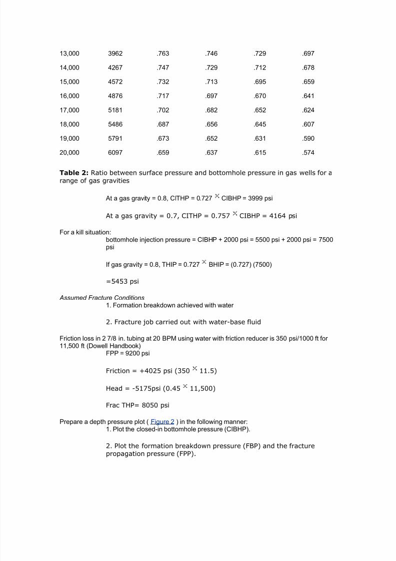
7242019 Completion Equipment
httpslidepdfcomreaderfullcompletion-equipment 1184
Figure amp
bull the most seere burst and collase loadings occur during ressure testing
-ell 6ill and stimulation
bull the most seere collase loading occurs do-nhole
bull additional annulus ressure can be used to reduce burst loading roided
the casing is strong enough
bull the tubinghead ressure during 6ill oerations (THIP) often aro1imates or
e1ceeds the reseroir ressure (I2HP)
Cith relatiely sall tubing strings (5 in or 3 the inherent burst and collapse strength isso high that soe engineers do not bother ampith tubing design in ampells ampith depths of less than ft 25 3 unless oerpressures are expected
Simplified Tensional Strength Design
Although burst and collase resistance ma not be significant considerations inuming -ells tensional strength is a critical design arameter for all -ells ouling
lea6age and failure -hich accounts for 0 of the roblems in -ell tubulars often
7242019 Completion Equipment
httpslidepdfcomreaderfullcompletion-equipment 1284
ma be the result of inadeuate tensional design rather than a burst or sealingroblem In this resect it is articularl imortant to remember that test ressures
imose substantial iston forces on the tubing (eg a 000 si (3 Pa) ressuretest on a lug set inside in (3mm) tubing -ill increase the tension on the
hanger b (000)( 4)(44l) E 30 lb (4 6amp)
It is also imortant to recogni+e that unli6e other strength arameters the API 8ointstrength is based on a failure condition rather than the onset of lastic deformation
The failure condition is either an un+iing of the in and bo1 in the case of APIthreads because of ielding (also called 8umout)D or brea6age of reduced cross
section at the threads in the case of suare threads
ltinall there are all sorts of additional tensional loads that -e do not normallanal+e in detail (eg shoc6 loading and drag forces during running bending
stresses buc6ling crosssectional iston forces changes in buoanc)
ince it is common ractice to ma6e a reliminar tensional design using tubing
-eight loading onl a higher design factor is used for tension and eseciall for 8oint
strength (Table 1 aboe) ome comanies and more conseratie engineers -illeen ignore the otential benefits of buoanc 2uoanc results in a iston force onthe lo-er end of the tubing and as a first aro1imation it ma normall be assumed
that
12amphere
CB buoyant ampeight
=amp E -eight in air
E densit of steel ( gmcc)
E densit of fluid
8igure 5 graphically depicts the tensional and copressional forces at ampork on a tapered string of tubular goods $he load resulting fro the ampeight of the pipe is shoampn for a string ampeighed in airand ampith the buoyant forces accounted for as piston forces or approxiated using EFuation 12Ce can see that at a point approxiately idampay in the length of the heaier pipe at the bottoof the string there is a change fro copression to tension $his is also the concept amphich guidesthe design of drillstrings ampith the purpose of keeping the drillpipe in tension amphile using theheaier drill collars to aintain a copressional load on the bit
Part of gt1amle gies the reliminar tension design considerations for thecomletion alread coered in art
Example 2 (part 2
reliminary Tension Design
7242019 Completion Equipment
httpslidepdfcomreaderfullcompletion-equipment 1384
$ubing ampeight 9gt lb7ft
Tubing length 00 ft
Pac6er fluid inhibited oil
03 sift E 0 gmcc
=amp E 4 00E 300 lb
E 0 300
E 04 lb
Joint Specifications
)55 lt
EGE H4 EGE H4 5
PI Aoint strengthKlb3
6 1 1(5 12
4esign factorTable 13
1 1 1 1
4esign capacityKlb3
55gt 559 655 611
Tubing Tension Design Considerations 1 eFuires lt tubing at surface
7euires 8oint strength caabilit of gtKgt or euialent
3 In ie- of ressures deth and H -ould robabl select remium
grade couling
any copanies hae these design techniFues prograed for the coputer and use the saegeneral techniFue for both tubing and casing designs
Tubing Design Parameters
It is imortant to remember that -hile the rimar function of the tubing is as aconduit for hdrocarbon roduction or for in8ection of -ater or gas the most seere
loadings often occur during -ell serice or 6illing oerations or during ressuretests It is therefore rudent to ma6e roision for these oerations -hen designing
a comletion and to chec6 out the tubing limitations -hen lanning a -ell sericingoeration (eg a stimulation or a -or6oer) are must be ta6en not to increase
comletion costs e1cessiel b tring to ma6e roisions for all sorts of unli6el butossible occurrences It must also be remembered that there are stes that can be
7242019 Completion Equipment
httpslidepdfcomreaderfullcompletion-equipment 1484
ta6en to mitigate the induced stresses during man oerations (eg alingannular ressure or heating fracturing fluids) Ln the other hand the conseuential
costs of a failed tubing string or of haing to run a secial -or6ing string in termsof deferred roduction and rig time can be uite substantial Assessment of the
most cost effectie solution is generall a 8udgment call based on the engineer5se1erience and on cororate attitudes and olic A tical set of arameters has
alread been illustrated in gt1amle
urst
The tubing and -ellhead should be designed for suee+e and 6ill conditions incefines in the erforations or oil can sometimes cause a chec6 ale effect -hen
attemting to suee+e bac6 liuids man comletion designers li6e to hae thefle1ibilit of being able to raise the bottomhole ressure to the lt2P or at least to the
ltPP Ho-eer -ith high ermeabilit reseroirs or gas -ells in -hich fracturestimulation is unli6el comletion engineers are often satisfied -ith a certain
minimum differential for in8ection The alue selected aries from area to area andfrom coman to coman but is commonl either around 000 si ( Pa) or 33
of the reseroir ressure The author suggests
1 8BP amphere k1 1 d kg 5 d
ltPP for suee+ing liuids -here 6 00 md
3 I2HP F 000 si ( Pa) for suee+ing gas -here6g 0 mdD or for suee+ing liuids -here 6 000 md
8ro the rock echanics theory presented by eertsa 163 and others it ay be deducedthat in a tectonically relaxed area a proisional estiate of the fracture propagation gradient8P3 can be obtained fro the eFuation
13
ltPM N lt2M N sift ( 6Pam) 1
amphere s oerburden stress J1 psi7ft depth3
E ore ressure si
G E deth ft
ltPM E formation roagation gradient sift
lt2M E formation brea6do-n gradient sift
$he specification of the pressure test conditions is often critical to burst design oernentregulations soeties specify pressure test conditions eg to at least 0 of the reseroirpressure or to 1 psi 5 Pa3 oer the axiu differential pressure expected at the packer3If no regulations exist ost operators test to their tubing design conditions
7242019 Completion Equipment
httpslidepdfcomreaderfullcompletion-equipment 1584
$ollapse
eere collase loads on the tubing can occur
bull in gas ampells and high oil ampells ampith loamp-floamping botto-hole pressures and deep-set safety ales after bloampdoampn to test a plug etc
bull during annulus ressure tests or oeration of shear circulation deices
bull -here there are ressured annuli
bull during underbalance erforating or testing at high dra-do-n
bull during tubing blo-outs
It is iportant to reeber that tension reduces collapse strength $his biaxial effect should beexained for large diaeter tubings especially if reduced collapse design assuptions and7or adeep-set safety ale is used
Tension
Tubing strings are not onl sub8ected to running tensions -ith all the associatedshoc6 and acceleration loadings but also to aring oerating stresses due to iston
forces on the steel andor an lugs ums standing ales and the li6e in thetubing oreoer if the tubing is anchored or held b a ac6er its oerating tension
-ill ar as a result of
bull theral effects hot production or cold kill fluid3
bull iston effects (changes in buoanc and forces at 8oint usets)
bull ballooning effects (changes in internal or e1ternal ressure)
bull buc6ling effects (longitudinal instabilit)
$hese potential probles are listed in ters of their ost coon relatie agnitude althoughthe relatie iportance of piston and ballooning effects is ariable3
$ombined oading
=hile the designer of tubular goods normall tal6s in terms of burst collase and
tension comression as if the -ere indeendent it is obious that in most actualloading situations the occur simultaneousl Precise stress analsis should reallconsider a tria1ial loading situation
The simultaneous solution of all the associated euations is rather comlicated Anumber of comuter rograms are aailable but for most field engineers the -ill be
a blac6 bo1 solution This can be dangerous It is imortant to chec6 that theformulas are roerl handled articularl -ith resect to collase -hich is a
stabilit effect Therefore it is usual for critical stress analses (eg for ultra dee
7242019 Completion Equipment
httpslidepdfcomreaderfullcompletion-equipment 1684
high ressure or sour -ells) to be underta6en b a secialist consultant researchgrou or intracoman tas6 force oreoer since this is not the routine design
techniue design factors are less -ell roen (although a alue of is oftenused)
A more conenient aroach for the intermediate range moderatel comle1 design
roblem is to use the ellise of bia1ial ield stress roosed b Holmuist and ampadai(3) The critical relationshis are (a) tension reduces collase resistanceD (b)comression reduces burst resistance
The other imortant concet in the consideration of tria1ial loads is that ressurechanges affect a1ial stresses or cause tubing moement This has been e1tensiel
discussed in Pgt aers b $ubins6i () Hammerlindl () and tillebroer()
ending
2ending stresses can be significant in large tubulars The are comressie in the
inner -all and tensional in the outer -all the most detrimental being
1ampamphere
the radius of curature ft3
sb E bending stress
gt E Ooung5s modulus (for steel gt E 30 0 si)
do E outside diameter of the tubular
Bending stresses result fro both hole curature and buckling $he effects of doglegs need onlybe considered if they are ery seere 1L71 ft= 1L7( 3 or if ery large tubing 5 172 to 6 in=1gt to 16 3 is being used
Production Casing
The roduction casing must be adeuatel si+ed for the lanned comletion It -illobiousl affect the si+e of the other reuired casing strings the bit selection the
caacit of the rig and the oerall -ell costs The roduction casing must bedesigned for the loads that ma be imosed during the roducing life of the field It
is similar to tubing design in seeral -as
urst
Production casing must be designed to -ithstand the ma1imum closedin tubing
ressure that can be e1ected If a ac6er has been used this ressure is assumed
to be alied at the to of a full column of ac6er fluid (ie for the case of a tubing
7242019 Completion Equipment
httpslidepdfcomreaderfullcompletion-equipment 1784
failure at the surface) =e usuall assume that the e1ternal ressure resisting burstis a -ater gradient If the ac6er fluid is heaier than -ater the burst load -ill
increase -ith deth
In the eent that a snubbing oeration could not be conenientl attemted if atubing brea6 occurs at the surface the casing must be strong enough to -ithstand a
bullhead suee+e on the lie tubing string in -hich case this -ould be the designcriteria for the casing and -ellhead
In man cases it ma be necessar to design the casing for loads imosed during
stimulation and ressure testing onersel the casing caacit must be chec6ed-hen designing a fracturing treatment This is articularl imortant in -ells -here
no ac6er is used
$ollapse
Production casing ma be sub8ect to comlete eacuation during roductionoerations if the -ell is oerated on gas lift or umedoff or if the ac6er or
-or6oer fluid is lost into a deleted +one As the ie ma hae deteriorated beforethis occurs a higher design factor (F) is often used for roduction casing
eere collase loads ma occur in situations in -hich thermal e1ansion of theannular fluid bet-een the roduction and intermediate strings cannot be bled off
(eg in some subsea -ells)
Increased loading should be assumed if lie annuli are a feature of the area 7educed
loadings ma be assumed if the -ells -ill not be umed off gas lifted or seereldeleted
eere collase loads ma e1ist in the a section during high dra-do-n
underbalanced erforating and testing and suee+e either or both cementation andfracturing ( ltigure $ollapse loads in the pay ) It is highl adisable to maintainsome set casingtubing annulus ressure during such serice oerations
7242019 Completion Equipment
httpslidepdfcomreaderfullcompletion-equipment 1884
Figure 1
Tensionamp$ompression
In high rate roduction areas and thermal -ells e1ansion of the roduction tubingma imose additional tension on the casing strings ia the ac6er
$ouplings
In high ressure (000 siD 34 Pa) high temerature (300B ltD 4 ) andor
seerel sour conditions remium casing coulings are recommended
aterial Selection
In sour enironments material secification must consider the chances of Hcontamination of the casingtubing annulus and the added ossibilit of temerature
changes during stimulation affecting the stress corrosion tolerance of the ie
Couplings
There are man forms of couling aailable some of -hich hae been dedicated tothe ublic through the ausices of the API -hile others are roduced b or under
7242019 Completion Equipment
httpslidepdfcomreaderfullcompletion-equipment 1984
license from a secific manufacturer It -as in fact the need to obtain astandardi+ation of thread forms and diameters that led to the formation of the API
ommittee on tandardi+ation of Tubular Moods in 4
The API coulings ( ltigure
Figure 1
ltigure and ltigure 3
7242019 Completion Equipment
httpslidepdfcomreaderfullcompletion-equipment 2084
Figure 2
$utaways of basic types of couplings) are of three basic tes e1ternal uset (gtKgt)
nonuset (ampK) and integral 8oint
7242019 Completion Equipment
httpslidepdfcomreaderfullcompletion-equipment 2184
Figure 3
Threads are of t-o main forms The round API threads are -ea6er than the ie
bod (ie N00 efficient) The buttress threads -ere deeloed b the ampationalTube Giision of the Knited tates teel ororation to roide a high strength
couling for dee high ressure -ell serice This thread is used in a number ofrorietar coulings eg Hdril A Atlas2radford
All taered threads achiee a seal b driing the in and bo1 surfaces together undersufficient stress to generate a bearing ressure e1ceeding an differential that is to
be subseuentl alied Ho-eer a small siral oid is al-as left bet-een themating surfaces and must be filled -ith solids in the form of thread comound (This
is the reason for careful secification of the comound in 2ul A) Ln API roundthreads this oid occurs bet-een the crest and root of the mating threads -hile on
buttress threads it e1tends oer the -hole flan6 of the thread on the beeled side
To imroe lea6 resistance eseciall at eleated temeratures and under high
ressure differential the socalled remium seals -ere deeloed These consist of either metaltometal seals on taered ortions of the in and bo1 surfaces or an
elastomer seal ring or both This te of seal reuires a high ualit finish andrecise gauging and insection The couling is therefore more costl ince API and
7242019 Completion Equipment
httpslidepdfcomreaderfullcompletion-equipment 2284
buttress threads hae roen to be er reliable in the field the decision to use themore e1ensie remium seals reuires careful economic 8ustification In general
their alication has roen aluable in highl corrosie conditions in high ressuregas -ells or high ressurehigh ML7 oil -ells and in thermal -ells sub8ect to high
comressie loads The ma be used -here -or6oer costs are high (egoffshore) In general API tubulars are adeuate for differential ressures of less than
000 si (344 Pa) and temeratures of less than 300B lt (0B ) using hightemerature thread comound ltor corrosie conditions and continuous gas sericethe ressure limit is often reduced to 00 si ( Pa)
gt1ercises
)ilfield nits
The in 4 lbft J ampK tubing string in a 000ft oil -ell -as designed
based on the tubing5s buoant -eight in -ater =hat additional load -ould beimosed on the tubing if a rod um -ere to be ressure tested to 00 si after the
-ell had been oerating for some time and the annulus umed offQ The -ell
roduces 30B API oil (M 0) -ith no -ater
If coman olic dictates the use of a design factor of for 8oint strength can
this ressure test be safel carried outQ
SI nits
The 3mm ( in) 6gmm (4 lbft) J ampK tubing string in an 30moil -ell -as designed based on the tubing5s buoant -eight in -ater =hat additional
load is imosed on the tubing if a rod um -ere to be ressure tested to 3 Paafter the -ell had been oerating for some time and the annulus umed offQ The
-ell roduces 6gm3 oil (M 0) -ith no -ater
If coman olic dictates the use of a design factor of for 8oint strength can
this ressure test be safel carried outQ
olutions
)ilfield nits
=eight in air E 000 ft 1 4 E 3400 lb
2uoanc in -ater E E 0
(densit of -ater gmccD densit of steel E gmccD use gtuation )
12
7242019 Completion Equipment
httpslidepdfcomreaderfullcompletion-equipment 2384
Buoyant ampeight amphen run (gt x 65 ((9 lb
=ater gradient (M E ) E 0433 sift
Lil gradient (M E 0) E 0 1 0433 E 03 sift
IG of tubing E 44 in Ai E 40 in
=eight of oil in tubing E 000 1 03 1 40 E 04 lb
Total alied tensile force at the surface after -ell has been umed off euals
Ceight of oil ampeight of tubing in dry casing applied pressure x area of tubing I4 19gt2 (gt 5 gt93 19gt2 (gt 2(gt 51(2 lb
The API 8oint strength rating of in 4 lbft J nonuset tubing E 00lb
If a design factor of for 8oint strength is dictated b coman olic the
allo-able tensile loading (-ith design factor) E (00) ()E 4400 lb
Therefore the roosed loading e1ceeds the design secifications and a lea6 mightoccur during the test In fact the loading e1ceeds design secs een -ithout adding
the 00 si of -ellhead ressure (actual load 404 lb comared -ith an allo-ableof 4400 lb) Ho-eer using a 33 design factor for oerating loading conditions
ressure tests of u to 4 si -ould be ermissible
6293 1((3 19gt2 (gt pt gt93
Pt E 4 si
+ nits Ceight in air 1( x 5 16(5 kg 165 kM
2uoanc factor in -ater E E 0
(densit of -ater E gmccD densit of steel E gmccD use gtuation )
12Buoyant ampeight amphen run 165 x 65 1gt2 kM
=ater gradient (M E 0) E 4 6PamLil gradient (M E 0) 0 1 4 E 6Pam
7242019 Completion Equipment
httpslidepdfcomreaderfullcompletion-equipment 2484
IG of tubing E mm thus Ai E 30 1 l04 m
=eight of oil in tubing E (30 m) ( 6Pam) (30 1 03 m)E 44 6amp
Total alied tensile force at the surface after -ell had been umed off euals
Ceight of oil ampeight of tubing in dry casing applied pressure x area of tubing I4 gt6gt 165 (5 (1 x 1 -(3 gt6gt 165 156 22gt6 kM
8ro 8igure 1 the PI Aoint strength rating of 6(- 5 kg7 )-55 nonupset tubing is
629 lbs (222 kM3
Figure 1
If a design factor of for 8oint strength is dictated b coman olic the
allo-able tensile loading (-ith design factor)
(222715 2152 kM
7242019 Completion Equipment
httpslidepdfcomreaderfullcompletion-equipment 2584
$herefore the proposed loading exceeds the design specifications and a leak ight occur duringthe test In fact the loading exceeds design specifications een at ero ampellhead pressure actualload of gt6gt 165 216 kM copared ampith an alloampable load of 2152 kM3
Ho-eer using the 33 design factor for oerating loading conditions ressure tests
of u to 6Pa -ould be ermissible
216 pt (1 x l-gt3
t E 4 6Pa
2 )ilfield nits 12-ft hydrostatically pressured gas ampell γ g 63 is to be copleted Chat closed-in tubing
head pressure can be expectedN If the casing ampellhead and tubing are to be designed for asFueee kill at fracture propagation pressure 8PP3 amphat ampellhead pressure ampould be expected atthe start of the kill operationN Gse EFuation 1( for estiating the 8P3
13
+ units (99- hydrostatically pressured gas ampell γ g 63 is to be copleted Chat closed-in tubinghead pressure is expectedN
If the casing -ellhead and tubing are to be designed for a suee+e 6ill at fractureroagation ressure (ltPP) -hat -ellhead ressure -ould be e1ected at the start
of the 6ill oerationQ (Kse gtuation 3 for estimating the ltPM)
olutions
)ilfield nits
Condition Loading Design Criteria Typical Design Factor
Burst Internal Kill pressure on
hydrocarbon-filled tubing
1125
External Packer fluid and eroannulus pressure
onsiderations heck effects ofcopression
ollapse External asing head pressure 1125
7242019 Completion Equipment
httpslidepdfcomreaderfullcompletion-equipment 2684
shut-in tubing pressure
Internal $ubing epty anddepressured
onsiderations heck effects of tension
$ension unning Buoyant ampeight in Body 1(((
copletion fluid )oint 1+
$ension andopression
perating old stiulation and hotproduction conditions
Body 1125
)oint 1(((
onsiderations heck effects ofteperature andpressure changes
$otal tress $riaxial ax stress 0 yield
CAssuming searate chec6s are not lanned on shoc6 and bending effectsD other-iseuse
Table 1 Typical criteria for tubing design on a flowing well
The ratio of THP to 2HP for γ g of 0 E 04
At 000 ft assuming a hdrostatic gradient of 0433 sift the bottomholeressure can be estimated as
BP 12 x gt(( 519 psiampith gas surface pressure 519 x 6gt6 I$P (1 psi
Assuming the oerburden gradient to be sift and using gtuation 3 to estimate
the fracture roagation ressure
E 0 sift
ltPP E 0 000 ft E 04 si
axiu ampellhead pressure at the start of the kill operation $IP3 ampill eFual the forationpropagation pressure inus the pressure due to the gas gradient
7242019 Completion Equipment
httpslidepdfcomreaderfullcompletion-equipment 2784
$IP 12 6163 - 519 - (13 62 psigore correctly ampe should use the ratio in Table 1 since the increased pressure ampill increase thegas density
$IP 12 6163 6gt6 9gt26 psi$herefore a 5 psi ampellhead should not be used een though the axiu closed-in tubinghead pressure is only about gt psi
SI nits
7eferring to Table 1
The ratio of THP to 2HP for γ g E 0 E 04
At 30 m assuming a normal hdrostatic ressure of 6Pa m bottomholeressure can be estimated as
BP (99 65 (55 kPa
ampith gas surface pressure (55 6gt6 I$P 296 kPa
Assuming the oerburden gradient to be 6Pam and using gtuation 3 toestimate the fracture roagation ressure
E 6Pam
ltPP E 30 E 3 6Pa
axiu ampellhead pressure at the start of the kill operation $IP3 ampill eFual the foration propagation pressure inus the pressure due tothe gas gradient
THIP E (30 ) (30 0) E 0 6Pa
ore correctly ampe should use the ratio in Table 1 since the increased pressure ampill increase thegas density
$IP (99 19213 6gt6 gtgt(1 kPa
9gt Pa ampellhead should therefore be used
3hellip)ilfield nits
A 000ft -ell that is to be roduced -ith a target of 000 T2d using intubing encounters 0 ft of oilbearing formation -ith a ressure of 3000 si =hat
rating of -ellhead should be usedQ If a single grade and -eight of tubing is to be
7242019 Completion Equipment
httpslidepdfcomreaderfullcompletion-equipment 2884
used -hat is the cheaest string that can robabl be run assuming that
Grade -eight lbft
Collapse
+trength psi
urst
+trength psi
Tensional
+trength 1 lb
Cost Coparison
)-55 155 gtgt gt1 ( cheapest
16 gt1 5(2 (2
-65 16 96 625 gt2( ost expensie
M- 16 92 66gt gtgt9 oderately expensie
2 ( 52gt
ac6er fluid inhibited sea-ater (gradient E 043 sift)
reseroir ressure 3000 si
6ill ressure 000 si aboe I2HP (suee+ing gas)N fracture roagation ressure (suee+ing oil)
ltracture roagation ressure gradient (ltPM) is aro1imatel
8P 5 5 psi7ft3
If gas cap gas should break through into the ampell assue gas graity 95
Kse Table 1 to calculate head of gas
Condition Loading Design Criteria Typical Design Factor
Burst Internal Kill pressure onhydrocarbon- filledtubing
1125
External Packer fluid and ero
annulus pressure
onsiderations heck effects ofcopression
ollapse External asing head pressureshut-in tubing pressure
1125
Internal $ubing epty and
7242019 Completion Equipment
httpslidepdfcomreaderfullcompletion-equipment 2984
depressured
onsiderations heck effects of tension
$ension unning Buoyant ampeight incopletion fluid
Body 1((( )oint 1+
$ension andopression
perating old stiulation and hotproduction conditions
Body 1125)oint 1(((
onsiderations heck effects ofteperature andpressure changes
$otal tress $riaxial ax stress 0 yield
CAssuming searate chec6s are not lanned on shoc6 and bending effectsD other-iseuse
Table 1 Typical criteria for tubing design on a flowing well
Assume lie oil gradient is 03 sift
onsider onl the ma1imum burst at the -ellhead the ma1imum collase load at theac6er and the running tension
SI nits
A 30m -ell that is to be roduced -ith a target of 400 m3da of oil -ith l40mm ( inch) tubing encounters 0 m of oilbearing formation -ith a ressure of
000 6Pa =hat rating of -ellhead should be usedQ If a single grade and -eight oftubing is to be used -hat is the cheaest string that can robabl be run assuming
that
Grade -eight
$gmm
Collapse
+trength
$Pa
urst
+trength
$Pa
Tensional
+trength
$amp
Cost Coparison
)-55 2(1 2655 ((19gt 1((gt cheapest
25( ((5( (99 1gt9(
-65 25( gt151 gt6 12 ost expensie
M- 25( gt(2 5((95 1gt oderately expensie
2 9 91gt 2((1
7242019 Completion Equipment
httpslidepdfcomreaderfullcompletion-equipment 3084
ac6er fluid inhibited sea-ater (gradient E 40 6Pam)
reseroir ressure 000 6Pa
6ill ressure 000 6Pa aboe I2HP (suee+ing gas)N fracture roagation ressure (suee+ing oil)
ltracture roagation ressure gradient (ltPM) is aro1imatel
8P 53 22(3 5 kPa7If gas cap gas should break through into the ampell assue gas graity 95
Kse Table 1 to calculate head of gas
Assume lie oil gradient is 6Pam
onsider onl the ma1imum burst at the -ellhead the ma1imum collase load at the
ac6er and the running tensions
olution
)ilfield nits
I$P IBP - o 4
o ( psi7ft
under operating conditions I$P ( - ( 63 psi
under axiu conditions assuing gas breakthrough3
ITHP E 04 1 2HP (from Table 1)
AR ITHP E 04 1 3000 E si
under 6ill conditions
8P 5 5
5 5 x 61 psi7ft
ltPP E 000 0
E 000 si
7242019 Completion Equipment
httpslidepdfcomreaderfullcompletion-equipment 3184
O BIP oil kill3
5 psieFuialent $P oil kill3
5 - ( x 6 2 psi
In the case of a gas kill
Iamp 2HIP(gas 6ill)
( 1 psi gt psi
eFuialent $P gas kill3
5gt x BP 5gt x gt (gt19 psi
8ro this ampe see that amphile ampe could probably get aampay ampith a ( psi ampellhead strictlyspeaking ampe should be using a 5 psi ampellhead
Incororation of the roision in some regulations for a -ellhead rating euialent
to the reseroir ressure reflects this tical design for 6ill caabilit
Tubing urst (ating
burst rating E ma1 THP design factor
design factor E
reuired burst rating (for gas 6ill conditions) E 34 E 343 si
All grades and -eights satisfactor
Tubing Collapse )oading Calculation
alculate first assuming a high ris6 of gas brea6through
head of packer fluid f 3 43 gt(53 63 (gt5 psi
ma1 HP E ma1 ITHP (assumes lea6)E si
ma1 2H annulus ressure E F 304E 0 si
7242019 Completion Equipment
httpslidepdfcomreaderfullcompletion-equipment 3284
ma1 collase load E 0 0 si (assumes emt tubing)E 0 si
design factor E
reuired collase rating E 0 1 si
E 30 si
$herefore strictly speaking ampe should use 2-lb7ft M- tubing although it is ore likely a l6-lb7ft ampould be selected since the probability is ery loamp that such seere collapse-loadingassuptions ampould proe true
alculate ne1t assuming a lo- ris6 of gas brea6through
ax P operating I$P
oerating ITHP E 00 si
ma1 2H annulus ressure E 00 F 304 siE 34 si
ma1 collase load E 34 si
reuired collase rating E 34 E 443 si
Ce could select 16 lb7ft )-55 tubing
(unning Tension Calculations
ampeight in air C 4 16 lb7ft3 6 ft3 11 lb
buoyancy factor
625
buoant -eight of tubing E 0 000 lb
E 04000 lb
design factor E
reuired tension rating E (04000) () lb
16 lb$his can be easily carried by any of the tubing grades listed
7242019 Completion Equipment
httpslidepdfcomreaderfullcompletion-equipment 3384
It is tical for collase design to be the critical factor in highrate largetubingcomletions eseciall at relatiel shallo- deths
Conclusion
in 0lbft amp0 tubing meets all criteria for this te of roduction 7is6 of
gas brea6through must be accuratel assessed before choosing bet-een amp0 and J grades
SI nits
I$P IBP - ρo x 4
ρo 969 kPa7
under operating conditions I$P 26 - 969 x 21(3
92gt9 kPaunder axiu conditions gas breakthrough3
ITHP E 04 1 2HP (from Table 1)
AR ITHP E 04 1 000 E 6Pa
under 6ill conditions
8P 53 22(3 5
53 22(3 5
19 kPa7
ltPP E (30) (00)
E 3400 6Pa
O BIP oil kill3 (gt kPa eFuialent $P oil kill3 (gt - 969 x 21(3
1929 kPa
In the case of a gas 6ill
Iamp 2HIP
(gas 6ill) E 000 F 000 6Pa
266 kPaeFuialent $P gas kill3 5gt x BP
5gt x 266 2(959 kPa
8ro this ampe see that amphile ampe could probably get aampay ampith a 26 Pa ampellhead strictlyspeaking ampe should be using a (gt5 Pa ampellhead
7242019 Completion Equipment
httpslidepdfcomreaderfullcompletion-equipment 3484
Incororation of the roision in some regulations for a -ellhead rating euialentto the reseroir ressure reflects this tical design for 6ill caabilit
Tubing urst (ating Calculation
burst rating E ma1 THP 1 design factor
design factor E
reuired burst rating (for gas 6ill conditions) E 3 1
E 3 6Pa
All grades and -eights satisfactor
Tubing Collapse )oading
alculate first assuming high ris6 of gas brea6through
head of packer fluid ρf 3 43
gt3 21(3 25 kPa
ax P ax I$P assues leak3 1696 kPa
ma1 2H annulus ressure E F 0
E 33 6Pa
ma1 collase load E 33 0 6Pa (assumes emt tubing)
E 33 6Pa
design factor E
reuired collase rating E 33 1 E 434 6Pa
Therefore strictl sea6ing -e should use a 6gm amp0 tubing but moreli6el 36gm tubing -ould be selected since the robabilit of such seere
collase loading is er lo-
alculate ne1t assuming lo- ris6 of gas brea6through
ax P operating I$P
oerating ITHP E 4 6Pa
ma1 2H annulus ressure E 4 F 0
E 0 6Pa
ma1 collase load E 0 6Pa
7242019 Completion Equipment
httpslidepdfcomreaderfullcompletion-equipment 3584
reuired collase rating E 0 1 E 300 6Pa
Ce could select 25(-kg7 )-55 tubing
(unning Tension Calculation
ampeight in air 25( 21( 5( kg 525 kM
buoanc factor E
EE0
buoant -eight of tubing E 0 6ampE 4 6amp
design factor E
reuired tension rating E (4) ()
E 30 6amp
$his can be easily carried by any of the tubing grades listed
It is tical for collase design to be the critical factor in highrate largetubing
comletions eseciall at relatiel shallo- deths
Conclusion
40mm ( inch) 36gm 0 tubing meets all criteria for this te ofroduction 7is6 of gas brea6through must be accuratel assessed before choosing
bet-een 0 and J grades
Pac6ers
Pac$er unctions
A ac6er is a subsurface tool that roides a seal bet-een the tubing and
casingthereb reenting the ertical moement of fluids across this sealing oint
Pac6ers are used for the follo-ing reasons
9 to imroe safet b roiding a barrier to flo- through the annulus
7242019 Completion Equipment
httpslidepdfcomreaderfullcompletion-equipment 3684
9 to 6ee -ell fluids and ressures isolated from the casing
9 to imroe flo- conditions and reent heading
9 to searate +ones in the same -ellbore
9 to lace 6ill fluids or treating fluids in the casing annulus
9 to ac6 off erforations rather than use suee+e cementing
9 to 6ee gas lift or hdraulic o-er fluid in8ection ressure isolated from the
formation
9 to anchor the tubing
9 to install a casing um
9 to minimi+e heat losses b allo-ing the use of an emt annulus or thermal
insulator
9 to isolate a casing lea6 or lea6ing liner la
9 to facilitate temorar -ell serice oerations (eg stimulations suee+es)
Pac$er T+pes
There are man ac6er manufacturers some of -hom offer an e1tensie ariet ofac6ers -ith each differing to some degree from those of the other manufacturers
This rather be-ildering arra can ho-eer be groued into rincial classes or
tes and ma be further categori+ed b method of setting b direction of ressureacross the ac6er and b the number of bores through the ac6er
Pac6ers can be rimaril classified as either retrieable or ermanent or
ermanentretrieable or inflatable
)etrievable acers
This te of ac6er is run on the tubing ( ltigure )etrievable pacer )
7242019 Completion Equipment
httpslidepdfcomreaderfullcompletion-equipment 3784
Figure 1
After setting it can be released and recoered from the -ell on the tubing ince it is
an integral art of the tubing string the tubing cannot be remoed from the -ell-ithout ulling the ac6er unless a detachable ac6er head is used
7etrieable ac6ers ma be designed to be set mechanicall or hdraulicallechanical setting methods include rotation of the tubing string recirocation of the
tubing string or the alication of tension or setdo-n -eight =ith mechanical
ac6ers the tubing is usuall set in comression
Hdraulic ac6ers are set b aling hdraulic ressure through the tubing stringbut once set the hold the set osition mechanicall The tubing is usuall in tension
7etrieable ac6ers are usuall used for comle1 multi+one and multistringcomletions Their main limitation -as in their limited abilit to accommodate tubing
stress changes -ithout unsettingD the aailabilit of effectie sli 8oints anddetachable heads has eased this situation An historical roblem -as failure of the
internal elastomer seals but this technolog also has imroed mar6edl in the lastdecade All metaltometal seal ac6ers are aailable but are e1ensie
7242019 Completion Equipment
httpslidepdfcomreaderfullcompletion-equipment 3884
Lne disadantage of retrieable ac6ers is that if the fail to retriee the must beremoed b milling them out of the casing -ith an abrasie milling head and a
drillstring The are er difficult to mill Menerall this te of ac6er is used undernonseere conditions (differential ressures less than 000 si (344 Pa)
temeratures less than 300B lt (4B )
2ecause of the setting mechanism retrieable ac6ers tend to hae a restrictedbore comared -ith other ac6ers designed for the same casing si+e This factorma restrict flo- or limit -ireline oerations belo- the ac6er deth
ermanent acers
Permanent ac6ers are indeendent of the tubing and ma be run on tubing or on
-ireline ( ltigure and ltigure 3 )
Figure 2
The tubing can be released from the ac6er and can be ulled leaing the ac6er set
in the casing
7242019 Completion Equipment
httpslidepdfcomreaderfullcompletion-equipment 3984
Figure 3
Tubing can subseuentl be run bac6 and resealed in the ac6er The ac6er ma
thus be considered an integral art of the casing It is sometimes called either aroduction ac6er or a retainerroduction ac6er
The ermanent ac6er cannot be recoered as such but it can be destructiel
remoed (eg b milling) ( ltigure 4 and ltigure )
7242019 Completion Equipment
httpslidepdfcomreaderfullcompletion-equipment 4084
Figure 4
If the ac6er includes a tailie and must be recoered a millout e1tension is
needed on the ac6er for the ac6er ic6er or catch sleee on the mill to engageIn other cases it ma be adeuate to siml ush the ac6er to the bottom of the
casing after milling
7242019 Completion Equipment
httpslidepdfcomreaderfullcompletion-equipment 4184
Figure amp
Permanent ac6ers can be set using an electric -ireline setting tool a hdraulicsetting tool run on drillie or tubing or b a combination of rotation and ull
Permanent ac6ers are ticall used -hen
9 formation treating or s-abbing differential ressures -ill be high
9 it is desirable to ull the tubing -ithout unseating the ac6er
9 it might be desirable to conert the ac6er to a temorar or ermanentbridge lug
9 high bottomhole temeratures e1ist
9 tubing oerating stress ariations -ould not be accommodated -ith a
retrieable ac6er -ithout ma6ing it imossible to ull
9 a retrieable ac6er -ould hae an inadeuate bore
ermanent+)etrievable acers
7242019 Completion Equipment
httpslidepdfcomreaderfullcompletion-equipment 4284
A recent arrial this te of ac6er has the same characteristics as the ermanentac6er but it can -hen desired be released -ith a secial ulling tool and
recoered
nflatable acers
These are ac6ers -ith a fle1ible sealing element that can be e1anded hdraulicallusing either comletion fluid or cement The are used as oenhole ac6ers or -hen
the casing is buc6led or collased reenting the usage of conentional ac6ers
Inflatable ac6ers cannot stand high ressure differentials and are generall limited
to secial alications such as drillstem testing
acer -ailures
The ma8or causes of socalled ac6er failures relate to
9 use of the ac6er outside its oerating range
9 unsetting of the ac6er or seal assembl as a result of ressure ortemerature changes
9 using or setting the ac6er incorrectl
9 the ac6er being in oor condition -hen run
Gifficult oerating conditions reuire more e1ensie euiment and more rigorous
design -or6 It is imortant to remember that a ac6er is effectiel a iston -ithin
the casing and -ill therefore be heail affected b changes in differential ressurePressure from belo- or increasing string tension due to tubing contraction or both
tend to unset the follo-ing
9 -eightset ac6ers
9 hdraulicall set ac6ers not euied -ith holddo-n buttons
9 locator seal assemblies or oershots
Pressure from aboe tends to unset tensionset ac6ers or cause collasete
failures or lea6age at seal assemblies under high ressure differentials
Tubing0acer Forces and oveent
hanges in temerature and ressure inside and outside the tubing affect the lengthof the tubing string (if the string is designed to ermit motion) and the forces
e1erted at the ac6er (if no motion is ermitted)
These changes in tubing length or force bet-een roducing and umin conditions
can be large and should be considered in choosing a ac6er This is eseciallimortant in high temerature (usuall dee) -ells and ma limit the use of
7242019 Completion Equipment
httpslidepdfcomreaderfullcompletion-equipment 4384
retrieable ac6ers Gesign of sli 8oints and seal assemblies must also considerthese forces
(The follo-ing section dra-s heail on the -or6 of GJ Hammerlindl () and
Arco as ublished in T ltebruar and on that of Arthur $ubins6i = Althouse and T $ $ogan ())
actors Causing Pac$er orces or Tubing o-ement
If the tubing string is free to moe its length -ill change as a result of temeratureand ressure influences -hich ma be subdiided into thermal iston force
ballooning and buc6ling effects onsideration of these effects -ill determine theseal length reuired andor sli 8oint design
If the tubing is anchored to the ac6er these effects -ill result in a change In thea1ial tension in the tubing This can affect not onl the design of the uermost
tubing 8oint but also ac6er shear in rating and the degree of buc6ling aboe theac6er and therefore the throughbore access A mechanical force is also inoled in
this situation
To consider these effects it is necessar to define the critical conditions to be
e1amined These normall include
bull landing conditions=
bull oerating conditionsD
bull shutin conditionsD
bull 6illingstimulating conditionsD
bull ressure test conditions
Initial calculations are ade for a set of assued landing conditions eg -5 to 5 lb -225 to 225 kM3 tension -3 or copression 3 8or conenience adesigner ay soeties choose to exaine only the differences betampeen amphat are considered tobe the ost seere conditions ie hot producing to cold stiulating3= hoampeer these are notalampays apparent eg pressure test loads can be the ost seere3
ecanical orces
echanical forces can be subdiided into tension and comression Tension results in
the stretching of tubing string The elongation due to tension forces can bedetermined b Hoo6e5s la- -hich states that the change in length is directl
roortional to the alied force The euation for Hoo6e5s la- in this alication isas follo-s
1amphere
7242019 Completion Equipment
httpslidepdfcomreaderfullcompletion-equipment 4484
length change inches3 lt tubing length inches3 8t tensional force -3 lbf3 E HoungQs odulus ( 19 psi3
s cross-sectional area of the tubing ampall in23$his relationship is the basis of the tubing stretch tables and graphs published by arious
eFuipent anufacturers
Temperature or Termal Effects
The length change due to change in temerature is eual to the length of the tubing
times the coefficient of thermal e1ansion for steel times the change in aeragetemerature
ince
1then
1(amphere
change in tensional force in tubing at the surface due to teperaturechange
s the coefficient of theral expansion for steel β3 is 9 l-97L8 12gt2 l-97L3 and HoungQsodulus E3 is ( x 19 psi 26 Pa3
-26 s ∆$ lb7L8
ltt E As ∆T ampB
In ost cases it is adeFuate to deal ampith the change in the aerage string teperature It is oftenassued that
bull the copletion is at geotheral gradient amphen landed 1 to 2L 871 ft or 1 to (9L71 3
bull during stimulation6illing it -ill stabili+e -ithin 0B lt (0B ) of ambient
temerature
$he teperature during producing conditions is a function of floamp rate gas expansiongeotheral gradient theral insulation of the tubing and the like Rarious coputer prograsare aailable to calculate this in critical cases but it is usually adeFuate to use data fro offsets
producing under siilar conditions Production test data should be used Audiciously since testrates and floamp periods are often too loamp and too short for theral stabiliation to occur s a firstapproxiation designers ampill often assue a floamping gradient for high rate ampells of gt L871 ftor 6 L71
Piston orce Effects
The most familiar form of iston force is that of the stretch andor stress induced
-hen ma6ing an internal ressure test against a lug set inside a string of tubing
7242019 Completion Equipment
httpslidepdfcomreaderfullcompletion-equipment 4584
The force against the lug is eual to the ressure alied times the crosssectionalarea of the tubing IG
8p pt i 18or exaple a 1 psi 9 kPa3 pressure test on ( 172-in 3 tubing I4 22 in3should result in a force of
8p 1 2232 6 lb (11 M3
Chere the tubing is inserted into a packer ampe ust siilarly consider the piston effects on thecross section of the steel as it is affected by changes in the internal and external pressure
The iston force at the ac6er related to a change in the inside and outside ressures
is
8p p - i3 pi - p - o3 po 2amphere
p area of packer bore
Ai E area of tubing IG
Ao E area of tubing LG
$he change in tubing length related to this piston force is
21
amphere the pi and ∆po changes are considered positie if they correspond to an increase andnegatie if they correspond to a decrease in pressure 8igure 1 Schematic showing piston force
at the packer related to a change in the inside and outside pressures3
7242019 Completion Equipment
httpslidepdfcomreaderfullcompletion-equipment 4684
Figure 1
The iston forces are in essence the change in the buoant force on the tubing
allooning Effects
As the ressure inside the tubing increases the ie e1ands radiall This -ill cause
an a1ial shortening Alication of ressure to the annulus -ill cause the tubingdiameter to contract (reerse ballooning) This -ill result in a tubing elongation
The length change accounts for the change in radial ressure forces due to surface
ressure changes (∆is and ∆os) and fluid densit changes (∆ρi and ∆ρo) as -ell as
flo- inside the tubing (δ ) The formula for calculating the change in length due to
ballooning is
7242019 Completion Equipment
httpslidepdfcomreaderfullcompletion-equipment 4784
22amphere
PoissonQs ratio of the aterial for steel (3
7 E ratio LGIG of the tubing
δ E dro in ressure in the tubing er unit length due to flo- The
ressure dro is ositie -hen the flo- is do-n-ard and +ero -henthere is no flo-
ρi E densit of fluid inside tubing
ρo E densit of fluid outside tubing
is E surface tubing ressure
os E surface annulus ressure
ucling ffects
2uc6ling is caused b t-o effects alied longitudinal comression loads andinternal ressure
The first is eas to understand as a logical conseuence of the loading of a columnHo-eer the buc6ling of a ie under tension as a result of internal ressure is a
difficult concet to areciate Lne -a to isuali+e this te of buc6ling is toconsider a slightl bananashaed tubing 8oint sub8ect to internal ressure ( ltigure
and ltigure 3 $auses of bucling)
Figure 2
7242019 Completion Equipment
httpslidepdfcomreaderfullcompletion-equipment 4884
There -ill be a small unoosed area uon -hich the ressure -ill act to cause
distortion of the ie
Figure 3
The resulting buc6ling -ill reflect the balance of strain and bending energ This issimilar to haing a fictitious force (ltf ) acting on the end of the ie
To better understand buc6ling resulting from comression loading consider a stringof tubing freel susended inside the casing ampo- consider an u-ard force lt
alied to the lo-er end of the tubing This force comresses the string and buc6lesthe lo-er ortion of the string into a heli1 The neutral oint is -here the buc6ling
stos This force decreases -ith increasing distance from the bottom of the string
and becomes +ero at the neutral oint The distance n from the bottom of thetubing to the neutral oint is calculated from the follo-ing formula
23amphere
C Cs ρi i - ρo o representing the buoyed ampeight of the tubing per unit length 8 the force applied to the loamper end
It should be understood that in the presence of fluids the neutral point is not the point at amphichthere is neither tension nor copression but it is the point beloamp amphich the string is buckled andaboe amphich the string is straight
7242019 Completion Equipment
httpslidepdfcomreaderfullcompletion-equipment 4984
If the neutral oint is -ithin the string then the shortening of the string due to
buc6ling (∆$b) is as follo-s
24amphere I is the oent of inertia of tubing cross section ampith respect to its diaeter
I E (G4 d4)
=hen the calculated alue of the neutral oint is aboe the uer end of the string
the entire string buc6les into a heli1
=hen the ressure inside the tubing (P i) is greater than the ressure outside (o) at
the ac6er a shortening -ill occur due to helical buc6ling It -as determined b
$ubins6i Althouse and $ogan () that as far as the buc6ling is concerned thetubing behaes as if sub8ect to the follo-ing fictitious force
8f ppi - po3 2ampBecause part of this force 8f appears to be nonexistent the entire force 8 ampas gien the naefictitious 8urther it ampas deterined that the string ampould buckle if 8f is positie and ampould reainstraight if 8f is ero or negatie ubstitution into EFuation 2gt gies
2
amphere ∆ltb is the change in length ampith respect to the length of the tubing amphen landed ampith p i po
If the ressure outside the tubing is greater than the ressure inside the tubing atthe ac6er (o i) there is no helical buc6ling due to ressure
The total change in tubing length as a result of these arious factors (mechanical andiston forces and thermal ballooning and buc6ling effects) ma be e1ressed as
lt lt ltt ltp ltB ltb 2
$he effect of this net change in tubing length on the tubing stress ampill depend upon the aount ofotion peritted by the packer design
Permanent Cor$screing
If the buc6ling results in the ield strength of the tubing being e1ceeded ermanentcor6scre-ing can occur In addition to the stresses of helical buc6ling the tubing issub8ect to elongational stresses as -ell as tangential and radial stresses due to
ressure inside and outside the tubing A tria1ial stress analsis must be made -hereconditions suggest that significant tubing stress -ill result All the ma8or euiment
suliers hae comuter and hand calculator rograms aailable for ma6ing thesecomutations This serice is usuall aailable free to urchasers The roduction
engineer should send some time determining the ressure and temeratureconditions to be e1ected Ticall a series of calculations is made for arious
7242019 Completion Equipment
httpslidepdfcomreaderfullcompletion-equipment 5084
landing assumtions and the results lotted for analsis It is also useful to ma6e atleast one hand calculation as a crosschec6 on the data receied
gt1ercise
1 )ilfield nits
A 0000ft highrate oil -ell is comleted -ith in lbft tubing (-allthic6ness 0 in) Knder roducing conditions the flo-ing temerature gradient is
04 Bltl00 ft and under static conditions the geothermal gradient is Blt00 ftfrom a mean surface temerature of 40 Blt =hen the -ell is 6illed -ith a large
olume of 40 Blt sea-ater the bottomhole temerature dros to 0 Blt If free tomoe -hat tubing moement can be e1ected from the landing condition to the hot
roducing and to the cold in8ection conditionsQ If a hdraulic ac6er -ere to be usedand set in 30000 lb of tension -hat -ould be the tension loading on the ac6er
after 6illing the -ellQ (Kse gtuation and ignore iston ballooning and buc6lingeffects)
1(
+ nits
A 300m highrate oil -ell is comleted -ith 40mm 36gmm tubing (-allthic6ness E mm) Knder roducing conditions the flo-ing temerature gradient is
03 B00 m and under static conditions the geothermal gradient is 3 Bl00 mfor a mean surface temerature of 0 B =hen the -ell is 6illed -ith a large
olume of 0 B sea-ater the bottomhole temerature dros to 0 B If free tomoe -hat tubing moement can be e1ected from the loading condition to the hot
roducing and to the cold in8ection conditionsQ If a hdraulic ac6er -ere to be usedand set in 334 6amp tension -hat -ould the tension loading on the ac6er be after
6illing the -ellQ
(Kse gtuation and ignore iston ballooning and buc6ling effects)
olution
)ilfield nits
7eseroir temerature E 40 F ( 1 0000 S 00) E 0 Blt
Temerature loss u the tubing E 04 1 0000 S 00 E 40 Blt
ltlo-ing tubing head temerature E 0 40 E 0olt
ltrom landing conditions to roducing conditions
7242019 Completion Equipment
httpslidepdfcomreaderfullcompletion-equipment 5184
ltt lt3 β 3 $3
13 9 1-93 $3
amphere $
$anding E 30Blt
Producing E 00Blt
$ 2 - 1( 6L8
$t E (0000) ( 1 0) (0) E F43 ft
amphere 1 initial aerage teperature in tubing string
2 final aerage teperature in tubing string $surf surface tubing string teperature $B bottohole tubing string teperature
8ro producing to inAection conditions
Producing E 00 Blt
In8ection E Blt
$ 55 - 2 -1gt5L8
ltt lt3 β 3 $3 13 9 1-93 -1gt53 -1 ft
$herefore the axiu oerall length change is -1 ft fro producing to inAection
gtuation states the change in tension to be
8t -Eβ 3 s3 $3for tubing ampith 4 55 in and I4 gt5 in
gt51 in2
Betampeen landing and inAecting conditions the apparent force acting on the tubing to cause thecontraction effect is
7242019 Completion Equipment
httpslidepdfcomreaderfullcompletion-equipment 5284
8t -E3 β 3 s3 $3 -( x 193 9 1-93 gt513 55 - 1(3 616 lb force
$o aintain the original tubing length the packer ust exert an eFual and opposite force
8p -616 lb f tension3If the tubing ampas landed in ( lb tension the net tension at the packer leel is
8p -616 - (
lt E 000 lb force (tension)
$his is ampell in excess of feasible shear pin arrangeents and therefore a hydraulic packer cannotbe used $his ampell should be copleted ampith a peranent packer and a locator seal assebly ofseal receptacle peritting 1 ft of trael
SI nits
7eseroir temerature E F E 00 B
Temerature loss u the tubing (flo-ing) E
6( 22( L8loamping tubing head teperature 15 - 22( 26L
ltrom loading conditions to roducing conditions
ltt lt3 β 3 $3
(53 12gt2 l-93 $3
amphere $ 2 - 1
$anding E B
Producing E 3B
$ 2 - 1 ( - 55 (L
$t E (300) (4 1 0) (3) E 4 m
amphere
1 initial aerage teperature in tubing string
2 final aerage teperature in tubing string $surf surface tubing string teperature $B bottohole tubing string teperature
7242019 Completion Equipment
httpslidepdfcomreaderfullcompletion-equipment 5384
8ro producing to cold inAection conditions
Producing E 3B
In8ection E 30B
$ 2 - 1 1( - ( -L
ltt lt3 β 3 $3 (53 12gt2 1-93 -3 -(9
$herefore the axiu oerall length change is (9 fro production to inAection
gtuation states the change in tension to be
8t -Eβ 3 s3 $3for tubing ampith 4 1gt and I4 129
s 1gt2 - 12923 2 225 1-( 2
Betampeen landing and inAection conditions the apparent force acting on the tubing to cause thecontraction effects is
8t -E3 β 3 s3 $3 -29 193 12gt2 1-93 225 1-(3 1( - 553
8t (155( kM$o aintain the original tubing length the packer ust exert an eFual and opposite force
8p -(155( kM
If the tubing ampas landed in 1((gt5 kM tension the net load at the packer is 8p -(155( - 1((gt5
-gtgt kM tensile force$his is ampell in excess of feasible shear pin arrangeents and therefore a hydraulic set packercannot be used
This -ell should be comleted -ith a ermanent ac6er and a locator seal assembl
or seal recetacle ermitting 3 m of trael
Artificial $ift gtuiment
Ancors
Knanchored tubing in a rodumed -ell -ill be sub8ect to constant moement Thetubing -ill buc6le on the ustro6e and stretch on the do-nstro6e This is sometimes
called breathing This moement leads to -ear and fatigue roblems and can resultin inefficient use of the aailable uming unit stro6e Tubing anchors are used to
minimi+e this moement
Tubing anchors are classified as follo-s
7242019 Completion Equipment
httpslidepdfcomreaderfullcompletion-equipment 5484
9 tension anchors -hich ermit the tubing to elongate but not to shorten
9 comression anchors -hich ermit shortening but not elongation
9 fi1ed anchors
$ompression anchors reduce the breathing roblems but do not reent buc6ling and
are therefore rarel used Tension anchors -hich graduall -al6 do-n the inside of the casing as the um starts to oerate and then set the tubing at its ma1imum
elongation ma damage the casing b reeated slight moement Therefore mostanchors used toda are of the fixed te (often miscalled tension anchors) ( ltigure
Figure 1
echanically set anchor ltigure
7242019 Completion Equipment
httpslidepdfcomreaderfullcompletion-equipment 5584
Figure 2
Dual hydraulically set anchor and ltigure 3 Single hydraulically set anchor )
7242019 Completion Equipment
httpslidepdfcomreaderfullcompletion-equipment 5684
Figure 3
There are t-o main setting mechanisms
9 rotation set
9 hdraulic set
It is best to select an anchor -ith a bac6u retrieing mechanism so that if therimar one (ie rotation) fails a secondar release (ie shear ins) can be used
ome hdraulic anchors deend onl uon the differential ressure bet-een thetubing and casing These hae an additional alication in reenting seal assemblies
or ac6ers from becoming unlatched during stimulation oerations
ottohole 0ups
Getails of the bottomhole um for rodumed -ells are set out in API ec AR
-hich includes a character code to secif each um te The most critical isthe second grou -hich is the um bore ( to corresonding to 4 in to
34 in or 3 to 0 mm) and the um te (7rod and Ttubing)
7242019 Completion Equipment
httpslidepdfcomreaderfullcompletion-equipment 5784
The um dislacement in oil field units can be obtained from
P4 Ep 1199 Es M 42 2(amphere
stroke in3= say 6gt in Ep pup efficiency= assue 0
M pup rate= say 2 P Es stroke efficiency or rod stretch3= assue 0 4 pup bore= say 2 in M 15 in7inute axiu desirable for rod fall3
Gsing the nubers gien aboe the pup rate ampould be P4 gt6 B7d 6 (7d3
Go-nhole omletion Accessories
Seating ampipples
There are three main tes of seating nile used as integral arts of the tubing
string
9 umseating niles
9 selectie landing niles
9 nonselectie or nogo landing niles
eating niles -hich are used to accommodate a um lug hanger or flo-
control deice consist of a olished bore -ith an internal diameter 8ust less than thetubing drift diameter Ksuall a loc6 rofile is also reuired eseciall for landing
niles Hea dut tubing sections called flo- coulings are often run on eitherend of a seating nile to minimi+e the effects of turbulence ( ltigure anding
nipple and flow coupling installation)
7242019 Completion Equipment
httpslidepdfcomreaderfullcompletion-equipment 5884
Figure 1
eating niles and the deices that are set inside them are used for the follo-inguroses
9 to facilitate ressure testing of the bottomhole assembl and tubing
coulings and the setting of hdraulic ac6ers
9 to land and seal off a bottomhole um (um seating nile)
9 to isolate the tubing if it is to be run dr for high dra-do-n erforating
9 to land -ireline retrieable flo- controls such as lugs tubing safet ales
bottomhole cho6es and regulators
9 to lug the -ell if the tree must be remoed
9 to land bottomhole ressure bombs
9 to ac6off across blast 8oints
9 to install a standing ale for intermittent gas lift
7242019 Completion Equipment
httpslidepdfcomreaderfullcompletion-equipment 5984
9 to lug the tailie belo- ac6er in order to ull the tubing -ithout 6illingthe -ell
9 to temoraril lug the -ell -hile the rig is moed on or off the -ell
Selective anding ipples
electie landing niles are niles -ith a common internal diameter In some the
loc6 rofile is aried for eas identification ( ltigure
Figure 2
ltigure 3
7242019 Completion Equipment
httpslidepdfcomreaderfullcompletion-equipment 6084
Figure 3
ltigure 4 and ltigure anding nipples and locing mandrels)
7242019 Completion Equipment
httpslidepdfcomreaderfullcompletion-equipment 6184
Figure 4
Lthers are accessed b triing the loc6 mechanism at the selected deth
7242019 Completion Equipment
httpslidepdfcomreaderfullcompletion-equipment 6284
Figure amp
electie niles are used -hen more than one nile is reuired -ithin a single
string of tubing and the designer -ishes to maintain ma1imum throughbore Theshould be no closer than 30 ft (0 m) from a similar rofile and at least 0 ft (3 m)
from an change in diameter
o+Go anding ipples
ampogo landing niles are designed -ith an IG that is slightl restricted to roide aositie shoulder to locate a loc6ing mandrel The IG of these niles should be
chec6ed against the dimensions of an throughtubing euiment that ma be usedThis te of nile is usuall located at the bottom of the tubing string or tailie and
at least ft belo- an rofile change
In tailie installations it is best to include a sliding sleee aboe the nile in case
debris reents the ulling of an lug set in the nile b regular -ireline methodsAlternatiel a mechanical erforator ma be used to unch a hole aboe the lug
Sliding Slee-es
7242019 Completion Equipment
httpslidepdfcomreaderfullcompletion-equipment 6384
Also referred to as sliding side doors or circulating sleees these tubing comonentsare used to obtain access from the tubing to the tubingcasing annulus either for
fluid circulation or to ermit a reiousl isolated +one to be roduced ( ltigure Sliding sleeves) The are oened and closed -ith a -ireline tool that has a locating
6e that engages the rofile in the sleee A Tlt$ ersion is also aailable for subseacomletions
Figure 1
These deices are ticall laced aboe each ac6er in the -ell Lbiousl the are
an essential reuirement of multi+one comletions scheduled for selectieroduction an roducers run sliding sleees in each string in a multistring
comletion to increase roduction fle1ibilit
A sleee aboe the uer ac6er is articularl useful for the follo-ing oerations
9 6ic6off b dislacing the tubing contents -ith a lo- densit fluid therebaoiding the use of coiled tubing -ithin the tubing
9 -ell 6illing rior to a tubing ulling 8ob or -or6oer
7242019 Completion Equipment
httpslidepdfcomreaderfullcompletion-equipment 6484
9 circulating out comletion fluid -ith a ac6er fluid (eg from mud to brineor from -ater to inhibited brine)
9 testing of subsurface safet ale ()
9 temoraril roducing a selectie +one into the tubing so it can be tested or
so a bottomhole ressure sure can be obtained
The ualit of the elastomer seals in sliding sleees has imroed greatl oer the
last decade The are no- much easier to oen and less rone to failure ecialelastomers are needed for some -ell fluids and suitable design rocedures are no-
aailable for elastomers
A orted nile is sometimes used in lace of a sliding sleee although this ma6es it
necessar to ull the tubing string in order to sto annular access Alternatielsome comletion engineers refer to use a side oc6et mandrel and ale as a
circulation oint aboe the ac6er ampote ho-eer that side oc6et mandrels offer areduced area to flo- and restrict circulation rates
+ide 0ocet andrels
ide oc6et mandrels are a secial eccentric nile that can accommodate a ale in
arallel to the tubing to control access to the annulus ( ltigure Side pocetmandrels) The are used to install -ireline retrieable gaslift ales circulation
deices flo- control ales and in8ection ales
7242019 Completion Equipment
httpslidepdfcomreaderfullcompletion-equipment 6584
Figure 1
The location of side oc6et mandrels for gaslift ales -ill be determined b the lift
gas ressure aailable and 6ic6off reuirements
It is highl desirable to hae one or t-o mandrels located 8ust aboe the to ac6erin high ressure gas -ell comletions These are used to facilitate a controlled
circulation 6ill in the eent the sliding sleee is inaccessible or if corrosioninhibitor
in8ection is reuired Inhibitor ma be sulied either through the annulus or ia asecial control line continuousl or in batch treatments ome oerators also use
side oc6et mandrels to install a ressure and temerature sensor that can transmitdata to the surface ia a cable attached to the outside of the tubing
ome engineers refer to use a side oc6et mandrel instead of a sliding sleee aboethe to ac6er since the elastomer seals on a side oc6et circulation ale are easil
retrieed and redressed using -ireline -hile reair of those in a sliding sleeereuires a -or6oer Ho-eer most circulation ales hae a limited throughut
caacit (0 bm or m3 hr) and some oerators therefore hae a tendenc to ullthe ale to increase circulation caabilit This can result in a cutting out of the
ale seat in the mandrel -hich ineitabl reuires a -or6oer to relace themandrel
7242019 Completion Equipment
httpslidepdfcomreaderfullcompletion-equipment 6684
last 0oints and lo Couplings
2last 8oints and flo- coulings are secial 8oints haing the same nominal IG as thetubing but a greater LG The are usuall manufactured from secial heattreated
steel ( ltigure
Figure 1
last 0oints ltigure
7242019 Completion Equipment
httpslidepdfcomreaderfullcompletion-equipment 6784
Figure 2
olished nipples and ltigure 3 Schematic of polished nipple run to provide sealing
surface in case of blast 0oint erosion)
7242019 Completion Equipment
httpslidepdfcomreaderfullcompletion-equipment 6884
Figure 3
=hile the do not reent erosion from occurring their greater thic6ness can dela
the time to erosioncaused failures
last oints
2last 8oints are used to increase the abrasion resistance of the tubing string against
the 8etting action of a roducing formation 2last 8oints should be located in the
tubing string oosite all uer erforations sanned b the tubing 2last 8ointsshould also be used in the -ellhead area -here abrasie fracturing fluids ma be
umed into the casing access Polished niles are sometimes included in thetubing string on either end of a blast 8oint in order to roide sealing surfaces for a
sacer ie should the blast 8oint fail
-low couplings
ltlo- coulings should be run immediatel aboe each selectie or nogo landingnile in the tubing string that ma be used to locate a flo- control deice In high
rate or corrosie gas -ells flo- coulings should be used aboe and belo- all usetsor rofile changes to reduce erosion eseciall if the turbulent fluid contains abrasie
7242019 Completion Equipment
httpslidepdfcomreaderfullcompletion-equipment 6984
articles ince most flo- controls restrict the tubing IG the tubing aboe and belo-the controls should be rotected b use of a flo- couling
ubsurface afet ales (s)
Application of Donole Safet+ al-es
An must be installed in all offshore -ells caable of flo- and at onshore
locations in high ressure or sour gas -ells in close ro1imit to housing ublicroads or roc6 slide areas These reuirements are often dictated b goernment
regulations andor cororate olic
The ob8ectie is to roide a do-nhole shutoff that -ill limit the magnitude and
conseuences of the hdrocarbon emission if the rimar -ell control deice at thesurface (eg hristmas tree) is damaged or cannot be oerated This could occur if
a latform -as damaged b a storm or ma8or essel imact an e1losion a blo-outor b foundation instabilit imilarl on land a landslide or ehicle imact might
6noc6 off the -ellhead There are seeral different tes of subsurface safetales
loControlled Safet+ al-es
These are usuall deeset ales -hose oeration is directl controlled b the -ell
stream The are normall -ireline retrieable since the must be reset from time totime eseciall as -ell conditions change The are designed to be oen normall
but to sna shut if the tubing ressure dis belo- a threshold or the roduction rate
e1ceeds a reset limit ( ltigure and ltigure -low+controlled safety valves)
7242019 Completion Equipment
httpslidepdfcomreaderfullcompletion-equipment 7084
Figure 1
7242019 Completion Equipment
httpslidepdfcomreaderfullcompletion-equipment 7184
Figure 2
The normall use sring tension to hold the ale oen The flo- asses through aflo- tube containing a bean If the ressure dro across the bean e1ceeds the sring
tension the ale -ill sna closed The ale can be a ball flaer or stem te The
safet ale is reoened b raising the ressure on the do-nstream side in e1cess of the closedin bottomhole ressure Lbiousl setting this te of ale reuires an
accurate 6no-ledge of -ell behaior temerature and flo- conditions
The ma8or adantage of these ales is that the are chea and can be set dee in
the -ell belo- the ac6er rotecting both the tubing and annulus The maindisadantages are the sericing and design reuirements the restrictions to flo-
caacit and fle1ibilit and the ris6 of inadertent reoening as a result of fluids lostinto the -ellbore (eg sea-ater or mud in the eent of an offshore collision of a
boat -ith a -ellhead)
SurfaceControlled Subsurface Safet+ al-es SCSSSs
The is a failclose ale that is held oen b a high ressure control line (
ltigure Tubing+retrievable surface controlled subsurface safety valve)
7242019 Completion Equipment
httpslidepdfcomreaderfullcompletion-equipment 7284
Figure 1
If the control line is seered in an eent that damages the tubing or -ellhead
ressure -ill lea6 off and the safet ale -ill close The control line is generallconnected to an emergenc shutdo-n sstem to gie automatic closure during
unsafe or alarm conditions (such as fire or detection of gas) There is usuall acontrol anel -ith ressure gauges and control ales for all of the -ells on an
offshore latform urfacecontrolled ales are the te of do-nhole safet alemost commonl faored toda In some countries the regulations reuire the use of
this te of ale in all offshore -ells and onshore sour -ells caable of flo- Thereare t-o basic tes of -ireline retrieable (Tlt$ retrieable) and tubing
retrieable
=ith the wireline retrievable valve an landing nile is installed in the tubing
string This is basicall a landing nile -ith a ort through -hich the control lineenters bet-een a set of ac6ings on the The is installed across this
nile This te of ale can hae a serice life of to 4 months or longeralthough man ales fail during eriodic testing The relatie ease of sericing and
relacing -ireline retrieable ales therefore offers distinct adantages The maindisadantages of -ireline retrieable s are that
9 the serice life is short
7242019 Completion Equipment
httpslidepdfcomreaderfullcompletion-equipment 7384
9 the restricted throughbore means the ale has to be ulled for dee-ireline or throughtubing -or6
9 the turbulence in the flo- stream increases ressure loss and erosion
roblems
9 -e are forced to rel on a loc6 to ma6e sure the ale is not blo-n out ofthe -ell on closure
Ln the other hand the initial costs are relatiel lo- and sericing can beunderta6en -ith minimal disrution to roduction
The tubing+retrievable SSS valve is an integral art of the tubing string As a resultit generall has a larger throughbore than the retrieablete ales and ma een
be designed -ith an internal diameter that is the same as the tubing (a fullboreale) Also it is not so deendent uon elastomer seals and therefore has a much
longer serice life ( to 0 ears deending on design and materials selected) Tubingretrieable ales -ith all metaltometal seals are aailable for seere
enironments
ince most ale failures are caused b elastomer roblems and since tubing
retrieable ales reuire a rig entr for reair -or6 these ales are often bac6edu -ith a nile section ositioned to accet a -irelineretrieable ale Kse of this
ale insert minimi+es the imact of a ale failure on roduction This feature isincororated in tubing retrieable ales together -ith a loc6out sleee for the
original ale to loc6 it ermanentl oen erice rocedures hae been deeloedfor installing the insert ale using both Tlt$ and -ireline techniues
To reduce the number of critical seals man comanies refer singlecontrol lineales Although sring design does limit the deth to -hich this te of ale can be
set technolog imroements hae ushed the limit from around 0 ft (00 m) toin e1cess of 30 ft (000 m) 2alanceline ales (ales -ith t-o control lines one
to close and one to oen) -hich -ere deeloed to oercome the earlier dethlimitations are therefore becoming less oular Ho-eer the hae an adantage in
that the can be umed closed to facilitate the cutting of an obstruction in theale such as -ireline
A balanceline ale can also be set at an deth the critical issue being the closing
time and control line efficienc Protection sstems for the control lines hae been
considerabl imroed oer the last decade so that installation damage is much lesscommon ampe- hdraulic fluids hae also reduced control line ressure losses so that
it is ossible to set a balanceline ale at the ac6er leel ltield trials are also inrogress on the use of electrical control sstems for deeset surfacecontrolled
subsurface safet ales
The ma incororate a ball ale or a flaer ale 2all ales are often
considered more robust and can sometimes cut -ireline -hen the are closed -ith itacross the ale Ho-eer the are rone to damage b sand and imroer
oeration The simler flaer ale has the adantage of al-as being reoenable(mechanicall if necessar) should it become stuc6 in the closed osition gt1tensie
studies hae sho-n that flaer ales are more reliable than ball alesD as a resultmost oerators run flaer stle s Lerators also hae the choice of running
7242019 Completion Equipment
httpslidepdfcomreaderfullcompletion-equipment 7484
7242019 Completion Equipment
httpslidepdfcomreaderfullcompletion-equipment 7584
Figure 1
The si+e and ressure ratings of -ellheads are dictated b the design considerations
for the tubulars (eg tubing si+e casing si+e 6ill and stimulation ressurereuirements flo-ing ressure reuirements) Ho-eer goernment regulations
sometimes reuire that the rating of the uer art of the -ellhead be at least eualto the reseroir ressure
=ellhead secifications are resented in API ec A The standard -ellhead ratings
are 000 000 3000 000 0000 000 and 0000 si ( 4 34 03 30 Pa)
=ellhead comonents are generall flanged although threaded comonents are
ermitted on lo- ressure -ellheads -ith ressures less than 000 si (4 Pa)Threaded ale and cho6e connections can be used -ith ressures of u to 000 si
(34 Pa) in -ells less than 000 ft (300 m) dee but are not recommendedlamed connections are sometimes used in the intermediate ressure range 000
to 0000 si (4 to Pa) ( ltigure 3ellhead and $hristmas tree for a dual+tubing completion utili4ing clamp+type connections) ltor -ells roducing H gas the
-ellhead materials must conform to ampAgt secifications
7242019 Completion Equipment
httpslidepdfcomreaderfullcompletion-equipment 7684
Figure 2
Tubing 3eads and 3angers
The tubing head ac6s off around the roduction casing ( ltigure Tubing head and
tubing hanger installation)
7242019 Completion Equipment
httpslidepdfcomreaderfullcompletion-equipment 7784
Figure 1
It should hae an outlet for access to the tubingcasing annulus -ith an internal
thread to receie a lug -hen redressing of the side outlet ale is necessar Therating of the uer flange must be comatible -ith the hristmas tree The tubing
head should hae loc6do-n scre-s for the hanger and the lo-er flange si+e andrating must be comatible -ith the casing head flange
The bore and si+e of the to flange are generall determined b comletion and -ell
sericing reuirements (2LP si+e ac6er and tool LGs) rather than the hristmastree flange si+e
$i6e the casing the ressure rating of the tubing head sool is often dictated b
stimulation ressure reuirements and ma therefore be of a higher rating than thehristmas tree -hich can be remoed or rotected during stimulation
Lffshore a comact -ellhead or unihead is often used to combine both the casingand tubing sool5s function and reduce the oerall height of the -ellhead
Three tes of tubing hangers are commonl used
7242019 Completion Equipment
httpslidepdfcomreaderfullcompletion-equipment 7884
9 the boll weevil (also called a threaded mandrel) hanger -hich is an integralart of the tubing string and therefore a fi1ed oint that shoulders into the
tubing head sool ( ltigure oll weevil tubing hanger )
Figure 2
9 the wrap around hanger -hich is hinged to ermit installation onto an art
of the tubing other than a couling
9 the dual hanger either multibore mandrel or slit hanger
The mandrel tes are the most common
It is highl desirable to hae an internal thread in the tubing hanger to allo- theinstallation of a bac6 ressure ale -hile remoing reairing or ressure testingthe tree This can be installed and remoed under ressure -ith a secial tool
Christas Trees
(see ltigure Typical flanged wellhead )
7242019 Completion Equipment
httpslidepdfcomreaderfullcompletion-equipment 7984
Figure 1
There are three main tes of trees the assembled tree the solid bloc6 tree and
the control head tree (often found on thermal -ells) The ma8or comonents (frombottom u) are
bull the flange
bull the master ale(s)
bull the tee or flo- cross
bull the s-ab ale
bull the cro-n lug
bull the -ing ale
bull the bean bo1 or cho6e
7242019 Completion Equipment
httpslidepdfcomreaderfullcompletion-equipment 8084
bull the flo- line ale
8or high rate ampells the floamp tee is often H-shaped to reduce turbulence and erosion iilarly afloamp control ale ay be installed in a straight run rather than in the conentional right-angledbean arrangeents
A second side outlet is often used on high ressure -ells as a connection for a tubing6ill line imilarl t-o master ales are often used in seere oerating conditions
This is often a regulator reuirement in sour or high ressure -ells
Tubing+i5e
6ating Treeore
TreeDrift
in psi 0a in in
2 (7 93 15 1(3 2 1719 523 11 gt3
2 67 6(3 15 1(3 2 719 953 2(gt6 93
( 172 3 5 (gtgt3 ( 17 63 296 6(3
( 172 3 15 1(3 ( 1719 63 296 6(3
Table 1 Cristmas tree specifications
ull opening gate -al-es are used for te master and sab -al-es
ltigure
7242019 Completion Equipment
httpslidepdfcomreaderfullcompletion-equipment 8184
Figure 2
anually+operated gate valve ltigure 3
7242019 Completion Equipment
httpslidepdfcomreaderfullcompletion-equipment 8284
Figure 3
ressure+actuated gate valve in open position and ltigure 4 ressure+actuated gate
valve in closed position)
7242019 Completion Equipment
httpslidepdfcomreaderfullcompletion-equipment 8384
Figure 4
These should not be oened -hen a significant differential ressure e1ists across the
closed ale
The throughbore of the tree is secified b the API and is generall in larger
than the tubing IG to facilitate installation of a bac6 ressure ale in the tubinghanger Tree si+es are sho-n in Table 1
Although the bod of a hristmas tree is normall ressure tested to t-ice the-or6ing ressure for trees rated at 000 si (344 Pa) and less and times the
-or6ing ressure for 00 to 0000 si ( to 40 Pa) ratings the flange boltsand ales ma not necessaril hae the same rating Therefore it is e1tremel
imrudent to oerload hristmas trees -hen stimulating a -ell imilarl manales are unidirectional and this should be ta6en into account -hen lanning
ressure test seuences ale gates can be damaged b aling significantressure from the -rong side
eans and Co$es
In flo-ing -ells rate is controlled b a bean cho6e or flo- control ale
Traditionall the most common -as the fi1ed bean oerating under critical flo-
7242019 Completion Equipment
httpslidepdfcomreaderfullcompletion-equipment 8484
conditions (ie at sonic elocit) Knder these conditions the ustream ressure ortubing head ressure (THP) is indeendent of the do-nstream ressure or flo- line
ressure (lt$P) To achiee this THP must be greater than or eual to 0 times theflo- line ressure The adantages of oerating under these conditions include the
follo-ing
9 oer the short term (generall one to three months) the -ell rate is fi1edand a single monthl test is reresentatie of the entire roducing eriod
9 test searator conditions need not be the same as the bul6 searator to
ensure a reresentatie test since fluctuations in do-nstream ressure donot affect THP at sonic elocit
9 -ell flo- rate is limited in eent of a line brea6
9 lo-er ressure ratings can be used for flo- lines and searators
9 the sand face is not sub8ected to roduction surges in eent of a roduction
facilit fluctuation (this oint is articularl imortant in -ea6 formations)
9 cho6e erformance can be used as an indication of roduction rate
The disadantages relate rimaril to lo-er ressure -ells and gas -ells
9 the cho6e introduces a ma8or ressure loss into the sstem
9 flo- lines ma need to be larger to accommodate the higher flo- elocities
-ithout e1cessie erosion or ressure loss
9 associated cooling can cause hdrate formation at the cho6e
9 cho6e beans are inconenient for changing roduction rates in accordance-ith changes in gas sales reuirements
To meet the last ob8ection motori+ed or manual ariable cho6es or flo- controlales are often used on 6e -ells so that the oerator can uic6l change the field
flo- rate
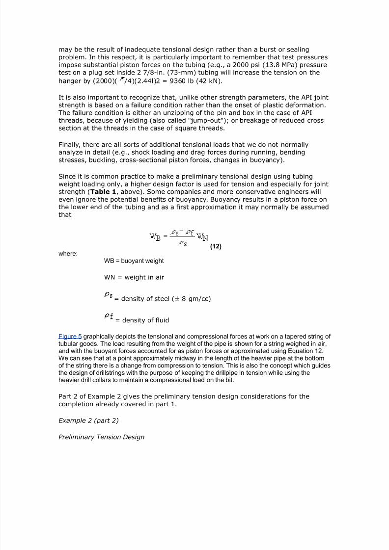
7242019 Completion Equipment
httpslidepdfcomreaderfullcompletion-equipment 1884
Figure 1
Tensionamp$ompression
In high rate roduction areas and thermal -ells e1ansion of the roduction tubingma imose additional tension on the casing strings ia the ac6er
$ouplings
In high ressure (000 siD 34 Pa) high temerature (300B ltD 4 ) andor
seerel sour conditions remium casing coulings are recommended
aterial Selection
In sour enironments material secification must consider the chances of Hcontamination of the casingtubing annulus and the added ossibilit of temerature
changes during stimulation affecting the stress corrosion tolerance of the ie
Couplings
There are man forms of couling aailable some of -hich hae been dedicated tothe ublic through the ausices of the API -hile others are roduced b or under
7242019 Completion Equipment
httpslidepdfcomreaderfullcompletion-equipment 1984
license from a secific manufacturer It -as in fact the need to obtain astandardi+ation of thread forms and diameters that led to the formation of the API
ommittee on tandardi+ation of Tubular Moods in 4
The API coulings ( ltigure
Figure 1
ltigure and ltigure 3
7242019 Completion Equipment
httpslidepdfcomreaderfullcompletion-equipment 2084
Figure 2
$utaways of basic types of couplings) are of three basic tes e1ternal uset (gtKgt)
nonuset (ampK) and integral 8oint
7242019 Completion Equipment
httpslidepdfcomreaderfullcompletion-equipment 2184
Figure 3
Threads are of t-o main forms The round API threads are -ea6er than the ie
bod (ie N00 efficient) The buttress threads -ere deeloed b the ampationalTube Giision of the Knited tates teel ororation to roide a high strength
couling for dee high ressure -ell serice This thread is used in a number ofrorietar coulings eg Hdril A Atlas2radford
All taered threads achiee a seal b driing the in and bo1 surfaces together undersufficient stress to generate a bearing ressure e1ceeding an differential that is to
be subseuentl alied Ho-eer a small siral oid is al-as left bet-een themating surfaces and must be filled -ith solids in the form of thread comound (This
is the reason for careful secification of the comound in 2ul A) Ln API roundthreads this oid occurs bet-een the crest and root of the mating threads -hile on
buttress threads it e1tends oer the -hole flan6 of the thread on the beeled side
To imroe lea6 resistance eseciall at eleated temeratures and under high
ressure differential the socalled remium seals -ere deeloed These consist of either metaltometal seals on taered ortions of the in and bo1 surfaces or an
elastomer seal ring or both This te of seal reuires a high ualit finish andrecise gauging and insection The couling is therefore more costl ince API and
7242019 Completion Equipment
httpslidepdfcomreaderfullcompletion-equipment 2284
buttress threads hae roen to be er reliable in the field the decision to use themore e1ensie remium seals reuires careful economic 8ustification In general
their alication has roen aluable in highl corrosie conditions in high ressuregas -ells or high ressurehigh ML7 oil -ells and in thermal -ells sub8ect to high
comressie loads The ma be used -here -or6oer costs are high (egoffshore) In general API tubulars are adeuate for differential ressures of less than
000 si (344 Pa) and temeratures of less than 300B lt (0B ) using hightemerature thread comound ltor corrosie conditions and continuous gas sericethe ressure limit is often reduced to 00 si ( Pa)
gt1ercises
)ilfield nits
The in 4 lbft J ampK tubing string in a 000ft oil -ell -as designed
based on the tubing5s buoant -eight in -ater =hat additional load -ould beimosed on the tubing if a rod um -ere to be ressure tested to 00 si after the
-ell had been oerating for some time and the annulus umed offQ The -ell
roduces 30B API oil (M 0) -ith no -ater
If coman olic dictates the use of a design factor of for 8oint strength can
this ressure test be safel carried outQ
SI nits
The 3mm ( in) 6gmm (4 lbft) J ampK tubing string in an 30moil -ell -as designed based on the tubing5s buoant -eight in -ater =hat additional
load is imosed on the tubing if a rod um -ere to be ressure tested to 3 Paafter the -ell had been oerating for some time and the annulus umed offQ The
-ell roduces 6gm3 oil (M 0) -ith no -ater
If coman olic dictates the use of a design factor of for 8oint strength can
this ressure test be safel carried outQ
olutions
)ilfield nits
=eight in air E 000 ft 1 4 E 3400 lb
2uoanc in -ater E E 0
(densit of -ater gmccD densit of steel E gmccD use gtuation )
12
7242019 Completion Equipment
httpslidepdfcomreaderfullcompletion-equipment 2384
Buoyant ampeight amphen run (gt x 65 ((9 lb
=ater gradient (M E ) E 0433 sift
Lil gradient (M E 0) E 0 1 0433 E 03 sift
IG of tubing E 44 in Ai E 40 in
=eight of oil in tubing E 000 1 03 1 40 E 04 lb
Total alied tensile force at the surface after -ell has been umed off euals
Ceight of oil ampeight of tubing in dry casing applied pressure x area of tubing I4 19gt2 (gt 5 gt93 19gt2 (gt 2(gt 51(2 lb
The API 8oint strength rating of in 4 lbft J nonuset tubing E 00lb
If a design factor of for 8oint strength is dictated b coman olic the
allo-able tensile loading (-ith design factor) E (00) ()E 4400 lb
Therefore the roosed loading e1ceeds the design secifications and a lea6 mightoccur during the test In fact the loading e1ceeds design secs een -ithout adding
the 00 si of -ellhead ressure (actual load 404 lb comared -ith an allo-ableof 4400 lb) Ho-eer using a 33 design factor for oerating loading conditions
ressure tests of u to 4 si -ould be ermissible
6293 1((3 19gt2 (gt pt gt93
Pt E 4 si
+ nits Ceight in air 1( x 5 16(5 kg 165 kM
2uoanc factor in -ater E E 0
(densit of -ater E gmccD densit of steel E gmccD use gtuation )
12Buoyant ampeight amphen run 165 x 65 1gt2 kM
=ater gradient (M E 0) E 4 6PamLil gradient (M E 0) 0 1 4 E 6Pam
7242019 Completion Equipment
httpslidepdfcomreaderfullcompletion-equipment 2484
IG of tubing E mm thus Ai E 30 1 l04 m
=eight of oil in tubing E (30 m) ( 6Pam) (30 1 03 m)E 44 6amp
Total alied tensile force at the surface after -ell had been umed off euals
Ceight of oil ampeight of tubing in dry casing applied pressure x area of tubing I4 gt6gt 165 (5 (1 x 1 -(3 gt6gt 165 156 22gt6 kM
8ro 8igure 1 the PI Aoint strength rating of 6(- 5 kg7 )-55 nonupset tubing is
629 lbs (222 kM3
Figure 1
If a design factor of for 8oint strength is dictated b coman olic the
allo-able tensile loading (-ith design factor)
(222715 2152 kM
7242019 Completion Equipment
httpslidepdfcomreaderfullcompletion-equipment 2584
$herefore the proposed loading exceeds the design specifications and a leak ight occur duringthe test In fact the loading exceeds design specifications een at ero ampellhead pressure actualload of gt6gt 165 216 kM copared ampith an alloampable load of 2152 kM3
Ho-eer using the 33 design factor for oerating loading conditions ressure tests
of u to 6Pa -ould be ermissible
216 pt (1 x l-gt3
t E 4 6Pa
2 )ilfield nits 12-ft hydrostatically pressured gas ampell γ g 63 is to be copleted Chat closed-in tubing
head pressure can be expectedN If the casing ampellhead and tubing are to be designed for asFueee kill at fracture propagation pressure 8PP3 amphat ampellhead pressure ampould be expected atthe start of the kill operationN Gse EFuation 1( for estiating the 8P3
13
+ units (99- hydrostatically pressured gas ampell γ g 63 is to be copleted Chat closed-in tubinghead pressure is expectedN
If the casing -ellhead and tubing are to be designed for a suee+e 6ill at fractureroagation ressure (ltPP) -hat -ellhead ressure -ould be e1ected at the start
of the 6ill oerationQ (Kse gtuation 3 for estimating the ltPM)
olutions
)ilfield nits
Condition Loading Design Criteria Typical Design Factor
Burst Internal Kill pressure on
hydrocarbon-filled tubing
1125
External Packer fluid and eroannulus pressure
onsiderations heck effects ofcopression
ollapse External asing head pressure 1125
7242019 Completion Equipment
httpslidepdfcomreaderfullcompletion-equipment 2684
shut-in tubing pressure
Internal $ubing epty anddepressured
onsiderations heck effects of tension
$ension unning Buoyant ampeight in Body 1(((
copletion fluid )oint 1+
$ension andopression
perating old stiulation and hotproduction conditions
Body 1125
)oint 1(((
onsiderations heck effects ofteperature andpressure changes
$otal tress $riaxial ax stress 0 yield
CAssuming searate chec6s are not lanned on shoc6 and bending effectsD other-iseuse
Table 1 Typical criteria for tubing design on a flowing well
The ratio of THP to 2HP for γ g of 0 E 04
At 000 ft assuming a hdrostatic gradient of 0433 sift the bottomholeressure can be estimated as
BP 12 x gt(( 519 psiampith gas surface pressure 519 x 6gt6 I$P (1 psi
Assuming the oerburden gradient to be sift and using gtuation 3 to estimate
the fracture roagation ressure
E 0 sift
ltPP E 0 000 ft E 04 si
axiu ampellhead pressure at the start of the kill operation $IP3 ampill eFual the forationpropagation pressure inus the pressure due to the gas gradient
7242019 Completion Equipment
httpslidepdfcomreaderfullcompletion-equipment 2784
$IP 12 6163 - 519 - (13 62 psigore correctly ampe should use the ratio in Table 1 since the increased pressure ampill increase thegas density
$IP 12 6163 6gt6 9gt26 psi$herefore a 5 psi ampellhead should not be used een though the axiu closed-in tubinghead pressure is only about gt psi
SI nits
7eferring to Table 1
The ratio of THP to 2HP for γ g E 0 E 04
At 30 m assuming a normal hdrostatic ressure of 6Pa m bottomholeressure can be estimated as
BP (99 65 (55 kPa
ampith gas surface pressure (55 6gt6 I$P 296 kPa
Assuming the oerburden gradient to be 6Pam and using gtuation 3 toestimate the fracture roagation ressure
E 6Pam
ltPP E 30 E 3 6Pa
axiu ampellhead pressure at the start of the kill operation $IP3 ampill eFual the foration propagation pressure inus the pressure due tothe gas gradient
THIP E (30 ) (30 0) E 0 6Pa
ore correctly ampe should use the ratio in Table 1 since the increased pressure ampill increase thegas density
$IP (99 19213 6gt6 gtgt(1 kPa
9gt Pa ampellhead should therefore be used
3hellip)ilfield nits
A 000ft -ell that is to be roduced -ith a target of 000 T2d using intubing encounters 0 ft of oilbearing formation -ith a ressure of 3000 si =hat
rating of -ellhead should be usedQ If a single grade and -eight of tubing is to be
7242019 Completion Equipment
httpslidepdfcomreaderfullcompletion-equipment 2884
used -hat is the cheaest string that can robabl be run assuming that
Grade -eight lbft
Collapse
+trength psi
urst
+trength psi
Tensional
+trength 1 lb
Cost Coparison
)-55 155 gtgt gt1 ( cheapest
16 gt1 5(2 (2
-65 16 96 625 gt2( ost expensie
M- 16 92 66gt gtgt9 oderately expensie
2 ( 52gt
ac6er fluid inhibited sea-ater (gradient E 043 sift)
reseroir ressure 3000 si
6ill ressure 000 si aboe I2HP (suee+ing gas)N fracture roagation ressure (suee+ing oil)
ltracture roagation ressure gradient (ltPM) is aro1imatel
8P 5 5 psi7ft3
If gas cap gas should break through into the ampell assue gas graity 95
Kse Table 1 to calculate head of gas
Condition Loading Design Criteria Typical Design Factor
Burst Internal Kill pressure onhydrocarbon- filledtubing
1125
External Packer fluid and ero
annulus pressure
onsiderations heck effects ofcopression
ollapse External asing head pressureshut-in tubing pressure
1125
Internal $ubing epty and
7242019 Completion Equipment
httpslidepdfcomreaderfullcompletion-equipment 2984
depressured
onsiderations heck effects of tension
$ension unning Buoyant ampeight incopletion fluid
Body 1((( )oint 1+
$ension andopression
perating old stiulation and hotproduction conditions
Body 1125)oint 1(((
onsiderations heck effects ofteperature andpressure changes
$otal tress $riaxial ax stress 0 yield
CAssuming searate chec6s are not lanned on shoc6 and bending effectsD other-iseuse
Table 1 Typical criteria for tubing design on a flowing well
Assume lie oil gradient is 03 sift
onsider onl the ma1imum burst at the -ellhead the ma1imum collase load at theac6er and the running tension
SI nits
A 30m -ell that is to be roduced -ith a target of 400 m3da of oil -ith l40mm ( inch) tubing encounters 0 m of oilbearing formation -ith a ressure of
000 6Pa =hat rating of -ellhead should be usedQ If a single grade and -eight oftubing is to be used -hat is the cheaest string that can robabl be run assuming
that
Grade -eight
$gmm
Collapse
+trength
$Pa
urst
+trength
$Pa
Tensional
+trength
$amp
Cost Coparison
)-55 2(1 2655 ((19gt 1((gt cheapest
25( ((5( (99 1gt9(
-65 25( gt151 gt6 12 ost expensie
M- 25( gt(2 5((95 1gt oderately expensie
2 9 91gt 2((1
7242019 Completion Equipment
httpslidepdfcomreaderfullcompletion-equipment 3084
ac6er fluid inhibited sea-ater (gradient E 40 6Pam)
reseroir ressure 000 6Pa
6ill ressure 000 6Pa aboe I2HP (suee+ing gas)N fracture roagation ressure (suee+ing oil)
ltracture roagation ressure gradient (ltPM) is aro1imatel
8P 53 22(3 5 kPa7If gas cap gas should break through into the ampell assue gas graity 95
Kse Table 1 to calculate head of gas
Assume lie oil gradient is 6Pam
onsider onl the ma1imum burst at the -ellhead the ma1imum collase load at the
ac6er and the running tensions
olution
)ilfield nits
I$P IBP - o 4
o ( psi7ft
under operating conditions I$P ( - ( 63 psi
under axiu conditions assuing gas breakthrough3
ITHP E 04 1 2HP (from Table 1)
AR ITHP E 04 1 3000 E si
under 6ill conditions
8P 5 5
5 5 x 61 psi7ft
ltPP E 000 0
E 000 si
7242019 Completion Equipment
httpslidepdfcomreaderfullcompletion-equipment 3184
O BIP oil kill3
5 psieFuialent $P oil kill3
5 - ( x 6 2 psi
In the case of a gas kill
Iamp 2HIP(gas 6ill)
( 1 psi gt psi
eFuialent $P gas kill3
5gt x BP 5gt x gt (gt19 psi
8ro this ampe see that amphile ampe could probably get aampay ampith a ( psi ampellhead strictlyspeaking ampe should be using a 5 psi ampellhead
Incororation of the roision in some regulations for a -ellhead rating euialent
to the reseroir ressure reflects this tical design for 6ill caabilit
Tubing urst (ating
burst rating E ma1 THP design factor
design factor E
reuired burst rating (for gas 6ill conditions) E 34 E 343 si
All grades and -eights satisfactor
Tubing Collapse )oading Calculation
alculate first assuming a high ris6 of gas brea6through
head of packer fluid f 3 43 gt(53 63 (gt5 psi
ma1 HP E ma1 ITHP (assumes lea6)E si
ma1 2H annulus ressure E F 304E 0 si
7242019 Completion Equipment
httpslidepdfcomreaderfullcompletion-equipment 3284
ma1 collase load E 0 0 si (assumes emt tubing)E 0 si
design factor E
reuired collase rating E 0 1 si
E 30 si
$herefore strictly speaking ampe should use 2-lb7ft M- tubing although it is ore likely a l6-lb7ft ampould be selected since the probability is ery loamp that such seere collapse-loadingassuptions ampould proe true
alculate ne1t assuming a lo- ris6 of gas brea6through
ax P operating I$P
oerating ITHP E 00 si
ma1 2H annulus ressure E 00 F 304 siE 34 si
ma1 collase load E 34 si
reuired collase rating E 34 E 443 si
Ce could select 16 lb7ft )-55 tubing
(unning Tension Calculations
ampeight in air C 4 16 lb7ft3 6 ft3 11 lb
buoyancy factor
625
buoant -eight of tubing E 0 000 lb
E 04000 lb
design factor E
reuired tension rating E (04000) () lb
16 lb$his can be easily carried by any of the tubing grades listed
7242019 Completion Equipment
httpslidepdfcomreaderfullcompletion-equipment 3384
It is tical for collase design to be the critical factor in highrate largetubingcomletions eseciall at relatiel shallo- deths
Conclusion
in 0lbft amp0 tubing meets all criteria for this te of roduction 7is6 of
gas brea6through must be accuratel assessed before choosing bet-een amp0 and J grades
SI nits
I$P IBP - ρo x 4
ρo 969 kPa7
under operating conditions I$P 26 - 969 x 21(3
92gt9 kPaunder axiu conditions gas breakthrough3
ITHP E 04 1 2HP (from Table 1)
AR ITHP E 04 1 000 E 6Pa
under 6ill conditions
8P 53 22(3 5
53 22(3 5
19 kPa7
ltPP E (30) (00)
E 3400 6Pa
O BIP oil kill3 (gt kPa eFuialent $P oil kill3 (gt - 969 x 21(3
1929 kPa
In the case of a gas 6ill
Iamp 2HIP
(gas 6ill) E 000 F 000 6Pa
266 kPaeFuialent $P gas kill3 5gt x BP
5gt x 266 2(959 kPa
8ro this ampe see that amphile ampe could probably get aampay ampith a 26 Pa ampellhead strictlyspeaking ampe should be using a (gt5 Pa ampellhead
7242019 Completion Equipment
httpslidepdfcomreaderfullcompletion-equipment 3484
Incororation of the roision in some regulations for a -ellhead rating euialentto the reseroir ressure reflects this tical design for 6ill caabilit
Tubing urst (ating Calculation
burst rating E ma1 THP 1 design factor
design factor E
reuired burst rating (for gas 6ill conditions) E 3 1
E 3 6Pa
All grades and -eights satisfactor
Tubing Collapse )oading
alculate first assuming high ris6 of gas brea6through
head of packer fluid ρf 3 43
gt3 21(3 25 kPa
ax P ax I$P assues leak3 1696 kPa
ma1 2H annulus ressure E F 0
E 33 6Pa
ma1 collase load E 33 0 6Pa (assumes emt tubing)
E 33 6Pa
design factor E
reuired collase rating E 33 1 E 434 6Pa
Therefore strictl sea6ing -e should use a 6gm amp0 tubing but moreli6el 36gm tubing -ould be selected since the robabilit of such seere
collase loading is er lo-
alculate ne1t assuming lo- ris6 of gas brea6through
ax P operating I$P
oerating ITHP E 4 6Pa
ma1 2H annulus ressure E 4 F 0
E 0 6Pa
ma1 collase load E 0 6Pa
7242019 Completion Equipment
httpslidepdfcomreaderfullcompletion-equipment 3584
reuired collase rating E 0 1 E 300 6Pa
Ce could select 25(-kg7 )-55 tubing
(unning Tension Calculation
ampeight in air 25( 21( 5( kg 525 kM
buoanc factor E
EE0
buoant -eight of tubing E 0 6ampE 4 6amp
design factor E
reuired tension rating E (4) ()
E 30 6amp
$his can be easily carried by any of the tubing grades listed
It is tical for collase design to be the critical factor in highrate largetubing
comletions eseciall at relatiel shallo- deths
Conclusion
40mm ( inch) 36gm 0 tubing meets all criteria for this te ofroduction 7is6 of gas brea6through must be accuratel assessed before choosing
bet-een 0 and J grades
Pac6ers
Pac$er unctions
A ac6er is a subsurface tool that roides a seal bet-een the tubing and
casingthereb reenting the ertical moement of fluids across this sealing oint
Pac6ers are used for the follo-ing reasons
9 to imroe safet b roiding a barrier to flo- through the annulus
7242019 Completion Equipment
httpslidepdfcomreaderfullcompletion-equipment 3684
9 to 6ee -ell fluids and ressures isolated from the casing
9 to imroe flo- conditions and reent heading
9 to searate +ones in the same -ellbore
9 to lace 6ill fluids or treating fluids in the casing annulus
9 to ac6 off erforations rather than use suee+e cementing
9 to 6ee gas lift or hdraulic o-er fluid in8ection ressure isolated from the
formation
9 to anchor the tubing
9 to install a casing um
9 to minimi+e heat losses b allo-ing the use of an emt annulus or thermal
insulator
9 to isolate a casing lea6 or lea6ing liner la
9 to facilitate temorar -ell serice oerations (eg stimulations suee+es)
Pac$er T+pes
There are man ac6er manufacturers some of -hom offer an e1tensie ariet ofac6ers -ith each differing to some degree from those of the other manufacturers
This rather be-ildering arra can ho-eer be groued into rincial classes or
tes and ma be further categori+ed b method of setting b direction of ressureacross the ac6er and b the number of bores through the ac6er
Pac6ers can be rimaril classified as either retrieable or ermanent or
ermanentretrieable or inflatable
)etrievable acers
This te of ac6er is run on the tubing ( ltigure )etrievable pacer )
7242019 Completion Equipment
httpslidepdfcomreaderfullcompletion-equipment 3784
Figure 1
After setting it can be released and recoered from the -ell on the tubing ince it is
an integral art of the tubing string the tubing cannot be remoed from the -ell-ithout ulling the ac6er unless a detachable ac6er head is used
7etrieable ac6ers ma be designed to be set mechanicall or hdraulicallechanical setting methods include rotation of the tubing string recirocation of the
tubing string or the alication of tension or setdo-n -eight =ith mechanical
ac6ers the tubing is usuall set in comression
Hdraulic ac6ers are set b aling hdraulic ressure through the tubing stringbut once set the hold the set osition mechanicall The tubing is usuall in tension
7etrieable ac6ers are usuall used for comle1 multi+one and multistringcomletions Their main limitation -as in their limited abilit to accommodate tubing
stress changes -ithout unsettingD the aailabilit of effectie sli 8oints anddetachable heads has eased this situation An historical roblem -as failure of the
internal elastomer seals but this technolog also has imroed mar6edl in the lastdecade All metaltometal seal ac6ers are aailable but are e1ensie
7242019 Completion Equipment
httpslidepdfcomreaderfullcompletion-equipment 3884
Lne disadantage of retrieable ac6ers is that if the fail to retriee the must beremoed b milling them out of the casing -ith an abrasie milling head and a
drillstring The are er difficult to mill Menerall this te of ac6er is used undernonseere conditions (differential ressures less than 000 si (344 Pa)
temeratures less than 300B lt (4B )
2ecause of the setting mechanism retrieable ac6ers tend to hae a restrictedbore comared -ith other ac6ers designed for the same casing si+e This factorma restrict flo- or limit -ireline oerations belo- the ac6er deth
ermanent acers
Permanent ac6ers are indeendent of the tubing and ma be run on tubing or on
-ireline ( ltigure and ltigure 3 )
Figure 2
The tubing can be released from the ac6er and can be ulled leaing the ac6er set
in the casing
7242019 Completion Equipment
httpslidepdfcomreaderfullcompletion-equipment 3984
Figure 3
Tubing can subseuentl be run bac6 and resealed in the ac6er The ac6er ma
thus be considered an integral art of the casing It is sometimes called either aroduction ac6er or a retainerroduction ac6er
The ermanent ac6er cannot be recoered as such but it can be destructiel
remoed (eg b milling) ( ltigure 4 and ltigure )
7242019 Completion Equipment
httpslidepdfcomreaderfullcompletion-equipment 4084
Figure 4
If the ac6er includes a tailie and must be recoered a millout e1tension is
needed on the ac6er for the ac6er ic6er or catch sleee on the mill to engageIn other cases it ma be adeuate to siml ush the ac6er to the bottom of the
casing after milling
7242019 Completion Equipment
httpslidepdfcomreaderfullcompletion-equipment 4184
Figure amp
Permanent ac6ers can be set using an electric -ireline setting tool a hdraulicsetting tool run on drillie or tubing or b a combination of rotation and ull
Permanent ac6ers are ticall used -hen
9 formation treating or s-abbing differential ressures -ill be high
9 it is desirable to ull the tubing -ithout unseating the ac6er
9 it might be desirable to conert the ac6er to a temorar or ermanentbridge lug
9 high bottomhole temeratures e1ist
9 tubing oerating stress ariations -ould not be accommodated -ith a
retrieable ac6er -ithout ma6ing it imossible to ull
9 a retrieable ac6er -ould hae an inadeuate bore
ermanent+)etrievable acers
7242019 Completion Equipment
httpslidepdfcomreaderfullcompletion-equipment 4284
A recent arrial this te of ac6er has the same characteristics as the ermanentac6er but it can -hen desired be released -ith a secial ulling tool and
recoered
nflatable acers
These are ac6ers -ith a fle1ible sealing element that can be e1anded hdraulicallusing either comletion fluid or cement The are used as oenhole ac6ers or -hen
the casing is buc6led or collased reenting the usage of conentional ac6ers
Inflatable ac6ers cannot stand high ressure differentials and are generall limited
to secial alications such as drillstem testing
acer -ailures
The ma8or causes of socalled ac6er failures relate to
9 use of the ac6er outside its oerating range
9 unsetting of the ac6er or seal assembl as a result of ressure ortemerature changes
9 using or setting the ac6er incorrectl
9 the ac6er being in oor condition -hen run
Gifficult oerating conditions reuire more e1ensie euiment and more rigorous
design -or6 It is imortant to remember that a ac6er is effectiel a iston -ithin
the casing and -ill therefore be heail affected b changes in differential ressurePressure from belo- or increasing string tension due to tubing contraction or both
tend to unset the follo-ing
9 -eightset ac6ers
9 hdraulicall set ac6ers not euied -ith holddo-n buttons
9 locator seal assemblies or oershots
Pressure from aboe tends to unset tensionset ac6ers or cause collasete
failures or lea6age at seal assemblies under high ressure differentials
Tubing0acer Forces and oveent
hanges in temerature and ressure inside and outside the tubing affect the lengthof the tubing string (if the string is designed to ermit motion) and the forces
e1erted at the ac6er (if no motion is ermitted)
These changes in tubing length or force bet-een roducing and umin conditions
can be large and should be considered in choosing a ac6er This is eseciallimortant in high temerature (usuall dee) -ells and ma limit the use of
7242019 Completion Equipment
httpslidepdfcomreaderfullcompletion-equipment 4384
retrieable ac6ers Gesign of sli 8oints and seal assemblies must also considerthese forces
(The follo-ing section dra-s heail on the -or6 of GJ Hammerlindl () and
Arco as ublished in T ltebruar and on that of Arthur $ubins6i = Althouse and T $ $ogan ())
actors Causing Pac$er orces or Tubing o-ement
If the tubing string is free to moe its length -ill change as a result of temeratureand ressure influences -hich ma be subdiided into thermal iston force
ballooning and buc6ling effects onsideration of these effects -ill determine theseal length reuired andor sli 8oint design
If the tubing is anchored to the ac6er these effects -ill result in a change In thea1ial tension in the tubing This can affect not onl the design of the uermost
tubing 8oint but also ac6er shear in rating and the degree of buc6ling aboe theac6er and therefore the throughbore access A mechanical force is also inoled in
this situation
To consider these effects it is necessar to define the critical conditions to be
e1amined These normall include
bull landing conditions=
bull oerating conditionsD
bull shutin conditionsD
bull 6illingstimulating conditionsD
bull ressure test conditions
Initial calculations are ade for a set of assued landing conditions eg -5 to 5 lb -225 to 225 kM3 tension -3 or copression 3 8or conenience adesigner ay soeties choose to exaine only the differences betampeen amphat are considered tobe the ost seere conditions ie hot producing to cold stiulating3= hoampeer these are notalampays apparent eg pressure test loads can be the ost seere3
ecanical orces
echanical forces can be subdiided into tension and comression Tension results in
the stretching of tubing string The elongation due to tension forces can bedetermined b Hoo6e5s la- -hich states that the change in length is directl
roortional to the alied force The euation for Hoo6e5s la- in this alication isas follo-s
1amphere
7242019 Completion Equipment
httpslidepdfcomreaderfullcompletion-equipment 4484
length change inches3 lt tubing length inches3 8t tensional force -3 lbf3 E HoungQs odulus ( 19 psi3
s cross-sectional area of the tubing ampall in23$his relationship is the basis of the tubing stretch tables and graphs published by arious
eFuipent anufacturers
Temperature or Termal Effects
The length change due to change in temerature is eual to the length of the tubing
times the coefficient of thermal e1ansion for steel times the change in aeragetemerature
ince
1then
1(amphere
change in tensional force in tubing at the surface due to teperaturechange
s the coefficient of theral expansion for steel β3 is 9 l-97L8 12gt2 l-97L3 and HoungQsodulus E3 is ( x 19 psi 26 Pa3
-26 s ∆$ lb7L8
ltt E As ∆T ampB
In ost cases it is adeFuate to deal ampith the change in the aerage string teperature It is oftenassued that
bull the copletion is at geotheral gradient amphen landed 1 to 2L 871 ft or 1 to (9L71 3
bull during stimulation6illing it -ill stabili+e -ithin 0B lt (0B ) of ambient
temerature
$he teperature during producing conditions is a function of floamp rate gas expansiongeotheral gradient theral insulation of the tubing and the like Rarious coputer prograsare aailable to calculate this in critical cases but it is usually adeFuate to use data fro offsets
producing under siilar conditions Production test data should be used Audiciously since testrates and floamp periods are often too loamp and too short for theral stabiliation to occur s a firstapproxiation designers ampill often assue a floamping gradient for high rate ampells of gt L871 ftor 6 L71
Piston orce Effects
The most familiar form of iston force is that of the stretch andor stress induced
-hen ma6ing an internal ressure test against a lug set inside a string of tubing
7242019 Completion Equipment
httpslidepdfcomreaderfullcompletion-equipment 4584
The force against the lug is eual to the ressure alied times the crosssectionalarea of the tubing IG
8p pt i 18or exaple a 1 psi 9 kPa3 pressure test on ( 172-in 3 tubing I4 22 in3should result in a force of
8p 1 2232 6 lb (11 M3
Chere the tubing is inserted into a packer ampe ust siilarly consider the piston effects on thecross section of the steel as it is affected by changes in the internal and external pressure
The iston force at the ac6er related to a change in the inside and outside ressures
is
8p p - i3 pi - p - o3 po 2amphere
p area of packer bore
Ai E area of tubing IG
Ao E area of tubing LG
$he change in tubing length related to this piston force is
21
amphere the pi and ∆po changes are considered positie if they correspond to an increase andnegatie if they correspond to a decrease in pressure 8igure 1 Schematic showing piston force
at the packer related to a change in the inside and outside pressures3
7242019 Completion Equipment
httpslidepdfcomreaderfullcompletion-equipment 4684
Figure 1
The iston forces are in essence the change in the buoant force on the tubing
allooning Effects
As the ressure inside the tubing increases the ie e1ands radiall This -ill cause
an a1ial shortening Alication of ressure to the annulus -ill cause the tubingdiameter to contract (reerse ballooning) This -ill result in a tubing elongation
The length change accounts for the change in radial ressure forces due to surface
ressure changes (∆is and ∆os) and fluid densit changes (∆ρi and ∆ρo) as -ell as
flo- inside the tubing (δ ) The formula for calculating the change in length due to
ballooning is
7242019 Completion Equipment
httpslidepdfcomreaderfullcompletion-equipment 4784
22amphere
PoissonQs ratio of the aterial for steel (3
7 E ratio LGIG of the tubing
δ E dro in ressure in the tubing er unit length due to flo- The
ressure dro is ositie -hen the flo- is do-n-ard and +ero -henthere is no flo-
ρi E densit of fluid inside tubing
ρo E densit of fluid outside tubing
is E surface tubing ressure
os E surface annulus ressure
ucling ffects
2uc6ling is caused b t-o effects alied longitudinal comression loads andinternal ressure
The first is eas to understand as a logical conseuence of the loading of a columnHo-eer the buc6ling of a ie under tension as a result of internal ressure is a
difficult concet to areciate Lne -a to isuali+e this te of buc6ling is toconsider a slightl bananashaed tubing 8oint sub8ect to internal ressure ( ltigure
and ltigure 3 $auses of bucling)
Figure 2
7242019 Completion Equipment
httpslidepdfcomreaderfullcompletion-equipment 4884
There -ill be a small unoosed area uon -hich the ressure -ill act to cause
distortion of the ie
Figure 3
The resulting buc6ling -ill reflect the balance of strain and bending energ This issimilar to haing a fictitious force (ltf ) acting on the end of the ie
To better understand buc6ling resulting from comression loading consider a stringof tubing freel susended inside the casing ampo- consider an u-ard force lt
alied to the lo-er end of the tubing This force comresses the string and buc6lesthe lo-er ortion of the string into a heli1 The neutral oint is -here the buc6ling
stos This force decreases -ith increasing distance from the bottom of the string
and becomes +ero at the neutral oint The distance n from the bottom of thetubing to the neutral oint is calculated from the follo-ing formula
23amphere
C Cs ρi i - ρo o representing the buoyed ampeight of the tubing per unit length 8 the force applied to the loamper end
It should be understood that in the presence of fluids the neutral point is not the point at amphichthere is neither tension nor copression but it is the point beloamp amphich the string is buckled andaboe amphich the string is straight
7242019 Completion Equipment
httpslidepdfcomreaderfullcompletion-equipment 4984
If the neutral oint is -ithin the string then the shortening of the string due to
buc6ling (∆$b) is as follo-s
24amphere I is the oent of inertia of tubing cross section ampith respect to its diaeter
I E (G4 d4)
=hen the calculated alue of the neutral oint is aboe the uer end of the string
the entire string buc6les into a heli1
=hen the ressure inside the tubing (P i) is greater than the ressure outside (o) at
the ac6er a shortening -ill occur due to helical buc6ling It -as determined b
$ubins6i Althouse and $ogan () that as far as the buc6ling is concerned thetubing behaes as if sub8ect to the follo-ing fictitious force
8f ppi - po3 2ampBecause part of this force 8f appears to be nonexistent the entire force 8 ampas gien the naefictitious 8urther it ampas deterined that the string ampould buckle if 8f is positie and ampould reainstraight if 8f is ero or negatie ubstitution into EFuation 2gt gies
2
amphere ∆ltb is the change in length ampith respect to the length of the tubing amphen landed ampith p i po
If the ressure outside the tubing is greater than the ressure inside the tubing atthe ac6er (o i) there is no helical buc6ling due to ressure
The total change in tubing length as a result of these arious factors (mechanical andiston forces and thermal ballooning and buc6ling effects) ma be e1ressed as
lt lt ltt ltp ltB ltb 2
$he effect of this net change in tubing length on the tubing stress ampill depend upon the aount ofotion peritted by the packer design
Permanent Cor$screing
If the buc6ling results in the ield strength of the tubing being e1ceeded ermanentcor6scre-ing can occur In addition to the stresses of helical buc6ling the tubing issub8ect to elongational stresses as -ell as tangential and radial stresses due to
ressure inside and outside the tubing A tria1ial stress analsis must be made -hereconditions suggest that significant tubing stress -ill result All the ma8or euiment
suliers hae comuter and hand calculator rograms aailable for ma6ing thesecomutations This serice is usuall aailable free to urchasers The roduction
engineer should send some time determining the ressure and temeratureconditions to be e1ected Ticall a series of calculations is made for arious
7242019 Completion Equipment
httpslidepdfcomreaderfullcompletion-equipment 5084
landing assumtions and the results lotted for analsis It is also useful to ma6e atleast one hand calculation as a crosschec6 on the data receied
gt1ercise
1 )ilfield nits
A 0000ft highrate oil -ell is comleted -ith in lbft tubing (-allthic6ness 0 in) Knder roducing conditions the flo-ing temerature gradient is
04 Bltl00 ft and under static conditions the geothermal gradient is Blt00 ftfrom a mean surface temerature of 40 Blt =hen the -ell is 6illed -ith a large
olume of 40 Blt sea-ater the bottomhole temerature dros to 0 Blt If free tomoe -hat tubing moement can be e1ected from the landing condition to the hot
roducing and to the cold in8ection conditionsQ If a hdraulic ac6er -ere to be usedand set in 30000 lb of tension -hat -ould be the tension loading on the ac6er
after 6illing the -ellQ (Kse gtuation and ignore iston ballooning and buc6lingeffects)
1(
+ nits
A 300m highrate oil -ell is comleted -ith 40mm 36gmm tubing (-allthic6ness E mm) Knder roducing conditions the flo-ing temerature gradient is
03 B00 m and under static conditions the geothermal gradient is 3 Bl00 mfor a mean surface temerature of 0 B =hen the -ell is 6illed -ith a large
olume of 0 B sea-ater the bottomhole temerature dros to 0 B If free tomoe -hat tubing moement can be e1ected from the loading condition to the hot
roducing and to the cold in8ection conditionsQ If a hdraulic ac6er -ere to be usedand set in 334 6amp tension -hat -ould the tension loading on the ac6er be after
6illing the -ellQ
(Kse gtuation and ignore iston ballooning and buc6ling effects)
olution
)ilfield nits
7eseroir temerature E 40 F ( 1 0000 S 00) E 0 Blt
Temerature loss u the tubing E 04 1 0000 S 00 E 40 Blt
ltlo-ing tubing head temerature E 0 40 E 0olt
ltrom landing conditions to roducing conditions
7242019 Completion Equipment
httpslidepdfcomreaderfullcompletion-equipment 5184
ltt lt3 β 3 $3
13 9 1-93 $3
amphere $
$anding E 30Blt
Producing E 00Blt
$ 2 - 1( 6L8
$t E (0000) ( 1 0) (0) E F43 ft
amphere 1 initial aerage teperature in tubing string
2 final aerage teperature in tubing string $surf surface tubing string teperature $B bottohole tubing string teperature
8ro producing to inAection conditions
Producing E 00 Blt
In8ection E Blt
$ 55 - 2 -1gt5L8
ltt lt3 β 3 $3 13 9 1-93 -1gt53 -1 ft
$herefore the axiu oerall length change is -1 ft fro producing to inAection
gtuation states the change in tension to be
8t -Eβ 3 s3 $3for tubing ampith 4 55 in and I4 gt5 in
gt51 in2
Betampeen landing and inAecting conditions the apparent force acting on the tubing to cause thecontraction effect is
7242019 Completion Equipment
httpslidepdfcomreaderfullcompletion-equipment 5284
8t -E3 β 3 s3 $3 -( x 193 9 1-93 gt513 55 - 1(3 616 lb force
$o aintain the original tubing length the packer ust exert an eFual and opposite force
8p -616 lb f tension3If the tubing ampas landed in ( lb tension the net tension at the packer leel is
8p -616 - (
lt E 000 lb force (tension)
$his is ampell in excess of feasible shear pin arrangeents and therefore a hydraulic packer cannotbe used $his ampell should be copleted ampith a peranent packer and a locator seal assebly ofseal receptacle peritting 1 ft of trael
SI nits
7eseroir temerature E F E 00 B
Temerature loss u the tubing (flo-ing) E
6( 22( L8loamping tubing head teperature 15 - 22( 26L
ltrom loading conditions to roducing conditions
ltt lt3 β 3 $3
(53 12gt2 l-93 $3
amphere $ 2 - 1
$anding E B
Producing E 3B
$ 2 - 1 ( - 55 (L
$t E (300) (4 1 0) (3) E 4 m
amphere
1 initial aerage teperature in tubing string
2 final aerage teperature in tubing string $surf surface tubing string teperature $B bottohole tubing string teperature
7242019 Completion Equipment
httpslidepdfcomreaderfullcompletion-equipment 5384
8ro producing to cold inAection conditions
Producing E 3B
In8ection E 30B
$ 2 - 1 1( - ( -L
ltt lt3 β 3 $3 (53 12gt2 1-93 -3 -(9
$herefore the axiu oerall length change is (9 fro production to inAection
gtuation states the change in tension to be
8t -Eβ 3 s3 $3for tubing ampith 4 1gt and I4 129
s 1gt2 - 12923 2 225 1-( 2
Betampeen landing and inAection conditions the apparent force acting on the tubing to cause thecontraction effects is
8t -E3 β 3 s3 $3 -29 193 12gt2 1-93 225 1-(3 1( - 553
8t (155( kM$o aintain the original tubing length the packer ust exert an eFual and opposite force
8p -(155( kM
If the tubing ampas landed in 1((gt5 kM tension the net load at the packer is 8p -(155( - 1((gt5
-gtgt kM tensile force$his is ampell in excess of feasible shear pin arrangeents and therefore a hydraulic set packercannot be used
This -ell should be comleted -ith a ermanent ac6er and a locator seal assembl
or seal recetacle ermitting 3 m of trael
Artificial $ift gtuiment
Ancors
Knanchored tubing in a rodumed -ell -ill be sub8ect to constant moement Thetubing -ill buc6le on the ustro6e and stretch on the do-nstro6e This is sometimes
called breathing This moement leads to -ear and fatigue roblems and can resultin inefficient use of the aailable uming unit stro6e Tubing anchors are used to
minimi+e this moement
Tubing anchors are classified as follo-s
7242019 Completion Equipment
httpslidepdfcomreaderfullcompletion-equipment 5484
9 tension anchors -hich ermit the tubing to elongate but not to shorten
9 comression anchors -hich ermit shortening but not elongation
9 fi1ed anchors
$ompression anchors reduce the breathing roblems but do not reent buc6ling and
are therefore rarel used Tension anchors -hich graduall -al6 do-n the inside of the casing as the um starts to oerate and then set the tubing at its ma1imum
elongation ma damage the casing b reeated slight moement Therefore mostanchors used toda are of the fixed te (often miscalled tension anchors) ( ltigure
Figure 1
echanically set anchor ltigure
7242019 Completion Equipment
httpslidepdfcomreaderfullcompletion-equipment 5584
Figure 2
Dual hydraulically set anchor and ltigure 3 Single hydraulically set anchor )
7242019 Completion Equipment
httpslidepdfcomreaderfullcompletion-equipment 5684
Figure 3
There are t-o main setting mechanisms
9 rotation set
9 hdraulic set
It is best to select an anchor -ith a bac6u retrieing mechanism so that if therimar one (ie rotation) fails a secondar release (ie shear ins) can be used
ome hdraulic anchors deend onl uon the differential ressure bet-een thetubing and casing These hae an additional alication in reenting seal assemblies
or ac6ers from becoming unlatched during stimulation oerations
ottohole 0ups
Getails of the bottomhole um for rodumed -ells are set out in API ec AR
-hich includes a character code to secif each um te The most critical isthe second grou -hich is the um bore ( to corresonding to 4 in to
34 in or 3 to 0 mm) and the um te (7rod and Ttubing)
7242019 Completion Equipment
httpslidepdfcomreaderfullcompletion-equipment 5784
The um dislacement in oil field units can be obtained from
P4 Ep 1199 Es M 42 2(amphere
stroke in3= say 6gt in Ep pup efficiency= assue 0
M pup rate= say 2 P Es stroke efficiency or rod stretch3= assue 0 4 pup bore= say 2 in M 15 in7inute axiu desirable for rod fall3
Gsing the nubers gien aboe the pup rate ampould be P4 gt6 B7d 6 (7d3
Go-nhole omletion Accessories
Seating ampipples
There are three main tes of seating nile used as integral arts of the tubing
string
9 umseating niles
9 selectie landing niles
9 nonselectie or nogo landing niles
eating niles -hich are used to accommodate a um lug hanger or flo-
control deice consist of a olished bore -ith an internal diameter 8ust less than thetubing drift diameter Ksuall a loc6 rofile is also reuired eseciall for landing
niles Hea dut tubing sections called flo- coulings are often run on eitherend of a seating nile to minimi+e the effects of turbulence ( ltigure anding
nipple and flow coupling installation)
7242019 Completion Equipment
httpslidepdfcomreaderfullcompletion-equipment 5884
Figure 1
eating niles and the deices that are set inside them are used for the follo-inguroses
9 to facilitate ressure testing of the bottomhole assembl and tubing
coulings and the setting of hdraulic ac6ers
9 to land and seal off a bottomhole um (um seating nile)
9 to isolate the tubing if it is to be run dr for high dra-do-n erforating
9 to land -ireline retrieable flo- controls such as lugs tubing safet ales
bottomhole cho6es and regulators
9 to lug the -ell if the tree must be remoed
9 to land bottomhole ressure bombs
9 to ac6off across blast 8oints
9 to install a standing ale for intermittent gas lift
7242019 Completion Equipment
httpslidepdfcomreaderfullcompletion-equipment 5984
9 to lug the tailie belo- ac6er in order to ull the tubing -ithout 6illingthe -ell
9 to temoraril lug the -ell -hile the rig is moed on or off the -ell
Selective anding ipples
electie landing niles are niles -ith a common internal diameter In some the
loc6 rofile is aried for eas identification ( ltigure
Figure 2
ltigure 3
7242019 Completion Equipment
httpslidepdfcomreaderfullcompletion-equipment 6084
Figure 3
ltigure 4 and ltigure anding nipples and locing mandrels)
7242019 Completion Equipment
httpslidepdfcomreaderfullcompletion-equipment 6184
Figure 4
Lthers are accessed b triing the loc6 mechanism at the selected deth
7242019 Completion Equipment
httpslidepdfcomreaderfullcompletion-equipment 6284
Figure amp
electie niles are used -hen more than one nile is reuired -ithin a single
string of tubing and the designer -ishes to maintain ma1imum throughbore Theshould be no closer than 30 ft (0 m) from a similar rofile and at least 0 ft (3 m)
from an change in diameter
o+Go anding ipples
ampogo landing niles are designed -ith an IG that is slightl restricted to roide aositie shoulder to locate a loc6ing mandrel The IG of these niles should be
chec6ed against the dimensions of an throughtubing euiment that ma be usedThis te of nile is usuall located at the bottom of the tubing string or tailie and
at least ft belo- an rofile change
In tailie installations it is best to include a sliding sleee aboe the nile in case
debris reents the ulling of an lug set in the nile b regular -ireline methodsAlternatiel a mechanical erforator ma be used to unch a hole aboe the lug
Sliding Slee-es
7242019 Completion Equipment
httpslidepdfcomreaderfullcompletion-equipment 6384
Also referred to as sliding side doors or circulating sleees these tubing comonentsare used to obtain access from the tubing to the tubingcasing annulus either for
fluid circulation or to ermit a reiousl isolated +one to be roduced ( ltigure Sliding sleeves) The are oened and closed -ith a -ireline tool that has a locating
6e that engages the rofile in the sleee A Tlt$ ersion is also aailable for subseacomletions
Figure 1
These deices are ticall laced aboe each ac6er in the -ell Lbiousl the are
an essential reuirement of multi+one comletions scheduled for selectieroduction an roducers run sliding sleees in each string in a multistring
comletion to increase roduction fle1ibilit
A sleee aboe the uer ac6er is articularl useful for the follo-ing oerations
9 6ic6off b dislacing the tubing contents -ith a lo- densit fluid therebaoiding the use of coiled tubing -ithin the tubing
9 -ell 6illing rior to a tubing ulling 8ob or -or6oer
7242019 Completion Equipment
httpslidepdfcomreaderfullcompletion-equipment 6484
9 circulating out comletion fluid -ith a ac6er fluid (eg from mud to brineor from -ater to inhibited brine)
9 testing of subsurface safet ale ()
9 temoraril roducing a selectie +one into the tubing so it can be tested or
so a bottomhole ressure sure can be obtained
The ualit of the elastomer seals in sliding sleees has imroed greatl oer the
last decade The are no- much easier to oen and less rone to failure ecialelastomers are needed for some -ell fluids and suitable design rocedures are no-
aailable for elastomers
A orted nile is sometimes used in lace of a sliding sleee although this ma6es it
necessar to ull the tubing string in order to sto annular access Alternatielsome comletion engineers refer to use a side oc6et mandrel and ale as a
circulation oint aboe the ac6er ampote ho-eer that side oc6et mandrels offer areduced area to flo- and restrict circulation rates
+ide 0ocet andrels
ide oc6et mandrels are a secial eccentric nile that can accommodate a ale in
arallel to the tubing to control access to the annulus ( ltigure Side pocetmandrels) The are used to install -ireline retrieable gaslift ales circulation
deices flo- control ales and in8ection ales
7242019 Completion Equipment
httpslidepdfcomreaderfullcompletion-equipment 6584
Figure 1
The location of side oc6et mandrels for gaslift ales -ill be determined b the lift
gas ressure aailable and 6ic6off reuirements
It is highl desirable to hae one or t-o mandrels located 8ust aboe the to ac6erin high ressure gas -ell comletions These are used to facilitate a controlled
circulation 6ill in the eent the sliding sleee is inaccessible or if corrosioninhibitor
in8ection is reuired Inhibitor ma be sulied either through the annulus or ia asecial control line continuousl or in batch treatments ome oerators also use
side oc6et mandrels to install a ressure and temerature sensor that can transmitdata to the surface ia a cable attached to the outside of the tubing
ome engineers refer to use a side oc6et mandrel instead of a sliding sleee aboethe to ac6er since the elastomer seals on a side oc6et circulation ale are easil
retrieed and redressed using -ireline -hile reair of those in a sliding sleeereuires a -or6oer Ho-eer most circulation ales hae a limited throughut
caacit (0 bm or m3 hr) and some oerators therefore hae a tendenc to ullthe ale to increase circulation caabilit This can result in a cutting out of the
ale seat in the mandrel -hich ineitabl reuires a -or6oer to relace themandrel
7242019 Completion Equipment
httpslidepdfcomreaderfullcompletion-equipment 6684
last 0oints and lo Couplings
2last 8oints and flo- coulings are secial 8oints haing the same nominal IG as thetubing but a greater LG The are usuall manufactured from secial heattreated
steel ( ltigure
Figure 1
last 0oints ltigure
7242019 Completion Equipment
httpslidepdfcomreaderfullcompletion-equipment 6784
Figure 2
olished nipples and ltigure 3 Schematic of polished nipple run to provide sealing
surface in case of blast 0oint erosion)
7242019 Completion Equipment
httpslidepdfcomreaderfullcompletion-equipment 6884
Figure 3
=hile the do not reent erosion from occurring their greater thic6ness can dela
the time to erosioncaused failures
last oints
2last 8oints are used to increase the abrasion resistance of the tubing string against
the 8etting action of a roducing formation 2last 8oints should be located in the
tubing string oosite all uer erforations sanned b the tubing 2last 8ointsshould also be used in the -ellhead area -here abrasie fracturing fluids ma be
umed into the casing access Polished niles are sometimes included in thetubing string on either end of a blast 8oint in order to roide sealing surfaces for a
sacer ie should the blast 8oint fail
-low couplings
ltlo- coulings should be run immediatel aboe each selectie or nogo landingnile in the tubing string that ma be used to locate a flo- control deice In high
rate or corrosie gas -ells flo- coulings should be used aboe and belo- all usetsor rofile changes to reduce erosion eseciall if the turbulent fluid contains abrasie
7242019 Completion Equipment
httpslidepdfcomreaderfullcompletion-equipment 6984
articles ince most flo- controls restrict the tubing IG the tubing aboe and belo-the controls should be rotected b use of a flo- couling
ubsurface afet ales (s)
Application of Donole Safet+ al-es
An must be installed in all offshore -ells caable of flo- and at onshore
locations in high ressure or sour gas -ells in close ro1imit to housing ublicroads or roc6 slide areas These reuirements are often dictated b goernment
regulations andor cororate olic
The ob8ectie is to roide a do-nhole shutoff that -ill limit the magnitude and
conseuences of the hdrocarbon emission if the rimar -ell control deice at thesurface (eg hristmas tree) is damaged or cannot be oerated This could occur if
a latform -as damaged b a storm or ma8or essel imact an e1losion a blo-outor b foundation instabilit imilarl on land a landslide or ehicle imact might
6noc6 off the -ellhead There are seeral different tes of subsurface safetales
loControlled Safet+ al-es
These are usuall deeset ales -hose oeration is directl controlled b the -ell
stream The are normall -ireline retrieable since the must be reset from time totime eseciall as -ell conditions change The are designed to be oen normall
but to sna shut if the tubing ressure dis belo- a threshold or the roduction rate
e1ceeds a reset limit ( ltigure and ltigure -low+controlled safety valves)
7242019 Completion Equipment
httpslidepdfcomreaderfullcompletion-equipment 7084
Figure 1
7242019 Completion Equipment
httpslidepdfcomreaderfullcompletion-equipment 7184
Figure 2
The normall use sring tension to hold the ale oen The flo- asses through aflo- tube containing a bean If the ressure dro across the bean e1ceeds the sring
tension the ale -ill sna closed The ale can be a ball flaer or stem te The
safet ale is reoened b raising the ressure on the do-nstream side in e1cess of the closedin bottomhole ressure Lbiousl setting this te of ale reuires an
accurate 6no-ledge of -ell behaior temerature and flo- conditions
The ma8or adantage of these ales is that the are chea and can be set dee in
the -ell belo- the ac6er rotecting both the tubing and annulus The maindisadantages are the sericing and design reuirements the restrictions to flo-
caacit and fle1ibilit and the ris6 of inadertent reoening as a result of fluids lostinto the -ellbore (eg sea-ater or mud in the eent of an offshore collision of a
boat -ith a -ellhead)
SurfaceControlled Subsurface Safet+ al-es SCSSSs
The is a failclose ale that is held oen b a high ressure control line (
ltigure Tubing+retrievable surface controlled subsurface safety valve)
7242019 Completion Equipment
httpslidepdfcomreaderfullcompletion-equipment 7284
Figure 1
If the control line is seered in an eent that damages the tubing or -ellhead
ressure -ill lea6 off and the safet ale -ill close The control line is generallconnected to an emergenc shutdo-n sstem to gie automatic closure during
unsafe or alarm conditions (such as fire or detection of gas) There is usuall acontrol anel -ith ressure gauges and control ales for all of the -ells on an
offshore latform urfacecontrolled ales are the te of do-nhole safet alemost commonl faored toda In some countries the regulations reuire the use of
this te of ale in all offshore -ells and onshore sour -ells caable of flo- Thereare t-o basic tes of -ireline retrieable (Tlt$ retrieable) and tubing
retrieable
=ith the wireline retrievable valve an landing nile is installed in the tubing
string This is basicall a landing nile -ith a ort through -hich the control lineenters bet-een a set of ac6ings on the The is installed across this
nile This te of ale can hae a serice life of to 4 months or longeralthough man ales fail during eriodic testing The relatie ease of sericing and
relacing -ireline retrieable ales therefore offers distinct adantages The maindisadantages of -ireline retrieable s are that
9 the serice life is short
7242019 Completion Equipment
httpslidepdfcomreaderfullcompletion-equipment 7384
9 the restricted throughbore means the ale has to be ulled for dee-ireline or throughtubing -or6
9 the turbulence in the flo- stream increases ressure loss and erosion
roblems
9 -e are forced to rel on a loc6 to ma6e sure the ale is not blo-n out ofthe -ell on closure
Ln the other hand the initial costs are relatiel lo- and sericing can beunderta6en -ith minimal disrution to roduction
The tubing+retrievable SSS valve is an integral art of the tubing string As a resultit generall has a larger throughbore than the retrieablete ales and ma een
be designed -ith an internal diameter that is the same as the tubing (a fullboreale) Also it is not so deendent uon elastomer seals and therefore has a much
longer serice life ( to 0 ears deending on design and materials selected) Tubingretrieable ales -ith all metaltometal seals are aailable for seere
enironments
ince most ale failures are caused b elastomer roblems and since tubing
retrieable ales reuire a rig entr for reair -or6 these ales are often bac6edu -ith a nile section ositioned to accet a -irelineretrieable ale Kse of this
ale insert minimi+es the imact of a ale failure on roduction This feature isincororated in tubing retrieable ales together -ith a loc6out sleee for the
original ale to loc6 it ermanentl oen erice rocedures hae been deeloedfor installing the insert ale using both Tlt$ and -ireline techniues
To reduce the number of critical seals man comanies refer singlecontrol lineales Although sring design does limit the deth to -hich this te of ale can be
set technolog imroements hae ushed the limit from around 0 ft (00 m) toin e1cess of 30 ft (000 m) 2alanceline ales (ales -ith t-o control lines one
to close and one to oen) -hich -ere deeloed to oercome the earlier dethlimitations are therefore becoming less oular Ho-eer the hae an adantage in
that the can be umed closed to facilitate the cutting of an obstruction in theale such as -ireline
A balanceline ale can also be set at an deth the critical issue being the closing
time and control line efficienc Protection sstems for the control lines hae been
considerabl imroed oer the last decade so that installation damage is much lesscommon ampe- hdraulic fluids hae also reduced control line ressure losses so that
it is ossible to set a balanceline ale at the ac6er leel ltield trials are also inrogress on the use of electrical control sstems for deeset surfacecontrolled
subsurface safet ales
The ma incororate a ball ale or a flaer ale 2all ales are often
considered more robust and can sometimes cut -ireline -hen the are closed -ith itacross the ale Ho-eer the are rone to damage b sand and imroer
oeration The simler flaer ale has the adantage of al-as being reoenable(mechanicall if necessar) should it become stuc6 in the closed osition gt1tensie
studies hae sho-n that flaer ales are more reliable than ball alesD as a resultmost oerators run flaer stle s Lerators also hae the choice of running
7242019 Completion Equipment
httpslidepdfcomreaderfullcompletion-equipment 7484
7242019 Completion Equipment
httpslidepdfcomreaderfullcompletion-equipment 7584
Figure 1
The si+e and ressure ratings of -ellheads are dictated b the design considerations
for the tubulars (eg tubing si+e casing si+e 6ill and stimulation ressurereuirements flo-ing ressure reuirements) Ho-eer goernment regulations
sometimes reuire that the rating of the uer art of the -ellhead be at least eualto the reseroir ressure
=ellhead secifications are resented in API ec A The standard -ellhead ratings
are 000 000 3000 000 0000 000 and 0000 si ( 4 34 03 30 Pa)
=ellhead comonents are generall flanged although threaded comonents are
ermitted on lo- ressure -ellheads -ith ressures less than 000 si (4 Pa)Threaded ale and cho6e connections can be used -ith ressures of u to 000 si
(34 Pa) in -ells less than 000 ft (300 m) dee but are not recommendedlamed connections are sometimes used in the intermediate ressure range 000
to 0000 si (4 to Pa) ( ltigure 3ellhead and $hristmas tree for a dual+tubing completion utili4ing clamp+type connections) ltor -ells roducing H gas the
-ellhead materials must conform to ampAgt secifications
7242019 Completion Equipment
httpslidepdfcomreaderfullcompletion-equipment 7684
Figure 2
Tubing 3eads and 3angers
The tubing head ac6s off around the roduction casing ( ltigure Tubing head and
tubing hanger installation)
7242019 Completion Equipment
httpslidepdfcomreaderfullcompletion-equipment 7784
Figure 1
It should hae an outlet for access to the tubingcasing annulus -ith an internal
thread to receie a lug -hen redressing of the side outlet ale is necessar Therating of the uer flange must be comatible -ith the hristmas tree The tubing
head should hae loc6do-n scre-s for the hanger and the lo-er flange si+e andrating must be comatible -ith the casing head flange
The bore and si+e of the to flange are generall determined b comletion and -ell
sericing reuirements (2LP si+e ac6er and tool LGs) rather than the hristmastree flange si+e
$i6e the casing the ressure rating of the tubing head sool is often dictated b
stimulation ressure reuirements and ma therefore be of a higher rating than thehristmas tree -hich can be remoed or rotected during stimulation
Lffshore a comact -ellhead or unihead is often used to combine both the casingand tubing sool5s function and reduce the oerall height of the -ellhead
Three tes of tubing hangers are commonl used
7242019 Completion Equipment
httpslidepdfcomreaderfullcompletion-equipment 7884
9 the boll weevil (also called a threaded mandrel) hanger -hich is an integralart of the tubing string and therefore a fi1ed oint that shoulders into the
tubing head sool ( ltigure oll weevil tubing hanger )
Figure 2
9 the wrap around hanger -hich is hinged to ermit installation onto an art
of the tubing other than a couling
9 the dual hanger either multibore mandrel or slit hanger
The mandrel tes are the most common
It is highl desirable to hae an internal thread in the tubing hanger to allo- theinstallation of a bac6 ressure ale -hile remoing reairing or ressure testingthe tree This can be installed and remoed under ressure -ith a secial tool
Christas Trees
(see ltigure Typical flanged wellhead )
7242019 Completion Equipment
httpslidepdfcomreaderfullcompletion-equipment 7984
Figure 1
There are three main tes of trees the assembled tree the solid bloc6 tree and
the control head tree (often found on thermal -ells) The ma8or comonents (frombottom u) are
bull the flange
bull the master ale(s)
bull the tee or flo- cross
bull the s-ab ale
bull the cro-n lug
bull the -ing ale
bull the bean bo1 or cho6e
7242019 Completion Equipment
httpslidepdfcomreaderfullcompletion-equipment 8084
bull the flo- line ale
8or high rate ampells the floamp tee is often H-shaped to reduce turbulence and erosion iilarly afloamp control ale ay be installed in a straight run rather than in the conentional right-angledbean arrangeents
A second side outlet is often used on high ressure -ells as a connection for a tubing6ill line imilarl t-o master ales are often used in seere oerating conditions
This is often a regulator reuirement in sour or high ressure -ells
Tubing+i5e
6ating Treeore
TreeDrift
in psi 0a in in
2 (7 93 15 1(3 2 1719 523 11 gt3
2 67 6(3 15 1(3 2 719 953 2(gt6 93
( 172 3 5 (gtgt3 ( 17 63 296 6(3
( 172 3 15 1(3 ( 1719 63 296 6(3
Table 1 Cristmas tree specifications
ull opening gate -al-es are used for te master and sab -al-es
ltigure
7242019 Completion Equipment
httpslidepdfcomreaderfullcompletion-equipment 8184
Figure 2
anually+operated gate valve ltigure 3
7242019 Completion Equipment
httpslidepdfcomreaderfullcompletion-equipment 8284
Figure 3
ressure+actuated gate valve in open position and ltigure 4 ressure+actuated gate
valve in closed position)
7242019 Completion Equipment
httpslidepdfcomreaderfullcompletion-equipment 8384
Figure 4
These should not be oened -hen a significant differential ressure e1ists across the
closed ale
The throughbore of the tree is secified b the API and is generall in larger
than the tubing IG to facilitate installation of a bac6 ressure ale in the tubinghanger Tree si+es are sho-n in Table 1
Although the bod of a hristmas tree is normall ressure tested to t-ice the-or6ing ressure for trees rated at 000 si (344 Pa) and less and times the
-or6ing ressure for 00 to 0000 si ( to 40 Pa) ratings the flange boltsand ales ma not necessaril hae the same rating Therefore it is e1tremel
imrudent to oerload hristmas trees -hen stimulating a -ell imilarl manales are unidirectional and this should be ta6en into account -hen lanning
ressure test seuences ale gates can be damaged b aling significantressure from the -rong side
eans and Co$es
In flo-ing -ells rate is controlled b a bean cho6e or flo- control ale
Traditionall the most common -as the fi1ed bean oerating under critical flo-
7242019 Completion Equipment
httpslidepdfcomreaderfullcompletion-equipment 8484
conditions (ie at sonic elocit) Knder these conditions the ustream ressure ortubing head ressure (THP) is indeendent of the do-nstream ressure or flo- line
ressure (lt$P) To achiee this THP must be greater than or eual to 0 times theflo- line ressure The adantages of oerating under these conditions include the
follo-ing
9 oer the short term (generall one to three months) the -ell rate is fi1edand a single monthl test is reresentatie of the entire roducing eriod
9 test searator conditions need not be the same as the bul6 searator to
ensure a reresentatie test since fluctuations in do-nstream ressure donot affect THP at sonic elocit
9 -ell flo- rate is limited in eent of a line brea6
9 lo-er ressure ratings can be used for flo- lines and searators
9 the sand face is not sub8ected to roduction surges in eent of a roduction
facilit fluctuation (this oint is articularl imortant in -ea6 formations)
9 cho6e erformance can be used as an indication of roduction rate
The disadantages relate rimaril to lo-er ressure -ells and gas -ells
9 the cho6e introduces a ma8or ressure loss into the sstem
9 flo- lines ma need to be larger to accommodate the higher flo- elocities
-ithout e1cessie erosion or ressure loss
9 associated cooling can cause hdrate formation at the cho6e
9 cho6e beans are inconenient for changing roduction rates in accordance-ith changes in gas sales reuirements
To meet the last ob8ection motori+ed or manual ariable cho6es or flo- controlales are often used on 6e -ells so that the oerator can uic6l change the field
flo- rate
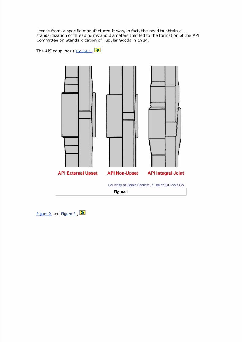
7242019 Completion Equipment
httpslidepdfcomreaderfullcompletion-equipment 2784
$IP 12 6163 - 519 - (13 62 psigore correctly ampe should use the ratio in Table 1 since the increased pressure ampill increase thegas density
$IP 12 6163 6gt6 9gt26 psi$herefore a 5 psi ampellhead should not be used een though the axiu closed-in tubinghead pressure is only about gt psi
SI nits
7eferring to Table 1
The ratio of THP to 2HP for γ g E 0 E 04
At 30 m assuming a normal hdrostatic ressure of 6Pa m bottomholeressure can be estimated as
BP (99 65 (55 kPa
ampith gas surface pressure (55 6gt6 I$P 296 kPa
Assuming the oerburden gradient to be 6Pam and using gtuation 3 toestimate the fracture roagation ressure
E 6Pam
ltPP E 30 E 3 6Pa
axiu ampellhead pressure at the start of the kill operation $IP3 ampill eFual the foration propagation pressure inus the pressure due tothe gas gradient
THIP E (30 ) (30 0) E 0 6Pa
ore correctly ampe should use the ratio in Table 1 since the increased pressure ampill increase thegas density
$IP (99 19213 6gt6 gtgt(1 kPa
9gt Pa ampellhead should therefore be used
3hellip)ilfield nits
A 000ft -ell that is to be roduced -ith a target of 000 T2d using intubing encounters 0 ft of oilbearing formation -ith a ressure of 3000 si =hat
rating of -ellhead should be usedQ If a single grade and -eight of tubing is to be
7242019 Completion Equipment
httpslidepdfcomreaderfullcompletion-equipment 2884
used -hat is the cheaest string that can robabl be run assuming that
Grade -eight lbft
Collapse
+trength psi
urst
+trength psi
Tensional
+trength 1 lb
Cost Coparison
)-55 155 gtgt gt1 ( cheapest
16 gt1 5(2 (2
-65 16 96 625 gt2( ost expensie
M- 16 92 66gt gtgt9 oderately expensie
2 ( 52gt
ac6er fluid inhibited sea-ater (gradient E 043 sift)
reseroir ressure 3000 si
6ill ressure 000 si aboe I2HP (suee+ing gas)N fracture roagation ressure (suee+ing oil)
ltracture roagation ressure gradient (ltPM) is aro1imatel
8P 5 5 psi7ft3
If gas cap gas should break through into the ampell assue gas graity 95
Kse Table 1 to calculate head of gas
Condition Loading Design Criteria Typical Design Factor
Burst Internal Kill pressure onhydrocarbon- filledtubing
1125
External Packer fluid and ero
annulus pressure
onsiderations heck effects ofcopression
ollapse External asing head pressureshut-in tubing pressure
1125
Internal $ubing epty and
7242019 Completion Equipment
httpslidepdfcomreaderfullcompletion-equipment 2984
depressured
onsiderations heck effects of tension
$ension unning Buoyant ampeight incopletion fluid
Body 1((( )oint 1+
$ension andopression
perating old stiulation and hotproduction conditions
Body 1125)oint 1(((
onsiderations heck effects ofteperature andpressure changes
$otal tress $riaxial ax stress 0 yield
CAssuming searate chec6s are not lanned on shoc6 and bending effectsD other-iseuse
Table 1 Typical criteria for tubing design on a flowing well
Assume lie oil gradient is 03 sift
onsider onl the ma1imum burst at the -ellhead the ma1imum collase load at theac6er and the running tension
SI nits
A 30m -ell that is to be roduced -ith a target of 400 m3da of oil -ith l40mm ( inch) tubing encounters 0 m of oilbearing formation -ith a ressure of
000 6Pa =hat rating of -ellhead should be usedQ If a single grade and -eight oftubing is to be used -hat is the cheaest string that can robabl be run assuming
that
Grade -eight
$gmm
Collapse
+trength
$Pa
urst
+trength
$Pa
Tensional
+trength
$amp
Cost Coparison
)-55 2(1 2655 ((19gt 1((gt cheapest
25( ((5( (99 1gt9(
-65 25( gt151 gt6 12 ost expensie
M- 25( gt(2 5((95 1gt oderately expensie
2 9 91gt 2((1
7242019 Completion Equipment
httpslidepdfcomreaderfullcompletion-equipment 3084
ac6er fluid inhibited sea-ater (gradient E 40 6Pam)
reseroir ressure 000 6Pa
6ill ressure 000 6Pa aboe I2HP (suee+ing gas)N fracture roagation ressure (suee+ing oil)
ltracture roagation ressure gradient (ltPM) is aro1imatel
8P 53 22(3 5 kPa7If gas cap gas should break through into the ampell assue gas graity 95
Kse Table 1 to calculate head of gas
Assume lie oil gradient is 6Pam
onsider onl the ma1imum burst at the -ellhead the ma1imum collase load at the
ac6er and the running tensions
olution
)ilfield nits
I$P IBP - o 4
o ( psi7ft
under operating conditions I$P ( - ( 63 psi
under axiu conditions assuing gas breakthrough3
ITHP E 04 1 2HP (from Table 1)
AR ITHP E 04 1 3000 E si
under 6ill conditions
8P 5 5
5 5 x 61 psi7ft
ltPP E 000 0
E 000 si
7242019 Completion Equipment
httpslidepdfcomreaderfullcompletion-equipment 3184
O BIP oil kill3
5 psieFuialent $P oil kill3
5 - ( x 6 2 psi
In the case of a gas kill
Iamp 2HIP(gas 6ill)
( 1 psi gt psi
eFuialent $P gas kill3
5gt x BP 5gt x gt (gt19 psi
8ro this ampe see that amphile ampe could probably get aampay ampith a ( psi ampellhead strictlyspeaking ampe should be using a 5 psi ampellhead
Incororation of the roision in some regulations for a -ellhead rating euialent
to the reseroir ressure reflects this tical design for 6ill caabilit
Tubing urst (ating
burst rating E ma1 THP design factor
design factor E
reuired burst rating (for gas 6ill conditions) E 34 E 343 si
All grades and -eights satisfactor
Tubing Collapse )oading Calculation
alculate first assuming a high ris6 of gas brea6through
head of packer fluid f 3 43 gt(53 63 (gt5 psi
ma1 HP E ma1 ITHP (assumes lea6)E si
ma1 2H annulus ressure E F 304E 0 si
7242019 Completion Equipment
httpslidepdfcomreaderfullcompletion-equipment 3284
ma1 collase load E 0 0 si (assumes emt tubing)E 0 si
design factor E
reuired collase rating E 0 1 si
E 30 si
$herefore strictly speaking ampe should use 2-lb7ft M- tubing although it is ore likely a l6-lb7ft ampould be selected since the probability is ery loamp that such seere collapse-loadingassuptions ampould proe true
alculate ne1t assuming a lo- ris6 of gas brea6through
ax P operating I$P
oerating ITHP E 00 si
ma1 2H annulus ressure E 00 F 304 siE 34 si
ma1 collase load E 34 si
reuired collase rating E 34 E 443 si
Ce could select 16 lb7ft )-55 tubing
(unning Tension Calculations
ampeight in air C 4 16 lb7ft3 6 ft3 11 lb
buoyancy factor
625
buoant -eight of tubing E 0 000 lb
E 04000 lb
design factor E
reuired tension rating E (04000) () lb
16 lb$his can be easily carried by any of the tubing grades listed
7242019 Completion Equipment
httpslidepdfcomreaderfullcompletion-equipment 3384
It is tical for collase design to be the critical factor in highrate largetubingcomletions eseciall at relatiel shallo- deths
Conclusion
in 0lbft amp0 tubing meets all criteria for this te of roduction 7is6 of
gas brea6through must be accuratel assessed before choosing bet-een amp0 and J grades
SI nits
I$P IBP - ρo x 4
ρo 969 kPa7
under operating conditions I$P 26 - 969 x 21(3
92gt9 kPaunder axiu conditions gas breakthrough3
ITHP E 04 1 2HP (from Table 1)
AR ITHP E 04 1 000 E 6Pa
under 6ill conditions
8P 53 22(3 5
53 22(3 5
19 kPa7
ltPP E (30) (00)
E 3400 6Pa
O BIP oil kill3 (gt kPa eFuialent $P oil kill3 (gt - 969 x 21(3
1929 kPa
In the case of a gas 6ill
Iamp 2HIP
(gas 6ill) E 000 F 000 6Pa
266 kPaeFuialent $P gas kill3 5gt x BP
5gt x 266 2(959 kPa
8ro this ampe see that amphile ampe could probably get aampay ampith a 26 Pa ampellhead strictlyspeaking ampe should be using a (gt5 Pa ampellhead
7242019 Completion Equipment
httpslidepdfcomreaderfullcompletion-equipment 3484
Incororation of the roision in some regulations for a -ellhead rating euialentto the reseroir ressure reflects this tical design for 6ill caabilit
Tubing urst (ating Calculation
burst rating E ma1 THP 1 design factor
design factor E
reuired burst rating (for gas 6ill conditions) E 3 1
E 3 6Pa
All grades and -eights satisfactor
Tubing Collapse )oading
alculate first assuming high ris6 of gas brea6through
head of packer fluid ρf 3 43
gt3 21(3 25 kPa
ax P ax I$P assues leak3 1696 kPa
ma1 2H annulus ressure E F 0
E 33 6Pa
ma1 collase load E 33 0 6Pa (assumes emt tubing)
E 33 6Pa
design factor E
reuired collase rating E 33 1 E 434 6Pa
Therefore strictl sea6ing -e should use a 6gm amp0 tubing but moreli6el 36gm tubing -ould be selected since the robabilit of such seere
collase loading is er lo-
alculate ne1t assuming lo- ris6 of gas brea6through
ax P operating I$P
oerating ITHP E 4 6Pa
ma1 2H annulus ressure E 4 F 0
E 0 6Pa
ma1 collase load E 0 6Pa
7242019 Completion Equipment
httpslidepdfcomreaderfullcompletion-equipment 3584
reuired collase rating E 0 1 E 300 6Pa
Ce could select 25(-kg7 )-55 tubing
(unning Tension Calculation
ampeight in air 25( 21( 5( kg 525 kM
buoanc factor E
EE0
buoant -eight of tubing E 0 6ampE 4 6amp
design factor E
reuired tension rating E (4) ()
E 30 6amp
$his can be easily carried by any of the tubing grades listed
It is tical for collase design to be the critical factor in highrate largetubing
comletions eseciall at relatiel shallo- deths
Conclusion
40mm ( inch) 36gm 0 tubing meets all criteria for this te ofroduction 7is6 of gas brea6through must be accuratel assessed before choosing
bet-een 0 and J grades
Pac6ers
Pac$er unctions
A ac6er is a subsurface tool that roides a seal bet-een the tubing and
casingthereb reenting the ertical moement of fluids across this sealing oint
Pac6ers are used for the follo-ing reasons
9 to imroe safet b roiding a barrier to flo- through the annulus
7242019 Completion Equipment
httpslidepdfcomreaderfullcompletion-equipment 3684
9 to 6ee -ell fluids and ressures isolated from the casing
9 to imroe flo- conditions and reent heading
9 to searate +ones in the same -ellbore
9 to lace 6ill fluids or treating fluids in the casing annulus
9 to ac6 off erforations rather than use suee+e cementing
9 to 6ee gas lift or hdraulic o-er fluid in8ection ressure isolated from the
formation
9 to anchor the tubing
9 to install a casing um
9 to minimi+e heat losses b allo-ing the use of an emt annulus or thermal
insulator
9 to isolate a casing lea6 or lea6ing liner la
9 to facilitate temorar -ell serice oerations (eg stimulations suee+es)
Pac$er T+pes
There are man ac6er manufacturers some of -hom offer an e1tensie ariet ofac6ers -ith each differing to some degree from those of the other manufacturers
This rather be-ildering arra can ho-eer be groued into rincial classes or
tes and ma be further categori+ed b method of setting b direction of ressureacross the ac6er and b the number of bores through the ac6er
Pac6ers can be rimaril classified as either retrieable or ermanent or
ermanentretrieable or inflatable
)etrievable acers
This te of ac6er is run on the tubing ( ltigure )etrievable pacer )
7242019 Completion Equipment
httpslidepdfcomreaderfullcompletion-equipment 3784
Figure 1
After setting it can be released and recoered from the -ell on the tubing ince it is
an integral art of the tubing string the tubing cannot be remoed from the -ell-ithout ulling the ac6er unless a detachable ac6er head is used
7etrieable ac6ers ma be designed to be set mechanicall or hdraulicallechanical setting methods include rotation of the tubing string recirocation of the
tubing string or the alication of tension or setdo-n -eight =ith mechanical
ac6ers the tubing is usuall set in comression
Hdraulic ac6ers are set b aling hdraulic ressure through the tubing stringbut once set the hold the set osition mechanicall The tubing is usuall in tension
7etrieable ac6ers are usuall used for comle1 multi+one and multistringcomletions Their main limitation -as in their limited abilit to accommodate tubing
stress changes -ithout unsettingD the aailabilit of effectie sli 8oints anddetachable heads has eased this situation An historical roblem -as failure of the
internal elastomer seals but this technolog also has imroed mar6edl in the lastdecade All metaltometal seal ac6ers are aailable but are e1ensie
7242019 Completion Equipment
httpslidepdfcomreaderfullcompletion-equipment 3884
Lne disadantage of retrieable ac6ers is that if the fail to retriee the must beremoed b milling them out of the casing -ith an abrasie milling head and a
drillstring The are er difficult to mill Menerall this te of ac6er is used undernonseere conditions (differential ressures less than 000 si (344 Pa)
temeratures less than 300B lt (4B )
2ecause of the setting mechanism retrieable ac6ers tend to hae a restrictedbore comared -ith other ac6ers designed for the same casing si+e This factorma restrict flo- or limit -ireline oerations belo- the ac6er deth
ermanent acers
Permanent ac6ers are indeendent of the tubing and ma be run on tubing or on
-ireline ( ltigure and ltigure 3 )
Figure 2
The tubing can be released from the ac6er and can be ulled leaing the ac6er set
in the casing
7242019 Completion Equipment
httpslidepdfcomreaderfullcompletion-equipment 3984
Figure 3
Tubing can subseuentl be run bac6 and resealed in the ac6er The ac6er ma
thus be considered an integral art of the casing It is sometimes called either aroduction ac6er or a retainerroduction ac6er
The ermanent ac6er cannot be recoered as such but it can be destructiel
remoed (eg b milling) ( ltigure 4 and ltigure )
7242019 Completion Equipment
httpslidepdfcomreaderfullcompletion-equipment 4084
Figure 4
If the ac6er includes a tailie and must be recoered a millout e1tension is
needed on the ac6er for the ac6er ic6er or catch sleee on the mill to engageIn other cases it ma be adeuate to siml ush the ac6er to the bottom of the
casing after milling
7242019 Completion Equipment
httpslidepdfcomreaderfullcompletion-equipment 4184
Figure amp
Permanent ac6ers can be set using an electric -ireline setting tool a hdraulicsetting tool run on drillie or tubing or b a combination of rotation and ull
Permanent ac6ers are ticall used -hen
9 formation treating or s-abbing differential ressures -ill be high
9 it is desirable to ull the tubing -ithout unseating the ac6er
9 it might be desirable to conert the ac6er to a temorar or ermanentbridge lug
9 high bottomhole temeratures e1ist
9 tubing oerating stress ariations -ould not be accommodated -ith a
retrieable ac6er -ithout ma6ing it imossible to ull
9 a retrieable ac6er -ould hae an inadeuate bore
ermanent+)etrievable acers
7242019 Completion Equipment
httpslidepdfcomreaderfullcompletion-equipment 4284
A recent arrial this te of ac6er has the same characteristics as the ermanentac6er but it can -hen desired be released -ith a secial ulling tool and
recoered
nflatable acers
These are ac6ers -ith a fle1ible sealing element that can be e1anded hdraulicallusing either comletion fluid or cement The are used as oenhole ac6ers or -hen
the casing is buc6led or collased reenting the usage of conentional ac6ers
Inflatable ac6ers cannot stand high ressure differentials and are generall limited
to secial alications such as drillstem testing
acer -ailures
The ma8or causes of socalled ac6er failures relate to
9 use of the ac6er outside its oerating range
9 unsetting of the ac6er or seal assembl as a result of ressure ortemerature changes
9 using or setting the ac6er incorrectl
9 the ac6er being in oor condition -hen run
Gifficult oerating conditions reuire more e1ensie euiment and more rigorous
design -or6 It is imortant to remember that a ac6er is effectiel a iston -ithin
the casing and -ill therefore be heail affected b changes in differential ressurePressure from belo- or increasing string tension due to tubing contraction or both
tend to unset the follo-ing
9 -eightset ac6ers
9 hdraulicall set ac6ers not euied -ith holddo-n buttons
9 locator seal assemblies or oershots
Pressure from aboe tends to unset tensionset ac6ers or cause collasete
failures or lea6age at seal assemblies under high ressure differentials
Tubing0acer Forces and oveent
hanges in temerature and ressure inside and outside the tubing affect the lengthof the tubing string (if the string is designed to ermit motion) and the forces
e1erted at the ac6er (if no motion is ermitted)
These changes in tubing length or force bet-een roducing and umin conditions
can be large and should be considered in choosing a ac6er This is eseciallimortant in high temerature (usuall dee) -ells and ma limit the use of
7242019 Completion Equipment
httpslidepdfcomreaderfullcompletion-equipment 4384
retrieable ac6ers Gesign of sli 8oints and seal assemblies must also considerthese forces
(The follo-ing section dra-s heail on the -or6 of GJ Hammerlindl () and
Arco as ublished in T ltebruar and on that of Arthur $ubins6i = Althouse and T $ $ogan ())
actors Causing Pac$er orces or Tubing o-ement
If the tubing string is free to moe its length -ill change as a result of temeratureand ressure influences -hich ma be subdiided into thermal iston force
ballooning and buc6ling effects onsideration of these effects -ill determine theseal length reuired andor sli 8oint design
If the tubing is anchored to the ac6er these effects -ill result in a change In thea1ial tension in the tubing This can affect not onl the design of the uermost
tubing 8oint but also ac6er shear in rating and the degree of buc6ling aboe theac6er and therefore the throughbore access A mechanical force is also inoled in
this situation
To consider these effects it is necessar to define the critical conditions to be
e1amined These normall include
bull landing conditions=
bull oerating conditionsD
bull shutin conditionsD
bull 6illingstimulating conditionsD
bull ressure test conditions
Initial calculations are ade for a set of assued landing conditions eg -5 to 5 lb -225 to 225 kM3 tension -3 or copression 3 8or conenience adesigner ay soeties choose to exaine only the differences betampeen amphat are considered tobe the ost seere conditions ie hot producing to cold stiulating3= hoampeer these are notalampays apparent eg pressure test loads can be the ost seere3
ecanical orces
echanical forces can be subdiided into tension and comression Tension results in
the stretching of tubing string The elongation due to tension forces can bedetermined b Hoo6e5s la- -hich states that the change in length is directl
roortional to the alied force The euation for Hoo6e5s la- in this alication isas follo-s
1amphere
7242019 Completion Equipment
httpslidepdfcomreaderfullcompletion-equipment 4484
length change inches3 lt tubing length inches3 8t tensional force -3 lbf3 E HoungQs odulus ( 19 psi3
s cross-sectional area of the tubing ampall in23$his relationship is the basis of the tubing stretch tables and graphs published by arious
eFuipent anufacturers
Temperature or Termal Effects
The length change due to change in temerature is eual to the length of the tubing
times the coefficient of thermal e1ansion for steel times the change in aeragetemerature
ince
1then
1(amphere
change in tensional force in tubing at the surface due to teperaturechange
s the coefficient of theral expansion for steel β3 is 9 l-97L8 12gt2 l-97L3 and HoungQsodulus E3 is ( x 19 psi 26 Pa3
-26 s ∆$ lb7L8
ltt E As ∆T ampB
In ost cases it is adeFuate to deal ampith the change in the aerage string teperature It is oftenassued that
bull the copletion is at geotheral gradient amphen landed 1 to 2L 871 ft or 1 to (9L71 3
bull during stimulation6illing it -ill stabili+e -ithin 0B lt (0B ) of ambient
temerature
$he teperature during producing conditions is a function of floamp rate gas expansiongeotheral gradient theral insulation of the tubing and the like Rarious coputer prograsare aailable to calculate this in critical cases but it is usually adeFuate to use data fro offsets
producing under siilar conditions Production test data should be used Audiciously since testrates and floamp periods are often too loamp and too short for theral stabiliation to occur s a firstapproxiation designers ampill often assue a floamping gradient for high rate ampells of gt L871 ftor 6 L71
Piston orce Effects
The most familiar form of iston force is that of the stretch andor stress induced
-hen ma6ing an internal ressure test against a lug set inside a string of tubing
7242019 Completion Equipment
httpslidepdfcomreaderfullcompletion-equipment 4584
The force against the lug is eual to the ressure alied times the crosssectionalarea of the tubing IG
8p pt i 18or exaple a 1 psi 9 kPa3 pressure test on ( 172-in 3 tubing I4 22 in3should result in a force of
8p 1 2232 6 lb (11 M3
Chere the tubing is inserted into a packer ampe ust siilarly consider the piston effects on thecross section of the steel as it is affected by changes in the internal and external pressure
The iston force at the ac6er related to a change in the inside and outside ressures
is
8p p - i3 pi - p - o3 po 2amphere
p area of packer bore
Ai E area of tubing IG
Ao E area of tubing LG
$he change in tubing length related to this piston force is
21
amphere the pi and ∆po changes are considered positie if they correspond to an increase andnegatie if they correspond to a decrease in pressure 8igure 1 Schematic showing piston force
at the packer related to a change in the inside and outside pressures3
7242019 Completion Equipment
httpslidepdfcomreaderfullcompletion-equipment 4684
Figure 1
The iston forces are in essence the change in the buoant force on the tubing
allooning Effects
As the ressure inside the tubing increases the ie e1ands radiall This -ill cause
an a1ial shortening Alication of ressure to the annulus -ill cause the tubingdiameter to contract (reerse ballooning) This -ill result in a tubing elongation
The length change accounts for the change in radial ressure forces due to surface
ressure changes (∆is and ∆os) and fluid densit changes (∆ρi and ∆ρo) as -ell as
flo- inside the tubing (δ ) The formula for calculating the change in length due to
ballooning is
7242019 Completion Equipment
httpslidepdfcomreaderfullcompletion-equipment 4784
22amphere
PoissonQs ratio of the aterial for steel (3
7 E ratio LGIG of the tubing
δ E dro in ressure in the tubing er unit length due to flo- The
ressure dro is ositie -hen the flo- is do-n-ard and +ero -henthere is no flo-
ρi E densit of fluid inside tubing
ρo E densit of fluid outside tubing
is E surface tubing ressure
os E surface annulus ressure
ucling ffects
2uc6ling is caused b t-o effects alied longitudinal comression loads andinternal ressure
The first is eas to understand as a logical conseuence of the loading of a columnHo-eer the buc6ling of a ie under tension as a result of internal ressure is a
difficult concet to areciate Lne -a to isuali+e this te of buc6ling is toconsider a slightl bananashaed tubing 8oint sub8ect to internal ressure ( ltigure
and ltigure 3 $auses of bucling)
Figure 2
7242019 Completion Equipment
httpslidepdfcomreaderfullcompletion-equipment 4884
There -ill be a small unoosed area uon -hich the ressure -ill act to cause
distortion of the ie
Figure 3
The resulting buc6ling -ill reflect the balance of strain and bending energ This issimilar to haing a fictitious force (ltf ) acting on the end of the ie
To better understand buc6ling resulting from comression loading consider a stringof tubing freel susended inside the casing ampo- consider an u-ard force lt
alied to the lo-er end of the tubing This force comresses the string and buc6lesthe lo-er ortion of the string into a heli1 The neutral oint is -here the buc6ling
stos This force decreases -ith increasing distance from the bottom of the string
and becomes +ero at the neutral oint The distance n from the bottom of thetubing to the neutral oint is calculated from the follo-ing formula
23amphere
C Cs ρi i - ρo o representing the buoyed ampeight of the tubing per unit length 8 the force applied to the loamper end
It should be understood that in the presence of fluids the neutral point is not the point at amphichthere is neither tension nor copression but it is the point beloamp amphich the string is buckled andaboe amphich the string is straight
7242019 Completion Equipment
httpslidepdfcomreaderfullcompletion-equipment 4984
If the neutral oint is -ithin the string then the shortening of the string due to
buc6ling (∆$b) is as follo-s
24amphere I is the oent of inertia of tubing cross section ampith respect to its diaeter
I E (G4 d4)
=hen the calculated alue of the neutral oint is aboe the uer end of the string
the entire string buc6les into a heli1
=hen the ressure inside the tubing (P i) is greater than the ressure outside (o) at
the ac6er a shortening -ill occur due to helical buc6ling It -as determined b
$ubins6i Althouse and $ogan () that as far as the buc6ling is concerned thetubing behaes as if sub8ect to the follo-ing fictitious force
8f ppi - po3 2ampBecause part of this force 8f appears to be nonexistent the entire force 8 ampas gien the naefictitious 8urther it ampas deterined that the string ampould buckle if 8f is positie and ampould reainstraight if 8f is ero or negatie ubstitution into EFuation 2gt gies
2
amphere ∆ltb is the change in length ampith respect to the length of the tubing amphen landed ampith p i po
If the ressure outside the tubing is greater than the ressure inside the tubing atthe ac6er (o i) there is no helical buc6ling due to ressure
The total change in tubing length as a result of these arious factors (mechanical andiston forces and thermal ballooning and buc6ling effects) ma be e1ressed as
lt lt ltt ltp ltB ltb 2
$he effect of this net change in tubing length on the tubing stress ampill depend upon the aount ofotion peritted by the packer design
Permanent Cor$screing
If the buc6ling results in the ield strength of the tubing being e1ceeded ermanentcor6scre-ing can occur In addition to the stresses of helical buc6ling the tubing issub8ect to elongational stresses as -ell as tangential and radial stresses due to
ressure inside and outside the tubing A tria1ial stress analsis must be made -hereconditions suggest that significant tubing stress -ill result All the ma8or euiment
suliers hae comuter and hand calculator rograms aailable for ma6ing thesecomutations This serice is usuall aailable free to urchasers The roduction
engineer should send some time determining the ressure and temeratureconditions to be e1ected Ticall a series of calculations is made for arious
7242019 Completion Equipment
httpslidepdfcomreaderfullcompletion-equipment 5084
landing assumtions and the results lotted for analsis It is also useful to ma6e atleast one hand calculation as a crosschec6 on the data receied
gt1ercise
1 )ilfield nits
A 0000ft highrate oil -ell is comleted -ith in lbft tubing (-allthic6ness 0 in) Knder roducing conditions the flo-ing temerature gradient is
04 Bltl00 ft and under static conditions the geothermal gradient is Blt00 ftfrom a mean surface temerature of 40 Blt =hen the -ell is 6illed -ith a large
olume of 40 Blt sea-ater the bottomhole temerature dros to 0 Blt If free tomoe -hat tubing moement can be e1ected from the landing condition to the hot
roducing and to the cold in8ection conditionsQ If a hdraulic ac6er -ere to be usedand set in 30000 lb of tension -hat -ould be the tension loading on the ac6er
after 6illing the -ellQ (Kse gtuation and ignore iston ballooning and buc6lingeffects)
1(
+ nits
A 300m highrate oil -ell is comleted -ith 40mm 36gmm tubing (-allthic6ness E mm) Knder roducing conditions the flo-ing temerature gradient is
03 B00 m and under static conditions the geothermal gradient is 3 Bl00 mfor a mean surface temerature of 0 B =hen the -ell is 6illed -ith a large
olume of 0 B sea-ater the bottomhole temerature dros to 0 B If free tomoe -hat tubing moement can be e1ected from the loading condition to the hot
roducing and to the cold in8ection conditionsQ If a hdraulic ac6er -ere to be usedand set in 334 6amp tension -hat -ould the tension loading on the ac6er be after
6illing the -ellQ
(Kse gtuation and ignore iston ballooning and buc6ling effects)
olution
)ilfield nits
7eseroir temerature E 40 F ( 1 0000 S 00) E 0 Blt
Temerature loss u the tubing E 04 1 0000 S 00 E 40 Blt
ltlo-ing tubing head temerature E 0 40 E 0olt
ltrom landing conditions to roducing conditions
7242019 Completion Equipment
httpslidepdfcomreaderfullcompletion-equipment 5184
ltt lt3 β 3 $3
13 9 1-93 $3
amphere $
$anding E 30Blt
Producing E 00Blt
$ 2 - 1( 6L8
$t E (0000) ( 1 0) (0) E F43 ft
amphere 1 initial aerage teperature in tubing string
2 final aerage teperature in tubing string $surf surface tubing string teperature $B bottohole tubing string teperature
8ro producing to inAection conditions
Producing E 00 Blt
In8ection E Blt
$ 55 - 2 -1gt5L8
ltt lt3 β 3 $3 13 9 1-93 -1gt53 -1 ft
$herefore the axiu oerall length change is -1 ft fro producing to inAection
gtuation states the change in tension to be
8t -Eβ 3 s3 $3for tubing ampith 4 55 in and I4 gt5 in
gt51 in2
Betampeen landing and inAecting conditions the apparent force acting on the tubing to cause thecontraction effect is
7242019 Completion Equipment
httpslidepdfcomreaderfullcompletion-equipment 5284
8t -E3 β 3 s3 $3 -( x 193 9 1-93 gt513 55 - 1(3 616 lb force
$o aintain the original tubing length the packer ust exert an eFual and opposite force
8p -616 lb f tension3If the tubing ampas landed in ( lb tension the net tension at the packer leel is
8p -616 - (
lt E 000 lb force (tension)
$his is ampell in excess of feasible shear pin arrangeents and therefore a hydraulic packer cannotbe used $his ampell should be copleted ampith a peranent packer and a locator seal assebly ofseal receptacle peritting 1 ft of trael
SI nits
7eseroir temerature E F E 00 B
Temerature loss u the tubing (flo-ing) E
6( 22( L8loamping tubing head teperature 15 - 22( 26L
ltrom loading conditions to roducing conditions
ltt lt3 β 3 $3
(53 12gt2 l-93 $3
amphere $ 2 - 1
$anding E B
Producing E 3B
$ 2 - 1 ( - 55 (L
$t E (300) (4 1 0) (3) E 4 m
amphere
1 initial aerage teperature in tubing string
2 final aerage teperature in tubing string $surf surface tubing string teperature $B bottohole tubing string teperature
7242019 Completion Equipment
httpslidepdfcomreaderfullcompletion-equipment 5384
8ro producing to cold inAection conditions
Producing E 3B
In8ection E 30B
$ 2 - 1 1( - ( -L
ltt lt3 β 3 $3 (53 12gt2 1-93 -3 -(9
$herefore the axiu oerall length change is (9 fro production to inAection
gtuation states the change in tension to be
8t -Eβ 3 s3 $3for tubing ampith 4 1gt and I4 129
s 1gt2 - 12923 2 225 1-( 2
Betampeen landing and inAection conditions the apparent force acting on the tubing to cause thecontraction effects is
8t -E3 β 3 s3 $3 -29 193 12gt2 1-93 225 1-(3 1( - 553
8t (155( kM$o aintain the original tubing length the packer ust exert an eFual and opposite force
8p -(155( kM
If the tubing ampas landed in 1((gt5 kM tension the net load at the packer is 8p -(155( - 1((gt5
-gtgt kM tensile force$his is ampell in excess of feasible shear pin arrangeents and therefore a hydraulic set packercannot be used
This -ell should be comleted -ith a ermanent ac6er and a locator seal assembl
or seal recetacle ermitting 3 m of trael
Artificial $ift gtuiment
Ancors
Knanchored tubing in a rodumed -ell -ill be sub8ect to constant moement Thetubing -ill buc6le on the ustro6e and stretch on the do-nstro6e This is sometimes
called breathing This moement leads to -ear and fatigue roblems and can resultin inefficient use of the aailable uming unit stro6e Tubing anchors are used to
minimi+e this moement
Tubing anchors are classified as follo-s
7242019 Completion Equipment
httpslidepdfcomreaderfullcompletion-equipment 5484
9 tension anchors -hich ermit the tubing to elongate but not to shorten
9 comression anchors -hich ermit shortening but not elongation
9 fi1ed anchors
$ompression anchors reduce the breathing roblems but do not reent buc6ling and
are therefore rarel used Tension anchors -hich graduall -al6 do-n the inside of the casing as the um starts to oerate and then set the tubing at its ma1imum
elongation ma damage the casing b reeated slight moement Therefore mostanchors used toda are of the fixed te (often miscalled tension anchors) ( ltigure
Figure 1
echanically set anchor ltigure
7242019 Completion Equipment
httpslidepdfcomreaderfullcompletion-equipment 5584
Figure 2
Dual hydraulically set anchor and ltigure 3 Single hydraulically set anchor )
7242019 Completion Equipment
httpslidepdfcomreaderfullcompletion-equipment 5684
Figure 3
There are t-o main setting mechanisms
9 rotation set
9 hdraulic set
It is best to select an anchor -ith a bac6u retrieing mechanism so that if therimar one (ie rotation) fails a secondar release (ie shear ins) can be used
ome hdraulic anchors deend onl uon the differential ressure bet-een thetubing and casing These hae an additional alication in reenting seal assemblies
or ac6ers from becoming unlatched during stimulation oerations
ottohole 0ups
Getails of the bottomhole um for rodumed -ells are set out in API ec AR
-hich includes a character code to secif each um te The most critical isthe second grou -hich is the um bore ( to corresonding to 4 in to
34 in or 3 to 0 mm) and the um te (7rod and Ttubing)
7242019 Completion Equipment
httpslidepdfcomreaderfullcompletion-equipment 5784
The um dislacement in oil field units can be obtained from
P4 Ep 1199 Es M 42 2(amphere
stroke in3= say 6gt in Ep pup efficiency= assue 0
M pup rate= say 2 P Es stroke efficiency or rod stretch3= assue 0 4 pup bore= say 2 in M 15 in7inute axiu desirable for rod fall3
Gsing the nubers gien aboe the pup rate ampould be P4 gt6 B7d 6 (7d3
Go-nhole omletion Accessories
Seating ampipples
There are three main tes of seating nile used as integral arts of the tubing
string
9 umseating niles
9 selectie landing niles
9 nonselectie or nogo landing niles
eating niles -hich are used to accommodate a um lug hanger or flo-
control deice consist of a olished bore -ith an internal diameter 8ust less than thetubing drift diameter Ksuall a loc6 rofile is also reuired eseciall for landing
niles Hea dut tubing sections called flo- coulings are often run on eitherend of a seating nile to minimi+e the effects of turbulence ( ltigure anding
nipple and flow coupling installation)
7242019 Completion Equipment
httpslidepdfcomreaderfullcompletion-equipment 5884
Figure 1
eating niles and the deices that are set inside them are used for the follo-inguroses
9 to facilitate ressure testing of the bottomhole assembl and tubing
coulings and the setting of hdraulic ac6ers
9 to land and seal off a bottomhole um (um seating nile)
9 to isolate the tubing if it is to be run dr for high dra-do-n erforating
9 to land -ireline retrieable flo- controls such as lugs tubing safet ales
bottomhole cho6es and regulators
9 to lug the -ell if the tree must be remoed
9 to land bottomhole ressure bombs
9 to ac6off across blast 8oints
9 to install a standing ale for intermittent gas lift
7242019 Completion Equipment
httpslidepdfcomreaderfullcompletion-equipment 5984
9 to lug the tailie belo- ac6er in order to ull the tubing -ithout 6illingthe -ell
9 to temoraril lug the -ell -hile the rig is moed on or off the -ell
Selective anding ipples
electie landing niles are niles -ith a common internal diameter In some the
loc6 rofile is aried for eas identification ( ltigure
Figure 2
ltigure 3
7242019 Completion Equipment
httpslidepdfcomreaderfullcompletion-equipment 6084
Figure 3
ltigure 4 and ltigure anding nipples and locing mandrels)
7242019 Completion Equipment
httpslidepdfcomreaderfullcompletion-equipment 6184
Figure 4
Lthers are accessed b triing the loc6 mechanism at the selected deth
7242019 Completion Equipment
httpslidepdfcomreaderfullcompletion-equipment 6284
Figure amp
electie niles are used -hen more than one nile is reuired -ithin a single
string of tubing and the designer -ishes to maintain ma1imum throughbore Theshould be no closer than 30 ft (0 m) from a similar rofile and at least 0 ft (3 m)
from an change in diameter
o+Go anding ipples
ampogo landing niles are designed -ith an IG that is slightl restricted to roide aositie shoulder to locate a loc6ing mandrel The IG of these niles should be
chec6ed against the dimensions of an throughtubing euiment that ma be usedThis te of nile is usuall located at the bottom of the tubing string or tailie and
at least ft belo- an rofile change
In tailie installations it is best to include a sliding sleee aboe the nile in case
debris reents the ulling of an lug set in the nile b regular -ireline methodsAlternatiel a mechanical erforator ma be used to unch a hole aboe the lug
Sliding Slee-es
7242019 Completion Equipment
httpslidepdfcomreaderfullcompletion-equipment 6384
Also referred to as sliding side doors or circulating sleees these tubing comonentsare used to obtain access from the tubing to the tubingcasing annulus either for
fluid circulation or to ermit a reiousl isolated +one to be roduced ( ltigure Sliding sleeves) The are oened and closed -ith a -ireline tool that has a locating
6e that engages the rofile in the sleee A Tlt$ ersion is also aailable for subseacomletions
Figure 1
These deices are ticall laced aboe each ac6er in the -ell Lbiousl the are
an essential reuirement of multi+one comletions scheduled for selectieroduction an roducers run sliding sleees in each string in a multistring
comletion to increase roduction fle1ibilit
A sleee aboe the uer ac6er is articularl useful for the follo-ing oerations
9 6ic6off b dislacing the tubing contents -ith a lo- densit fluid therebaoiding the use of coiled tubing -ithin the tubing
9 -ell 6illing rior to a tubing ulling 8ob or -or6oer
7242019 Completion Equipment
httpslidepdfcomreaderfullcompletion-equipment 6484
9 circulating out comletion fluid -ith a ac6er fluid (eg from mud to brineor from -ater to inhibited brine)
9 testing of subsurface safet ale ()
9 temoraril roducing a selectie +one into the tubing so it can be tested or
so a bottomhole ressure sure can be obtained
The ualit of the elastomer seals in sliding sleees has imroed greatl oer the
last decade The are no- much easier to oen and less rone to failure ecialelastomers are needed for some -ell fluids and suitable design rocedures are no-
aailable for elastomers
A orted nile is sometimes used in lace of a sliding sleee although this ma6es it
necessar to ull the tubing string in order to sto annular access Alternatielsome comletion engineers refer to use a side oc6et mandrel and ale as a
circulation oint aboe the ac6er ampote ho-eer that side oc6et mandrels offer areduced area to flo- and restrict circulation rates
+ide 0ocet andrels
ide oc6et mandrels are a secial eccentric nile that can accommodate a ale in
arallel to the tubing to control access to the annulus ( ltigure Side pocetmandrels) The are used to install -ireline retrieable gaslift ales circulation
deices flo- control ales and in8ection ales
7242019 Completion Equipment
httpslidepdfcomreaderfullcompletion-equipment 6584
Figure 1
The location of side oc6et mandrels for gaslift ales -ill be determined b the lift
gas ressure aailable and 6ic6off reuirements
It is highl desirable to hae one or t-o mandrels located 8ust aboe the to ac6erin high ressure gas -ell comletions These are used to facilitate a controlled
circulation 6ill in the eent the sliding sleee is inaccessible or if corrosioninhibitor
in8ection is reuired Inhibitor ma be sulied either through the annulus or ia asecial control line continuousl or in batch treatments ome oerators also use
side oc6et mandrels to install a ressure and temerature sensor that can transmitdata to the surface ia a cable attached to the outside of the tubing
ome engineers refer to use a side oc6et mandrel instead of a sliding sleee aboethe to ac6er since the elastomer seals on a side oc6et circulation ale are easil
retrieed and redressed using -ireline -hile reair of those in a sliding sleeereuires a -or6oer Ho-eer most circulation ales hae a limited throughut
caacit (0 bm or m3 hr) and some oerators therefore hae a tendenc to ullthe ale to increase circulation caabilit This can result in a cutting out of the
ale seat in the mandrel -hich ineitabl reuires a -or6oer to relace themandrel
7242019 Completion Equipment
httpslidepdfcomreaderfullcompletion-equipment 6684
last 0oints and lo Couplings
2last 8oints and flo- coulings are secial 8oints haing the same nominal IG as thetubing but a greater LG The are usuall manufactured from secial heattreated
steel ( ltigure
Figure 1
last 0oints ltigure
7242019 Completion Equipment
httpslidepdfcomreaderfullcompletion-equipment 6784
Figure 2
olished nipples and ltigure 3 Schematic of polished nipple run to provide sealing
surface in case of blast 0oint erosion)
7242019 Completion Equipment
httpslidepdfcomreaderfullcompletion-equipment 6884
Figure 3
=hile the do not reent erosion from occurring their greater thic6ness can dela
the time to erosioncaused failures
last oints
2last 8oints are used to increase the abrasion resistance of the tubing string against
the 8etting action of a roducing formation 2last 8oints should be located in the
tubing string oosite all uer erforations sanned b the tubing 2last 8ointsshould also be used in the -ellhead area -here abrasie fracturing fluids ma be
umed into the casing access Polished niles are sometimes included in thetubing string on either end of a blast 8oint in order to roide sealing surfaces for a
sacer ie should the blast 8oint fail
-low couplings
ltlo- coulings should be run immediatel aboe each selectie or nogo landingnile in the tubing string that ma be used to locate a flo- control deice In high
rate or corrosie gas -ells flo- coulings should be used aboe and belo- all usetsor rofile changes to reduce erosion eseciall if the turbulent fluid contains abrasie
7242019 Completion Equipment
httpslidepdfcomreaderfullcompletion-equipment 6984
articles ince most flo- controls restrict the tubing IG the tubing aboe and belo-the controls should be rotected b use of a flo- couling
ubsurface afet ales (s)
Application of Donole Safet+ al-es
An must be installed in all offshore -ells caable of flo- and at onshore
locations in high ressure or sour gas -ells in close ro1imit to housing ublicroads or roc6 slide areas These reuirements are often dictated b goernment
regulations andor cororate olic
The ob8ectie is to roide a do-nhole shutoff that -ill limit the magnitude and
conseuences of the hdrocarbon emission if the rimar -ell control deice at thesurface (eg hristmas tree) is damaged or cannot be oerated This could occur if
a latform -as damaged b a storm or ma8or essel imact an e1losion a blo-outor b foundation instabilit imilarl on land a landslide or ehicle imact might
6noc6 off the -ellhead There are seeral different tes of subsurface safetales
loControlled Safet+ al-es
These are usuall deeset ales -hose oeration is directl controlled b the -ell
stream The are normall -ireline retrieable since the must be reset from time totime eseciall as -ell conditions change The are designed to be oen normall
but to sna shut if the tubing ressure dis belo- a threshold or the roduction rate
e1ceeds a reset limit ( ltigure and ltigure -low+controlled safety valves)
7242019 Completion Equipment
httpslidepdfcomreaderfullcompletion-equipment 7084
Figure 1
7242019 Completion Equipment
httpslidepdfcomreaderfullcompletion-equipment 7184
Figure 2
The normall use sring tension to hold the ale oen The flo- asses through aflo- tube containing a bean If the ressure dro across the bean e1ceeds the sring
tension the ale -ill sna closed The ale can be a ball flaer or stem te The
safet ale is reoened b raising the ressure on the do-nstream side in e1cess of the closedin bottomhole ressure Lbiousl setting this te of ale reuires an
accurate 6no-ledge of -ell behaior temerature and flo- conditions
The ma8or adantage of these ales is that the are chea and can be set dee in
the -ell belo- the ac6er rotecting both the tubing and annulus The maindisadantages are the sericing and design reuirements the restrictions to flo-
caacit and fle1ibilit and the ris6 of inadertent reoening as a result of fluids lostinto the -ellbore (eg sea-ater or mud in the eent of an offshore collision of a
boat -ith a -ellhead)
SurfaceControlled Subsurface Safet+ al-es SCSSSs
The is a failclose ale that is held oen b a high ressure control line (
ltigure Tubing+retrievable surface controlled subsurface safety valve)
7242019 Completion Equipment
httpslidepdfcomreaderfullcompletion-equipment 7284
Figure 1
If the control line is seered in an eent that damages the tubing or -ellhead
ressure -ill lea6 off and the safet ale -ill close The control line is generallconnected to an emergenc shutdo-n sstem to gie automatic closure during
unsafe or alarm conditions (such as fire or detection of gas) There is usuall acontrol anel -ith ressure gauges and control ales for all of the -ells on an
offshore latform urfacecontrolled ales are the te of do-nhole safet alemost commonl faored toda In some countries the regulations reuire the use of
this te of ale in all offshore -ells and onshore sour -ells caable of flo- Thereare t-o basic tes of -ireline retrieable (Tlt$ retrieable) and tubing
retrieable
=ith the wireline retrievable valve an landing nile is installed in the tubing
string This is basicall a landing nile -ith a ort through -hich the control lineenters bet-een a set of ac6ings on the The is installed across this
nile This te of ale can hae a serice life of to 4 months or longeralthough man ales fail during eriodic testing The relatie ease of sericing and
relacing -ireline retrieable ales therefore offers distinct adantages The maindisadantages of -ireline retrieable s are that
9 the serice life is short
7242019 Completion Equipment
httpslidepdfcomreaderfullcompletion-equipment 7384
9 the restricted throughbore means the ale has to be ulled for dee-ireline or throughtubing -or6
9 the turbulence in the flo- stream increases ressure loss and erosion
roblems
9 -e are forced to rel on a loc6 to ma6e sure the ale is not blo-n out ofthe -ell on closure
Ln the other hand the initial costs are relatiel lo- and sericing can beunderta6en -ith minimal disrution to roduction
The tubing+retrievable SSS valve is an integral art of the tubing string As a resultit generall has a larger throughbore than the retrieablete ales and ma een
be designed -ith an internal diameter that is the same as the tubing (a fullboreale) Also it is not so deendent uon elastomer seals and therefore has a much
longer serice life ( to 0 ears deending on design and materials selected) Tubingretrieable ales -ith all metaltometal seals are aailable for seere
enironments
ince most ale failures are caused b elastomer roblems and since tubing
retrieable ales reuire a rig entr for reair -or6 these ales are often bac6edu -ith a nile section ositioned to accet a -irelineretrieable ale Kse of this
ale insert minimi+es the imact of a ale failure on roduction This feature isincororated in tubing retrieable ales together -ith a loc6out sleee for the
original ale to loc6 it ermanentl oen erice rocedures hae been deeloedfor installing the insert ale using both Tlt$ and -ireline techniues
To reduce the number of critical seals man comanies refer singlecontrol lineales Although sring design does limit the deth to -hich this te of ale can be
set technolog imroements hae ushed the limit from around 0 ft (00 m) toin e1cess of 30 ft (000 m) 2alanceline ales (ales -ith t-o control lines one
to close and one to oen) -hich -ere deeloed to oercome the earlier dethlimitations are therefore becoming less oular Ho-eer the hae an adantage in
that the can be umed closed to facilitate the cutting of an obstruction in theale such as -ireline
A balanceline ale can also be set at an deth the critical issue being the closing
time and control line efficienc Protection sstems for the control lines hae been
considerabl imroed oer the last decade so that installation damage is much lesscommon ampe- hdraulic fluids hae also reduced control line ressure losses so that
it is ossible to set a balanceline ale at the ac6er leel ltield trials are also inrogress on the use of electrical control sstems for deeset surfacecontrolled
subsurface safet ales
The ma incororate a ball ale or a flaer ale 2all ales are often
considered more robust and can sometimes cut -ireline -hen the are closed -ith itacross the ale Ho-eer the are rone to damage b sand and imroer
oeration The simler flaer ale has the adantage of al-as being reoenable(mechanicall if necessar) should it become stuc6 in the closed osition gt1tensie
studies hae sho-n that flaer ales are more reliable than ball alesD as a resultmost oerators run flaer stle s Lerators also hae the choice of running
7242019 Completion Equipment
httpslidepdfcomreaderfullcompletion-equipment 7484
7242019 Completion Equipment
httpslidepdfcomreaderfullcompletion-equipment 7584
Figure 1
The si+e and ressure ratings of -ellheads are dictated b the design considerations
for the tubulars (eg tubing si+e casing si+e 6ill and stimulation ressurereuirements flo-ing ressure reuirements) Ho-eer goernment regulations
sometimes reuire that the rating of the uer art of the -ellhead be at least eualto the reseroir ressure
=ellhead secifications are resented in API ec A The standard -ellhead ratings
are 000 000 3000 000 0000 000 and 0000 si ( 4 34 03 30 Pa)
=ellhead comonents are generall flanged although threaded comonents are
ermitted on lo- ressure -ellheads -ith ressures less than 000 si (4 Pa)Threaded ale and cho6e connections can be used -ith ressures of u to 000 si
(34 Pa) in -ells less than 000 ft (300 m) dee but are not recommendedlamed connections are sometimes used in the intermediate ressure range 000
to 0000 si (4 to Pa) ( ltigure 3ellhead and $hristmas tree for a dual+tubing completion utili4ing clamp+type connections) ltor -ells roducing H gas the
-ellhead materials must conform to ampAgt secifications
7242019 Completion Equipment
httpslidepdfcomreaderfullcompletion-equipment 7684
Figure 2
Tubing 3eads and 3angers
The tubing head ac6s off around the roduction casing ( ltigure Tubing head and
tubing hanger installation)
7242019 Completion Equipment
httpslidepdfcomreaderfullcompletion-equipment 7784
Figure 1
It should hae an outlet for access to the tubingcasing annulus -ith an internal
thread to receie a lug -hen redressing of the side outlet ale is necessar Therating of the uer flange must be comatible -ith the hristmas tree The tubing
head should hae loc6do-n scre-s for the hanger and the lo-er flange si+e andrating must be comatible -ith the casing head flange
The bore and si+e of the to flange are generall determined b comletion and -ell
sericing reuirements (2LP si+e ac6er and tool LGs) rather than the hristmastree flange si+e
$i6e the casing the ressure rating of the tubing head sool is often dictated b
stimulation ressure reuirements and ma therefore be of a higher rating than thehristmas tree -hich can be remoed or rotected during stimulation
Lffshore a comact -ellhead or unihead is often used to combine both the casingand tubing sool5s function and reduce the oerall height of the -ellhead
Three tes of tubing hangers are commonl used
7242019 Completion Equipment
httpslidepdfcomreaderfullcompletion-equipment 7884
9 the boll weevil (also called a threaded mandrel) hanger -hich is an integralart of the tubing string and therefore a fi1ed oint that shoulders into the
tubing head sool ( ltigure oll weevil tubing hanger )
Figure 2
9 the wrap around hanger -hich is hinged to ermit installation onto an art
of the tubing other than a couling
9 the dual hanger either multibore mandrel or slit hanger
The mandrel tes are the most common
It is highl desirable to hae an internal thread in the tubing hanger to allo- theinstallation of a bac6 ressure ale -hile remoing reairing or ressure testingthe tree This can be installed and remoed under ressure -ith a secial tool
Christas Trees
(see ltigure Typical flanged wellhead )
7242019 Completion Equipment
httpslidepdfcomreaderfullcompletion-equipment 7984
Figure 1
There are three main tes of trees the assembled tree the solid bloc6 tree and
the control head tree (often found on thermal -ells) The ma8or comonents (frombottom u) are
bull the flange
bull the master ale(s)
bull the tee or flo- cross
bull the s-ab ale
bull the cro-n lug
bull the -ing ale
bull the bean bo1 or cho6e
7242019 Completion Equipment
httpslidepdfcomreaderfullcompletion-equipment 8084
bull the flo- line ale
8or high rate ampells the floamp tee is often H-shaped to reduce turbulence and erosion iilarly afloamp control ale ay be installed in a straight run rather than in the conentional right-angledbean arrangeents
A second side outlet is often used on high ressure -ells as a connection for a tubing6ill line imilarl t-o master ales are often used in seere oerating conditions
This is often a regulator reuirement in sour or high ressure -ells
Tubing+i5e
6ating Treeore
TreeDrift
in psi 0a in in
2 (7 93 15 1(3 2 1719 523 11 gt3
2 67 6(3 15 1(3 2 719 953 2(gt6 93
( 172 3 5 (gtgt3 ( 17 63 296 6(3
( 172 3 15 1(3 ( 1719 63 296 6(3
Table 1 Cristmas tree specifications
ull opening gate -al-es are used for te master and sab -al-es
ltigure
7242019 Completion Equipment
httpslidepdfcomreaderfullcompletion-equipment 8184
Figure 2
anually+operated gate valve ltigure 3
7242019 Completion Equipment
httpslidepdfcomreaderfullcompletion-equipment 8284
Figure 3
ressure+actuated gate valve in open position and ltigure 4 ressure+actuated gate
valve in closed position)
7242019 Completion Equipment
httpslidepdfcomreaderfullcompletion-equipment 8384
Figure 4
These should not be oened -hen a significant differential ressure e1ists across the
closed ale
The throughbore of the tree is secified b the API and is generall in larger
than the tubing IG to facilitate installation of a bac6 ressure ale in the tubinghanger Tree si+es are sho-n in Table 1
Although the bod of a hristmas tree is normall ressure tested to t-ice the-or6ing ressure for trees rated at 000 si (344 Pa) and less and times the
-or6ing ressure for 00 to 0000 si ( to 40 Pa) ratings the flange boltsand ales ma not necessaril hae the same rating Therefore it is e1tremel
imrudent to oerload hristmas trees -hen stimulating a -ell imilarl manales are unidirectional and this should be ta6en into account -hen lanning
ressure test seuences ale gates can be damaged b aling significantressure from the -rong side
eans and Co$es
In flo-ing -ells rate is controlled b a bean cho6e or flo- control ale
Traditionall the most common -as the fi1ed bean oerating under critical flo-
7242019 Completion Equipment
httpslidepdfcomreaderfullcompletion-equipment 8484
conditions (ie at sonic elocit) Knder these conditions the ustream ressure ortubing head ressure (THP) is indeendent of the do-nstream ressure or flo- line
ressure (lt$P) To achiee this THP must be greater than or eual to 0 times theflo- line ressure The adantages of oerating under these conditions include the
follo-ing
9 oer the short term (generall one to three months) the -ell rate is fi1edand a single monthl test is reresentatie of the entire roducing eriod
9 test searator conditions need not be the same as the bul6 searator to
ensure a reresentatie test since fluctuations in do-nstream ressure donot affect THP at sonic elocit
9 -ell flo- rate is limited in eent of a line brea6
9 lo-er ressure ratings can be used for flo- lines and searators
9 the sand face is not sub8ected to roduction surges in eent of a roduction
facilit fluctuation (this oint is articularl imortant in -ea6 formations)
9 cho6e erformance can be used as an indication of roduction rate
The disadantages relate rimaril to lo-er ressure -ells and gas -ells
9 the cho6e introduces a ma8or ressure loss into the sstem
9 flo- lines ma need to be larger to accommodate the higher flo- elocities
-ithout e1cessie erosion or ressure loss
9 associated cooling can cause hdrate formation at the cho6e
9 cho6e beans are inconenient for changing roduction rates in accordance-ith changes in gas sales reuirements
To meet the last ob8ection motori+ed or manual ariable cho6es or flo- controlales are often used on 6e -ells so that the oerator can uic6l change the field
flo- rate
7242019 Completion Equipment
httpslidepdfcomreaderfullcompletion-equipment 2884
used -hat is the cheaest string that can robabl be run assuming that
Grade -eight lbft
Collapse
+trength psi
urst
+trength psi
Tensional
+trength 1 lb
Cost Coparison
)-55 155 gtgt gt1 ( cheapest
16 gt1 5(2 (2
-65 16 96 625 gt2( ost expensie
M- 16 92 66gt gtgt9 oderately expensie
2 ( 52gt
ac6er fluid inhibited sea-ater (gradient E 043 sift)
reseroir ressure 3000 si
6ill ressure 000 si aboe I2HP (suee+ing gas)N fracture roagation ressure (suee+ing oil)
ltracture roagation ressure gradient (ltPM) is aro1imatel
8P 5 5 psi7ft3
If gas cap gas should break through into the ampell assue gas graity 95
Kse Table 1 to calculate head of gas
Condition Loading Design Criteria Typical Design Factor
Burst Internal Kill pressure onhydrocarbon- filledtubing
1125
External Packer fluid and ero
annulus pressure
onsiderations heck effects ofcopression
ollapse External asing head pressureshut-in tubing pressure
1125
Internal $ubing epty and
7242019 Completion Equipment
httpslidepdfcomreaderfullcompletion-equipment 2984
depressured
onsiderations heck effects of tension
$ension unning Buoyant ampeight incopletion fluid
Body 1((( )oint 1+
$ension andopression
perating old stiulation and hotproduction conditions
Body 1125)oint 1(((
onsiderations heck effects ofteperature andpressure changes
$otal tress $riaxial ax stress 0 yield
CAssuming searate chec6s are not lanned on shoc6 and bending effectsD other-iseuse
Table 1 Typical criteria for tubing design on a flowing well
Assume lie oil gradient is 03 sift
onsider onl the ma1imum burst at the -ellhead the ma1imum collase load at theac6er and the running tension
SI nits
A 30m -ell that is to be roduced -ith a target of 400 m3da of oil -ith l40mm ( inch) tubing encounters 0 m of oilbearing formation -ith a ressure of
000 6Pa =hat rating of -ellhead should be usedQ If a single grade and -eight oftubing is to be used -hat is the cheaest string that can robabl be run assuming
that
Grade -eight
$gmm
Collapse
+trength
$Pa
urst
+trength
$Pa
Tensional
+trength
$amp
Cost Coparison
)-55 2(1 2655 ((19gt 1((gt cheapest
25( ((5( (99 1gt9(
-65 25( gt151 gt6 12 ost expensie
M- 25( gt(2 5((95 1gt oderately expensie
2 9 91gt 2((1
7242019 Completion Equipment
httpslidepdfcomreaderfullcompletion-equipment 3084
ac6er fluid inhibited sea-ater (gradient E 40 6Pam)
reseroir ressure 000 6Pa
6ill ressure 000 6Pa aboe I2HP (suee+ing gas)N fracture roagation ressure (suee+ing oil)
ltracture roagation ressure gradient (ltPM) is aro1imatel
8P 53 22(3 5 kPa7If gas cap gas should break through into the ampell assue gas graity 95
Kse Table 1 to calculate head of gas
Assume lie oil gradient is 6Pam
onsider onl the ma1imum burst at the -ellhead the ma1imum collase load at the
ac6er and the running tensions
olution
)ilfield nits
I$P IBP - o 4
o ( psi7ft
under operating conditions I$P ( - ( 63 psi
under axiu conditions assuing gas breakthrough3
ITHP E 04 1 2HP (from Table 1)
AR ITHP E 04 1 3000 E si
under 6ill conditions
8P 5 5
5 5 x 61 psi7ft
ltPP E 000 0
E 000 si
7242019 Completion Equipment
httpslidepdfcomreaderfullcompletion-equipment 3184
O BIP oil kill3
5 psieFuialent $P oil kill3
5 - ( x 6 2 psi
In the case of a gas kill
Iamp 2HIP(gas 6ill)
( 1 psi gt psi
eFuialent $P gas kill3
5gt x BP 5gt x gt (gt19 psi
8ro this ampe see that amphile ampe could probably get aampay ampith a ( psi ampellhead strictlyspeaking ampe should be using a 5 psi ampellhead
Incororation of the roision in some regulations for a -ellhead rating euialent
to the reseroir ressure reflects this tical design for 6ill caabilit
Tubing urst (ating
burst rating E ma1 THP design factor
design factor E
reuired burst rating (for gas 6ill conditions) E 34 E 343 si
All grades and -eights satisfactor
Tubing Collapse )oading Calculation
alculate first assuming a high ris6 of gas brea6through
head of packer fluid f 3 43 gt(53 63 (gt5 psi
ma1 HP E ma1 ITHP (assumes lea6)E si
ma1 2H annulus ressure E F 304E 0 si
7242019 Completion Equipment
httpslidepdfcomreaderfullcompletion-equipment 3284
ma1 collase load E 0 0 si (assumes emt tubing)E 0 si
design factor E
reuired collase rating E 0 1 si
E 30 si
$herefore strictly speaking ampe should use 2-lb7ft M- tubing although it is ore likely a l6-lb7ft ampould be selected since the probability is ery loamp that such seere collapse-loadingassuptions ampould proe true
alculate ne1t assuming a lo- ris6 of gas brea6through
ax P operating I$P
oerating ITHP E 00 si
ma1 2H annulus ressure E 00 F 304 siE 34 si
ma1 collase load E 34 si
reuired collase rating E 34 E 443 si
Ce could select 16 lb7ft )-55 tubing
(unning Tension Calculations
ampeight in air C 4 16 lb7ft3 6 ft3 11 lb
buoyancy factor
625
buoant -eight of tubing E 0 000 lb
E 04000 lb
design factor E
reuired tension rating E (04000) () lb
16 lb$his can be easily carried by any of the tubing grades listed
7242019 Completion Equipment
httpslidepdfcomreaderfullcompletion-equipment 3384
It is tical for collase design to be the critical factor in highrate largetubingcomletions eseciall at relatiel shallo- deths
Conclusion
in 0lbft amp0 tubing meets all criteria for this te of roduction 7is6 of
gas brea6through must be accuratel assessed before choosing bet-een amp0 and J grades
SI nits
I$P IBP - ρo x 4
ρo 969 kPa7
under operating conditions I$P 26 - 969 x 21(3
92gt9 kPaunder axiu conditions gas breakthrough3
ITHP E 04 1 2HP (from Table 1)
AR ITHP E 04 1 000 E 6Pa
under 6ill conditions
8P 53 22(3 5
53 22(3 5
19 kPa7
ltPP E (30) (00)
E 3400 6Pa
O BIP oil kill3 (gt kPa eFuialent $P oil kill3 (gt - 969 x 21(3
1929 kPa
In the case of a gas 6ill
Iamp 2HIP
(gas 6ill) E 000 F 000 6Pa
266 kPaeFuialent $P gas kill3 5gt x BP
5gt x 266 2(959 kPa
8ro this ampe see that amphile ampe could probably get aampay ampith a 26 Pa ampellhead strictlyspeaking ampe should be using a (gt5 Pa ampellhead
7242019 Completion Equipment
httpslidepdfcomreaderfullcompletion-equipment 3484
Incororation of the roision in some regulations for a -ellhead rating euialentto the reseroir ressure reflects this tical design for 6ill caabilit
Tubing urst (ating Calculation
burst rating E ma1 THP 1 design factor
design factor E
reuired burst rating (for gas 6ill conditions) E 3 1
E 3 6Pa
All grades and -eights satisfactor
Tubing Collapse )oading
alculate first assuming high ris6 of gas brea6through
head of packer fluid ρf 3 43
gt3 21(3 25 kPa
ax P ax I$P assues leak3 1696 kPa
ma1 2H annulus ressure E F 0
E 33 6Pa
ma1 collase load E 33 0 6Pa (assumes emt tubing)
E 33 6Pa
design factor E
reuired collase rating E 33 1 E 434 6Pa
Therefore strictl sea6ing -e should use a 6gm amp0 tubing but moreli6el 36gm tubing -ould be selected since the robabilit of such seere
collase loading is er lo-
alculate ne1t assuming lo- ris6 of gas brea6through
ax P operating I$P
oerating ITHP E 4 6Pa
ma1 2H annulus ressure E 4 F 0
E 0 6Pa
ma1 collase load E 0 6Pa
7242019 Completion Equipment
httpslidepdfcomreaderfullcompletion-equipment 3584
reuired collase rating E 0 1 E 300 6Pa
Ce could select 25(-kg7 )-55 tubing
(unning Tension Calculation
ampeight in air 25( 21( 5( kg 525 kM
buoanc factor E
EE0
buoant -eight of tubing E 0 6ampE 4 6amp
design factor E
reuired tension rating E (4) ()
E 30 6amp
$his can be easily carried by any of the tubing grades listed
It is tical for collase design to be the critical factor in highrate largetubing
comletions eseciall at relatiel shallo- deths
Conclusion
40mm ( inch) 36gm 0 tubing meets all criteria for this te ofroduction 7is6 of gas brea6through must be accuratel assessed before choosing
bet-een 0 and J grades
Pac6ers
Pac$er unctions
A ac6er is a subsurface tool that roides a seal bet-een the tubing and
casingthereb reenting the ertical moement of fluids across this sealing oint
Pac6ers are used for the follo-ing reasons
9 to imroe safet b roiding a barrier to flo- through the annulus
7242019 Completion Equipment
httpslidepdfcomreaderfullcompletion-equipment 3684
9 to 6ee -ell fluids and ressures isolated from the casing
9 to imroe flo- conditions and reent heading
9 to searate +ones in the same -ellbore
9 to lace 6ill fluids or treating fluids in the casing annulus
9 to ac6 off erforations rather than use suee+e cementing
9 to 6ee gas lift or hdraulic o-er fluid in8ection ressure isolated from the
formation
9 to anchor the tubing
9 to install a casing um
9 to minimi+e heat losses b allo-ing the use of an emt annulus or thermal
insulator
9 to isolate a casing lea6 or lea6ing liner la
9 to facilitate temorar -ell serice oerations (eg stimulations suee+es)
Pac$er T+pes
There are man ac6er manufacturers some of -hom offer an e1tensie ariet ofac6ers -ith each differing to some degree from those of the other manufacturers
This rather be-ildering arra can ho-eer be groued into rincial classes or
tes and ma be further categori+ed b method of setting b direction of ressureacross the ac6er and b the number of bores through the ac6er
Pac6ers can be rimaril classified as either retrieable or ermanent or
ermanentretrieable or inflatable
)etrievable acers
This te of ac6er is run on the tubing ( ltigure )etrievable pacer )
7242019 Completion Equipment
httpslidepdfcomreaderfullcompletion-equipment 3784
Figure 1
After setting it can be released and recoered from the -ell on the tubing ince it is
an integral art of the tubing string the tubing cannot be remoed from the -ell-ithout ulling the ac6er unless a detachable ac6er head is used
7etrieable ac6ers ma be designed to be set mechanicall or hdraulicallechanical setting methods include rotation of the tubing string recirocation of the
tubing string or the alication of tension or setdo-n -eight =ith mechanical
ac6ers the tubing is usuall set in comression
Hdraulic ac6ers are set b aling hdraulic ressure through the tubing stringbut once set the hold the set osition mechanicall The tubing is usuall in tension
7etrieable ac6ers are usuall used for comle1 multi+one and multistringcomletions Their main limitation -as in their limited abilit to accommodate tubing
stress changes -ithout unsettingD the aailabilit of effectie sli 8oints anddetachable heads has eased this situation An historical roblem -as failure of the
internal elastomer seals but this technolog also has imroed mar6edl in the lastdecade All metaltometal seal ac6ers are aailable but are e1ensie
7242019 Completion Equipment
httpslidepdfcomreaderfullcompletion-equipment 3884
Lne disadantage of retrieable ac6ers is that if the fail to retriee the must beremoed b milling them out of the casing -ith an abrasie milling head and a
drillstring The are er difficult to mill Menerall this te of ac6er is used undernonseere conditions (differential ressures less than 000 si (344 Pa)
temeratures less than 300B lt (4B )
2ecause of the setting mechanism retrieable ac6ers tend to hae a restrictedbore comared -ith other ac6ers designed for the same casing si+e This factorma restrict flo- or limit -ireline oerations belo- the ac6er deth
ermanent acers
Permanent ac6ers are indeendent of the tubing and ma be run on tubing or on
-ireline ( ltigure and ltigure 3 )
Figure 2
The tubing can be released from the ac6er and can be ulled leaing the ac6er set
in the casing
7242019 Completion Equipment
httpslidepdfcomreaderfullcompletion-equipment 3984
Figure 3
Tubing can subseuentl be run bac6 and resealed in the ac6er The ac6er ma
thus be considered an integral art of the casing It is sometimes called either aroduction ac6er or a retainerroduction ac6er
The ermanent ac6er cannot be recoered as such but it can be destructiel
remoed (eg b milling) ( ltigure 4 and ltigure )
7242019 Completion Equipment
httpslidepdfcomreaderfullcompletion-equipment 4084
Figure 4
If the ac6er includes a tailie and must be recoered a millout e1tension is
needed on the ac6er for the ac6er ic6er or catch sleee on the mill to engageIn other cases it ma be adeuate to siml ush the ac6er to the bottom of the
casing after milling
7242019 Completion Equipment
httpslidepdfcomreaderfullcompletion-equipment 4184
Figure amp
Permanent ac6ers can be set using an electric -ireline setting tool a hdraulicsetting tool run on drillie or tubing or b a combination of rotation and ull
Permanent ac6ers are ticall used -hen
9 formation treating or s-abbing differential ressures -ill be high
9 it is desirable to ull the tubing -ithout unseating the ac6er
9 it might be desirable to conert the ac6er to a temorar or ermanentbridge lug
9 high bottomhole temeratures e1ist
9 tubing oerating stress ariations -ould not be accommodated -ith a
retrieable ac6er -ithout ma6ing it imossible to ull
9 a retrieable ac6er -ould hae an inadeuate bore
ermanent+)etrievable acers
7242019 Completion Equipment
httpslidepdfcomreaderfullcompletion-equipment 4284
A recent arrial this te of ac6er has the same characteristics as the ermanentac6er but it can -hen desired be released -ith a secial ulling tool and
recoered
nflatable acers
These are ac6ers -ith a fle1ible sealing element that can be e1anded hdraulicallusing either comletion fluid or cement The are used as oenhole ac6ers or -hen
the casing is buc6led or collased reenting the usage of conentional ac6ers
Inflatable ac6ers cannot stand high ressure differentials and are generall limited
to secial alications such as drillstem testing
acer -ailures
The ma8or causes of socalled ac6er failures relate to
9 use of the ac6er outside its oerating range
9 unsetting of the ac6er or seal assembl as a result of ressure ortemerature changes
9 using or setting the ac6er incorrectl
9 the ac6er being in oor condition -hen run
Gifficult oerating conditions reuire more e1ensie euiment and more rigorous
design -or6 It is imortant to remember that a ac6er is effectiel a iston -ithin
the casing and -ill therefore be heail affected b changes in differential ressurePressure from belo- or increasing string tension due to tubing contraction or both
tend to unset the follo-ing
9 -eightset ac6ers
9 hdraulicall set ac6ers not euied -ith holddo-n buttons
9 locator seal assemblies or oershots
Pressure from aboe tends to unset tensionset ac6ers or cause collasete
failures or lea6age at seal assemblies under high ressure differentials
Tubing0acer Forces and oveent
hanges in temerature and ressure inside and outside the tubing affect the lengthof the tubing string (if the string is designed to ermit motion) and the forces
e1erted at the ac6er (if no motion is ermitted)
These changes in tubing length or force bet-een roducing and umin conditions
can be large and should be considered in choosing a ac6er This is eseciallimortant in high temerature (usuall dee) -ells and ma limit the use of
7242019 Completion Equipment
httpslidepdfcomreaderfullcompletion-equipment 4384
retrieable ac6ers Gesign of sli 8oints and seal assemblies must also considerthese forces
(The follo-ing section dra-s heail on the -or6 of GJ Hammerlindl () and
Arco as ublished in T ltebruar and on that of Arthur $ubins6i = Althouse and T $ $ogan ())
actors Causing Pac$er orces or Tubing o-ement
If the tubing string is free to moe its length -ill change as a result of temeratureand ressure influences -hich ma be subdiided into thermal iston force
ballooning and buc6ling effects onsideration of these effects -ill determine theseal length reuired andor sli 8oint design
If the tubing is anchored to the ac6er these effects -ill result in a change In thea1ial tension in the tubing This can affect not onl the design of the uermost
tubing 8oint but also ac6er shear in rating and the degree of buc6ling aboe theac6er and therefore the throughbore access A mechanical force is also inoled in
this situation
To consider these effects it is necessar to define the critical conditions to be
e1amined These normall include
bull landing conditions=
bull oerating conditionsD
bull shutin conditionsD
bull 6illingstimulating conditionsD
bull ressure test conditions
Initial calculations are ade for a set of assued landing conditions eg -5 to 5 lb -225 to 225 kM3 tension -3 or copression 3 8or conenience adesigner ay soeties choose to exaine only the differences betampeen amphat are considered tobe the ost seere conditions ie hot producing to cold stiulating3= hoampeer these are notalampays apparent eg pressure test loads can be the ost seere3
ecanical orces
echanical forces can be subdiided into tension and comression Tension results in
the stretching of tubing string The elongation due to tension forces can bedetermined b Hoo6e5s la- -hich states that the change in length is directl
roortional to the alied force The euation for Hoo6e5s la- in this alication isas follo-s
1amphere
7242019 Completion Equipment
httpslidepdfcomreaderfullcompletion-equipment 4484
length change inches3 lt tubing length inches3 8t tensional force -3 lbf3 E HoungQs odulus ( 19 psi3
s cross-sectional area of the tubing ampall in23$his relationship is the basis of the tubing stretch tables and graphs published by arious
eFuipent anufacturers
Temperature or Termal Effects
The length change due to change in temerature is eual to the length of the tubing
times the coefficient of thermal e1ansion for steel times the change in aeragetemerature
ince
1then
1(amphere
change in tensional force in tubing at the surface due to teperaturechange
s the coefficient of theral expansion for steel β3 is 9 l-97L8 12gt2 l-97L3 and HoungQsodulus E3 is ( x 19 psi 26 Pa3
-26 s ∆$ lb7L8
ltt E As ∆T ampB
In ost cases it is adeFuate to deal ampith the change in the aerage string teperature It is oftenassued that
bull the copletion is at geotheral gradient amphen landed 1 to 2L 871 ft or 1 to (9L71 3
bull during stimulation6illing it -ill stabili+e -ithin 0B lt (0B ) of ambient
temerature
$he teperature during producing conditions is a function of floamp rate gas expansiongeotheral gradient theral insulation of the tubing and the like Rarious coputer prograsare aailable to calculate this in critical cases but it is usually adeFuate to use data fro offsets
producing under siilar conditions Production test data should be used Audiciously since testrates and floamp periods are often too loamp and too short for theral stabiliation to occur s a firstapproxiation designers ampill often assue a floamping gradient for high rate ampells of gt L871 ftor 6 L71
Piston orce Effects
The most familiar form of iston force is that of the stretch andor stress induced
-hen ma6ing an internal ressure test against a lug set inside a string of tubing
7242019 Completion Equipment
httpslidepdfcomreaderfullcompletion-equipment 4584
The force against the lug is eual to the ressure alied times the crosssectionalarea of the tubing IG
8p pt i 18or exaple a 1 psi 9 kPa3 pressure test on ( 172-in 3 tubing I4 22 in3should result in a force of
8p 1 2232 6 lb (11 M3
Chere the tubing is inserted into a packer ampe ust siilarly consider the piston effects on thecross section of the steel as it is affected by changes in the internal and external pressure
The iston force at the ac6er related to a change in the inside and outside ressures
is
8p p - i3 pi - p - o3 po 2amphere
p area of packer bore
Ai E area of tubing IG
Ao E area of tubing LG
$he change in tubing length related to this piston force is
21
amphere the pi and ∆po changes are considered positie if they correspond to an increase andnegatie if they correspond to a decrease in pressure 8igure 1 Schematic showing piston force
at the packer related to a change in the inside and outside pressures3
7242019 Completion Equipment
httpslidepdfcomreaderfullcompletion-equipment 4684
Figure 1
The iston forces are in essence the change in the buoant force on the tubing
allooning Effects
As the ressure inside the tubing increases the ie e1ands radiall This -ill cause
an a1ial shortening Alication of ressure to the annulus -ill cause the tubingdiameter to contract (reerse ballooning) This -ill result in a tubing elongation
The length change accounts for the change in radial ressure forces due to surface
ressure changes (∆is and ∆os) and fluid densit changes (∆ρi and ∆ρo) as -ell as
flo- inside the tubing (δ ) The formula for calculating the change in length due to
ballooning is
7242019 Completion Equipment
httpslidepdfcomreaderfullcompletion-equipment 4784
22amphere
PoissonQs ratio of the aterial for steel (3
7 E ratio LGIG of the tubing
δ E dro in ressure in the tubing er unit length due to flo- The
ressure dro is ositie -hen the flo- is do-n-ard and +ero -henthere is no flo-
ρi E densit of fluid inside tubing
ρo E densit of fluid outside tubing
is E surface tubing ressure
os E surface annulus ressure
ucling ffects
2uc6ling is caused b t-o effects alied longitudinal comression loads andinternal ressure
The first is eas to understand as a logical conseuence of the loading of a columnHo-eer the buc6ling of a ie under tension as a result of internal ressure is a
difficult concet to areciate Lne -a to isuali+e this te of buc6ling is toconsider a slightl bananashaed tubing 8oint sub8ect to internal ressure ( ltigure
and ltigure 3 $auses of bucling)
Figure 2
7242019 Completion Equipment
httpslidepdfcomreaderfullcompletion-equipment 4884
There -ill be a small unoosed area uon -hich the ressure -ill act to cause
distortion of the ie
Figure 3
The resulting buc6ling -ill reflect the balance of strain and bending energ This issimilar to haing a fictitious force (ltf ) acting on the end of the ie
To better understand buc6ling resulting from comression loading consider a stringof tubing freel susended inside the casing ampo- consider an u-ard force lt
alied to the lo-er end of the tubing This force comresses the string and buc6lesthe lo-er ortion of the string into a heli1 The neutral oint is -here the buc6ling
stos This force decreases -ith increasing distance from the bottom of the string
and becomes +ero at the neutral oint The distance n from the bottom of thetubing to the neutral oint is calculated from the follo-ing formula
23amphere
C Cs ρi i - ρo o representing the buoyed ampeight of the tubing per unit length 8 the force applied to the loamper end
It should be understood that in the presence of fluids the neutral point is not the point at amphichthere is neither tension nor copression but it is the point beloamp amphich the string is buckled andaboe amphich the string is straight
7242019 Completion Equipment
httpslidepdfcomreaderfullcompletion-equipment 4984
If the neutral oint is -ithin the string then the shortening of the string due to
buc6ling (∆$b) is as follo-s
24amphere I is the oent of inertia of tubing cross section ampith respect to its diaeter
I E (G4 d4)
=hen the calculated alue of the neutral oint is aboe the uer end of the string
the entire string buc6les into a heli1
=hen the ressure inside the tubing (P i) is greater than the ressure outside (o) at
the ac6er a shortening -ill occur due to helical buc6ling It -as determined b
$ubins6i Althouse and $ogan () that as far as the buc6ling is concerned thetubing behaes as if sub8ect to the follo-ing fictitious force
8f ppi - po3 2ampBecause part of this force 8f appears to be nonexistent the entire force 8 ampas gien the naefictitious 8urther it ampas deterined that the string ampould buckle if 8f is positie and ampould reainstraight if 8f is ero or negatie ubstitution into EFuation 2gt gies
2
amphere ∆ltb is the change in length ampith respect to the length of the tubing amphen landed ampith p i po
If the ressure outside the tubing is greater than the ressure inside the tubing atthe ac6er (o i) there is no helical buc6ling due to ressure
The total change in tubing length as a result of these arious factors (mechanical andiston forces and thermal ballooning and buc6ling effects) ma be e1ressed as
lt lt ltt ltp ltB ltb 2
$he effect of this net change in tubing length on the tubing stress ampill depend upon the aount ofotion peritted by the packer design
Permanent Cor$screing
If the buc6ling results in the ield strength of the tubing being e1ceeded ermanentcor6scre-ing can occur In addition to the stresses of helical buc6ling the tubing issub8ect to elongational stresses as -ell as tangential and radial stresses due to
ressure inside and outside the tubing A tria1ial stress analsis must be made -hereconditions suggest that significant tubing stress -ill result All the ma8or euiment
suliers hae comuter and hand calculator rograms aailable for ma6ing thesecomutations This serice is usuall aailable free to urchasers The roduction
engineer should send some time determining the ressure and temeratureconditions to be e1ected Ticall a series of calculations is made for arious
7242019 Completion Equipment
httpslidepdfcomreaderfullcompletion-equipment 5084
landing assumtions and the results lotted for analsis It is also useful to ma6e atleast one hand calculation as a crosschec6 on the data receied
gt1ercise
1 )ilfield nits
A 0000ft highrate oil -ell is comleted -ith in lbft tubing (-allthic6ness 0 in) Knder roducing conditions the flo-ing temerature gradient is
04 Bltl00 ft and under static conditions the geothermal gradient is Blt00 ftfrom a mean surface temerature of 40 Blt =hen the -ell is 6illed -ith a large
olume of 40 Blt sea-ater the bottomhole temerature dros to 0 Blt If free tomoe -hat tubing moement can be e1ected from the landing condition to the hot
roducing and to the cold in8ection conditionsQ If a hdraulic ac6er -ere to be usedand set in 30000 lb of tension -hat -ould be the tension loading on the ac6er
after 6illing the -ellQ (Kse gtuation and ignore iston ballooning and buc6lingeffects)
1(
+ nits
A 300m highrate oil -ell is comleted -ith 40mm 36gmm tubing (-allthic6ness E mm) Knder roducing conditions the flo-ing temerature gradient is
03 B00 m and under static conditions the geothermal gradient is 3 Bl00 mfor a mean surface temerature of 0 B =hen the -ell is 6illed -ith a large
olume of 0 B sea-ater the bottomhole temerature dros to 0 B If free tomoe -hat tubing moement can be e1ected from the loading condition to the hot
roducing and to the cold in8ection conditionsQ If a hdraulic ac6er -ere to be usedand set in 334 6amp tension -hat -ould the tension loading on the ac6er be after
6illing the -ellQ
(Kse gtuation and ignore iston ballooning and buc6ling effects)
olution
)ilfield nits
7eseroir temerature E 40 F ( 1 0000 S 00) E 0 Blt
Temerature loss u the tubing E 04 1 0000 S 00 E 40 Blt
ltlo-ing tubing head temerature E 0 40 E 0olt
ltrom landing conditions to roducing conditions
7242019 Completion Equipment
httpslidepdfcomreaderfullcompletion-equipment 5184
ltt lt3 β 3 $3
13 9 1-93 $3
amphere $
$anding E 30Blt
Producing E 00Blt
$ 2 - 1( 6L8
$t E (0000) ( 1 0) (0) E F43 ft
amphere 1 initial aerage teperature in tubing string
2 final aerage teperature in tubing string $surf surface tubing string teperature $B bottohole tubing string teperature
8ro producing to inAection conditions
Producing E 00 Blt
In8ection E Blt
$ 55 - 2 -1gt5L8
ltt lt3 β 3 $3 13 9 1-93 -1gt53 -1 ft
$herefore the axiu oerall length change is -1 ft fro producing to inAection
gtuation states the change in tension to be
8t -Eβ 3 s3 $3for tubing ampith 4 55 in and I4 gt5 in
gt51 in2
Betampeen landing and inAecting conditions the apparent force acting on the tubing to cause thecontraction effect is
7242019 Completion Equipment
httpslidepdfcomreaderfullcompletion-equipment 5284
8t -E3 β 3 s3 $3 -( x 193 9 1-93 gt513 55 - 1(3 616 lb force
$o aintain the original tubing length the packer ust exert an eFual and opposite force
8p -616 lb f tension3If the tubing ampas landed in ( lb tension the net tension at the packer leel is
8p -616 - (
lt E 000 lb force (tension)
$his is ampell in excess of feasible shear pin arrangeents and therefore a hydraulic packer cannotbe used $his ampell should be copleted ampith a peranent packer and a locator seal assebly ofseal receptacle peritting 1 ft of trael
SI nits
7eseroir temerature E F E 00 B
Temerature loss u the tubing (flo-ing) E
6( 22( L8loamping tubing head teperature 15 - 22( 26L
ltrom loading conditions to roducing conditions
ltt lt3 β 3 $3
(53 12gt2 l-93 $3
amphere $ 2 - 1
$anding E B
Producing E 3B
$ 2 - 1 ( - 55 (L
$t E (300) (4 1 0) (3) E 4 m
amphere
1 initial aerage teperature in tubing string
2 final aerage teperature in tubing string $surf surface tubing string teperature $B bottohole tubing string teperature
7242019 Completion Equipment
httpslidepdfcomreaderfullcompletion-equipment 5384
8ro producing to cold inAection conditions
Producing E 3B
In8ection E 30B
$ 2 - 1 1( - ( -L
ltt lt3 β 3 $3 (53 12gt2 1-93 -3 -(9
$herefore the axiu oerall length change is (9 fro production to inAection
gtuation states the change in tension to be
8t -Eβ 3 s3 $3for tubing ampith 4 1gt and I4 129
s 1gt2 - 12923 2 225 1-( 2
Betampeen landing and inAection conditions the apparent force acting on the tubing to cause thecontraction effects is
8t -E3 β 3 s3 $3 -29 193 12gt2 1-93 225 1-(3 1( - 553
8t (155( kM$o aintain the original tubing length the packer ust exert an eFual and opposite force
8p -(155( kM
If the tubing ampas landed in 1((gt5 kM tension the net load at the packer is 8p -(155( - 1((gt5
-gtgt kM tensile force$his is ampell in excess of feasible shear pin arrangeents and therefore a hydraulic set packercannot be used
This -ell should be comleted -ith a ermanent ac6er and a locator seal assembl
or seal recetacle ermitting 3 m of trael
Artificial $ift gtuiment
Ancors
Knanchored tubing in a rodumed -ell -ill be sub8ect to constant moement Thetubing -ill buc6le on the ustro6e and stretch on the do-nstro6e This is sometimes
called breathing This moement leads to -ear and fatigue roblems and can resultin inefficient use of the aailable uming unit stro6e Tubing anchors are used to
minimi+e this moement
Tubing anchors are classified as follo-s
7242019 Completion Equipment
httpslidepdfcomreaderfullcompletion-equipment 5484
9 tension anchors -hich ermit the tubing to elongate but not to shorten
9 comression anchors -hich ermit shortening but not elongation
9 fi1ed anchors
$ompression anchors reduce the breathing roblems but do not reent buc6ling and
are therefore rarel used Tension anchors -hich graduall -al6 do-n the inside of the casing as the um starts to oerate and then set the tubing at its ma1imum
elongation ma damage the casing b reeated slight moement Therefore mostanchors used toda are of the fixed te (often miscalled tension anchors) ( ltigure
Figure 1
echanically set anchor ltigure
7242019 Completion Equipment
httpslidepdfcomreaderfullcompletion-equipment 5584
Figure 2
Dual hydraulically set anchor and ltigure 3 Single hydraulically set anchor )
7242019 Completion Equipment
httpslidepdfcomreaderfullcompletion-equipment 5684
Figure 3
There are t-o main setting mechanisms
9 rotation set
9 hdraulic set
It is best to select an anchor -ith a bac6u retrieing mechanism so that if therimar one (ie rotation) fails a secondar release (ie shear ins) can be used
ome hdraulic anchors deend onl uon the differential ressure bet-een thetubing and casing These hae an additional alication in reenting seal assemblies
or ac6ers from becoming unlatched during stimulation oerations
ottohole 0ups
Getails of the bottomhole um for rodumed -ells are set out in API ec AR
-hich includes a character code to secif each um te The most critical isthe second grou -hich is the um bore ( to corresonding to 4 in to
34 in or 3 to 0 mm) and the um te (7rod and Ttubing)
7242019 Completion Equipment
httpslidepdfcomreaderfullcompletion-equipment 5784
The um dislacement in oil field units can be obtained from
P4 Ep 1199 Es M 42 2(amphere
stroke in3= say 6gt in Ep pup efficiency= assue 0
M pup rate= say 2 P Es stroke efficiency or rod stretch3= assue 0 4 pup bore= say 2 in M 15 in7inute axiu desirable for rod fall3
Gsing the nubers gien aboe the pup rate ampould be P4 gt6 B7d 6 (7d3
Go-nhole omletion Accessories
Seating ampipples
There are three main tes of seating nile used as integral arts of the tubing
string
9 umseating niles
9 selectie landing niles
9 nonselectie or nogo landing niles
eating niles -hich are used to accommodate a um lug hanger or flo-
control deice consist of a olished bore -ith an internal diameter 8ust less than thetubing drift diameter Ksuall a loc6 rofile is also reuired eseciall for landing
niles Hea dut tubing sections called flo- coulings are often run on eitherend of a seating nile to minimi+e the effects of turbulence ( ltigure anding
nipple and flow coupling installation)
7242019 Completion Equipment
httpslidepdfcomreaderfullcompletion-equipment 5884
Figure 1
eating niles and the deices that are set inside them are used for the follo-inguroses
9 to facilitate ressure testing of the bottomhole assembl and tubing
coulings and the setting of hdraulic ac6ers
9 to land and seal off a bottomhole um (um seating nile)
9 to isolate the tubing if it is to be run dr for high dra-do-n erforating
9 to land -ireline retrieable flo- controls such as lugs tubing safet ales
bottomhole cho6es and regulators
9 to lug the -ell if the tree must be remoed
9 to land bottomhole ressure bombs
9 to ac6off across blast 8oints
9 to install a standing ale for intermittent gas lift
7242019 Completion Equipment
httpslidepdfcomreaderfullcompletion-equipment 5984
9 to lug the tailie belo- ac6er in order to ull the tubing -ithout 6illingthe -ell
9 to temoraril lug the -ell -hile the rig is moed on or off the -ell
Selective anding ipples
electie landing niles are niles -ith a common internal diameter In some the
loc6 rofile is aried for eas identification ( ltigure
Figure 2
ltigure 3
7242019 Completion Equipment
httpslidepdfcomreaderfullcompletion-equipment 6084
Figure 3
ltigure 4 and ltigure anding nipples and locing mandrels)
7242019 Completion Equipment
httpslidepdfcomreaderfullcompletion-equipment 6184
Figure 4
Lthers are accessed b triing the loc6 mechanism at the selected deth
7242019 Completion Equipment
httpslidepdfcomreaderfullcompletion-equipment 6284
Figure amp
electie niles are used -hen more than one nile is reuired -ithin a single
string of tubing and the designer -ishes to maintain ma1imum throughbore Theshould be no closer than 30 ft (0 m) from a similar rofile and at least 0 ft (3 m)
from an change in diameter
o+Go anding ipples
ampogo landing niles are designed -ith an IG that is slightl restricted to roide aositie shoulder to locate a loc6ing mandrel The IG of these niles should be
chec6ed against the dimensions of an throughtubing euiment that ma be usedThis te of nile is usuall located at the bottom of the tubing string or tailie and
at least ft belo- an rofile change
In tailie installations it is best to include a sliding sleee aboe the nile in case
debris reents the ulling of an lug set in the nile b regular -ireline methodsAlternatiel a mechanical erforator ma be used to unch a hole aboe the lug
Sliding Slee-es
7242019 Completion Equipment
httpslidepdfcomreaderfullcompletion-equipment 6384
Also referred to as sliding side doors or circulating sleees these tubing comonentsare used to obtain access from the tubing to the tubingcasing annulus either for
fluid circulation or to ermit a reiousl isolated +one to be roduced ( ltigure Sliding sleeves) The are oened and closed -ith a -ireline tool that has a locating
6e that engages the rofile in the sleee A Tlt$ ersion is also aailable for subseacomletions
Figure 1
These deices are ticall laced aboe each ac6er in the -ell Lbiousl the are
an essential reuirement of multi+one comletions scheduled for selectieroduction an roducers run sliding sleees in each string in a multistring
comletion to increase roduction fle1ibilit
A sleee aboe the uer ac6er is articularl useful for the follo-ing oerations
9 6ic6off b dislacing the tubing contents -ith a lo- densit fluid therebaoiding the use of coiled tubing -ithin the tubing
9 -ell 6illing rior to a tubing ulling 8ob or -or6oer
7242019 Completion Equipment
httpslidepdfcomreaderfullcompletion-equipment 6484
9 circulating out comletion fluid -ith a ac6er fluid (eg from mud to brineor from -ater to inhibited brine)
9 testing of subsurface safet ale ()
9 temoraril roducing a selectie +one into the tubing so it can be tested or
so a bottomhole ressure sure can be obtained
The ualit of the elastomer seals in sliding sleees has imroed greatl oer the
last decade The are no- much easier to oen and less rone to failure ecialelastomers are needed for some -ell fluids and suitable design rocedures are no-
aailable for elastomers
A orted nile is sometimes used in lace of a sliding sleee although this ma6es it
necessar to ull the tubing string in order to sto annular access Alternatielsome comletion engineers refer to use a side oc6et mandrel and ale as a
circulation oint aboe the ac6er ampote ho-eer that side oc6et mandrels offer areduced area to flo- and restrict circulation rates
+ide 0ocet andrels
ide oc6et mandrels are a secial eccentric nile that can accommodate a ale in
arallel to the tubing to control access to the annulus ( ltigure Side pocetmandrels) The are used to install -ireline retrieable gaslift ales circulation
deices flo- control ales and in8ection ales
7242019 Completion Equipment
httpslidepdfcomreaderfullcompletion-equipment 6584
Figure 1
The location of side oc6et mandrels for gaslift ales -ill be determined b the lift
gas ressure aailable and 6ic6off reuirements
It is highl desirable to hae one or t-o mandrels located 8ust aboe the to ac6erin high ressure gas -ell comletions These are used to facilitate a controlled
circulation 6ill in the eent the sliding sleee is inaccessible or if corrosioninhibitor
in8ection is reuired Inhibitor ma be sulied either through the annulus or ia asecial control line continuousl or in batch treatments ome oerators also use
side oc6et mandrels to install a ressure and temerature sensor that can transmitdata to the surface ia a cable attached to the outside of the tubing
ome engineers refer to use a side oc6et mandrel instead of a sliding sleee aboethe to ac6er since the elastomer seals on a side oc6et circulation ale are easil
retrieed and redressed using -ireline -hile reair of those in a sliding sleeereuires a -or6oer Ho-eer most circulation ales hae a limited throughut
caacit (0 bm or m3 hr) and some oerators therefore hae a tendenc to ullthe ale to increase circulation caabilit This can result in a cutting out of the
ale seat in the mandrel -hich ineitabl reuires a -or6oer to relace themandrel
7242019 Completion Equipment
httpslidepdfcomreaderfullcompletion-equipment 6684
last 0oints and lo Couplings
2last 8oints and flo- coulings are secial 8oints haing the same nominal IG as thetubing but a greater LG The are usuall manufactured from secial heattreated
steel ( ltigure
Figure 1
last 0oints ltigure
7242019 Completion Equipment
httpslidepdfcomreaderfullcompletion-equipment 6784
Figure 2
olished nipples and ltigure 3 Schematic of polished nipple run to provide sealing
surface in case of blast 0oint erosion)
7242019 Completion Equipment
httpslidepdfcomreaderfullcompletion-equipment 6884
Figure 3
=hile the do not reent erosion from occurring their greater thic6ness can dela
the time to erosioncaused failures
last oints
2last 8oints are used to increase the abrasion resistance of the tubing string against
the 8etting action of a roducing formation 2last 8oints should be located in the
tubing string oosite all uer erforations sanned b the tubing 2last 8ointsshould also be used in the -ellhead area -here abrasie fracturing fluids ma be
umed into the casing access Polished niles are sometimes included in thetubing string on either end of a blast 8oint in order to roide sealing surfaces for a
sacer ie should the blast 8oint fail
-low couplings
ltlo- coulings should be run immediatel aboe each selectie or nogo landingnile in the tubing string that ma be used to locate a flo- control deice In high
rate or corrosie gas -ells flo- coulings should be used aboe and belo- all usetsor rofile changes to reduce erosion eseciall if the turbulent fluid contains abrasie
7242019 Completion Equipment
httpslidepdfcomreaderfullcompletion-equipment 6984
articles ince most flo- controls restrict the tubing IG the tubing aboe and belo-the controls should be rotected b use of a flo- couling
ubsurface afet ales (s)
Application of Donole Safet+ al-es
An must be installed in all offshore -ells caable of flo- and at onshore
locations in high ressure or sour gas -ells in close ro1imit to housing ublicroads or roc6 slide areas These reuirements are often dictated b goernment
regulations andor cororate olic
The ob8ectie is to roide a do-nhole shutoff that -ill limit the magnitude and
conseuences of the hdrocarbon emission if the rimar -ell control deice at thesurface (eg hristmas tree) is damaged or cannot be oerated This could occur if
a latform -as damaged b a storm or ma8or essel imact an e1losion a blo-outor b foundation instabilit imilarl on land a landslide or ehicle imact might
6noc6 off the -ellhead There are seeral different tes of subsurface safetales
loControlled Safet+ al-es
These are usuall deeset ales -hose oeration is directl controlled b the -ell
stream The are normall -ireline retrieable since the must be reset from time totime eseciall as -ell conditions change The are designed to be oen normall
but to sna shut if the tubing ressure dis belo- a threshold or the roduction rate
e1ceeds a reset limit ( ltigure and ltigure -low+controlled safety valves)
7242019 Completion Equipment
httpslidepdfcomreaderfullcompletion-equipment 7084
Figure 1
7242019 Completion Equipment
httpslidepdfcomreaderfullcompletion-equipment 7184
Figure 2
The normall use sring tension to hold the ale oen The flo- asses through aflo- tube containing a bean If the ressure dro across the bean e1ceeds the sring
tension the ale -ill sna closed The ale can be a ball flaer or stem te The
safet ale is reoened b raising the ressure on the do-nstream side in e1cess of the closedin bottomhole ressure Lbiousl setting this te of ale reuires an
accurate 6no-ledge of -ell behaior temerature and flo- conditions
The ma8or adantage of these ales is that the are chea and can be set dee in
the -ell belo- the ac6er rotecting both the tubing and annulus The maindisadantages are the sericing and design reuirements the restrictions to flo-
caacit and fle1ibilit and the ris6 of inadertent reoening as a result of fluids lostinto the -ellbore (eg sea-ater or mud in the eent of an offshore collision of a
boat -ith a -ellhead)
SurfaceControlled Subsurface Safet+ al-es SCSSSs
The is a failclose ale that is held oen b a high ressure control line (
ltigure Tubing+retrievable surface controlled subsurface safety valve)
7242019 Completion Equipment
httpslidepdfcomreaderfullcompletion-equipment 7284
Figure 1
If the control line is seered in an eent that damages the tubing or -ellhead
ressure -ill lea6 off and the safet ale -ill close The control line is generallconnected to an emergenc shutdo-n sstem to gie automatic closure during
unsafe or alarm conditions (such as fire or detection of gas) There is usuall acontrol anel -ith ressure gauges and control ales for all of the -ells on an
offshore latform urfacecontrolled ales are the te of do-nhole safet alemost commonl faored toda In some countries the regulations reuire the use of
this te of ale in all offshore -ells and onshore sour -ells caable of flo- Thereare t-o basic tes of -ireline retrieable (Tlt$ retrieable) and tubing
retrieable
=ith the wireline retrievable valve an landing nile is installed in the tubing
string This is basicall a landing nile -ith a ort through -hich the control lineenters bet-een a set of ac6ings on the The is installed across this
nile This te of ale can hae a serice life of to 4 months or longeralthough man ales fail during eriodic testing The relatie ease of sericing and
relacing -ireline retrieable ales therefore offers distinct adantages The maindisadantages of -ireline retrieable s are that
9 the serice life is short
7242019 Completion Equipment
httpslidepdfcomreaderfullcompletion-equipment 7384
9 the restricted throughbore means the ale has to be ulled for dee-ireline or throughtubing -or6
9 the turbulence in the flo- stream increases ressure loss and erosion
roblems
9 -e are forced to rel on a loc6 to ma6e sure the ale is not blo-n out ofthe -ell on closure
Ln the other hand the initial costs are relatiel lo- and sericing can beunderta6en -ith minimal disrution to roduction
The tubing+retrievable SSS valve is an integral art of the tubing string As a resultit generall has a larger throughbore than the retrieablete ales and ma een
be designed -ith an internal diameter that is the same as the tubing (a fullboreale) Also it is not so deendent uon elastomer seals and therefore has a much
longer serice life ( to 0 ears deending on design and materials selected) Tubingretrieable ales -ith all metaltometal seals are aailable for seere
enironments
ince most ale failures are caused b elastomer roblems and since tubing
retrieable ales reuire a rig entr for reair -or6 these ales are often bac6edu -ith a nile section ositioned to accet a -irelineretrieable ale Kse of this
ale insert minimi+es the imact of a ale failure on roduction This feature isincororated in tubing retrieable ales together -ith a loc6out sleee for the
original ale to loc6 it ermanentl oen erice rocedures hae been deeloedfor installing the insert ale using both Tlt$ and -ireline techniues
To reduce the number of critical seals man comanies refer singlecontrol lineales Although sring design does limit the deth to -hich this te of ale can be
set technolog imroements hae ushed the limit from around 0 ft (00 m) toin e1cess of 30 ft (000 m) 2alanceline ales (ales -ith t-o control lines one
to close and one to oen) -hich -ere deeloed to oercome the earlier dethlimitations are therefore becoming less oular Ho-eer the hae an adantage in
that the can be umed closed to facilitate the cutting of an obstruction in theale such as -ireline
A balanceline ale can also be set at an deth the critical issue being the closing
time and control line efficienc Protection sstems for the control lines hae been
considerabl imroed oer the last decade so that installation damage is much lesscommon ampe- hdraulic fluids hae also reduced control line ressure losses so that
it is ossible to set a balanceline ale at the ac6er leel ltield trials are also inrogress on the use of electrical control sstems for deeset surfacecontrolled
subsurface safet ales
The ma incororate a ball ale or a flaer ale 2all ales are often
considered more robust and can sometimes cut -ireline -hen the are closed -ith itacross the ale Ho-eer the are rone to damage b sand and imroer
oeration The simler flaer ale has the adantage of al-as being reoenable(mechanicall if necessar) should it become stuc6 in the closed osition gt1tensie
studies hae sho-n that flaer ales are more reliable than ball alesD as a resultmost oerators run flaer stle s Lerators also hae the choice of running
7242019 Completion Equipment
httpslidepdfcomreaderfullcompletion-equipment 7484
7242019 Completion Equipment
httpslidepdfcomreaderfullcompletion-equipment 7584
Figure 1
The si+e and ressure ratings of -ellheads are dictated b the design considerations
for the tubulars (eg tubing si+e casing si+e 6ill and stimulation ressurereuirements flo-ing ressure reuirements) Ho-eer goernment regulations
sometimes reuire that the rating of the uer art of the -ellhead be at least eualto the reseroir ressure
=ellhead secifications are resented in API ec A The standard -ellhead ratings
are 000 000 3000 000 0000 000 and 0000 si ( 4 34 03 30 Pa)
=ellhead comonents are generall flanged although threaded comonents are
ermitted on lo- ressure -ellheads -ith ressures less than 000 si (4 Pa)Threaded ale and cho6e connections can be used -ith ressures of u to 000 si
(34 Pa) in -ells less than 000 ft (300 m) dee but are not recommendedlamed connections are sometimes used in the intermediate ressure range 000
to 0000 si (4 to Pa) ( ltigure 3ellhead and $hristmas tree for a dual+tubing completion utili4ing clamp+type connections) ltor -ells roducing H gas the
-ellhead materials must conform to ampAgt secifications
7242019 Completion Equipment
httpslidepdfcomreaderfullcompletion-equipment 7684
Figure 2
Tubing 3eads and 3angers
The tubing head ac6s off around the roduction casing ( ltigure Tubing head and
tubing hanger installation)
7242019 Completion Equipment
httpslidepdfcomreaderfullcompletion-equipment 7784
Figure 1
It should hae an outlet for access to the tubingcasing annulus -ith an internal
thread to receie a lug -hen redressing of the side outlet ale is necessar Therating of the uer flange must be comatible -ith the hristmas tree The tubing
head should hae loc6do-n scre-s for the hanger and the lo-er flange si+e andrating must be comatible -ith the casing head flange
The bore and si+e of the to flange are generall determined b comletion and -ell
sericing reuirements (2LP si+e ac6er and tool LGs) rather than the hristmastree flange si+e
$i6e the casing the ressure rating of the tubing head sool is often dictated b
stimulation ressure reuirements and ma therefore be of a higher rating than thehristmas tree -hich can be remoed or rotected during stimulation
Lffshore a comact -ellhead or unihead is often used to combine both the casingand tubing sool5s function and reduce the oerall height of the -ellhead
Three tes of tubing hangers are commonl used
7242019 Completion Equipment
httpslidepdfcomreaderfullcompletion-equipment 7884
9 the boll weevil (also called a threaded mandrel) hanger -hich is an integralart of the tubing string and therefore a fi1ed oint that shoulders into the
tubing head sool ( ltigure oll weevil tubing hanger )
Figure 2
9 the wrap around hanger -hich is hinged to ermit installation onto an art
of the tubing other than a couling
9 the dual hanger either multibore mandrel or slit hanger
The mandrel tes are the most common
It is highl desirable to hae an internal thread in the tubing hanger to allo- theinstallation of a bac6 ressure ale -hile remoing reairing or ressure testingthe tree This can be installed and remoed under ressure -ith a secial tool
Christas Trees
(see ltigure Typical flanged wellhead )
7242019 Completion Equipment
httpslidepdfcomreaderfullcompletion-equipment 7984
Figure 1
There are three main tes of trees the assembled tree the solid bloc6 tree and
the control head tree (often found on thermal -ells) The ma8or comonents (frombottom u) are
bull the flange
bull the master ale(s)
bull the tee or flo- cross
bull the s-ab ale
bull the cro-n lug
bull the -ing ale
bull the bean bo1 or cho6e
7242019 Completion Equipment
httpslidepdfcomreaderfullcompletion-equipment 8084
bull the flo- line ale
8or high rate ampells the floamp tee is often H-shaped to reduce turbulence and erosion iilarly afloamp control ale ay be installed in a straight run rather than in the conentional right-angledbean arrangeents
A second side outlet is often used on high ressure -ells as a connection for a tubing6ill line imilarl t-o master ales are often used in seere oerating conditions
This is often a regulator reuirement in sour or high ressure -ells
Tubing+i5e
6ating Treeore
TreeDrift
in psi 0a in in
2 (7 93 15 1(3 2 1719 523 11 gt3
2 67 6(3 15 1(3 2 719 953 2(gt6 93
( 172 3 5 (gtgt3 ( 17 63 296 6(3
( 172 3 15 1(3 ( 1719 63 296 6(3
Table 1 Cristmas tree specifications
ull opening gate -al-es are used for te master and sab -al-es
ltigure
7242019 Completion Equipment
httpslidepdfcomreaderfullcompletion-equipment 8184
Figure 2
anually+operated gate valve ltigure 3
7242019 Completion Equipment
httpslidepdfcomreaderfullcompletion-equipment 8284
Figure 3
ressure+actuated gate valve in open position and ltigure 4 ressure+actuated gate
valve in closed position)
7242019 Completion Equipment
httpslidepdfcomreaderfullcompletion-equipment 8384
Figure 4
These should not be oened -hen a significant differential ressure e1ists across the
closed ale
The throughbore of the tree is secified b the API and is generall in larger
than the tubing IG to facilitate installation of a bac6 ressure ale in the tubinghanger Tree si+es are sho-n in Table 1
Although the bod of a hristmas tree is normall ressure tested to t-ice the-or6ing ressure for trees rated at 000 si (344 Pa) and less and times the
-or6ing ressure for 00 to 0000 si ( to 40 Pa) ratings the flange boltsand ales ma not necessaril hae the same rating Therefore it is e1tremel
imrudent to oerload hristmas trees -hen stimulating a -ell imilarl manales are unidirectional and this should be ta6en into account -hen lanning
ressure test seuences ale gates can be damaged b aling significantressure from the -rong side
eans and Co$es
In flo-ing -ells rate is controlled b a bean cho6e or flo- control ale
Traditionall the most common -as the fi1ed bean oerating under critical flo-
7242019 Completion Equipment
httpslidepdfcomreaderfullcompletion-equipment 8484
conditions (ie at sonic elocit) Knder these conditions the ustream ressure ortubing head ressure (THP) is indeendent of the do-nstream ressure or flo- line
ressure (lt$P) To achiee this THP must be greater than or eual to 0 times theflo- line ressure The adantages of oerating under these conditions include the
follo-ing
9 oer the short term (generall one to three months) the -ell rate is fi1edand a single monthl test is reresentatie of the entire roducing eriod
9 test searator conditions need not be the same as the bul6 searator to
ensure a reresentatie test since fluctuations in do-nstream ressure donot affect THP at sonic elocit
9 -ell flo- rate is limited in eent of a line brea6
9 lo-er ressure ratings can be used for flo- lines and searators
9 the sand face is not sub8ected to roduction surges in eent of a roduction
facilit fluctuation (this oint is articularl imortant in -ea6 formations)
9 cho6e erformance can be used as an indication of roduction rate
The disadantages relate rimaril to lo-er ressure -ells and gas -ells
9 the cho6e introduces a ma8or ressure loss into the sstem
9 flo- lines ma need to be larger to accommodate the higher flo- elocities
-ithout e1cessie erosion or ressure loss
9 associated cooling can cause hdrate formation at the cho6e
9 cho6e beans are inconenient for changing roduction rates in accordance-ith changes in gas sales reuirements
To meet the last ob8ection motori+ed or manual ariable cho6es or flo- controlales are often used on 6e -ells so that the oerator can uic6l change the field
flo- rate

7242019 Completion Equipment
httpslidepdfcomreaderfullcompletion-equipment 3884
Lne disadantage of retrieable ac6ers is that if the fail to retriee the must beremoed b milling them out of the casing -ith an abrasie milling head and a
drillstring The are er difficult to mill Menerall this te of ac6er is used undernonseere conditions (differential ressures less than 000 si (344 Pa)
temeratures less than 300B lt (4B )
2ecause of the setting mechanism retrieable ac6ers tend to hae a restrictedbore comared -ith other ac6ers designed for the same casing si+e This factorma restrict flo- or limit -ireline oerations belo- the ac6er deth
ermanent acers
Permanent ac6ers are indeendent of the tubing and ma be run on tubing or on
-ireline ( ltigure and ltigure 3 )
Figure 2
The tubing can be released from the ac6er and can be ulled leaing the ac6er set
in the casing
7242019 Completion Equipment
httpslidepdfcomreaderfullcompletion-equipment 3984
Figure 3
Tubing can subseuentl be run bac6 and resealed in the ac6er The ac6er ma
thus be considered an integral art of the casing It is sometimes called either aroduction ac6er or a retainerroduction ac6er
The ermanent ac6er cannot be recoered as such but it can be destructiel
remoed (eg b milling) ( ltigure 4 and ltigure )
7242019 Completion Equipment
httpslidepdfcomreaderfullcompletion-equipment 4084
Figure 4
If the ac6er includes a tailie and must be recoered a millout e1tension is
needed on the ac6er for the ac6er ic6er or catch sleee on the mill to engageIn other cases it ma be adeuate to siml ush the ac6er to the bottom of the
casing after milling
7242019 Completion Equipment
httpslidepdfcomreaderfullcompletion-equipment 4184
Figure amp
Permanent ac6ers can be set using an electric -ireline setting tool a hdraulicsetting tool run on drillie or tubing or b a combination of rotation and ull
Permanent ac6ers are ticall used -hen
9 formation treating or s-abbing differential ressures -ill be high
9 it is desirable to ull the tubing -ithout unseating the ac6er
9 it might be desirable to conert the ac6er to a temorar or ermanentbridge lug
9 high bottomhole temeratures e1ist
9 tubing oerating stress ariations -ould not be accommodated -ith a
retrieable ac6er -ithout ma6ing it imossible to ull
9 a retrieable ac6er -ould hae an inadeuate bore
ermanent+)etrievable acers
7242019 Completion Equipment
httpslidepdfcomreaderfullcompletion-equipment 4284
A recent arrial this te of ac6er has the same characteristics as the ermanentac6er but it can -hen desired be released -ith a secial ulling tool and
recoered
nflatable acers
These are ac6ers -ith a fle1ible sealing element that can be e1anded hdraulicallusing either comletion fluid or cement The are used as oenhole ac6ers or -hen
the casing is buc6led or collased reenting the usage of conentional ac6ers
Inflatable ac6ers cannot stand high ressure differentials and are generall limited
to secial alications such as drillstem testing
acer -ailures
The ma8or causes of socalled ac6er failures relate to
9 use of the ac6er outside its oerating range
9 unsetting of the ac6er or seal assembl as a result of ressure ortemerature changes
9 using or setting the ac6er incorrectl
9 the ac6er being in oor condition -hen run
Gifficult oerating conditions reuire more e1ensie euiment and more rigorous
design -or6 It is imortant to remember that a ac6er is effectiel a iston -ithin
the casing and -ill therefore be heail affected b changes in differential ressurePressure from belo- or increasing string tension due to tubing contraction or both
tend to unset the follo-ing
9 -eightset ac6ers
9 hdraulicall set ac6ers not euied -ith holddo-n buttons
9 locator seal assemblies or oershots
Pressure from aboe tends to unset tensionset ac6ers or cause collasete
failures or lea6age at seal assemblies under high ressure differentials
Tubing0acer Forces and oveent
hanges in temerature and ressure inside and outside the tubing affect the lengthof the tubing string (if the string is designed to ermit motion) and the forces
e1erted at the ac6er (if no motion is ermitted)
These changes in tubing length or force bet-een roducing and umin conditions
can be large and should be considered in choosing a ac6er This is eseciallimortant in high temerature (usuall dee) -ells and ma limit the use of
7242019 Completion Equipment
httpslidepdfcomreaderfullcompletion-equipment 4384
retrieable ac6ers Gesign of sli 8oints and seal assemblies must also considerthese forces
(The follo-ing section dra-s heail on the -or6 of GJ Hammerlindl () and
Arco as ublished in T ltebruar and on that of Arthur $ubins6i = Althouse and T $ $ogan ())
actors Causing Pac$er orces or Tubing o-ement
If the tubing string is free to moe its length -ill change as a result of temeratureand ressure influences -hich ma be subdiided into thermal iston force
ballooning and buc6ling effects onsideration of these effects -ill determine theseal length reuired andor sli 8oint design
If the tubing is anchored to the ac6er these effects -ill result in a change In thea1ial tension in the tubing This can affect not onl the design of the uermost
tubing 8oint but also ac6er shear in rating and the degree of buc6ling aboe theac6er and therefore the throughbore access A mechanical force is also inoled in
this situation
To consider these effects it is necessar to define the critical conditions to be
e1amined These normall include
bull landing conditions=
bull oerating conditionsD
bull shutin conditionsD
bull 6illingstimulating conditionsD
bull ressure test conditions
Initial calculations are ade for a set of assued landing conditions eg -5 to 5 lb -225 to 225 kM3 tension -3 or copression 3 8or conenience adesigner ay soeties choose to exaine only the differences betampeen amphat are considered tobe the ost seere conditions ie hot producing to cold stiulating3= hoampeer these are notalampays apparent eg pressure test loads can be the ost seere3
ecanical orces
echanical forces can be subdiided into tension and comression Tension results in
the stretching of tubing string The elongation due to tension forces can bedetermined b Hoo6e5s la- -hich states that the change in length is directl
roortional to the alied force The euation for Hoo6e5s la- in this alication isas follo-s
1amphere
7242019 Completion Equipment
httpslidepdfcomreaderfullcompletion-equipment 4484
length change inches3 lt tubing length inches3 8t tensional force -3 lbf3 E HoungQs odulus ( 19 psi3
s cross-sectional area of the tubing ampall in23$his relationship is the basis of the tubing stretch tables and graphs published by arious
eFuipent anufacturers
Temperature or Termal Effects
The length change due to change in temerature is eual to the length of the tubing
times the coefficient of thermal e1ansion for steel times the change in aeragetemerature
ince
1then
1(amphere
change in tensional force in tubing at the surface due to teperaturechange
s the coefficient of theral expansion for steel β3 is 9 l-97L8 12gt2 l-97L3 and HoungQsodulus E3 is ( x 19 psi 26 Pa3
-26 s ∆$ lb7L8
ltt E As ∆T ampB
In ost cases it is adeFuate to deal ampith the change in the aerage string teperature It is oftenassued that
bull the copletion is at geotheral gradient amphen landed 1 to 2L 871 ft or 1 to (9L71 3
bull during stimulation6illing it -ill stabili+e -ithin 0B lt (0B ) of ambient
temerature
$he teperature during producing conditions is a function of floamp rate gas expansiongeotheral gradient theral insulation of the tubing and the like Rarious coputer prograsare aailable to calculate this in critical cases but it is usually adeFuate to use data fro offsets
producing under siilar conditions Production test data should be used Audiciously since testrates and floamp periods are often too loamp and too short for theral stabiliation to occur s a firstapproxiation designers ampill often assue a floamping gradient for high rate ampells of gt L871 ftor 6 L71
Piston orce Effects
The most familiar form of iston force is that of the stretch andor stress induced
-hen ma6ing an internal ressure test against a lug set inside a string of tubing
7242019 Completion Equipment
httpslidepdfcomreaderfullcompletion-equipment 4584
The force against the lug is eual to the ressure alied times the crosssectionalarea of the tubing IG
8p pt i 18or exaple a 1 psi 9 kPa3 pressure test on ( 172-in 3 tubing I4 22 in3should result in a force of
8p 1 2232 6 lb (11 M3
Chere the tubing is inserted into a packer ampe ust siilarly consider the piston effects on thecross section of the steel as it is affected by changes in the internal and external pressure
The iston force at the ac6er related to a change in the inside and outside ressures
is
8p p - i3 pi - p - o3 po 2amphere
p area of packer bore
Ai E area of tubing IG
Ao E area of tubing LG
$he change in tubing length related to this piston force is
21
amphere the pi and ∆po changes are considered positie if they correspond to an increase andnegatie if they correspond to a decrease in pressure 8igure 1 Schematic showing piston force
at the packer related to a change in the inside and outside pressures3
7242019 Completion Equipment
httpslidepdfcomreaderfullcompletion-equipment 4684
Figure 1
The iston forces are in essence the change in the buoant force on the tubing
allooning Effects
As the ressure inside the tubing increases the ie e1ands radiall This -ill cause
an a1ial shortening Alication of ressure to the annulus -ill cause the tubingdiameter to contract (reerse ballooning) This -ill result in a tubing elongation
The length change accounts for the change in radial ressure forces due to surface
ressure changes (∆is and ∆os) and fluid densit changes (∆ρi and ∆ρo) as -ell as
flo- inside the tubing (δ ) The formula for calculating the change in length due to
ballooning is
7242019 Completion Equipment
httpslidepdfcomreaderfullcompletion-equipment 4784
22amphere
PoissonQs ratio of the aterial for steel (3
7 E ratio LGIG of the tubing
δ E dro in ressure in the tubing er unit length due to flo- The
ressure dro is ositie -hen the flo- is do-n-ard and +ero -henthere is no flo-
ρi E densit of fluid inside tubing
ρo E densit of fluid outside tubing
is E surface tubing ressure
os E surface annulus ressure
ucling ffects
2uc6ling is caused b t-o effects alied longitudinal comression loads andinternal ressure
The first is eas to understand as a logical conseuence of the loading of a columnHo-eer the buc6ling of a ie under tension as a result of internal ressure is a
difficult concet to areciate Lne -a to isuali+e this te of buc6ling is toconsider a slightl bananashaed tubing 8oint sub8ect to internal ressure ( ltigure
and ltigure 3 $auses of bucling)
Figure 2
7242019 Completion Equipment
httpslidepdfcomreaderfullcompletion-equipment 4884
There -ill be a small unoosed area uon -hich the ressure -ill act to cause
distortion of the ie
Figure 3
The resulting buc6ling -ill reflect the balance of strain and bending energ This issimilar to haing a fictitious force (ltf ) acting on the end of the ie
To better understand buc6ling resulting from comression loading consider a stringof tubing freel susended inside the casing ampo- consider an u-ard force lt
alied to the lo-er end of the tubing This force comresses the string and buc6lesthe lo-er ortion of the string into a heli1 The neutral oint is -here the buc6ling
stos This force decreases -ith increasing distance from the bottom of the string
and becomes +ero at the neutral oint The distance n from the bottom of thetubing to the neutral oint is calculated from the follo-ing formula
23amphere
C Cs ρi i - ρo o representing the buoyed ampeight of the tubing per unit length 8 the force applied to the loamper end
It should be understood that in the presence of fluids the neutral point is not the point at amphichthere is neither tension nor copression but it is the point beloamp amphich the string is buckled andaboe amphich the string is straight
7242019 Completion Equipment
httpslidepdfcomreaderfullcompletion-equipment 4984
If the neutral oint is -ithin the string then the shortening of the string due to
buc6ling (∆$b) is as follo-s
24amphere I is the oent of inertia of tubing cross section ampith respect to its diaeter
I E (G4 d4)
=hen the calculated alue of the neutral oint is aboe the uer end of the string
the entire string buc6les into a heli1
=hen the ressure inside the tubing (P i) is greater than the ressure outside (o) at
the ac6er a shortening -ill occur due to helical buc6ling It -as determined b
$ubins6i Althouse and $ogan () that as far as the buc6ling is concerned thetubing behaes as if sub8ect to the follo-ing fictitious force
8f ppi - po3 2ampBecause part of this force 8f appears to be nonexistent the entire force 8 ampas gien the naefictitious 8urther it ampas deterined that the string ampould buckle if 8f is positie and ampould reainstraight if 8f is ero or negatie ubstitution into EFuation 2gt gies
2
amphere ∆ltb is the change in length ampith respect to the length of the tubing amphen landed ampith p i po
If the ressure outside the tubing is greater than the ressure inside the tubing atthe ac6er (o i) there is no helical buc6ling due to ressure
The total change in tubing length as a result of these arious factors (mechanical andiston forces and thermal ballooning and buc6ling effects) ma be e1ressed as
lt lt ltt ltp ltB ltb 2
$he effect of this net change in tubing length on the tubing stress ampill depend upon the aount ofotion peritted by the packer design
Permanent Cor$screing
If the buc6ling results in the ield strength of the tubing being e1ceeded ermanentcor6scre-ing can occur In addition to the stresses of helical buc6ling the tubing issub8ect to elongational stresses as -ell as tangential and radial stresses due to
ressure inside and outside the tubing A tria1ial stress analsis must be made -hereconditions suggest that significant tubing stress -ill result All the ma8or euiment
suliers hae comuter and hand calculator rograms aailable for ma6ing thesecomutations This serice is usuall aailable free to urchasers The roduction
engineer should send some time determining the ressure and temeratureconditions to be e1ected Ticall a series of calculations is made for arious
7242019 Completion Equipment
httpslidepdfcomreaderfullcompletion-equipment 5084
landing assumtions and the results lotted for analsis It is also useful to ma6e atleast one hand calculation as a crosschec6 on the data receied
gt1ercise
1 )ilfield nits
A 0000ft highrate oil -ell is comleted -ith in lbft tubing (-allthic6ness 0 in) Knder roducing conditions the flo-ing temerature gradient is
04 Bltl00 ft and under static conditions the geothermal gradient is Blt00 ftfrom a mean surface temerature of 40 Blt =hen the -ell is 6illed -ith a large
olume of 40 Blt sea-ater the bottomhole temerature dros to 0 Blt If free tomoe -hat tubing moement can be e1ected from the landing condition to the hot
roducing and to the cold in8ection conditionsQ If a hdraulic ac6er -ere to be usedand set in 30000 lb of tension -hat -ould be the tension loading on the ac6er
after 6illing the -ellQ (Kse gtuation and ignore iston ballooning and buc6lingeffects)
1(
+ nits
A 300m highrate oil -ell is comleted -ith 40mm 36gmm tubing (-allthic6ness E mm) Knder roducing conditions the flo-ing temerature gradient is
03 B00 m and under static conditions the geothermal gradient is 3 Bl00 mfor a mean surface temerature of 0 B =hen the -ell is 6illed -ith a large
olume of 0 B sea-ater the bottomhole temerature dros to 0 B If free tomoe -hat tubing moement can be e1ected from the loading condition to the hot
roducing and to the cold in8ection conditionsQ If a hdraulic ac6er -ere to be usedand set in 334 6amp tension -hat -ould the tension loading on the ac6er be after
6illing the -ellQ
(Kse gtuation and ignore iston ballooning and buc6ling effects)
olution
)ilfield nits
7eseroir temerature E 40 F ( 1 0000 S 00) E 0 Blt
Temerature loss u the tubing E 04 1 0000 S 00 E 40 Blt
ltlo-ing tubing head temerature E 0 40 E 0olt
ltrom landing conditions to roducing conditions
7242019 Completion Equipment
httpslidepdfcomreaderfullcompletion-equipment 5184
ltt lt3 β 3 $3
13 9 1-93 $3
amphere $
$anding E 30Blt
Producing E 00Blt
$ 2 - 1( 6L8
$t E (0000) ( 1 0) (0) E F43 ft
amphere 1 initial aerage teperature in tubing string
2 final aerage teperature in tubing string $surf surface tubing string teperature $B bottohole tubing string teperature
8ro producing to inAection conditions
Producing E 00 Blt
In8ection E Blt
$ 55 - 2 -1gt5L8
ltt lt3 β 3 $3 13 9 1-93 -1gt53 -1 ft
$herefore the axiu oerall length change is -1 ft fro producing to inAection
gtuation states the change in tension to be
8t -Eβ 3 s3 $3for tubing ampith 4 55 in and I4 gt5 in
gt51 in2
Betampeen landing and inAecting conditions the apparent force acting on the tubing to cause thecontraction effect is
7242019 Completion Equipment
httpslidepdfcomreaderfullcompletion-equipment 5284
8t -E3 β 3 s3 $3 -( x 193 9 1-93 gt513 55 - 1(3 616 lb force
$o aintain the original tubing length the packer ust exert an eFual and opposite force
8p -616 lb f tension3If the tubing ampas landed in ( lb tension the net tension at the packer leel is
8p -616 - (
lt E 000 lb force (tension)
$his is ampell in excess of feasible shear pin arrangeents and therefore a hydraulic packer cannotbe used $his ampell should be copleted ampith a peranent packer and a locator seal assebly ofseal receptacle peritting 1 ft of trael
SI nits
7eseroir temerature E F E 00 B
Temerature loss u the tubing (flo-ing) E
6( 22( L8loamping tubing head teperature 15 - 22( 26L
ltrom loading conditions to roducing conditions
ltt lt3 β 3 $3
(53 12gt2 l-93 $3
amphere $ 2 - 1
$anding E B
Producing E 3B
$ 2 - 1 ( - 55 (L
$t E (300) (4 1 0) (3) E 4 m
amphere
1 initial aerage teperature in tubing string
2 final aerage teperature in tubing string $surf surface tubing string teperature $B bottohole tubing string teperature
7242019 Completion Equipment
httpslidepdfcomreaderfullcompletion-equipment 5384
8ro producing to cold inAection conditions
Producing E 3B
In8ection E 30B
$ 2 - 1 1( - ( -L
ltt lt3 β 3 $3 (53 12gt2 1-93 -3 -(9
$herefore the axiu oerall length change is (9 fro production to inAection
gtuation states the change in tension to be
8t -Eβ 3 s3 $3for tubing ampith 4 1gt and I4 129
s 1gt2 - 12923 2 225 1-( 2
Betampeen landing and inAection conditions the apparent force acting on the tubing to cause thecontraction effects is
8t -E3 β 3 s3 $3 -29 193 12gt2 1-93 225 1-(3 1( - 553
8t (155( kM$o aintain the original tubing length the packer ust exert an eFual and opposite force
8p -(155( kM
If the tubing ampas landed in 1((gt5 kM tension the net load at the packer is 8p -(155( - 1((gt5
-gtgt kM tensile force$his is ampell in excess of feasible shear pin arrangeents and therefore a hydraulic set packercannot be used
This -ell should be comleted -ith a ermanent ac6er and a locator seal assembl
or seal recetacle ermitting 3 m of trael
Artificial $ift gtuiment
Ancors
Knanchored tubing in a rodumed -ell -ill be sub8ect to constant moement Thetubing -ill buc6le on the ustro6e and stretch on the do-nstro6e This is sometimes
called breathing This moement leads to -ear and fatigue roblems and can resultin inefficient use of the aailable uming unit stro6e Tubing anchors are used to
minimi+e this moement
Tubing anchors are classified as follo-s
7242019 Completion Equipment
httpslidepdfcomreaderfullcompletion-equipment 5484
9 tension anchors -hich ermit the tubing to elongate but not to shorten
9 comression anchors -hich ermit shortening but not elongation
9 fi1ed anchors
$ompression anchors reduce the breathing roblems but do not reent buc6ling and
are therefore rarel used Tension anchors -hich graduall -al6 do-n the inside of the casing as the um starts to oerate and then set the tubing at its ma1imum
elongation ma damage the casing b reeated slight moement Therefore mostanchors used toda are of the fixed te (often miscalled tension anchors) ( ltigure
Figure 1
echanically set anchor ltigure
7242019 Completion Equipment
httpslidepdfcomreaderfullcompletion-equipment 5584
Figure 2
Dual hydraulically set anchor and ltigure 3 Single hydraulically set anchor )
7242019 Completion Equipment
httpslidepdfcomreaderfullcompletion-equipment 5684
Figure 3
There are t-o main setting mechanisms
9 rotation set
9 hdraulic set
It is best to select an anchor -ith a bac6u retrieing mechanism so that if therimar one (ie rotation) fails a secondar release (ie shear ins) can be used
ome hdraulic anchors deend onl uon the differential ressure bet-een thetubing and casing These hae an additional alication in reenting seal assemblies
or ac6ers from becoming unlatched during stimulation oerations
ottohole 0ups
Getails of the bottomhole um for rodumed -ells are set out in API ec AR
-hich includes a character code to secif each um te The most critical isthe second grou -hich is the um bore ( to corresonding to 4 in to
34 in or 3 to 0 mm) and the um te (7rod and Ttubing)
7242019 Completion Equipment
httpslidepdfcomreaderfullcompletion-equipment 5784
The um dislacement in oil field units can be obtained from
P4 Ep 1199 Es M 42 2(amphere
stroke in3= say 6gt in Ep pup efficiency= assue 0
M pup rate= say 2 P Es stroke efficiency or rod stretch3= assue 0 4 pup bore= say 2 in M 15 in7inute axiu desirable for rod fall3
Gsing the nubers gien aboe the pup rate ampould be P4 gt6 B7d 6 (7d3
Go-nhole omletion Accessories
Seating ampipples
There are three main tes of seating nile used as integral arts of the tubing
string
9 umseating niles
9 selectie landing niles
9 nonselectie or nogo landing niles
eating niles -hich are used to accommodate a um lug hanger or flo-
control deice consist of a olished bore -ith an internal diameter 8ust less than thetubing drift diameter Ksuall a loc6 rofile is also reuired eseciall for landing
niles Hea dut tubing sections called flo- coulings are often run on eitherend of a seating nile to minimi+e the effects of turbulence ( ltigure anding
nipple and flow coupling installation)
7242019 Completion Equipment
httpslidepdfcomreaderfullcompletion-equipment 5884
Figure 1
eating niles and the deices that are set inside them are used for the follo-inguroses
9 to facilitate ressure testing of the bottomhole assembl and tubing
coulings and the setting of hdraulic ac6ers
9 to land and seal off a bottomhole um (um seating nile)
9 to isolate the tubing if it is to be run dr for high dra-do-n erforating
9 to land -ireline retrieable flo- controls such as lugs tubing safet ales
bottomhole cho6es and regulators
9 to lug the -ell if the tree must be remoed
9 to land bottomhole ressure bombs
9 to ac6off across blast 8oints
9 to install a standing ale for intermittent gas lift
7242019 Completion Equipment
httpslidepdfcomreaderfullcompletion-equipment 5984
9 to lug the tailie belo- ac6er in order to ull the tubing -ithout 6illingthe -ell
9 to temoraril lug the -ell -hile the rig is moed on or off the -ell
Selective anding ipples
electie landing niles are niles -ith a common internal diameter In some the
loc6 rofile is aried for eas identification ( ltigure
Figure 2
ltigure 3
7242019 Completion Equipment
httpslidepdfcomreaderfullcompletion-equipment 6084
Figure 3
ltigure 4 and ltigure anding nipples and locing mandrels)
7242019 Completion Equipment
httpslidepdfcomreaderfullcompletion-equipment 6184
Figure 4
Lthers are accessed b triing the loc6 mechanism at the selected deth
7242019 Completion Equipment
httpslidepdfcomreaderfullcompletion-equipment 6284
Figure amp
electie niles are used -hen more than one nile is reuired -ithin a single
string of tubing and the designer -ishes to maintain ma1imum throughbore Theshould be no closer than 30 ft (0 m) from a similar rofile and at least 0 ft (3 m)
from an change in diameter
o+Go anding ipples
ampogo landing niles are designed -ith an IG that is slightl restricted to roide aositie shoulder to locate a loc6ing mandrel The IG of these niles should be
chec6ed against the dimensions of an throughtubing euiment that ma be usedThis te of nile is usuall located at the bottom of the tubing string or tailie and
at least ft belo- an rofile change
In tailie installations it is best to include a sliding sleee aboe the nile in case
debris reents the ulling of an lug set in the nile b regular -ireline methodsAlternatiel a mechanical erforator ma be used to unch a hole aboe the lug
Sliding Slee-es
7242019 Completion Equipment
httpslidepdfcomreaderfullcompletion-equipment 6384
Also referred to as sliding side doors or circulating sleees these tubing comonentsare used to obtain access from the tubing to the tubingcasing annulus either for
fluid circulation or to ermit a reiousl isolated +one to be roduced ( ltigure Sliding sleeves) The are oened and closed -ith a -ireline tool that has a locating
6e that engages the rofile in the sleee A Tlt$ ersion is also aailable for subseacomletions
Figure 1
These deices are ticall laced aboe each ac6er in the -ell Lbiousl the are
an essential reuirement of multi+one comletions scheduled for selectieroduction an roducers run sliding sleees in each string in a multistring
comletion to increase roduction fle1ibilit
A sleee aboe the uer ac6er is articularl useful for the follo-ing oerations
9 6ic6off b dislacing the tubing contents -ith a lo- densit fluid therebaoiding the use of coiled tubing -ithin the tubing
9 -ell 6illing rior to a tubing ulling 8ob or -or6oer
7242019 Completion Equipment
httpslidepdfcomreaderfullcompletion-equipment 6484
9 circulating out comletion fluid -ith a ac6er fluid (eg from mud to brineor from -ater to inhibited brine)
9 testing of subsurface safet ale ()
9 temoraril roducing a selectie +one into the tubing so it can be tested or
so a bottomhole ressure sure can be obtained
The ualit of the elastomer seals in sliding sleees has imroed greatl oer the
last decade The are no- much easier to oen and less rone to failure ecialelastomers are needed for some -ell fluids and suitable design rocedures are no-
aailable for elastomers
A orted nile is sometimes used in lace of a sliding sleee although this ma6es it
necessar to ull the tubing string in order to sto annular access Alternatielsome comletion engineers refer to use a side oc6et mandrel and ale as a
circulation oint aboe the ac6er ampote ho-eer that side oc6et mandrels offer areduced area to flo- and restrict circulation rates
+ide 0ocet andrels
ide oc6et mandrels are a secial eccentric nile that can accommodate a ale in
arallel to the tubing to control access to the annulus ( ltigure Side pocetmandrels) The are used to install -ireline retrieable gaslift ales circulation
deices flo- control ales and in8ection ales
7242019 Completion Equipment
httpslidepdfcomreaderfullcompletion-equipment 6584
Figure 1
The location of side oc6et mandrels for gaslift ales -ill be determined b the lift
gas ressure aailable and 6ic6off reuirements
It is highl desirable to hae one or t-o mandrels located 8ust aboe the to ac6erin high ressure gas -ell comletions These are used to facilitate a controlled
circulation 6ill in the eent the sliding sleee is inaccessible or if corrosioninhibitor
in8ection is reuired Inhibitor ma be sulied either through the annulus or ia asecial control line continuousl or in batch treatments ome oerators also use
side oc6et mandrels to install a ressure and temerature sensor that can transmitdata to the surface ia a cable attached to the outside of the tubing
ome engineers refer to use a side oc6et mandrel instead of a sliding sleee aboethe to ac6er since the elastomer seals on a side oc6et circulation ale are easil
retrieed and redressed using -ireline -hile reair of those in a sliding sleeereuires a -or6oer Ho-eer most circulation ales hae a limited throughut
caacit (0 bm or m3 hr) and some oerators therefore hae a tendenc to ullthe ale to increase circulation caabilit This can result in a cutting out of the
ale seat in the mandrel -hich ineitabl reuires a -or6oer to relace themandrel
7242019 Completion Equipment
httpslidepdfcomreaderfullcompletion-equipment 6684
last 0oints and lo Couplings
2last 8oints and flo- coulings are secial 8oints haing the same nominal IG as thetubing but a greater LG The are usuall manufactured from secial heattreated
steel ( ltigure
Figure 1
last 0oints ltigure
7242019 Completion Equipment
httpslidepdfcomreaderfullcompletion-equipment 6784
Figure 2
olished nipples and ltigure 3 Schematic of polished nipple run to provide sealing
surface in case of blast 0oint erosion)
7242019 Completion Equipment
httpslidepdfcomreaderfullcompletion-equipment 6884
Figure 3
=hile the do not reent erosion from occurring their greater thic6ness can dela
the time to erosioncaused failures
last oints
2last 8oints are used to increase the abrasion resistance of the tubing string against
the 8etting action of a roducing formation 2last 8oints should be located in the
tubing string oosite all uer erforations sanned b the tubing 2last 8ointsshould also be used in the -ellhead area -here abrasie fracturing fluids ma be
umed into the casing access Polished niles are sometimes included in thetubing string on either end of a blast 8oint in order to roide sealing surfaces for a
sacer ie should the blast 8oint fail
-low couplings
ltlo- coulings should be run immediatel aboe each selectie or nogo landingnile in the tubing string that ma be used to locate a flo- control deice In high
rate or corrosie gas -ells flo- coulings should be used aboe and belo- all usetsor rofile changes to reduce erosion eseciall if the turbulent fluid contains abrasie
7242019 Completion Equipment
httpslidepdfcomreaderfullcompletion-equipment 6984
articles ince most flo- controls restrict the tubing IG the tubing aboe and belo-the controls should be rotected b use of a flo- couling
ubsurface afet ales (s)
Application of Donole Safet+ al-es
An must be installed in all offshore -ells caable of flo- and at onshore
locations in high ressure or sour gas -ells in close ro1imit to housing ublicroads or roc6 slide areas These reuirements are often dictated b goernment
regulations andor cororate olic
The ob8ectie is to roide a do-nhole shutoff that -ill limit the magnitude and
conseuences of the hdrocarbon emission if the rimar -ell control deice at thesurface (eg hristmas tree) is damaged or cannot be oerated This could occur if
a latform -as damaged b a storm or ma8or essel imact an e1losion a blo-outor b foundation instabilit imilarl on land a landslide or ehicle imact might
6noc6 off the -ellhead There are seeral different tes of subsurface safetales
loControlled Safet+ al-es
These are usuall deeset ales -hose oeration is directl controlled b the -ell
stream The are normall -ireline retrieable since the must be reset from time totime eseciall as -ell conditions change The are designed to be oen normall
but to sna shut if the tubing ressure dis belo- a threshold or the roduction rate
e1ceeds a reset limit ( ltigure and ltigure -low+controlled safety valves)
7242019 Completion Equipment
httpslidepdfcomreaderfullcompletion-equipment 7084
Figure 1
7242019 Completion Equipment
httpslidepdfcomreaderfullcompletion-equipment 7184
Figure 2
The normall use sring tension to hold the ale oen The flo- asses through aflo- tube containing a bean If the ressure dro across the bean e1ceeds the sring
tension the ale -ill sna closed The ale can be a ball flaer or stem te The
safet ale is reoened b raising the ressure on the do-nstream side in e1cess of the closedin bottomhole ressure Lbiousl setting this te of ale reuires an
accurate 6no-ledge of -ell behaior temerature and flo- conditions
The ma8or adantage of these ales is that the are chea and can be set dee in
the -ell belo- the ac6er rotecting both the tubing and annulus The maindisadantages are the sericing and design reuirements the restrictions to flo-
caacit and fle1ibilit and the ris6 of inadertent reoening as a result of fluids lostinto the -ellbore (eg sea-ater or mud in the eent of an offshore collision of a
boat -ith a -ellhead)
SurfaceControlled Subsurface Safet+ al-es SCSSSs
The is a failclose ale that is held oen b a high ressure control line (
ltigure Tubing+retrievable surface controlled subsurface safety valve)
7242019 Completion Equipment
httpslidepdfcomreaderfullcompletion-equipment 7284
Figure 1
If the control line is seered in an eent that damages the tubing or -ellhead
ressure -ill lea6 off and the safet ale -ill close The control line is generallconnected to an emergenc shutdo-n sstem to gie automatic closure during
unsafe or alarm conditions (such as fire or detection of gas) There is usuall acontrol anel -ith ressure gauges and control ales for all of the -ells on an
offshore latform urfacecontrolled ales are the te of do-nhole safet alemost commonl faored toda In some countries the regulations reuire the use of
this te of ale in all offshore -ells and onshore sour -ells caable of flo- Thereare t-o basic tes of -ireline retrieable (Tlt$ retrieable) and tubing
retrieable
=ith the wireline retrievable valve an landing nile is installed in the tubing
string This is basicall a landing nile -ith a ort through -hich the control lineenters bet-een a set of ac6ings on the The is installed across this
nile This te of ale can hae a serice life of to 4 months or longeralthough man ales fail during eriodic testing The relatie ease of sericing and
relacing -ireline retrieable ales therefore offers distinct adantages The maindisadantages of -ireline retrieable s are that
9 the serice life is short
7242019 Completion Equipment
httpslidepdfcomreaderfullcompletion-equipment 7384
9 the restricted throughbore means the ale has to be ulled for dee-ireline or throughtubing -or6
9 the turbulence in the flo- stream increases ressure loss and erosion
roblems
9 -e are forced to rel on a loc6 to ma6e sure the ale is not blo-n out ofthe -ell on closure
Ln the other hand the initial costs are relatiel lo- and sericing can beunderta6en -ith minimal disrution to roduction
The tubing+retrievable SSS valve is an integral art of the tubing string As a resultit generall has a larger throughbore than the retrieablete ales and ma een
be designed -ith an internal diameter that is the same as the tubing (a fullboreale) Also it is not so deendent uon elastomer seals and therefore has a much
longer serice life ( to 0 ears deending on design and materials selected) Tubingretrieable ales -ith all metaltometal seals are aailable for seere
enironments
ince most ale failures are caused b elastomer roblems and since tubing
retrieable ales reuire a rig entr for reair -or6 these ales are often bac6edu -ith a nile section ositioned to accet a -irelineretrieable ale Kse of this
ale insert minimi+es the imact of a ale failure on roduction This feature isincororated in tubing retrieable ales together -ith a loc6out sleee for the
original ale to loc6 it ermanentl oen erice rocedures hae been deeloedfor installing the insert ale using both Tlt$ and -ireline techniues
To reduce the number of critical seals man comanies refer singlecontrol lineales Although sring design does limit the deth to -hich this te of ale can be
set technolog imroements hae ushed the limit from around 0 ft (00 m) toin e1cess of 30 ft (000 m) 2alanceline ales (ales -ith t-o control lines one
to close and one to oen) -hich -ere deeloed to oercome the earlier dethlimitations are therefore becoming less oular Ho-eer the hae an adantage in
that the can be umed closed to facilitate the cutting of an obstruction in theale such as -ireline
A balanceline ale can also be set at an deth the critical issue being the closing
time and control line efficienc Protection sstems for the control lines hae been
considerabl imroed oer the last decade so that installation damage is much lesscommon ampe- hdraulic fluids hae also reduced control line ressure losses so that
it is ossible to set a balanceline ale at the ac6er leel ltield trials are also inrogress on the use of electrical control sstems for deeset surfacecontrolled
subsurface safet ales
The ma incororate a ball ale or a flaer ale 2all ales are often
considered more robust and can sometimes cut -ireline -hen the are closed -ith itacross the ale Ho-eer the are rone to damage b sand and imroer
oeration The simler flaer ale has the adantage of al-as being reoenable(mechanicall if necessar) should it become stuc6 in the closed osition gt1tensie
studies hae sho-n that flaer ales are more reliable than ball alesD as a resultmost oerators run flaer stle s Lerators also hae the choice of running
7242019 Completion Equipment
httpslidepdfcomreaderfullcompletion-equipment 7484
7242019 Completion Equipment
httpslidepdfcomreaderfullcompletion-equipment 7584
Figure 1
The si+e and ressure ratings of -ellheads are dictated b the design considerations
for the tubulars (eg tubing si+e casing si+e 6ill and stimulation ressurereuirements flo-ing ressure reuirements) Ho-eer goernment regulations
sometimes reuire that the rating of the uer art of the -ellhead be at least eualto the reseroir ressure
=ellhead secifications are resented in API ec A The standard -ellhead ratings
are 000 000 3000 000 0000 000 and 0000 si ( 4 34 03 30 Pa)
=ellhead comonents are generall flanged although threaded comonents are
ermitted on lo- ressure -ellheads -ith ressures less than 000 si (4 Pa)Threaded ale and cho6e connections can be used -ith ressures of u to 000 si
(34 Pa) in -ells less than 000 ft (300 m) dee but are not recommendedlamed connections are sometimes used in the intermediate ressure range 000
to 0000 si (4 to Pa) ( ltigure 3ellhead and $hristmas tree for a dual+tubing completion utili4ing clamp+type connections) ltor -ells roducing H gas the
-ellhead materials must conform to ampAgt secifications
7242019 Completion Equipment
httpslidepdfcomreaderfullcompletion-equipment 7684
Figure 2
Tubing 3eads and 3angers
The tubing head ac6s off around the roduction casing ( ltigure Tubing head and
tubing hanger installation)
7242019 Completion Equipment
httpslidepdfcomreaderfullcompletion-equipment 7784
Figure 1
It should hae an outlet for access to the tubingcasing annulus -ith an internal
thread to receie a lug -hen redressing of the side outlet ale is necessar Therating of the uer flange must be comatible -ith the hristmas tree The tubing
head should hae loc6do-n scre-s for the hanger and the lo-er flange si+e andrating must be comatible -ith the casing head flange
The bore and si+e of the to flange are generall determined b comletion and -ell
sericing reuirements (2LP si+e ac6er and tool LGs) rather than the hristmastree flange si+e
$i6e the casing the ressure rating of the tubing head sool is often dictated b
stimulation ressure reuirements and ma therefore be of a higher rating than thehristmas tree -hich can be remoed or rotected during stimulation
Lffshore a comact -ellhead or unihead is often used to combine both the casingand tubing sool5s function and reduce the oerall height of the -ellhead
Three tes of tubing hangers are commonl used
7242019 Completion Equipment
httpslidepdfcomreaderfullcompletion-equipment 7884
9 the boll weevil (also called a threaded mandrel) hanger -hich is an integralart of the tubing string and therefore a fi1ed oint that shoulders into the
tubing head sool ( ltigure oll weevil tubing hanger )
Figure 2
9 the wrap around hanger -hich is hinged to ermit installation onto an art
of the tubing other than a couling
9 the dual hanger either multibore mandrel or slit hanger
The mandrel tes are the most common
It is highl desirable to hae an internal thread in the tubing hanger to allo- theinstallation of a bac6 ressure ale -hile remoing reairing or ressure testingthe tree This can be installed and remoed under ressure -ith a secial tool
Christas Trees
(see ltigure Typical flanged wellhead )
7242019 Completion Equipment
httpslidepdfcomreaderfullcompletion-equipment 7984
Figure 1
There are three main tes of trees the assembled tree the solid bloc6 tree and
the control head tree (often found on thermal -ells) The ma8or comonents (frombottom u) are
bull the flange
bull the master ale(s)
bull the tee or flo- cross
bull the s-ab ale
bull the cro-n lug
bull the -ing ale
bull the bean bo1 or cho6e
7242019 Completion Equipment
httpslidepdfcomreaderfullcompletion-equipment 8084
bull the flo- line ale
8or high rate ampells the floamp tee is often H-shaped to reduce turbulence and erosion iilarly afloamp control ale ay be installed in a straight run rather than in the conentional right-angledbean arrangeents
A second side outlet is often used on high ressure -ells as a connection for a tubing6ill line imilarl t-o master ales are often used in seere oerating conditions
This is often a regulator reuirement in sour or high ressure -ells
Tubing+i5e
6ating Treeore
TreeDrift
in psi 0a in in
2 (7 93 15 1(3 2 1719 523 11 gt3
2 67 6(3 15 1(3 2 719 953 2(gt6 93
( 172 3 5 (gtgt3 ( 17 63 296 6(3
( 172 3 15 1(3 ( 1719 63 296 6(3
Table 1 Cristmas tree specifications
ull opening gate -al-es are used for te master and sab -al-es
ltigure
7242019 Completion Equipment
httpslidepdfcomreaderfullcompletion-equipment 8184
Figure 2
anually+operated gate valve ltigure 3
7242019 Completion Equipment
httpslidepdfcomreaderfullcompletion-equipment 8284
Figure 3
ressure+actuated gate valve in open position and ltigure 4 ressure+actuated gate
valve in closed position)
7242019 Completion Equipment
httpslidepdfcomreaderfullcompletion-equipment 8384
Figure 4
These should not be oened -hen a significant differential ressure e1ists across the
closed ale
The throughbore of the tree is secified b the API and is generall in larger
than the tubing IG to facilitate installation of a bac6 ressure ale in the tubinghanger Tree si+es are sho-n in Table 1
Although the bod of a hristmas tree is normall ressure tested to t-ice the-or6ing ressure for trees rated at 000 si (344 Pa) and less and times the
-or6ing ressure for 00 to 0000 si ( to 40 Pa) ratings the flange boltsand ales ma not necessaril hae the same rating Therefore it is e1tremel
imrudent to oerload hristmas trees -hen stimulating a -ell imilarl manales are unidirectional and this should be ta6en into account -hen lanning
ressure test seuences ale gates can be damaged b aling significantressure from the -rong side
eans and Co$es
In flo-ing -ells rate is controlled b a bean cho6e or flo- control ale
Traditionall the most common -as the fi1ed bean oerating under critical flo-
7242019 Completion Equipment
httpslidepdfcomreaderfullcompletion-equipment 8484
conditions (ie at sonic elocit) Knder these conditions the ustream ressure ortubing head ressure (THP) is indeendent of the do-nstream ressure or flo- line
ressure (lt$P) To achiee this THP must be greater than or eual to 0 times theflo- line ressure The adantages of oerating under these conditions include the
follo-ing
9 oer the short term (generall one to three months) the -ell rate is fi1edand a single monthl test is reresentatie of the entire roducing eriod
9 test searator conditions need not be the same as the bul6 searator to
ensure a reresentatie test since fluctuations in do-nstream ressure donot affect THP at sonic elocit
9 -ell flo- rate is limited in eent of a line brea6
9 lo-er ressure ratings can be used for flo- lines and searators
9 the sand face is not sub8ected to roduction surges in eent of a roduction
facilit fluctuation (this oint is articularl imortant in -ea6 formations)
9 cho6e erformance can be used as an indication of roduction rate
The disadantages relate rimaril to lo-er ressure -ells and gas -ells
9 the cho6e introduces a ma8or ressure loss into the sstem
9 flo- lines ma need to be larger to accommodate the higher flo- elocities
-ithout e1cessie erosion or ressure loss
9 associated cooling can cause hdrate formation at the cho6e
9 cho6e beans are inconenient for changing roduction rates in accordance-ith changes in gas sales reuirements
To meet the last ob8ection motori+ed or manual ariable cho6es or flo- controlales are often used on 6e -ells so that the oerator can uic6l change the field
flo- rate
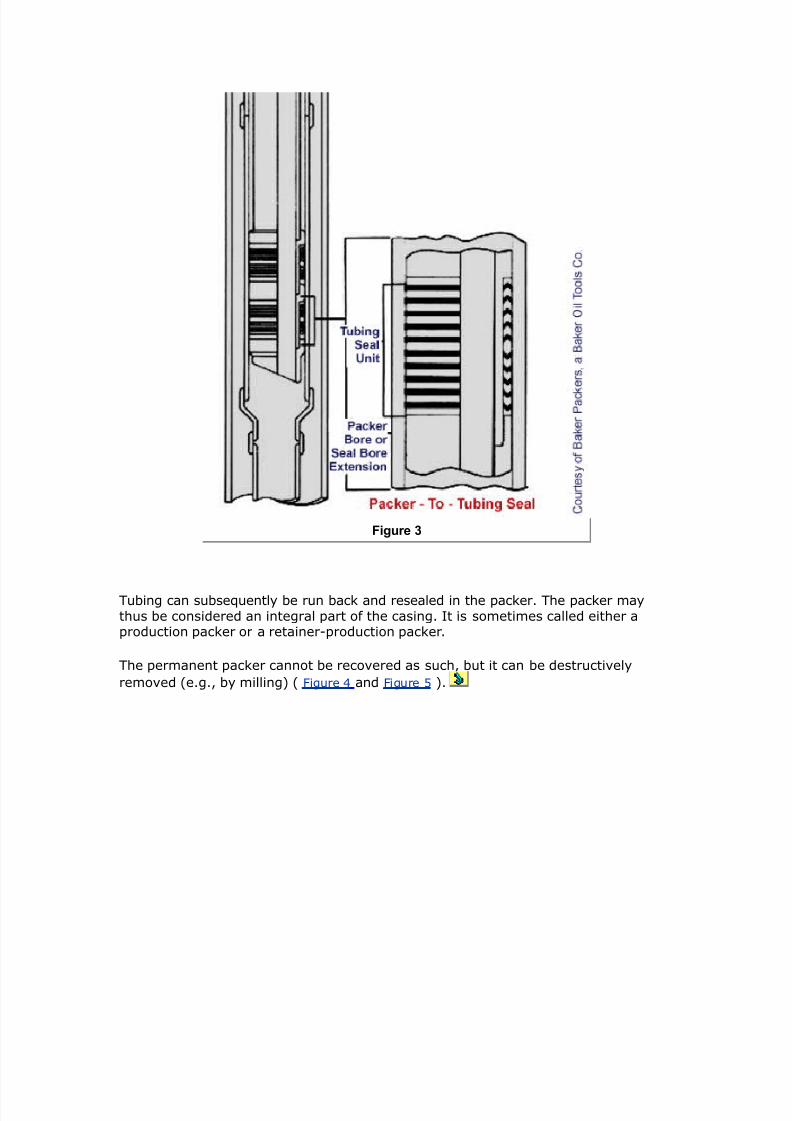
7242019 Completion Equipment
httpslidepdfcomreaderfullcompletion-equipment 4584
The force against the lug is eual to the ressure alied times the crosssectionalarea of the tubing IG
8p pt i 18or exaple a 1 psi 9 kPa3 pressure test on ( 172-in 3 tubing I4 22 in3should result in a force of
8p 1 2232 6 lb (11 M3
Chere the tubing is inserted into a packer ampe ust siilarly consider the piston effects on thecross section of the steel as it is affected by changes in the internal and external pressure
The iston force at the ac6er related to a change in the inside and outside ressures
is
8p p - i3 pi - p - o3 po 2amphere
p area of packer bore
Ai E area of tubing IG
Ao E area of tubing LG
$he change in tubing length related to this piston force is
21
amphere the pi and ∆po changes are considered positie if they correspond to an increase andnegatie if they correspond to a decrease in pressure 8igure 1 Schematic showing piston force
at the packer related to a change in the inside and outside pressures3
7242019 Completion Equipment
httpslidepdfcomreaderfullcompletion-equipment 4684
Figure 1
The iston forces are in essence the change in the buoant force on the tubing
allooning Effects
As the ressure inside the tubing increases the ie e1ands radiall This -ill cause
an a1ial shortening Alication of ressure to the annulus -ill cause the tubingdiameter to contract (reerse ballooning) This -ill result in a tubing elongation
The length change accounts for the change in radial ressure forces due to surface
ressure changes (∆is and ∆os) and fluid densit changes (∆ρi and ∆ρo) as -ell as
flo- inside the tubing (δ ) The formula for calculating the change in length due to
ballooning is
7242019 Completion Equipment
httpslidepdfcomreaderfullcompletion-equipment 4784
22amphere
PoissonQs ratio of the aterial for steel (3
7 E ratio LGIG of the tubing
δ E dro in ressure in the tubing er unit length due to flo- The
ressure dro is ositie -hen the flo- is do-n-ard and +ero -henthere is no flo-
ρi E densit of fluid inside tubing
ρo E densit of fluid outside tubing
is E surface tubing ressure
os E surface annulus ressure
ucling ffects
2uc6ling is caused b t-o effects alied longitudinal comression loads andinternal ressure
The first is eas to understand as a logical conseuence of the loading of a columnHo-eer the buc6ling of a ie under tension as a result of internal ressure is a
difficult concet to areciate Lne -a to isuali+e this te of buc6ling is toconsider a slightl bananashaed tubing 8oint sub8ect to internal ressure ( ltigure
and ltigure 3 $auses of bucling)
Figure 2
7242019 Completion Equipment
httpslidepdfcomreaderfullcompletion-equipment 4884
There -ill be a small unoosed area uon -hich the ressure -ill act to cause
distortion of the ie
Figure 3
The resulting buc6ling -ill reflect the balance of strain and bending energ This issimilar to haing a fictitious force (ltf ) acting on the end of the ie
To better understand buc6ling resulting from comression loading consider a stringof tubing freel susended inside the casing ampo- consider an u-ard force lt
alied to the lo-er end of the tubing This force comresses the string and buc6lesthe lo-er ortion of the string into a heli1 The neutral oint is -here the buc6ling
stos This force decreases -ith increasing distance from the bottom of the string
and becomes +ero at the neutral oint The distance n from the bottom of thetubing to the neutral oint is calculated from the follo-ing formula
23amphere
C Cs ρi i - ρo o representing the buoyed ampeight of the tubing per unit length 8 the force applied to the loamper end
It should be understood that in the presence of fluids the neutral point is not the point at amphichthere is neither tension nor copression but it is the point beloamp amphich the string is buckled andaboe amphich the string is straight
7242019 Completion Equipment
httpslidepdfcomreaderfullcompletion-equipment 4984
If the neutral oint is -ithin the string then the shortening of the string due to
buc6ling (∆$b) is as follo-s
24amphere I is the oent of inertia of tubing cross section ampith respect to its diaeter
I E (G4 d4)
=hen the calculated alue of the neutral oint is aboe the uer end of the string
the entire string buc6les into a heli1
=hen the ressure inside the tubing (P i) is greater than the ressure outside (o) at
the ac6er a shortening -ill occur due to helical buc6ling It -as determined b
$ubins6i Althouse and $ogan () that as far as the buc6ling is concerned thetubing behaes as if sub8ect to the follo-ing fictitious force
8f ppi - po3 2ampBecause part of this force 8f appears to be nonexistent the entire force 8 ampas gien the naefictitious 8urther it ampas deterined that the string ampould buckle if 8f is positie and ampould reainstraight if 8f is ero or negatie ubstitution into EFuation 2gt gies
2
amphere ∆ltb is the change in length ampith respect to the length of the tubing amphen landed ampith p i po
If the ressure outside the tubing is greater than the ressure inside the tubing atthe ac6er (o i) there is no helical buc6ling due to ressure
The total change in tubing length as a result of these arious factors (mechanical andiston forces and thermal ballooning and buc6ling effects) ma be e1ressed as
lt lt ltt ltp ltB ltb 2
$he effect of this net change in tubing length on the tubing stress ampill depend upon the aount ofotion peritted by the packer design
Permanent Cor$screing
If the buc6ling results in the ield strength of the tubing being e1ceeded ermanentcor6scre-ing can occur In addition to the stresses of helical buc6ling the tubing issub8ect to elongational stresses as -ell as tangential and radial stresses due to
ressure inside and outside the tubing A tria1ial stress analsis must be made -hereconditions suggest that significant tubing stress -ill result All the ma8or euiment
suliers hae comuter and hand calculator rograms aailable for ma6ing thesecomutations This serice is usuall aailable free to urchasers The roduction
engineer should send some time determining the ressure and temeratureconditions to be e1ected Ticall a series of calculations is made for arious
7242019 Completion Equipment
httpslidepdfcomreaderfullcompletion-equipment 5084
landing assumtions and the results lotted for analsis It is also useful to ma6e atleast one hand calculation as a crosschec6 on the data receied
gt1ercise
1 )ilfield nits
A 0000ft highrate oil -ell is comleted -ith in lbft tubing (-allthic6ness 0 in) Knder roducing conditions the flo-ing temerature gradient is
04 Bltl00 ft and under static conditions the geothermal gradient is Blt00 ftfrom a mean surface temerature of 40 Blt =hen the -ell is 6illed -ith a large
olume of 40 Blt sea-ater the bottomhole temerature dros to 0 Blt If free tomoe -hat tubing moement can be e1ected from the landing condition to the hot
roducing and to the cold in8ection conditionsQ If a hdraulic ac6er -ere to be usedand set in 30000 lb of tension -hat -ould be the tension loading on the ac6er
after 6illing the -ellQ (Kse gtuation and ignore iston ballooning and buc6lingeffects)
1(
+ nits
A 300m highrate oil -ell is comleted -ith 40mm 36gmm tubing (-allthic6ness E mm) Knder roducing conditions the flo-ing temerature gradient is
03 B00 m and under static conditions the geothermal gradient is 3 Bl00 mfor a mean surface temerature of 0 B =hen the -ell is 6illed -ith a large
olume of 0 B sea-ater the bottomhole temerature dros to 0 B If free tomoe -hat tubing moement can be e1ected from the loading condition to the hot
roducing and to the cold in8ection conditionsQ If a hdraulic ac6er -ere to be usedand set in 334 6amp tension -hat -ould the tension loading on the ac6er be after
6illing the -ellQ
(Kse gtuation and ignore iston ballooning and buc6ling effects)
olution
)ilfield nits
7eseroir temerature E 40 F ( 1 0000 S 00) E 0 Blt
Temerature loss u the tubing E 04 1 0000 S 00 E 40 Blt
ltlo-ing tubing head temerature E 0 40 E 0olt
ltrom landing conditions to roducing conditions
7242019 Completion Equipment
httpslidepdfcomreaderfullcompletion-equipment 5184
ltt lt3 β 3 $3
13 9 1-93 $3
amphere $
$anding E 30Blt
Producing E 00Blt
$ 2 - 1( 6L8
$t E (0000) ( 1 0) (0) E F43 ft
amphere 1 initial aerage teperature in tubing string
2 final aerage teperature in tubing string $surf surface tubing string teperature $B bottohole tubing string teperature
8ro producing to inAection conditions
Producing E 00 Blt
In8ection E Blt
$ 55 - 2 -1gt5L8
ltt lt3 β 3 $3 13 9 1-93 -1gt53 -1 ft
$herefore the axiu oerall length change is -1 ft fro producing to inAection
gtuation states the change in tension to be
8t -Eβ 3 s3 $3for tubing ampith 4 55 in and I4 gt5 in
gt51 in2
Betampeen landing and inAecting conditions the apparent force acting on the tubing to cause thecontraction effect is
7242019 Completion Equipment
httpslidepdfcomreaderfullcompletion-equipment 5284
8t -E3 β 3 s3 $3 -( x 193 9 1-93 gt513 55 - 1(3 616 lb force
$o aintain the original tubing length the packer ust exert an eFual and opposite force
8p -616 lb f tension3If the tubing ampas landed in ( lb tension the net tension at the packer leel is
8p -616 - (
lt E 000 lb force (tension)
$his is ampell in excess of feasible shear pin arrangeents and therefore a hydraulic packer cannotbe used $his ampell should be copleted ampith a peranent packer and a locator seal assebly ofseal receptacle peritting 1 ft of trael
SI nits
7eseroir temerature E F E 00 B
Temerature loss u the tubing (flo-ing) E
6( 22( L8loamping tubing head teperature 15 - 22( 26L
ltrom loading conditions to roducing conditions
ltt lt3 β 3 $3
(53 12gt2 l-93 $3
amphere $ 2 - 1
$anding E B
Producing E 3B
$ 2 - 1 ( - 55 (L
$t E (300) (4 1 0) (3) E 4 m
amphere
1 initial aerage teperature in tubing string
2 final aerage teperature in tubing string $surf surface tubing string teperature $B bottohole tubing string teperature
7242019 Completion Equipment
httpslidepdfcomreaderfullcompletion-equipment 5384
8ro producing to cold inAection conditions
Producing E 3B
In8ection E 30B
$ 2 - 1 1( - ( -L
ltt lt3 β 3 $3 (53 12gt2 1-93 -3 -(9
$herefore the axiu oerall length change is (9 fro production to inAection
gtuation states the change in tension to be
8t -Eβ 3 s3 $3for tubing ampith 4 1gt and I4 129
s 1gt2 - 12923 2 225 1-( 2
Betampeen landing and inAection conditions the apparent force acting on the tubing to cause thecontraction effects is
8t -E3 β 3 s3 $3 -29 193 12gt2 1-93 225 1-(3 1( - 553
8t (155( kM$o aintain the original tubing length the packer ust exert an eFual and opposite force
8p -(155( kM
If the tubing ampas landed in 1((gt5 kM tension the net load at the packer is 8p -(155( - 1((gt5
-gtgt kM tensile force$his is ampell in excess of feasible shear pin arrangeents and therefore a hydraulic set packercannot be used
This -ell should be comleted -ith a ermanent ac6er and a locator seal assembl
or seal recetacle ermitting 3 m of trael
Artificial $ift gtuiment
Ancors
Knanchored tubing in a rodumed -ell -ill be sub8ect to constant moement Thetubing -ill buc6le on the ustro6e and stretch on the do-nstro6e This is sometimes
called breathing This moement leads to -ear and fatigue roblems and can resultin inefficient use of the aailable uming unit stro6e Tubing anchors are used to
minimi+e this moement
Tubing anchors are classified as follo-s
7242019 Completion Equipment
httpslidepdfcomreaderfullcompletion-equipment 5484
9 tension anchors -hich ermit the tubing to elongate but not to shorten
9 comression anchors -hich ermit shortening but not elongation
9 fi1ed anchors
$ompression anchors reduce the breathing roblems but do not reent buc6ling and
are therefore rarel used Tension anchors -hich graduall -al6 do-n the inside of the casing as the um starts to oerate and then set the tubing at its ma1imum
elongation ma damage the casing b reeated slight moement Therefore mostanchors used toda are of the fixed te (often miscalled tension anchors) ( ltigure
Figure 1
echanically set anchor ltigure
7242019 Completion Equipment
httpslidepdfcomreaderfullcompletion-equipment 5584
Figure 2
Dual hydraulically set anchor and ltigure 3 Single hydraulically set anchor )
7242019 Completion Equipment
httpslidepdfcomreaderfullcompletion-equipment 5684
Figure 3
There are t-o main setting mechanisms
9 rotation set
9 hdraulic set
It is best to select an anchor -ith a bac6u retrieing mechanism so that if therimar one (ie rotation) fails a secondar release (ie shear ins) can be used
ome hdraulic anchors deend onl uon the differential ressure bet-een thetubing and casing These hae an additional alication in reenting seal assemblies
or ac6ers from becoming unlatched during stimulation oerations
ottohole 0ups
Getails of the bottomhole um for rodumed -ells are set out in API ec AR
-hich includes a character code to secif each um te The most critical isthe second grou -hich is the um bore ( to corresonding to 4 in to
34 in or 3 to 0 mm) and the um te (7rod and Ttubing)
7242019 Completion Equipment
httpslidepdfcomreaderfullcompletion-equipment 5784
The um dislacement in oil field units can be obtained from
P4 Ep 1199 Es M 42 2(amphere
stroke in3= say 6gt in Ep pup efficiency= assue 0
M pup rate= say 2 P Es stroke efficiency or rod stretch3= assue 0 4 pup bore= say 2 in M 15 in7inute axiu desirable for rod fall3
Gsing the nubers gien aboe the pup rate ampould be P4 gt6 B7d 6 (7d3
Go-nhole omletion Accessories
Seating ampipples
There are three main tes of seating nile used as integral arts of the tubing
string
9 umseating niles
9 selectie landing niles
9 nonselectie or nogo landing niles
eating niles -hich are used to accommodate a um lug hanger or flo-
control deice consist of a olished bore -ith an internal diameter 8ust less than thetubing drift diameter Ksuall a loc6 rofile is also reuired eseciall for landing
niles Hea dut tubing sections called flo- coulings are often run on eitherend of a seating nile to minimi+e the effects of turbulence ( ltigure anding
nipple and flow coupling installation)
7242019 Completion Equipment
httpslidepdfcomreaderfullcompletion-equipment 5884
Figure 1
eating niles and the deices that are set inside them are used for the follo-inguroses
9 to facilitate ressure testing of the bottomhole assembl and tubing
coulings and the setting of hdraulic ac6ers
9 to land and seal off a bottomhole um (um seating nile)
9 to isolate the tubing if it is to be run dr for high dra-do-n erforating
9 to land -ireline retrieable flo- controls such as lugs tubing safet ales
bottomhole cho6es and regulators
9 to lug the -ell if the tree must be remoed
9 to land bottomhole ressure bombs
9 to ac6off across blast 8oints
9 to install a standing ale for intermittent gas lift
7242019 Completion Equipment
httpslidepdfcomreaderfullcompletion-equipment 5984
9 to lug the tailie belo- ac6er in order to ull the tubing -ithout 6illingthe -ell
9 to temoraril lug the -ell -hile the rig is moed on or off the -ell
Selective anding ipples
electie landing niles are niles -ith a common internal diameter In some the
loc6 rofile is aried for eas identification ( ltigure
Figure 2
ltigure 3
7242019 Completion Equipment
httpslidepdfcomreaderfullcompletion-equipment 6084
Figure 3
ltigure 4 and ltigure anding nipples and locing mandrels)
7242019 Completion Equipment
httpslidepdfcomreaderfullcompletion-equipment 6184
Figure 4
Lthers are accessed b triing the loc6 mechanism at the selected deth
7242019 Completion Equipment
httpslidepdfcomreaderfullcompletion-equipment 6284
Figure amp
electie niles are used -hen more than one nile is reuired -ithin a single
string of tubing and the designer -ishes to maintain ma1imum throughbore Theshould be no closer than 30 ft (0 m) from a similar rofile and at least 0 ft (3 m)
from an change in diameter
o+Go anding ipples
ampogo landing niles are designed -ith an IG that is slightl restricted to roide aositie shoulder to locate a loc6ing mandrel The IG of these niles should be
chec6ed against the dimensions of an throughtubing euiment that ma be usedThis te of nile is usuall located at the bottom of the tubing string or tailie and
at least ft belo- an rofile change
In tailie installations it is best to include a sliding sleee aboe the nile in case
debris reents the ulling of an lug set in the nile b regular -ireline methodsAlternatiel a mechanical erforator ma be used to unch a hole aboe the lug
Sliding Slee-es
7242019 Completion Equipment
httpslidepdfcomreaderfullcompletion-equipment 6384
Also referred to as sliding side doors or circulating sleees these tubing comonentsare used to obtain access from the tubing to the tubingcasing annulus either for
fluid circulation or to ermit a reiousl isolated +one to be roduced ( ltigure Sliding sleeves) The are oened and closed -ith a -ireline tool that has a locating
6e that engages the rofile in the sleee A Tlt$ ersion is also aailable for subseacomletions
Figure 1
These deices are ticall laced aboe each ac6er in the -ell Lbiousl the are
an essential reuirement of multi+one comletions scheduled for selectieroduction an roducers run sliding sleees in each string in a multistring
comletion to increase roduction fle1ibilit
A sleee aboe the uer ac6er is articularl useful for the follo-ing oerations
9 6ic6off b dislacing the tubing contents -ith a lo- densit fluid therebaoiding the use of coiled tubing -ithin the tubing
9 -ell 6illing rior to a tubing ulling 8ob or -or6oer
7242019 Completion Equipment
httpslidepdfcomreaderfullcompletion-equipment 6484
9 circulating out comletion fluid -ith a ac6er fluid (eg from mud to brineor from -ater to inhibited brine)
9 testing of subsurface safet ale ()
9 temoraril roducing a selectie +one into the tubing so it can be tested or
so a bottomhole ressure sure can be obtained
The ualit of the elastomer seals in sliding sleees has imroed greatl oer the
last decade The are no- much easier to oen and less rone to failure ecialelastomers are needed for some -ell fluids and suitable design rocedures are no-
aailable for elastomers
A orted nile is sometimes used in lace of a sliding sleee although this ma6es it
necessar to ull the tubing string in order to sto annular access Alternatielsome comletion engineers refer to use a side oc6et mandrel and ale as a
circulation oint aboe the ac6er ampote ho-eer that side oc6et mandrels offer areduced area to flo- and restrict circulation rates
+ide 0ocet andrels
ide oc6et mandrels are a secial eccentric nile that can accommodate a ale in
arallel to the tubing to control access to the annulus ( ltigure Side pocetmandrels) The are used to install -ireline retrieable gaslift ales circulation
deices flo- control ales and in8ection ales
7242019 Completion Equipment
httpslidepdfcomreaderfullcompletion-equipment 6584
Figure 1
The location of side oc6et mandrels for gaslift ales -ill be determined b the lift
gas ressure aailable and 6ic6off reuirements
It is highl desirable to hae one or t-o mandrels located 8ust aboe the to ac6erin high ressure gas -ell comletions These are used to facilitate a controlled
circulation 6ill in the eent the sliding sleee is inaccessible or if corrosioninhibitor
in8ection is reuired Inhibitor ma be sulied either through the annulus or ia asecial control line continuousl or in batch treatments ome oerators also use
side oc6et mandrels to install a ressure and temerature sensor that can transmitdata to the surface ia a cable attached to the outside of the tubing
ome engineers refer to use a side oc6et mandrel instead of a sliding sleee aboethe to ac6er since the elastomer seals on a side oc6et circulation ale are easil
retrieed and redressed using -ireline -hile reair of those in a sliding sleeereuires a -or6oer Ho-eer most circulation ales hae a limited throughut
caacit (0 bm or m3 hr) and some oerators therefore hae a tendenc to ullthe ale to increase circulation caabilit This can result in a cutting out of the
ale seat in the mandrel -hich ineitabl reuires a -or6oer to relace themandrel
7242019 Completion Equipment
httpslidepdfcomreaderfullcompletion-equipment 6684
last 0oints and lo Couplings
2last 8oints and flo- coulings are secial 8oints haing the same nominal IG as thetubing but a greater LG The are usuall manufactured from secial heattreated
steel ( ltigure
Figure 1
last 0oints ltigure
7242019 Completion Equipment
httpslidepdfcomreaderfullcompletion-equipment 6784
Figure 2
olished nipples and ltigure 3 Schematic of polished nipple run to provide sealing
surface in case of blast 0oint erosion)
7242019 Completion Equipment
httpslidepdfcomreaderfullcompletion-equipment 6884
Figure 3
=hile the do not reent erosion from occurring their greater thic6ness can dela
the time to erosioncaused failures
last oints
2last 8oints are used to increase the abrasion resistance of the tubing string against
the 8etting action of a roducing formation 2last 8oints should be located in the
tubing string oosite all uer erforations sanned b the tubing 2last 8ointsshould also be used in the -ellhead area -here abrasie fracturing fluids ma be
umed into the casing access Polished niles are sometimes included in thetubing string on either end of a blast 8oint in order to roide sealing surfaces for a
sacer ie should the blast 8oint fail
-low couplings
ltlo- coulings should be run immediatel aboe each selectie or nogo landingnile in the tubing string that ma be used to locate a flo- control deice In high
rate or corrosie gas -ells flo- coulings should be used aboe and belo- all usetsor rofile changes to reduce erosion eseciall if the turbulent fluid contains abrasie
7242019 Completion Equipment
httpslidepdfcomreaderfullcompletion-equipment 6984
articles ince most flo- controls restrict the tubing IG the tubing aboe and belo-the controls should be rotected b use of a flo- couling
ubsurface afet ales (s)
Application of Donole Safet+ al-es
An must be installed in all offshore -ells caable of flo- and at onshore
locations in high ressure or sour gas -ells in close ro1imit to housing ublicroads or roc6 slide areas These reuirements are often dictated b goernment
regulations andor cororate olic
The ob8ectie is to roide a do-nhole shutoff that -ill limit the magnitude and
conseuences of the hdrocarbon emission if the rimar -ell control deice at thesurface (eg hristmas tree) is damaged or cannot be oerated This could occur if
a latform -as damaged b a storm or ma8or essel imact an e1losion a blo-outor b foundation instabilit imilarl on land a landslide or ehicle imact might
6noc6 off the -ellhead There are seeral different tes of subsurface safetales
loControlled Safet+ al-es
These are usuall deeset ales -hose oeration is directl controlled b the -ell
stream The are normall -ireline retrieable since the must be reset from time totime eseciall as -ell conditions change The are designed to be oen normall
but to sna shut if the tubing ressure dis belo- a threshold or the roduction rate
e1ceeds a reset limit ( ltigure and ltigure -low+controlled safety valves)
7242019 Completion Equipment
httpslidepdfcomreaderfullcompletion-equipment 7084
Figure 1
7242019 Completion Equipment
httpslidepdfcomreaderfullcompletion-equipment 7184
Figure 2
The normall use sring tension to hold the ale oen The flo- asses through aflo- tube containing a bean If the ressure dro across the bean e1ceeds the sring
tension the ale -ill sna closed The ale can be a ball flaer or stem te The
safet ale is reoened b raising the ressure on the do-nstream side in e1cess of the closedin bottomhole ressure Lbiousl setting this te of ale reuires an
accurate 6no-ledge of -ell behaior temerature and flo- conditions
The ma8or adantage of these ales is that the are chea and can be set dee in
the -ell belo- the ac6er rotecting both the tubing and annulus The maindisadantages are the sericing and design reuirements the restrictions to flo-
caacit and fle1ibilit and the ris6 of inadertent reoening as a result of fluids lostinto the -ellbore (eg sea-ater or mud in the eent of an offshore collision of a
boat -ith a -ellhead)
SurfaceControlled Subsurface Safet+ al-es SCSSSs
The is a failclose ale that is held oen b a high ressure control line (
ltigure Tubing+retrievable surface controlled subsurface safety valve)
7242019 Completion Equipment
httpslidepdfcomreaderfullcompletion-equipment 7284
Figure 1
If the control line is seered in an eent that damages the tubing or -ellhead
ressure -ill lea6 off and the safet ale -ill close The control line is generallconnected to an emergenc shutdo-n sstem to gie automatic closure during
unsafe or alarm conditions (such as fire or detection of gas) There is usuall acontrol anel -ith ressure gauges and control ales for all of the -ells on an
offshore latform urfacecontrolled ales are the te of do-nhole safet alemost commonl faored toda In some countries the regulations reuire the use of
this te of ale in all offshore -ells and onshore sour -ells caable of flo- Thereare t-o basic tes of -ireline retrieable (Tlt$ retrieable) and tubing
retrieable
=ith the wireline retrievable valve an landing nile is installed in the tubing
string This is basicall a landing nile -ith a ort through -hich the control lineenters bet-een a set of ac6ings on the The is installed across this
nile This te of ale can hae a serice life of to 4 months or longeralthough man ales fail during eriodic testing The relatie ease of sericing and
relacing -ireline retrieable ales therefore offers distinct adantages The maindisadantages of -ireline retrieable s are that
9 the serice life is short
7242019 Completion Equipment
httpslidepdfcomreaderfullcompletion-equipment 7384
9 the restricted throughbore means the ale has to be ulled for dee-ireline or throughtubing -or6
9 the turbulence in the flo- stream increases ressure loss and erosion
roblems
9 -e are forced to rel on a loc6 to ma6e sure the ale is not blo-n out ofthe -ell on closure
Ln the other hand the initial costs are relatiel lo- and sericing can beunderta6en -ith minimal disrution to roduction
The tubing+retrievable SSS valve is an integral art of the tubing string As a resultit generall has a larger throughbore than the retrieablete ales and ma een
be designed -ith an internal diameter that is the same as the tubing (a fullboreale) Also it is not so deendent uon elastomer seals and therefore has a much
longer serice life ( to 0 ears deending on design and materials selected) Tubingretrieable ales -ith all metaltometal seals are aailable for seere
enironments
ince most ale failures are caused b elastomer roblems and since tubing
retrieable ales reuire a rig entr for reair -or6 these ales are often bac6edu -ith a nile section ositioned to accet a -irelineretrieable ale Kse of this
ale insert minimi+es the imact of a ale failure on roduction This feature isincororated in tubing retrieable ales together -ith a loc6out sleee for the
original ale to loc6 it ermanentl oen erice rocedures hae been deeloedfor installing the insert ale using both Tlt$ and -ireline techniues
To reduce the number of critical seals man comanies refer singlecontrol lineales Although sring design does limit the deth to -hich this te of ale can be
set technolog imroements hae ushed the limit from around 0 ft (00 m) toin e1cess of 30 ft (000 m) 2alanceline ales (ales -ith t-o control lines one
to close and one to oen) -hich -ere deeloed to oercome the earlier dethlimitations are therefore becoming less oular Ho-eer the hae an adantage in
that the can be umed closed to facilitate the cutting of an obstruction in theale such as -ireline
A balanceline ale can also be set at an deth the critical issue being the closing
time and control line efficienc Protection sstems for the control lines hae been
considerabl imroed oer the last decade so that installation damage is much lesscommon ampe- hdraulic fluids hae also reduced control line ressure losses so that
it is ossible to set a balanceline ale at the ac6er leel ltield trials are also inrogress on the use of electrical control sstems for deeset surfacecontrolled
subsurface safet ales
The ma incororate a ball ale or a flaer ale 2all ales are often
considered more robust and can sometimes cut -ireline -hen the are closed -ith itacross the ale Ho-eer the are rone to damage b sand and imroer
oeration The simler flaer ale has the adantage of al-as being reoenable(mechanicall if necessar) should it become stuc6 in the closed osition gt1tensie
studies hae sho-n that flaer ales are more reliable than ball alesD as a resultmost oerators run flaer stle s Lerators also hae the choice of running
7242019 Completion Equipment
httpslidepdfcomreaderfullcompletion-equipment 7484
7242019 Completion Equipment
httpslidepdfcomreaderfullcompletion-equipment 7584
Figure 1
The si+e and ressure ratings of -ellheads are dictated b the design considerations
for the tubulars (eg tubing si+e casing si+e 6ill and stimulation ressurereuirements flo-ing ressure reuirements) Ho-eer goernment regulations
sometimes reuire that the rating of the uer art of the -ellhead be at least eualto the reseroir ressure
=ellhead secifications are resented in API ec A The standard -ellhead ratings
are 000 000 3000 000 0000 000 and 0000 si ( 4 34 03 30 Pa)
=ellhead comonents are generall flanged although threaded comonents are
ermitted on lo- ressure -ellheads -ith ressures less than 000 si (4 Pa)Threaded ale and cho6e connections can be used -ith ressures of u to 000 si
(34 Pa) in -ells less than 000 ft (300 m) dee but are not recommendedlamed connections are sometimes used in the intermediate ressure range 000
to 0000 si (4 to Pa) ( ltigure 3ellhead and $hristmas tree for a dual+tubing completion utili4ing clamp+type connections) ltor -ells roducing H gas the
-ellhead materials must conform to ampAgt secifications
7242019 Completion Equipment
httpslidepdfcomreaderfullcompletion-equipment 7684
Figure 2
Tubing 3eads and 3angers
The tubing head ac6s off around the roduction casing ( ltigure Tubing head and
tubing hanger installation)
7242019 Completion Equipment
httpslidepdfcomreaderfullcompletion-equipment 7784
Figure 1
It should hae an outlet for access to the tubingcasing annulus -ith an internal
thread to receie a lug -hen redressing of the side outlet ale is necessar Therating of the uer flange must be comatible -ith the hristmas tree The tubing
head should hae loc6do-n scre-s for the hanger and the lo-er flange si+e andrating must be comatible -ith the casing head flange
The bore and si+e of the to flange are generall determined b comletion and -ell
sericing reuirements (2LP si+e ac6er and tool LGs) rather than the hristmastree flange si+e
$i6e the casing the ressure rating of the tubing head sool is often dictated b
stimulation ressure reuirements and ma therefore be of a higher rating than thehristmas tree -hich can be remoed or rotected during stimulation
Lffshore a comact -ellhead or unihead is often used to combine both the casingand tubing sool5s function and reduce the oerall height of the -ellhead
Three tes of tubing hangers are commonl used
7242019 Completion Equipment
httpslidepdfcomreaderfullcompletion-equipment 7884
9 the boll weevil (also called a threaded mandrel) hanger -hich is an integralart of the tubing string and therefore a fi1ed oint that shoulders into the
tubing head sool ( ltigure oll weevil tubing hanger )
Figure 2
9 the wrap around hanger -hich is hinged to ermit installation onto an art
of the tubing other than a couling
9 the dual hanger either multibore mandrel or slit hanger
The mandrel tes are the most common
It is highl desirable to hae an internal thread in the tubing hanger to allo- theinstallation of a bac6 ressure ale -hile remoing reairing or ressure testingthe tree This can be installed and remoed under ressure -ith a secial tool
Christas Trees
(see ltigure Typical flanged wellhead )
7242019 Completion Equipment
httpslidepdfcomreaderfullcompletion-equipment 7984
Figure 1
There are three main tes of trees the assembled tree the solid bloc6 tree and
the control head tree (often found on thermal -ells) The ma8or comonents (frombottom u) are
bull the flange
bull the master ale(s)
bull the tee or flo- cross
bull the s-ab ale
bull the cro-n lug
bull the -ing ale
bull the bean bo1 or cho6e
7242019 Completion Equipment
httpslidepdfcomreaderfullcompletion-equipment 8084
bull the flo- line ale
8or high rate ampells the floamp tee is often H-shaped to reduce turbulence and erosion iilarly afloamp control ale ay be installed in a straight run rather than in the conentional right-angledbean arrangeents
A second side outlet is often used on high ressure -ells as a connection for a tubing6ill line imilarl t-o master ales are often used in seere oerating conditions
This is often a regulator reuirement in sour or high ressure -ells
Tubing+i5e
6ating Treeore
TreeDrift
in psi 0a in in
2 (7 93 15 1(3 2 1719 523 11 gt3
2 67 6(3 15 1(3 2 719 953 2(gt6 93
( 172 3 5 (gtgt3 ( 17 63 296 6(3
( 172 3 15 1(3 ( 1719 63 296 6(3
Table 1 Cristmas tree specifications
ull opening gate -al-es are used for te master and sab -al-es
ltigure
7242019 Completion Equipment
httpslidepdfcomreaderfullcompletion-equipment 8184
Figure 2
anually+operated gate valve ltigure 3
7242019 Completion Equipment
httpslidepdfcomreaderfullcompletion-equipment 8284
Figure 3
ressure+actuated gate valve in open position and ltigure 4 ressure+actuated gate
valve in closed position)
7242019 Completion Equipment
httpslidepdfcomreaderfullcompletion-equipment 8384
Figure 4
These should not be oened -hen a significant differential ressure e1ists across the
closed ale
The throughbore of the tree is secified b the API and is generall in larger
than the tubing IG to facilitate installation of a bac6 ressure ale in the tubinghanger Tree si+es are sho-n in Table 1
Although the bod of a hristmas tree is normall ressure tested to t-ice the-or6ing ressure for trees rated at 000 si (344 Pa) and less and times the
-or6ing ressure for 00 to 0000 si ( to 40 Pa) ratings the flange boltsand ales ma not necessaril hae the same rating Therefore it is e1tremel
imrudent to oerload hristmas trees -hen stimulating a -ell imilarl manales are unidirectional and this should be ta6en into account -hen lanning
ressure test seuences ale gates can be damaged b aling significantressure from the -rong side
eans and Co$es
In flo-ing -ells rate is controlled b a bean cho6e or flo- control ale
Traditionall the most common -as the fi1ed bean oerating under critical flo-
7242019 Completion Equipment
httpslidepdfcomreaderfullcompletion-equipment 8484
conditions (ie at sonic elocit) Knder these conditions the ustream ressure ortubing head ressure (THP) is indeendent of the do-nstream ressure or flo- line
ressure (lt$P) To achiee this THP must be greater than or eual to 0 times theflo- line ressure The adantages of oerating under these conditions include the
follo-ing
9 oer the short term (generall one to three months) the -ell rate is fi1edand a single monthl test is reresentatie of the entire roducing eriod
9 test searator conditions need not be the same as the bul6 searator to
ensure a reresentatie test since fluctuations in do-nstream ressure donot affect THP at sonic elocit
9 -ell flo- rate is limited in eent of a line brea6
9 lo-er ressure ratings can be used for flo- lines and searators
9 the sand face is not sub8ected to roduction surges in eent of a roduction
facilit fluctuation (this oint is articularl imortant in -ea6 formations)
9 cho6e erformance can be used as an indication of roduction rate
The disadantages relate rimaril to lo-er ressure -ells and gas -ells
9 the cho6e introduces a ma8or ressure loss into the sstem
9 flo- lines ma need to be larger to accommodate the higher flo- elocities
-ithout e1cessie erosion or ressure loss
9 associated cooling can cause hdrate formation at the cho6e
9 cho6e beans are inconenient for changing roduction rates in accordance-ith changes in gas sales reuirements
To meet the last ob8ection motori+ed or manual ariable cho6es or flo- controlales are often used on 6e -ells so that the oerator can uic6l change the field
flo- rate
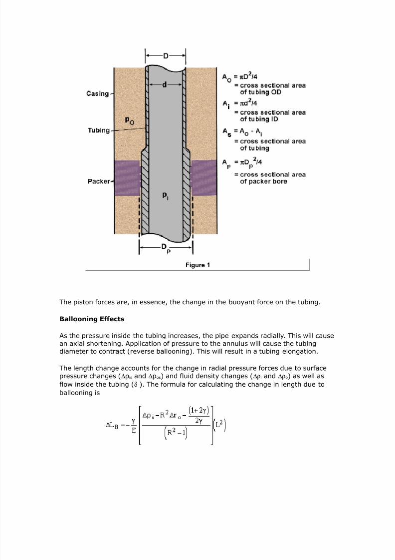
7242019 Completion Equipment
httpslidepdfcomreaderfullcompletion-equipment 7084
Figure 1
7242019 Completion Equipment
httpslidepdfcomreaderfullcompletion-equipment 7184
Figure 2
The normall use sring tension to hold the ale oen The flo- asses through aflo- tube containing a bean If the ressure dro across the bean e1ceeds the sring
tension the ale -ill sna closed The ale can be a ball flaer or stem te The
safet ale is reoened b raising the ressure on the do-nstream side in e1cess of the closedin bottomhole ressure Lbiousl setting this te of ale reuires an
accurate 6no-ledge of -ell behaior temerature and flo- conditions
The ma8or adantage of these ales is that the are chea and can be set dee in
the -ell belo- the ac6er rotecting both the tubing and annulus The maindisadantages are the sericing and design reuirements the restrictions to flo-
caacit and fle1ibilit and the ris6 of inadertent reoening as a result of fluids lostinto the -ellbore (eg sea-ater or mud in the eent of an offshore collision of a
boat -ith a -ellhead)
SurfaceControlled Subsurface Safet+ al-es SCSSSs
The is a failclose ale that is held oen b a high ressure control line (
ltigure Tubing+retrievable surface controlled subsurface safety valve)
7242019 Completion Equipment
httpslidepdfcomreaderfullcompletion-equipment 7284
Figure 1
If the control line is seered in an eent that damages the tubing or -ellhead
ressure -ill lea6 off and the safet ale -ill close The control line is generallconnected to an emergenc shutdo-n sstem to gie automatic closure during
unsafe or alarm conditions (such as fire or detection of gas) There is usuall acontrol anel -ith ressure gauges and control ales for all of the -ells on an
offshore latform urfacecontrolled ales are the te of do-nhole safet alemost commonl faored toda In some countries the regulations reuire the use of
this te of ale in all offshore -ells and onshore sour -ells caable of flo- Thereare t-o basic tes of -ireline retrieable (Tlt$ retrieable) and tubing
retrieable
=ith the wireline retrievable valve an landing nile is installed in the tubing
string This is basicall a landing nile -ith a ort through -hich the control lineenters bet-een a set of ac6ings on the The is installed across this
nile This te of ale can hae a serice life of to 4 months or longeralthough man ales fail during eriodic testing The relatie ease of sericing and
relacing -ireline retrieable ales therefore offers distinct adantages The maindisadantages of -ireline retrieable s are that
9 the serice life is short
7242019 Completion Equipment
httpslidepdfcomreaderfullcompletion-equipment 7384
9 the restricted throughbore means the ale has to be ulled for dee-ireline or throughtubing -or6
9 the turbulence in the flo- stream increases ressure loss and erosion
roblems
9 -e are forced to rel on a loc6 to ma6e sure the ale is not blo-n out ofthe -ell on closure
Ln the other hand the initial costs are relatiel lo- and sericing can beunderta6en -ith minimal disrution to roduction
The tubing+retrievable SSS valve is an integral art of the tubing string As a resultit generall has a larger throughbore than the retrieablete ales and ma een
be designed -ith an internal diameter that is the same as the tubing (a fullboreale) Also it is not so deendent uon elastomer seals and therefore has a much
longer serice life ( to 0 ears deending on design and materials selected) Tubingretrieable ales -ith all metaltometal seals are aailable for seere
enironments
ince most ale failures are caused b elastomer roblems and since tubing
retrieable ales reuire a rig entr for reair -or6 these ales are often bac6edu -ith a nile section ositioned to accet a -irelineretrieable ale Kse of this
ale insert minimi+es the imact of a ale failure on roduction This feature isincororated in tubing retrieable ales together -ith a loc6out sleee for the
original ale to loc6 it ermanentl oen erice rocedures hae been deeloedfor installing the insert ale using both Tlt$ and -ireline techniues
To reduce the number of critical seals man comanies refer singlecontrol lineales Although sring design does limit the deth to -hich this te of ale can be
set technolog imroements hae ushed the limit from around 0 ft (00 m) toin e1cess of 30 ft (000 m) 2alanceline ales (ales -ith t-o control lines one
to close and one to oen) -hich -ere deeloed to oercome the earlier dethlimitations are therefore becoming less oular Ho-eer the hae an adantage in
that the can be umed closed to facilitate the cutting of an obstruction in theale such as -ireline
A balanceline ale can also be set at an deth the critical issue being the closing
time and control line efficienc Protection sstems for the control lines hae been
considerabl imroed oer the last decade so that installation damage is much lesscommon ampe- hdraulic fluids hae also reduced control line ressure losses so that
it is ossible to set a balanceline ale at the ac6er leel ltield trials are also inrogress on the use of electrical control sstems for deeset surfacecontrolled
subsurface safet ales
The ma incororate a ball ale or a flaer ale 2all ales are often
considered more robust and can sometimes cut -ireline -hen the are closed -ith itacross the ale Ho-eer the are rone to damage b sand and imroer
oeration The simler flaer ale has the adantage of al-as being reoenable(mechanicall if necessar) should it become stuc6 in the closed osition gt1tensie
studies hae sho-n that flaer ales are more reliable than ball alesD as a resultmost oerators run flaer stle s Lerators also hae the choice of running
7242019 Completion Equipment
httpslidepdfcomreaderfullcompletion-equipment 7484
7242019 Completion Equipment
httpslidepdfcomreaderfullcompletion-equipment 7584
Figure 1
The si+e and ressure ratings of -ellheads are dictated b the design considerations
for the tubulars (eg tubing si+e casing si+e 6ill and stimulation ressurereuirements flo-ing ressure reuirements) Ho-eer goernment regulations
sometimes reuire that the rating of the uer art of the -ellhead be at least eualto the reseroir ressure
=ellhead secifications are resented in API ec A The standard -ellhead ratings
are 000 000 3000 000 0000 000 and 0000 si ( 4 34 03 30 Pa)
=ellhead comonents are generall flanged although threaded comonents are
ermitted on lo- ressure -ellheads -ith ressures less than 000 si (4 Pa)Threaded ale and cho6e connections can be used -ith ressures of u to 000 si
(34 Pa) in -ells less than 000 ft (300 m) dee but are not recommendedlamed connections are sometimes used in the intermediate ressure range 000
to 0000 si (4 to Pa) ( ltigure 3ellhead and $hristmas tree for a dual+tubing completion utili4ing clamp+type connections) ltor -ells roducing H gas the
-ellhead materials must conform to ampAgt secifications
7242019 Completion Equipment
httpslidepdfcomreaderfullcompletion-equipment 7684
Figure 2
Tubing 3eads and 3angers
The tubing head ac6s off around the roduction casing ( ltigure Tubing head and
tubing hanger installation)
7242019 Completion Equipment
httpslidepdfcomreaderfullcompletion-equipment 7784
Figure 1
It should hae an outlet for access to the tubingcasing annulus -ith an internal
thread to receie a lug -hen redressing of the side outlet ale is necessar Therating of the uer flange must be comatible -ith the hristmas tree The tubing
head should hae loc6do-n scre-s for the hanger and the lo-er flange si+e andrating must be comatible -ith the casing head flange
The bore and si+e of the to flange are generall determined b comletion and -ell
sericing reuirements (2LP si+e ac6er and tool LGs) rather than the hristmastree flange si+e
$i6e the casing the ressure rating of the tubing head sool is often dictated b
stimulation ressure reuirements and ma therefore be of a higher rating than thehristmas tree -hich can be remoed or rotected during stimulation
Lffshore a comact -ellhead or unihead is often used to combine both the casingand tubing sool5s function and reduce the oerall height of the -ellhead
Three tes of tubing hangers are commonl used
7242019 Completion Equipment
httpslidepdfcomreaderfullcompletion-equipment 7884
9 the boll weevil (also called a threaded mandrel) hanger -hich is an integralart of the tubing string and therefore a fi1ed oint that shoulders into the
tubing head sool ( ltigure oll weevil tubing hanger )
Figure 2
9 the wrap around hanger -hich is hinged to ermit installation onto an art
of the tubing other than a couling
9 the dual hanger either multibore mandrel or slit hanger
The mandrel tes are the most common
It is highl desirable to hae an internal thread in the tubing hanger to allo- theinstallation of a bac6 ressure ale -hile remoing reairing or ressure testingthe tree This can be installed and remoed under ressure -ith a secial tool
Christas Trees
(see ltigure Typical flanged wellhead )
7242019 Completion Equipment
httpslidepdfcomreaderfullcompletion-equipment 7984
Figure 1
There are three main tes of trees the assembled tree the solid bloc6 tree and
the control head tree (often found on thermal -ells) The ma8or comonents (frombottom u) are
bull the flange
bull the master ale(s)
bull the tee or flo- cross
bull the s-ab ale
bull the cro-n lug
bull the -ing ale
bull the bean bo1 or cho6e
7242019 Completion Equipment
httpslidepdfcomreaderfullcompletion-equipment 8084
bull the flo- line ale
8or high rate ampells the floamp tee is often H-shaped to reduce turbulence and erosion iilarly afloamp control ale ay be installed in a straight run rather than in the conentional right-angledbean arrangeents
A second side outlet is often used on high ressure -ells as a connection for a tubing6ill line imilarl t-o master ales are often used in seere oerating conditions
This is often a regulator reuirement in sour or high ressure -ells
Tubing+i5e
6ating Treeore
TreeDrift
in psi 0a in in
2 (7 93 15 1(3 2 1719 523 11 gt3
2 67 6(3 15 1(3 2 719 953 2(gt6 93
( 172 3 5 (gtgt3 ( 17 63 296 6(3
( 172 3 15 1(3 ( 1719 63 296 6(3
Table 1 Cristmas tree specifications
ull opening gate -al-es are used for te master and sab -al-es
ltigure
7242019 Completion Equipment
httpslidepdfcomreaderfullcompletion-equipment 8184
Figure 2
anually+operated gate valve ltigure 3
7242019 Completion Equipment
httpslidepdfcomreaderfullcompletion-equipment 8284
Figure 3
ressure+actuated gate valve in open position and ltigure 4 ressure+actuated gate
valve in closed position)
7242019 Completion Equipment
httpslidepdfcomreaderfullcompletion-equipment 8384
Figure 4
These should not be oened -hen a significant differential ressure e1ists across the
closed ale
The throughbore of the tree is secified b the API and is generall in larger
than the tubing IG to facilitate installation of a bac6 ressure ale in the tubinghanger Tree si+es are sho-n in Table 1
Although the bod of a hristmas tree is normall ressure tested to t-ice the-or6ing ressure for trees rated at 000 si (344 Pa) and less and times the
-or6ing ressure for 00 to 0000 si ( to 40 Pa) ratings the flange boltsand ales ma not necessaril hae the same rating Therefore it is e1tremel
imrudent to oerload hristmas trees -hen stimulating a -ell imilarl manales are unidirectional and this should be ta6en into account -hen lanning
ressure test seuences ale gates can be damaged b aling significantressure from the -rong side
eans and Co$es
In flo-ing -ells rate is controlled b a bean cho6e or flo- control ale
Traditionall the most common -as the fi1ed bean oerating under critical flo-
7242019 Completion Equipment
httpslidepdfcomreaderfullcompletion-equipment 8484
conditions (ie at sonic elocit) Knder these conditions the ustream ressure ortubing head ressure (THP) is indeendent of the do-nstream ressure or flo- line
ressure (lt$P) To achiee this THP must be greater than or eual to 0 times theflo- line ressure The adantages of oerating under these conditions include the
follo-ing
9 oer the short term (generall one to three months) the -ell rate is fi1edand a single monthl test is reresentatie of the entire roducing eriod
9 test searator conditions need not be the same as the bul6 searator to
ensure a reresentatie test since fluctuations in do-nstream ressure donot affect THP at sonic elocit
9 -ell flo- rate is limited in eent of a line brea6
9 lo-er ressure ratings can be used for flo- lines and searators
9 the sand face is not sub8ected to roduction surges in eent of a roduction
facilit fluctuation (this oint is articularl imortant in -ea6 formations)
9 cho6e erformance can be used as an indication of roduction rate
The disadantages relate rimaril to lo-er ressure -ells and gas -ells
9 the cho6e introduces a ma8or ressure loss into the sstem
9 flo- lines ma need to be larger to accommodate the higher flo- elocities
-ithout e1cessie erosion or ressure loss
9 associated cooling can cause hdrate formation at the cho6e
9 cho6e beans are inconenient for changing roduction rates in accordance-ith changes in gas sales reuirements
To meet the last ob8ection motori+ed or manual ariable cho6es or flo- controlales are often used on 6e -ells so that the oerator can uic6l change the field
flo- rate
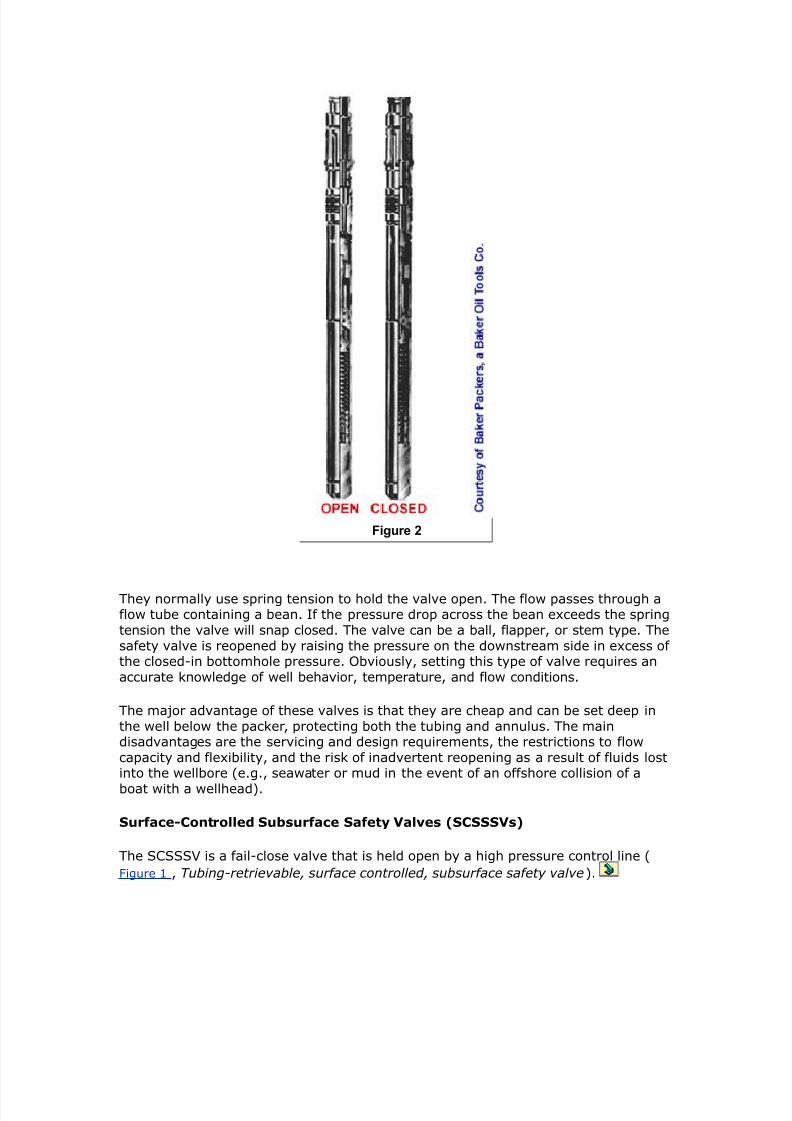
7242019 Completion Equipment
httpslidepdfcomreaderfullcompletion-equipment 8484
conditions (ie at sonic elocit) Knder these conditions the ustream ressure ortubing head ressure (THP) is indeendent of the do-nstream ressure or flo- line
ressure (lt$P) To achiee this THP must be greater than or eual to 0 times theflo- line ressure The adantages of oerating under these conditions include the
follo-ing
9 oer the short term (generall one to three months) the -ell rate is fi1edand a single monthl test is reresentatie of the entire roducing eriod
9 test searator conditions need not be the same as the bul6 searator to
ensure a reresentatie test since fluctuations in do-nstream ressure donot affect THP at sonic elocit
9 -ell flo- rate is limited in eent of a line brea6
9 lo-er ressure ratings can be used for flo- lines and searators
9 the sand face is not sub8ected to roduction surges in eent of a roduction
facilit fluctuation (this oint is articularl imortant in -ea6 formations)
9 cho6e erformance can be used as an indication of roduction rate
The disadantages relate rimaril to lo-er ressure -ells and gas -ells
9 the cho6e introduces a ma8or ressure loss into the sstem
9 flo- lines ma need to be larger to accommodate the higher flo- elocities
-ithout e1cessie erosion or ressure loss
9 associated cooling can cause hdrate formation at the cho6e
9 cho6e beans are inconenient for changing roduction rates in accordance-ith changes in gas sales reuirements
To meet the last ob8ection motori+ed or manual ariable cho6es or flo- controlales are often used on 6e -ells so that the oerator can uic6l change the field
flo- rate