completion fluids manual
TRANSCRIPT

COMPLETIONFLUIDS
Manual

TABLE OF CONTENTS
INTRODUCTION . . . . . . . . . . . . . . . . . . . . . . . . . . . . . . . . . iv
Chapter 1
DIVALENT BRINES . . . . . . . . . . . . . . . . . . . . . . . . . . . . . . 1·1• Calcium Chloride . . . . . . . . . . . . . . . . . . . . . . . . . . . . 1·1• Calcium Bromide. . . . . . . . . . . . . . . . . . . . . . . . . . . . 1·2• Calcium Chloride and Calcium Bromide . . . . 1·2• Calcium Chloride, Calcium Bromide,
Zinc Bromide . . . . . . . . . . . . . . . . . . . . . . . . . . . . . . . . 1·4• Blending Tables
U.S. . . . . . . . . . . . . . . . . . . . . . . . . . . . . . . . . . . . . . . . . . . 1·5Metric . . . . . . . . . . . . . . . . . . . . . . . . . . . . . . . . . . . . . . 1·23
Chapter 2
MONOVALENT BRINES. . . . . . . . . . . . . . . . . . . . . . . . . . 2·1• Sodium Chloride (Dry). . . . . . . . . . . . . . . . . . . . . . . 2·1• Potassium Chloride (Dry). . . . . . . . . . . . . . . . . . . . 2·1• Ammonium Chloride (Dry) . . . . . . . . . . . . . . . . . 2·1• Sodium Bromide (Liquid). . . . . . . . . . . . . . . . . . . . 2·1• Sodium Bromide (Dry) . . . . . . . . . . . . . . . . . . . . . . 2·2• Sodium Formate (Dry). . . . . . . . . . . . . . . . . . . . . . . 2·2• Potassium Formate (Liquid) . . . . . . . . . . . . . . . . . 2·2• Potassium Formate (Dry). . . . . . . . . . . . . . . . . . . . 2·2• Cesium Formate (Liquid) . . . . . . . . . . . . . . . . . . . . 2·3• Miscellaneous Blends . . . . . . . . . . . . . . . . . . . . . . . 2·3• Blending Tables
U.S. . . . . . . . . . . . . . . . . . . . . . . . . . . . . . . . . . . . . . . . . . . 2·4Metric . . . . . . . . . . . . . . . . . . . . . . . . . . . . . . . . . . . . . . 2·15
Chapter 3
EXAMPLE CALCULATIONS . . . . . . . . . . . . . . . . . . . . . . . 3·1
Chapter 4
QHSE . . . . . . . . . . . . . . . . . . . . . . . . . . . . . . . . . . . . . . . . . 4·1
Chapter 5
TEMPERATURE AND PRESSURE . . . . . . . . . . . . . . . . . . 5·1
ii
Chapter 6
TESTING PROCEDURES . . . . . . . . . . . . . . . . . . . . . . . . . . 6·1• RDF Testing Procedures . . . . . . . . . . . . . . . . . . . . 6·32
Chapter 7
DISPLACEMENT TECHNOLOGY . . . . . . . . . . . . . . . . . . 7·1
Chapter 8
VISCOSIFIERS AND FLUID-LOSS CONTROL. . . . . . . . 8·1
Chapter 9
CORROSION INHIBITION AND
PACKER FLUIDS . . . . . . . . . . . . . . . . . . . . . . . . . . . . . . . . 9·1
Chapter 10
FILTRATION . . . . . . . . . . . . . . . . . . . . . . . . . . . . . . . . . . 10·1
Chapter 11
SPEEDWELL* TOOLS . . . . . . . . . . . . . . . . . . . . . . . . . . . 11·1
Chapter 12
INTERVENTION FLUID SYSTEMS . . . . . . . . . . . . . . . 12·1
Chapter 13
RESERVOIR DRILL-IN FLUIDS . . . . . . . . . . . . . . . . . . 13·1
Chapter 14
ENGINEERING FORMULAS AND TABLES . . . . . . . . 14·1
Chapter 15
LIST OF PRODUCTS . . . . . . . . . . . . . . . . . . . . . . . . . . . . 15·1
iii

INTRODUCTION
M-I SWACO* provides a complete line of reser-voir drill-in, completion and workover fluidsand additives that help make oil and gas wellsmore productive. The company also offers fluidreclamation and filtration services comple-mented by a complete line of scrapers andbrushes for internal cleaning of casing, linersand risers.
This manual provides information and tech-nical data to support these systems and assistin their management during well design andfield operations.
iv

INTRODUCTION TO COMPLETION FLUIDS
With the recent proliferation of horizontalwellbores and open-hole completions, manydrilling and completion engineers now considerthe completion operation to begin as soon asthe drill bit enters the productive interval.Therefore, it is necessary to plan proceduresand implement practices to reduce formationdamage and maximize productivity at theearliest possible stage. Proper selection andapplication of the completion fluid is an inte-gral part of this process.
Completion fluid can be defined as any fluidpumped downhole to conduct operations afterthe initial drilling of a well. Workover fluids arethose used during remedial operations after awell has been completed and produced oil and/or gas. Clear, solids-free brine completion/workover fluids serve to control downhole for-mation pressures while reducing the risk ofpermanent formation damage (permeabilitydamage) resulting from solids invasion or someform of incompatibility between the comple-tion fluid and the in situ matrix. The clear brinesused for completion and workover applicationsare pure solutions of dissolved salt in water andmust be stable at surface and downhole con-ditions. Depending on the application, othercompletion/workover fluid types are some-times used, including solids-laden, oil-baseand emulsions. For the purpose of this docu-ment, no distinction is made between comple-tion and workover fluids and the terms are usedinterchangeably throughout. Packer fluids arethose that fill the annular volume above a pro-duction packer. The term reservoir drill-in fluidrefers to a drilling fluid designed specificallyfor the productive interval. Drill-in fluids are
v

INTRODUCTION TO COMPLETION FLUIDS
designed to minimize damage to the interval,typically by eliminating insoluble solids such asbarite, minimizing the total solids content andformulating such that a thin, resilient, remov-able, non-damaging filter cake is placed.
Among the typical operations in whichclear brines are applied are well kills, fishing,perforating, washing, drilling and gravel pack-ing and as packer fluids. In order to perform thedesired function, completion fluids must con-trol formation pressures, circulate and trans-port solids, protect the productive zone, bestable under surface and downhole conditions,be safely handled, be environmentally friendlyor used with controlled exposure, and be costeffective. Completion fluids have no purposewithin the formation and may in fact reducethe permeability. The operator has two choices:1) minimize fluid losses to the formation and2) use a formation-compatible fluid and acceptpartial losses.
Clear brine completion fluids are formulatedand applied in the field according to perform-ance specifications that ensure well controlwith minimal permeability reduction. Thesespecifications are not always expressly iden-tified but should always be understood andassigned. Density and solids content (expressedas clarity — NTU) are typical performancespecifications for clear brine, although selec-tion of a particular completion fluid accordingto these alone can be dangerous to the produc-tivity of a well. Proper density is necessary forpressure control.
Clarity is necessary to eliminate formationplugging by solids. In addition to these, the all-encompassing term “formation compatible” is
vi
INTRODUCTION TO COMPLETION FLUIDS
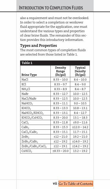
also a requirement and must not be overlooked.In order to select a completion or workoverfluid appropriate for the application, one mustunderstand the various types and propertiesof clear brine fluids. The remainder of this sec-tion provides this introductory information.
Types and PropertiesThe most common types of completion fluidsare selected from those listed in Table 1.
vii
Density Typical Range Density
Brine Type (lb/gal) (lb/gal)
NaCl 8.33 – 10.0 8.4 – 10.0
KCl 8.33 – 9.7 8.4 – 9.0
NH4Cl 8.33 – 8.9 8.4 – 8.7
NaBr 8.33 – 12.7 10.0 – 12.5
NaCl/NaBr 8.33 – 12.5 10.0 – 12.5
NaHCO2 8.33 – 11.1 9.0 – 10.5
KHCO2 8.33 – 13.3 10.8 – 13.1
NaHCO2/KHCO2 8.33 – 13.1 8.4 – 12.7
KHCO2/CsHCO2 8.33 – 20.0 13.1 – 18.3
CaCl2 8.33 – 11.8 ±9.0 – 11.6
CaBr2 8.33 – 15.3 ±12.0 – 14.2
CaCl2/CaBr2 8.33 – 15.1 11.7 – 15.1
ZnBr2 ±12 – 21.0 19.2 – 21.0
ZnBr2/CaBr2 ±12 – 19.2 ±14.0 – 19.2
ZnBr2/CaBr2/CaCl2 ±12 – 19.1 ±14.2 – 19.2
CsHCO2 ±8.33 – 20.0 13.2 – 19.2
Table 1

INTRODUCTION TO COMPLETION FLUIDS
Density and Blending The density of clear brine is obtained by dis-solving salt in water. The density achieved isdirectly related to the amount of salt in solu-tion. Table 2 shows the maximum solubilityof standard completion-fluid salts in water atroom temperature.
The data in Table 2 demonstrates that thesolubility of these salts in water is extremelyhigh, capable of producing densities up to21 lb/gal (2.52 SG). It is also evident that as thesolubility increases, the ratio of salt-to-water
viii
Sol Density Specific lb lbSalt wt % (lb/gal) Gravity Salt Water
Sodium 26 10.0 1.200 109 311Chloride
Potassium 24 9.7 1.164 98 309Chloride
Sodium 46 12.7 1.525 245 288Bromide
Calcium 40 11.8 1.416 198 298Chloride
Calcium 57 15.3 1.837 366 277Bromide
Zinc 78 21.0 2.521 688 194Bromide
Sodium 50 11.1 1.329 231 235Formate
Potassium 78 13.3 1.595 434 125Formate
Cesium 84 19.17 2.30 676.3 128.8Formate
Table 2: Maximum Solubility of Salt in Water
one bbl at room temperature

INTRODUCTION TO COMPLETION FLUIDS
becomes increasingly small. In fact, the satu-rated solutions of several of these systemscontain more salt than water. This fact isextremely important. It defines much of the“special chemistry” and properties of high-density completion fluids.
Commercial completion brines are oftenprepared with a combination of dry salts andliquid “stock fluids.” Some salts such as NaCland KCl are produced as dry material, i.e., theyare mined or formed through simple evapora-tion. Other brines like sodium bromide, potas-sium formate, calcium chloride and calciumbromide are manufactured as liquids. The drysalts are obtained only after processing theliquid. This process is energy consumptive andexpensive, so, solutions prepared with thesesalts are generally more expensive than theirall-liquid-blended counterparts. Zinc bromideis produced only in the liquid form. Table 3 listscommercially available “stock” fluids and drysalts. Comparing Tables 2 and 3 indicates thestock fluids are not produced as saturated solu-tions. In this way, the crystallization temper-ature is low enough as to allow storage inunheated tanks.
ix

INTRODUCTION TO COMPLETION FLUIDS
“Standard” brine tables follow that providethe necessary data to blend various clear brinefluids to a specific density. Simple blendingcalculations are also included. To blend fluidsto achieve a specific crystallization tempera-ture (see TCT) or, to blend to a lowest-costdensity, consult an M-I SWACO completionfluids representative.
x
Stock Fluids that are Manufactured as Liquids
11.6 lb/gal (1.39) [38%] CaCl2 (U.S.)
11.3 lb/gal (1.36) [35%] CaCl2 (Europe)
12.5 lb/gal (1.50) [45%] NaBr
14.2 lb/gal (1.70) [52%] CaBr2
13.1 lb/gal (1.57) [78%] KHCO2
19.2 lb/gal (2.30) [53% / 23%] ZnBr2 / CaBr2
18.3 lb/gal (2.20) Cesium Formate
20.5 lb/gal (2.46) ZnBr2
Fluids Prepared From Salts
10 lb/gal (1.20) NaCl Stock, 3 to 8% KCl, 3-8% NH4Cl
Stock Salts
NaCl, NaBr, KCl, NH4Cl, CaCl2, CaBr2, NaHCO2, KHCO2
Table 3
INTRODUCTION TO COMPLETION FLUIDS
xi
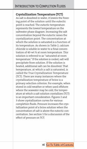
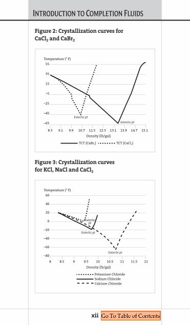
Crystallization Temperature (TCT)As salt is dissolved in water, it lowers the freez-ing point of the solution until the eutecticpoint is reached. The eutectic temperaturerepresents the lowest temperature on thesaltwater phase diagram. Increasing the saltconcentration beyond the eutectic raises thecrystallization point. The concentration atwhich the solution is saturated is a function ofits temperature. As shown in Table 2, calciumchloride is soluble in water to a final concen-tration of 40-wt % at room temperature. Thissolution is referred to as “saturated at roomtemperature.” If the solution is cooled, salt willprecipitate from solution. If the solution isheated, additional salt can be dissolved. Thattemperature, at which a salt is saturated, iscalled the True Crystallization Temperature(TCT). There are many instances where thecrystallization temperature of brine is aprimary selection criterion. For example, whenstored in cold weather or when used offshorewhere the seawater may be cold, the temper-ature at which a salt solution crystallizes (TCT)is an important consideration. Figures 2 and3 show crystallization curves for variouscompletion fluids. Pressure increases the crys-tallization point of a brine solution when theconcentration of salt is above the eutectic con-centration. See section 5 for a discussion of theeffect of pressure on TCT.
INTRODUCTION TO COMPLETION FLUIDS
xii
55
35
15
–5
–25
–45
–65
Temperature (° F)
Density (lb/gal)
8.3 9.1 9.9 10.7 11.5 12.3 13.1 13.9 14.7 15.1
Eutectic pt
Eutectic pt
TCT (CaBr2) TCT (CaCl2)
Figure 2: Crystallization curves for
CaCl2 and CaBr2
60
40
20
0
–20
–40
–60
–80
Density (lb/gal)
Potassium ChlorideSodium ChlorideCalcium Chloride
8.58 9.5 10 11 11.5 1210.59
Temperature (° F)
Eutectic pt
Eutectic pt
Eutecticpt
Figure 3: Crystallization curves
for KCl, NaCl and CaCl2

Chapter 1DIVALENT BRINES
COMPLETION FLUIDSMANUAL
1.D
IVALENTBRINES
DIVALENT BRINES
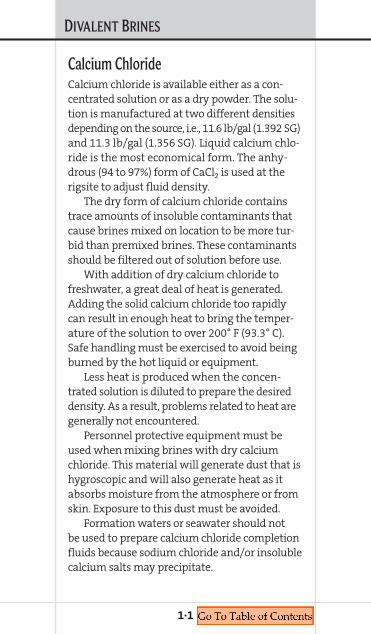
Calcium ChlorideCalcium chloride is available either as a con-centrated solution or as a dry powder. The solu-tion is manufactured at two different densitiesdepending on the source, i.e., 11.6 lb/gal (1.392 SG)and 11.3 lb/gal (1.356 SG). Liquid calcium chlo-ride is the most economical form. The anhy-drous (94 to 97%) form of CaCl2 is used at therigsite to adjust fluid density.
The dry form of calcium chloride containstrace amounts of insoluble contaminants thatcause brines mixed on location to be more tur-bid than premixed brines. These contaminantsshould be filtered out of solution before use.
With addition of dry calcium chloride tofreshwater, a great deal of heat is generated.Adding the solid calcium chloride too rapidlycan result in enough heat to bring the temper-ature of the solution to over 200° F (93.3° C).Safe handling must be exercised to avoid beingburned by the hot liquid or equipment.
Less heat is produced when the concen-trated solution is diluted to prepare the desireddensity. As a result, problems related to heat aregenerally not encountered.
Personnel protective equipment must beused when mixing brines with dry calciumchloride. This material will generate dust that ishygroscopic and will also generate heat as itabsorbs moisture from the atmosphere or fromskin. Exposure to this dust must be avoided.
Formation waters or seawater should notbe used to prepare calcium chloride completionfluids because sodium chloride and/or insolublecalcium salts may precipitate.
1·1
DIVALENT BRINES
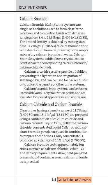
Calcium BromideCalcium Bromide (CaBr2) brine systems aresingle-salt solutions used to form clear-brineworkover and completion fluids with densitiesranging from 8.4 to 15.3 lb/gal (1.404 to 1.812 SG).The desired density is obtained by mixing stan-dard 14.2 lb/gal (1.704 SG) calcium bromide brinewith dry calcium bromide (or water) or by simplymixing dry calcium bromide in water. Calciumbromide systems exhibit lower crystallizationpoints than the corresponding calcium bromide/calcium chloride fluids.
Calcium bromide systems provide inhibition,preventing the hydration and migration ofswelling clays, and can be used for packer fluidsor to adjust the density of other brine systems.
Calcium bromide brine systems can be formu-lated with various crystallization points and areavailable for special applications and winter use.
Calcium Chloride and Calcium BromideClear brines having a density range of 11.7 lb/gal(1.404 SG) and 15.1 lb/gal (1.813 SG) are preparedusing a combination of calcium chloride andcalcium bromide. Liquid CaCl2, pelletized calciumchloride, concentrated liquid CaBr2, or solid cal-cium bromide powder are used in combinationto prepare these brines. CaBr2 concentrate isproduced at a density of 14.2 lb/gal (1.705 SG).
Calcium bromide costs approximately tentimes as much as calcium chloride. When TCTand density requirements allow, field-preparedbrines should contain as much calcium chlorideas is practical.
1·2

DIVALENT BRINES
1·3
Increasing the density of a CaCl2-CaBr2
blended brine by adding dry salts can causewellsite problems unless proper blending tech-niques are employed. For example, the additionof calcium bromide powder to a saturated blendcan result in the precipitation of calcium chlo-ride. Under these conditions, both water andcalcium bromide must be added to avoid precip-itation. An example of this is provided at theend of this section.
High-density, solids-free brines ranging upto 15.3 lb/gal (1.837 SG) can be prepared usingeither calcium bromide or the combination ofcalcium bromide and calcium chloride. The ratioof bromide-to-chloride in any particular densitydetermines the True Crystallization Temperature(TCT), or “freezing point.” Crystallization tem-perature must always be considered whenblending brines of any type, however, thechloride-bromide brines are particularly sensi-tive because small changes in the ratio of thetwo salts can result in significant changes inTCT. Environmental factors such as surface tem-perature, water depth and water temperatureand the influence of pressure on the crystal-lization point are important considerations andmust be taken into account when formulatingthe appropriate blend.
High-density slugs are used to ensure thata dry string is pulled when coming out of thehole. This is an important safety considerationsince calcium bromide brines can be irritatingto the skin and eyes.
When solid calcium bromide is added tofreshwater, considerable heat is released. Caremust be taken to avoid getting splashed by thehot liquid or burned by hot equipment. Unlike
DIVALENT BRINES
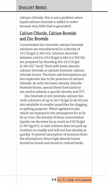
calcium chloride, this is not a problem whenliquid calcium bromide is added to waterbecause very little heat is generated.
Calcium Chloride, Calcium Bromide and Zinc BromideConcentrated zinc bromide-calcium bromidesolutions are manufactured to a density of19.2 lb/gal (2.305 SG). Solution densitiesbetween ±14.0 to 19.2 lb/gal (1.681 to 2.305 SG)are prepared by blending this 19.2 lb/gal(2.305 SG) “stock” fluid with lower densitycalcium bromide or calcium bromide-calciumchloride brines. The three-salt formulations areless expensive due to the presence of calciumchloride. As with the lower density chloride-bromide brines, special blend formulationsare used to achieve a specific density and TCT.
Zinc bromide or zinc bromide-calcium bro-mide solutions of up to 20.5 lb/gal (2.46 SG) arealso available in smaller quantities for sluggingor spiking purposes. When agitated in pitswhich are exposed to the atmosphere for as lit-tle as 4 hrs, the density of these concentratedliquids can decrease by as much as 0.02 lb/gal(2.397 kg/m3). A calm solution does not pick upmoisture as readily and will not lose density asquickly. To prevent absorption of moisture fromthe atmosphere, these high-density brinesshould be mixed and stored in covered tanks.
1·4

DIVALENT BRINES
1·5
Density CaCl2 Water CaCl2 Ca+2 Cl– TCT@70° F lb/bbl bbl/bbl wt % mg/L mg/L ° F
8.3 0.0 0.0000 0.00% 0 0 32
8.4 3.8 0.9989 1.00% 3,641 6,443 32
8.5 9.4 0.9951 2.50% 9,212 16,298 30
8.6 14.9 0.9914 3.90% 14,540 25,724 29
8.7 20.4 0.9875 5.30% 19,989 35,365 27
8.8 26.0 0.9836 6.70% 25,560 45,221 25
8.9 31.6 0.9796 8.00% 30,866 54,608 24
9.0 37.2 0.9755 9.40% 36,675 64,886 22
9.1 42.9 0.9714 10.70% 42,211 74,680 20
9.2 48.6 0.9671 11.90% 47,461 83,968 18
9.3 54.3 0.9627 13.20% 53,218 94,153 15
9.4 60.1 0.9583 14.50% 59,087 104,538 13
9.5 65.9 0.9537 15.70% 64,658 114,394 10
9.6 71.7 0.9491 16.90% 70,333 124,433 7
9.7 77.5 0.9443 18.10% 76,111 134,657 4
9.8 83.4 0.9395 19.30% 81,994 145,065 1
9.9 89.4 0.9346 20.40% 87,552 154,897 –3
10.0 95.3 0.9296 21.60% 93,638 165,666 –7
10.1 101.3 0.9245 22.70% 99,391 175,843 –12
10.2 107.3 0.9193 23.80% 105,239 186,190 –16
10.3 113.4 0.9140 24.90% 111,182 196,705 –22
10.4 119.4 0.9086 26.00% 117,221 207,389 –27
10.5 125.6 0.9031 27.00% 122,900 217,436 –33
10.6 131.7 0.8975 28.10% 129,125 228,450 –39
10.7 137.9 0.8918 29.10% 134,982 238,812 –46
10.8 144.1 0.8860 30.20% 141,394 250,155 –51
10.9 150.4 0.8801 31.20% 147,428 260,831 –36
Calcium Chloride CaCl2 (U.S.)
Mixing dry CaCl2 (94 to 97%) and water
Composition for one barrel fluid
Continues on next page

DIVALENT BRINES
1·6
Density CaCl2 Water CaCl2 Ca+2 Cl– TCT@70° F lb/bbl bbl/bbl wt % mg/L mg/L ° F
11.0 156.7 0.8741 32.20% 153,549 271,661 –22
11.1 163.0 0.8680 33.20% 159,757 282,644 –10
11.2 169.4 0.8618 34.20% 166,052 293,780 2
11.3 175.8 0.8555 35.20% 172,433 305,070 13
11.4 182.2 0.8491 36.10% 178,407 315,639 22
11.5 188.7 0.8426 37.10% 184,957 327,228 31
11.6 195.2 0.8360 38.10% 191,594 338,970 38
11.7 201.7 0.8293 39.00% 197,810 349,969 44
11.8 208.1 0.8227 39.90% 204,105 361,105 50
To calculate parts per million, divide mg/L by the specific gravity.
Continued from previous page
Calcium Chloride CaCl2 (U.S.)
Mixing dry CaCl2 (94 to 97%) and water
Composition for one barrel fluid

DIVALENT BRINES
1·7
CaCl2
Density 11.6 lb/gal Water TCT70° F bbl bbl ° F
8.3 0.022 0.978 32
8.4 0.022 0.978 32
8.5 0.052 0.948 30
8.6 0.083 0.917 29
8.7 0.113 0.887 27
8.8 0.144 0.856 25
8.9 0.174 0.826 24
9.0 0.203 0.797 22
9.1 0.233 0.767 20
9.2 0.264 0.736 18
9.3 0.294 0.706 15
9.4 0.325 0.675 13
9.5 0.356 0.644 10
9.6 0.390 0.610 7
9.7 0.420 0.580 4
9.8 0.450 0.550 1
9.9 0.480 0.520 –3
10.0 0.510 0.490 –7
10.1 0.540 0.460 –12
10.2 0.571 0.429 –16
10.3 0.601 0.399 –22
10.4 0.632 0.368 –27
10.5 0.663 0.337 –33
10.6 0.694 0.306 –39
10.7 0.724 0.276 –46
Calcium Chloride CaCl2 (U.S.)
Blending 11.6 lb/gal CaCl2 (liquid) and water
Composition for one barrel of fluid
Continues on next page

DIVALENT BRINES
1·8
CaCl2
Density 11.6 lb/gal Water TCT70° F bbl bbl ° F
10.8 0.755 0.245 –51
10.9 0.785 0.215 –36
11.0 0.820 0.180 –22
11.1 0.850 0.150 –10
11.2 0.880 0.120 2
11.3 0.910 0.090 13
11.4 0.940 0.060 22
11.5 0.970 0.030 31
11.6 1.000 0.000 38
Continued from previous page
Calcium Chloride CaCl2 (U.S.)
Blending 11.6 lb/gal CaCl2 (liquid) and water
Composition for one barrel of fluid

DIVALENT BRINES
1·9
Density CaBr2 Water CaBr2 Ca+2 Br– TCT@70° F lb/bbl bbl/bbl wt % mg/L mg/L ° F
8.33 0.0 1.0000 0.00% 0 0 32
8.4 3.6 0.9992 1.00% 2,022 8,062 30
8.5 9.0 0.9958 2.40% 4,910 19,580 30
8.6 14.4 0.9923 3.80% 7,866 31,366 29
8.7 19.9 0.9889 5.20% 10,889 43,421 28
8.8 25.3 0.9854 6.50% 13,768 54,900 27
8.9 30.7 0.9819 7.80% 16,709 66,628 27
9.0 36.1 0.9784 9.10% 19,713 78,606 26
9.1 41.6 0.9749 10.30% 22,560 89,961 25
9.2 47.0 0.9713 11.60% 25,687 102,428 24
9.3 52.4 0.9678 12.80% 28,653 114,253 23
9.4 57.9 0.9642 13.90% 31,449 125,405 22
9.5 63.3 0.9606 15.10% 34,528 137,681 21
9.6 68.8 0.9570 16.20% 37,433 149,266 19
9.7 74.3 0.9534 17.30% 40,391 161,061 18
9.8 79.7 0.9498 18.40% 43,402 173,068 17
9.9 85.2 0.9461 19.50% 46,466 185,286 16
10.0 90.7 0.9425 20.50% 49,343 196,756 14
10.1 96.2 0.9388 21.50% 52,267 208,417 13
10.2 102.0 0.9351 22.50% 55,240 220,270 11
10.3 107.0 0.9314 23.50% 58,261 232,316 10
10.4 113.0 0.9277 24.50% 61,329 244,553 8
10.5 118.0 0.9239 25.50% 64,447 256,982 7
10.6 124.0 0.9202 26.40% 67,357 268,586 5
10.7 129.0 0.9164 27.30% 70,310 280,362 3
10.8 135.0 0.9126 28.20% 73,307 292,312 2
10.9 140.0 0.9088 29.10% 76,347 304,434 0
11.0 146.0 0.9050 30.00% 79,430 316,729 –2
Calcium Bromide CaBr2 (U.S.)
Mixing dry CaBr2 (95%) and water
Composition for one barrel of fluid
Continues on next page
DIVALENT BRINES
1·10
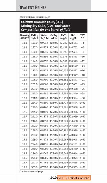
Density CaBr2 Water CaBr2 Ca+2 Br– TCT@70° F lb/bbl bbl/bbl wt % mg/L mg/L ° F
11.1 151.0 0.9012 30.80% 82,289 328,131 –4
11.2 157.0 0.8973 31.70% 85,457 340,762 –6
11.3 162.0 0.8935 32.50% 88,396 352,481 –8
11.4 168.0 0.8896 33.30% 91,373 364,353 –10
11.5 174.0 0.8857 34.10% 94,389 376,379 –12
11.6 179.0 0.8818 34.90% 97,444 388,559 –14
11.7 185.0 0.8779 35.70% 100,537 400,892 –16
11.8 190.0 0.8740 36.50% 103,668 413,379 –18
11.9 196.0 0.8700 37.20% 106,552 424,877 –21
12.0 201.0 0.8660 38.00% 109,758 437,661 –23
12.1 207.0 0.8621 38.70% 112,711 449,438 –25
12.2 213.0 0.8581 39.40% 115,698 461,349 –28
12.3 218.0 0.8540 40.10% 118,719 473,394 –30
12.4 224.0 0.8500 40.80% 121,773 485,574 ≤–30
12.5 229.0 0.8460 41.50% 124,861 497,888 ≤–30
12.6 235.0 0.8419 42.20% 127,983 510,336 ≤–30
12.7 241.0 0.8378 42.90% 131,139 522,919 ≤–30
12.8 246.0 0.8338 43.50% 134,020 534,408 ≤–30
12.9 252.0 0.8296 44.20% 137,240 547,249 ≤–30
13.0 258.0 0.8255 44.80% 140,182 558,978 ≤–30
13.1 263.0 0.8214 45.40% 143,152 570,822 ≤–30
13.2 269.0 0.8172 46.10% 146,469 584,048 ≤–30
13.3 274.0 0.8131 46.70% 149,499 596,131 ≤–30
13.4 280.0 0.8089 47.30% 152,558 608,330 ≤–30
13.5 286.0 0.8047 47.90% 155,646 620,644 ≤–30
13.6 291.0 0.8005 48.50% 158,763 633,073 ≤–30
13.7 297.0 0.7962 49.10% 161,909 645,618 ≤–30
13.8 303.0 0.7920 49.60% 164,752 656,953 ≤–30
Continued from previous page
Continues on next page
Calcium Bromide CaBr2 (U.S.)
Mixing dry CaBr2 (95%) and water
Composition for one barrel of fluid

DIVALENT BRINES
1·11
Density CaBr2 Water CaBr2 Ca+2 Br– TCT@70° F lb/bbl bbl/bbl wt % mg/L mg/L ° F
13.9 309.0 0.7877 50.20% 167,953 669,718 –29
14.0 314.0 0.7835 50.80% 171,183 682,598 –19
14.1 320.0 0.7792 51.30% 174,103 694,240 –10
14.2 326.0 0.7749 51.90% 177,389 707,341 –1
14.3 331.0 0.7705 52.40% 180,359 719,185 7
14.4 337.0 0.7662 52.90% 183,353 731,125 15
14.5 343.0 0.7618 53.50% 186,720 744,552 23
14.6 349.0 0.7575 54.00% 189,765 756,693 30
14.7 354.0 0.7531 54.50% 192,834 768,931 36
14.8 360.0 0.7487 55.00% 195,927 781,264 43
14.9 366.0 0.7443 55.50% 199,044 793,693 48
15.0 371.0 0.7398 56.00% 202,185 806,218 54
15.1 377.0 0.7354 56.50% 205,350 818,839 59
15.2 383.0 0.7309 57.00% 208,540 831,557 63
15.3 389.0 0.7264 57.50% 211,753 844,370 68
To calculate parts per million, divide mg/L by the specific gravity.
Continued from previous page
Calcium Bromide CaBr2 (U.S.)
Mixing dry CaBr2 (95%) and water
Composition for one barrel of fluid

DIVALENT BRINES
1·12
Density CaBr2
lb/gal 14.2 lb/gal Water TCT@70° F bbl/bbl bbl/bbl ° F
8.33 0.0 1.0000 32
8.4 0.012 0.989 30
8.5 0.028 0.972 30
8.6 0.045 0.957 29
8.7 0.061 0.940 28
8.8 0.078 0.924 27
8.9 0.094 0.908 27
9.0 0.111 0.892 26
9.1 0.127 0.876 25
9.2 0.144 0.859 24
9.3 0.162 0.840 23
9.4 0.177 0.826 22
9.5 0.194 0.810 21
9.6 0.211 0.793 19
9.7 0.228 0.777 18
9.8 0.244 0.760 17
9.9 0.261 0.744 16
10.0 0.278 0.727 14
10.1 0.295 0.710 13
10.2 0.312 0.693 11
10.3 0.329 0.676 10
10.4 0.345 0.660 8
10.5 0.362 0.643 7
10.6 0.379 0.626 5
10.7 0.396 0.609 3
10.8 0.413 0.592 2
10.9 0.430 0.575 0
Calcium Bromide CaBr2 (U.S.)
Blending 14.2 lb/gal CaBr2 (liquid) and water
Composition for one barrel
Continues on next page

DIVALENT BRINES
1·13
Density CaBr2
lb/gal 14.2 lb/gal Water TCT@70° F bbl/bbl bbl/bbl ° F
11.0 0.447 0.558 –2
11.1 0.464 0.541 –4
11.2 0.481 0.524 –6
11.3 0.499 0.507 –8
11.4 0.516 0.490 –10
11.5 0.533 0.472 –12
11.6 0.550 0.456 –14
11.7 0.567 0.438 –16
11.8 0.584 0.421 –18
11.9 0.601 0.403 –21
12.0 0.619 0.386 –23
12.1 0.636 0.369 –25
12.2 0.653 0.351 –28
12.3 0.670 0.334 –30
12.4 0.687 0.317 ≤–30
12.5 0.705 0.299 ≤–30
12.6 0.722 0.282 ≤–30
12.7 0.739 0.264 ≤–30
12.8 0.757 0.247 ≤–30
12.9 0.774 0.229 ≤–30
13.0 0.791 0.212 ≤–30
13.1 0.809 0.194 ≤–30
13.2 0.826 0.177 ≤–30
13.3 0.843 0.159 ≤–30
13.4 0.861 0.142 ≤–30
Calcium Bromide CaBr2 (U.S.)
Blending 14.2 lb/gal CaBr2 (liquid) and water
Composition for one barrel
Continued from previous page
Continues on next page

DIVALENT BRINES
1·14
Density CaBr2
lb/gal 14.2 lb/gal Water TCT@70° F bbl/bbl bbl/bbl ° F
13.5 0.878 0.124 ≤–30
13.6 0.895 0.106 ≤–30
13.7 0.913 0.089 ≤–30
13.8 0.930 0.071 ≤–30
13.9 0.948 0.053 –29
14.0 0.965 0.036 –19
14.1 0.982 0.018 –10
14.2 1.000 0.000 –1
Calcium Bromide CaBr2 (U.S.)
Blending 14.2 lb/gal CaBr2 (liquid) and water
Composition for one barrel
Continued from previous page

DIVALENT BRINES
1·15
Density CaBr2 CaCl2
lb/gal Water (95%) (94 – 97%) TCT@70° F bbl/bbl dry lb/bbl dry lb/bbl ° F
11.7 0.809 8.1 200.3 40
11.8 0.803 16.1 198.3 41
11.9 0.798 24.2 196.2 42
12.0 0.793 32.3 194.1 42
12.1 0.788 40.3 192.0 42
12.2 0.783 48.4 189.9 43
12.3 0.778 56.5 187.8 43
12.4 0.773 64.5 185.8 43
12.5 0.768 72.6 183.7 44
12.6 0.763 80.6 181.6 45
12.7 0.758 88.7 179.5 46
12.8 0.752 96.8 177.4 47
12.9 0.747 104.8 175.4 47
13.0 0.742 112.9 173.3 47
13.1 0.737 121.0 171.2 48
13.2 0.732 129.0 169.1 48
13.3 0.727 137.1 167.0 49
13.4 0.722 145.2 165.0 50
13.5 0.717 153.3 162.9 50
Calcium Bromide/Calcium Chloride
CaBr2/CaCl2 Dry (U.S.)
Mixing water, dry CaBr2 (95%) and
dry CaCl2 (94 to 97%)
Composition for one barrel
Continues on next page
DIVALENT BRINES
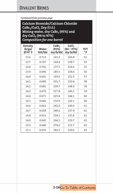
1·16
Density CaBr2 CaCl2
lb/gal Water (95%) (94 – 97%) TCT@70° F bbl/bbl dry lb/bbl dry lb/bbl ° F
13.6 0.712 161.3 160.8 52
13.7 0.707 169.4 158.7 53
13.8 0.701 177.5 156.6 55
13.9 0.696 185.5 154.6 56
14.0 0.691 193.6 152.5 57
14.1 0.686 201.7 150.4 58
14.2 0.681 209.7 148.3 58
14.3 0.676 217.8 146.2 59
14.4 0.671 225.8 144.1 60
14.5 0.666 233.9 142.1 60
14.6 0.661 242.0 140.0 61
14.7 0.658 249.2 137.9 61
14.8 0.651 258.1 135.8 61
14.9 0.645 266.2 133.7 62
15.0 0.640 274.2 131.7 62
15.1 0.635 282.3 129.6 63
Calcium Bromide/Calcium Chloride
CaBr2/CaCl2 Dry (U.S.)
Mixing water, dry CaBr2 (95%) and
dry CaCl2 (94 to 97%)
Composition for one barrel
Continued from previous page

DIVALENT BRINES
1·17
Density CaBr2 CaCl2 CaCl2
lb/gal 14.2 lb/gal 11.6 lb/gal dry TCT@70° F bbl/bbl bbl/bbl lb/bbl ° F
11.7 0.024 0.971 3.6 40
11.8 0.048 0.943 7.2 41
11.9 0.073 0.915 10.9 42
12.0 0.097 0.886 14.5 42
12.1 0.121 0.857 18.1 42
12.2 0.146 0.829 21.7 43
12.3 0.170 0.800 25.3 43
12.4 0.194 0.772 29.0 43
12.5 0.218 0.744 32.6 44
12.6 0.243 0.715 36.2 45
12.7 0.267 0.686 39.8 46
12.8 0.291 0.658 43.4 47
12.9 0.315 0.630 47.0 47
13.0 0.340 0.601 50.7 47
13.1 0.364 0.572 54.3 48
13.2 0.388 0.544 57.9 48
13.3 0.412 0.516 61.5 49
13.4 0.437 0.487 65.2 50
13.5 0.461 0.458 68.8 50
13.6 0.485 0.430 72.4 52
13.7 0.509 0.402 76.0 53
Calcium Bromide/Calcium Chloride
CaBr2/CaCl2 (U.S.)
Blending 14.2 lb/gal CaBr2 (liquid), 11.6 lb/gal
CaCl2 liquid and dry CaCl2 (94 to 97%)
Composition for one barrel
Continues on next page
DIVALENT BRINES
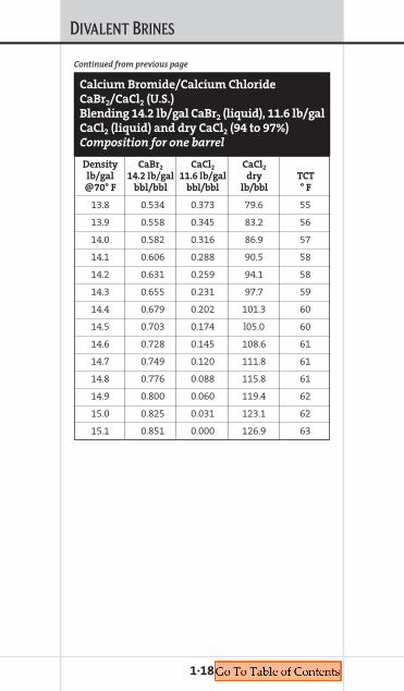
1·18
Density CaBr2 CaCl2 CaCl2
lb/gal 14.2 lb/gal 11.6 lb/gal dry TCT@70° F bbl/bbl bbl/bbl lb/bbl ° F
13.8 0.534 0.373 79.6 55
13.9 0.558 0.345 83.2 56
14.0 0.582 0.316 86.9 57
14.1 0.606 0.288 90.5 58
14.2 0.631 0.259 94.1 58
14.3 0.655 0.231 97.7 59
14.4 0.679 0.202 101.3 60
14.5 0.703 0.174 l05.0 60
14.6 0.728 0.145 108.6 61
14.7 0.749 0.120 111.8 61
14.8 0.776 0.088 115.8 61
14.9 0.800 0.060 119.4 62
15.0 0.825 0.031 123.1 62
15.1 0.851 0.000 126.9 63
Calcium Bromide/Calcium Chloride
CaBr2/CaCl2 (U.S.)
Blending 14.2 lb/gal CaBr2 (liquid), 11.6 lb/gal
CaCl2 (liquid) and dry CaCl2 (94 to 97%)
Composition for one barrel
Continued from previous page

DIVALENT BRINES
1·19
Density CaBr2 ZnCaBr2
lb/gal 14.2 lb/gal 19.2 lb/gal TCT@70° F bbl/bbl bbl/bbl ° F
14.2 1.000 0.000 –1
14.3 0.980 0.020 –5
14.4 0.960 0.040 –11
14.5 0.940 0.060 –17
14.6 0.920 0.080 –21
14.7 0.900 0.100 –27
14.8 0.880 0.120 –31
14.9 0.860 0.140 –34
15.0 0.840 0.160 –37
15.1 0.820 0.180 –40
15.2 0.800 0.200 –43
15.3 0.780 0.220 –46
15.4 0.760 0.240 –49
15.5 0.740 0.260 –52
15.6 0.720 0.280 –55
15.7 0.700 0.300 –58
15.8 0.680 0.320 –60
15.9 0.660 0.340 –62
16.0 0.640 0.360 –58
16.1 0.620 0.380 –55
16.2 0.600 0.400 –51
16.3 0.580 0.420 –46
16.4 0.560 0.440 –42
16.5 0.540 0.460 –37
16.6 0.520 0.480 –31
Calcium Bromide/Zinc Bromide
CaBr2/ZnBr2 (U.S.)
Blending 14.2 CaBr2 (liquid) with
19.2 ZnCaBr2 (liquid)
Composition for one barrel of fluid
Continues on next page

DIVALENT BRINES
1·20
Density CaBr2 ZnCaBr2
lb/gal 14.2 lb/gal 19.2 lb/gal TCT@70° F bbl/bbl bbl/bbl ° F
16.7 0.500 0.500 –27
16.8 0.480 0.520 –23
16.9 0.460 0.540 –20
17.0 0.440 0.560 –17
17.1 0.420 0.580 –14
17.2 0.400 0.600 –11
17.3 0.380 0.620 –9
17.4 0.360 0.640 –7
17.5 0.340 0.660 –5
17.6 0.320 0.680 –3
17.7 0.300 0.700 –2
17.8 0.280 0.720 –1
17.9 0.260 0.740 1
18.0 0.240 0.760 2
18.1 0.220 0.780 3
18.2 0.200 0.800 4
18.3 0.180 0.820 5
18.4 0.160 0.840 6
18.5 0.140 0.860 8
18.6 0.120 0.880 9
18.7 0.100 0.900 11
18.8 0.080 0.920 13
18.9 0.060 0.940 14
19.0 0.040 0.960 13
19.1 0.020 0.980 12
19.2 0.000 1.000 10
Continued from previous page
Calcium Bromide/Zinc Bromide
CaBr2/ZnBr2 (U.S.)
Blending 14.2 CaBr2 (liquid) with
19.2 ZnCaBr2 (liquid)
Composition for one barrel of fluid

DIVALENT BRINES
1·21
Density CaCl2/CaBr2 CaBr2/ZnCaBr2
lb/gal 15.1 lb/gal 19.2 lb/gal TCT@70° F bbl/bbl bbl/bbl ° F
15.1 1.000 0.000 62
15.2 0.976 0.024 60
15.3 0.951 0.049 59
15.4 0.927 0.073 58
15.5 0.903 0.098 56
15.6 0.878 0.122 55
15.7 0.854 0.146 54
15.8 0.829 0.171 53
15.9 0.805 0.195 51
16.0 0.780 0.220 51
16.1 0.756 0.244 49
16.2 0.732 0.268 48
16.3 0.707 0.293 47
16.4 0.683 0.317 46
16.5 0.658 0.342 44
16.6 0.634 0.366 42
16.7 0.610 0.390 39
16.8 0.585 0.415 34
16.9 0.561 0.439 28
17.0 0.537 0.463 25
17.1 0.512 0.488 26
17.2 0.488 0.512 28
17.3 0.463 0.537 28
17.4 0.439 0.561 30
17.5 0.415 0.585 32
Calcium Chloride/Calcium Bromide/
Zinc Bromide CaCl2/CaBr2/ZnBr2 (U.S.)
Blending 15.1 CaCl2/CaBr2 (liquid)
with 19.2 ZnCaBr2 (liquid)
Composition for one barrel of fluid
Continues on next page
DIVALENT BRINES
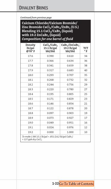
1·22
Density CaCl2/CaBr2 CaBr2/ZnCaBr2
lb/gal 15.1 lb/gal 19.2 lb/gal TCT@70° F bbl/bbl bbl/bbl ° F
17.6 0.390 0.610 34
17.7 0.366 0.634 36
17.8 0.341 0.659 38
17.9 0.317 0.683 40
18.0 0.293 0.707 35
18.1 0.268 0.732 32
18.2 0.244 0.756 29
18.3 0.220 0.780 27
18.4 0.195 0.805 25
18.5 0.171 0.829 23
18.6 0.146 0.854 21
18.7 0.122 0.878 20
18.8 0.097 0.903 19
18.9 0.073 0.927 17
19.0 0.049 0.951 16
19.1 0.024 0.976 12
19.2 0.000 1.000 10
To make 1 bbl 15.1 lb/gal = .851 (14.2 lb/gal CaBr2) + 127 ppb dry CaCl2.
Continued from previous page
Calcium Chloride/Calcium Bromide/
Zinc Bromide CaCl2/CaBr2/ZnBr2 (U.S.)
Blending 15.1 CaCl2/CaBr2 (liquid)
with 19.2 ZnCaBr2 (liquid)
Composition for one barrel of fluid
DIVALENT BRINES
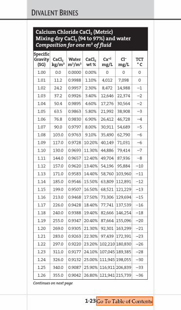
1·23
SpecificGravity CaCl2 Water CaCl2 Ca+2 Cl– TCT
(SG) kg/m3 m3/m3 wt % mg/L mg/L ° C
1.00 0.0 0.0000 0.00% 0 0 0
1.01 11.2 0.9988 1.10% 4,012 7,098 0
1.02 24.2 0.9957 2.30% 8,472 14,988 –1
1.03 37.2 0.9926 3.40% 12,646 22,374 –2
1.04 50.4 0.9895 4.60% 17,276 30,564 –2
1.05 63.5 0.9863 5.80% 21,992 38,908 –3
1.06 76.8 0.9830 6.90% 26,412 46,728 –4
1.07 90.0 0.9797 8.00% 30,911 54,689 –5
1.08 103.0 0.9763 9.10% 35,490 62,790 –6
1.09 117.0 0.9728 10.20% 40,149 71,031 –6
1.10 130.0 0.9693 11.30% 44,886 79,414 –7
1.11 144.0 0.9657 12.40% 49,704 87,936 –8
1.12 157.0 0.9620 13.40% 54,196 95,884 –10
1.13 171.0 0.9583 14.40% 58,760 103,960 –11
1.14 185.0 0.9546 15.50% 63,809 112,891 –12
1.15 199.0 0.9507 16.50% 68,521 121,229 –13
1.16 213.0 0.9468 17.50% 73,306 129,694 –15
1.17 226.0 0.9428 18.40% 77,741 137,539 –16
1.18 240.0 0.9388 19.40% 82,666 146,254 –18
1.19 255.0 0.9347 20.40% 87,664 155,096 –20
1.20 269.0 0.9305 21.30% 92,301 163,299 –21
1.21 283.0 0.9263 22.30% 97,439 172,391 –23
1.22 297.0 0.9220 23.20% 102,210 180,830 –26
1.23 311.0 0.9177 24.10% 107,045 189,385 –28
1.24 326.0 0.9132 25.00% 111,945 198,055 –30
1.25 340.0 0.9087 25.90% 116,911 206,839 –33
1.26 355.0 0.9042 26.80% 121,941 215,739 –36
Calcium Chloride CaCl2 (Metric)
Mixing dry CaCl2 (94 to 97%) and water
Composition for one m3 of fluid
Continues on next page

DIVALENT BRINES
1·24
SpecificGravity CaCl2 Water CaCl2 Ca+2 Cl– TCT
(SG) kg/m3 m3/m3 wt % mg/L mg/L ° C
1.27 369.0 0.8995 27.70% 127,036 224,754 –38
1.28 384.0 0.8948 28.60% 132,196 233,884 –41
1.29 399.0 0.8901 29.50% 137,422 243,128 –52
1.30 413.0 0.8852 30.30% 142,243 251,657 –45
1.31 428.0 0.8803 31.20% 147,594 261,126 –38
1.32 443.0 0.8754 32.00% 152,534 269,866 –32
1.33 458.0 0.8703 32.80% 157,532 278,708 –26
1.34 473.0 0.8652 33.70% 163,072 288,508 –20
1.35 488.0 0.8600 34.50% 168,189 297,561 –15
1.36 504.0 0.8548 35.30% 173,363 306,717 –10
1.37 519.0 0.8494 36.10% 178,596 315,974 –6
1.38 534.0 0.8440 36.90% 183,886 325,334 –2
1.39 550.0 0.8386 37.70% 189,234 334,796 2
1.40 565.0 0.8330 38.50% 194,640 344,360 5
1.41 581.0 0.8274 39.30% 200,104 354,026 8
1.42 596.0 0.8217 40.00% 205,113 362,887 10
To calculate parts per million, divide mg/L by the specific gravity.
Continued from previous page
Calcium Chloride CaCl2 (Metric)
Mixing dry CaCl2 (94 to 97%) and water
Composition for one m3 of fluid

DIVALENT BRINES
1·25
Specific CaCl2
Gravity 1.39 SG Water TCT(SG) m3/m3 m3/m3 ° C
1.00 0.000 1.000 0
1.01 0.022 0.978 –1
1.02 0.052 0.948 –1
1.03 0.083 0.917 –1
1.04 0.113 0.887 –2
1.06 0.144 0.856 –3
1.07 0.174 0.826 –4
1.08 0.203 0.797 –6
1.09 0.233 0.767 –7
1.10 0.264 0.736 –8
1.12 0.294 0.706 –9
1.13 0.325 0.675 –11
1.14 0.356 0.644 –12
1.15 0.390 0.610 –14
1.16 0.420 0.580 –16
1.18 0.450 0.550 –17
1.19 0.480 0.520 –19
1.20 0.510 0.490 –22
1.21 0.540 0.460 –24
1.22 0.571 0.429 –27
1.24 0.601 0.399 –30
1.25 0.632 0.368 –33
1.26 0.663 0.337 –36
1.27 0.694 0.306 –39
1.29 0.724 0.276 –43
Calcium Chloride CaCl2 (Metric)
Blending 1.39 SG CaCl2 (liquid) and water
Composition for one m3 of fluid
Continues on next page

DIVALENT BRINES
1·26
Specific CaCl2
Gravity 1.39 SG Water TCT(SG) m3/m3 m3/m3 ° C
1.30 0.755 0.245 –46
1.31 0.785 0.215 –38
1.32 0.820 0.180 –30
1.33 0.850 0.150 –23
1.35 0.880 0.120 –17
1.36 0.910 0.090 –11
1.37 0.940 0.060 –6
1.38 0.970 0.030 –1
1.39 1.000 0.000 3
Continued from previous page
Calcium Chloride CaCl2 (Metric)
Blending 1.39 SG CaCl2 (liquid) and water
Composition for one m3 of fluid
DIVALENT BRINES
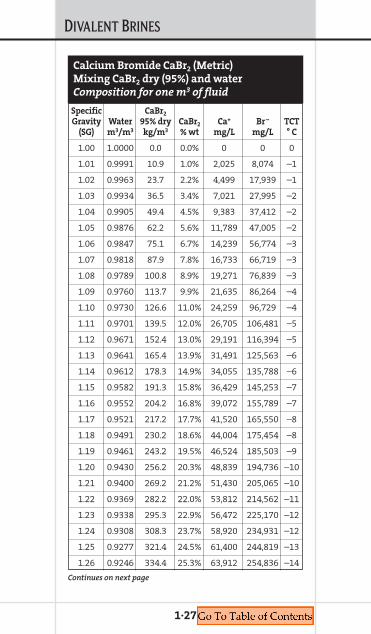
1·27
Specific CaBr2
Gravity Water 95% dry CaBr2 Ca+ Br– TCT(SG) m3/m3 kg/m3 % wt mg/L mg/L ° C
1.00 1.0000 0.0 0.0% 0 0 0
1.01 0.9991 10.9 1.0% 2,025 8,074 –1
1.02 0.9963 23.7 2.2% 4,499 17,939 –1
1.03 0.9934 36.5 3.4% 7,021 27,995 –2
1.04 0.9905 49.4 4.5% 9,383 37,412 –2
1.05 0.9876 62.2 5.6% 11,789 47,005 –2
1.06 0.9847 75.1 6.7% 14,239 56,774 –3
1.07 0.9818 87.9 7.8% 16,733 66,719 –3
1.08 0.9789 100.8 8.9% 19,271 76,839 –3
1.09 0.9760 113.7 9.9% 21,635 86,264 –4
1.10 0.9730 126.6 11.0% 24,259 96,729 –4
1.11 0.9701 139.5 12.0% 26,705 106,481 –5
1.12 0.9671 152.4 13.0% 29,191 116,394 –5
1.13 0.9641 165.4 13.9% 31,491 125,563 –6
1.14 0.9612 178.3 14.9% 34,055 135,788 –6
1.15 0.9582 191.3 15.8% 36,429 145,253 –7
1.16 0.9552 204.2 16.8% 39,072 155,789 –7
1.17 0.9521 217.2 17.7% 41,520 165,550 –8
1.18 0.9491 230.2 18.6% 44,004 175,454 –8
1.19 0.9461 243.2 19.5% 46,524 185,503 –9
1.20 0.9430 256.2 20.3% 48,839 194,736 –10
1.21 0.9400 269.2 21.2% 51,430 205,065 –10
1.22 0.9369 282.2 22.0% 53,812 214,562 –11
1.23 0.9338 295.3 22.9% 56,472 225,170 –12
1.24 0.9308 308.3 23.7% 58,920 234,931 –12
1.25 0.9277 321.4 24.5% 61,400 244,819 –13
1.26 0.9246 334.4 25.3% 63,912 254,836 –14
Calcium Bromide CaBr2 (Metric)
Mixing CaBr2 dry (95%) and water
Composition for one m3 of fluid
Continues on next page
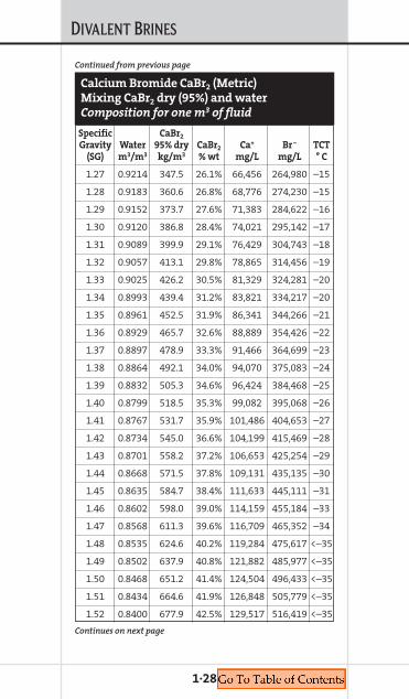
DIVALENT BRINES
1·28
Specific CaBr2
Gravity Water 95% dry CaBr2 Ca+ Br– TCT(SG) m3/m3 kg/m3 % wt mg/L mg/L ° C
1.27 0.9214 347.5 26.1% 66,456 264,980 –15
1.28 0.9183 360.6 26.8% 68,776 274,230 –15
1.29 0.9152 373.7 27.6% 71,383 284,622 –16
1.30 0.9120 386.8 28.4% 74,021 295,142 –17
1.31 0.9089 399.9 29.1% 76,429 304,743 –18
1.32 0.9057 413.1 29.8% 78,865 314,456 –19
1.33 0.9025 426.2 30.5% 81,329 324,281 –20
1.34 0.8993 439.4 31.2% 83,821 334,217 –20
1.35 0.8961 452.5 31.9% 86,341 344,266 –21
1.36 0.8929 465.7 32.6% 88,889 354,426 –22
1.37 0.8897 478.9 33.3% 91,466 364,699 –23
1.38 0.8864 492.1 34.0% 94,070 375,083 –24
1.39 0.8832 505.3 34.6% 96,424 384,468 –25
1.40 0.8799 518.5 35.3% 99,082 395,068 –26
1.41 0.8767 531.7 35.9% 101,486 404,653 –27
1.42 0.8734 545.0 36.6% 104,199 415,469 –28
1.43 0.8701 558.2 37.2% 106,653 425,254 –29
1.44 0.8668 571.5 37.8% 109,131 435,135 –30
1.45 0.8635 584.7 38.4% 111,633 445,111 –31
1.46 0.8602 598.0 39.0% 114,159 455,184 –33
1.47 0.8568 611.3 39.6% 116,709 465,352 –34
1.48 0.8535 624.6 40.2% 119,284 475,617 <–35
1.49 0.8502 637.9 40.8% 121,882 485,977 <–35
1.50 0.8468 651.2 41.4% 124,504 496,433 <–35
1.51 0.8434 664.6 41.9% 126,848 505,779 <–35
1.52 0.8400 677.9 42.5% 129,517 516,419 <–35
Calcium Bromide CaBr2 (Metric)
Mixing CaBr2 dry (95%) and water
Composition for one m3 of fluid
Continues on next page
Continued from previous page
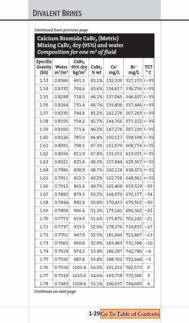
DIVALENT BRINES
1·29
Specific CaBr2
Gravity Water 95% dry CaBr2 Ca+ Br– TCT(SG) m3/m3 kg/m3 % wt mg/L mg/L ° C
1.53 0.8366 691.3 43.1% 132,209 527,155 <–35
1.54 0.8332 704.6 43.6% 134,617 536,756 <–35
1.55 0.8298 718.0 44.1% 137,045 546,437 <–35
1.56 0.8264 731.4 44.7% 139,806 557,444 <–35
1.57 0.8230 744.8 45.2% 142,276 567,293 <–35
1.58 0.8195 758.2 45.7% 144,766 577,222 <–35
1.59 0.8160 771.6 46.2% 147,276 587,230 <–35
1.60 0.8126 785.0 46.8% 150,127 598,598 <–35
1.61 0.8091 798.5 47.3% 152,679 608,774 <–35
1.62 0.8056 811.9 47.8% 155,252 619,031 <–35
1.63 0.8021 825.4 48.3% 157,844 629,367 <–35
1.64 0.7986 838.9 48.7% 160,128 638,473 <–35
1.65 0.7951 852.3 49.2% 162,758 648,961 <–35
1.66 0.7915 865.8 49.7% 165,408 659,529 –39
1.67 0.7880 879.3 50.2% 168,079 670,177 –34
1.68 0.7844 892.8 50.6% 170,433 679,562 –30
1.69 0.7809 906.4 51.1% 173,141 690,362 –25
1.70 0.7773 919.9 51.6% 175,870 701,242 –21
1.71 0.7737 933.5 52.0% 178,276 710,835 –17
1.72 0.7701 947.0 52.5% 181,043 721,867 –13
1.73 0.7665 960.6 52.9% 183,483 731,596 –10
1.74 0.7629 974.2 53.4% 186,287 742,780 –6
1.75 0.7592 987.8 53.8% 188,762 752,644 –3
1.76 0.7556 1001.4 54.2% 191,252 762,573 0
1.77 0.7519 1015.0 54.6% 193,758 772,566 3
1.78 0.7483 1028.6 55.1% 196,637 784,045 6
Calcium Bromide CaBr2 (Metric)
Mixing CaBr2 dry (95%) and water
Composition for one m3 of fluid
Continues on next page
Continued from previous page

DIVALENT BRINES
1·30
Specific CaBr2
Gravity Water 95% dry CaBr2 Ca+ Br– TCT(SG) m3/m3 kg/m3 % wt mg/L mg/L ° C
1.79 0.7446 1042.2 55.5% 199,177 794,174 9
1.80 0.7409 1055.9 55.9% 201,733 804,366 11
1.81 0.7372 1069.5 56.3% 204,306 814,623 14
1.82 0.7335 1083.2 56.7% 206,894 824,943 16
1.83 0.7298 1096.9 57.1% 209,498 835,327 18
1.84 0.7260 1110.5 57.5% 212,119 845,775 20
To calculate parts per million, divide mg/L by the specific gravity.
Calcium Bromide CaBr2 (Metric)
Mixing CaBr2 dry (95%) and water
Composition for one m3 of fluid
Continued from previous page
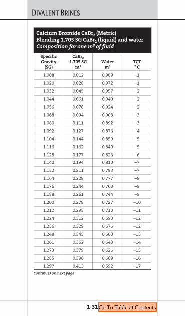
DIVALENT BRINES
1·31
Specific CaBr2
Gravity 1.705 SG Water TCT(SG) m3 m3 ° C
1.008 0.012 0.989 –1
1.020 0.028 0.972 –1
1.032 0.045 0.957 –2
1.044 0.061 0.940 –2
1.056 0.078 0.924 –2
1.068 0.094 0.908 –3
1.080 0.111 0.892 –3
1.092 0.127 0.876 –4
1.104 0.144 0.859 –5
1.116 0.162 0.840 –5
1.128 0.177 0.826 –6
1.140 0.194 0.810 –7
1.152 0.211 0.793 –7
1.164 0.228 0.777 –8
1.176 0.244 0.760 –9
1.188 0.261 0.744 –9
1.200 0.278 0.727 –10
1.212 0.295 0.710 –11
1.224 0.312 0.693 –12
1.236 0.329 0.676 –12
1.248 0.345 0.660 –13
1.261 0.362 0.643 –14
1.273 0.379 0.626 –15
1.285 0.396 0.609 –16
1.297 0.413 0.592 –17
Calcium Bromide CaBr2 (Metric)
Blending 1.705 SG CaBr2 (liquid) and water
Composition for one m3 of fluid
Continues on next page
DIVALENT BRINES
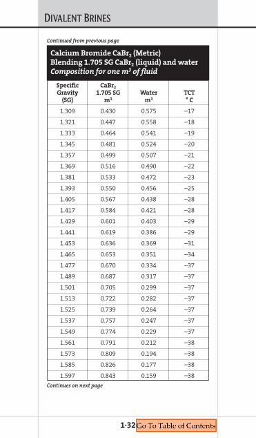
1·32
Specific CaBr2
Gravity 1.705 SG Water TCT(SG) m3 m3 ° C
1.309 0.430 0.575 –17
1.321 0.447 0.558 –18
1.333 0.464 0.541 –19
1.345 0.481 0.524 –20
1.357 0.499 0.507 –21
1.369 0.516 0.490 –22
1.381 0.533 0.472 –23
1.393 0.550 0.456 –25
1.405 0.567 0.438 –28
1.417 0.584 0.421 –28
1.429 0.601 0.403 –29
1.441 0.619 0.386 –29
1.453 0.636 0.369 –31
1.465 0.653 0.351 –34
1.477 0.670 0.334 –37
1.489 0.687 0.317 –37
1.501 0.705 0.299 –37
1.513 0.722 0.282 –37
1.525 0.739 0.264 –37
1.537 0.757 0.247 –37
1.549 0.774 0.229 –37
1.561 0.791 0.212 –38
1.573 0.809 0.194 –38
1.585 0.826 0.177 –38
1.597 0.843 0.159 –38
Calcium Bromide CaBr2 (Metric)
Blending 1.705 SG CaBr2 (liquid) and water
Composition for one m3 of fluid
Continues on next page
Continued from previous page
DIVALENT BRINES
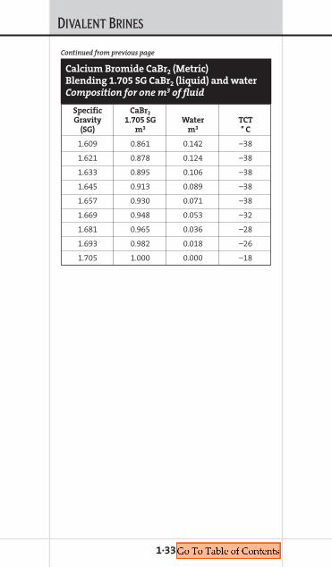
1·33
Specific CaBr2
Gravity 1.705 SG Water TCT(SG) m3 m3 ° C
1.609 0.861 0.142 –38
1.621 0.878 0.124 –38
1.633 0.895 0.106 –38
1.645 0.913 0.089 –38
1.657 0.930 0.071 –38
1.669 0.948 0.053 –32
1.681 0.965 0.036 –28
1.693 0.982 0.018 –26
1.705 1.000 0.000 –18
Calcium Bromide CaBr2 (Metric)
Blending 1.705 SG CaBr2 (liquid) and water
Composition for one m3 of fluid
Continued from previous page
DIVALENT BRINES
1·34
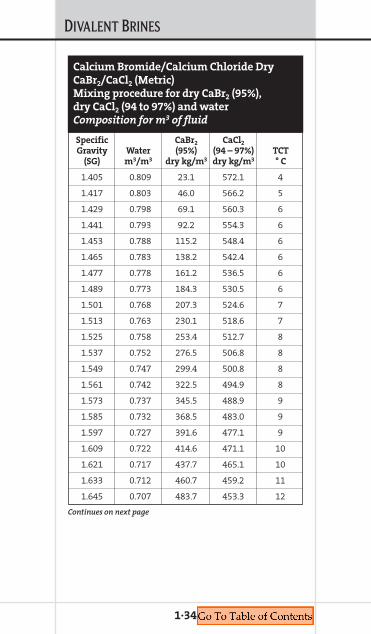
Specific CaBr2 CaCl2
Gravity Water (95%) (94 – 97%) TCT(SG) m3/m3 dry kg/m3 dry kg/m3 ° C
1.405 0.809 23.1 572.1 4
1.417 0.803 46.0 566.2 5
1.429 0.798 69.1 560.3 6
1.441 0.793 92.2 554.3 6
1.453 0.788 115.2 548.4 6
1.465 0.783 138.2 542.4 6
1.477 0.778 161.2 536.5 6
1.489 0.773 184.3 530.5 6
1.501 0.768 207.3 524.6 7
1.513 0.763 230.1 518.6 7
1.525 0.758 253.4 512.7 8
1.537 0.752 276.5 506.8 8
1.549 0.747 299.4 500.8 8
1.561 0.742 322.5 494.9 8
1.573 0.737 345.5 488.9 9
1.585 0.732 368.5 483.0 9
1.597 0.727 391.6 477.1 9
1.609 0.722 414.6 471.1 10
1.621 0.717 437.7 465.1 10
1.633 0.712 460.7 459.2 11
1.645 0.707 483.7 453.3 12
Calcium Bromide/Calcium Chloride Dry
CaBr2/CaCl2 (Metric)
Mixing procedure for dry CaBr2 (95%),
dry CaCl2 (94 to 97%) and water
Composition for m3 of fluid
Continues on next page

DIVALENT BRINES
1·35
Specific CaBr2 CaCl2
Gravity Water (95%) (94 – 97%) TCT(SG) m3/m3 dry kg/m3 dry kg/m3 ° C
1.657 0.701 506.8 447.3 13
1.669 0.696 529.8 441.4 13
1.681 0.691 552.8 435.5 14
1.693 0.686 575.9 429.5 14
1.705 0.681 599.0 423.5 14
1.717 0.676 622.0 417.6 15
1.729 0.671 645.0 411.7 16
1.741 0.666 668.0 405.7 16
1.753 0.661 691.0 399.8 16
1.765 0.658 711.8 393.8 16
1.777 0.651 737.2 387.9 16
1.789 0.645 760.2 381.9 17
1.801 0.640 783.2 376.0 17
1.813 0.635 806.2 370.1 17
Calcium Bromide/Calcium Chloride Dry
CaBr2/CaCl2 (Metric)
Mixing procedure for dry CaBr2 (95%),
dry CaCl2 (94 to 97%) and water
Composition for one m3 of fluid
Continued from previous page
DIVALENT BRINES
1·36
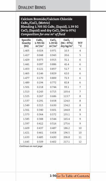
Specific CaBr2 CaCl2 CaCl2
Gravity 1.705 SG 1.39 SG (94 – 97%) TCT(SG) m3/m3 m3/m3 dry kg/m3 ° C
1.405 0.024 0.971 10.3 4
1.417 0.048 0.943 20.6 5
1.429 0.073 0.915 31.1 6
1.441 0.097 0.886 41.4 6
1.453 0.121 0.857 51.7 6
1.465 0.146 0.829 62.0 6
1.477 0.170 0.800 72.3 6
1.489 0.194 0.772 82.8 6
1.501 0.218 0.744 93.1 7
1.513 0.243 0.715 103.4 7
1.525 0.267 0.686 113.7 8
1.537 0.291 0.658 124.0 8
1.549 0.315 0.630 134.2 8
1.561 0.340 0.601 144.8 8
1.573 0.364 0.572 155.1 9
1.585 0.388 0.544 165.4 9
1.597 0.412 0.516 175.6 9
1.609 0.437 0.487 186.2 10
1.621 0.461 0.458 196.5 10
1.633 0.485 0.430 206.8 11
1.645 0.509 0.402 217.1 12
Calcium Bromide/Calcium Chloride
CaBr2/CaCl2 (Metric)
Blending 1.705 SG CaBr2 (liquid), 1.39 SG
CaCl2 (liquid) and dry CaCl2 (94 to 97%)
Composition for one m3 of fluid
Continues on next page

DIVALENT BRINES
1·37
Specific CaBr2 CaCl2 CaCl2
Gravity 1.705 SG 1.39 SG (94 – 97%) TCT(SG) m3/m3 m3/m3 dry kg/m3 ° C
1.657 0.534 0.373 227.3 13
1.669 0.558 0.345 237.6 13
1.681 0.582 0.316 248.2 14
1.693 0.606 0.288 258.5 14
1.705 0.631 0.259 268.7 14
1.717 0.655 0.231 279.0 15
1.729 0.679 0.202 289.3 16
1.741 0.703 0.174 299.9 16
1.753 0.728 0.145 310.2 16
1.765 0.749 0.120 319.3 16
1.777 0.776 0.088 330.7 16
1.789 0.800 0.060 341.0 17
1.801 0.825 0.031 351.6 17
1.813 0.851 0.000 362.4 17
Calcium Bromide/Calcium Chloride
CaBr2/CaCl2 (Metric)
Blending 1.705 SG CaBr2 (liquid), 1.39 SG
CaCl2 (liquid) and dry CaCl2 (94 to 97%)
Composition for one m3 of fluid
Continued from previous page
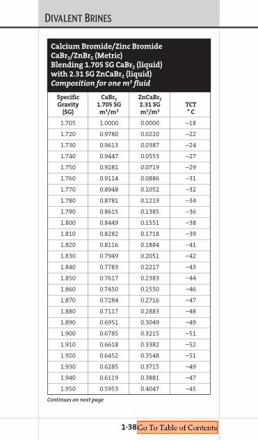
DIVALENT BRINES
1·38
Specific CaBr2 ZnCaBr2
Gravity 1.705 SG 2.31 SG TCT(SG) m3/m3 m3/m3 ° C
1.705 1.0000 0.0000 –18
1.720 0.9780 0.0220 –22
1.730 0.9613 0.0387 –24
1.740 0.9447 0.0553 –27
1.750 0.9281 0.0719 –29
1.760 0.9114 0.0886 –31
1.770 0.8948 0.1052 –32
1.780 0.8781 0.1219 –34
1.790 0.8615 0.1385 –36
1.800 0.8449 0.1551 –38
1.810 0.8282 0.1718 –39
1.820 0.8116 0.1884 –41
1.830 0.7949 0.2051 –42
1.840 0.7783 0.2217 –43
1.850 0.7617 0.2383 –44
1.860 0.7450 0.2550 –46
1.870 0.7284 0.2716 –47
1.880 0.7117 0.2883 –48
1.890 0.6951 0.3049 –49
1.900 0.6785 0.3215 –51
1.910 0.6618 0.3382 –52
1.920 0.6452 0.3548 –51
1.930 0.6285 0.3715 –49
1.940 0.6119 0.3881 –47
1.950 0.5953 0.4047 –45
Calcium Bromide/Zinc Bromide
CaBr2/ZnBr2 (Metric)
Blending 1.705 SG CaBr2 (liquid)
with 2.31 SG ZnCaBr2 (liquid)
Composition for one m3 fluid
Continues on next page
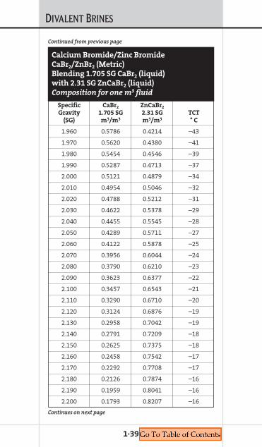
DIVALENT BRINES
1·39
Specific CaBr2 ZnCaBr2
Gravity 1.705 SG 2.31 SG TCT(SG) m3/m3 m3/m3 ° C
1.960 0.5786 0.4214 –43
1.970 0.5620 0.4380 –41
1.980 0.5454 0.4546 –39
1.990 0.5287 0.4713 –37
2.000 0.5121 0.4879 –34
2.010 0.4954 0.5046 –32
2.020 0.4788 0.5212 –31
2.030 0.4622 0.5378 –29
2.040 0.4455 0.5545 –28
2.050 0.4289 0.5711 –27
2.060 0.4122 0.5878 –25
2.070 0.3956 0.6044 –24
2.080 0.3790 0.6210 –23
2.090 0.3623 0.6377 –22
2.100 0.3457 0.6543 –21
2.110 0.3290 0.6710 –20
2.120 0.3124 0.6876 –19
2.130 0.2958 0.7042 –19
2.140 0.2791 0.7209 –18
2.150 0.2625 0.7375 –18
2.160 0.2458 0.7542 –17
2.170 0.2292 0.7708 –17
2.180 0.2126 0.7874 –16
2.190 0.1959 0.8041 –16
2.200 0.1793 0.8207 –16
Continues on next page
Continued from previous page
Calcium Bromide/Zinc Bromide
CaBr2/ZnBr2 (Metric)
Blending 1.705 SG CaBr2 (liquid)
with 2.31 SG ZnCaBr2 (liquid)
Composition for one m3 fluid
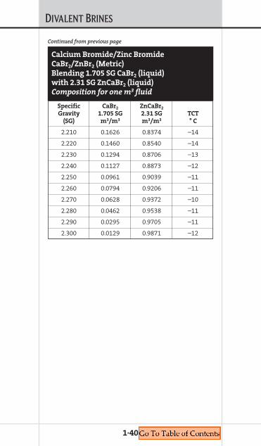
DIVALENT BRINES
1·40
Specific CaBr2 ZnCaBr2
Gravity 1.705 SG 2.31 SG TCT(SG) m3/m3 m3/m3 ° C
2.210 0.1626 0.8374 –14
2.220 0.1460 0.8540 –14
2.230 0.1294 0.8706 –13
2.240 0.1127 0.8873 –12
2.250 0.0961 0.9039 –11
2.260 0.0794 0.9206 –11
2.270 0.0628 0.9372 –10
2.280 0.0462 0.9538 –11
2.290 0.0295 0.9705 –11
2.300 0.0129 0.9871 –12
Continued from previous page
Calcium Bromide/Zinc Bromide
CaBr2/ZnBr2 (Metric)
Blending 1.705 SG CaBr2 (liquid)
with 2.31 SG ZnCaBr2 (liquid)
Composition for one m3 fluid
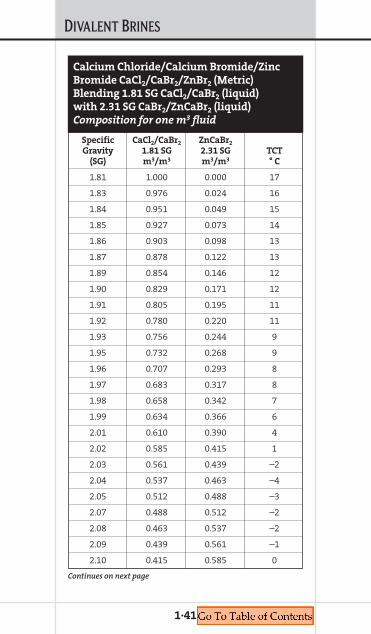
DIVALENT BRINES
1·41
Specific CaCl2/CaBr2 ZnCaBr2
Gravity 1.81 SG 2.31 SG TCT(SG) m3/m3 m3/m3 ° C
1.81 1.000 0.000 17
1.83 0.976 0.024 16
1.84 0.951 0.049 15
1.85 0.927 0.073 14
1.86 0.903 0.098 13
1.87 0.878 0.122 13
1.89 0.854 0.146 12
1.90 0.829 0.171 12
1.91 0.805 0.195 11
1.92 0.780 0.220 11
1.93 0.756 0.244 9
1.95 0.732 0.268 9
1.96 0.707 0.293 8
1.97 0.683 0.317 8
1.98 0.658 0.342 7
1.99 0.634 0.366 6
2.01 0.610 0.390 4
2.02 0.585 0.415 1
2.03 0.561 0.439 –2
2.04 0.537 0.463 –4
2.05 0.512 0.488 –3
2.07 0.488 0.512 –2
2.08 0.463 0.537 –2
2.09 0.439 0.561 –1
2.10 0.415 0.585 0
Calcium Chloride/Calcium Bromide/Zinc
Bromide CaCl2/CaBr2/ZnBr2 (Metric)
Blending 1.81 SG CaCl2/CaBr2 (liquid)
with 2.31 SG CaBr2/ZnCaBr2 (liquid)
Composition for one m3 fluid
Continues on next page
DIVALENT BRINES
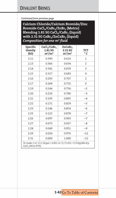
1·42
Specific CaCl2/CaBr2 ZnCaBr2
Gravity 1.81 SG 2.31 SG TCT(SG) m3/m3 m3/m3 ° C
2.11 0.390 0.610 1
2.13 0.366 0.634 2
2.14 0.341 0.659 3
2.15 0.317 0.683 4
2.16 0.293 0.707 2
2.17 0.268 0.732 0
2.19 0.244 0.756 –2
2.20 0.220 0.780 –3
2.21 0.195 0.805 –4
2.22 0.171 0.829 –5
2.23 0.146 0.854 –6
2.25 0.122 0.878 –7
2.26 0.097 0.903 –7
2.27 0.073 0.927 –8
2.28 0.049 0.951 –9
2.29 0.024 0.976 –11
2.31 0.000 1.000 –12
To make 1 m3 15.1 lb/gal = 0.851 m3 (1.71 SG) + 57.8 kg/bbl dryCaCl2 (94 to 97%).
Calcium Chloride/Calcium Bromide/Zinc
Bromide CaCl2/CaBr2/ZnBr2 (Metric)
Blending 1.81 SG CaCl2/CaBr2 (liquid)
with 2.31 SG CaBr2/ZnCaBr2 (liquid)
Composition for one m3 fluid
Continued from previous page
Chapter 2MONOVALENT BRINES
COMPLETION FLUIDSMANUAL
2.M
ONOVALENTBRINES

MONOVALENT BRINES
Sodium Chloride (Dry)Sodium Chloride (dry) is a high-purity salt usedin brines with a density range between 8.4 to10.0 lb/gal (1.008 to 1.200 SG). When mixedwith NaBr, densities up to 12.5 lb/gal (1.501 SG)can be achieved. It is packaged in 100-lb (45.4-kg),80-lb (36.3-kg), 110-lb (50-kg) sacks and 2,000-lb(909-kg) tote bags.
Potassium Chloride (Dry)Potassium Chloride (dry) is a high-purity saltthat can achieve brine densities from 8.4 lb/gal(1.008 SG) to 9.7 lb/gal (1.164 SG). It is packagedin 50-lb (22.7-kg), 100-lb (45.4-kg) sacks and2,000-lb (909-kg) tote bags.
Ammonium Chloride (Dry)Ammonium Chloride (dry) is a high-purity saltthat can generate brine densities from 8.4 to9.7 lb/gal (1.008 to 1.164 SG). It is also used at 2to 4% as a clay and shale stabilizer. It may liber-ate ammonia gas at pHs above 9.0. Ammoniumchloride (dry) is packaged in 50-lb (22.7-kg) and55-lb (25-kg) sacks.
Sodium Bromide (Liquid) Sodium Bromide (liquid) is a single-salt clearbrine fluid. Pure sodium bromide solutions canbe prepared with densities between 8.4 lb/gal(1.008 SG) and 12.8 lb/gal (1.537 SG). Typically,it can be mixed with NaCl to prepare brineswith densities between 10.0 and 12.5 lb/gal(1.200 and 1.501 SG). It is used where formationwaters contain high concentrations of bicar-bonate or sulfate ions. It can be formulated for
2·1

MONOVALENT BRINES
various crystallization temperatures and forsummer or winter blends. It is packaged inbulk-liquid quantities.
Sodium Bromide (Dry) Sodium Bromide (dry) is a high-purity salt.Pure sodium bromide solutions can be preparedwith densities between 8.4 lb/gal (1.008 SG) and12.8 lb/gal (1.537 SG). Typically, it can be mixedwith NaCl to prepare brines with densitiesbetween 8.4 and 12.5 lb/gal (1.008 and 1.501 SG).It is used where formation waters contain highconcentrations of bicarbonate or sulfate ionsand is packaged in 55-lb (25-kg) sacks.
Sodium Formate (Dry)Sodium formate (dry) is a high-purity, organicsalt that can deliver brine fluid densities rang-ing from 8.4 lb/gal (1.008 SG) to 11.1 lb/gal(1.330 SG). It is packaged in 55-lb (25-kg) sacksand 2,205-lb (1,000-kg) “big” bags.
Potassium Formate (Liquid) Potassium Formate (liquid) is a single-saltclear brine fluid. Pure potassium formate solu-tions can be prepared with densities between8.4 lb/gal (1.08 SG) and 13.1 lb/gal (1.571 SG).Potassium formate provides excellent thermalstabilization effects on natural polymers. Thepotassium ion provides excellent clay stabili-zation and swelling inhibition of shales.
Potassium Formate (Dry) Potassium formate (dry) is a high-purity,organic salt with eventual densities between
2·2
MONOVALENT BRINES
8.4 lb/gal (1.008 SG) and 13.1 lb/gal (1.573 SG).It is packaged in 55-lb (25-kg) sacks or in 2,205-lb(1,000-kg) “big” bags.
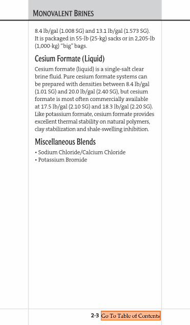
Cesium Formate (Liquid)Cesium formate (liquid) is a single-salt clearbrine fluid. Pure cesium formate systems canbe prepared with densities between 8.4 lb/gal(1.01 SG) and 20.0 lb/gal (2.40 SG), but cesiumformate is most often commercially availableat 17.5 lb/gal (2.10 SG) and 18.3 lb/gal (2.20 SG).Like potassium formate, cesium formate providesexcellent thermal stability on natural polymers,clay stabilization and shale-swelling inhibition.
Miscellaneous Blends• Sodium Chloride/Calcium Chloride• Potassium Bromide
2·3

MONOVALENT BRINES
2·4
Densitylb/gal NaCl Water NaCl Na+ Cl– TCT@70° F lb/bbl bbl/bbl wt % mg/L mg/L ° F
8.33 0.0 1.000 0.0 0 0 32
8.40 3.7 0.998 1.0 4,133 6,350 31
8.50 9.6 0.993 2.7 10,710 16,524 29
8.60 16.2 0.986 4.4 18,060 27,761 27
8.70 22.2 0.981 6.0 24,638 38,106 25
8.80 28.1 0.976 7.5 31,258 48,259 23
8.90 34.8 0.969 9.2 38,662 59,701 21
9.00 41.0 0.962 10.7 45,576 70,200 19
9.10 47.7 0.955 12.4 53,071 81,900 16
9.20 54.3 0.948 13.9 60,389 93,178 14
9.30 61.3 0.940 15.5 68,188 105,239 11
9.40 68.0 0.933 17.1 75,576 116,748 8
9.50 74.6 0.926 18.5 82,992 128,022 5
9.60 81.3 0.919 20.0 90,432 139,507 1
9.70 88.6 0.910 21.5 98,474 152,135 –2
9.80 95.6 0.902 23.0 106,310 164,052 –6
9.90 102.3 0.895 24.4 113,810 175,586 12
10.00 109.0 0.890 25.7 121,200 187,080 25
To calculate parts per million, divide mg/L by the specific gravity.
Sodium Chloride NaCl (U.S.)
Mixing dry NaCl (99%) and water
Composition for one barrel of fluid
MONOVALENT BRINES
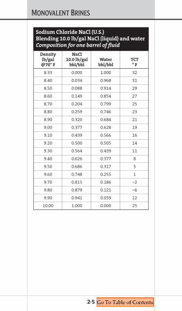
2·5
Density NaCllb/gal 10.0 lb/gal Water TCT@70° F bbl/bbl bbl/bbl ° F
8.33 0.000 1.000 32
8.40 0.034 0.968 31
8.50 0.088 0.914 29
8.60 0.149 0.854 27
8.70 0.204 0.799 25
8.80 0.259 0.746 23
8.90 0.320 0.684 21
9.00 0.377 0.628 19
9.10 0.439 0.566 16
9.20 0.500 0.505 14
9.30 0.564 0.439 11
9.40 0.626 0.377 8
9.50 0.686 0.317 5
9.60 0.748 0.255 1
9.70 0.815 0.186 –2
9.80 0.879 0.121 –6
9.90 0.941 0.059 12
10.00 1.000 0.000 25
Sodium Chloride NaCl (U.S.)
Blending 10.0 lb/gal NaCl (liquid) and water
Composition for one barrel of fluid
MONOVALENT BRINES
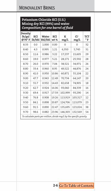
2·6
Densitylb/gal KCl Water KCl K Cl– TCT@70° F lb/bbl bbl/bbl wt % mg/L mg/L ° F
8.33 0.0 1.000 0.00 0 0 32
8.40 4.3 0.995 1.21 6,350 5,745 31
8.50 11.6 0.986 3.22 17,237 15,605 29
8.60 19.0 0.977 5.21 28,171 25,592 28
8.70 26.0 0.970 7.04 38,521 34,971 26
8.80 33.4 0.960 8.95 49,522 44,876 24
8.90 41.0 0.950 10.86 60,871 55,104 22
9.00 47.7 0.943 12.49 70,734 64,147 20
9.10 55.7 0.932 14.43 82,658 74,905 18
9.20 62.7 0.924 16.06 93,060 84,339 16
9.30 69.4 0.917 17.59 102,999 93,290 14
9.40 76.8 0.908 19.26 113,919 103,317 12
9.50 84.1 0.898 20.87 124,706 113,079 23
9.60 91.5 0.890 22.47 135,695 123,024 38
9.70 98.6 0.882 23.96 146,303 132,569 54
To calculate parts per million, divide mg/L by the specific gravity.
Potassium Chloride KCl (U.S.)
Mixing dry KCl (99%) and water
Composition for one barrel of fluid

MONOVALENT BRINES
2·7
Density NaBrlb/gal Water 97% dry NaBr Na Br TCT@70° F bbl/bbl lb/bbl wt % mg/L mg/L ° F
9.0 0.973 37.9 9.73 23,434 81,533 24
9.1 0.969 43.4 11.01 26,861 93,359 23
9.2 0.965 48.9 12.28 30,247 105,203 0
9.3 0.961 54.5 13.53 33,701 117,282 21
9.4 0.957 60.2 14.79 37,334 129,597 19
9.5 0.953 65.8 16.00 40,809 141,577 17
9.6 0.948 71.5 17.20 44,233 153,895 16
9.7 0.944 77.2 18.38 47,837 166,090 14
9.8 0.940 83.0 19.56 51,387 178,620 12
9.9 0.935 88.7 20.69 54,881 190,896 11
10.0 0.931 94.5 21.83 58,555 203,384 9
10.1 0.926 100.3 22.94 62,171 215,840 7
10.2 0.922 106.1 24.02 65,724 228,258 5
10.3 0.917 111.9 25.09 69,334 240,754 4
10.4 0.912 117.8 26.16 73,002 253,449 2
10.5 0.907 123.6 27.19 76,602 265,965 0
10.6 0.903 129.5 28.22 80,257 278,673 –2
10.7 0.898 135.3 29.20 83,838 291,188 –4
10.8 0.893 141.2 30.19 87,473 303,888 –6
10.9 0.888 147.1 31.17 91,160 316,511 –7
11.0 0.884 153.0 32.12 94,768 329,182 –9
11.1 0.879 158.9 33.06 98,427 341,897 –11
11.2 0.874 164.7 33.96 102,001 354,384 –13
11.3 0.869 174.6 35.69 108,200 375,718 –14
11.4 0.864 176.5 35.76 109,294 379,863 –16
11.5 0.859 182.4 36.63 113,013 392,441 –18
11.6 0.855 188.3 37.49 116,640 405,179 –19
Sodium Bromide NaBr (U.S.)
Mixing dry NaBr (97%) and water
Composition for one barrel of fluid
Continues on next page

MONOVALENT BRINES
2·8
Density NaBrlb/gal Water 97% dry NaBr Na Br TCT@70° F bbl/bbl lb/bbl wt % mg/L mg/L ° F
11.7 0.850 194.2 38.33 120,313 417,937 –19
11.8 0.845 200.1 39.16 123,890 430,571 –16
11.9 0.840 206.0 39.98 127,653 443,216 –11
12.0 0.835 211.9 40.78 131,174 456,012 –5
12.1 0.830 217.8 41.57 134,880 468,668 2
12.2 0.826 223.6 42.33 138,483 481,178 10
12.3 0.821 229.5 43.09 142,127 493,830 19
12.4 0.816 235.4 43.84 145,812 506,475 28
12.5 0.811 241.2 44.56 149,388 518,958 37
12.6 0.807 247.2 45.31 153,153 531,879 46
12.7 0.804 252.5 45.92 156,350 543,415 54
To calculate parts per million, divide mg/L by the specific gravity.
Sodium Bromide NaBr (U.S.)
Mixing dry NaBr (97%) and water
Composition for one barrel of fluid
Continued from previous page

MONOVALENT BRINES
2·9
Density NaBrlb/gal 12.5 lb/gal Water TCT@70° F bbl/bbl bbl/bbl ° F
9.0 0.157 0.845 24
9.1 0.180 0.822 23
9.2 0.203 0.800 0
9.3 0.226 0.777 21
9.4 0.250 0.754 19
9.5 0.273 0.731 17
9.6 0.296 0.708 16
9.7 0.320 0.684 14
9.8 0.344 0.660 12
9.9 0.368 0.637 11
10.0 0.392 0.613 9
10.1 0.416 0.588 7
10.2 0.440 0.564 5
10.3 0.464 0.540 4
10.4 0.488 0.516 2
10.5 0.512 0.492 0
10.6 0.537 0.467 –2
10.7 0.561 0.443 –4
10.8 0.585 0.418 –6
10.9 0.610 0.393 –7
Sodium Bromide NaBr (U.S.)
Blending 12.5 lb/gal NaBr (liquid) and water
Composition for one barrel of fluid
Continues on next page

MONOVALENT BRINES
2·10
Density NaBrlb/gal 12.5 lb/gal Water TCT@70° F bbl/bbl bbl/bbl ° F
11.0 0.634 0.369 –9
11.1 0.659 0.344 –11
11.2 0.683 0.320 –13
11.3 0.707 0.295 –14
11.4 0.732 0.270 –16
11.5 0.756 0.246 –18
11.6 0.781 0.221 –19
11.7 0.805 0.196 –19
11.8 0.830 0.172 –16
11.9 0.854 0.147 –11
12.0 0.879 0.122 –5
12.1 0.903 0.098 2
12.2 0.927 0.073 10
12.3 0.951 0.049 19
12.4 0.976 0.024 28
12.5 1.000 0.000 37
Sodium Bromide NaBr (U.S.)
Blending 12.5 lb/gal NaBr (liquid) and water
Composition for one barrel of fluid
Continued from previous page
MONOVALENT BRINES
2·11
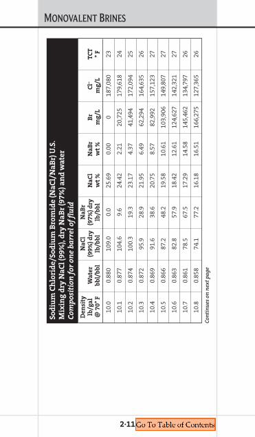
De
nsi
tyN
aC
l N
aB
r lb
/ga
lW
ate
r(9
9%
) d
ry(9
7%
) d
ryN
aC
lN
aB
rB
rC
l–T
CT
@ 7
0°
Fb
bl/
bb
llb
/bb
llb
/bb
lw
t %
wt
%m
g/L
mg
/L°
F
10.0
0.88
010
9.0
0.0
25.6
90.
000
187,
080
23
10.1
0.87
710
4.6
9.6
24.4
22.
2120
,725
179,
618
24
10.2
0.87
410
0.3
19.3
23.1
74.
3741
,494
172,
094
25
10.3
0.87
295
.928
.921
.95
6.49
62,2
9416
4,63
526
10.4
0.86
991
.638
.620
.75
8.57
82,9
9215
7,12
327
10.5
0.86
687
.248
.219
.58
10.6
110
3,90
614
9,80
727
10.6
0.86
382
.857
.918
.42
12.6
112
4,62
714
2,32
127
10.7
0.86
178
.567
.517
.29
14.5
814
5,46
213
4,79
726
10.8
0.85
874
.177
.216
.18
16.5
116
6,27
512
7,36
526
So
diu
m C
hlo
rid
e/S
od
ium
Bro
mid
e (
Na
Cl/
Na
Br)
U.S
.
Mix
ing
dry
Na
Cl
(99
%),
dry
Na
Br
(97
%)
an
d w
ate
r
Co
mp
osi
tio
n f
or
on
e b
arr
el
of
flu
id
Con
tin
ues
on
nex
t p
age

MONOVALENT BRINES
2·12
De
nsi
tyN
aC
l N
aB
r lb
/ga
lW
ate
r(9
9%
) d
ry(9
7%
) d
ryN
aC
lN
aB
rB
rC
l–T
CT
@ 7
0°
Fb
bl/
bb
llb
/bb
llb
/bb
lw
t %
wt
%m
g/L
mg
/L°
F
10.9
0.85
569
.886
.815
.09
18.4
018
7,05
611
9,77
426
11.0
0.85
265
.496
.514
.01
20.2
620
7,79
311
2,28
525
11.1
0.85
061
.010
6.1
12.9
622
.08
228,
610
104,
907
24
11.2
0.84
756
.711
5.8
11.9
323
.87
249,
363
97,3
7824
11.3
0.84
452
.312
5.4
10.9
125
.63
270,
179
89,8
3325
11.4
0.84
148
.013
5.1
9.92
27.3
629
0,91
382
,414
26
11.5
0.83
943
.614
4.7
8.94
29.0
631
1,69
274
,850
28
11.6
0.83
639
.215
4.4
7.97
30.7
333
2,50
967
,421
29
So
diu
m C
hlo
rid
e/S
od
ium
Bro
mid
e (
Na
Cl/
Na
Br)
U.S
.
Mix
ing
dry
Na
Cl
(99
%),
dry
Na
Br
(97
%)
an
d w
ate
r
Co
mp
osi
tio
n f
or
on
e b
arr
el
of
flu
id
Con
tin
ues
on
nex
t p
age
Con
tin
ued
from
pre
viou
s p
age
MONOVALENT BRINES
2·13
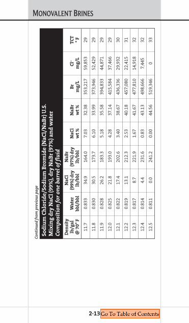
De
nsi
tyN
aC
l N
aB
r lb
/ga
lW
ate
r(9
9%
) d
ry(9
7%
) d
ryN
aC
lN
aB
rB
rC
l–T
CT
@ 7
0°
Fb
bl/
bb
llb
/bb
llb
/bb
lw
t %
wt
%m
g/L
mg
/L°
F
11.7
0.83
334
.916
4.0
7.03
32.3
835
3,21
759
,853
29
11.8
0.83
030
.517
3.7
6.10
33.9
937
3,94
652
,429
29
11.9
0.82
826
.218
3.3
5.18
35.5
839
4,83
344
,871
29
12.0
0.82
521
.819
3.0
4.28
37.1
441
5,58
437
,466
29
12.1
0.82
217
.420
2.6
3.40
38.6
743
6,33
629
,932
30
12.2
0.81
913
.121
2.3
2.53
40.1
845
7,08
022
,415
31
12.3
0.81
78.
722
1.9
1.67
41.6
747
7,81
014
,918
32
12.4
0.81
44.
423
1.6
0.83
43.1
349
8,66
67,
445
32
12.5
0.81
10.
024
1.2
0.00
44.5
651
9,34
60
33
So
diu
m C
hlo
rid
e/S
od
ium
Bro
mid
e (
Na
Cl/
Na
Br)
U.S
.
Mix
ing
dry
Na
Cl
(99
%),
dry
Na
Br
(97
%)
an
d w
ate
r
Co
mp
osi
tio
n f
or
on
e b
arr
el
of
flu
id
Con
tin
ued
from
pre
viou
s p
age
MONOVALENT BRINES
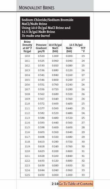
2·14
BrineDensity Pressure 10.0 lb/gal 12.5 lb/galat 60° F Gradient NaCl NaBr TCTlb/gal psi/ft (bbl) (bbl) ° F
10.0 0.520 1.000 0.000 23
10.1 0.525 0.960 0.040 24
10.2 0.530 0.920 0.080 25
10.3 0.536 0.880 0.120 26
10.4 0.541 0.840 0.160 27
10.5 0.546 0.800 0.200 27
10.6 0.551 0.760 0.240 26
10.7 0.556 0.720 0.280 26
10.8 0.562 0.680 0.320 26
10.9 0.567 0.640 0.360 26
11.0 0.572 0.600 0.400 25
11.1 0.577 0.560 0.440 25
11.2 0.582 0.520 0.480 24
11.3 0.588 0.480 0.520 25
11.4 0.593 0.440 0.560 27
11.5 0.598 0.400 0.600 28
11.6 0.603 0.360 0.640 29
11.7 0.608 0.320 0.680 29
11.8 0.613 0.280 0.720 30
11.9 0.618 0.240 0.760 30
12.0 0.623 0.200 0.800 31
12.1 0.628 0.160 0.840 31
12.2 0.633 0.120 0.880 32
12.3 0.639 0.080 0.920 32
12.4 0.644 0.040 0.960 33
12.5 0.650 0.000 1.000 33
Sodium Chloride/Sodium Bromide
NaCl/NaBr Brine
Using 10.0 lb/gal NaCl Brine and
12.5 lb/gal NaBr Brine
To make one barrel
MONOVALENT BRINES
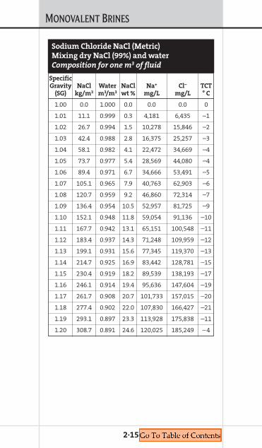
2·15
SpecificGravity NaCl Water NaCl Na+ Cl– TCT
(SG) kg/m3 m3/m3 wt % mg/L mg/L ° C
1.00 0.0 1.000 0.0 0.0 0.0 0
1.01 11.1 0.999 0.3 4,181 6,435 –1
1.02 26.7 0.994 1.5 10,278 15,846 –2
1.03 42.4 0.988 2.8 16,375 25,257 –3
1.04 58.1 0.982 4.1 22,472 34,669 –4
1.05 73.7 0.977 5.4 28,569 44,080 –4
1.06 89.4 0.971 6.7 34,666 53,491 –5
1.07 105.1 0.965 7.9 40,763 62,903 –6
1.08 120.7 0.959 9.2 46,860 72,314 –7
1.09 136.4 0.954 10.5 52,957 81,725 –9
1.10 152.1 0.948 11.8 59,054 91,136 –10
1.11 167.7 0.942 13.1 65,151 100,548 –11
1.12 183.4 0.937 14.3 71,248 109,959 –12
1.13 199.1 0.931 15.6 77,345 119,370 –13
1.14 214.7 0.925 16.9 83,442 128,781 –15
1.15 230.4 0.919 18.2 89,539 138,193 –17
1.16 246.1 0.914 19.4 95,636 147,604 –19
1.17 261.7 0.908 20.7 101,733 157,015 –20
1.18 277.4 0.902 22.0 107,830 166,427 –21
1.19 293.1 0.897 23.3 113,928 175,838 –11
1.20 308.7 0.891 24.6 120,025 185,249 –4
Sodium Chloride NaCl (Metric)
Mixing dry NaCl (99%) and water
Composition for one m3 of fluid
MONOVALENT BRINES
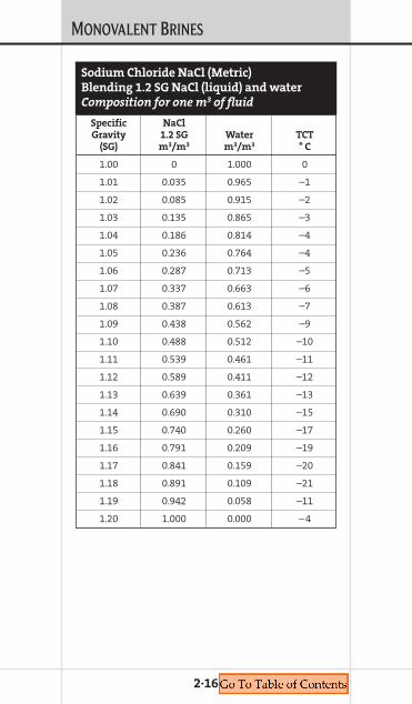
2·16
Specific NaClGravity 1.2 SG Water TCT
(SG) m3/m3 m3/m3 ° C
1.00 0 1.000 0
1.01 0.035 0.965 –1
1.02 0.085 0.915 –2
1.03 0.135 0.865 –3
1.04 0.186 0.814 –4
1.05 0.236 0.764 –4
1.06 0.287 0.713 –5
1.07 0.337 0.663 –6
1.08 0.387 0.613 –7
1.09 0.438 0.562 –9
1.10 0.488 0.512 –10
1.11 0.539 0.461 –11
1.12 0.589 0.411 –12
1.13 0.639 0.361 –13
1.14 0.690 0.310 –15
1.15 0.740 0.260 –17
1.16 0.791 0.209 –19
1.17 0.841 0.159 –20
1.18 0.891 0.109 –21
1.19 0.942 0.058 –11
1.20 1.000 0.000 –4
Sodium Chloride NaCl (Metric)
Blending 1.2 SG NaCl (liquid) and water
Composition for one m3 of fluid
MONOVALENT BRINES
2·17
Specific KCl (99%)Gravity Water dry KCl TCT
(SG) m3/m3 kg/m3 wt % ° C
1.00 0.9983 4.6 0.5 0
1.01 0.9942 15.7 1.6 –1
1.02 0.9882 31.7 3.1 –2
1.03 0.982 47.9 4.7 –2
1.04 0.9756 64.2 6.2 –3
1.05 0.969 80.7 7.7 –4
1.06 0.9623 97.4 9.2 –5
1.07 0.9554 114.2 10.7 –5
1.08 0.9484 131.2 12.2 –6
1.09 0.9412 148.3 13.6 –7
1.10 0.9339 165.5 15.1 –8
1.11 0.9266 182.9 16.5 –9
1.12 0.9191 200.3 17.9 –10
1.13 0.9115 217.9 19.3 –11
1.14 0.9038 235.5 20.7 –6
1.15 0.8961 253.2 22.1 1
1.16 0.8883 270.9 23.4 8
1.17 0.8805 288.7 24.7 15
1.18 0.8726 306.5 26 23
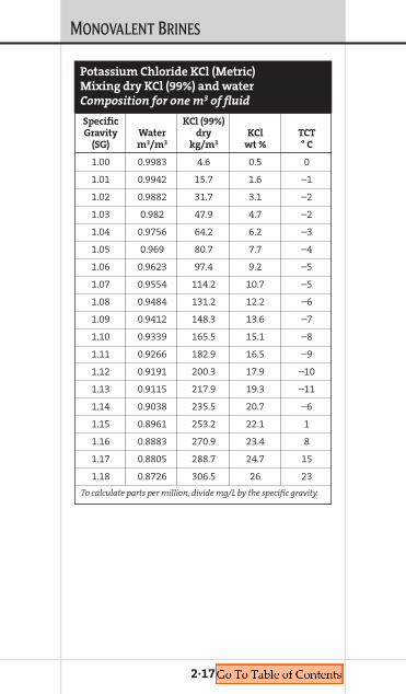
To calculate parts per million, divide mg/L by the specific gravity.
Potassium Chloride KCl (Metric)
Mixing dry KCl (99%) and water
Composition for one m3 of fluid
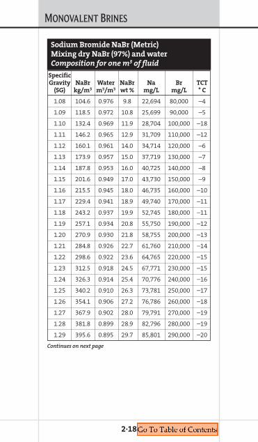
MONOVALENT BRINES
2·18
SpecificGravity NaBr Water NaBr Na Br TCT
(SG) kg/m3 m3/m3 wt % mg/L mg/L ° C
1.08 104.6 0.976 9.8 22,694 80,000 –4
1.09 118.5 0.972 10.8 25,699 90,000 –5
1.10 132.4 0.969 11.9 28,704 100,000 –18
1.11 146.2 0.965 12.9 31,709 110,000 –12
1.12 160.1 0.961 14.0 34,714 120,000 –6
1.13 173.9 0.957 15.0 37,719 130,000 –7
1.14 187.8 0.953 16.0 40,725 140,000 –8
1.15 201.6 0.949 17.0 43,730 150,000 –9
1.16 215.5 0.945 18.0 46,735 160,000 –10
1.17 229.4 0.941 18.9 49,740 170,000 –11
1.18 243.2 0.937 19.9 52,745 180,000 –11
1.19 257.1 0.934 20.8 55,750 190,000 –12
1.20 270.9 0.930 21.8 58,755 200,000 –13
1.21 284.8 0.926 22.7 61,760 210,000 –14
1.22 298.6 0.922 23.6 64,765 220,000 –15
1.23 312.5 0.918 24.5 67,771 230,000 –15
1.24 326.3 0.914 25.4 70,776 240,000 –16
1.25 340.2 0.910 26.3 73,781 250,000 –17
1.26 354.1 0.906 27.2 76,786 260,000 –18
1.27 367.9 0.902 28.0 79,791 270,000 –19
1.28 381.8 0.899 28.9 82,796 280,000 –19
1.29 395.6 0.895 29.7 85,801 290,000 –20
Sodium Bromide NaBr (Metric)
Mixing dry NaBr (97%) and water
Composition for one m3 of fluid
Continues on next page
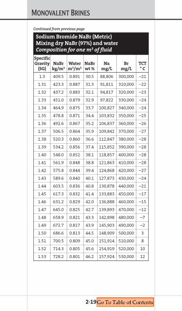
MONOVALENT BRINES
2·19
SpecificGravity NaBr Water NaBr Na Br TCT
(SG) kg/m3 m3/m3 wt % mg/L mg/L ° C
1.3 409.5 0.891 30.5 88,806 300,000 –21
1.31 423.3 0.887 31.3 91,811 310,000 –22
1.32 437.2 0.883 32.1 94,817 320,000 –23
1.33 451.0 0.879 32.9 97,822 330,000 –24
1.34 464.9 0.875 33.7 100,827 340,000 –24
1.35 478.8 0.871 34.4 103,832 350,000 –25
1.36 492.6 0.867 35.2 106,837 360,000 –26
1.37 506.5 0.864 35.9 109,842 370,000 –27
1.38 520.3 0.860 36.6 112,847 380,000 –28
1.39 534.2 0.856 37.4 115,852 390,000 –28
1.40 548.0 0.852 38.1 118,857 400,000 –28
1.41 561.9 0.848 38.8 121,863 410,000 –28
1.42 575.8 0.844 39.4 124,868 420,000 –27
1.43 589.6 0.840 40.1 127,873 430,000 –24
1.44 603.5 0.836 40.8 130,878 440,000 –21
1.45 617.3 0.832 41.4 133,883 450,000 –17
1.46 631.2 0.829 42.0 136,888 460,000 –15
1.47 645.0 0.825 42.7 139,893 470,000 –12
1.48 658.9 0.821 43.3 142,898 480,000 –7
1.49 672.7 0.817 43.9 145,903 490,000 –2
1.50 686.6 0.813 44.5 148,909 500,000 3
1.51 700.5 0.809 45.0 151,914 510,000 8
1.52 714.3 0.805 45.6 154,919 520,000 10
1.53 728.2 0.801 46.2 157,924 530,000 12
Continued from previous page
Sodium Bromide NaBr (Metric)
Mixing dry NaBr (97%) and water
Composition for one m3 of fluid
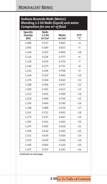
MONOVALENT BRINES
2·20
Specific NaBrGravity 1.5 SG Water TCT
(SG) m3/m3 m3/m3 ° C
1.080 0.157 0.845 –4
1.092 0.180 0.822 –5
1.104 0.203 0.800 –18
1.116 0.226 0.777 –6
1.128 0.250 0.754 –7
1.140 0.273 0.731 –8
1.152 0.296 0.708 –9
1.164 0.320 0.684 –10
1.176 0.344 0.660 –11
1.188 0.368 0.637 –12
1.200 0.392 0.613 –13
1.212 0.416 0.588 –14
1.224 0.440 0.564 –15
1.236 0.464 0.540 –16
1.248 0.488 0.516 –17
1.261 0.512 0.492 –18
1.273 0.537 0.467 –19
1.285 0.561 0.443 –20
1.297 0.585 0.418 –21
1.309 0.610 0.393 –22
1.321 0.634 0.369 –23
1.333 0.659 0.344 –24
1.345 0.683 0.320 –25
1.357 0.707 0.295 –26
Sodium Bromide NaBr (Metric)
Blending 1.5 SG NaBr (liquid) and water
Composition for one m3 of fluid
Continues on next page

MONOVALENT BRINES
2·21
Specific NaBrGravity 1.5 SG Water TCT
(SG) m3/m3 m3/m3 ° C
1.369 0.732 0.270 –27
1.381 0.756 0.246 –28
1.393 0.781 0.221 –28
1.405 0.805 0.196 –28
1.417 0.830 0.172 –27
1.429 0.854 0.147 –24
1.441 0.879 0.122 –21
1.453 0.903 0.098 –17
1.465 0.927 0.073 –12
1.477 0.951 0.049 –7
1.489 0.976 0.024 –2
1.501 1.000 0.000 3
Sodium Bromide NaBr (Metric)
Blending 1.5 SG NaBr (liquid) and water
Composition for one m3 of fluid
Continued from previous page

MONOVALENT BRINES
2·22
Sp
eci
fic
Na
Cl
Na
Br
Gra
vit
yW
ate
r(9
9%
) d
ry(9
7%
) d
ryN
aC
lN
aB
rB
rC
l–T
CT
(SG
)m
3/m
3k
g/m
3k
g/m
3w
t %
wt
%m
g/L
mg
/L°
C
1.20
00.
880
311.
30.
025
.69
0.00
018
7,08
0–5
1.21
20.
877
298.
727
.424
.42
2.21
20,7
2517
9,61
8–4
1.22
40.
874
286.
555
.123
.17
4.37
41,4
9417
2,09
4–4
1.23
60.
872
273.
982
.521
.95
6.49
62,2
9416
4,63
5–3
1.24
80.
869
261.
611
0.2
20.7
58.
5782
,992
157,
123
–3
1.26
10.
866
249.
013
7.7
19.5
810
.61
103,
906
149,
807
–3
1.27
30.
863
236.
516
5.4
18.4
212
.61
124,
627
142,
321
–3
1.28
50.
861
224.
219
2.8
17.2
914
.58
145,
462
134,
797
–3
1.29
70.
858
211.
622
0.5
16.1
816
.51
166,
275
127,
365
–3
So
diu
m C
hlo
rid
e/S
od
ium
Bro
mid
e N
aC
l/N
aB
r (M
etr
ic)
Mix
ing
dry
Na
Cl
(99
%),
dry
Na
Br
(97
%)
an
d w
ate
r
Co
mp
osi
tio
n f
or
on
e m
3o
f fl
uid
Con
tin
ues
on
nex
t p
age
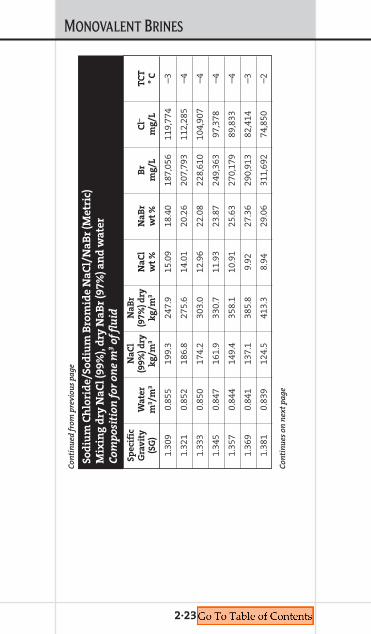
MONOVALENT BRINES
2·23
Sp
eci
fic
Na
Cl
Na
Br
Gra
vit
yW
ate
r(9
9%
) d
ry(9
7%
) d
ryN
aC
lN
aB
rB
rC
l–T
CT
(SG
)m
3/m
3k
g/m
3k
g/m
3w
t %
wt
%m
g/L
mg
/L°
C
1.30
90.
855
199.
324
7.9
15.0
918
.40
187,
056
119,
774
–3
1.32
10.
852
186.
827
5.6
14.0
120
.26
207,
793
112,
285
–4
1.33
30.
850
174.
230
3.0
12.9
622
.08
228,
610
104,
907
–4
1.34
50.
847
161.
933
0.7
11.9
323
.87
249,
363
97,3
78–4
1.35
70.
844
149.
435
8.1
10.9
125
.63
270,
179
89,8
33–4
1.36
90.
841
137.
138
5.8
9.92
27.3
629
0,91
382
,414
–3
1.38
10.
839
124.
541
3.3
8.94
29.0
631
1,69
274
,850
–2
So
diu
m C
hlo
rid
e/S
od
ium
Bro
mid
e N
aC
l/N
aB
r (M
etr
ic)
Mix
ing
dry
Na
Cl
(99
%),
dry
Na
Br
(97
%)
an
d w
ate
r
Co
mp
osi
tio
n f
or
on
e m
3o
f fl
uid
Con
tin
ues
on
nex
t p
age
Con
tin
ued
from
pre
viou
s p
age

MONOVALENT BRINES
2·24
Sp
eci
fic
Na
Cl
Na
Br
Gra
vit
yW
ate
r(9
9%
) d
ry(9
7%
) d
ryN
aC
lN
aB
rB
rC
l–T
CT
(SG
)m
3/m
3k
g/m
3k
g/m
3w
t %
wt
%m
g/L
mg
/L°
C
1.39
30.
836
112.
044
1.0
7.97
30.7
333
2,50
967
,421
–2
1.40
50.
833
99.7
468.
47.
0332
.38
353,
217
59,8
53–2
1.41
70.
830
87.1
496.
16.
1033
.99
373,
946
52,4
29–2
1.42
90.
828
74.8
523.
55.
1835
.58
394,
833
44,8
71–2
1.44
10.
825
62.3
551.
24.
2837
.14
415,
584
37,4
66–2
1.45
30.
822
49.7
578.
63.
4038
.67
436,
336
29,9
32–1
1.46
50.
819
37.4
606.
32.
5340
.18
457,
080
22,4
15–1
So
diu
m C
hlo
rid
e/S
od
ium
Bro
mid
e N
aC
l/N
aB
r (M
etr
ic)
Mix
ing
dry
Na
Cl
(99
%),
dry
Na
Br
(97
%)
an
d w
ate
r
Co
mp
osi
tio
n f
or
on
e m
3o
f fl
uid
Con
tin
ues
on
nex
t p
age
Con
tin
ued
from
pre
viou
s p
age

MONOVALENT BRINES
2·25
Sp
eci
fic
Na
Cl
Na
Br
Gra
vit
yW
ate
r(9
9%
) d
ry(9
7%
) d
ryN
aC
lN
aB
rB
rC
l–T
CT
(SG
)m
3/m
3k
g/m
3k
g/m
3w
t %
wt
%m
g/L
mg
/L°
C
1.47
70.
817
24.8
633.
71.
6741
.67
477,
810
14,9
180
1.48
90.
814
12.6
661.
40.
8343
.13
498,
666
7,44
50
1.50
10.
811
0.0
688.
90.
0044
.56
519,
346
01
To c
alcu
late
par
ts p
er m
illio
n, d
ivid
e m
g/L
by th
e sp
ecif
ic g
ravi
ty.
So
diu
m C
hlo
rid
e/S
od
ium
Bro
mid
e N
aC
l/N
aB
r (M
etr
ic)
Mix
ing
dry
Na
Cl
(99
%),
dry
Na
Br
(97
%)
an
d w
ate
r
Co
mp
osi
tio
n f
or
on
e m
3o
f fl
uid
Con
tin
ued
from
pre
viou
s p
age

MONOVALENT BRINES
2·26
Specific NaCl NaBrGravity 1.2 SG 1.5 SG TCT
(SG) m3 m3 ° C
1.200 1.000 0.000 –5
1.212 0.960 0.040 –4
1.224 0.920 0.080 –4
1.236 0.880 0.120 –3
1.248 0.840 0.160 –3
1.261 0.800 0.200 –3
1.273 0.760 0.240 –3
1.285 0.720 0.280 –3
1.297 0.680 0.320 –3
1.309 0.640 0.360 –3
1.321 0.600 0.400 –4
1.333 0.560 0.440 –4
1.345 0.520 0.480 –4
1.357 0.480 0.520 –4
1.369 0.440 0.560 –3
1.381 0.400 0.600 –2
1.393 0.360 0.640 –2
1.405 0.320 0.680 –2
1.417 0.280 0.720 –2
1.429 0.240 0.760 –2
1.441 0.200 0.800 –2
Sodium Chloride/Sodium Bromide
NaCl/NaBr (Metric)
Blending 1.2 SG NaCl (liquid),
1.5 SG NaBr (liquid) and water
Composition for one m3 of fluid
Continues on next page
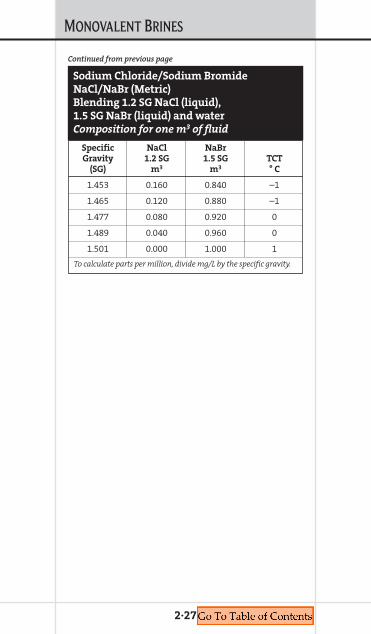
MONOVALENT BRINES
2·27
Specific NaCl NaBrGravity 1.2 SG 1.5 SG TCT
(SG) m3 m3 ° C
1.453 0.160 0.840 –1
1.465 0.120 0.880 –1
1.477 0.080 0.920 0
1.489 0.040 0.960 0
1.501 0.000 1.000 1
To calculate parts per million, divide mg/L by the specific gravity.
Sodium Chloride/Sodium Bromide
NaCl/NaBr (Metric)
Blending 1.2 SG NaCl (liquid),
1.5 SG NaBr (liquid) and water
Composition for one m3 of fluid
Continued from previous page

MONOVALENT BRINES
2·28
Density 96% lb/gal NaHCO2 Water TCT@70° F lb/bbl bbl/bbl ° F
8.4 5.86 0.9929 31
8.5 12.23 0.9867 29
8.6 18.71 0.9801 27
8.7 25.31 0.9733 25
8.8 32.02 0.9661 23
8.9 38.86 0.9585 20
9.0 45.83 0.9506 18
9.1 52.92 0.9423 16
9.2 60.14 0.9337 13
9.3 67.49 0.9247 11
9.4 74.98 0.9153 8
9.5 82.60 0.9055 6
9.6 90.36 0.8953 3
9.7 98.26 0.8847 6
9.8 106.30 0.8737 9
9.9 114.50 0.8623 12
10.0 122.80 0.8504 15
10.1 131.30 0.8382 18
10.2 140.00 0.8254 22
10.3 148.80 0.8123 27
10.4 157.70 0.7986 32
10.5 166.90 0.7845 38
10.6 176.10 0.7700 44
10.7 185.60 0.7549 49
10.8 195.20 0.7394 54
10.9 205.00 0.7233 59
11.0 215.00 0.7068 70
Sodium Formate NaHCO2 (U.S.)
Mixing dry NaHCO2 (96%) and water
Composition for one barrel of fluid
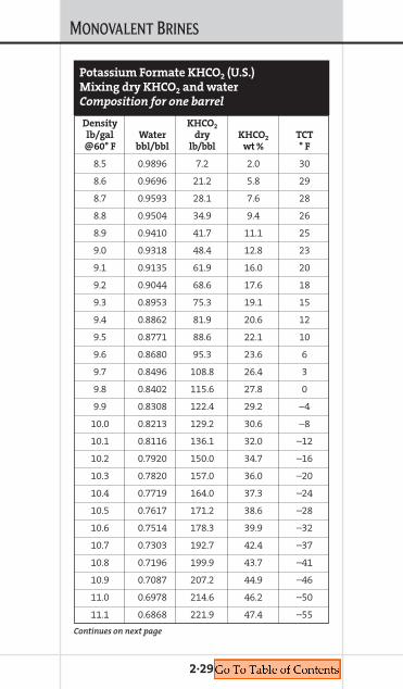
MONOVALENT BRINES
2·29
Density KHCO2
lb/gal Water dry KHCO2 TCT@60° F bbl/bbl lb/bbl wt % ° F
8.5 0.9896 7.2 2.0 30
8.6 0.9696 21.2 5.8 29
8.7 0.9593 28.1 7.6 28
8.8 0.9504 34.9 9.4 26
8.9 0.9410 41.7 11.1 25
9.0 0.9318 48.4 12.8 23
9.1 0.9135 61.9 16.0 20
9.2 0.9044 68.6 17.6 18
9.3 0.8953 75.3 19.1 15
9.4 0.8862 81.9 20.6 12
9.5 0.8771 88.6 22.1 10
9.6 0.8680 95.3 23.6 6
9.7 0.8496 108.8 26.4 3
9.8 0.8402 115.6 27.8 0
9.9 0.8308 122.4 29.2 –4
10.0 0.8213 129.2 30.6 –8
10.1 0.8116 136.1 32.0 –12
10.2 0.7920 150.0 34.7 –16
10.3 0.7820 157.0 36.0 –20
10.4 0.7719 164.0 37.3 –24
10.5 0.7617 171.2 38.6 –28
10.6 0.7514 178.3 39.9 –32
10.7 0.7303 192.7 42.4 –37
10.8 0.7196 199.9 43.7 –41
10.9 0.7087 207.2 44.9 –46
11.0 0.6978 214.6 46.2 –50
11.1 0.6868 221.9 47.4 –55
Potassium Formate KHCO2 (U.S.)
Mixing dry KHCO2 and water
Composition for one barrel
Continues on next page
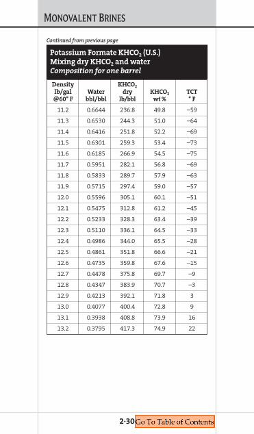
MONOVALENT BRINES
2·30
Density KHCO2
lb/gal Water dry KHCO2 TCT@60° F bbl/bbl lb/bbl wt % ° F
11.2 0.6644 236.8 49.8 –59
11.3 0.6530 244.3 51.0 –64
11.4 0.6416 251.8 52.2 –69
11.5 0.6301 259.3 53.4 –73
11.6 0.6185 266.9 54.5 –75
11.7 0.5951 282.1 56.8 –69
11.8 0.5833 289.7 57.9 –63
11.9 0.5715 297.4 59.0 –57
12.0 0.5596 305.1 60.1 –51
12.1 0.5475 312.8 61.2 –45
12.2 0.5233 328.3 63.4 –39
12.3 0.5110 336.1 64.5 –33
12.4 0.4986 344.0 65.5 –28
12.5 0.4861 351.8 66.6 –21
12.6 0.4735 359.8 67.6 –15
12.7 0.4478 375.8 69.7 –9
12.8 0.4347 383.9 70.7 –3
12.9 0.4213 392.1 71.8 3
13.0 0.4077 400.4 72.8 9
13.1 0.3938 408.8 73.9 16
13.2 0.3795 417.3 74.9 22
Potassium Formate KHCO2 (U.S.)
Mixing dry KHCO2 and water
Composition for one barrel
Continued from previous page

MONOVALENT BRINES
2·31
Density KHCO2
lb/gal 13.1 lb/gal Water TCT@70° F bbl/bbl bbl/bbl ° F
8.4 0.0183 0.9817 30
8.5 0.0365 0.9635 29
8.6 0.0547 0.9453 28
8.7 0.0730 0.9270 26
8.8 0.0915 0.9085 25
8.9 0.1101 0.8899 23
9.0 0.1287 0.8713 20
9.1 0.1475 0.8525 18
9.2 0.1664 0.8336 15
9.3 0.1854 0.8146 12
9.4 0.2045 0.7955 10
9.5 0.2238 0.7762 6
9.6 0.2432 0.7568 3
9.7 0.2626 0.7374 0
9.8 0.2822 0.7178 –4
9.9 0.3019 0.6981 –8
10.0 0.3218 0.6782 –12
10.1 0.3418 0.6582 –16
10.2 0.3618 0.6382 –20
10.3 0.3821 0.6179 –24
10.4 0.4024 0.5976 –28
10.5 0.4229 0.5771 –32
10.6 0.4435 0.5565 –37
10.7 0.4642 0.5358 –41
10.8 0.4850 0.5150 –46
10.9 0.5060 0.4940 –50
11.0 0.5271 0.4729 –55
Potassium Formate KHCO2 (U.S.)
Blending 13.1 lb/gal KHCO2 (liquid) and water
Composition for one barrel
Continues on next page

MONOVALENT BRINES
2·32
Density KHCO2
lb/gal 13.1 lb/gal Water TCT@70° F bbl/bbl bbl/bbl ° F
11.1 0.5484 0.4516 –59
11.2 0.5698 0.4302 –64
11.3 0.5913 0.4087 –69
11.4 0.6129 0.3871 –73
11.5 0.6347 0.3653 –75
11.6 0.6567 0.3433 –69
11.7 0.6787 0.3213 –63
11.8 0.7009 0.2991 –57
11.9 0.7233 0.2767 –51
12.0 0.7458 0.2542 –45
12.1 0.7684 0.2316 –39
12.2 0.7912 0.2088 –33
12.3 0.8113 0.1887 –28
12.4 0.8372 0.1628 –21
12.5 0.8604 0.1396 –15
12.6 0.8837 0.1163 –9
12.7 0.9072 0.0928 –3
12.8 0.9309 0.0691 3
12.9 0.9547 0.0453 9
13.0 0.9786 0.0214 16
13.1 1.0000 0.0000 22
Potassium Formate KHCO2 (U.S.)
Blending 13.1 lb/gal KHCO2 (liquid) and water
Composition for one barrel
Continued from previous page
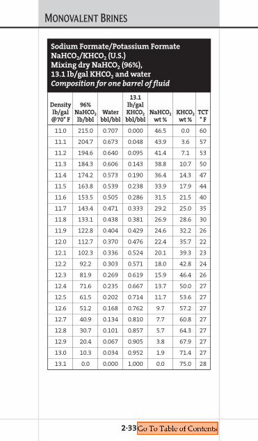
MONOVALENT BRINES
2·33
13.1 Density 96% lb/gallb/gal NaHCO2 Water KHCO2 NaHCO2 KHCO2 TCT@70° F lb/bbl bbl/bbl bbl/bbl wt % wt % ° F
11.0 215.0 0.707 0.000 46.5 0.0 60
11.1 204.7 0.673 0.048 43.9 3.6 57
11.2 194.6 0.640 0.095 41.4 7.1 53
11.3 184.3 0.606 0.143 38.8 10.7 50
11.4 174.2 0.573 0.190 36.4 14.3 47
11.5 163.8 0.539 0.238 33.9 17.9 44
11.6 153.5 0.505 0.286 31.5 21.5 40
11.7 143.4 0.471 0.333 29.2 25.0 35
11.8 133.1 0.438 0.381 26.9 28.6 30
11.9 122.8 0.404 0.429 24.6 32.2 26
12.0 112.7 0.370 0.476 22.4 35.7 22
12.1 102.3 0.336 0.524 20.1 39.3 23
12.2 92.2 0.303 0.571 18.0 42.8 24
12.3 81.9 0.269 0.619 15.9 46.4 26
12.4 71.6 0.235 0.667 13.7 50.0 27
12.5 61.5 0.202 0.714 11.7 53.6 27
12.6 51.2 0.168 0.762 9.7 57.2 27
12.7 40.9 0.134 0.810 7.7 60.8 27
12.8 30.7 0.101 0.857 5.7 64.3 27
12.9 20.4 0.067 0.905 3.8 67.9 27
13.0 10.3 0.034 0.952 1.9 71.4 27
13.1 0.0 0.000 1.000 0.0 75.0 28
Sodium Formate/Potassium Formate
NaHCO2/KHCO2 (U.S.)
Mixing dry NaHCO2 (96%),
13.1 lb/gal KHCO2 and water
Composition for one barrel of fluid
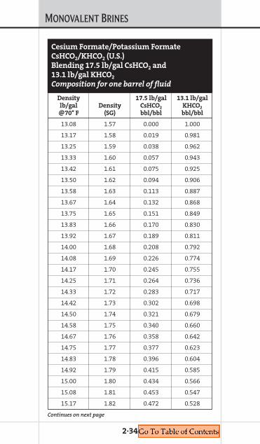
MONOVALENT BRINES
2·34
Density 17.5 lb/gal 13.1 lb/gallb/gal Density CsHCO2 KHCO2
@70° F (SG) bbl/bbl bbl/bbl
13.08 1.57 0.000 1.000
13.17 1.58 0.019 0.981
13.25 1.59 0.038 0.962
13.33 1.60 0.057 0.943
13.42 1.61 0.075 0.925
13.50 1.62 0.094 0.906
13.58 1.63 0.113 0.887
13.67 1.64 0.132 0.868
13.75 1.65 0.151 0.849
13.83 1.66 0.170 0.830
13.92 1.67 0.189 0.811
14.00 1.68 0.208 0.792
14.08 1.69 0.226 0.774
14.17 1.70 0.245 0.755
14.25 1.71 0.264 0.736
14.33 1.72 0.283 0.717
14.42 1.73 0.302 0.698
14.50 1.74 0.321 0.679
14.58 1.75 0.340 0.660
14.67 1.76 0.358 0.642
14.75 1.77 0.377 0.623
14.83 1.78 0.396 0.604
14.92 1.79 0.415 0.585
15.00 1.80 0.434 0.566
15.08 1.81 0.453 0.547
15.17 1.82 0.472 0.528
Cesium Formate/Potassium Formate
CsHCO2/KHCO2 (U.S.)
Blending 17.5 lb/gal CsHCO2 and
13.1 lb/gal KHCO2
Composition for one barrel of fluid
Continues on next page

MONOVALENT BRINES
2·35
Density 17.5 lb/gal 13.1 lb/gallb/gal Density CsHCO2 KHCO2
@70° F (SG) bbl/bbl bbl/bbl
15.25 1.83 0.491 0.509
15.33 1.84 0.509 0.491
15.42 1.85 0.528 0.472
15.50 1.86 0.547 0.453
15.58 1.87 0.566 0.434
15.67 1.88 0.585 0.415
15.75 1.89 0.604 0.396
15.83 1.90 0.623 0.377
15.92 1.91 0.642 0.358
16.00 1.92 0.660 0.340
16.08 1.93 0.679 0.321
16.17 1.94 0.698 0.302
16.25 1.95 0.717 0.283
16.33 1.96 0.736 0.264
16.42 1.97 0.755 0.245
16.50 1.98 0.774 0.226
16.58 1.99 0.792 0.208
16.67 2.00 0.811 0.189
16.75 2.01 0.830 0.170
16.83 2.02 0.849 0.151
16.92 2.03 0.868 0.132
17.00 2.04 0.887 0.113
17.08 2.05 0.906 0.094
Continued from previous page
Cesium Formate/Potassium Formate
CsHCO2/KHCO2 (U.S.)
Blending 17.5 lb/gal CsHCO2 and
13.1 lb/gal KHCO2
Composition for one barrel of fluid
Continues on next page
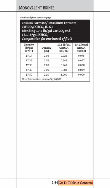
MONOVALENT BRINES
2·36
Density 17.5 lb/gal 13.1 lb/gallb/gal Density CsHCO2 KHCO2
@70° F (SG) bbl/bbl bbl/bbl
17.17 2.06 0.925 0.075
17.25 2.07 0.943 0.057
17.33 2.08 0.962 0.038
17.42 2.09 0.981 0.019
17.50 2.10 1.000 0.000
These formulations provided by CABOT.
Continued from previous page
Cesium Formate/Potassium Formate
CsHCO2/KHCO2 (U.S.)
Blending 17.5 lb/gal CsHCO2 and
13.1 lb/gal KHCO2
Composition for one barrel of fluid

MONOVALENT BRINES
2·37
Cesium Formate/Potassium Formate
CsHCO2/KHCO2 (U.S.)
Blending 18.3 lb/gal CsHCO2 and
13.1 lb/gal KHCO2
Composition for one barrel of fluid
Density CsHCO2 KHCO2
lb/gal 18.3 lb/gal 13.1 lb/gal Density@70° F bbl/bbl bbl/bbl SG
13.08 0.000 1.000 1.57
13.17 0.016 0.984 1.58
13.25 0.032 0.968 1.59
13.33 0.048 0.952 1.60
13.42 0.063 0.937 1.61
13.50 0.079 0.921 1.62
13.58 0.095 0.905 1.63
13.67 0.111 0.889 1.64
13.75 0.127 0.873 1.65
13.83 0.143 0.857 1.66
13.92 0.159 0.841 1.67
14.00 0.175 0.825 1.68
14.08 0.190 0.810 1.69
14.17 0.206 0.794 1.70
14.25 0.222 0.778 1.71
14.33 0.238 0.762 1.72
14.42 0.254 0.746 1.73
14.50 0.270 0.730 1.74
14.58 0.286 0.714 1.75
14.67 0.302 0.698 1.76
14.75 0.317 0.683 1.77
14.83 0.333 0.667 1.78
14.92 0.349 0.651 1.79
15.00 0.365 0.635 1.80
15.08 0.381 0.619 1.81
15.17 0.397 0.603 1.82
Continues on next page
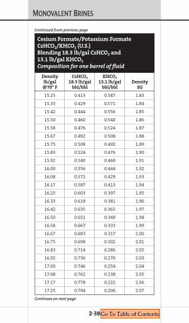
MONOVALENT BRINES
2·38
Cesium Formate/Potassium Formate
CsHCO2/KHCO2 (U.S.)
Blending 18.3 lb/gal CsHCO2 and
13.1 lb/gal KHCO2
Composition for one barrel of fluid
Density CsHCO2 KHCO2
lb/gal 18.3 lb/gal 13.1 lb/gal Density@70° F bbl/bbl bbl/bbl SG
15.25 0.413 0.587 1.83
15.33 0.429 0.571 1.84
15.42 0.444 0.556 1.85
15.50 0.460 0.540 1.86
15.58 0.476 0.524 1.87
15.67 0.492 0.508 1.88
15.75 0.508 0.492 1.89
15.83 0.524 0.476 1.90
15.92 0.540 0.460 1.91
16.00 0.556 0.444 1.92
16.08 0.571 0.429 1.93
16.17 0.587 0.413 1.94
16.25 0.603 0.397 1.95
16.33 0.619 0.381 1.96
16.42 0.635 0.365 1.97
16.50 0.651 0.349 1.98
16.58 0.667 0.333 1.99
16.67 0.683 0.317 2.00
16.75 0.698 0.302 2.01
16.83 0.714 0.286 2.02
16.92 0.730 0.270 2.03
17.00 0.746 0.254 2.04
17.08 0.762 0.238 2.05
17.17 0.778 0.222 2.06
17.25 0.794 0.206 2.07
Continues on next page
Continued from previous page

MONOVALENT BRINES
2·39
Cesium Formate/Potassium Formate
CsHCO2/KHCO2 (U.S.)
Blending 18.3 lb/gal CsHCO2 and
13.1 lb/gal KHCO2
Composition for one barrel of fluid
Density CsHCO2 KHCO2
lb/gal 18.3 lb/gal 13.1 lb/gal Density@70° F bbl/bbl bbl/bbl SG
17.33 0.810 0.190 2.08
17.42 0.825 0.175 2.09
17.50 0.841 0.159 2.10
17.58 0.857 0.143 2.11
17.67 0.873 0.127 2.12
17.75 0.889 0.111 2.13
17.83 0.905 0.095 2.14
17.92 0.921 0.079 2.15
18.00 0.937 0.063 2.16
18.08 0.952 0.048 2.17
18.17 0.968 0.032 2.18
18.25 0.984 0.016 2.19
18.33 1.000 0.000 2.20
These formulations provided by CABOT.
Continued from previous page
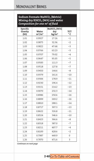
MONOVALENT BRINES
2·40
Sodium Formate NaHCO2 (Metric)
Mixing dry KHCO2 (96%) and water
Composition for one m3 of fluid
Specific NaHCO2 (96%)Gravity Water dry TCT
(SG) m3/m3 kg/m3 ° C
1.01 0.9927 17.26 –1
1.02 0.9875 32.36 –2
1.03 0.9822 47.68 –3
1.04 0.9766 63.23 –3
1.05 0.9707 79.02 –4
1.06 0.9647 95.05 –5
1.07 0.9583 111.3 –7
1.08 0.9518 127.8 –7
1.09 0.9450 144.6 –8
1.10 0.9379 161.6 –10
1.11 0.9306 178.9 –11
1.12 0.9230 196.4 –12
1.13 0.9151 214.2 –13
1.14 0.9070 232.3 –14
1.15 0.8986 250.6 –16
1.16 0.8899 269.2 –16
1.17 0.8810 288.1 –14
1.18 0.8717 307.3 –13
1.19 0.8622 326.8 –11
1.20 0.8524 346.6 –10
1.21 0.8423 366.6 –8
1.22 0.8318 387.0 –7
1.23 0.8211 407.7 –4
1.24 0.8100 428.6 –2
1.25 0.7987 449.9 0
1.26 0.7870 471.6 3
Continues on next page
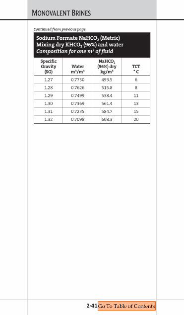
MONOVALENT BRINES
2·41
Sodium Formate NaHCO2 (Metric)
Mixing dry KHCO2 (96%) and water
Composition for one m3 of fluid
Specific NaHCO2
Gravity Water (96%) dry TCT(SG) m3/m3 kg/m3 ° C
1.27 0.7750 493.5 6
1.28 0.7626 515.8 8
1.29 0.7499 538.4 11
1.30 0.7369 561.4 13
1.31 0.7235 584.7 15
1.32 0.7098 608.3 20
Continued from previous page

MONOVALENT BRINES
2·42
Specific KHCO2
Gravity Water dry KHCO2 TCT(SG) m3/m3 kg/m3 wt % ° C
1.01 0.9896 20.4 2.0 –1
1.02 0.9795 40.5 3.9 –2
1.03 0.9696 60.4 5.8 –3
1.04 0.9593 80.1 7.6 –3
1.05 0.9504 99.6 9.4 –4
1.06 0.9410 119.0 11.1 –5
1.07 0.9318 138.2 12.8 –6
1.08 0.9226 157.4 14.4 –7
1.09 0.9135 176.5 16.0 –8
1.10 0.9044 195.6 17.6 –9
1.11 0.8953 214.7 19.1 –11
1.12 0.8862 233.8 20.6 –12
1.13 0.8771 252.8 22.1 –13
1.14 0.8680 272.0 23.6 –15
1.15 0.8588 291.2 25.0 –16
1.16 0.8496 310.4 26.4 –18
1.17 0.8402 329.8 27.8 –19
1.18 0.8308 349.2 29.2 –21
1.19 0.8213 368.7 30.6 –23
1.20 0.8116 388.4 32.0 –25
1.21 0.8019 408.1 33.3 –26
1.22 0.7920 428.0 34.7 –28
1.23 0.7820 448.0 36.0 –30
1.24 0.7719 468.0 37.3 –32
1.25 0.7617 488.3 38.6 –34
1.26 0.7514 508.6 39.9 –36
1.27 0.7409 529.1 41.2 –39
Potassium Formate KHCO2 (Metric)
Mixing dry KHCO2 and water
Composition for one m3 of fluid
Continues on next page
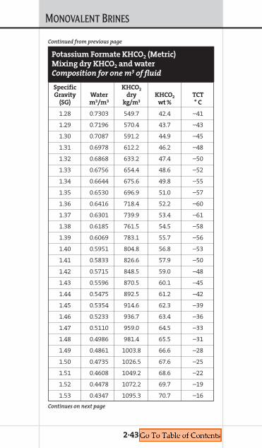
MONOVALENT BRINES
2·43
Specific KHCO2
Gravity Water dry KHCO2 TCT(SG) m3/m3 kg/m3 wt % ° C
1.28 0.7303 549.7 42.4 –41
1.29 0.7196 570.4 43.7 –43
1.30 0.7087 591.2 44.9 –45
1.31 0.6978 612.2 46.2 –48
1.32 0.6868 633.2 47.4 –50
1.33 0.6756 654.4 48.6 –52
1.34 0.6644 675.6 49.8 –55
1.35 0.6530 696.9 51.0 –57
1.36 0.6416 718.4 52.2 –60
1.37 0.6301 739.9 53.4 –61
1.38 0.6185 761.5 54.5 –58
1.39 0.6069 783.1 55.7 –56
1.40 0.5951 804.8 56.8 –53
1.41 0.5833 826.6 57.9 –50
1.42 0.5715 848.5 59.0 –48
1.43 0.5596 870.5 60.1 –45
1.44 0.5475 892.5 61.2 –42
1.45 0.5354 914.6 62.3 –39
1.46 0.5233 936.7 63.4 –36
1.47 0.5110 959.0 64.5 –33
1.48 0.4986 981.4 65.5 –31
1.49 0.4861 1003.8 66.6 –28
1.50 0.4735 1026.5 67.6 –25
1.51 0.4608 1049.2 68.6 –22
1.52 0.4478 1072.2 69.7 –19
1.53 0.4347 1095.3 70.7 –16
Potassium Formate KHCO2 (Metric)
Mixing dry KHCO2 and water
Composition for one m3 of fluid
Continues on next page
Continued from previous page
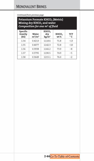
MONOVALENT BRINES
2·44
Specific KHCO2
Gravity Water dry KHCO2 TCT(SG) m3/m3 kg/m3 wt % ° C
1.54 0.4213 1118.6 71.8 –13
1.55 0.4077 1142.3 72.8 –10
1.56 0.3938 1166.2 73.9 –8
1.57 0.3795 1190.5 74.9 –5
1.58 0.3649 1215.1 76.0 –2
Potassium Formate KHCO2 (Metric)
Mixing dry KHCO2 and water
Composition for one m3 of fluid
Continued from previous page
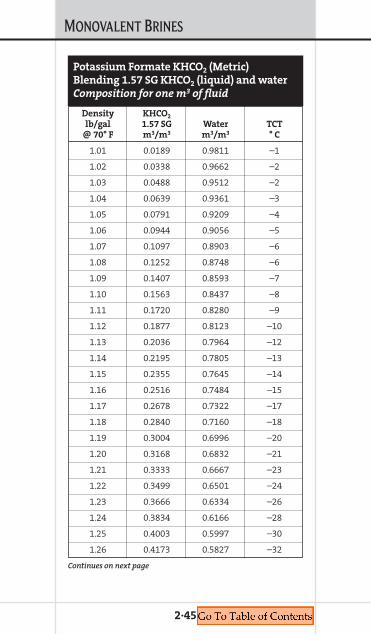
MONOVALENT BRINES
2·45
Potassium Formate KHCO2 (Metric)
Blending 1.57 SG KHCO2 (liquid) and water
Composition for one m3 of fluid
Density KHCO2
lb/gal 1.57 SG Water TCT@ 70° F m3/m3 m3/m3 ° C
1.01 0.0189 0.9811 –1
1.02 0.0338 0.9662 –2
1.03 0.0488 0.9512 –2
1.04 0.0639 0.9361 –3
1.05 0.0791 0.9209 –4
1.06 0.0944 0.9056 –5
1.07 0.1097 0.8903 –6
1.08 0.1252 0.8748 –6
1.09 0.1407 0.8593 –7
1.10 0.1563 0.8437 –8
1.11 0.1720 0.8280 –9
1.12 0.1877 0.8123 –10
1.13 0.2036 0.7964 –12
1.14 0.2195 0.7805 –13
1.15 0.2355 0.7645 –14
1.16 0.2516 0.7484 –15
1.17 0.2678 0.7322 –17
1.18 0.2840 0.7160 –18
1.19 0.3004 0.6996 –20
1.20 0.3168 0.6832 –21
1.21 0.3333 0.6667 –23
1.22 0.3499 0.6501 –24
1.23 0.3666 0.6334 –26
1.24 0.3834 0.6166 –28
1.25 0.4003 0.5997 –30
1.26 0.4173 0.5827 –32
Continues on next page

MONOVALENT BRINES
2·46
Potassium Formate KHCO2 (Metric)
Blending 1.57 SG KHCO2 (liquid) and water
Composition for one m3 of fluid
Density KHCO2
lb/gal 1.57 SG Water TCT@ 70° F m3/m3 m3/m3 ° C
1.27 0.4343 0.5657 –34
1.28 0.4515 0.5485 –36
1.29 0.4687 0.5313 –39
1.30 0.4860 0.5140 –41
1.31 0.5035 0.4965 –43
1.32 0.5210 0.4790 –46
1.33 0.5386 0.4614 –49
1.34 0.5563 0.4437 –51
1.35 0.5741 0.4259 –54
1.36 0.5919 0.4081 –57
1.37 0.6099 0.3901 –58
1.38 0.6280 0.3720 –54
1.39 0.6462 0.3538 –51
1.40 0.6644 0.3356 –47
1.41 0.6828 0.3172 –52
1.42 0.7012 0.2988 –49
1.43 0.7198 0.2802 –47
1.44 0.7385 0.2615 –44
1.45 0.7572 0.2428 –41
1.46 0.7761 0.2239 –38
1.47 0.7950 0.2050 –36
1.48 0.8141 0.1859 –33
1.49 0.8332 0.1668 –30
1.50 0.8525 0.1475 –27
1.51 0.8718 0.1282 –24
Continues on next page
Continued from previous page

MONOVALENT BRINES
2·47
Potassium Formate KHCO2 (Metric)
Blending 1.57 SG KHCO2 (liquid) and water
Composition for one m3 of fluid
Density KHCO2
lb/gal 1.57 SG Water TCT@ 70° F m3/m3 m3/m3 ° C
1.52 0.8913 0.1087 –22
1.53 0.9109 0.0891 –19
1.54 0.9305 0.0695 –16
1.55 0.9503 0.0497 –13
1.56 0.9702 0.0298 –10
1.57 0.9901 0.0099 –8
Continued from previous page

MONOVALENT BRINES
2·48
Specific %Gravity lb NH4CL bbl NH4CL
Density (SG) per bbl Water/ Weight/lb/gal at 60° F Brine bbl Brine Weight
8.4 1.007 7 0.990 1.98
8.45 1.013 10.5 0.981 3.0
8.5 1.020 19 0.969 5.3
8.6 1.031 30 0.940 8.4
8.7 1.044 42 0.919 11.5
8.8 1.055 53 0.900 14.4
8.9 1.068 65 0.881 17.4
9.0 1.079 77 0.860 20.4
9.1 1.128 88 0.840 23.0
9.2 1.103 100 0.819 25.8
9.3 1.139 135 0.750 33.9
NH4Cl Brine (U.S.)
Composition for one barrel of fluid
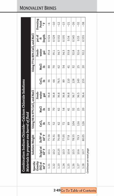
MONOVALENT BRINES
2·49
Sp
eci
fic
So
luti
on
We
igh
tU
sin
g 9
4 t
o 9
7%
Ca
Cl 2
an
d N
aC
lU
sin
g 7
7 t
o 8
0%
Ca
Cl 2
an
d N
aC
l
Gra
vit
yF
resh
-F
resh
-p
si o
fF
ree
zin
g(S
G)
at
lb/g
al
at
lb/f
t3a
tC
aC
l 2N
aC
lw
ate
rC
aC
l 2N
aC
lw
ate
rft
Po
int
60
° F
60
° F
60
° F
lblb
ga
llb
lbg
al
De
pth
° F
1.21
10.1
75.5
629
8836
.836
8835
.80.
524
–4
1.22
10.2
76.3
152
7036
.864
7035
.10.
529
–10
1.23
10.2
576
.68
6262
36.8
76.5
6234
.70.
532
–12
1.24
10.3
77.0
572
5436
.889
5434
.30.
535
–15
1.25
10.4
77.8
8941
36.8
110
4133
.80.
54–2
1
1.26
10.5
78.5
510
432
36.7
128
3232
.80.
545
–26
1.27
10.6
79.3
116
2536
.514
325
32.6
0.55
–32
1.28
10.7
80.0
512
620
36.4
155
2032
.20.
555
–38
Co
mb
ina
tio
n S
od
ium
Ch
lori
de
–C
alc
ium
Ch
lori
de
So
luti
on
s
Ma
teri
als
to
pre
pa
re o
ne
ba
rre
l o
f fl
uid
Con
tin
ues
on
nex
t p
age

MONOVALENT BRINES
2·50
Con
tin
ued
from
pre
viou
s p
age
Sp
eci
fic
So
luti
on
We
igh
tU
sin
g 9
4 t
o 9
7%
Ca
Cl 2
an
d N
aC
lU
sin
g 7
7 t
o 8
0%
Ca
Cl 2
an
d N
aC
l
Gra
vit
yF
resh
-F
resh
-p
si o
fF
ree
zin
g(S
G)
at
lb/g
al
at
lb/f
t3a
tC
aC
l 2N
aC
lw
ate
rC
aC
l 2N
aC
lw
ate
rft
Po
int
60
° F
60
° F
60
° F
lblb
ga
llb
lbg
al
De
pth
° F
1.29
10.7
580
.42
131
1836
.316
118
32.0
0.55
8–4
0
1.30
10.8
80.7
913
516
36.3
167
1631
.70.
561
–42
1.31
10.9
81.5
414
413
36.2
178
1331
.30.
566
–24
1.32
1182
.29
151
1036
.118
610
31.0
0.57
1–1
2
1.33
11.1
83.0
415
98
3619
68
30.6
0.57
60
Co
mb
ina
tio
n S
od
ium
Ch
lori
de
–C
alc
ium
Ch
lori
de
So
luti
on
s
Ma
teri
als
to
pre
pa
re o
ne
ba
rre
l o
f fl
uid
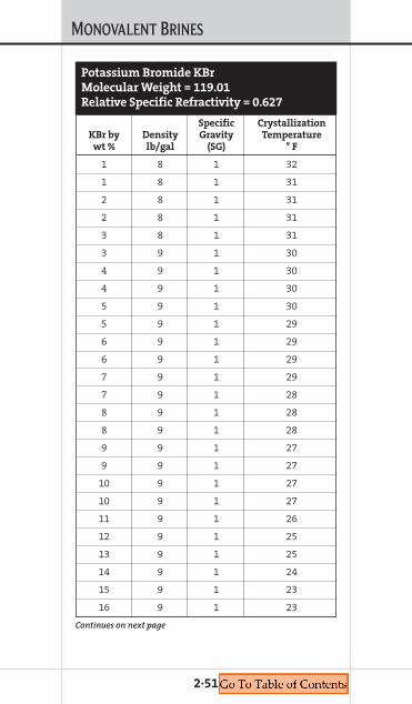
MONOVALENT BRINES
2·51
Potassium Bromide KBr
Molecular Weight = 119.01
Relative Specific Refractivity = 0.627
Specific CrystallizationKBr by Density Gravity Temperaturewt % lb/gal (SG) ° F
1 8 1 32
1 8 1 31
2 8 1 31
2 8 1 31
3 8 1 31
3 9 1 30
4 9 1 30
4 9 1 30
5 9 1 30
5 9 1 29
6 9 1 29
6 9 1 29
7 9 1 29
7 9 1 28
8 9 1 28
8 9 1 28
9 9 1 27
9 9 1 27
10 9 1 27
10 9 1 27
11 9 1 26
12 9 1 25
13 9 1 25
14 9 1 24
15 9 1 23
16 9 1 23
Continues on next page
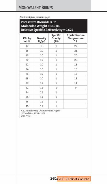
MONOVALENT BRINES
2·52
Specific CrystallizationKBr by Density Gravity Temperaturewt % lb/gal (SG) ° F
17 9 1 22
18 10 1 21
19 10 1 20
20 10 1 20
22 10 1 18
24 10 1 16
26 10 1 15
28 10 1 13
30 11 1 11
32 11 1 9
34 11 1
36 11 1
38 11 1
40 11 1
CRC Handbook of Chemistry and Physics57th edition 1976–1977CRC Press
Continued from previous page
Potassium Bromide KBr
Molecular Weight = 119.01
Relative Specific Refractivity = 0.627

MONOVALENT BRINES
2·53
SodiumDensity Water Acetate Sodium Acetate TCTlb/gal bbl/bbl lb/bbl mg/L mg/L ° F
8.3 0.9976 1.75 1,401 3,598 32
8.4 0.9901 7.06 5,647 14,502 31
8.5 0.9739 17.92 14,330 36,785 29
8.6 0.9627 25.33 20,250 52,009 27
8.7 0.9517 32.90 26,300 67,556 24
8.8 0.9350 44.56 35,630 91,509 22
8.9 0.9234 52.54 42,010 107,883 19
9.0 0.9113 60.67 48,510 124,583 15
9.1 0.8987 68.95 55,130 141,592 12
9.2 0.8856 77.38 61,870 158,904 7
9.3 0.8720 85.96 68,730 176,513 3
9.4 0.8579 94.69 75,710 194,436 –1
9.5 0.8434 103.57 82,810 212,674 22
9.6 0.8286 112.62 90,050 231,263 28
9.7 0.8136 121.87 97,440 250,264 42
Sodium Acetate NaH3C2O2 (U.S.)
Mixing dry Sodium Acetate and water
Composition for one barrel of fluid
Chapter 3EXAMPLE CALCULATIONS
COMPLETION FLUIDSMANUAL
3. EXAM
PLECALCULATIONS

EXAMPLE CALCULATIONS
Increase the Density of a Single-SaltSystem Using the Same Dry SaltIn order to increase the density of a single saltwith the same dry salt, you must have blendcharts that contain the pounds per barrel of saltand the water fraction. These equations applyfor any single salt as long as it is the same as thebase brine.
Do = Density of the original fluid in lb/galDf = Density of the final fluid in lb/gal
Wo = Water fraction of the original fluidWf = Water fraction of the final fluid
So = Salt of the original fluid in poundsSf = Salt of the final fluid in pounds
Vo = Volume of the original fluid in bblVf = Volume of the final fluid in bbl
Pounds of salt to add = ((Wo * Sf/Wf) – So) * Vo
Volume gained = (Wo/Wf * Vo) – Vo
Example using CaCl2 Table on page 1·5:
To weigh up 100 bbl of 9.0 lb/gal CaCl2 to 9.9 lb/gal CaCl2 with dry CaCl2
Pounds of salt to add = ((Wo * Sf/Wf) – So) * Vo
Pounds of salt to add = (0.9755 * 89.4/0.9346) –
37.2) * 100
Pounds of salt to add = 5,611 lb
Volume gained = (Wo/Wf * Vo) – Vo
Volume gained = (0.9755/0.9346 * 100) – 100
Volume gained = 4.4 bbl
3·1

EXAMPLE CALCULATIONS
Increase the Density of a Two-Salt System Using Dry BromideIn order to increase the density of a two-saltsystem with the dry bromide, you must haveblend charts that contain the pounds per barrelof salt and the water fraction. These equationsapply to both NaBr and CaBr2 additions. If usingNaBr, substitute NaBr in the following equa-tions for CaBr2.
Do = Density of the original fluid in lb/galDf = Density of the final fluid in lb/gal
Wo = Water fraction of the original fluidWf = Water fraction of the final fluid
Co = Chloride salt of the original fluidCf = Chloride salt of the final fluid
Bo = Bromide salt of the original fluidBf = Bromide salt of the final fluid
Vo = Volume of the original fluid in bblVf = Volume of the final fluid in bbl
Wa = Water to add to start the blend (bbl)Ba = Pounds of bromide salt to add
Vf = (Co/Cf) * Vo
Wa = Vo(Co * Wf/Cf) – Vo(Wo)
Ba = Vo(Co * Bf/Cf) – Vo(Bo)
3·2

EXAMPLE CALCULATIONS
Example:
To weigh up 100 bbl of 12.0 lb/gal CaBr2/CaCl2
to 12.5 lb/gal CaBr2/CaCl2 with dry CaBr2
Vf = Co/Cf * Vo
Vf = 194.1/183.7 * 100
Vf = 105.7
Wa = Vo(Co * Wf/Cf) – Vo(Wo)
Wa = 100(194.1 * 0.768/183.7) – 100(0.793)
Wa = 1.8 bbl
Ba = Vo(Co * Bf/Cf) – Vo(Bo)
Ba = 100(183.7 * 72.6/183.7) – 100(32.3)
Ba = 4,030 lb
3·3

EXAMPLE CALCULATIONS
How to Calculate Weight % SaltTo calculate the % by weight salt in a brinesystem, one must know the density and theamount of salt (lb/bbl) in the brine.
% by weight = Pounds of salt in the brinesystem/(density in lb/gal * 42)
For example:
To calculate the % by weight of an 8.5 lb/gal KCl.
% by weight = 11.6/(8.5 lb/gal * 42)
% by weight = 3.2% or ~3% KCl (by weight)
To convert % by weight or weight percent toparts per million (ppm) multiply by 10,000.
3% KCl (by weight or w/w) = 3 * 10,000 = 30,000 ppm
To convert parts per million (ppm) to milligramper liter (mg/L), divide ppm by specific gravityof the fluid.
To convert density into specific gravity, divideby density of water @ 70° F = 8.5/8.345
= 1.019
30,000 ppm = 30,000/1.019 = 29,452 mg/L
3·4
Chapter 4QHSE
COMPLETION FLUIDSMANUAL
4. QHSE
QHSE
4·1
Completion Fluids Safe Handling GuideThe HazardsLike all chemicals, oilfield completion fluids(brines) can be hazardous to your health if nothandled properly. Brines have unique chemicalproperties and consequently must be handleddifferently from conventional drilling muds.
Brines are salts dissolved in water. Brinesused in oil and gas well completions are for-mulated with sodium chloride (NaCl, tablesalt), potassium chloride (KCl), sodium bromide(NaBr), calcium chloride (CaCl2), calcium bro-mide (CaBr2), zinc bromide (ZnBr2), sodiumformate (NaHCO2), and potassium formate(KHCO2). Brines may also contain various vis-cosifiers, corrosion inhibitors and other addi-tives for special applications.
Water weighs 8.3 lb/gal (1 SG) while oilfieldbrines can weigh from 8.4 to 20 lb/gal (1.01 to2.4 SG), depending upon the amount and typeof salt added. Generally, as brines get heavierthey are more dangerous to handle and aremore damaging to equipment and theenvironment.
Hazardous Properties of Brines• Acidity (pH) — Zinc brines are acidic. • Absorption of water — Heavy brines contain
so much salt that they will absorb water fromtheir surroundings.
• Chemical reactions — Toxic chlorine orbromine gas can be released from brines.There are two circumstances where thiscould occur:1. When brines are exposed to the extremely
high temperatures of a fire, or

QHSE
2. When brines are exposed to strong oxidizingagents used to break viscosifiers.
• Toxicity — Brines can be toxic if large quanti-ties are swallowed. This is usually not a signifi-cant route of exposure at the rigsite.
Mixing Salts• Dry sodium/potassium/ammonium chloride
added to water reduces solution temperaturevery slightly
• Dry sodium/potassium bromide added towater raises solution temperature very slightly
• Dry calcium chloride/bromide added to waterraises solution temperature significantly – Temperature rise depends on rate of addition
• Addition of dry CaCl2 or CaBr2 can boil water
Effects of Exposure• Skin contact — The acidity and/or the ten-
dency of brines to absorb water from theirsurroundings means that they can be quiteirritating or even corrosive to the skin. The irri-tating effect of brines is usually delayed; youmay not feel anything for several minutes oreven hours after exposure.
• Eye contact — Brines are immediately andseverely irritating to the eyes. Permanent eyedamage may result from even short exposureto heavy brines. Wash eyes for at least 15 minafter exposure and get medical attention.
• Inhalation — Inhalation of brine mist or spraycan be irritating to the mucous membranes ofthe nose, mouth and throat.
• Ingestion — Swallowing brine may causenausea, vomiting and diarrhea in addition toirritation of the mucous membranes of thegastrointestinal tract. Swallowing large quan-tities may cause more serious toxic effects,
4·2

QHSE
depending on the density of the brine andthe additives that it contains.
DO NOT INDUCE VOMITING WHEN ZINC
BROMIDE BRINES ARE INJESTED.
Protecting Yourself
• Read and follow the instructions on the MSDS
Always have the Material Safety Data Sheets(MSDS) available on location for all chemicalsthat you handle. Read and follow all instruc-tions on the MSDS.
• Avoid exposure
Avoiding exposure to brines is always the bestway to protect yourself. However, this is notalways possible on the job. Whenever expo-sure is possible use the equipment, proceduresand precautions outlined below.
• Use the correct Personal Protective
Equipment (PPE)
The following special equipment is necessaryfor handling brines:
Eyes — Wear chemical splash gogglesdesigned to seal against the skin aroundboth eyes and give protection against splashesfrom any angle. A full face shield may be usedin addition to goggles to protect the face.
Body — Wear slicker suits in areas whereexposure is likely. Slicker suits are hot andinterfere with the body's natural cooling,therefore, a slower work pace or rotatingworkers may be necessary. Rubber or plasticaprons may be worn for some jobs, such ascarrying sacks. These are more comfortablethan slicker suits but do not give as muchprotection.
4·3

QHSE
Hands — Wear leak-proof gloves made ofnatural or synthetic-rubber material. Glovecuffs should be worn inside of slicker suitsleeves to prevent brine from running off ofsleeves into gloves. For some jobs it may benecessary to seal sleeves over glove cuffsusing tape to prevent brine from running intosleeves when hands are raised. Cloth glovesmay be worn over rubber gloves to provide abetter grip and protect the rubber gloves fromtearing. Do not use leather gloves.
Feet — Wear leak-proof rubber steel-toe boots.Do not use leather boots.
Respiratory — Use a NIOSH-approved P95half-mask disposable or reusable particulatemask for mist/aerosol. All respiratory protec-tion equipment should be used within a com-prehensive respiratory protection programthat meets the requirements of 29 CFR1910.134 (OSHA Respiratory ProtectionStandard) or local equivalent.
• Practice good skin care
Dermatitis, or skin irritation, is a commonproblem when handling brines. The following3-step program is designed to help you pre-vent dermatitis:
Protection — Before contact with brines applya barrier cream to areas that are not easilycovered by some other form of PPE. Use a bar-rier cream specifically designed to protectagainst water-based hazards. Barrier creamsshould be used in addition to the PPE men-tioned above, not as a substitute for it.
4·4
QHSE
Cleaning — Wash frequently; use hand soap,not harsh industrial cleaners.
Reconditioning — Contact with brines andfrequent washing of the skin can result inloss of the skin's natural oils and moisture.To prevent dry, chaffed, and irritated skin,apply a reconditioning skin lotion after workand as needed.
Over-the-counter hydrocortisone creammay be used to relieve minor skin irritation.Follow instructions and precautions providedby the manufacturer. If left untreated minor
skin irritation can progress rapidly, resultingin intense itching and blisters which canbecome infected. Cases of severe dermatitis,especially if infection is suspected, should bereferred to a doctor immediately.
• Safety equipment
Emergency eye washes and showers shouldbe installed and easily accessible in all areaswhere brines are used, especially on the rigfloor, shaker area and mud pits. Eye washesand showers should be plainly marked withsigns and workers should be trained in theirlocation and proper use.
• Rigsite precautions
Use pipe wipers when pulling pipe. Keep thepipe wiper below waist level so that brine willnot splash into workers’ faces.
Brines are slippery. Use non-slip surfaceson the rig floor, stairs and decks.
Rinse off tools periodically to provide abetter grip and prevent brine from beingtransferred to clothing.
4·5
QHSE
Make sure that brine storage containersand seals are strong enough to hold the brinewithout rupturing or leaking. Heavy-dutytanks should be used for brines weighing over13.5 lb/gal (1.62 SG).
Environmental IssuesThe Comprehensive Environmental Response,Compensation and Liability Act (CERCLA) andThe Federal Water Pollution Control Act (CleanWater Act) list zinc bromide as a hazardoussubstance with a Reportable Quantity (RQ) of1,000 lb (453.6 kg).
Brines may be toxic to aquatic plants andanimal life. Care should be taken to preventbrines from entering waterways. ContactM-I SWACO Environmental Affairs for moreinformation.
North SeaUnder the environmental regulations govern-ing offshore operations in the North Sea, allcompletion brines — with the exception of zincbromide — are considered acceptable for dis-charge. This includes sodium, potassium andcesium formate. Completion brines containingzinc bromide brines may still be used in excep-tional circumstances, with the prior approvalof the government environmental body respon-sible for the geographical region in which theoperation will take place.
4·6

Chapter 5TEMPERATURE AND PRESSURE
COMPLETION FLUIDSMANUAL
5.TEM
PERATUREAND
PRESSURE

TEMPERATURE AND PRESSURE
Temperature and Pressure Effectson Completion FluidCompletion fluids exhibit the typical volumetricresponse to temperature and pressure, i.e.,expanding with increasing temperature andcompressing with increasing pressure. In ashallow water or land-based wellbore, theexpansion of a completion fluid with temper-ature produces a more pronounced affecton volume than does pressure. This overallincrease in volume results in a fluid of lowerdensity at the bottom of the well than at thesurface. In deepwater environments however,the depth of cold water will impact the expan-sion/compression relationship such that thefluid at the mud line is heavier than that atthe surface. The combination of hydrostaticpressure and cold temperature can have cata-strophic effects unless the fluid is properly for-mulated to account for this environment.
Phase DiagramsTrue Crystallization Temperature (TCT) isthat temperature at which the brine solutionis fully saturated with respect to the least solu-ble salt. Figure 5.1 represents the TCT test resultsof an example CaCl2-CaBr2 completion brine.Included in the diagram is the first crystal toappear (FCTA) and the last crystal to dissolve(LCTD). Figure 5.2 presents the phase diagram(TCT v. Temperature) for various common com-pletion fluids. Crystallization of the fluid as aresult of hydrostatic pressure is referred to asPressurized Crystallization Temperature (PCT).Figure 5.3 shows the impact of pressure on the
5·1
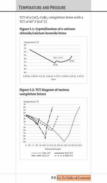
TEMPERATURE AND PRESSURE
TCT of a CaCl2-CaBr2 completion brine with aTCT of 40° F (4.4° C).
5·2
80
75
70
65
60
55
50
45
40
Temperature (° F)
Time
6:05:46 6:08:38 6:11:31 6:14:24 6:17:17 6:20:10 6:23:02 6:25:55
TCT = 57° F
FCTA
LCTD
g
Figure 5.1: Crystallization of a calcium
chloride/calcium bromide brine
70
60
50
40
30
20
10
0
-10
-20
-30
-40
-50
-60
Temperature (° F)
Density (lbm/gal)
CaBr2 TCTCaCl2 CT
NaCl TCTNaBr TCT
8 8.5 9 9.5 10 10.5 11 11.5 12 12.5 13 13.5 14 14.5 15 15.3
Figure 5.2: TCT diagram of various
completion brines

TEMPERATURE AND PRESSURE
Hydrate SuppressionGas hydrates are a concern when working withaqueous fluids in deepwater. They can occurduring critical phases of deepwater completion(displacement, perforating, subsea BOP tests,well tests, flow back, etc.), leading to significantdowntime if not suppressed in the fluid design.Hydrate formation can be prevented by reduc-ing the gas-water thermodynamic equilibriumpoint. Dissolved salts, glycols and alcohols areexamples of substances that perform this func-tion. However, in most circumstances fluidproperties such as density will limit the optionsavailable. For example, below about 10.5 lb/gal(1.26 SG), calcium chloride is unable to preventhydrate formation at a pressure of 10,000 psi(689 bar) and 40° F (4.4° C). If a low-densitywater-based formulation is required, oxy-genated solvents such as ethylene glycol,propylene glycol, methanol, etc. have shown
5·3
60
55
50
45
40
35
30
25
TCT (° F)
Pressure (psi)
0 5,000 10,000 15,000
Figure 5.3: Effect of pressure on TCT of a 40° F
(4.4° C) TCT CaCl2-CaBr2 brine
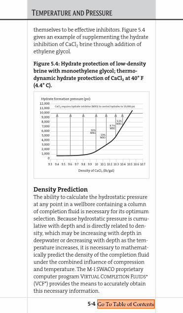
TEMPERATURE AND PRESSURE
5·4
themselves to be effective inhibitors. Figure 5.4gives an example of supplementing the hydrateinhibition of CaCl2 brine through addition ofethylene glycol.
Density PredictionThe ability to calculate the hydrostatic pressureat any point in a wellbore containing a columnof completion fluid is necessary for its optimumselection. Because hydrostatic pressure is cumu-lative with depth and is directly related to den-sity, which may be increasing with depth indeepwater or decreasing with depth as the tem-perature increases, it is necessary to mathemat-ically predict the density of the completion fluidunder the combined influence of compressionand temperature. The M-I SWACO proprietarycomputer program VIRTUAL COMPLETION FLUIDS*(VCF*) provides the means to accurately obtainthis necessary information.
12,00011,00010,000
9,0008,0007,0006,0005,0004,0003,0002,0001,000
0
Hydrate formation pressure (psi)
Density of CaCl2 (lb/gal)
9.3 9.4 9.5 9.6 9.7 9.8 9.9 10 10.1 10.2 10.3 10.4 10.5 10.6 10.7
CaCl2 requires hydrate inhibitor (MEG) to control hydrates to 10,000 psi
30%MEG
19%MEG
8.7%MEG
5.3%MEG
Figure 5.4: Hydrate protection of low-density
brine with monoethylene glycol; thermo-
dynamic hydrate protection of CaCl2 at 40° F
(4.4° C).
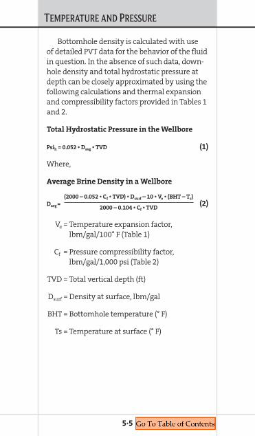
TEMPERATURE AND PRESSURE
Bottomhole density is calculated with useof detailed PVT data for the behavior of the fluidin question. In the absence of such data, down-hole density and total hydrostatic pressure atdepth can be closely approximated by using thefollowing calculations and thermal expansionand compressibility factors provided in Tables 1and 2.
Total Hydrostatic Pressure in the Wellbore
Psih = 0.052 * Davg * TVD (1)
Where,
Average Brine Density in a Wellbore
(2000 – 0.052 * Cf * TVD) * Dsurf – 10 * Ve * (BHT – Ts)
Davg = (2)2000 – 0.104 * Cf * TVD
Ve = Temperature expansion factor,lbm/gal/100° F (Table 1)
Cf = Pressure compressibility factor,lbm/gal/1,000 psi (Table 2)
TVD = Total vertical depth (ft)
Dsurf = Density at surface, lbm/gal
BHT = Bottomhole temperature (° F)
Ts = Temperature at surface (° F)
5·5

TEMPERATURE AND PRESSURE
5·6
Table 1. Expansibility of Brines at 12,000 psi
from 76° to 198° F
Brine Density Ve
Type (lbm/gal) (lbm/gal/100° F)
NaCl 9.42 0.24
CaCl2 11.45 0.27
NaBr 12.48 0.33
CaBr2 14.13 0.33
ZnBr2/CaBr2/CaCl2 16.01 0.36
ZnBr2/CaBr2 19.27 0.48
Table 2. Compressibility of Brines at
198° F from 2,000 to 12,000 psi
Brine Density Cf
Type (lbm/gal) (lbm/gal/1,000 psi)
NaCl 9.49 0.019
CaCl2 11.45 0.017
NaBr 12.48 0.021
CaBr2 14.30 0.022
ZnBr2/CaBr2/CaCl2 16.01 0.022
ZnBr2/CaBr2 19.27 0.031

Chapter 6TESTING PROCEDURES
COMPLETION FLUIDSMANUAL
6. TESTING
PROCEDURES

TESTING PROCEDURES
6·1
Marsh Funnel ViscosityScope and LimitationsThe Marsh funnel is used for routine field meas-urement of viscosity. It provides a quick andeasy procedure for monitoring viscosity of neatbrines, viscosified brines, spacers and reservoirdrill-in fluids. Changes in Marsh funnel vis-cosity can indicate that there may be polymerdegradation or contamination by solids orchemicals. Further testing or fluid-componentinformation is usually required to determinethe cause of the viscosity change.
References• API RP 13B-1, 3rd Edition, December 2003• M-I Drilling Fluids Engineering Manual, v.1.0,
M-I L.L.C. (July 1998)
Safety• Wear safety glasses• Gloves are required when handling corrosive
or hazardous fluids
Equipment and Chemicals Required• Marsh funnel• 1-qt receiving cup• Stopwatch • Thermometer
Calibration Procedure1. Obtain 1,500 mL freshwater and check
temperature.2. Adjust water temperature to 75 ±5° F
(24 ±2.5° C).3. Inspect Marsh funnel to make certain it is
not dirty or damaged.

TESTING PROCEDURES
4. Fill Marsh funnel to the bottom of the screenwith freshwater, covering orifice with fingerto prevent fluid from escaping.
5. Place filled Marsh funnel in upright positionover the 1-qt receiving cup.
6. Start stopwatch and remove finger fromfunnel orifice at the same time.
7. Stop stopwatch when fluid level in receivingcup reaches the 1-qt line.
8. One qt of water should take 26 ±0.5 sec.If your results vary from this time, repeatcalibration process. Take special care to cleanfunnel properly, and to remove finger fromfunnel orifice and start stopwatch at thesame time.
Procedure1. Obtain 1,500 mL sample and check
temperature. Record fluid temperature.2. Pour freshly collected sample into clean and
dry Marsh funnel until the fluid level reachesthe bottom of the screen, covering funnelorifice to prevent fluid from escaping.
3. Simultaneously remove finger from funnelorifice and start stopwatch.
4. Report result to the nearest second as Marshfunnel viscosity.
Fann 35 Viscosity: PV, YP, AV Gel StrengthsScope and LimitationsThe Fann 35 viscometer is used for measure-ment of viscosity, including PV, YP and 10-secand 10-min gel strengths. Additional usefulinformation can be obtained using the Fann 35for characterizing fluids, but these are the
6·2
TESTING PROCEDURES
primary values described in this procedure.These values can assist in evaluating carryingcapacity and quality of viscosified brine fluids,displacement spacers, fluid-loss pills and res-ervoir drill-in fluids. One can also detect pos-sible presence of polymer in clear brine fluidsthat can impact filterability and formationdamage potential.
References• API RP 13B-1, 3rd Edition, December 2003• M-I Drilling Fluids Engineering Manual, v.1.0,
M-I L.L.C. (July 1998)• VG Meter Calibration, Job Instructions Manual,
Western Hemisphere ISO Home Page, current version found at midhouhq-www01.corp.smith-intl.com
Safety• Wear safety glasses• Do not test fluids above 180° F (82° C), hollow
bob can explode when trapped moisturevaporizes. Use solid bob if higher temperaturetesting is necessary.
Equipment and Chemicals Required• Fann 35A or equivalent viscometer with
R1/B1/F1 configuration (standard rotor,bob and spring)
• Stopwatch • Thermometer• Calibration fluids
Calibration Calibration and repair of Fann 35 viscometersshould be performed by trained M-I SWACOpersonnel or outside vendors who are familiarwith the proper procedures.
6·3

TESTING PROCEDURES
Simple calibration checks can be performedby using special calibration fluids with viscosityversus temperature chart.
Calibration checks are quick and easy, andshould be performed regularly to ensure properequipment performance. 1. Select a viscosity standard near the viscosity
of fluids normally measured.2. Check that the zero RPM reading of the instru-
ment is 0 ± 0.5 dial readings.3. Measure temperature and viscosity at
600 RPM and 300 RPM.4. Compare Fann 35 reading at 300 RPM and
Fann 35 reading at 600 RPM divided by 2 tothe value shown for that temperature on thecalibration fluid chart.
5. These values should be ± 1.5 from thechart value.
Procedure for Apparent Viscosity,
Plastic Viscosity and Yield Point1. Mix sample to provide uniformity and
disrupt progressive gel structure.2. Pour sample into thermocup, place on
Fann 35 sample platform and raise untilfluid level is at the Fann 35 rotor-scribe line(above the two holes in the rotor).
3. Heat or cool sample to 120° F (49° C) whilerunning Fann 35 at 100 RPM. 100 RPM can beachieved by starting the motor in low speed(with switch down towards the back) and lift-ing red gear-shifter knob all the way up. Onlychange gears when the motor is running.
4. Once temperature has stabilized at 120° F(49° C), change speed to 600 RPM by depress-ing gear shifter knob all the way down withmotor still running, then switching the motor
6·4

TESTING PROCEDURES
to high speed by pushing the switch downand toward the front of the instrument.
5. Wait for a steady reading and record.6. Change speed to 300 RPM by switching the
motor back to low speed. Wait for a steadyvalue and record the 300 RPM value.
7. Plastic Viscosity (cP) = 600 reading – 300reading
8. Yield Point (lb/100 ft2) = 300 reading – PV9. Apparent Viscosity (cP) = 600 reading
2
Procedure for Gel Strength1. Maintaining the sample temperature at
120° F (49° C), stir sample at 600 RPM for10 sec.
2. Quickly adjust gear knob while motor is run-ning in preparation for taking 3 RPM reading.
3. Turn off viscometer and start stopwatch.4. After 10 sec have elapsed, turn the Fann 35
on to 3 RPM and watch dial reading increasethen fall off.
5. Record maximum value achieved as 10-secgel strength (lb/100 ft2).
6. Restir sample at 600 RPM for 10 sec.7. Quickly adjust gear knob while motor is run-
ning in preparation for taking 3 RPM reading.8. Turn off viscometer and start stopwatch.9. After 10 min have elapsed, turn the Fann 35
on to 3 RPM and watch dial reading increasethen fall off.
10. Record maximum value achieved as 10-mingel strength (lb/100 ft2).
6·5
TESTING PROCEDURES
TurbidityScope and LimitationsTurbidity is the measurement of light scatterusing an NTU meter. The value is reported inNephelometric Turbidity Units (NTU). This pro-cedure does not determine size or quantity ofinsoluble solids in brine.
References• API RP 13J, 3rd Edition, December 2003
Safety• Wear safety glasses
Equipment and Chemicals Required• Distilled or deionized water• NTU meter• Clean, dry sample cuvettes free from scratches
Procedure1. Turn on NTU meter.2. Insert standardizing cuvette into NTU meter
and calibrate, if necessary, by followingmanufacturer’s instructions.
3. Fill sample cuvette with brine to theappropriate level.
4. Clean outside of cuvette, then rinse withdistilled or deionized water.
5. Dry sample cuvette with lint-free cloth.6. Insert sample cuvette into NTU meter.7. Read NTU value after meter reading
has stabilized.
6·6

TESTING PROCEDURES
6·7
Total Suspended Solids Scope and LimitationsThis procedure quantifies insoluble solids inweight percent. Rinsing the filter with distilledor deionized water after filtration is importantwhen testing brines because soluble-solidscontent can contribute to erroneously highresults. Salt residue remaining on filter canalso contribute to long drying time becausethe salt is hygroscopic. A representative sampleis important, so unrepresentative trash, sticks,paper, etc. should be removed from samplebefore testing.
References• API RP 13J, 3rd Edition, December 2003
Safety• Wear safety glasses and chemically
resistant gloves
Equipment and Chemicals Required• Distilled or deionized water• Oven, set to 220° F ± 2° F (104° C ± 1° C)• Filters, 4.8 cm diameter, no organic binder• Membrane filter holder• 100 mL graduated cylinder• Balance, accurate to 5 places• Dessicator with appropriate dessicant• 20 mL wide tip pipette• Aluminum weighing pans
Procedure1. This test should be run in triplicate.2. Set up vacuum-filtration device and paper.
Place filter paper with rough side face-up.3. Filter 3 aliquots of 20 mL distilled or
deionized water.
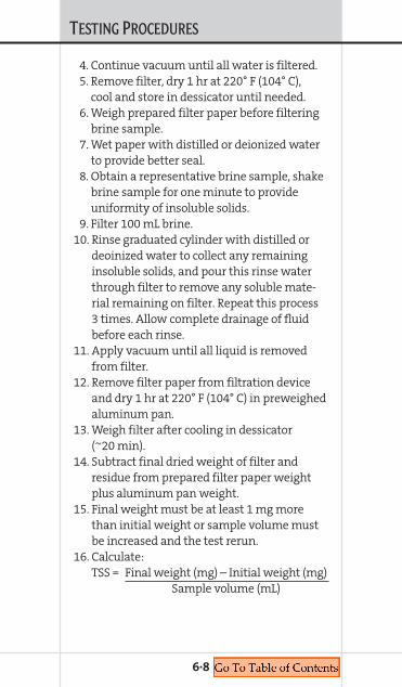
TESTING PROCEDURES
4. Continue vacuum until all water is filtered.5. Remove filter, dry 1 hr at 220° F (104° C),
cool and store in dessicator until needed.6. Weigh prepared filter paper before filtering
brine sample.7. Wet paper with distilled or deionized water
to provide better seal.8. Obtain a representative brine sample, shake
brine sample for one minute to provideuniformity of insoluble solids.
9. Filter 100 mL brine. 10. Rinse graduated cylinder with distilled or
deoinized water to collect any remaininginsoluble solids, and pour this rinse waterthrough filter to remove any soluble mate-rial remaining on filter. Repeat this process3 times. Allow complete drainage of fluidbefore each rinse.
11. Apply vacuum until all liquid is removedfrom filter.
12. Remove filter paper from filtration deviceand dry 1 hr at 220° F (104° C) in preweighedaluminum pan.
13. Weigh filter after cooling in dessicator(~20 min).
14. Subtract final dried weight of filter andresidue from prepared filter paper weightplus aluminum pan weight.
15. Final weight must be at least 1 mg morethan initial weight or sample volume mustbe increased and the test rerun.
16. Calculate:TSS = Final weight (mg) – Initial weight (mg)
Sample volume (mL)
6·8
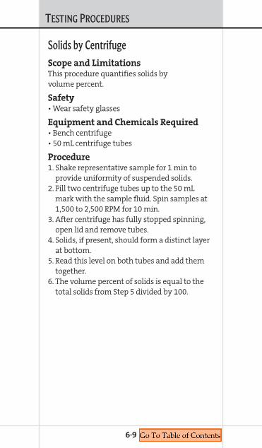
TESTING PROCEDURES
6·9
Solids by CentrifugeScope and LimitationsThis procedure quantifies solids byvolume percent.
Safety• Wear safety glasses
Equipment and Chemicals Required• Bench centrifuge • 50 mL centrifuge tubes
Procedure1. Shake representative sample for 1 min to
provide uniformity of suspended solids.2. Fill two centrifuge tubes up to the 50 mL
mark with the sample fluid. Spin samples at1,500 to 2,500 RPM for 10 min.
3. After centrifuge has fully stopped spinning,open lid and remove tubes.
4. Solids, if present, should form a distinct layerat bottom.
5. Read this level on both tubes and add themtogether.
6. The volume percent of solids is equal to thetotal solids from Step 5 divided by 100.
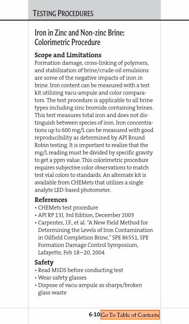
TESTING PROCEDURES
Iron in Zinc and Non-zinc Brine:Colorimetric ProcedureScope and LimitationsFormation damage, cross-linking of polymers,and stabilization of brine/crude-oil emulsionsare some of the negative impacts of iron inbrine. Iron content can be measured with a testkit utilizing vacu-ampule and color compara-tors. The test procedure is applicable to all brinetypes including zinc bromide containing brines.This test measures total iron and does not dis-tinguish between species of iron. Iron concentra-tions up to 600 mg/L can be measured with goodreproducibility as determined by API RoundRobin testing. It is important to realize that themg/L reading must be divided by specific gravityto get a ppm value. This colorimetric procedurerequires subjective color observations to matchtest vial colors to standards. An alternate kit isavailable from CHEMets that utilizes a singleanalyte LED-based photometer.
References• CHEMets test procedure• API RP 13J, 3rd Edition, December 2003• Carpenter, J.F., et al. “A New Field Method for
Determining the Levels of Iron Contaminationin Oilfield Completion Brine,” SPE 86551, SPEFormation Damage Control Symposium,Lafayette, Feb 18–20, 2004
Safety• Read MSDS before conducting test• Wear safety glasses• Dispose of vacu-ampule as sharps/broken
glass waste
6·10

TESTING PROCEDURES
Equipment and Chemicals RequiredComplete Test Kit (CHEMets catalog numberK-6002) contains:• Refill, 30 CHEMets ampules (R-6002)• Acidifier solution, six 70 mL bottles (A-6001)• Activator solution, six 20 mL bottles (A-6002)• Sample cup, 50 mL, package of six (A-0027)• Syringe, 1 mL, package of six (A-0027)• Comparator, 0–100 mg/L (C-6002)• Comparator, 100–1,000 (C-6012)
Procedure1. Mix sample to ensure sample uniformity,
but do not include non-suspended solids.2. Use 1 mL syringe to add 0.5 mL of sample to
the 50 mL sample cup. Remove any bubblesfrom syringe by tapping syringe with tippointing upward.
3. Using a different 1 mL syringe, add 1 mL ofacidifier solution to sample cup.
4. Add 5 drops activator solution. (Use 10 dropsif the sample has 2% + organic content, i.e.EGMBE.)
5. Swirl cup and wait 2 min.6. Fill sample cup to 50 mL with iron-free water
(distilled or deionized preferred).7. Screw cap onto sample cup and shake to
mix contents.8. Remove cap, and place ampule in sample
cup. Snap tip by pressing ampule against theside of the cup. The ampule will fill, but willcontain a small bubble of air to aid in mixing.
9. Invert ampule several times, allowing bubbleto travel from one end of the ampule to theother each time, in order to mix contents.
6·11

TESTING PROCEDURES
10. Using the appropriate comparator, deter-mine iron content by matching color to thatof one of the standards. A bright-white lightor sunlight is preferable to fluorescent light-ing for an accurate reading. If the color isbetween two color standards, make a con-centration estimate.a. To use low range comparator, place the
ampule flat end downward, into the centeropening in the comparator. Rotate com-parator until the closest match isobserved.
b. To use high-range comparator, placeampule comparator in a nearly horizontalposition. Place ampule between colorstandards, moving it along the compara-tor until the closest match is observed.
11. Divide mg/L reading by specific gravity toobtain ppm iron in sample.
pH of BrineScope and LimitationsThe pH of neat brine is measured using acombination glass electrode containing adouble-junction reference electrode and thecorresponding meter. This type of electrode isrecommended in API RP 13J, and is less sensi-tive to high salinity and solids content thanmost other pH probes. Measurement of pH onneat (undiluted) brine is more reproduciblethan 1:9 Brine:Water dilutions, and is the APIrecommended procedure. Although ISFETprobes are perceived as being sturdier, the useof ISFET probes may result in lower pH readings.pH is generally defined as the negative log ofH+ activity; however, this definition does not
6·12
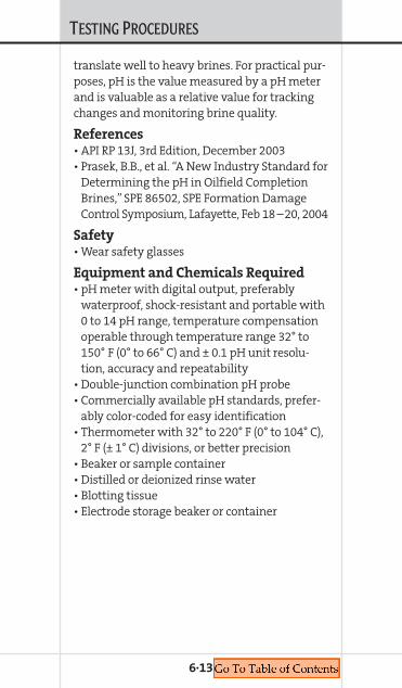
TESTING PROCEDURES
translate well to heavy brines. For practical pur-poses, pH is the value measured by a pH meterand is valuable as a relative value for trackingchanges and monitoring brine quality.
References• API RP 13J, 3rd Edition, December 2003• Prasek, B.B., et al. “A New Industry Standard for
Determining the pH in Oilfield CompletionBrines,” SPE 86502, SPE Formation DamageControl Symposium, Lafayette, Feb 18 –20, 2004
Safety• Wear safety glasses
Equipment and Chemicals Required• pH meter with digital output, preferably
waterproof, shock-resistant and portable with0 to 14 pH range, temperature compensationoperable through temperature range 32° to150° F (0° to 66° C) and ± 0.1 pH unit resolu-tion, accuracy and repeatability
• Double-junction combination pH probe• Commercially available pH standards, prefer-
ably color-coded for easy identification• Thermometer with 32° to 220° F (0° to 104° C),
2° F (± 1° C) divisions, or better precision• Beaker or sample container• Distilled or deionized rinse water• Blotting tissue• Electrode storage beaker or container
6·13

TESTING PROCEDURES
pH meters and electrodes conforming to API RP13J requirements are readily available throughseveral laboratory equipment and scientificsupply outlets.
Calibration Procedure and
Care of Electrode
pH meter calibration should be checkedprior to first use and at least every 8 hrs ofcontinuous use.
1. Before calibration, rinse electrode with dis-tilled or deionized water, and inspect elec-trode for breakage and formation ofprecipitation or polymer coating. Clean orreplace electrode if it does not pass inspection.
2. Follow probe manufacturer’s calibration pro-cedure using the pH 7.0 standard buffer andeither the pH 4.0 or pH 10.0 standard,depending on anticipated sample pH. Buffertemperature should be at 75° ± 5° F (24° ±±2.5° C) before calibrating. (The pH value onthe container is valid for 75° F (24° C), anda table of buffer values versus temperatureis required if calibration is conducted at adifferent temperature).
3. After calibration recheck pH 7.0 buffer, and ifthe meter does not read 7.0 ± 0.1 recalibratepH meter and check again.
6·14

TESTING PROCEDURES
Test Procedure1. Mix sample to ensure sample uniformity.2. Place sample in beaker or other appropriate
clean container. 3. Immerse thermometer to level recommended
by manufacturer. Read and record sampletemperature.
4. Sample temperature should be 75° ± 5° F (24°± 2.5° C), and the same temperature as buffersused in calibration. If sample temperatureis more than 20° F (–7° C) from calibrationtemperature, temperature compensation isrequired. pH values are sensitive to temper-ature differences in highly acidic or highlybasic solutions.
5. Place electrode into sample and stir gently,allowing pH reading to stabilize. This usuallytakes less than 2 min. pH probe should not beleft in brine for over 5 min.
6. Read and record pH reading to the nearest± 0.1 pH unit.
7. Rinse pH probe using distilled or deionizedwater.
8. Return probe to storage container.
Important Considerations for pH Meter
Calibration and pH Measurement• Calibration should be checked more frequently
than every 8 hr if probe is getting older or iftesting samples with high polymer or claycontent, low pH (< 2), high pH (> 10), oilor zinc-containing brines
• Fresh pH buffers should be used every day• pH probes can often be brought back to good
performance by reconditioning including
6·15
TESTING PROCEDURES
soaking 10 min in 0.1 M HCl, 10 min in 0.1MNaOH, then recalibrating meter
• Do not allow probe to go dry. Store in pH 4buffer solution or as recommended by probemanufacturer.
• It is good practice to keep a backup electrodeon hand, and to replace electrodes at leastevery 6 months (or as recommended bymanufacturer)
• If pH measurement is erratic (especially if itstabilizes when stirring is discontinued), if pHstabilization is slow with non-zinc brine, or ifre-calibration is required on increasingly fre-quent basis imminent probe failure is likely.Attempt reconditioning probe, and obtain areplacement probe before failure occurs.
Crystallization Point DeterminationScope and LimitationsThe crystallization temperature of brine isthe temperature at which the brine willform solids, either salt crystals or ice (givenenough time and nucleating conditions). TrueCrystallization Temperature (TCT) is the valuereported. Precipitation of salt crystals can causeequipment plugging, viscosity increase and lossof density.
References• API RP 13J, 3rd Edition, December 2003
Safety• Wear safety glasses
6·16

TESTING PROCEDURES
Equipment and Chemicals Required• Ice bath (with salt)• Digital thermometer with Thermistor probe• Concentric test tubes (two needed, one small
enough to fit inside the other)• DE (or other seed material)
Test Procedure1. Prepare an ice bath with the appropriate tem-
perature. Use the following guidelines whenpreparing the ice bath:
• When the TCT is expected to be 40° F (4° C)or higher, prepare a 32° F (0° C) bath bymixing an equal volume of ice and water
• When the TCT is expected to be 40° F (4° C)or lower, prepare a 5° F (–15° C) bath usingan equal volume of ice and water with thewater containing 25% by weight of sodiumchloride
• When the TCT is expected to be 20° F (–7° C)or lower, prepare a –40° F (–40° C) bath bymixing ice with an equal volume of pow-dered calcium chloride. Caution: This bath
can cause freezer burns.
2. Place the fluid into the smaller test tube andinsert the smaller test tube into the largertest tube.
3. Put a pinch of DE into the fluid and carefullystir with the thermometer. The test liquidlevel must be at the thermometer immersionlevel.
4. Immerse the test tubes into the ice bathand carefully stir with the thermometer.The cooling rate should be no greater than1° F (0.5° C) per minute.
6·17

TESTING PROCEDURES
6·18
5. The temperature will decrease to a certainpoint, then increase and begin to level off to aconstant temperature. Observe the fluid andthermometer during these changes.
• When crystals begin to form, the correspon-ding temperature is called the First Crystalto Appear (FCTA)
• From this point, the temperature willalmost immediately rise and begin tostabilize at a constant temperature. Thiscorresponding temperature is the TrueCrystallization Temperature (TCT). This isthe value reported as the crystallizationtemperature.
6. Begin warming the test tube at a rate of 1° F(0.5° C) per minute by reciprocating in andout of the ice bath. The temperature at whichthe last crystal dissolves is the Last Crystal toDissolve (LCTD).
7. API 13J requires that Crystallization Pointdetermination be performed in triplicate toensure accuracy. An FCTA and TCT within5° F (2.5° C) of each other is usually indicativeof accurate results.
Note: The inner test tube can be placed directlyinto the ice bath until the solution temperatureis within 5° F (2.5° C) of the expected TCT. Thenplace the sample test tube into the larger testtube. Wipe moisture off inner test tube first.
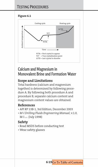
TESTING PROCEDURES
Calcium and Magnesium in Monovalent Brine and Formation WaterScope and LimitationsTotal hardness (calcium and magnesiumtogether) is determined by following proce-dure A. By following both procedure A andprocedure B, separate calcium content andmagnesium content values are obtained.
References• API RP 13B-1, 3rd Edition, December 2003• M-I Drilling Fluids Engineering Manual, v.1.0,
M-I L.L.C. (July 1998)
Safety• Read MSDS before conducting test• Wear safety glasses
6·19
Am
bie
nt
tem
per
atu
re
Time
FCTA = First crystal to appearTCT = True crystallization pointLCTD = Last crystal to dissolve
Cooling cycle Heating cycle
FCTA
TCT
LCTD
Figure 6.1
TESTING PROCEDURES
Equipment and Chemicals Required• EDTA (Standard Versenate) solution 0.01M• Strong buffer solution (ammonium hydroxide/
ammonium chloride)• Calmagite Indicator solution• Titration dish, 100 to 150 mL, preferably white• Three graduated pipettes:
• One 1 mL pipette• One 5 mL pipette• One 10 mL pipette
• 50 mL graduated cylinder• Distilled or deionized water• Glass stirring rod• 8N NaOH or KOH solution• Calcon Indicator or Calver II• Procelain spoon/spatula• Masking Agent: 1:1:2
triethanolamine:tetraethylenepentamine:water (by volume)
Procedure A (total hardness as Ca2+)1. Add approximately 20 mL of distilled water
to titration vessel.2. Add 1 mL of the water or filtrate to be tested.3. Add 1 mL of strong buffer solution.4. Add about 6 drops of Calmagite and mix with
stirring rod. A wine red color will develop ifcalcium and/or magnesium is present.
5. Using a pipette, titrate with StandardVersenate Solution, stirring continuously,until the sample first turns to blue with noundertint of red remaining.
6·20
TESTING PROCEDURES
6. Record the number of mL of StandardVersenate solution used as “A.”
7. Calculate total hardness as Ca2+ (mg/L) =
A x 400mL of sample
CaCO3 (mg/L) = A x 1,000
mL of sample
Procedure B (calcium and magnesium
separately)1. Add approximately 20 mL of distilled water to
the titration vessel.2. Add the same amount of water or filtrate to
be tested as used in procedure A.3. Add 1 mL masking agent.4. Add 1 mL of 8N NaOH or KOH and ∏ porcelain
spoonful (0.2 g) of Calcon Indicator and mixwith stirring rod.
5. Titrate with Standard Versenate solution untilthe indicator turns from wine red to bluewith no undertint of red remaining.
6. Record the number of mL of StandardVersenate required as “B.”
7. Calculate calcium (mg/L) = B x 400mL sample
8. Calculate magnesium (mg/L) = (A – B) x 243mL sample
6·21

TESTING PROCEDURES
Brine DensityScope and LimitationsThis procedure applies to measuring density ofa brine at surface and correcting the density to70° F (21° C).
References• API RP 13J, 3rd Edition, December 2003
Safety• Wear safety glasses
Equipment and Chemicals Required• Hydrometer calibrated at 60° F (16° C)• Hydrometer Cylinder• Thermometer
Note: If you do not know the approximate den-sity of the fluid to be checked, start with a low-range hydrometer and work your way up to thecorrect range. This technique will prevent thebreaking of the heavier hydrometers as they fallthrough the lighter density fluids.
Procedure1. Pour a sample of the fluid to be weighed into
the hydrometer cylinder to within ± 1 in.(25.4 mm) from the top.
2. Gently place the hydrometer into the cylinderand spin it as you release it into the fluid.
3. Allow the hydrometer to stabilize and readthe specific gravity from the spindle. Takeyour reading from the bottom of the meniscus.
4. Record the temperature of the sample using aFahrenheit thermometer.
6·22

TESTING PROCEDURES
Calculation1. Convert the hydrometer reading (specific
gravity) to lb/gal by multiplying the specificgravity x 8.334. This factor relates to the den-sity of water at 60° F (16° C), the temperatureat which the hydrometer is calibrated.
2. Calculate the density correction to 70° F(21° C) using the following equation:
Dc = Dm+ [ CF(Tm – 70) ]
Where:
Dc = Corrected Density
Dm = Measured Density in lb/gal
CF = Hydrometer Correction Factor (see table on page 6·24)
Tm = Temperature of Sample
ExampleHydrometer reading of 1.742 SG at 100° F (38° C)
8.334 x 1.74 = 14.5 lb/gal at 100° F (38° C)
Dc = 14.5 + 0.00363 (100 – 70)
Dc = 14.5 + 0.00363 (30)
Dc = 14.5 + 0.1089
Dc = 14.6 lb/gal at 70° F (21° C)
6·23
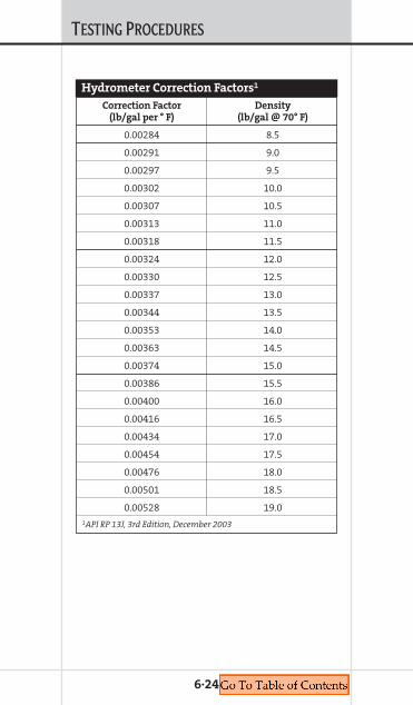
TESTING PROCEDURES
6·24
Hydrometer Correction Factors1
Correction Factor Density (lb/gal per ° F) (lb/gal @ 70° F)
0.00284 8.5
0.00291 9.0
0.00297 9.5
0.00302 10.0
0.00307 10.5
0.00313 11.0
0.00318 11.5
0.00324 12.0
0.00330 12.5
0.00337 13.0
0.00344 13.5
0.00353 14.0
0.00363 14.5
0.00374 15.0
0.00386 15.5
0.00400 16.0
0.00416 16.5
0.00434 17.0
0.00454 17.5
0.00476 18.0
0.00501 18.5
0.00528 19.01API RP 13J, 3rd Edition, December 2003
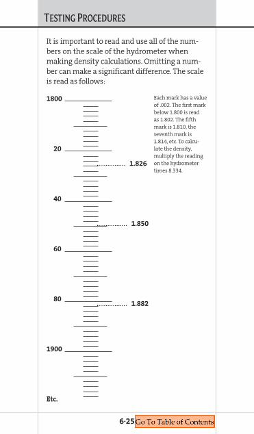
TESTING PROCEDURES
6·25
It is important to read and use all of the num-bers on the scale of the hydrometer whenmaking density calculations. Omitting a num-ber can make a significant difference. The scaleis read as follows:
Each mark has a valueof .002. The first markbelow 1.800 is readas 1.802. The fifthmark is 1.810, theseventh mark is1.814, etc. To calcu-late the density,multiply the readingon the hydrometertimes 8.334.
1800
20
40
60
80
1900
Etc.
1.826
1.850
1.882
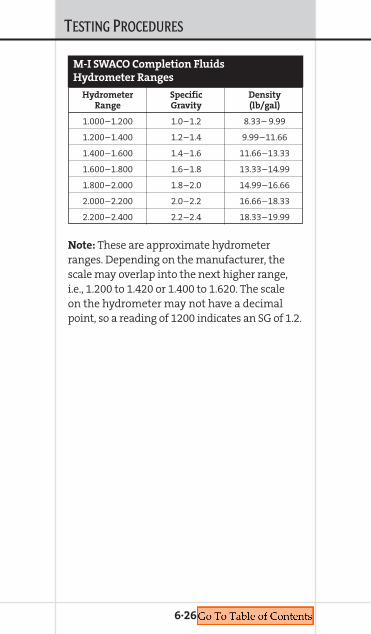
TESTING PROCEDURES
6·26
M-I SWACO Completion Fluids
Hydrometer Ranges
Hydrometer Specific Density Range Gravity (lb/gal)
1.000–1.200 1.0–1.2 8.33– 9.99
1.200–1.400 1.2–1.4 9.99–11.66
1.400–1.600 1.4–1.6 11.66–13.33
1.600–1.800 1.6–1.8 13.33–14.99
1.800–2.000 1.8–2.0 14.99–16.66
2.000–2.200 2.0–2.2 16.66–18.33
2.200–2.400 2.2–2.4 18.33–19.99
Note: These are approximate hydrometerranges. Depending on the manufacturer, thescale may overlap into the next higher range,i.e., 1.200 to 1.420 or 1.400 to 1.620. The scaleon the hydrometer may not have a decimalpoint, so a reading of 1200 indicates an SG of 1.2.

TESTING PROCEDURES
Submitting Samples to Technical Center LaboratoriesScope and LimitationsThis procedure applies to submitting samplesfor testing at the Technical Center in Houston,Texas.
References• Sample Submission Form, current version
found at midhouhq-www01.corp.smith-intl.com (R&E)
• CFR 49, Section 172, accessible at www.pgoaccess.gov\ecfr
• QHSE Manual, current version found at midhouhq-www01.corp.smith-intl.com (QHSE)
Safety• Include MSDS with sample. Label and package
according to DOT.
Procedure for submitting and
packaging a sampleFirst you must obtain a copy of the sample sub-mission from the Web site, or use a copy of theattached form. You can either send in a hardcopy or send it in electronically. This form helpsthe various departments follow the progress ofyour sample.
Then package your sample, include anMSDS, and send it to the following address:M-I SWACO, 5950 North Course Dr., Houston,Texas, 77072. Remember to send it to the atten-tion of the Completion Fluids Laboratory. Pleaseinclude a note with a brief description of thesample, where it’s from, what testing is required,and a contact name and phone number.
6·27

TESTING PROCEDURES
Package and label sample according to com-pany, shipper and DOT requirements. Section 14of the M-I SWACO MSDS includes the DOT clas-sification. The packaging of samples is for themost part common sense. Do not package oilsamples in plastic containers. Oil-base productswill dissolve plastic, this includes bottles andbags. Never label oil samples with grease pens.Package the sample with some thought and itwill arrive in one piece with the labels readable.
Environmental samples require specialhandling, depending on the test that is required.
6·28

TESTING PROCEDURES
Name of submitter:
M-I SWACO entity or Non-M-I SWACO company:
Location:
Phone number and E-mail:
Date submitted:
Report date requested:
Report to:
Lab master number:
Sample identification: (Provide as full andcomprehensive information as is available)
Objective description of problem:
What question(s) do you wish to haveanswered about the sample submitted?(Please be clear and objective)
6·29
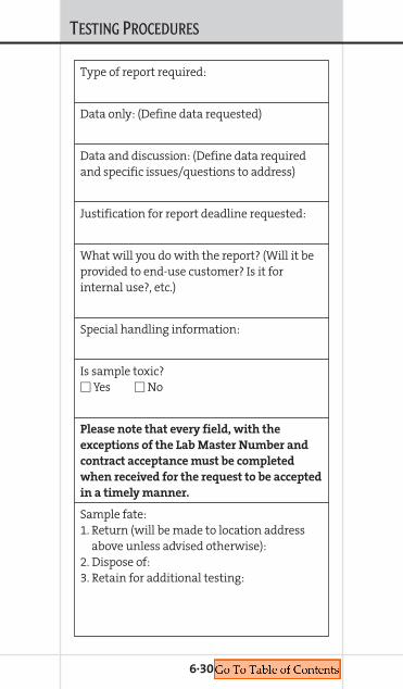
TESTING PROCEDURES
Type of report required:
Data only: (Define data requested)
Data and discussion: (Define data requiredand specific issues/questions to address)
Justification for report deadline requested:
What will you do with the report? (Will it beprovided to end-use customer? Is it forinternal use?, etc.)
Special handling information:
Is sample toxic?� Yes � No
Please note that every field, with the
exceptions of the Lab Master Number and
contract acceptance must be completed
when received for the request to be accepted
in a timely manner.
Sample fate:1. Return (will be made to location address
above unless advised otherwise):2. Dispose of:3. Retain for additional testing:
6·30

RDF TESTING PROCEDURES
COMPLETION FLUIDSMANUAL

RDF TESTING PROCEDURES
Methylene Blue CapacityDescriptionThe methylene blue capacity of drilling fluid isan indication of the amount of reactive clays(bentonite and/or drill solids) present as deter-mined by the Methylene Blue Test (MBT). Themethylene blue capacity provides an estimateof the total Cation Exchange Capacity (CEC)of the drilling-fluid solids. Methylene bluecapacity and cation exchange capacity are notnecessarily equivalent, the former normallybeing somewhat less than the actual cationexchange capacity.
Methylene blue solution is added to a sam-ple of drilling fluid (which has been treatedwith hydrogen peroxide and acidified) untilsaturation is noted by formation of a dye “halo”around a drop of solids suspension placed onfilter paper. Variations of the procedure usedon the drilling fluid can be performed on drillsolids and commercial bentonite to allow anestimate of the amount of each type of solidpresent in the fluid.
Drilling fluids frequently contain substancesin addition to reactive clays that adsorb methyl-ene blue. Pretreatment with hydrogen peroxide(see Procedure, Item b) is intended to removethe effect of organic materials such as lignosul-fonates, lignites, cellulosic polymers, polyacry-lates, and the like.
EquipmentThe following equipment is needed to performthe methylene blue test:
6·32

RDF TESTING PROCEDURES
a. Methylene blue solution: 3.2 grams reagentgrade methylene blue (C16H18N3SCl)/L (1 cm3 = 0.01 milliequivalent) (CAS #61-73-4).
Note: The moisture content of reagent grademethylene blue must be determined each timethe solution is prepared. Dry a 1.000-gram por-tion of methylene blue to a constant weight at200° ±5° F (93° ±3° C). Make the appropriate cor-rection in the weight of methylene blue to betaken to prepare the solution as follows:
g =
b. Hydrogen peroxide: 3% solution (CAS #7722-88-5)
c. Dilute sulfuric acid: approximately 5 newtonsd. Syringe (TD): 2.5 cm3 or 3 cm3
e. Erlenmeyer flask: 250 cm3
f. Burette (TD): 10 cm3, micropipette: 0.5 cm3, orgraduated micropipette: 1 cm3
g. Graduated cylinder (TD): 50 cm3
h. Stirring rodi. Hot platej. Whatman No. 1 filter paper, or equivalent
ProcedureFollow this procedure to perform the MBT:a. Add 2 cm3 of drilling fluid (or suitable volume
of drilling fluid to require from 2 to 10 cm3 ofmethylene blue solution) to 10 cm3 of waterin the Erlenmeyer flask. To assure thatexactly 2 cm3 are being added, use thefollowing procedure:
3.2weight of dried sample
Weight of sample to be taken
6·33

RDF TESTING PROCEDURES
1. The syringe should have a capacity of morethan 2 cm3 — generally 2 or 3 cm3. Byusing a larger syringe, it is not necessaryto remove the air trapped in the syringe.
2. The air or gas entrained in the drillingfluid must be removed. Stir the drillingfluid to break the gel and quickly draw thedrilling fluid into the syringe. Then, slowlydischarge the syringe back into the drillingfluid, keeping the tip submerged.
3. Again, draw the drilling fluid into thesyringe until the end of the plunger isat the last graduation on the syringe(for example, at the 3-cm3 line on a3-cm3 syringe).
4. Deliver 2 cm3 of drilling fluid by pushingthe plunger until the end of the plunger isexactly 2 cm3 from the last graduation onthe syringe. Thus, in a 3-cm3 syringe, itwould be at the 1-cm3 line.
b. Add 15 cm3 of 3% hydrogen peroxide and0.5 cm3 of sulfuric acid. Boil gently for10 min, but do not allow to boil to dryness.Dilute to about 50 cm3 with water.
c. Add methylene blue to the flask in incre-ments of 0.5 cm3. If the approximate amountof methylene blue solution necessary toreach the endpoint is known from previoustesting, larger increments (1 to 2 cm3) can beused at the beginning of the titration. Aftereach addition of methylene blue solution,swirl the contents of the flask for about 30sec. While the solids are still suspended,remove one drop of liquid with the stirringrod and place the drop on the filter paper.The initial endpoint of the titration is
6·34

RDF TESTING PROCEDURES
reached when dye appears as a blue orturquoise ring surrounding the dyed solids.
d. When the blue tint spreading from the spotis detected, shake the flask an additional2 min and place another drop on the filterpaper. If the blue ring is again evident, thefinal endpoint has been reached. If the bluering does not appear, continue as before (seeItem C) until a drop taken after 2 min showsthe blue tint.
CalculationReport the Methylene Blue Capacity (MBT) ofthe drilling fluid, calculated as follows:
=
Alternately, the MBT can be reported aspounds per barrel bentonite equivalent (basedon bentonite with a cation exchange capacity of70 meq/100 grams) calculated as follows:
1.=
2.=
Note: The pounds per barrel bentonite equiva-lent (from Equations 1 or 2) is not equal to theamount of commercial bentonite in the drillingfluid. Reactive clays in the drill solids contributeto this quantity as well as commercial bentonite.
2.85 (bentonite equivalent, lb/bbl)
Bentonite equivalent, kg/m3g,
5 (methylene blue, cm3)Drilling fluid, cm3
Bentonite equivalent, lb/bbl
Methylene blue, cm3
Drilling fluid, cm3
Methylene bluecapacity, cm3/cm3
6·35

RDF TESTING PROCEDURES
6·36
M-I SWACO Recommended Procedures for Measuring Low-Shear-Rate Viscosity (LSRV) for FLOPRO FluidsThe following standardized procedures are rec-ommended when measuring LSRV of a FLOPRO*fluid. These procedures are designed to negateartifacts produced from variances in test proce-dure. Every effort should be made to use theseprocedures in order to make valid comparisonsbetween wells.
EquipmentTesting will be made using the Brookfield^LVDV-II+ or LVDV-III digital viscometer withguard leg and cylindrical spindles (#1-4). TheLVDV-II+ is the most widely used viscometer.The LVDV-III model has a wider speed selectionand also has a programmable feature neitherof which is necessary for FLOPRO applications.The spindle viscosity ranges at .3 RPM usingthe LVDV-II+ or LVDV-III are: #1 to 20,000 cP,#2 to 100,000 cP, #3 to 400,000 cP and #4 to2,000,000 cP.
When ordering a Brookfield viscometer spec-ify LVDV-II+ or LVDV-III with cylindrical spin-dles. The LV prefix designates the proper springtorque for the viscosity ranges M-I SWACOdesires. A set of four appropriately sized cylin-drical spindles will be sent. Also input voltageand frequency should be indicated when order-ing. The units are available in 115, 220 or 230volts AC and 50 or 60 Hertz frequency.
Other necessary equipment includes thelarge OFI thermo cup (3∏-in. [82.6-mm] dia by^Mark of Brookfield Engineering Laboratories, Inc.

RDF TESTING PROCEDURES
4-in. [101.6-mm] deep) and a mixing device tohelp heat the fluid sample evenly.
LocationLocate the Brookfield where a stable power sup-ply is available. It should also be located wherevibrations from the rig are minimal. Rig vibra-tions may contribute to inaccurately low LSRVmeasurements. Dust may damage the electron-ics or the bearings so a dust-free atmosphereshould be located.
SetupRemove the viscometer from the case. Installgear assembly on stand with rack and insertBrookfield viscometer post in assembly andtighten clamp screw. Level viscometer by rotat-ing it slightly on the stand and/or by adjustingfeet. Use the bubble level on the top as a guide.
Plug temperature probe into receptacle onthe back of the viscometer. Make sure powerswitch on the rear of the viscometer is OFF. Plugpower cord into receptacle on the back of theviscometer and plug into appropriate AC socket.The AC input voltage and frequency must be
within the appropriate range as shown on the
name plate of the viscometer.
Note: The DV-II+ must be earth grounded to
ensure against electronic failure!
This is a delicate electronic instrument. Careshould be taken to avoid power surges and fre-quency variations. Disconnect the viscometerwhen not in use.
Pour the FLOPRO fluid to be tested to within ahalf inch of the top of the Thermo cup and heatto desired temperature. The fluid sample shouldbe tested at the same temperature as the other
6·37

RDF TESTING PROCEDURES
rheological properties. The sample should bestirred while heating to equalize the tempera-ture throughout the sample. A Hamilton Beachtype mixer may be used. Stir at a slow rate toavoid overshearing the fluid which may resultin polymer degradation. Avoid entrapping airwhile stirring. Entrapped air will result in erro-neous readings.
InitializingWhile heating the sample, remove the rubberband holding the viscometer shaft in place. Theviscometer uses a gem bearing and calibratedspring. Avoid impact and twisting of the shaft.Always replace the rubber band when not usingthe viscometer.
Turn on the viscometer. The digital screenwill display the operations as the viscometerautozeroes itself. The following screen descrip-tions are for the LVDV-II+ viscometer, the mostwidely used model.
When the power is on the screen will flash“Brookfield DV-II+ LV Viscometer,” then “Version3.0.” The screen then automatically changes to“Remove spindle. Press any key.” Press any ofthe yellow keys and the display changes to“Autozeroing Viscometer.” After autozeroing thescreen will display “Replace spindle. Press anykey.” Select the appropriate cylindrical spindlefor the desired viscosity. Most applications willuse the number 2 spindle. Note the spindles aremarked on the neck.
Attach the spindle by threading it onto theshaft. Note these are left-handed threads. Holdthe shaft in one hand to prevent damage to thespring and bearing while tightening the spin-dle. After tightening the spindle, press one of
6·38

RDF TESTING PROCEDURES
the yellow buttons on the key pad. The defaultdisplay will appear on the screen.
Viscometer DisplayThe screen will look something like this:
Values may vary according to what was lastused.
The upper left corner displays viscometerreadings these may be in the following units:
% Viscometer Torque (%)cP Viscosity (cP or mPa)SS Shear Stress (always 0 due to spindle
configuration)SR Shear Rate (always 0 due to spindle con-
figuration)The default units for the LVDV-II+ is %. The
value in the upper left corner should be <+1.0 %when not in use. A value greater may indicatedamage to the bearing or spring.
M-I SWACO is using viscosity in cP (centipoise)as the standard reading. To select the appropri-ate units, press Select Display key until the cPvalue appears. The SI unit mPa·s is equivalent tocP (40,000 cP = 40,000 mPa·s).
The upper right hand value is the spindlecode. The code allows the viscometer to cor-rectly calculate viscosity for a given spindlegeometry. The code for the #2 spindle is S62
and for the #3 spindle it is S63. If the correctcode is not on the screen, press Select Spindle
key. The S will blink. Use the orange up anddown arrow keys to search for the correct spin-dle code. When the correct code is found, press
% 0.0 S62
0.0 RPM 70.5° F
6·39
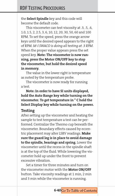
RDF TESTING PROCEDURES
the Select Spindle key and this code willbecome the default code.
This viscometer can test viscosity at .3, .5, .6,1.0, 1.5, 2, 2.5, 3, 6, 10, 12, 20, 30, 50, 60 and 100RPM. To set the speed, press the orange arrowkeys until the desired speed appears to the rightof RPM. M-I SWACO is doing all testing at .3 RPM.When the proper value appears press the setspeed key. Note: The viscometer is now run-
ning, press the Motor ON/OFF key to stop
the viscometer, but hold the desired speed
in memory.
The value in the lower right is temperatureas noted by the temperature probe.
The viscometer is now ready for runninga test.
Note: In order to have SI units displayed,
hold the Auto Range key while turning on the
viscometer. To get temperature in ° C hold the
Select Display key while turning on the power.
TestingAfter setting up the viscometer and heating thesample to test temperature a test can be per-formed. Centralize the Thermo cup beneath theviscometer. Boundary effects caused by eccen-tric placement may alter LSRV readings. Make
sure the guard leg is in place to avoid damage
to the spindle, bearings and spring. Lower theviscometer until the recess in the spindle shaftis at the top of the fluid. While lowering the vis-cometer hold up under the front to preventexcessive vibration.
Set a timer for three minutes and turn onthe viscometer motor with the Motor ON/OFF
button. Take viscosity readings at 1 min, 2 minand 3 min while the viscometer is running.
6·40

RDF TESTING PROCEDURES
These values should be labeled LSRV1, LSRV2and LSRV3, respectively. Part of the first minutewill involve torquing the spring. Generally thefluid will reach its maximum viscosity withinthe 3-min time. The 3-min reading may actuallybe less than the 2-min reading. If the 3-minreading is less than the 2-min reading thespindle is probably slipping as it “drills a hole”in the fluid.
After the test, turn off the viscometer andraise the spindle above the fluid.
CleanupTurn off the viscometer. Remove the spindle,then the guard leg. Wash them thoroughly.Replace the guard leg and reinstall the rubberband on the shaft. Keep the viscometer awayfrom water and dust and unplug it when not inuse to avoid power surges.
CalibrationCalibration fluids are available from Brookfieldand their agents. The viscometer should be cali-brated regularly. The procedures are outlined inthe “Brookfield Digital Viscometer OperatingInstructions Manual,” which is included withthe viscometer. This manual also contains moredetailed information not discussed here.
SummaryThe M-I SWACO standard LSRV test for FLOPRO
fluids is outlined in the following steps.1. Use Brookfield LVDV-II+ viscometer at .3 RPM.2. Use spindle 2 for LSRV <100,000 cP, spindle 3
for LSRV >100,000 cP.3. Test sample at same temperature as other
flow properties.
6·41
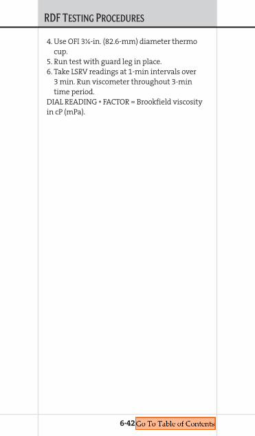
RDF TESTING PROCEDURES
6·42
4. Use OFI 3∏-in. (82.6-mm) diameter thermocup.
5. Run test with guard leg in place.6. Take LSRV readings at 1-min intervals over
3 min. Run viscometer throughout 3-mintime period.
DIAL READING * FACTOR = Brookfield viscosityin cP (mPa).

RDF TESTING PROCEDURES
Field Test Procedure for Drill Solids Determination Required equipment and material• Top loading balance• Hot plate with magnetic stirrer• API filter press and accessories• 250-mL beaker
Required chemicals• 15% Hydrochloric Acid (HCl) — use with
caution• Defoamer1. Weigh equivalent of 35 mL of mud into
250-mL beaker.2. Add several drops of defoamer.3. Add stirring bar to beaker and place on stirrer
at slow speed.4. Slowly add 50 mL of 15% HCl, don’t let sample
foam over. This might take a few minutes.5. After all HCl has been added, place on hot
plate and bring to boil (this will break downthe polymer so the sample will filter). (Forfluids using NaCl as the bridging material,add 50 mL of water to dissolve the bridgingmaterial.)
6. Weigh API Whatman 50 filter paper.7. Cool sample and add to API filter cell.
Filter sample.8. Take out filter paper with solids and put
in oven until dry.9. Weigh and record weight of filter paper
with solids.
6·43

RDF TESTING PROCEDURES
10. Subtract original weight of filter paper (step#6) from final weight of filter paper withsolids (step #9). This is reported as drillsolids.
CalculationsFor 35 mL of mud (1/10 bbl equivalent):• Weight of solid residue x 10 = lb/bbl of
drill solids (Note: 9.1 lb/bbl of drill solids =1% by volume of drill solids)
6·44

Chapter 7DISPLACEMENT TECHNOLOGY
COMPLETION FLUIDSMANUAL
7.D
ISPLACEMENTTECHNOLOGY
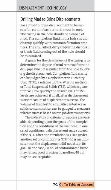
DISPLACEMENT TECHNOLOGY
Drilling Mud to Brine DisplacementsFor a mud-to-brine displacement to be suc-cessful, certain basic criteria must be met.The casing in the hole should be cleaned ofmud. The completion fluid in the hole shouldcleanup quickly with common filtration prac-tices. The emulsified, dirty (requiring disposal)or trash fluid coming out of the hole shouldbe minimized.
A guide for the cleanliness of the casing is todetermine the degree of mud removal from thedrill pipe when it is pulled from the hole follow-ing the displacement. Completion fluid claritycan be judged by a Nephelometric TurbidityUnit (NTU), a relative light-scattering method,or Total Suspended Solids (TSS), which is quan-titative. How quickly the desired NTU or TSSlevels are achieved, if at all, after displacementis one measure of displacement success. Thevolume of fluid lost to emulsified interface orsolids contamination can be gauged to measurerelative success based on pre-job determinations.
The indicators of criteria for success are vari-able, depending upon the goals of the comple-tion and the conditions of the wellbore. In oneset of conditions, a displacement may succeedif the NTU after one circulation is <100; underanother set of conditions, a NTU >40 is an indi-cator that the displacement did not attain itsgoal. In one case, 80 bbl of contaminated brinemay reflect good practice; in another, 40 bblmay be unacceptable.
7·1
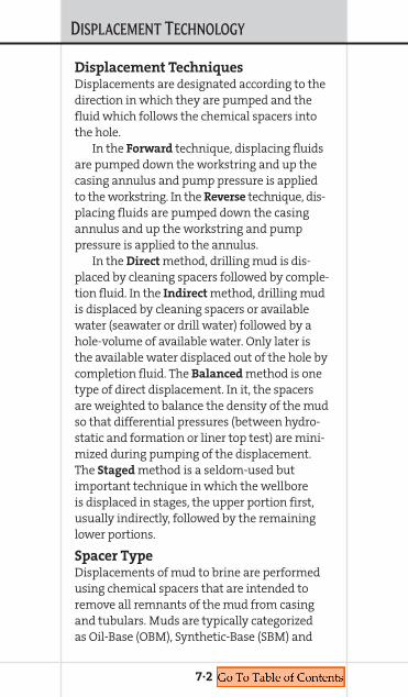
DISPLACEMENT TECHNOLOGY
Displacement TechniquesDisplacements are designated according to thedirection in which they are pumped and thefluid which follows the chemical spacers intothe hole.
In the Forward technique, displacing fluidsare pumped down the workstring and up thecasing annulus and pump pressure is appliedto the workstring. In the Reverse technique, dis-placing fluids are pumped down the casingannulus and up the workstring and pumppressure is applied to the annulus.
In the Direct method, drilling mud is dis-placed by cleaning spacers followed by comple-tion fluid. In the Indirect method, drilling mudis displaced by cleaning spacers or availablewater (seawater or drill water) followed by ahole-volume of available water. Only later isthe available water displaced out of the hole bycompletion fluid. The Balanced method is onetype of direct displacement. In it, the spacersare weighted to balance the density of the mudso that differential pressures (between hydro-static and formation or liner top test) are mini-mized during pumping of the displacement.The Staged method is a seldom-used butimportant technique in which the wellboreis displaced in stages, the upper portion first,usually indirectly, followed by the remaininglower portions.
Spacer TypeDisplacements of mud to brine are performedusing chemical spacers that are intended toremove all remnants of the mud from casingand tubulars. Muds are typically categorizedas Oil-Base (OBM), Synthetic-Base (SBM) and
7·2

DISPLACEMENT TECHNOLOGY
Water-Base (WBM). Spacers used to breakdownand remove these three mud systems differ intheir chemical composition.
Water is the best solvent for WBM. A high-pH solution of caustic soda in drill water orseawater is very effective at destroying theintegrity of WBM. A surfactant (SAFE-SURF* W
or WN) in drill water or seawater can be used tofurther clean the pipe and water-wet the pipesurface. A viscous pill is often used to sweepmud solids and debris out of the hole. Somecombination of similarly designed spacers willsuffice to clean the hole of water-base mud,always in conjunction with best displacementpractices.
OBM and SBM are more complex systemsand more difficult to remove from pipe sur-faces. Oil is the best solvent for removing eitherof these systems, but at some point a chemicaltransition must be made to water-wet the pipesurface. M-I SWACO recommends initiating thisaqueous transition immediately following thebase oil pre-flush. This spacer, called the tran-sition spacer, must be based on chemistry thatis compatible with the mud, the base oil andthe cleaning or wash spacer that follows.Compatibility tests performed prior to the dis-placement determine the composition of thistransition spacer and confirm that massive orcomplex emulsions will not form at the inter-faces of the displaced and displacing fluids.
Cleaning or wash spacers follow the transi-tion spacers in sequence. They are also moredifficult to determine for OBM and SBM thanfor WBM. Surfactants (SAFE-SURF O, E or NS)and solvents (SAFE-SOLV* OM, E or 148) are less
7·3
DISPLACEMENT TECHNOLOGY
effective at cooler temperatures, such as mightbe seen at a deepwater mudline or even in a shal-low well. Higher concentrations of surfactantand solvent are required for removing higherweight OBM and SBM than for removing lowerweight muds. Also combinations of surfactantand solvent will exhibit differing effects whencleaning OBM or SBM. Synthetic muds are gener-ally more tenacious about gripping the pipe sur-face. Laboratory tests should be run to determinethe effectiveness of these spacers prior to per-forming a displacement of OBM or SBM.
M-I SWACO OBM and SBM displacement rec-ommendations typically consist of a weighted,viscous transition spacer, one or two cleaningspacers (of solvent/surfactant combined orindividually) and a viscous separation spacer.Regardless of mud type, following the separa-tion spacer one drum of flocculant (FILTER FLOC*)in 100 bbl seawater or brine is often used tohelp carry solids to the surface. If the flocculantis added to brine in a direct displacement, thebrine can be directed to the return pit with therest of the active brine system.
Spacer SizeThe lead or transition spacer in an OBM or SBMdisplacement should be sized to eliminate theintermixing of the fluids ahead of and behind it.(This is less of a critical issue in WBM displace-ments, but the same design techniques apply.)Conventional practice defines this interval as500 to 1,500 ft (150 to 450 m) of coverage inthe largest annular area, depending upon theunique experience of the design engineer.However, if two wells are compared, both with95⁄8-in. (244-mm) casing and 4-in. (102-mm) drill
7·4
DISPLACEMENT TECHNOLOGY
pipe, one 8,000 ft (2,440 m) deep and the other20,000 ft (6,100 m) deep, conventional practicesuggests these two wellbores require identicallysized transition spacers. M-I SWACO recom-mends the transition spacer be sized based onthe well capacity, typically 10% of the totalannular volume. This accounts for annular sizeas well as well depth. In this case, the 8,000-ft(2,438.4-m) well will have a 25 to 50 bbl (4 to8 m3) transition spacer while the 20,000-ft(6,096-m) well will have a 75 to 100 bbl (12 to16 m3) transition spacer. For logistical conven-ience, the spacer size is rounded up or down tofit portable storage tanks, if necessary.
The size of the cleaning spacer should bedetermined by the total surface area to becleaned, contact time and flow rate required forcleaning and concentration of wash chemical.It has been estimated that the average mud filmon the casing and tubing wall is between 1⁄64-and 1⁄32-in. (0.4- and 0.8-mm) thick. The volumeof this mud film can be calculated based on thesize and length of the drill pipe and casing.Since cleaning spacers will become contami-nated with mud over the course of the displace-ment, a well-designed cleaning spacer will havea concentration great enough to provide effec-tive chemical activity in the latter stages ofthe displacement. A basic design begins withenough spacer volume and wash chemical con-centration to account for mud contaminationup to 25%.
Based on this criteria, M-I SWACO recom-mends cleaning spacers sized at a minimumof 4 times the estimated volume of mud filmon the total area of tubing and casing, or,
7·5

DISPLACEMENT TECHNOLOGY
enough concentration to effectively clean whencontaminated with mud at 25% volume. If thatvolume/concentration is sufficient to achievethe necessary contact time for effective clean-ing at the displacement pump rate, no size/con-centration adjustment is required. However, ifpre-job spacer testing indicates more contacttime or concentration is needed, spacer size/concentration should be adjusted accordingly.
Factors that may cause a further increase ofcleaning spacer size are: dead space in blendingpits and lines, inability to rotate and/or recipro-cate, inability to get the cleaning spacer in tur-bulent flow in part of the wellbore or poor mudconditioning (especially stagnant mud in high-temperature conditions).
Pump Rate and Flow RegimePump rate for a mud-to-brine displacementshould be maintained between two limits.The minimum limit is that rate required toachieve turbulent flow in the cleaning spacer.The maximum limit is that pump rate whichlowers the contact time of the cleaning spacerbelow the acceptable level as determined byprior lab testing.
It is generally recognized that the cleaningspacer will be most effective when it is in tur-bulent flow. Turbulence is usually attributedto a surfactant-based Newtonian fluid with aReynolds’ Number (NRe) >4,000 (2,200 <4,000being transitional flow). Experience in displace-ment implementation suggests using a higherlower-limit in design criteria, often on the orderof NRe ~ 6,000 to 8,000 if possible. Factorswhich determine the NRe of a fluid are its den-sity, Apparent Viscosity (AV), velocity and area
7·6

DISPLACEMENT TECHNOLOGY
of flow. NRe is inversely proportional to thefluid viscosity. Since cleaning spacers are non-viscous, a high NRe can usually be achievedwith relative ease.
Spacer ChemicalsSpacers are designed using surfactants, sol-vents, viscosifiers and flocculants. M-I SWACOhas developed a line of displacement spacerproducts that are designed to promote wellborecleaning while minimizing rig time and mate-rial waste. This product line is called the SAFE*Series.
Surfactants — SAFE-SURF W, WN and
NS are surfactant blends intended for use inremoving water-base mud residues. All aredesigned for use in freshwater or seawaterand contain strong water-wetting surfactants.The pH of these blends varies from very high(W) to near neutral (WN).
SAFE-SURF O, E and NS are formulated forremoval of OBM and SBM. These surfactantscan be blended in freshwater or seawater andare effective when blended in salt brine. pHranges from very low (O) to moderately high (E).The products are formulated to satisfy differingregulatory requirements in various parts of theworld. Surfactants are used at 3 to 20% byvolume in spacer solutions.
Solvents — SAFE-SOLV E, OM and 148 aresolvent/surfactant blends intended for use inOBM and SBM displacements. They contain noaromatic hydrocarbons or toxic alkyl phenols.These solvents are used in displacement spacersat percentages between 3 and 35% and arepumped neat when used to pickle pipe forpipe-dope removal. SAFE-T-PICKLE* is a special
7·7

DISPLACEMENT TECHNOLOGY
7·8
solvent developed for removal of pipe dope.SAFE-T-PICKLE is run as a neat solvent.
Viscosifiers — M-I SWACO prefers the use ofshear-thinning polymers when possible in muddisplacements. DUO-VIS*, DUO-VIS L, FLO-VIS*Land FLO-VIS PLUS are xanthan polymer systemsthat are used to build viscous spacers. DUO-VIS
is unclarified xanthan, FLO-VIS L is liquid clari-fied xanthan and FLO-VIS PLUS is coated, clari-fied powder. The proper product is selectedbased on well conditions and completion goals.
SAFE-VIS*, SAFE-VIS OGS, SAFE-VIS LE,
SAFE-VIS E and SAFE-VIS HDE are HEC polymersystems also used to viscosify displacementspacers. SAFE-VIS is dry powder, OGS is pre-slurried in a synthetic carrier that passes oiland grease and static sheen tests required inthe Gulf of Mexico and HDE is pre-slurried ina synthetic carrier to enable viscosification ofhigh-density brine. SAFE-VIS is typically recom-mended at 3.5 lb/bbl (10 kg/m3). SAFE-VIS OGS,
LE and E are used between 0.75 to 1.5 gal/bbl(19 to 38 kg/m3). SAFE-VIS HDE is recommendedbetween 3 and 5 gal/bbl (63 and 105 kg/m3).
Flocculants — SAFE-FLOC* I and FILTER FLOC
are used to flocculate dispersed solids and tohelp bring solids to the surface. SAFE-FLOC I isoften used in brine reclamations or added onlocation when dissolved iron creates a clarityproblem in the completion brine. It can be addedat 0.25 to 1% by volume to the working brinesystem to help coagulate and then flocculatecolloidal iron. FILTER FLOC is most often includedin the first 100 bbl (16 m3) of seawater or brinethat follows the displacement spacer sequence

DISPLACEMENT TECHNOLOGY
into the hole. This helps bring suspended solidsto the surface where they can be filtered out ofthe working system.
Mechanical AidsMechanical aids consist of those elementswhich are neither chemical nor hydraulic,such as mud conditioning, pipe rotation andreciprocation and cleaning tools.
Mud conditioning may be the most under-stated stage of the displacement process. Mudproperties, i.e., PV and YP, should be reduced tominimum values prior to displacement. In mostdisplacement applications, a few additionalhours spent properly conditioning the mudcan save an extra day of hole cleaning.
Guidelines are available for rate of rotationduring circulation and displacement. Pipe rota-tion is critical for hole cleaning in hole angles>30°. Reciprocation also helps disturb mudadhering to the pipe wall. It is generally recom-mended that pipe reciprocation be performedduring mud circulation and during the displace-ment only after the spacers have entered thecasing annulus. To keep fluid flowing on-bottomduring displacement, reciprocation should belimited to one joint of pipe, rather than onestand, during that time.
Casing cleaning tools are an integral com-ponent of mud displacement. The M-I SWACOSPEEDWELL division provides casing brushes andscrapers, jetting tools, magnets and boot bas-kets that are put in-string during the casingclean-out. Refer to the SPEEDWELL tools sectionin this manual.
7·9
Chapter 8VISCOSIFIERS AND FLUID-LOSS CONTROL
COMPLETION FLUIDSMANUAL
8. VISCOSIFIERS
ANDFLUID-LOSSCONTROL
VISCOSIFIERS AND FLUID-LOSS CONTROL
Loss of completion fluids to permeable forma-tions will usually impair the production ofhydrocarbons. Increasing water saturation, scal-ing and emulsion formation are examples offormation damage that can occur. Furthermore,if the rate of losses during the completionprocess is too great, continuing with operationssuch as tripping in and out of the hole may notbe possible. As a result, controlling fluid losses isan important consideration when designingand carrying out the completion. Whereas bothmechanical and chemical means of controllinglosses are available, in many cases, mechanicalmeans are either impractical or simply not suit-able. Therefore, fluid losses are very often con-trolled by chemical means, i.e., spotting ‘pills’of one sort or another. An important featureof these pills is that they control losses withthe least possible damage to the productivityof the well.
Reducing the density of the completion fluidto lessen the differential pressure between thewellbore and the formation is an effectivemeans of reducing the rate of losses. However,adjusting the brine density requires an accurateknowledge of both the Bottomhole Pressure(BHP) and the hydrostatic pressure exerted bythe brine. The density of the completion fluidis selected to provide a certain overbalancepressure in the wellbore, often 200 to 300 psi(13.8 to 20.7 bar). In deep, hot wellbores, littlemargin of error is available. Consequently, den-sity reduction is often not allowed unless reli-able data is provided that can assure that adensity-cut is an acceptable option.
8·1
VISCOSIFIERS AND FLUID-LOSS CONTROL
Pills commonly used to control downholelosses include, solids-free viscous pills, cross-linked polymer pills and those containing solu-ble, sized bridging particles such as calciumcarbonate or sodium chloride. Unlike the cross-linked and filter-cake building systems, solids-free viscous pills do not stop losses, but rather,reduce the rate of loss. The effectiveness of a vis-cous pill depends on the length and permeabil-ity of the thief zone, the differential pressure,the viscosity of the pill under downhole condi-tions and just as important, the quality of itspreparation. To be truly solids-free and to be asnon-damaging as possible, viscous pills shouldbe sheared and filtered (minimum 10 micronabsolute) to eliminate “fish eyes” that will act asplugging solids and make breakers and clean-up techniques much less effective.
Typically, these viscous pills are preparedwith a polymer that is soluble in the completionfluid, provides viscoelastic behavior, maintainsviscosity under downhole conditions and canbe “broken” with available breakers such asacids, enzymes and oxidizers. The most com-mon examples include Hydroxyethylcellulose(HEC), and Xanthan Gum (XC). In all cases, thehigh-purity, clarified versions of these polymersshould be used. Lower grade versions of HECand XC, or non-clarified systems such as manyof the guar gums and carboxy-celluloses, aregenerally not recommended. M-I SWACO offershigh-purity polymer systems within theSAFE-VIS (HEC) and FLO-VIS (XC) product lines.Synthetic polymers that are neither acid solubleor acid compatible are not recommended unlessextreme conditions warrant such use.
8·2

VISCOSIFIERS AND FLUID-LOSS CONTROL
Cross-linked pills offered by M-I SWACO(SAFE-LINK*) are based on a derivatized HEC inwhich anionic functional groups are graftedonto the polymer backbone and cross-linkedwith Magnesium Oxide. The cross-linkingcauses the polymer to form a 3-dimensionalnetwork which produces a gel structure withthe consistency a thick gelatin. Similar cross-linked systems are available in the industry,some of which are mixed on the rig, requiringspecial blending units and a trained technicianto properly prepare. The SAFE-LINK systems arepre cross-linked in base brine and supplied tothe rig in 5-gal (18.9 L) buckets. No specialblenders or training is required to mix thesepills. The SAFE-LINK gel is simply added to a vis-cous HEC pill or to the base brine, stirred (notsheared) and pumped. SAFE-LINK pills are sup-plied with densities from 11 to 16 lb/gal (1.32to 1.92 SG).
When the solids-free, linear gel or cross-linked pills are ineffective, pills that form anexternal filter cake are required. Only solublebridging agents such as calcium carbonate orsodium chloride should be used in these appli-cations. The particle size distribution of thesolids in these pills is selected to bridge eitheron the surface of the formation (OPTIBRIDGE*pills) or on the inside surface of the productionscreen (SEAL-N-PEEL* pills). These systemsrequire knowledge of the screen type and/orformation pore size. In addition to the basebrine and the sized particles, such solids-containing pills use shear thinning polymerswith good low-shear-rate viscosity to carry andsuspend the solids and a soluble binding agent
8·3

VISCOSIFIERS AND FLUID-LOSS CONTROL
to form a low-permeable matrix in combina-tion with the solids. Xanthan gum and starchare the most common examples of these addi-tives. Because these pills form a filter cake ofextremely low permeability, and in some cases,form an impermeable “plug” in a perforationtunnel, they can be more difficult to clean upthan their solids-free counterparts and usuallyrequire a post-placement cleanup treatment.On the other hand, SEAL-N-PEEL pills seal onthe production screen surface with very littlematrix invasion and contain surface tensionreducing agents that allow the filter cake to“peel” from the surface with minimal draw-down pressure.
HECHydroxyethylcellulose (HEC) is a nonionic, ethylether derivative of cellulose. It is the most com-mon polymer used to viscosify clear brine com-pletion fluids. It is the only polymer soluble inall standard, non-formate completion fluids,regardless of density. Dry HEC polymer must beadded slowly when used to viscosity brine; oth-erwise the brine immediately wets the surfaceof the polymer before it has a chance to disperse.This leaves a dry inner core surrounded by ahydrated outer layer (fish eyes) that is nearlyimpossible to hydrate further and must be fil-tered. Shearing and filtering is recommendedwhen preparing HEC pills, especially if the pillis to be used for fluid-loss control.
Adding dry HEC to concentrated brine willusually require heat to fully hydrate and todevelop complete viscosity profile. The amountof heat required to easily hydrate HEC in high
8·4
VISCOSIFIERS AND FLUID-LOSS CONTROL
density brine is a function of the total salt insolution, the amount of HEC added, the shearrate of the mix and the total time. A generalrule of thumb for fluid systems above about12 lb/gal (1.44 SG) is 120° to 140° F (48.8° to60° C), mixed for 6 to 10 hrs under high shear.Operationally, this means circulating the fluidthrough a centrifugal pump until the temper-ature is reached, slowly adding the polymerand continuing to circulate for 6 to 10 hrs oruntil the viscosity no longer increases withadditional mixing. In order to minimize theformation of “fish eyes,” it is important to addpolymer slowly and ensure that all lumps of dryHEC are completely desegregated before adding.
HEC is completely acid soluble. The pre-mium grades produce less than 0.1 wt % residueafter exposure to HCl. HEC pills can be “broken”with HCl and organic acids and mild oxidizers.
HEC can be stabilized at temperaturesgreater than 250° F (121.1° C), depending on thebase brine. Contact your M-I SWACO representa-tive for recommendations.
SAFE-VISSAFE-VIS is a high-grade, clarified HEC polymer.It is a glyoxylated form of HEC with an averagemolecular weight of approximately 1,000,000daltons. This glyoxyl coating retards hydrationuntil either time, temperature or solution pH(above about 7) strips the coating from the sur-face. This retardation allows a more controlledand full hydration. SAFE-VIS is used to viscosifyfreshwater, seawater or brine fluids used inworkover and completion operations. SAFE-VIS
is normally added at concentrations of 2 to
8·5
VISCOSIFIERS AND FLUID-LOSS CONTROL
4 lb/bbl (0.9 to 1.8 kg/bbl) for viscous pillsand 0.1 to 0.5 lb/bbl (0.05 to 0.23 kg/bbl) fordrag reduction.
SAFE-VIS is packaged in 50-lb (22.7-kg)multi-wall, waterproof sacks.
SAFE-VIS HDE SAFE-VIS HDE liquid viscosifier is a suspensionof high-quality HEC polymer in water-solublecarrier. It is specially formulated for high den-sity CaCl2, CaCl2/CaBr2, CaBr2, CaBr2, CaCl2/CaBr2/ZnBr2 and most other divalent brines.Treatments usually range between 2 to 5 gal/bbl(7.6 to 18.9 L/bbl) of completion fluid. Specialmixing procedures are required for ZnBr2
fluids in the 15 to 16.5 lb/gal (1.8 to 1.98 SG)density range.
SAFE-VIS HDE is packaged in 5-gal (18.9-L)plastic cans. SAFE-VIS HDE contains 4.5 lb(2.04 kg) HEC per 5-gal (18.9-L) can.
SAFE-VIS OGSSAFE-VIS OGS liquid viscosifier is a suspensionof high-quality HEC polymer in a water dis-persible, synthetic carrier. SAFE-VIS OGS liquidviscosifier is specially formulated to pass Oiland Grease, LC50 and Static Sheen Test require-ments for offshore GoM use. The product vis-cosifies single salt CaCl2 and CaBr2 brinesand all monovalent-salt brines. Treatmentsusually range between 0.5 to 1.5 gal/bbl (1.9to 5.7 L/bbl) of completion fluid.
SAFE-VIS OGS is packaged in 5-gal (18.9-L)plastic cans. SAFE-VIS OGS contains 16.5 to 17 lb(7.5 to 7.7 kg) HEC per 5-gal (18.9-L) can.
8·6

VISCOSIFIERS AND FLUID-LOSS CONTROL
SAFE-VIS LESAFE-VIS LE liquid viscosifier is a suspension ofhigh-quality HEC polymer in a highly purifiedmineral oil carrier (UK OCNS category “D” rat-ing). SAFE-VIS LE is designed to viscosify single-salt CaCl2 brines and all monovalent-salthalide brines. Treatments usually rangebetween 0.5 to 1.5 gal/bbl (1.9 to 5.7 L/bbl)of completion fluids.
SAFE-VIS LE is packaged in 5-gal (18.9-L) plas-tic cans. SAFE-VIS LE contains 16.5 to 17 lb (7.5 to7.7 kg) HEC per 5-gal (18.9-L) can.
SAFE-VIS ESAFE-VIS E liquid viscosifier is a suspensionof high-quality HEC polymer in a highly puri-fied mineral oil carrier. SAFE-VIS E is designedto viscosify single-salt CaCl2 brines and allmonovalent-salt halide brines. Treatmentsusually range between 0.5 to 1.5 gal/bbl (1.9to 5.7 L/bbl) of completion fluids.
SAFE-VIS E is packaged in 5-gal (18.9-L) plasticcans. SAFE-VIS E contains 16.5 to 17 lb (1.9 to5.7 L/bbl) HEC per 5-gal (18.9-L) can.
8·7

VISCOSIFIERS AND FLUID-LOSS CONTROL
HEC Mixing ProceduresI. Rigsite preparation for HEC fluid-loss
pills using SAFE-VIS1 (25-bbl high-vis
pill with 4-lb/bbl [1.8-kg/bbl] HEC
as example)1. Prepare a 25-bbl viscous fluid-loss pill approx-
imately 24 hrs prior to needing to pump thepill. The recommended pill loading for fluid-loss control is 4-lb/bbl (1.8-kg/bbl) HEC.
2. Prepare a pill as follows:3. Transfer 25-bbl filtered brine into Mixing Pit.4. Open 2 bags SAFE-VIS HEC and add to brine
through the hopper slowly (10 to 20 minper bag).
5. Mix at high speed and shear pill throughpump and hopper.
6. Adjust pH to 8 to 9 with caustic soda (NaOH).7. As pill begins to thicken, check Fann 35 rheol-
ogy. Shear until readings level off for severalsamples (6/3 RPM readings should be at least80% of 200/150 at room temperature).
8. Filter pill through 10-micron filter cartridgesinto pit not used for mixing pill.
9. Pill is now ready to pump. Allow it to setuntil needed, continued blending shouldnot be required.
1SAFE-VIS Dry HEC should only be used for freshwater and under-saturated brines such as seawater or saltwater less than about9 lb/gal (1.1 SG) density. SAFE-VIS HEC powder is coated with a pHsensitive anti-dispersing agent that allows its addition to freshwateror under-saturated brine without its premature hydration whichleads to the formation of fish eyes. This coating is stripped off thepolymer above a pH of 7, after which, hydration is rapid.
8·8

VISCOSIFIERS AND FLUID-LOSS CONTROL
Example rheology listed below:
II. Rigsite preparation for HEC pills
using SAFE-VIS E/OGS/LE Liquid HEC1
(25-bbl high-vis pill with 4-lb/bbl
[1.8-kg/bbl] HEC as example)1. Prepare a 25-bbl viscous fluid-loss pill approx-
imately 24 hrs prior to needing to pump thepill. The recommended pill loading for fluid-loss control is 4-lb/bbl (1.8-kg/bbl) HEC
2. Prepare a pill as follows:3. Transfer 25-bbl filtered brine into Mixing Pit.4. Open 6 buckets of SAFE-VIS E/OGS/LE and
thoroughly stir the contents of each bucket.5. Dump all buckets through the hopper (1 to 2
min per can). If unable to add all cans throughhopper, add cans directly into pit as close toagitator blades as possible.
6. Shear pill through pump and hopper.7. As pill begins to thicken, check Fann 35 rheol-
ogy. Shear until readings level off for severalsamples (6/3 RPM readings should be at least80% of 200/150 at room temperature).
8. Filter pill through 10-micron filter cartridgesinto pit not used for mixing pill.
9. Pill is now ready to pump. Allow it to setuntil needed, continued blending shouldnot be required.
1SAFE-VIS E/OGS/LE Liquid HEC should only be used for brines with asignificant amount of “free water.” Fully saturated brines are noteasily viscosified with non-water-soluble, liquid SAFE-VIS products.High shear and/or heat is required when viscosifying saturatedbrines with these products.
8·9
6 rpm 170 @ 72° F
3 rpm 140 @ 72° F
VISCOSIFIERS AND FLUID-LOSS CONTROL
Example rheology listed below:
III. Rig site preparation for HEC pills
using SAFE-VIS HDE liquid HEC1
(25-bbl high-vis pill with 4-lb/bbl
[1.8-kg/bbl] HEC as example)1. Prepare a 25-bbl viscous fluid-loss pill approx-
imately 24 hrs prior to needing to pump thepill. The recommended pill loading for fluidloss control is 4-lb/bbl (1.8-kg/bbl) HEC.
2. Prepare a pill as follows:3. Transfer 25-bbl filtered high density brine
into Mixing Pit.4. Open 20 buckets of SAFE-VIS HDE and thor-
oughly stir the contents of each bucket.5. Dump all buckets through the hopper as
quickly as possible (5 to 10 sec per can). Ifunable to add all cans through hopper, addcans directly into pit as close to agitatorblades as possible.
6. Shear pill through pump and hopper.7. As pill begins to thicken, check Fann 35 rheol-
ogy. Shear until readings level off for severalsamples (6/3 RPM readings should be at least80% of 200/150 at room temperature).
8. Filter pill through 10-micron filter cartridgesinto pit not used for mixing pill.
9. Pill is now ready to pump. Allow it to setuntil needed, continued blending shouldnot be required.
1SAFE-VIS HDE Liquid HEC can be for any brine and does not requireexcess shear or heat. SAFE-VIS HDE contains 4.5-lb (2-kg) HEC per5-gal (18.9-L) bucket.
8·10
6 rpm 170 @ 72° F
3 rpm 140 @ 72° F

VISCOSIFIERS AND FLUID-LOSS CONTROL
Example rheology listed below:
Cross-Linked HEC PillsSAFE-LINK 110 and 140SAFE-LINK fluid-loss pills are comprised of achemically modified HEC polymer, cross-linkedwith high pH. SAFE-LINK pills are used to controlloss of clear brine fluid to the formation byapplying a very viscous material across the for-mation face, virtually stopping the flow of brineinto the formation. SAFE-LINK pills are designedto work in seawater, NaCl, NaBr, KCl, CaCl2,CaBr2, and ZnBr2 brine ranging from 8.6 toabout 16 lb/gal (1.92 kg/L). SAFE-LINK 110weighs 11 lb/gal (1.32 kg/L). SAFE-LINK 140weighs 14 lb/gal (1.68 kg/L). SAFE-LINK 160weighs 16 lb/gal (1.92 kg/L). SAFE-LINK isdegradable by hydrochloric acid, acetic acid,formic acid and temperatures greater than250° F (121.1° C), however, these pills can bestabilized to temperatures greater than 250° F(121.1° C) with proprietary stabilizing agents.
SAFE-LINK is pre cross-linked and packaged in5-gal (18.9-L) pails. No additional cross-linkingis required on the rig. A fluid-loss pill is mixed bysimple addition of the SAFE-LINK material toviscosified or non-viscosified completion brine.
SAFE-LINK Mixing Instructions:For a 60-ft (18.2-m), 7∑-in. (190.5-mm) perfo-rated interval, mix a 10-bbl pill as follows:
Add 32 pails of SAFE-LINK additive to 260 gal(984.2 L) of either viscosified or non-viscosified
8·11
6 rpm 170 @ 72° F
3 rpm 140 @ 72° F

VISCOSIFIERS AND FLUID-LOSS CONTROL
completion brine. Stir gently with a lightningmixer or paddle mixer to slurry the SAFE-LINK
additive into the brine. Do not over-shear theslurry; the slurry should be lumpy or stringywhen pumped.
Note: Due to the SAFE-LINK additive’s cross-linking mechanism, differential pressure greaterthan 2,000 psi (137.9 bar) is not advisable.
Pills Containing Bridging SolidsSEAL-N-PEEL
SEAL-N-PEEL is a uniquely engineered fluid-loss-control pill, designed specifically as a contin-gency for all high-rate gravel-pack or water-packcompletions. SEAL-N-PEEL provides superb sup-plemental fluid-loss control when mechanicaldevices either fail or are unavailable. It depositsan impenetrable filter cake against the insidesurface of the screen assembly. When the wellis ready to go on stream, the cake simply peelsaway, using production pressure and flow asthe lift-off mechanism. The SEAL-N-PEEL base isblended on location or at an M-I SWACO facilityand transported to location in 25-bbl MPT tanks.Carbonate is added to the base fluid prior topumping the pill downhole.
The SEAL-N-PEEL lift-off pressures aretypically < 5-psi (0.34 bar) on average.
A volume of intact SEAL-N-PEEL — that is,a pill that has not been diluted with brine —must reach screens to be effective. Dilutionoccurs in interface with brine while pumpingdown workstring and in annular volumebetween ports that pill exits workstring and topof gravel-pack packer. The spacers pumpedahead of solids-laden pill are used to ensure
8·12
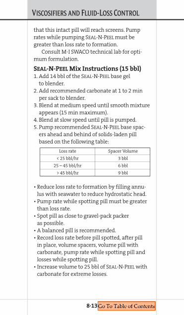
VISCOSIFIERS AND FLUID-LOSS CONTROL
that this intact pill will reach screens. Pumprates while pumping SEAL-N-PEEL must begreater than loss rate to formation.
Consult M-I SWACO technical lab for opti-mum formulation.
SEAL-N-PEEL Mix Instructions (15 bbl)1. Add 14 bbl of the SEAL-N-PEEL base gel
to blender.2. Add recommended carbonate at 1 to 2 min
per sack to blender.3. Blend at medium speed until smooth mixture
appears (15 min maximum).4. Blend at slow speed until pill is pumped.5. Pump recommended SEAL-N-PEEL base spac-
ers ahead and behind of solids-laden pillbased on the following table:
• Reduce loss rate to formation by filling annu-lus with seawater to reduce hydrostatic head.
• Pump rate while spotting pill must be greaterthan loss rate.
• Spot pill as close to gravel-pack packeras possible.
• A balanced pill is recommended.• Record loss rate before pill spotted, after pill
in place, volume spacers, volume pill withcarbonate, pump rate while spotting pill andlosses while spotting pill.
• Increase volume to 25 bbl of SEAL-N-PEEL withcarbonate for extreme losses.
8·13
Loss rate Spacer Volume
< 25 bbl/hr 3 bbl
25 – 45 bbl/hr 6 bbl
> 45 bbl/hr 9 bbl

VISCOSIFIERS AND FLUID-LOSS CONTROL
OPTIBRIDGE PILLSOPTIBRIDGE pills are designed using proprietarysoftware that examines data from the targetedformation, including maximum pore size open-ing and permeability and combines that inputwith the bridging-particle information.OPTIBRIDGE software automatically generates atarget line of the optimum blend of particlesthat will effectively minimize solids and filtrateinvasion. Once the optimum blend is known,the ratio of bridging materials is matched tothe formation characteristics. A fit-for-purposeblend made of either calcium carbonate or saltwill effectively seal the formation.
Sized-Salt PillsSized-salt pills can be used in a broad densityspectrum ranging from 10.5 to 17.0 dependingon the base brine and concentration of bridgingsolids utilized. Typically salt pills are mixed insaturated sodium chloride brine, but they canalso be used with potassium chloride, calciumchloride, sodium bromide, calcium bromide andzinc bromide as long as the base brine is satu-rated with respect to sodium chloride to preventsolubilizing the sized sodium chloride bridgingsolids. These fluid-loss control systems have aunique synergistic blend of polymers whichcreate optimum rheological and suspensionproperties providing long-term stability, andcontingent to the thermal extender packageused they can withstand bottomhole temper-atures up to 325° F (162.7° C).
Optimized particle-size distributions sealformations and completion screens over a wide
8·14

VISCOSIFIERS AND FLUID-LOSS CONTROL
range of permeability minimizing formationdamage. Sized-salt pills can be removed with anacid soak to destroy the internal polymers andan unsaturated (with respect to sodium chlo-ride) brine to dissolve the sodium chloridebridging agents. Consult M-I SWACO technicallab for optimum pill and breaker formulation.
Bridgesal Ultra SuperfineMixing ProcedureBefore adding Bridgesal^ Ultra Superfine, thebase brine must be saturated with respect tosodium chloride to prevent the bridging saltfrom being dissolved. Refer to sodium chloridesaturation tables for each respective base brine.
Mixing Instructions1. Start with the desired amount of brine in a
clean slugging pit or mixing tank. 2. Add ∑ can (2.5 gal [9.46 L]) of DEFOAM 2* for
every 20 bbl of fluid.3. If necessary, add the required amount of
EVAPORATED SALT through the mud hopperat 2 to 3 min per sack for saturation withrespect to NaCl.
Note: After saturating the brine withsodium chloride, it should be filtered to ensurethe removal of any particles above 44 microns.If Ultrasal 5 or 10 is used to saturate the brine,no filtering is required.4. Add the required amount of Bridgesal Ultra
Superfine (50 to 70 lb/bbl [22.6 to 31.8 kg])through the mud hopper at 6 to 8 min persack. Add additional DEFOAM 2 as needed tocontrol foaming.
8·15
^Bridgesal is a mark of Texas Brine Corporation.

VISCOSIFIERS AND FLUID-LOSS CONTROL
5. If additional FL-7 Plus^ is needed add througha hopper at 6 to 8 min per sack.
6. If CaCl2 brine is used, add 2 to 5 lb/bbl (0.9 to2.27 kg) of pH buffer through a hopper at 3to 4 min per sack.
7. Allow the pill to agitate for 30 to 45 min priorto pumping downhole.
Note: If a mud hopper is not available, addall products at maximum agitation as possiblewhile circulating through a pump. If the BHTis above 250° F (121.1° C), contact an M-I SWACOrepresentative.
Bridgesal Ultra Mixing ProcedureBefore adding Bridgesal Ultra, the base brinemust be saturated with respect to sodium chlo-ride to prevent the bridging salt from beingdissolved. Refer to sodium chloride saturationtables for each respective base brine.
Mixing Instructions1. Start with the desired amount of brine in a
clean slugging pit or mixing tank. 2. Add ∑ can (2.5 gal [9.46 L]) of DEFOAM 2 for
every 20 bbl of fluid. 3. If necessary, add the required amount of
EVAPORATED SALT through the mud hopperat 2 to 3 min per sack for saturation withrespect to NaCl.
4. Add the required amount of Bridgesal Ultra(50 to 60 lb/bbl [22.6 to 27.2 kg]) throughthe mud hopper at 6 to 8 min per sack.Add additional DEFOAM 2 as needed tocontrol foaming.
5. If additional FL-7 Plus is needed add through ahopper at 6 to 8 min per sack.
8·16
^FL-7 Plus is a mark of Texas Brine Corporation.
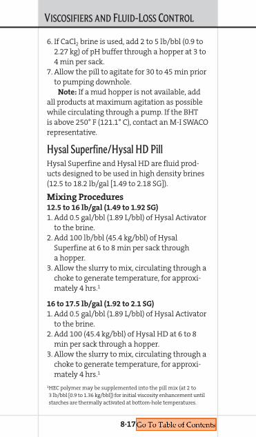
VISCOSIFIERS AND FLUID-LOSS CONTROL
6. If CaCl2 brine is used, add 2 to 5 lb/bbl (0.9 to2.27 kg) of pH buffer through a hopper at 3 to4 min per sack.
7. Allow the pill to agitate for 30 to 45 min priorto pumping downhole.
Note: If a mud hopper is not available, addall products at maximum agitation as possiblewhile circulating through a pump. If the BHTis above 250° F (121.1° C), contact an M-I SWACOrepresentative.
Hysal Superfine/Hysal HD PillHysal Superfine and Hysal HD are fluid prod-ucts designed to be used in high density brines(12.5 to 18.2 lb/gal [1.49 to 2.18 SG]).
Mixing Procedures12.5 to 16 lb/gal (1.49 to 1.92 SG)
1. Add 0.5 gal/bbl (1.89 L/bbl) of Hysal Activatorto the brine.
2. Add 100 lb/bbl (45.4 kg/bbl) of HysalSuperfine at 6 to 8 min per sack througha hopper.
3. Allow the slurry to mix, circulating through achoke to generate temperature, for approxi-mately 4 hrs.1
16 to 17.5 lb/gal (1.92 to 2.1 SG)
1. Add 0.5 gal/bbl (1.89 L/bbl) of Hysal Activatorto the brine.
2. Add 100 (45.4 kg/bbl) of Hysal HD at 6 to 8min per sack through a hopper.
3. Allow the slurry to mix, circulating through achoke to generate temperature, for approxi-mately 4 hrs.1
1HEC polymer may be supplemented into the pill mix (at 2 to3 lb/bbl [0.9 to 1.36 kg/bbl]) for initial viscosity enhancement untilstarches are thermally activated at bottom-hole temperatures.
8·17
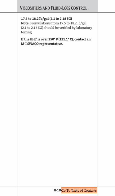
VISCOSIFIERS AND FLUID-LOSS CONTROL
17.5 to 18.2 lb/gal (2.1 to 2.18 SG)
Note: Formulations from 17.5 to 18.2 lb/gal(2.1 to 2.18 SG) should be verified by laboratorytesting.
If the BHT is over 250° F (121.1° C), contact an
M-I SWACO representative.
8·18
Chapter 9CORROSION INHIBITION AND PACKER FLUIDS
COMPLETION FLUIDSMANUAL
9. CORROSIONINHIBITION
ANDPACKERFLUIDS
CORROSION INHIBITION AND PACKER FLUIDS
M-I SWACO offers corrosion inhibitors, oxygenscavengers and biocides to minimize or preventcorrosion in completion, workover and reservoirdrill-in fluid systems.
SAFE-CORSAFE-COR* is an amine-based corrosion inhibitorthat forms an inert film on downhole oilfieldtubulars. SAFE-COR should be used as the pri-mary inhibitor for all non-zinc bromide packer-fluid applications in which Corrosion ResistantAlloys (CRA) material is used for productiontubing and the maximum temperature is lessthan 350° F (177° C). The standard inhibitortreatment of 55 U.S. gal/100 bbl (13.1 L/m3)should be applied. An oxygen scavenger shouldbe added at standard dosage and biocide whenappropriate (less than saturated salt). Formate-based brines for high-temperature applicationsdo not strictly require a chemical corrosioninhibitor in the presence of CRAs. In such cases,a pH buffer, such a potassium carbonate, shouldbe added to reduce the rate of corrosion. Oxygenscavenger and/or biocide may be added in caseswhere under-saturated formate brines are used.
SAFE-COR 220XSAFE-COR 220X is a brine-soluble amide-corrosion inhibitor comprising a solution ofglycoside-amide in water. Typical treatmentlevel is 1 to 1.3% by volume (55 gal/100 bbl[13.1 L/m3]). SAFE-COR 220X is recommended forCO2 and H2S environments when the tempera-ture is <250° F (<121° C).
9·1

CORROSION INHIBITION AND PACKER FLUIDS
SAFE-COR ESAFE-COR E corrosion inhibitor is a modifiedamine-type additive formulated to protect alloilfield tubular goods, for solubility in clearbrine completion fluids and to minimize envi-ronmental impact. It helps prevent generalcorrosion attack on casing, tubing and down-hole tools in contact with completion brines.SAFE-COR E is a highly concentrated productdesigned and packaged for use in solids-freeworkover and completion brines.
SAFE-COR HTSAFE-COR HT is a high-temperature corrosioninhibitor effective in ZnBr2 solutions. It is asolution of an inorganic sulfur salt in water.Typical treatment level is 0.33% by volume(55 gal/400 bbl [3.27 L/m3]). SAFE-COR HT,which forms a protective, very thin film ofiron-sulfide scale, should be used only for
carbon-steel tubulars.
SAFE-SCAV NASAFE-SCAV* NA is a bisulfite-based oxygenscavenger for non-calcium brines. Typical treat-ment level is 0.025% by volume (1 gal/100 bbl[0.24 L/m3]).
SAFE-SCAV CASAFE-SCAV CA is an oxygen scavenger forcalcium-based brines. An organic salt. Typicaltreatment level is 15 lb/100 bbl (0.43 kg/m3).
9·2
CORROSION INHIBITION AND PACKER FLUIDS
SAFE-SCAV HSSAFE-SCAV HS is a brine-soluble, amine-basedhydrogen sulfide scavenger. Typical treatmentlevel is 0.025% by volume (1 gal/100 bbl[0.24 L/m3]).
Application of SAFE-COR CorrosionInhibitors in Packer FluidsCorrosion inhibition is recommended whenclear-brine completion fluids are used aspacker fluids. Corrosion rate data for non-zincbromide brines suggest these brines are notgenerally corrosive. Most non-zinc bromidebrines show an average corrosion rate of lessthan 5 milli-inches per year (m.p.y.) to oilfieldgrade carbon steel at temperatures up to 350° F(177° C). Zinc bromide fluids are inherentlyacidic. These brines can be very corrosive ifnot adequately inhibited.
Organic filming inhibitors, such as SAFE-COR,SAFE-COR E and SAFE-COR 220X, act by forminga protective barrier or film on the surface ofthe metal. Film-forming inhibitors consist of apolar group and a long, non-polar (hydrocarbon)chain. The polar group contains what is referredto as a heteroatom, i.e., oxygen, phosphorous,sulfur or more typically, nitrogen. The nitrogencontaining molecules are most typically amines.The molecular structure of these amines is suchthat “free” electrons are capable of forming achemisorptive bond with metallic iron. Thisbond holds the molecular “head” onto the sur-face of the metal and the hydrocarbon “tail”acts as a “film” — thus the name “filmingamine.” The strength of the adsorptive bond
9·3
CORROSION INHIBITION AND PACKER FLUIDS
and how long this bond lasts depends on theenvironment, i.e., the molecular structure of thechemical, the solubility of the material in theaqueous medium (brine), movement of fluidacross the surface, physical disruption, etc.
The amines used for packer-fluid applica-tions are much different than those used inproduction applications. The amines in packerfluids must be completely soluble in the brine,whereas most production chemical amines areoil soluble or water dispersible. The ability ofa packer-fluid amine to maintain its adsorbedlayer is greatly enhanced by the fact that oncein place, no aggressive movement of fluid occurs,nor does a concentration gradient exist to allowdiffusive forces to act. The fact that it is a closedsystem, the amine is not chemically reacted ordestroyed as part of the filming process and thebrine contains a relatively high concentration ofamine, self “healing” can occur and the filmshould last indefinitely.
SAFE-COR HT is an inorganic inhibitor thatacts at the anodic site, reacting with the oxi-dized iron by a chemical reaction forminga thin, protective layer. SAFE-COR HT is athiocyanate-based inhibitor and, like othersulfur-based products, should not be usedwith chrome alloys.
The primary chemical species directlyinvolved in the corrosion process include acidand oxygen. Besides the alkaline inhibitor, cor-rosion inhibition should include: 1) eliminatingoxygen in the brine, and 2) increasing pH wherefeasible. Other species such as sulfur, chloridesand certain bacteria also impact the corrosionprocess. Bacteriacides should be added to those
9·4
CORROSION INHIBITION AND PACKER FLUIDS
fluid systems that would allow bacteria to grow.Although not specific, brines with a density lessthan about 11.0 lb/gal (1.32 SG) should be treatedwith biocide for packer-fluid use.
CRA TubingCorrosion Resistant Alloys (CRA) have beenused extensively in wellbore construction overthe last couple of decades. With the develop-ment of deeper, hotter and higher-pressuredwells, new generation CRAs are being producedthat possess greater Yield Strength (YS) thanprevious versions. For example, “Super” and“Hyper” grade 13% chromium stainless steels(13-Cr) achieve yield strengths of 95 to 110 ksi andabove, by alloying the iron-chromium withhigh percentages of molybdenum, nickel andother alloying elements. These higher strengthsare more prone to Stress Corrosion Cracking(SCC) than their lower-strength counterparts.
As their name suggests, CRA tubulars anddownhole equipment are generally resistantto corrosive environments and each is selectedfor an application for which it is best suited.Depending on the amount and type of alloyingelements and homogeneity of the microstruc-ture, localized corrosion such as pitting canlead to sudden and catastrophic cracking fail-ure. 13-Cr stainless steel is the most commonMartensitic Stainless Steel (MSS) used for itsresistance to sweet acid-gas (CO2) corrosion,however, these materials are susceptible tolocalized H2S attack. For sour-gas corrosion,higher-chrome alloys, such as the DuplexStainless Steels (DSS) of 22%-Cr, 25%-Cr and
9·5

CORROSION INHIBITION AND PACKER FLUIDS
9·6
28%-Cr, or even pure nickel-chrome alloys, suchas Inconel and Hastelloy ,̂ are used. Althoughmore resistant to H2S, these higher alloys areprone to hydrogen embrittlement under certainconditions. Regardless of the metallurgy, thehigher-strength materials are always moreprone to environmentally induced SCC thanlower-strength materials or equal-strength low-alloy, carbon steel. SCC is a corrosion phenome-non related to the metallurgy, internal andexternal stresses and the corrosiveness of theenvironment in which the metal resides.
Thiocyanate (SCN–) decomposes at hightemperature and forms H2S. Consequently, theuse of a thiocyanate corrosion inhibitor, such asSAFE-COR HT with 13-Cr or DSS material is usedfor tubing is not recommended.
The other important environment identifiedas increasing the risk of SCC with CRA materialsis chloride content. Chloride Stress CorrosionCracking (CSCC) of high-strength 13-Cr and even22-Cr DSS has been reported. Whereas, in mostof these reported cases, sulfur or thiocyanatehas also been identified in the packer fluid, therole of the chloride ion (Cl–) should not beoverlooked. At least in some high-strength13-Cr cases, chlorides were implicated in CSCCwithout evidence of sulfur of any type. For thisreason, M-I SWACO recommends using a chlo-ride-free packer fluid when it is placed behind>80 ksi YS 13-Cr steel at temperatures greaterthan about 200° F (93° C).
^Mark of Haynes International, Inc.

CORROSION INHIBITION AND PACKER FLUIDS
9·7
Flu
id T
yp
eD
en
sity
Te
mp
era
ture
Me
tall
urg
yIn
hib
ito
r P
kg
.C
on
cen
tra
tio
n
Wat
er8.
334
lb/g
al<3
50°
FSt
and
ard
/CR
ASA
FE-C
OR
55 g
al/1
00 b
bl(9
98 k
g/m
3 )(<
176°
C)
(13.
1 L/
m3 )
S AFE
-SC
AV
NA
5 ga
l/50
0 bb
l(.2
38 L
/m3 )
Glu
te 2
55
gal/
500
bbl
(.238
L/m
3 )C
aust
ic S
oda
To p
H 9
.5
Wat
er8.
334
lb/g
al>3
50°
FSt
and
ard
/CR
AG
lute
25
5 ga
l/50
0 bb
l(>
176°
C)
(.238
L/m
3 )C
aust
ic S
oda
To p
H 9
.5
Form
ates
All
den
siti
es<4
00°
FSt
and
ard
/CR
AK
car
bon
ate
5 lb
/bbl
(<20
4° C
)(1
4.3
kg/m
3 )
Con
tin
ues
on
nex
t p
age
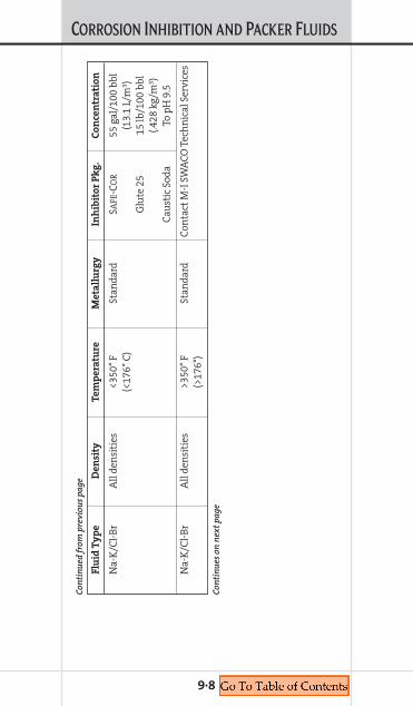
CORROSION INHIBITION AND PACKER FLUIDS
9·8
Flu
id T
yp
eD
en
sity
Te
mp
era
ture
Me
tall
urg
yIn
hib
ito
r P
kg
.C
on
cen
tra
tio
n
Na-
K/C
l-B
rA
ll d
ensi
ties
<350
° F
Stan
dar
dSA
FE-C
OR
55 g
al/1
00 b
bl(<
176°
C)
(13.
1 L/
m3 )
Glu
te 2
515
lb/1
00 b
bl(.4
28 k
g/m
3 )C
aust
ic S
oda
To p
H 9
.5
Na-
K/C
l-B
rA
ll d
ensi
ties
>350
° F
Stan
dar
dC
onta
ct M
-I S
WA
CO
Tec
hn
ical
Ser
vice
s(>
176°
)
Con
tin
ues
on
nex
t p
age
Con
tin
ued
from
pre
viou
s p
age
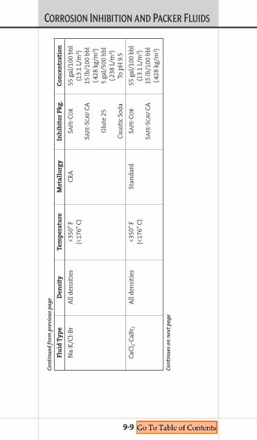
CORROSION INHIBITION AND PACKER FLUIDS
9·9
Flu
id T
yp
eD
en
sity
Te
mp
era
ture
Me
tall
urg
yIn
hib
ito
r P
kg
.C
on
cen
tra
tio
n
Na-
K/C
l-B
rA
ll d
ensi
ties
<350
° F
CR
ASA
FE-C
OR
55 g
al/1
00 b
bl(<
176°
C)
(13.
1 L/
m3 )
S AFE
-SC
AV
CA
15 lb
/100
bbl
(.428
kg/
m3 )
Glu
te 2
55
gal/
500
bbl
(.238
L/m
3 )C
aust
ic S
oda
To p
H 9
.5
CaC
l 2-C
aBr 2
All
den
siti
es<3
50°
FSt
and
ard
SAFE
-CO
R55
gal
/100
bbl
(<17
6° C
)(1
3.1
L/m
3 )S A
FE-S
CA
VC
A15
lb/1
00 b
bl(.4
28 k
g/m
3 )
Con
tin
ued
from
pre
viou
s p
age
Con
tin
ues
on
nex
t p
age
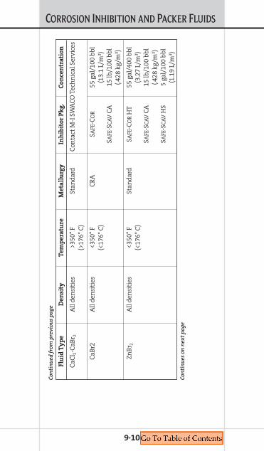
CORROSION INHIBITION AND PACKER FLUIDS
9·10
Flu
id T
yp
eD
en
sity
Te
mp
era
ture
Me
tall
urg
yIn
hib
ito
r P
kg
.C
on
cen
tra
tio
n
CaC
l 2-C
aBr 2
All
den
siti
es>3
50°
FSt
and
ard
Con
tact
M-I
SW
AC
O T
ech
nic
al S
ervi
ces
(>17
6° C
)
CaB
r2A
ll d
ensi
ties
<350
° F
CR
ASA
FE-C
OR
55 g
al/1
00 b
bl(<
176°
C)
(13.
1 L/
m3 )
S AFE
-SC
AV
CA
15 lb
/100
bbl
(.428
kg/
m3 )
ZnB
r 2A
ll d
ensi
ties
<350
° F
Stan
dar
dSA
FE-C
OR
HT
55 g
al/4
00 b
bl(<
176°
C)
(3.2
7 L/
m3 )
S AFE
-SC
AV
CA
15 lb
/100
bbl
(.428
kg/
m3 )
S AFE
-SC
AV
HS
5 ga
l/10
0 bb
l(1
.19
L/m
3 )
Con
tin
ued
from
pre
viou
s p
age
Con
tin
ues
on
nex
t p
age
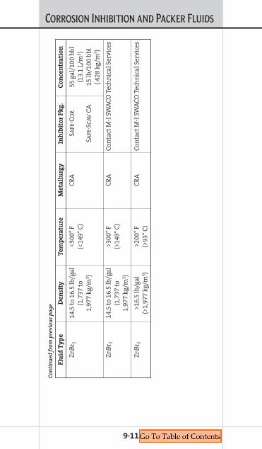
CORROSION INHIBITION AND PACKER FLUIDS
9·11
Flu
id T
yp
eD
en
sity
Te
mp
era
ture
Me
tall
urg
yIn
hib
ito
r P
kg
.C
on
cen
tra
tio
n
ZnB
r 214
.5 t
o 16
.5 lb
/gal
<300
° F
CR
ASA
FE-C
OR
55 g
al/1
00 b
bl(1
,737
to
(<14
9° C
)(1
3.1
L/m
3 )1,
977
kg/m
3 )SA
FE-S
CA
VC
A15
lb/1
00 b
bl(.4
28 k
g/m
3 )
ZnB
r 214
.5 t
o 16
.5 lb
/gal
>300
° F
CR
AC
onta
ct M
-I S
WA
CO
Tec
hn
ical
Ser
vice
s(1
,737
to
(>14
9° C
)1,
977
kg/m
3 )
ZnB
r 2>1
6.5
lb/g
al>2
00°
FC
RA
Con
tact
M-I
SW
AC
O T
ech
nic
al S
ervi
ces
(>1,
977
kg/m
3 )(>
93°
C)
Con
tin
ued
from
pre
viou
s p
age
Chapter 10FILTRATION
COMPLETION FLUIDSMANUAL
10. FILTRATION
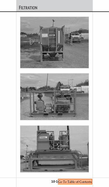
FILTRATION
10·1

FILTRATION
Filtration is a process used to remove suspendedmaterials from liquids. In completion fluids, thesuspended materials can include weightingagents, drill solids, perforating debris, sand,scale, rust, etc. These suspended materials, ifleft in the liquid, can damage the permeabilityof the formation.
By selecting the proper filtration method,fluids can remain clean and non-damagingand the process can be accomplished in acost-effective manner.
Two types of filtration are used in comple-tion and workover operations:
1. Depth filtration utilizing a filter press withrecessed chamber plates and DE.
2. Surface filtration-using cartridges.In most cases the combination of these units
provides the most efficient filtration package.
Equipment Design Diatomaceous Earth (DE)
Filtration System A Diatomaceous Earth (DE) filtration systemincludes a downstream double-pod cartridgefiltration unit, which acts as a polishing unitand a guard unit against DE bleed-through.• The plate and frame unit should have O-ring
gasket plates to eliminate leakage whilefiltering.
• All drain ports in the drip pan beneath theplates of the filter press should be plugged toensure all of the filter cake and fluid trappedbetween the plates is collected when the pressis opened. Fluid can then be salvaged.
10·2
FILTRATION
• Prior to the regeneration process, proper blow-down with air is required to remove fluidtrapped in the filter cake within the recessedchambers of the plates and within the mani-fold system of the press.
• All filtration units should have an apronrunning the full length of the drip pan areato above the plates on both sides of the pressto eliminate potential spill while the pressis opened for regeneration of DE. Any fluiddropped into the drip pan of the press ispumped (diaphragm) into a MPT tank or othersuitable holding vessel. This tank is checked forreclaimable fluid, which can be decanted intoanother MPT tank or into the rig’s active system.
• All hoses on the filtration unit should haveball valves that can be closed or opened duringoperation. This allows the operator to closethe valve at the disconnect point, saving fluidwhen repositioning equipment, rigging up orrigging down. The trapped fluid from the hosesis evacuated back into the pit system, elimi-nating spillage and offer maximum recovery.Portable troughs at the disconnect points arerecommended.
Pod Cartridge Filter UnitTypically, these units are “dual pod” construc-tions with interconnecting piping for eitherparallel, in-series or bypass configuration. Thevessels or housings hold disposable cartridges.The number of cartridges per vessel may varyper manufacturer. This equipment is desirableon lightweight fluids and small inexpensivebrine cleanups. Also, the lightweight and small
10·3

FILTRATION
footprint makes cartridge filtration more favor-able over larger DE units if the cartridge unitcan maintain the parameters of filtration(cleanliness, pump rate, density).
10·4
Type of Fluid Expected Filtration PackageComments Solids Loading Required
Fresh seawater Low 2- or 10-micronDump on return absolute cartridge
from well filters
Light brine Low 2- and/or Dump on return 10-micron
from well or pre-filterfilter for reuse, cartridge filteri.e., NaCl/KCl
Medium-weight Low 2- and/orbrine filter for 10-micron
reuse, i.e., CaCl2 pre-filtercartridge filter
Medium-weight High Pre-filterbrine filter for 10-micron
reuse, i.e., CaCl2 and/or 2-micronabsolute cartridge
filter or DEsystem and 2-or 10-micron
cartridge filter
Heavy-weight Low/High DE system withbrine filter for 2/10 cartridge
reuse, i.e., NaBr, filtersCaBr2, K formate
Very heavy-weight High DE system withbrine, i.e., ZnBr2 2/10 cartridge
filters
Filtration Requirement Summary
FILTRATION
MI SWACO Filtration Equipment and Materials
All filtration presses are manufactured withbackup hydraulic systems. The filter press isequipped with dual-hydraulic pumps. Filterplates are gasket sealed. Extra filter clothes aresent out to assure operations with no downtime.
M-I SWACO maintains 1,600-ft2 (148.6-m2),1,500-ft2 (139.4-m2), 1,135-ft2 (105.4-m2), 800-ft2
(74.3-m2), and 600-ft2 (55.7-m2) filter presses.All presses are designed to be stackable. AllM-I SWACO slurry skids are equipped withdual downstream guard units equipped tohold five (5) platinum cartridges per pod.The unique design of platinum cartridges usessegregated flow channels and flow chambers tomaximize the effective surface area of pleatedfilter media within a 6∏-in. (158.8-mm) ODcartridge.
One platinum series cartridge filter isdesigned to replace up to ten standard 2.5-in.(63.5-mm) OD standard cartridges of similarlength. Available in a variety of media, this car-tridge can be constructed with metal end capsand cores for high-temperature applications.
With maximum recommended flow rates of100 gal/min (378.5 L/min) this platinum seriesfilter is the solution to achieving optimum per-formance while minimizing filtration cost.
M-I SWACO also maintains stand-alone dualpod units. These units can be loaded with everysize filter available.
The M-I SWACO 65-bbl blending tanks havetwo impeller blades to assure proper blendingaction. The tanks are equipped with chemical
10·5

FILTRATION
hoppers with jetted action. They have 6-in.(152.4-mm) slope discharges for properdischarge to connect for tank drainage.
M-I SWACO utilizes turbo shear units toshear viscous pills and blend chemicals.Shear pumps are powered with a skid-mounted diesel engine.
M-I SWACO has 3-bbl wet tanks with air-powered motors.
M-I SWACO provides DE bulk tanks that holdone (1) ton of Diatomaceous Earth. The tankshave safe holding racks mounted on top of thefiltration-slurry skids for safe operations. Thesetanks are equipped with air-operated vibrators.
Pallet boxes that hold two pallets can beloaded from the top and sides. These boxes keepproducts and equipment environmentally safe.
M-I SWACO stocks three grades of diatoma-ceous material: fine grade, medium grade andcoarse grade. DE is available in bulk tanks, 50-lb(22.7-kg) sacks at 18 sacks per pallet and 25-lb(11.3-kg) sacks at 40 sacks per pallet.
M-I SWACO equipment has certified slingsand uses shackles for safe transfer of equipment.Hoses have stainless steel connections withsafely lock ears and are pressure tested and cer-tified. Hoses are labeled for easy identification.
10·6
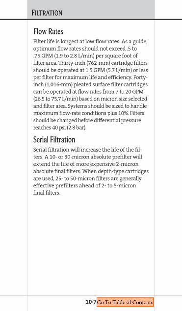
FILTRATION
10·7
Flow RatesFilter life is longest at low flow rates. As a guide,optimum flow rates should not exceed .5 to.75 GPM (1.9 to 2.8 L/min) per square foot offilter area. Thirty-inch (762-mm) cartridge filtersshould be operated at 1.5 GPM (5.7 L/min) or lessper filter for maximum life and efficiency. Forty-inch (1,016-mm) pleated surface filter cartridgescan be operated at flow rates from 7 to 20 GPM(26.5 to 75.7 L/min) based on micron size selectedand filter area. Systems should be sized to handlemaximum flow-rate conditions plus 10%. Filtersshould be changed before differential pressurereaches 40 psi (2.8 bar).
Serial FiltrationSerial filtration will increase the life of the fil-ters. A 10- or 30-micron absolute prefilter willextend the life of more expensive 2-micronabsolute final filters. When depth-type cartridgesare used, 25- to 50-micron filters are generallyeffective prefilters ahead of 2- to 5-micronfinal filters.
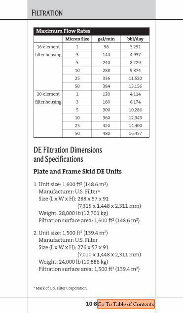
FILTRATION
10·8
DE Filtration Dimensions and SpecificationsPlate and Frame Skid DE Units
1. Unit size: 1,600 ft2 (148.6 m2) Manufacturer: U.S. Filter^Size (L x W x H): 288 x 57 x 91
(7,315 x 1,448 x 2,311 mm)Weight: 28,000 lb (12,701 kg)Filtration surface area: 1,600 ft2 (148.6 m2)
2. Unit size: 1,500 ft2 (139.4 m2) Manufacturer: U.S. FilterSize (L x W x H): 276 x 57 x 91
(7,010 x 1,448 x 2,311 mm)Weight: 24,000 lb (10,886 kg)Filtration surface area: 1,500 ft2 (139.4 m2)
Micron Size gal/min bbl/day
16-element 1 96 3,291
filter housing 3 144 4,937
5 240 8,229
10 288 9,874
25 336 11,520
50 384 13,156
20-element 1 120 4,114
filter housing 3 180 6,174
5 300 10,286
10 360 12,343
25 420 14,400
50 480 16,457
Maximum Flow Rates
^Mark of U.S. Filter Corporation.
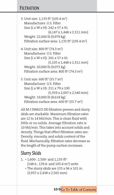
FILTRATION
3. Unit size: 1,135 ft2 (105.4 m2) Manufacturer: U.S. FilterSize (L x W x H): 242 x 57 x 91
(6,147 x 1,448 x 2,311 mm)Weight: 22,000 lb (9,979 kg)Filtration surface area: 1,135 ft2 (105.4 m2)
4. Unit size: 800 ft2 (74.3 m2) Manufacturer: U.S. FilterSize (L x W x H): 201 x 57 x 91
(5,105 x 1,448 x 2,311 mm)Weight: 20,000 lb (9,072 kg)Filtration surface area: 800 ft2 (74.3 m2)
5. Unit size: 600 ft2 (55.7 m2) Manufacturer: U.S. FilterSize (L x W x H): 211 x 79 x 100
(5,359 x 2,007 x 2,540 mm)Weight: 19,000 lb (8,618 kg)Filtration surface area: 600 ft2 (55.7 m2)
All M-I SWACO DE filtration presses and slurryskids are stackable. Maximum filtration ratesare 12 to 14 bbl/min. This is clean fluid withlittle or no solids. Average filtration rate is10 bbl/min. This takes into account solids anddensity. Things that effect filtration rates are:Density, viscosity, and solids content of thefluid. Mechanically, filtration rates decrease asthe length of the pump suction increases.
Slurry Skids1. • 1,600-, 1,500- and 1,135-ft2
(148.6-, 139.4- and 105.4-m2) units• The slurry skids are 155 x 96 x 101 in.
(3,937 x 2,438 x 2,565 mm)
10·9
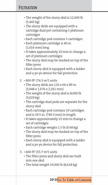
FILTRATION
10·10
• The weight of the slurry skid is 12,000 lb(5,443 kg)
• The slurry skids are equipped with acartridge dual pot containing 5 platinumcartridges
• Each cartridge pod contains 5 cartridges• Each platinum cartridge is 40 in.
(1,016 mm) long• It takes approximately 10 min to change a
set of platinum cartridges• The slurry skid may be stacked on top of the
filter press• Each slurry skid is equipped with a ladder
and a yo-yo device for fall protection
2. • 800-ft2 (74.3-m2) units• The slurry skids are 120 x 66 x 89 in.
(3,048 x 1,676 x 2,261 mm)• The weight of the slurry skid is 8,000 lb
(3,629 kg)• The cartridge dual pods are separate for the
slurry skid• Each cartridge pod contains 19 cartridges
and is 29.5 in. (749.3 mm) in length• It takes approximately 15 min to change a
set of cartridges• Each cartridge weighs 1.5 lb (0.68 kg)• The slurry skid may be stacked on top of the
filter press• Each slurry skid is equipped with a ladder
and a yo-yo device for fall protection
3. • 600-ft2 (55.7-m2) units• The filter press and slurry skid are built
into one skid• The total weight 19,000 lb (8,618 kg)

FILTRATION
• The dimensions are 211 x 79 x 100 in. (5,359 x 2,007 x 2,540 mm)
• Each cartridge pod contains 19 cartridgesand is 29.5 in. (749.3 mm) in length
• It takes approximately 15 min to change aset of cartridges
• Each cartridge weighs 1.5 lb (0.68 kg)
Pump Skids1. Pump skid for all units:
Engine type: Detroit 353/371-in.3 100hpPump manufacturer: Gorman-Rupp^UBB60-BPump size: 4 x 4 in. (101.6 x 101.6 mm)self-priming centrifugalOutput: 14.5 bbl/min at 75 psi (5.2 bar)Skid size (L x W x H): 10 ft 6 in. x 3 ft x 5 ft 5 in.
(3m 152.4 mm x 0.91 m x1.5 m 127 mm)
Weight: 6,000 lb (2,722 kg)
Miscellaneous Equipment and SafetyDE Bulk Tanks• Tank size (L x W x H): 48 in. x 60 ft x 90 in.
(1,219 mm x 18.3 m x2,286 mm)
• DE bulk tanks hold 1,500 lb (680 kg) ofDE Material
• DE bulk tanks weigh 850 lb (386 kg) empty
Operational Applications• DE averages 1 lb/ft2 (4.88 kg/m2)• Filtration cycles average 1 bbl/ft2 (1.71 kg/m2).
This also depends on solids content.
10·11
^Mark of Gorman-Rupp Company.

FILTRATION
Chemical Injection Pump• Type: Air• Size: 2 in. (50.8 mm)• Manufacturer: Versa-Matic^
(anti-freeze device)
Hose Basket• Size (L x W x H): 22 x 4 x 3 (6.7 x 1.2 x 0.9 m)• Weight: 4,500 lb (2,041 kg)• Feet of hoses: 120 ft of 4-in.
(36.6 m of 101.6-mm) suction hose and240 ft of 3-in. (73.2 m of 76.2-mm)discharge hose
• Other hoses: 40 ft of 2-in. (12.2 m of 50.8-mm) hose and300 ft of 1-in. (91.4 m of 25.4)-mm) hose
Waste Pump• Type: Air• Size: 3 in. (76.2 mm)• Manufacturer: Versa-Matic
(anti-freeze device)
Safety Considerations• Ladders are provided with our units• Yo-yo fall protection devices are included• Hand rails are provided with slurry skids
DE bulk tanks reduce risk of back injuries.
For safe working and operating conditions,M-I SWACO requires 3 ft (0.9 m) of clearancearound its equipment.
10·12
^Mark of Versa-Matic Pump Company.
Chapter 11SPEEDWELL TOOLS
COMPLETION FLUIDSMANUAL
11. SPEEDW
ELLTOOLS
SPEEDWELL TOOLS
To create synergy between chemicals and toolswhen cleaning a marine riser and wellboreM-I SWACO has integrated the SPEEDWELL
cleanup tool product line into its total wellborecleanup package. Following are descriptionsand specifications of the primary tools andsupport programs in the SPEEDWELL portfolio.
OPTISPEED* tool utilization program — AnExcel^ spreadsheet with four variables: (1) aver-age spread cost per day, (2) short-trip rate in feetor meters per hour, (3) tool cost and (4) toolmakeup and breakout time. If the operator isgoing to short trip the scraper brush tools in thewellbore, the OPTISPEED tool utilization programwill calculate not only the cost of each incremen-tal scraper brush tool in each casing section, butapproximate placement of the tools as well.
SPEEDDRAW* tool draw program — For gener-ating a well diagram that shows the recom-mended cleanup tools and the recommendedtool placement based on the output data fromthe OPTISPEED tool utilization program.
Short tripping tools — Used to pull out of thehole with the workstring far enough to brushand scrape the areas in the casing or linerbeyond the reach of the previous scraper brushtool. Afterwards, run back to the bottom ofthe hole to ensure the removal of any debrisadhered to the inside of the pipe.
Scraper — A tool that scrapes the inside of thecasing or liner(s) to remove cement sheath,scale and other debris.
11·1
^Mark of Microsoft Corporation.
SPEEDWELL TOOLS
Brush — A tool that brushes and disturbs mudsolids and other debris adhered to the inside ofthe casing or liner(s).
SPEEDWELL PUP* tool — A proprietary modularcasing cleaning tool that includes a tool jointat the top for ease of handling and safety. ThePUP tool can be assembled with four carriersfor brushes, scrapers or magnets.
SPEEDWELL SHORTY* tool — A cost-effective,proprietary modular casing cleaning tool. Asopposed to the four carriers of the PUP Tool,the SHORTY tool has two or three carriers.
Downhole debris filtration tool — A tooldesigned to filter debris and particulate fromthe fluid toward the bottom of the wellbore.
Boot Basket — Another term for a junk basketand is used to catch debris that is dislodgedfrom the wellbore, BOP stack and/or riser.
Jetting Tool — Used to dislodge debris by jet-ting or water blasting the inside of the BOPstack and/or riser.
Riser Brush — A specially designed tool tobrush the inside of marine risers.
Magnets — Used to remove ferrous debris fromthe wellbore.
Chemical cleaning — The use of chemicalsto clean the inside of casings, liners andmarine risers.
Mechanical cleaning — The use of cleanuptools to clean the inside of casings, liners andmarine risers.
Total riser/wellbore cleanup — Using chemicaland cleanup tools together with optimizedhydraulics to clean the inside of casings, liners
11·2
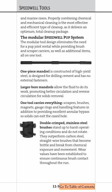
SPEEDWELL TOOLS
and marine risers. Properly combining chemicaland mechanical cleaning is the most effectiveand efficient type of cleanup, as it delivers anoptimum, total cleanup package.
The modular SPEEDWELL PUP SystemThe modular tool design eliminates the needfor a pup joint rental while providing brushand scraper carriers, as well as additional items,all on one tool.
One-piece mandrel is constructed of high-yieldsteel, is designed for drilling cement and has noexternal fasteners.
Larger-bore mandrels allow the fluid to do itswork, promoting better circulation and reversecirculation for solids removal.
One tool carries everything: scrapers, brushes,magnets, gauge rings and handling features inaddition to providing excellent annular bypassso solids can exit the cased hole.
Double-crimped, stainless steel
brushes stand up to harsh operat-ing conditions and do not rotate.They outperform carbon steel,straight-wire brushes that becomebrittle and break from chemicalexposure and movement. Wearvalues have been established toensure continuous brush contactthroughout the run.
11·3

SPEEDWELL TOOLS
Centralizers rotate independently
of the workstring to reduce wearon casing and liner. SPEEDWELL caneliminate the need for a gauge ringby placing a centralizer at drift onyour PUP tool.
Non-rotating magnets can be runon the same mandrel with scraperand brush carriers, eliminating theneed for additional tools on yournext project.
Junk basket carriers can be placedon the PUP mandrel, just likebrushes, scrapers and magnets.The baskets have an unrestricted,360° opening at the top.
Two styles of non-rotating
scraper blades: Knurled-face-stylefor aggressive cleaning andsmooth-face-style for specialrequests. Wear values have beenestablished to ensure continu-ous blade contact throughoutthe run.
SPEEDWELL modular tool design
allows you to run the tool with aregular box down to eliminate abit sub. We can also furnish bit ormill, already made up on the tool.
11·4

SPEEDWELL TOOLS
The SPEEDWELL PUP ToolThe modular, all-in-one cleanuptool designed specifically for yourapplication.
Tool Features
PUP tools can be delivered in avariety of combinations. The man-drel pin and sub box are designedwith a proprietary connection toreduce risk of mechanical failure.
Tool Benefits
• Custom helix-design scraperblades with aggressive, knurledsurfaces scrape up and down,making short trips more effective
• Double-crimped, stainless steelbrushes do not rotate and standup to harsh operating conditions.They outperform carbon steel,straight-wire brushes thatbecome brittle and break fromchemical exposure and pro-longed movement.
• Powerful, non-rotating magnetscan be run on the same mandrel with scraperand brush carriers, eliminating the need foradditional tools
• Junk basket carriers can also be mountedon the PUP mandrel, similar to the brushes,scrapers and magnets. These baskets have anunrestricted, 360° opening at the top for easydebris collection.
• Centralizers rotate independently of the work-string to reduce wear on casing and liner.SPEEDWELL can eliminate the need for a gauge
11·5

SPEEDWELL TOOLS
11·6
ring by placing a centralizer at drift on thePUP tool.
• The tool design incorporates an integral pupjoint to facilitate tool pickup with standarddrill pipe elevators and slips: no drill collar-type clamp required
• Non-rotating, self-cleaning, spiral brush andscraper arrangement allows unrestrictedannular flow for better solids/debris removal
• Interchangeable bottom sub eliminates theneed for crossovers and bit subs
• The large ID enhances reverse circulationfor faster cleanups
• The robust, non-rotating design allows thetool to be used while drilling cement
The SPEEDWELL THISTLE*Cementing Brush PlugAn alternative for wellbore clean-outs.• Cleans full strings of pro-
duction casing or tiebacksto the surface
• Spiral pattern of brushesprovides optimum brush-ing efficiency as plug ispumped down the casing
• Works with seawateror completion-fluiddisplacement
• Elastomer body is easily drilled by anytype of bit
• Combination brush/plug is loaded andlaunched from “double” plug containers
• Can be run with conventional bottom plug(s)• Available for several sizes of production casing

SPEEDWELL TOOLS
11·7
The SPEEDWELL SHORTY ToolThe versatile, all-in-one cleanup toolfor your wellbore when economy isparamount.
Tool Features
The SPEEDWELL modular designallows the completion engineer toconfigure a tool design for specificapplications or requirements.SHORTY tools can be configured ina variety of combinations.
Tool Benefits
• The modular design allows one tool to carryscrapers, brushes, magnets, junk baskets,centralizers and/or gauge rings
• Custom helix-design, bi-directional scraperblades with aggressive, knurled surfaces,scrapes up and down, making short tripsmore effective. Wear values have been estab-lished to ensure continuous contact through-out the run.
• Double-crimped, stainless steel brushes do notrotate and stand up to harsh operating condi-tions. They outperform carbon steel, straight-wire brushes that become brittle and breakfrom chemical exposure and movement. Wearvalues have been established to ensure contin-uous brush contact throughout the run.
• Powerful, non-rotating magnets can be runon the same mandrel with scraper and brushcarriers, eliminating the need for additionaltools and reducing risk
• Junk basket carriers can be mounted onthe mandrel, just like brushes, scrapers andmagnets. The baskets have an unrestricted
SPEEDWELL TOOLS
11·8
360° opening at the top for easy debriscollection.
• Centralizers rotate independently of theworkstring to reduce wear on casing and liner.SPEEDWELL can eliminate the need for a gaugering run by placing a centralizer at drift onthe tool.
• No external fasteners, no risk of having a com-ponent being dislodged into the wellbore
• Non-rotating, self-cleaning spiral brush andscraper arrangement allows unrestrictedannular flow for better solids/debris removal
• Interchangeable bottom sub eliminates theneed for crossover and bit subs, eliminatingthe risk of having a component being dis-lodged into the wellbore
• The large ID enhances reverse circulation forfaster cleanups
• The robust, non-rotating design allows thetool to be used while drilling cement

SPEEDWELL TOOLS
The SPEEDWELL Liner
Top Test Packer (LTTP)Performs a positive or negative test on the liner.
Tool Features
The SPEEDWELL Liner Top Test Packer(LTTP) is designed to perform a neg-ative test on the liner top to ensureliner top integrity before changingfluids. The LTTP is designed to pre-vent premature setting while run-ning in the hole and also allows afull complement of wellbore cleanuptools to be run above and below. Running thetool while drilling the Plug Back Total Depth(PBTD) and testing the liner top reduces triptime and operating cost.
Tool Use
Choose the desired set-down weight by alteringthe number of shear pins used in the tool. TheLiner Top Test Packer provides a generousbypass area to permit acceptable trip times.SPEEDWELL recommends the use of a SHORTY
Scraper-Magnet tool just below the LTTP toensure a clean sealing area. A go/no-go gaugering can be provided to dress off the liner top.Once the test area is clean, set down on theLTTP and shear the pins, closing the bypassarea and sealing off the packer. After the test,a simple straight pickup is required to unseatthe packer and re-open the bypass area.
Tool Benefits
• Large internal bypass area permits faster tripspeeds and eliminates swabbing caused byelement expansion
11·9

SPEEDWELL TOOLS
11·10
• LTTP is an integral component of one-tripdisplacement system
• Easy handling around the rig floor• Easy activation is achieved by set-down weight• Easy deactivation is achieved by straight pickup• Tool design will allow reverse circulation• Robust design allows tool to be used while
drilling cement
The SPEEDWELL Multi-Action
Circulating Valve (MACV)For bypassing fluid and increasing annular velocity.
Tool Features
The SPEEDWELL Multi-ActionCirculating Valve (MACV) allowscommunication of fluid fromthe workstring to the casing annu-lus when increased AVs are neces-sary to enhance wellbore cleaning.The upper string can be rotatedwhile the lower string remainsstationary. The operator can main-tain more efficient AVs by diverting flowabove the tool.
Tool Use
Choose the desired shear pin rating. Install theMACV to allow circulation above the liner topor mud motor. Set down on the liner hanger toshear the pins, and pick up to open the circulat-ing valve. No torque will be transmitted belowthe valve.

SPEEDWELL TOOLS
Tool Benefits
• No trip speed limitation• Large bypass area increases displacement
efficiency• Shear weight – variable setting • Unlimited cycles• Rotation isolation • Circulation bypass valve above mud motor• Increase annular velocity in casing • Robust design allows tool to be used while
drilling cement
The SPEEDWELL PUP
Finger BasketCost-effective, easy-to-use, mechanicalwellbore debris-removal tool.
Tool Features
The SPEEDWELL Finger Basket isdesigned to withstand pipe rotationand reciprocation without hamperingoperations. The PUP Finger Basket’sdesign traps the larger debris gener-ated when drilling/milling varioustypes of plugs and other downholeequipment. The debris is captured bytwo events: activation of the fingerswhile pulling out of the hole, and dur-ing conventional circulating up theannulus. The generous basket annulusdoes not impede the fluid’s ability toremove debris from the well.
11·11

SPEEDWELL TOOLS
Tool Use
Install the SPEEDWELL PUP
Finger Basket in the work-string to capture and removelarge debris generated duringdrilling of plugs and retain-ers, jetting operations, chemi-cal displacements andcleanups. The PUP FingerBasket complements theSPEEDWELL PUP Scraper/Brush/Magnet tool, theSPEEDWELL PUP Quick-TripJetting Tool and theSPEEDWELL PUP Riser Brush.
Tool Benefits
• The tool’s design incorpo-rates an integral pup jointto facilitate tool pickup withstandard drill pipe elevatorsand slips: no drill collar-typeclamp required
• Large entry and capacityallow for effectivedebris collection
• Allows solids to becirculated out of thewellbore
• When pulling out of thehole, the tool captures largerproblematic debris that could not be circulatedout of the hole
• The large ID enhances reverse circulation,complementing faster cleanup
• The robust, non-rotating design allows thetool to be used while drilling cement
11·12

SPEEDWELL TOOLS
11·13
The SPEEDWELL Quick-Trip
Jetting ToolRemoves debris from the BOP, casing and wellhead.
Tool Features
The SPEEDWELL Quick-Trip JettingTool is a mechanical device thatenhances the cleaning efficiencyof the other cleanup tool assembliesby providing jetting action in theBOP stack, marine riser and/or thecasing/wellhead area. Versatiledesign complements any drillingor completion operation.
Tool Use
Place the SPEEDWELL Quick-TripJetting Tool in areas where debris is not easilyaccessible to scrapers, brushes or magnets, andwhere no metal-to-metal contact is desirable.The Quick-Trip Jetting Tool should be used inconjunction with the SPEEDWELL Quick-TripBoot Basket or the SPEEDWELL Finger Basketto assist in the removal of contaminants bypreventing debris from re-entering theclean wellbore.
The SPEEDWELL PUP Riser Brush complementsthe jetting tool by allowing the fluid and debristo circulate freely through the tool and out ofthe marine riser.

SPEEDWELL TOOLS
Tool Benefits
• The tool design incorpo-rates an integral pup jointto facilitate tool pickupwith standard drill pipeelevators and slips: no drillcollar-type clamp required
• Simple design makes the tool easy and safeto handle for the rig crew
• Spiral jet design ensures maximum effectivecoverage
• Available in 7- through 14-in. (177.8- through355.6-mm) OD to maximize jetting velocities
• No darts or balls required to activate ordeactivate the tool
• The robust, non-rotating design allows thetool to be used while drilling cement
11·14
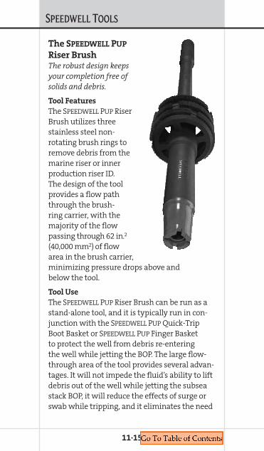
SPEEDWELL TOOLS
11·15
The SPEEDWELL PUP
Riser BrushThe robust design keepsyour completion free ofsolids and debris.
Tool Features
The SPEEDWELL PUP RiserBrush utilizes threestainless steel non-rotating brush rings toremove debris from themarine riser or innerproduction riser ID.The design of the toolprovides a flow paththrough the brush-ring carrier, with themajority of the flowpassing through 62 in.2
(40,000 mm2) of flowarea in the brush carrier,minimizing pressure drops above andbelow the tool.
Tool Use
The SPEEDWELL PUP Riser Brush can be run as astand-alone tool, and it is typically run in con-junction with the SPEEDWELL PUP Quick-TripBoot Basket or SPEEDWELL PUP Finger Basketto protect the well from debris re-enteringthe well while jetting the BOP. The large flow-through area of the tool provides several advan-tages. It will not impede the fluid’s ability to liftdebris out of the well while jetting the subseastack BOP, it will reduce the effects of surge orswab while tripping, and it eliminates the need
SPEEDWELL TOOLS
for a junk basket above the tool. The workstringcan be rotated and reciprocated with theSPEEDWELL PUP Riser Brush in the string. Thenon-rotating brush carriers reduce the risk ofdamaging the riser.
Tool Benefits
• Easier, safer handling with the integral pupjoint to facilitate tool pickup with standarddrill pipe elevators and slips: no drill collar-type clamp required
• Aggressive, non-rotating stainless steelbrushes (synthetic brushes available)
• Debris can be effectively circulated throughand around the housing
• The large mandrel ID enhances reversecirculation
• Available in 133⁄8- through 24-in. (339.7-through 609.6-mm) OD
• Large flow-through area reduces the prob-ability of fluid compression while trippingin the hole or pulling out of the hole
• The robust, non-rotating design allows thetool to be used while drilling cement
11·16
Chapter 12INTERVENTION FLUID SYSTEMS
COMPLETION FLUIDSMANUAL
12. INTERVENTIONFLUID
SYSTEMS

INTERVENTION FLUID SYSTEMS
12·1
FLODENSE APDescriptionOwing to its submicron-sized particles, theunique WARP* FLODENSE* AP system allows forflow through the annulus with minimum dis-persion and exhibits reduced sag and settle-ment. FLODENSE AP particles have a settling rate10,000 times less than barite. The fluid can beformulated for different applications with aver-age densities between 17.5 lb/gal (2.1 SG) up to20.5 lb/gal (2.46 SG).
FLODENSE AP also can be used as a viscous,lubricious and solids-free fluid that is engi-neered to fall through the annulus withminimal dispersion.
ApplicationsFLODENSE AP fluids are ideal for operationsrequiring a fluid to pass through very narrowapertures with minimum dispersion and arebeneficial in combating uncontrolled releaseof pressure from a sealed casing string.
Features• Engineered with either micron-sized particles
or solids-free• Fluid passes in snakelike fashion through
very narrow apertures• Can be formulated with densities up to
20.5 lb/gal (2.46 SG) • Can be used as a viscous, lubricious and
solids-free fluid system• Flexible system
Benefits• Reduces or controls annular pressures• Provides hydrostatic control

INTERVENTION FLUID SYSTEMS
12·2
• Produces minimum dispersion when fallingthrough the annulus
• Can be used in very narrow apertures whenengineered with micron-sized particles
• Reduces sag and settlement compared tocompeting systems
• Addresses the critical safety, environmentaland economic consequences of SustainedCasing Pressure (SCP)
FLOPRO CTDescriptionFLOPRO CT is a specialized intervention-fluidsystem featuring hydraulically optimized rheol-ogy, lubrication and density. With its relativelyflexible formulation FLOPRO CT can be built witha wide variety of base fluids, including fresh-water, seawater, potassium chloride, sodiumchloride, calcium chloride, sodium bromide,sodium formate, potassium formate andcesium formate. FLO-VIS L, a premium-gradeclarified xanthan gum, is responsible for theelevated Low-Shear-Rate-Viscosity (LSRV) of thesystem. This high-yielding biopolymer is also dis-persible and imparts the LSRV without adverselyaffecting the overall gross viscosity of the system.
ApplicationsFLOPRO CT is ideal for a wide range of coiled-tubing applications, including deeper wellswith higher angles and working in corkscrewedtubing. The solids-free FLOPRO CT system is idealfor removing debris from the wellbore andclearing the way for the insertion of productiontools. With FLOPRO CT, the hole typically can becleaned thoroughly in one trip.

INTERVENTION FLUID SYSTEMS
Features• Shear thinning rheological profile
with high LSRV • Low coefficient of friction • Zero or minimal solids• Inhibitive fluid • Provides drag reduction • Wide density range
Benefits• Reduces mechanical friction and coil wear• Promotes hole cleaning and solids suspension • Minimizes pressure loss and coil wear • Minimal reservoir damage • Enables entering higher-angle deeper wells
not previously attainable • Simplified cleanup
SAFETHERM
DescriptionThe SAFETHERM* insulating packer fluid iscustom-designed and blended for a wide rangeof cold-temperature production applications. Anaqueous, water-miscible, or oil-soluble fluid isdesigned to minimize the conduction of heataway from the production string, while sup-pressing convective heat loss in the annulus. Thisuniquely engineered packer fluid dramaticallyreduces the risks associated with the formationof hydrates, paraffin, asphaltene and the myriadof other problems that can jeopardize productionin these environments. The fluids are formulatedfrom an inherently low-thermal-conductivitybase fluid and contain no suspended solids.SAFETHERM fluids can be formulated for densities
12·3
INTERVENTION FLUID SYSTEMS
ranging from 8.33 to 12.5 lb/gal (1 to 1.5 SG) andis inhibitive to corrosion.
SAFETHERM is hydraulically optimized toyield low plastic viscosity with elevated LSRVand yield stress. Its flat rheological profile iswhat enables it to remain thermally stablefrom 125° to 175° F (52° to 79° C) over extendedperiods and is inhibitive to corrosion. Thishydraulically efficient fluid can be mixed andpumped on the rig, eliminating the expenseassociated with an adjoining pumping boat.It can be pumped at high rates through smalltubing and orifice valves. In addition, thecomponents of SAFETHERM were particularlyselected to have minimal environmentalimpact, thereby mitigating the effects of spillsor other unforeseen events.
The proprietary TPRO ST* computer modelcomplements SAFETHERM and the M-I SWACOin-house thermal conductivity testing appa-ratus. The unique computer model is capableof simulating Newtonian and non-Newtonianfluid behavior in an annulus to calculate temper-ature regression during production and shut-in.
ApplicationsSAFETHERM is specially engineered for deep-water, permafrost and other cold-temperatureenvironments. As an insulating annular fluid,SAFETHERM is compatible with a wide rangeof fluids, elastomers and other components.
Features• Minimizes heat conduction, convective
heat loss • Easily mixed and pumped on the rig• Environmentally acceptable components
12·4

INTERVENTION FLUID SYSTEMS
• Utilizes proprietary heat-transfercomputer model
• Thermally stable• pH buffered and corrosion inhibitive
Benefits• Prevents production-line blockage,
casing-string collapse• Compatible with wide range of elastomers
and fluids • Production compatible with available surface
processing equipment• Calculates heat regression during production
and shut-in• Helps maximize production• Reduces costs
12·5

Chapter 13RESERVOIR DRILL-IN FLUIDS
COMPLETION FLUIDSMANUAL
13. RESERVOIRD
RILL-INFLUIDS
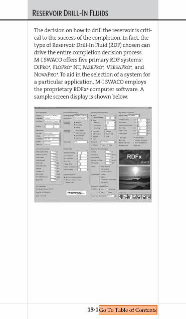
RESERVOIR DRILL-IN FLUIDS
13·1
The decision on how to drill the reservoir is criti-cal to the success of the completion. In fact, thetype of Reservoir Drill-In Fluid (RDF) chosen candrive the entire completion decision process.M-I SWACO offers five primary RDF systems:DIPRO*, FLOPRO* NT, FAZEPRO*, VERSAPRO*, andNOVAPRO*. To aid in the selection of a system fora particular application, M-I SWACO employsthe proprietary RDFx* computer software. Asample screen display is shown below.
RESERVOIR DRILL-IN FLUIDS
M-I SWACO RDF SYSTEMSDIPRO
DIPRO is a high-density water-base ReservoirDrill-In Fluid (RDF) system, designed for usein divalent brines. DIPRO utilizes a synergisticinteraction of components to produce excellentsuspension characteristics while maintainingextremely low, high-shear-rate viscosities.Optimized bridging particle selection andbiopolymer-free formulations provide a remov-able, ultra-low permeability filter cake. An idealcandidate for production-zone drilling inhighly deviated and horizontal wells, DIPRO
typically is easy to mix at the rigsite or mudplant without specialized shearing equipment.A temperature of 105° F (41° C) is the minimumtemperature required starting a mix. DIPRO
can be used in high-density divalent brines, i.e.,CaBr2, CaCl2, ZnBr2/CaBr2, MgCl2, MgBr2, andwhere bottomhole pressures require 11.5 to17.5 lb/gal (1.38 to 2.1 SG) densities.
Features
• Stable rheologies • Formulated from multi-functional
synergistic components • Can be formulated from more economic
mixed-salt base brines• Consistently low fluid loss• No pre-hydration of polymer required• Extremely low, high-shear-rate viscosities
Benefits
• Non-damaging reservoir drill-in fluidcapability in >13.5 lb/gal (1.62 SG) range
• Excellent drilling properties • Minimized formation damage potential
13·2
RESERVOIR DRILL-IN FLUIDS
• Reduced Equivalent Circulating Densities (ECD)• Designed for maximum compatibility with
completion method• Enhanced filter-cake removal• Precisely controlled particle size
13·3
Product Concentration
Divalent base brine ~ 0.96 bbl
DI-TROL* 6.0 – 10.0 lb/bbl
DI-BALANCE* 0.50 – 2.0 lb/bbl
SAFE-CARB* 2 3.0 lb/bbl
SAFE-CARB* 10, 20, 40 and/or 250 22.0 – 35.0 lb/bbl
Typical Formulation

RESERVOIR DRILL-IN FLUIDS
13·4
Pro
du
ctF
un
ctio
ns
De
scri
pti
on
CaC
l 2, C
aBr 2
, CaC
l 2/C
aBr 2
CaB
r 2/Z
nB
r 2C
aCl 2
/CaB
r 2/Z
nB
r 2D
ensi
ty a
nd
sh
ale
inh
ibit
ion
Bas
e br
ine
DI-
TRO
LFl
uid
-los
s co
ntr
ol, v
isco
sity
Star
ch d
eriv
ativ
e
DI-
BALA
NC
Ep
H c
ontr
ol, v
isco
sity
Inor
gan
ic c
omp
oun
d
SAFE
-CA
RB
2, 1
0, 2
0, 4
0 an
d/o
r 25
0Po
re-t
hro
at b
rid
gin
gO
pti
mal
ly s
ized
cal
ciu
m c
arbo
nat
e
DI-
BO
OST
* (o
pti
onal
)V
isco
sity
sta
bili
zati
onG
lyco
l ble
nd
Pro
du
ct F
un
ctio
ns
an
d D
esc
rip
tio
ns
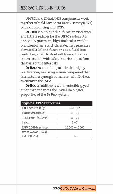
RESERVOIR DRILL-IN FLUIDS
DI-TROL and DI-BALANCE components worktogether to build Low-Shear-Rate Viscosity (LSRV)without producing high ECDs.
DI-TROL is a unique dual-function viscosifierand filtrate reducer for the DIPRO system. It isa specially processed, high-molecular-weight,branched-chain starch derivate, that generateselevated LSRV and functions as a fluid-loss-control agent in divalent salt brines. It worksin conjunction with calcium carbonate to formthe basis of the filter cake.
DI-BALANCE is a fine-particle-size, highlyreactive inorganic magnesium compound thatinteracts in a synergistic manner with DI-TROL
to enhance the LSRV.DI-BOOST additive is water-miscible glycol
ether that enhances the initial rheologicalproperties of the DI-PRO system.
13·5
Fluid density, lb/gal 11.6 – 17
Plastic viscosity, cP 15 – 35
Yield point, lb/100 ft2 15 – 35
3 rpm 2 – 7
LSRV 0.0636 sec–1, cps 10,000 – 40,000
HTHP, mL/60 min @ 150° F (66° C) <5
Typical DIPRO Properties
RESERVOIR DRILL-IN FLUIDS
FAZEPRO
FAZEPRO* is unique, in that it is the industry’sonly invert-emulsion fluid that can be convertedfrom an oil-wet state to a water-wet statethrough a simple reduction in pH. By simplyadjusting the pH of either the breaker solutionor the completion brine, the wettability of thefilter cake is transformed from an oil-wet stateto water wet. FAZEPRO can use any type of baseoil (diesel, mineral oil and synthetic) normallyused in invert-emulsion RDF systems.
Features
• Oil-base mud drilling performance• Cleans up like water-base mud• Versatility in selection of base fluid
Benefits
• Exhibits invert-emulsion fluids drillingperformance
• Can be built using diesel, mineral oil orsynthetic-base fluid
• Easily converted from an oil-continuous phase(oil-wet) to a water-continuous phase (water-wet) by using acid to reduce the pH to below 7
• Deposited filter cake can be removed usingtypical oilfield acids, i.e., citric, acetic, HCl, etc.
• Compatible with gravel-packing operationswhere a breaker can be placed in the gravel-pack carrier fluid
FAZEPRO is a reversible, invert-emulsion sys-tem. The residual filter cake is reversed from anoil-wet state to a water-wet state by creating alow-pH (<6) environment in the wellbore. Thiscan be done with acids or chelants. In addition,the internal phase can be made with differentbrines to provide the required density withminimal solids.
13·6

RESERVOIR DRILL-IN FLUIDS
13·7
Product Concentration
Base fluid (diesel synthetic, mineral oil, olefin, paraffin) 0.517 bbl
CaCl2, CaBr2, NaCl, NaBr 0.368 bbl
VG-69*, VG-PLUS* 1.0 – 5.0 lb/bbl
FAZE-MUL* 8.0 – 12.0 lb/bbl
FAZE-WET* 1.0 – 4.0 lb/bbl
Lime 5.0 – 9.0 lb/bbl
ECOTROL* for high HT applications 0.5 – 1.5 lb/bbl
SAFE-CARB 2, 10, 20, 40 and/or 250 60.0 lb/bbl
Typical Formulation
Product Functions
Base fluid (synthetic, Provides continuous phase mineral oil, olefin, paraffin) for system
CaCl2, CaBr2, NaCl, NaBr Internal phase inhibition
VG-69, VG-PLUS Viscosity
FAZE-MUL Primary emulsifier
FAZE-WET Wetting agent/HTHPfluid-loss-control agent
Lime Alkalinity
ECOTROL Fluid-loss control for temperature >250° F (125° C)
SAFE-CARB 2, 10, 20, 40 Acid-soluble and/or 250 bridging material
Product Functions
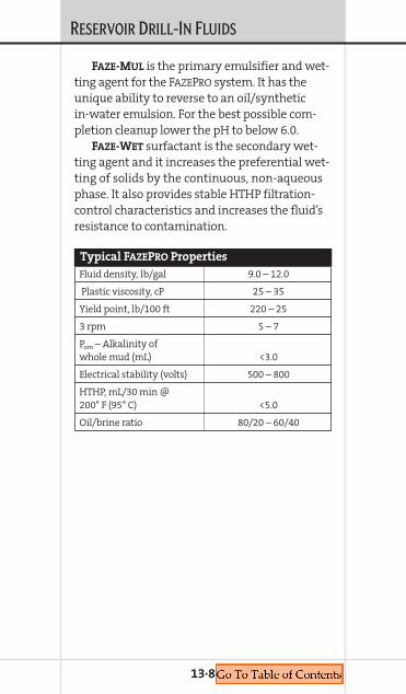
RESERVOIR DRILL-IN FLUIDS
FAZE-MUL is the primary emulsifier and wet-ting agent for the FAZEPRO system. It has theunique ability to reverse to an oil/syntheticin-water emulsion. For the best possible com-pletion cleanup lower the pH to below 6.0.
FAZE-WET surfactant is the secondary wet-ting agent and it increases the preferential wet-ting of solids by the continuous, non-aqueousphase. It also provides stable HTHP filtration-control characteristics and increases the fluid’sresistance to contamination.
13·8
Fluid density, lb/gal 9.0 – 12.0
Plastic viscosity, cP 25 – 35
Yield point, lb/100 ft 220 – 25
3 rpm 5 – 7
Pom – Alkalinity of whole mud (mL) <3.0
Electrical stability (volts) 500 – 800
HTHP, mL/30 min @ 200° F (95° C) <5.0
Oil/brine ratio 80/20 – 60/40
Typical FAZEPRO Properties

RESERVOIR DRILL-IN FLUIDS
FLOPRO NTFLOPRO* NT is used primarily for open-hole com-pletions including sand control and non-sandcontrol requirements. The main focus is to min-imize formation damage, completion compati-bility and cleanup. FLOPRO NT is purpose-builtfor each specific application.
Features
• Non-damaging• Low lift-off• High return permeability• Ultra-Low permeability filter cake• Customized formulations• Precisely controlled particle-size distribution
of bridging agent• Extremely low coefficient of friction • Promotes low skin values• Rheologically engineered• High LSRV• Environmentally acceptable
Benefits
• Maximizes production• Reduces remediation costs• Higher production rates sooner• Minimal lift-off required, faster cleanup• Minimizes solids and fluid invasion of the
producing formation • Reduces pump pressures• Maximizes ROP, saves drilling time• Excellent hole-cleaning profile• Reduces cleanup and disposal costs• Works with any completion assembly
13·9

RESERVOIR DRILL-IN FLUIDS
FLOPRO NT is the premier M-I SWACO water-base Reservoir Drill-In Fluid (RDF) system. Itis a comprehensive system that begins todemonstrate its benefits while drilling theproductive interval. These benefits continuethroughout the process of putting the wellon production.
The system is used primarily for open-holecompletions including sand control and non-sand control requirements. The main focus isto minimize formation damage, completioncompatibility, maximum drillability andcleanup. The differences between this systemand other water-base RDF systems include:product positioning, the utilization of “NewTechnologies” and component flexibility.FLOPRO NT is purpose-built for each specificdrilling and completion application.
13·10
Product Concentration
Base fluid (brine) — halide or formates 0.96 bbl
FLO-VIS* PLUS, FLO-VIS NT 0.75 – 2.0 lb/bbl
DUAL-FLO*, FLO-TROL* 4.0 – 8.0 lb/bbl
Greencide 25G 0.5 – 1.0 gal/100 bbl
Caustic Soda, MgO, KOH 0.5 – 1.0 lb/bbl
SAFE-CARB 2, 10, 20, 40 and/or 250 25.0 – 30.0 lb/bbl
KLA-GARD*, KLA-STOP* 4.0 – 8.0 lb/bbl
Typical Formulation

RESERVOIR DRILL-IN FLUIDS
13·11
Pro
du
ctF
un
ctio
ns
De
scri
pti
on
Bas
e fl
uid
(bri
ne)
Den
sity
an
d s
hal
e in
hib
itio
n
Bas
e br
ine
FLO
-VIS
PLU
S, F
LO-V
ISN
TV
isco
sity
pro
per
ties
, esp
ecia
lly L
SRV
Prem
ium
gra
de
xan
than
gu
m
DU
AL-
FLO
, FLO
-TR
OL
Flu
id-l
oss
con
trol
Mod
ifie
d s
tarc
h
Gre
enci
de
25G
Bac
teri
cid
eG
luta
rald
ehyd
e
Cau
stic
Sod
a, M
gO, K
OH
pH
Alk
alin
ity
SAFE
-CA
RB
2, 1
0, 2
0, 4
0 an
d/o
r 25
0B
rid
gin
g ag
ent,
flu
id-l
oss
Op
tim
ally
siz
ed c
alci
um
car
bon
ate
con
trol
, den
sity
KLA
-GA
RD
, KLA
-STO
PSh
ale
inh
ibit
orA
min
e ty
pe
of s
hal
e in
hib
itor
s
Pro
du
ct F
un
ctio
ns
an
d D
esc
rip
tio
ns
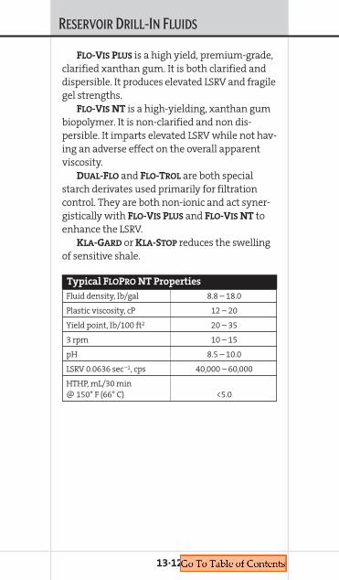
RESERVOIR DRILL-IN FLUIDS
FLO-VIS PLUS is a high yield, premium-grade,clarified xanthan gum. It is both clarified anddispersible. It produces elevated LSRV and fragilegel strengths.
FLO-VIS NT is a high-yielding, xanthan gumbiopolymer. It is non-clarified and non dis-persible. It imparts elevated LSRV while not hav-ing an adverse effect on the overall apparentviscosity.
DUAL-FLO and FLO-TROL are both specialstarch derivates used primarily for filtrationcontrol. They are both non-ionic and act syner-gistically with FLO-VIS PLUS and FLO-VIS NT toenhance the LSRV.
KLA-GARD or KLA-STOP reduces the swellingof sensitive shale.
13·12
Fluid density, lb/gal 8.8 – 18.0
Plastic viscosity, cP 12 – 20
Yield point, lb/100 ft2 20 – 35
3 rpm 10 – 15
pH 8.5 – 10.0
LSRV 0.0636 sec–1, cps 40,000 – 60,000
HTHP, mL/30 min @ 150° F (66° C) <5.0
Typical FLOPRO NT Properties

RESERVOIR DRILL-IN FLUIDS
VERSAPRO, NOVAPRO and PARAPRO
NOVAPRO (synthetic), VERSAPRO (diesel or mineraloil) and PARAPRO (paraffin) Reservoir Drill-InFluid (RDF) systems are non-damaging, invert-emulsion fluids used for drilling developmen-tal wells designed for both cased and openhole completions. These RDFs are designedto minimize formation damage problemssuch as oil wetting, emulsion blocking, andsolids plugging, yet retain OBM/SBM advan-tages — such as rate of penetration, lubricityand wellbore stability.
Due to the higher priority of minimizing for-mation damage and compatibility with com-pletion assemblies, these fluids are differentfrom typical invert-emulsion fluids in theirdesign and application. The emulsifier/wettingagent package, the type and size of bridgingmaterial — indeed, all materials required forthe job — are reviewed for the best combina-tion of drilling and completion characteristics.The NOVAPRO/VERSAPRO/PARAPRO family of flu-ids is versatile, providing tremendous flexibilityfor numerous applications.
VERSAPRO
The invert-emulsion-base VERSAPRO* reservoirdrill-in fluid system features low fluid loss,high ROP and excellent wellbore stability. TheVERSAPRO system is designed to minimize for-mation damage by forming a thin, durable,Ultra-Low-permeability filter cake on the face ofthe formation, thereby minimizing fluid andsolids invasion into the formation. Products arecarefully selected for compatibility with thereservoir and completion method to maximize
13·13
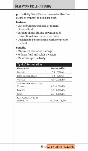
RESERVOIR DRILL-IN FLUIDS
productivity. VERSAPRO can be used with eitherdiesel, or mineral oil as a base fluid.
Features
• Can be built using diesel, or mineral oil-base fluid
• Exhibits all the drilling advantages ofconventional invert-emulsion fluids
• Designed to be compatible with completionmethod
Benefits
• Minimizes formation damage• Reduces fluid and solids invasion• Maximizes productivity
13·14
Component Concentration
Base oil 50 – 70% vol
Brine internal phase 30 – 50% vol
VG-PLUS 0.5 – 2.0 lb/bbl
VERSAPRO P/S, VERSACOAT*, VERSAWET* 4.0 – 6.0 lb/bbl
ECOTROL 1.0 – 2.5 lb/bbl
Lime 2.0 – 6.0 lb/bbl
SAFE-CARB 2, 10, 20, 40 and/or 250 10.0 – 30.0 lb/bbl
Typical Formulation

RESERVOIR DRILL-IN FLUIDS
VERSAPRO systems are non-damaging,invert-emulsion fluids with (diesel or mineraloil as base). These systems are designed tominimize formation damage.
VERSAPRO LS provides all the benefits of aVERSAPRO system. It utilizes calcium carbonatefor bridging and weighting. It contains at least30 lb/bbl (13.6 kg/bbl) for optimum bridging.
VERSAPRO SF is a pill designed without solidsto displace VERSAPRO from the hole when thereis pre-existing filter cake only. Do not useVERSAPRO SF to drill the formation.
13·15
Product Function
Base oil Continuous
Brine Internal phase
VG-PLUS Viscosifier
VERSAPRO P/S, VERSACOAT, Primary emulsifierVERSAWET
ECOTROL Supplemental fluid-loss control
Lime Alkalinity
SAFE-CARB 2,10,20,40, Acid-solubleand/or 250 bridging material
Product Functions
Fluid density, lb/gal 9.0 – 16.0
Plastic viscosity, cP 10 – 40
Yield point, lb/100 ft2 10 – 25
3 rpm 5 – 15
Pom – Alkalinity of whole mud (mL) <3.0
Electrical stability (volts) >300
HTHP, mL/30 min @ 250° F(121° C) – 5 micron disk <5.0
Typical VERSAPRO Properties
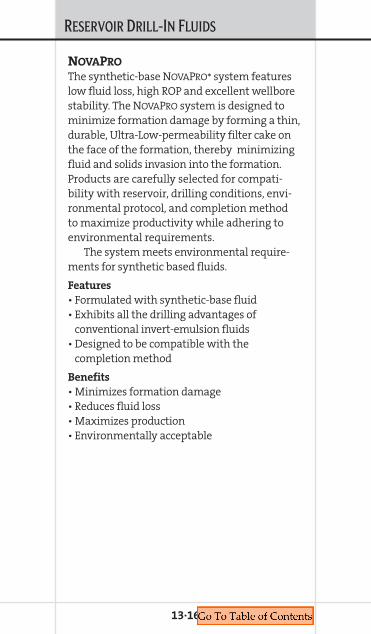
RESERVOIR DRILL-IN FLUIDS
NOVAPRO
The synthetic-base NOVAPRO* system featureslow fluid loss, high ROP and excellent wellborestability. The NOVAPRO system is designed tominimize formation damage by forming a thin,durable, Ultra-Low-permeability filter cake onthe face of the formation, thereby minimizingfluid and solids invasion into the formation.Products are carefully selected for compati-bility with reservoir, drilling conditions, envi-ronmental protocol, and completion methodto maximize productivity while adhering toenvironmental requirements.
The system meets environmental require-ments for synthetic based fluids.
Features
• Formulated with synthetic-base fluid• Exhibits all the drilling advantages of
conventional invert-emulsion fluids• Designed to be compatible with the
completion method
Benefits
• Minimizes formation damage • Reduces fluid loss• Maximizes production• Environmentally acceptable
13·16
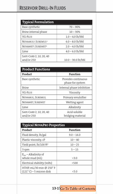
RESERVOIR DRILL-IN FLUIDS
13·17
Base synthetic 70 – 90%
Brine internal phase 10 – 30%
VG-PLUS 1.0 – 4.0 lb/bbl
NOVAMUL*, SUREMUL* 6.0 – 8.0 lb/bbl
NOVAWET*, SUREWET* 2.0 – 4.0 lb/bbl
Lime 4.0 – 6.0 lb/bbl
SAFE-CARB 2, 10, 20, 40 and/or 250 10.0 – 30.0 lb/bbl
Typical Formulation
Product Function
Base synthetic Provides continuous phase for system
Brine Internal phase inhibition
VG-PLUS Viscosity
NOVAMUL, SUREMUL Primary emulsifier
NOVAWET, SUREWET Wetting agent
Lime Alkalinity
SAFE-CARB 2, 10, 20, 40 Acid-soluble and/or 250 bridging material
Product Functions
Product Function
Fluid density, lb/gal 9.0 – 16.0
Plastic viscosity, cP 10 – 40
Yield point, lb/100 ft2 10 – 25
3 rpm 5 – 15
Pom – Alkalinity of whole mud (mL) <3.0
Electrical stability (volts) >500
HTHP, mL/30 min @ 250° F(121° C) – 5 micron disk <5.0
Typical NOVAPRO Properties
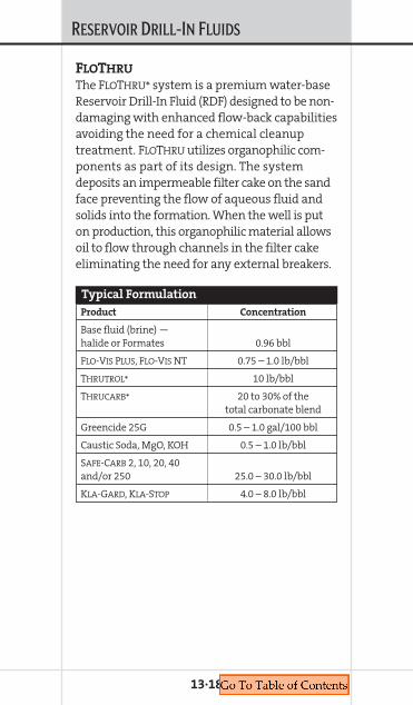
RESERVOIR DRILL-IN FLUIDS
FLOTHRU
The FLOTHRU* system is a premium water-baseReservoir Drill-In Fluid (RDF) designed to be non-damaging with enhanced flow-back capabilitiesavoiding the need for a chemical cleanuptreatment. FLOTHRU utilizes organophilic com-ponents as part of its design. The systemdeposits an impermeable filter cake on the sandface preventing the flow of aqueous fluid andsolids into the formation. When the well is puton production, this organophilic material allowsoil to flow through channels in the filter cakeeliminating the need for any external breakers.
13·18
Product Concentration
Base fluid (brine) — halide or Formates 0.96 bbl
FLO-VIS PLUS, FLO-VIS NT 0.75 – 1.0 lb/bbl
THRUTROL* 10 lb/bbl
THRUCARB* 20 to 30% of the total carbonate blend
Greencide 25G 0.5 – 1.0 gal/100 bbl
Caustic Soda, MgO, KOH 0.5 – 1.0 lb/bbl
SAFE-CARB 2, 10, 20, 40 and/or 250 25.0 – 30.0 lb/bbl
KLA-GARD, KLA-STOP 4.0 – 8.0 lb/bbl
Typical Formulation
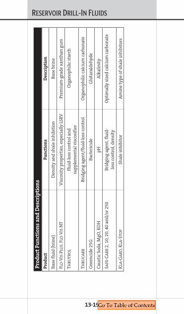
RESERVOIR DRILL-IN FLUIDS
13·19
Pro
du
ctF
un
ctio
ns
De
scri
pti
on
Bas
e fl
uid
(bri
ne)
Den
sity
an
d s
hal
e in
hib
itio
nB
ase
brin
e
FLO
-VIS
PLU
S, F
LO-V
ISN
TV
isco
sity
pro
per
ties
, esp
ecia
lly L
SRV
Prem
ium
-gra
de
xan
than
gu
m
THR
UTR
OL
Flu
id-l
oss
con
trol
an
d
Org
anop
hil
ic s
tarc
hsu
pp
lem
enta
l vis
cosi
fier
THR
UC
AR
BB
rid
gin
g ag
ent/
flu
id-l
oss
con
trol
Org
anop
hil
ic c
alci
um
car
bon
ate
Gre
enci
de
25G
Bac
teri
cid
eG
luta
rald
ehyd
e
Cau
stic
Sod
a, M
gO, K
OH
pH
Alk
alin
ity
SAFE
-CA
RB
2, 1
0, 2
0, 4
0 an
d/o
r 25
0B
rid
gin
g ag
ent,
flu
id-
Op
tim
ally
siz
ed c
alci
um
car
bon
ate
loss
con
trol
, den
sity
KLA
-GA
RD
, KLA
-STO
PSh
ale
inh
ibit
orA
min
e ty
pe
of s
hal
e in
hib
itor
s
Pro
du
ct F
un
ctio
ns
an
d D
esc
rip
tio
ns
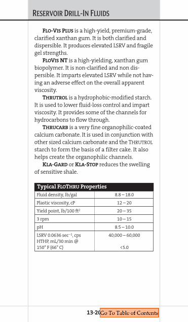
RESERVOIR DRILL-IN FLUIDS
FLO-VIS PLUS is a high-yield, premium-grade,clarified xanthan gum. It is both clarified anddispersible. It produces elevated LSRV and fragilegel strengths.
FLOVIS NT is a high-yielding, xanthan gumbiopolymer. It is non-clarified and non dis-persible. It imparts elevated LSRV while not hav-ing an adverse effect on the overall apparentviscosity.
THRUTROL is a hydrophobic-modified starch.It is used to lower fluid-loss control and impartviscosity. It provides some of the channels forhydrocarbons to flow through.
THRUCARB is a very fine organophilic-coatedcalcium carbonate. It is used in conjunction withother sized calcium carbonate and the THRUTROL
starch to form the basis of a filter cake. It alsohelps create the organophilic channels.
KLA-GARD or KLA-STOP reduces the swellingof sensitive shale.
13·20
Fluid density, lb/gal 8.8 – 18.0
Plastic viscosity, cP 12 – 20
Yield point, lb/100 ft2 20 – 35
3 rpm 10 – 15
pH 8.5 – 10.0
LSRV 0.0636 sec–1, cps 40,000 – 60,000HTHP, mL/30 min @ 150° F (66° C) <5.0
Typical FLOTHRU Properties

RESERVOIR DRILL-IN FLUIDS
13·21
Breakers – Chemical cleanupWhy a Breaker?Most of the M-I SWACO Reservoir Drill-In Fluids(RDFs) are designed to deposit an impermeablefilter cake on the formation with the intent ofpreventing the loss of fluid and solids into theproducing or injection zone. While these filtercakes provide a protective barrier on the forma-tion face in the drilling phase of the well, theycan also impair the productivity of a well or theinjection into a well if they are not cleaned upproperly.
In producing wells that are completedin unconsolidated formations, gravel packs,expandable screens, pre-packed liners andstand-alone screens are used to stabilize thewellbore. Although these completion tech-niques might stabilize the wellbore they can,at the same time, serve as potential traps forthe filter cake/filter-cake debris when thewell is put on production. The net result canbe lost production and/or premature declineof the well.
The purpose of using a breaker is to preventthe plugging of a gravel pack or a completionassembly with filter cake/filter-cake debris bycleaning up or changing the characteristics ofthe filter cake itself. Filter-cake cleanup allowshydrocarbons from the reservoir to flow freelyinto the well without being blocked by thefilter-cake residue.
The maintenance of the RDF while drillingthe well plays an important role in the cleanupprocess of the filter cake. If the percent of drillsolids in the RDF is allowed to escalate then

RESERVOIR DRILL-IN FLUIDS
consequently the amount of drill solids in thefilter cake will also accumulate. A large amountof drill solids will not only affect the integrityof the filter cake, it will also limit the amountof the filter cake that can be cleaned up.
One of the most important objectives of acleanup treatment is the uniform degradationof the filter cake. This objective should be one ofthe basis of design when selecting a breakertreatment.
Factors that affect Breaker Selection• Breaker carrier • Well type – Producer or injector• Type of completion – Gravel pack, expandable
screen, etc.• Metallurgy• Formation characteristics — Sensitivities• Environmental issues• Type of RDF used to drill the well• RDF components• % drill solids in the filter cake• MBT concentration• Amount of bridging material • Total amount of solids• Thickness of the filter cake• Type of cleanup desired• Contact area • Contact time• BHT• Delay time required• Completion equipment• Operator concerns
13·22

RESERVOIR DRILL-IN FLUIDS
13·23
What to Use, When to Use It
and How Do You Get It There?What to use and when to use it depends onthe factors affecting the breaker selectionincluding the type of cleanup desired andwhen the cleanup is going to take place. Forexample, in a gravel-pack completion there aretwo options when to do the cleanup, during thegravel-pack operation or post-gravel pack. Thereis also the option of placing a breaker as a com-ponent in the filter cake, or using a system thatdeposits a filter cake that can be cleaned up byformation hydrocarbons.
OptionsPost Treatment
• Aggressive treatmentsStrong acidsOxidizers
• Non-aggressive treatmentsWeak acidsBREAKDOWN*FAZEBREAK*BREAKFREE*
Treatments While Completing the Well
• Aggressive treatmentsChelants
• Non-aggressive treatmentsFAZEBREAK — Delayed
Chemical Options• Acids – Temperature ranges 120° to 250° F
(49° to 121° C). Attack biopolymers and cal-cium carbonate components of a water-basefilter cake. Acids can also be used to cleanup FAZEPRO, a reversible invert-emulsion fluid.

RESERVOIR DRILL-IN FLUIDS
Some of the disadvantages of acid are thatthey can cause corrosion with downhole tubu-lars, form precipitates, cause emulsions andcause incomplete cleanup. • Oxidizers – Temperature ranges 80° to 200° F
(27° to 93° C). They attack the organic polymerportion of the filter cake deposited by water-base fluids. Generally, oxidizers may worktwo times faster for every 10° F (–12° C) risein temperature.
Disadvantages of oxidizers include theattack on steel material, the dissolution of sili-cates or micro-porous chert, and the reactionwith clays which can generate an emulsion.
M-I SWACO Products• SAFE-BREAK* L – Oxidizer• Sodium Hypochlorite – Oxidizer
SAFE-BREAK L and SAFE-BREAK S are strongoxidizers used in water-base drill-in fluids asbreakers for various polymers. They are used to“break” the viscosity of natural polymer-basefluids and to loosen the filter cakes of drill-influids, so that bridging particles can be pro-duced back through sand-control liners or bemore effectively acidized.• Enzymes — Temperature ranges 40° to 200° F
(4° to 94° C). Enzymes primarily starch or poly-mer specific. These enzymes break down thepolymers in the residual filter cake which ineffect breaks down the “cement” which bondsthe filter cake together allowing the bridgingsolids to disperse and either flow back throughthe completion assembly (gravel pack), orbe chemically dissolved by other chemicaltreatments.
13·24
RESERVOIR DRILL-IN FLUIDS
M-I SWACO Products• WELLZYME* A• WELLZYME NS
Both WELLZYME A and WELLZYME NS arestarch-specific enzymes (Amylase) designed todegrade the starch component of the FLOPRO NTfilter cake. They work in monovalent carrierbrines, but do not work in divalent brines.
The optimum concentration of WELLZYME Aor WELLZYME NS is 2 to 5% volume. • Chelants — Dissolve the calcium carbonate
material in both water and reversible oil-basefluids. They are less aggressive than acids oroxidizers allowing for a more even breakdownof the filter cake and a delayed break if that isdesired. Chelants can be used in combinationwith other breakers such as enzymes or acidfor a more enhanced filter-cake cleanup. LowpH chelants are also effective in destroyingthe integrity of the FAZEPRO (reversible oil-base) filter cake.
Chelants are non-corrosive as opposedto acid.
M-I SWACO Products• D-SOLVER* pH 4.5 to 4.8• D-SOLVER PLUS pH 3.5 to 4.0
Both D-SOLVER and D-SOLVER PLUS are not
compatible with seawater or calcium chloride
or other divalent brines.
The concentration of chelants will dependon the amount of calcium carbonate material inthe filter cake, the surface area of the filter cake,and the volume of the breaker system.
13·25

RESERVOIR DRILL-IN FLUIDS
M-I SWACO Breaker Systems• BREAKFREE – Enzyme-base system• BREAKDOWN – Enzyme/chelant-base system• FAZEBREAK – Chelant-base system for FAZEPRO
BREAKFREE – Enzyme-Base SystemBREAKFREE is recommended for the cleanup ofthe starch component of a FLOPRO NT filter cakewhere stand-alone or gravel-pack open-holecompletions are used. The process of the starchdestruction is slow and gentle and it preventsformation of emulsions and precipitates withformation fluids. It also disperses bridging par-ticles to flowback or fall out of the way.• Monovalent-base brines• Dispersant – SAPP*, D-SPERSE* (optional)• WELLZYME A or WELLZYME NS• Viscosifier (optional) — Increases delay
BREAKDOWN — Enzyme/Chelant
CompositionBREAKDOWN is recommended for the cleanup ofboth the starch and calcium carbonate compo-nents of a FLOPRO NT filter cake for stand-aloneand premium screen/gravel-pack open-holecompletions. The process of the starch and cal-cium carbonate destruction is slow and gentleand it prevents formation of emulsions andprecipitates with formation fluids. • Monovalent base brines • Dispersant – SAPP, D-SPERSE (optional)• WELLZYME A or WELLZYME NS• D-SOLVER or D-SOLVER PLUS — Chelant • Viscosifier (optional) — Increases delay
13·26

RESERVOIR DRILL-IN FLUIDS
FAZEBREAK
FAZEBREAK is designed to clean up FAZEPRO.It does not completely dissolve the filter cake;it disperses the filter cake. The low pH of thesystem helps initiate the reversibility of thefilter cake and the chelant attacks the calciumcarbonate material.• Surfactant — Water-wet carbonate (FAZE-MUL*) • Viscosifier — Delays the reversal process
(SAFE-VIS) • Dispersant — Minimizes surface interactions
(EGMBE)• Base brine — Density enables good placement• Chelant — D-SOLVER
13·27
Chapter 14ENGINEERING FORMULAS AND TABLES
COMPLETION FLUIDSMANUAL
14. ENGINEERINGFORM
ULASAND
TABLES
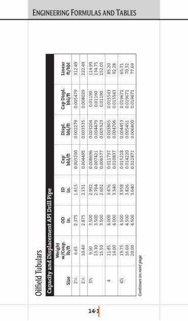
ENGINEERING FORMULAS AND TABLES
14·1
We
igh
tw
/Co
up
.O
DID
Ca
pD
isp
l.C
ap
Dis
pl.
Lin
ea
rS
ize
lb/f
tin
.in
.b
bl/
ftb
bl/
ftb
bl/
ftft
/bb
l
23 ⁄86.
652.
375
1.81
50.
0032
000.
0022
790.
0054
7931
2.49
27 ⁄810
.40
2.87
52.
151
0.00
4495
0.00
3535
0.00
8029
222.
49
3∑9.
50
3.50
0 2.
992
0.00
8696
0.
0032
04
0.01
190
114.
9913
.30
3.50
0 2.
764
0.00
7421
0.00
4479
0.
0119
0 13
4.75
15.5
0 3.
500
2.60
2 0.
0065
77
0.00
5323
0.
0119
015
2.05
4 11
.85
4.00
0 3.
476
0.01
1737
0.
0038
05
0.01
5543
85
.20
14.0
0 4.
000
3.34
0 0.
0108
37
0.00
4706
0.
0155
43
92.2
8
4∑13
.75
4.50
0 3.
958
0.01
5218
0.
0044
53
0.01
9671
65
.71
16.6
0 4.
500
3.82
6 0.
0142
20
0.00
5451
0.
0196
71
70.3
220
.00
4.50
0 3.
640
0.01
2871
0.
0068
00
0.01
9671
77
.69
Ca
pa
city
an
d D
isp
lace
me
nt
AP
I D
rill
Pip
e
Con
tin
ues
on
nex
t p
age
Oilfi
eld Tu
bular
s

ENGINEERING FORMULAS AND TABLES
14·2
We
igh
tw
/Co
up
.O
DID
Ca
pD
isp
l.C
ap
Dis
pl.
Lin
ea
rS
ize
lb/f
tin
.in
.b
bl/
ftb
bl/
ftb
bl/
ftft
/bb
l
5 16
.25
5.00
0 4.
408
0.01
8875
0.
0054
10
0.02
4286
52
.98
19.5
0 5.
000
4.27
6 0.
0177
62
0.00
6524
0.
0242
86
56.3
025
.60
5.00
0 4.
000
0.01
5543
0.
0087
43
0.02
4286
64
.34
5∑21
.90
5.50
0 4.
778
0.02
2177
0.
0072
09
0.02
9386
45
.09
24.7
0 5.
500
4.67
0 0.
0211
86
0.00
8200
0.
0293
86
47.2
0
Con
tin
ued
from
pre
viou
s p
age
Ca
pa
city
an
d D
isp
lace
me
nt
AP
I D
rill
Pip
e
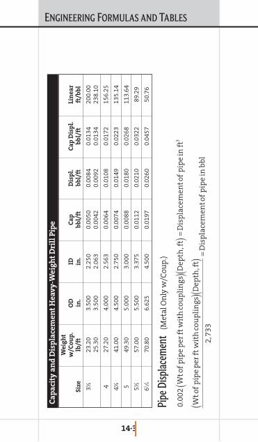
ENGINEERING FORMULAS AND TABLES
14·3
We
igh
tw
/Co
up
.O
DID
Ca
pD
isp
l.C
ap
Dis
pl.
Lin
ea
rS
ize
lb/f
tin
.in
.b
bl/
ftb
bl/
ftb
bl/
ftft
/bb
l
3∑23
.20
3.50
0 2.
250
0.00
500.
0084
0.01
34
200.
00
25.3
0 3.
500
2.06
3 0.
0042
0.00
92
0.01
34
238.
10
4 27
.20
4.00
0 2.
563
0.00
640.
0108
0.
0172
15
6.25
4∑41
.00
4.50
0 2.
750
0.00
740.
0149
0.02
23
135.
14
5 49
.30
5.00
0 3.
000
0.00
880.
0180
0.
0268
11
3.64
5∑
57.0
0 5.
500
3.37
5 0.
0112
0.
0210
0.
0322
89
.29
65 ⁄870
.80
6.62
5 4.
500
0.01
97
0.02
600.
0457
50
.76
Ca
pa
city
an
d D
isp
lace
me
nt
He
av
y-W
eig
ht
Dri
ll P
ipe
Pipe
Disp
lacem
ent
(Met
al O
nly
w/C
oup
.)
0.00
2W
tof
pip
ep
erft
wit
hco
up
lin
gs(
)Dep
th,f
t(
)=D
isp
lace
men
tof
pip
ein
ft3
Wto
fp
ipe
per
ftw
ith
cou
pli
ngs
()D
epth
,ft
()
2,73
3=
Dis
pla
cem
ento
fp
ipe
inb
bl

ENGINEERING FORMULAS AND TABLES
14·4
We
igh
tw
/Co
up
.O
DID
Ca
pD
isp
l.C
ap
Dis
pl.
Lin
ea
rS
ize
lb/f
tT
yp
ein
.in
.b
bl/
ftb
bl/
ftb
bl/
ftft
/bb
l
1 1.
14
N
1.05
0 0.
824
0.00
0660
0 0.
0004
11
0.00
1071
15
16.1
31.
20
E 1.
050
0.82
4 0.
0006
600
0.00
0411
0.00
1071
15
16.1
31.
55
U
1.05
0 0.
724
0.00
0535
0 0.
0005
36
0.00
1071
18
69.7
5
15 ⁄16
1.70
N
1.
315
1.04
9 0.
0001
069
0.00
0611
0.
0016
80
935.
491.
72
N
1.31
5 1.
049
0.00
0106
9 0.
0006
11
0.00
1680
93
5.49
1.80
I
1.31
5 1.
049
0.00
0106
9 0.
0006
11
0.00
1680
93
5.49
2.30
U
1.
315
0.95
7 0.
0089
00
0.00
0790
0.
0016
80
1124
.00
111⁄1
62.
10
I 1.
660
1.41
0 0.
0019
31
0.00
0746
0.
0026
77
517.
792.
30
N
1.66
0 1.
380
0.00
1850
0.
0008
27
0.00
2677
54
0.55
2.40
E
1.66
0 1.
380
0.00
1850
0.
0008
27
0.00
2677
54
0.55
2.33
I
1.66
0 1.
380
0.00
1850
0.
0008
27
0.00
2677
54
0.55
3.29
U
1.
660
1.26
4 0.
0015
52
0.00
1125
0.
0026
77
644.
31
Con
tin
ues
on
nex
t p
age
Ca
pa
city
an
d D
isp
lace
me
nt
AP
I T
ub
ing
an
d W
ork
stri
ng
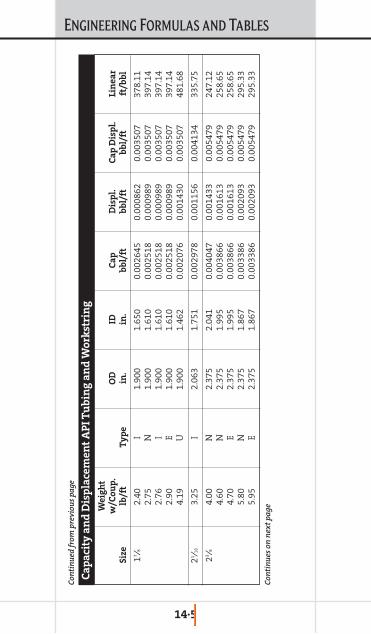
ENGINEERING FORMULAS AND TABLES
14·5
We
igh
tw
/Co
up
.O
DID
Ca
pD
isp
l.C
ap
Dis
pl.
Lin
ea
rS
ize
lb/f
tT
yp
ein
.in
.b
bl/
ftb
bl/
ftb
bl/
ftft
/bb
l
17 ⁄82.
40
I 1.
900
1.65
0 0.
0026
45
0.00
0862
0.
0035
07
378.
112.
75
N
1.90
0 1.
610
0.00
2518
0.
0009
89
0.00
3507
39
7.14
2.76
I
1.90
0 1.
610
0.00
2518
0.
0009
89
0.00
3507
39
7.14
2.90
E
1.90
0 1.
610
0.00
2518
0.
0009
89
0.00
3507
39
7.14
4.19
U
1.
900
1.46
2 0.
0020
76
0.00
1430
0.
0035
07
481.
68
21 ⁄16
3.25
I
2.06
3 1.
751
0.00
2978
0.
0011
56
0.00
4134
33
5.75
23 ⁄84.
00
N
2.37
5 2.
041
0.00
4047
0.
0014
33
0.00
5479
24
7.12
4.60
N
2.
375
1.99
5 0.
0038
66
0.00
1613
0.
0054
79
258.
654.
70
E 2.
375
1.99
5 0.
0038
66
0.00
1613
0.
0054
79
258.
655.
80
N
2.37
5 1.
867
0.00
3386
0.
0020
93
0.00
5479
29
5.33
5.95
E
2.37
5 1.
867
0.00
3386
0.
0020
93
0.00
5479
29
5.33
Con
tin
ues
on
nex
t p
age
Con
tin
ued
from
pre
viou
s p
age
Ca
pa
city
an
d D
isp
lace
me
nt
AP
I T
ub
ing
an
d W
ork
stri
ng
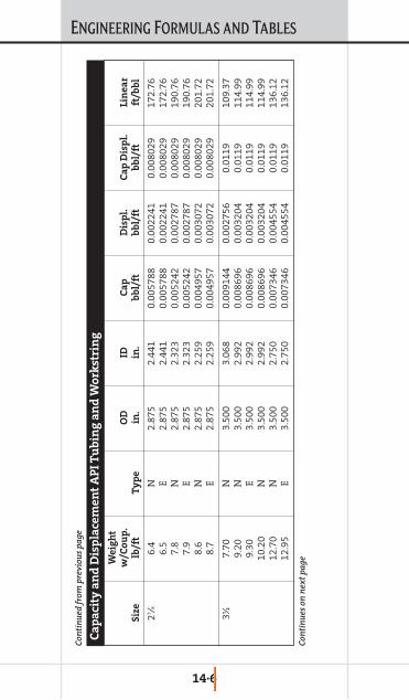
ENGINEERING FORMULAS AND TABLES
14·6
We
igh
tw
/Co
up
.O
DID
Ca
pD
isp
l.C
ap
Dis
pl.
Lin
ea
rS
ize
lb/f
tT
yp
ein
.in
.b
bl/
ftb
bl/
ftb
bl/
ftft
/bb
l
27 ⁄86.
4 N
2.
875
2.44
1 0.
0057
88
0.00
2241
0.
0080
29
172.
766.
5 E
2.87
5 2.
441
0.00
5788
0.
0022
41
0.00
8029
17
2.76
7.8
N
2.87
5 2.
323
0.00
5242
0.
0027
87
0.00
8029
19
0.76
7.9
E 2.
875
2.32
3 0.
0052
42
0.00
2787
0.
0080
29
190.
768.
6 N
2.
875
2.25
9 0.
0049
57
0.00
3072
0.
0080
29
201.
728.
7 E
2.87
5 2.
259
0.00
4957
0.
0030
72
0.00
8029
20
1.72
3∑7.
70
N
3.50
0 3.
068
0.00
9144
0.
0027
56
0.01
19
109.
379.
20
N
3.50
0 2.
992
0.00
8696
0.
0032
04
0.01
19
114.
999.
30
E 3.
500
2.99
2 0.
0086
96
0.00
3204
0.
0119
11
4.99
10.2
0 N
3.
500
2.99
2 0.
0086
96
0.00
3204
0.
0119
11
4.99
12.7
0 N
3.
500
2.75
0 0.
0073
46
0.00
4554
0.
0119
13
6.12
12.9
5 E
3.50
0 2.
750
0.00
7346
0.
0045
54
0.01
19
136.
12
Con
tin
ued
from
pre
viou
s p
age
Con
tin
ues
on
nex
t p
age
Ca
pa
city
an
d D
isp
lace
me
nt
AP
I T
ub
ing
an
d W
ork
stri
ng

ENGINEERING FORMULAS AND TABLES
14·7
We
igh
tw
/Co
up
.O
DID
Ca
pD
isp
l.C
ap
Dis
pl.
Lin
ea
rS
ize
lb/f
tT
yp
ein
.in
.b
bl/
ftb
bl/
ftb
bl/
ftft
/bb
l
4 9.
50
N
4.00
0 3.
458
0.01
2229
0.
0033
14
0.01
5543
81
.78
11.0
0 E
4.00
0 3.
476
0.01
1737
0.
0038
05
0.01
5543
85
.20
4∑12
.60
N
4.50
0 3.
958
0.01
5218
0.
0044
53
0.01
9671
65
.71
12.7
5 E
4.50
0 3.
958
0.01
5218
0.
0044
53
0.01
9671
65
.71
Type
: N
= N
on U
pset
I = In
tegr
al Jo
int
E =
Exte
rnal
Ups
et
Con
tin
ued
from
pre
viou
s p
age
Ca
pa
city
an
d D
isp
lace
me
nt
AP
I T
ub
ing
an
d W
ork
stri
ng

ENGINEERING FORMULAS AND TABLES
14·8
We
igh
tw
/Co
up
.O
DID
Ca
pD
isp
l.C
ap
Dis
pl.
Lin
ea
rS
ize
lb/f
tin
.in
.b
bl/
ftb
bl/
ftb
bl/
ftft
/bb
l
3∑
9.91
3.
500
2.99
2 0.
0086
960
0.00
3204
0.
0119
00
114.
99
4 11
.34
4.00
0 3.
428
0.01
1415
0.
0041
27
0.01
5543
87
.60
4∑9.
50
4.50
0 4.
090
0.01
6250
0.
0034
21
0.01
9671
61
.54
10.5
0 4.
500
4.05
2 0.
0159
50
0.00
3722
0.
0196
71
62.7
011
.60
4.50
0 4.
000
0.01
5543
0.
0041
29
0.01
9671
64
.34
13.0
4 4.
500
3.92
0 0.
0149
27
0.00
4744
0.
0196
71
66.9
913
.50
4.50
0 3.
920
0.01
4927
0.
0047
44
0.01
9671
66
.99
5 11
.50
5.00
0 4.
560
0.02
0199
0.
0040
86
0.02
4286
49
.51
13.0
0 5.
000
4.49
4 0.
0196
19
0.00
4667
0.
0242
86
50.9
715
.00
5.00
0 4.
408
0.01
8875
0.
0054
10
0.02
4286
52
.98
17.9
3 5.
000
4.27
6 0.
0177
62
0.00
6524
0.
0242
86
56.3
018
.00
5.00
0 4.
276
0.01
7762
0.
0065
24
0.02
4286
56
.30
Ca
pa
city
an
d D
isp
lace
me
nt
Ca
sin
g a
nd
Pla
in E
nd
Lin
ers
Con
tin
ues
on
nex
t p
age

ENGINEERING FORMULAS AND TABLES
14·9
We
igh
tw
/Co
up
.O
DID
Ca
pD
isp
l.C
ap
Dis
pl.
Lin
ea
rS
ize
lb/f
tin
.in
.b
bl/
ftb
bl/
ftb
bl/
ftft
/bb
l
521
.40
5.00
0 4.
126
0.01
6537
0.
0077
48
0.02
4286
60
.47
23.2
0 5.
000
4.04
4 0.
0158
87
0.00
8399
0.
0242
86
62.9
524
.10
5.00
0 4.
000
0.01
5543
0.
0087
43
0.02
4286
64
.34
5∑14
.00
5.50
0 5.
012
0.02
4402
0.
0049
83
0.02
9386
40
.98
15.5
0 5.
500
4.95
0 0.
0238
02
0.00
5583
0.
0293
86
42.0
117
.00
5.50
0 4.
892
0.02
3248
0.
0061
38
0.02
9386
43
.01
19.8
1 5.
500
4.77
8 0.
0221
77
0.00
7209
0.
0293
86
45.0
920
.00
5.50
0 4.
778
0.02
2177
0.
0072
09
0.02
9386
45
.09
23.0
0 5.
500
4.67
0 0.
0211
86
0.00
8200
0.
0293
86
47.2
0
65 ⁄820
.00
6.62
5 6.
049
0.03
5545
0.
0070
92
0.04
2636
28
.13
24.0
0 6.
625
5.92
1 0.
0340
56
0.00
8580
0.
0426
36
29.3
627
.65
6.62
5 5.
791
0.03
2577
0.
0100
59
0.04
2636
30
.70
28.0
0 6.
625
5.79
1 0.
0325
77
0.01
0059
0.
0426
36
30.7
032
.00
6.62
5 5.
675
0.03
1285
0.
0113
51
0.04
2636
31
.96
Con
tin
ued
from
pre
viou
s p
age
Con
tin
ues
on
nex
t p
age
Ca
pa
city
an
d D
isp
lace
me
nt
Ca
sin
g a
nd
Pla
in E
nd
Lin
ers
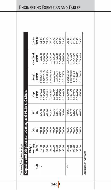
ENGINEERING FORMULAS AND TABLES
14·10
We
igh
tw
/Co
up
.O
DID
Ca
pD
isp
l.C
ap
Dis
pl.
Lin
ea
rS
ize
lb/f
tin
.in
.b
bl/
ftb
bl/
ftb
bl/
ftft
/bb
l
7 17
.00
7.00
0 6.
538
0.04
1524
0.
0060
760
0.04
7600
24
.08
20.0
0 7.
000
6.45
6 0.
0404
89
0.00
7111
00.
0476
00
24.7
023
.00
7.00
0 6.
366
0.03
9368
0.
0082
320
0.04
7600
25
.40
26.0
0 7.
000
6.27
6 0.
0382
63
0.00
9337
0 0.
0476
00
26.1
429
.00
7.00
0 6.
184
0.03
7149
0.
0104
51
0.04
7600
26
.92
32.0
0 7.
000
6.09
4 0.
0360
76
0.01
1524
0.
0476
00
27.7
235
.00
7.00
0 6.
004
0.03
5018
0.
0125
82
0.04
7600
28
.56
38.0
0 7.
000
5.92
0 0.
0340
45
0.01
3555
0.
0476
00
29.3
7
75 ⁄824
.00
7.62
5 7.
025
0.04
7940
0.
0085
390
0.05
6479
20
.86
26.4
0 7.
625
6.96
9 0.
0471
79
0.00
9300
0 0.
0564
79
21.2
029
.70
7.62
5 6.
875
0.04
5915
0.
0010
.64
0.05
6479
21
.78
33.7
0 7.
625
6.76
5 0.
0444
58
0.01
2022
0.
0564
79
22.4
939
.00
7.62
5 6.
625
0.04
2636
0.
0138
43
0.05
6479
23
.45
Con
tin
ued
from
pre
viou
s p
age
Con
tin
ues
on
nex
t p
age
Ca
pa
city
an
d D
isp
lace
me
nt
Ca
sin
g a
nd
Pla
in E
nd
Lin
ers

ENGINEERING FORMULAS AND TABLES
14·11
We
igh
tw
/Co
up
.O
DID
Ca
pD
isp
l.C
ap
Dis
pl.
Lin
ea
rS
ize
lb/f
tin
.in
.b
bl/
ftb
bl/
ftb
bl/
ftft
/bb
l
75 ⁄842
.80
7.62
5 6.
501
0.04
1055
0.
0154
24
0.05
6479
24
.36
45.3
0 7.
625
6.43
5 0.
0402
26
0.01
6253
0.
0564
79
24.8
647
.10
7.62
5 6.
375
0.03
9479
0.
0170
00
0.05
6479
25
.33
85 ⁄824
.00
8.62
5 8.
097
0.06
3688
0.
0085
77
0.07
2265
15
.70
28.0
0 8.
625
8.01
7 0.
0624
36
0.00
9829
0.
0722
65
16.0
232
.00
8.62
5 7.
921
0.06
0949
0.
0113
16
0.07
2265
16
.41
36.0
0 8.
625
7.82
5 0.
0594
81
0.01
2784
0.
0722
65
16.8
140
.00
8.62
5 7.
725
0.05
7971
0.
0142
95
0.07
2265
17
.25
49.0
0 8.
625
7.51
1 0.
0548
03
0.01
7462
0.
0722
65
18.2
5
95 ⁄832
.30
9.62
5 9.
001
0.07
8703
0.
0112
91
0.08
9994
12
.71
36.0
0 9.
625
8.92
1 0.
0773
10
0.01
2683
0.
0899
94
12.9
340
.00
9.62
5 8.
835
0.07
5827
0.
0141
67
0.08
9994
13
.19
43.5
0 9.
625
8.75
5 0.
0744
60
0.01
5534
0.
0899
94
13.4
3
Con
tin
ued
from
pre
viou
s p
age
Con
tin
ues
on
nex
t p
age
Ca
pa
city
an
d D
isp
lace
me
nt
Ca
sin
g a
nd
Pla
in E
nd
Lin
ers

ENGINEERING FORMULAS AND TABLES
14·12
We
igh
tw
/Co
up
.O
DID
Ca
pD
isp
l.C
ap
Dis
pl.
Lin
ea
rS
ize
lb/f
tin
.in
.b
bl/
ftb
bl/
ftb
bl/
ftft
/bb
l
95 ⁄847
.00
9.62
5 8.
681
0.07
3206
0.
0167
87
0.08
9994
13
.66
53.5
0 9.
625
8.53
5 0.
0707
65
0.01
9229
0.
0899
94
14.1
3
10π
32.7
5 10
.750
10
.192
0.
1009
09
0.01
1352
0.
1122
60
9.91
40.5
0 10
.750
10
.050
0.
0981
16
0.01
4144
0.
1122
60
10.1
945
.50
10.7
50
9.95
0 0.
0961
74
0.01
6087
0.
1122
60
10.4
051
.00
10.7
50
9.85
0 0.
0942
50
0.01
8010
0.
1122
60
10.6
155
.50
10.7
50
9.76
0 0.
0925
36
0.01
9725
0.
1122
60
10.8
1
11π
42.0
0 11
.750
11
.084
0.
1193
45
0.01
4773
0.
1341
18
8.38
47.0
0 11
.750
11
.000
0.
1175
43
0.01
6575
0.
1341
18
8.51
54.0
0 11
.750
10
.880
0.
1149
92
0.01
9126
0.
1341
18
8.70
60.0
0 11
.750
10
.772
0.
1127
20
0.02
1397
0.
1341
18
8.87
Con
tin
ued
from
pre
viou
s p
age
Con
tin
ues
on
nex
t p
age
Ca
pa
city
an
d D
isp
lace
me
nt
Ca
sin
g a
nd
Pla
in E
nd
Lin
ers

ENGINEERING FORMULAS AND TABLES
14·13
We
igh
tw
/Co
up
.O
DID
Ca
pD
isp
l.C
ap
Dis
pl.
Lin
ea
rS
ize
lb/f
tin
.in
.b
bl/
ftb
bl/
ftb
bl/
ftft
/bb
l
133 ⁄8
48.0
0 13
.375
12
.715
0.
1570
52
0.01
6727
0.
1737
79
6.37
54.5
0 13
.375
12
.615
0.
1545
91
0.01
9188
0.
1737
79
6.47
61.0
0 13
.375
12
.515
0.
1521
50
0.02
1629
0.
1737
79
6.57
68.0
0 13
.375
12
.415
0.
1497
28
0.02
4051
0.
1737
79
6.68
72.0
0 13
.375
12
.347
0.
1480
92
0.02
5687
0.
1737
79
6.75
16
65.0
0 16
.000
15
.250
0.
2259
17
0.02
2768
0.
2486
85
4.43
75.0
0 16
.000
15
.124
0.
2221
99
0.02
6486
0.
2486
85
4.50
84.0
0 16
.000
15
.010
0.
2188
62
0.02
9823
0.
2486
85
4.57
185 ⁄8
87.5
0 18
.625
17
.755
0.
3062
32
0.03
0746
0.
3369
79
3.27
20
94.0
0 20
.000
19
.124
0.
3552
77
0.03
3293
0.
3885
70
2.81
106.
50
20.0
00
19.0
00
0.35
0685
0.
0378
86
0.38
8570
2.
8513
3.00
20
.000
18
.730
0.
3407
89
0.04
7782
0.
3885
70
2.93
Con
tin
ued
from
pre
viou
s p
age
Ca
pa
city
an
d D
isp
lace
me
nt
Ca
sin
g a
nd
Pla
in E
nd
Lin
ers

ENGINEERING FORMULAS AND TABLES
14·14
OD
IDC
ap
Dis
pl.
Ca
p D
isp
l.L
ine
ar
Siz
ein
.in
.b
bl/
ftb
bl/
ftb
bl/
ftft
/bb
l
3∫
3.12
5 1.
2500
0.
0015
18
0.00
7969
0.
0094
87
658.
83
3∑
3.50
0 1.
5000
0.
0021
86
0.00
9714
0.
0119
00
457.
52
3π
3.75
0 1.
5000
0.
0021
86
0.01
1475
0.
0136
61
457.
52
4 4.
000
2.00
00
0.00
3886
0.
0116
57
0.01
5543
25
7.35
4∫
4.12
5 2.
0000
0.
0038
86
0.01
2644
0.
0165
29
257.
35
4∏4.
250
2.00
00
0.00
3886
0.
0136
61
0.01
7546
25
7.35
4∑
4.50
0 2.
2500
0.
0049
18
0.01
4754
0.
0196
71
203.
34
4π4.
750
2.25
00
0.00
4918
0.
0170
00
0.02
1918
20
3.34
5 5.
000
2.25
00
0.00
4918
0.
0193
68
0.02
4286
20
3.34
5∏5.
250
2.25
00
0.00
4918
0.
0218
57
0.02
6775
20
3.34
Ca
pa
city
an
d D
isp
lace
me
nt
Dri
ll C
oll
ars
Con
tin
ues
on
nex
t p
age

ENGINEERING FORMULAS AND TABLES
14·15
OD
IDC
ap
Dis
pl.
Ca
p D
isp
l.L
ine
ar
Siz
ein
.in
.b
bl/
ftb
bl/
ftb
bl/
ftft
/bb
l
Con
tin
ues
on
nex
t p
age
5∑
5.50
0 2.
2500
0.
0049
18
0.02
4468
0.
0293
86
203.
34
5π5.
750
2.25
00
0.00
4918
0.
0272
00
0.03
2118
20
3.34
6 6.
000
2.25
00
0.00
4918
0.
0300
53
0.03
4971
20
3.34
6∏6.
250
2.25
00
0.00
4918
0.
0330
28
0.03
7946
20
3.34
6.25
0 2.
8125
0.
0076
84
0.03
0262
0.
0379
46
130.
14
6∑6.
500
2.25
00
0.00
4918
0.
0361
25
0.04
1043
20
3.34
6.50
0 2.
8125
0.
0076
84
0.03
3359
0.
0410
43
130.
14
6π6.
750
2.25
00
0.00
4918
0.
0393
43
0.04
4261
20
3.34
6.75
0 2.
8125
0.
0076
84
0.03
6576
0.
0442
61
130.
14
7 7.
000
2.81
25
0.00
7684
0.
0399
16
0.04
7600
13
0.14
7∏
7.25
0 2.
8125
0.
0076
84
0.04
3376
0.
0510
61
130.
14
7∑7.
500
2.81
25
0.00
7684
0.
0469
59
0.05
4643
13
0.14
Con
tin
ued
from
pre
viou
s p
age
Ca
pa
city
an
d D
isp
lace
me
nt
Dri
ll C
oll
ars
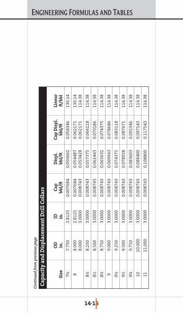
ENGINEERING FORMULAS AND TABLES
14·16
OD
IDC
ap
Dis
pl.
Ca
p D
isp
l.L
ine
ar
Siz
ein
.in
.b
bl/
ftb
bl/
ftb
bl/
ftft
/bb
l
7π7.
750
2.81
25
0.00
7684
0.
0506
62
0.05
8346
13
0.14
8 8.
000
2.81
25
0.00
7684
0.
0544
87
0.06
2171
13
0.14
8.00
0 3.
0000
0.
0087
43
0.05
3428
0.
0621
71
114.
38
8∏8.
250
3.00
00
0.00
8743
0.
0573
75
0.06
6118
11
4.38
8∑8.
500
3.00
00
0.00
8743
0.
0614
43
0.07
0186
11
4.38
8π8.
750
3.00
00
0.00
8743
0.
0656
32
0.07
4375
11
4.38
9 9.
000
3.00
00
0.00
8743
0.
0699
43
0.07
8686
11
4.38
9∏
9.25
0 3.
0000
0.
0087
43
0.07
4375
0.
0831
18
114.
38
9∑9.
500
3.00
00
0.00
8743
0.
0789
28
0.08
7671
11
4.38
9π9.
750
3.00
00
0.00
8743
0.
0836
03
0.09
2346
11
4.38
10
10.0
00
3.00
00
0.00
8743
0.
0884
00
0.09
7143
11
4.38
11
11.0
00
3.00
00
0.00
8743
0.
1088
00
0.11
7543
11
4.38
Con
tin
ued
from
pre
viou
s p
age
Ca
pa
city
an
d D
isp
lace
me
nt
Dri
ll C
oll
ars

ENGINEERING FORMULAS AND TABLES
14·17
Siz
eW
all
Ca
lc.
bb
l/L
ine
ar
ft3/
Lin
ea
rg
al/
Lin
ea
rO
DT
hic
kn
ess
wt/
ftID
Lin
ea
r ft
ft/b
bl
Lin
ea
r ft
ft/f
t3L
ine
ar
ftft
/ga
l
π0.
067
0.49
0.61
60.
0003
72,
712.
830.
0020
748
3.19
20.
0154
864
.592
5
10.
067
0.67
0.86
60.
0007
31,
372.
610.
0040
924
4.48
10.
0306
32.6
819
10.
075
0.74
0.85
0.00
071,
424.
780.
0039
425
3.77
20.
0294
833
.923
9
10.
080.
790.
840.
0006
91,
458.
900.
0038
525
9.85
0.02
879
34.7
364
10.
087
0.85
0.82
60.
0006
61,
508.
770.
0037
226
8.73
30.
0278
435
.923
9
10.
095
0.92
0.81
0.00
064
1,56
8.97
0.00
358
279.
454
0.02
677
37.3
571
10.
102
0.98
0.79
60.
0006
21,
624.
640.
0034
628
9.37
10.
0258
538
.682
7
10.
109
1.04
0.78
20.
0005
91,
683.
340.
0033
429
9.82
50.
0249
540
.080
2
10.
125
1.17
0.75
0.00
055
1,83
0.04
0.00
307
325.
956
0.02
295
43.5
733
1∏0.
067
0.85
1.11
60.
0012
182
6.52
0.00
679
147.
215
0.05
081
19.6
795
1∏0.
075
0.94
1.1
0.00
118
850.
740.
0066
151.
529
0.04
937
20.2
562
Tu
bu
lar/
Op
en
Ho
le:
Co
il T
ub
ing
Con
tin
ues
on
nex
t p
age

ENGINEERING FORMULAS AND TABLES
14·18
Siz
eW
all
Ca
lc.
bb
l/L
ine
ar
ft3/
Lin
ea
rg
al/
Lin
ea
rO
DT
hic
kn
ess
wt/
ftID
Lin
ea
r ft
ft/b
bl
Lin
ea
r ft
ft/f
t3L
ine
ar
ftft
/ga
l
1∏0.
081
1.09
0.00
115
866.
430.
0064
815
4.32
20.
0484
720
.629
6
1∏0.
087
1.08
1.07
60.
0011
288
9.12
0.00
631
158.
364
0.04
724
21.1
699
1∏0.
091.
111.
070.
0011
189
9.12
0.00
624
160.
145
0.04
671
21.4
08
1∏0.
095
1.17
1.06
0.00
109
916.
160.
0061
316
3.18
10.
0458
421
.813
8
1∏0.
097
1.19
1.05
60.
0010
892
3.12
0.00
608
164.
419
0.04
5521
.979
4
1∏0.
102
1.25
1.04
60.
0010
694
0.85
0.00
597
167.
578
0.04
464
22.4
016
1∏0.
104
1.27
1.04
20.
0010
594
8.09
0.00
592
168.
867
0.04
4322
.574
1∏0.
109
1.33
1.03
20.
0010
396
6.55
0.00
581
172.
156
0.04
345
23.0
136
1∏0.
116
1.4
1.01
80.
0010
199
3.32
0.00
565
176.
923
0.04
228
23.6
509
1∏0.
118
1.43
1.01
40.
001
1,00
1.17
0.00
561
178.
322
0.04
195
23.8
379
1∏0.
125
1.5
10.
0009
71,
029.
400.
0054
518
3.35
0.04
0824
.51
Con
tin
ues
on
nex
t p
age
Con
tin
ued
from
pre
viou
s p
age
Tu
bu
lar/
Op
en
Ho
le:
Co
il T
ub
ing

ENGINEERING FORMULAS AND TABLES
14·19
Siz
eW
all
Ca
lc.
bb
l/L
ine
ar
ft3/
Lin
ea
rg
al/
Lin
ea
rO
DT
hic
kn
ess
wt/
ftID
Lin
ea
r ft
ft/b
bl
Lin
ea
r ft
ft/f
t3L
ine
ar
ftft
/ga
l
1∏0.
134
1.6
0.98
20.
0009
41,
067.
480.
0052
619
0.13
30.
0393
425
.416
8
1∏0.
145
1.71
0.96
0.00
091,
116.
970.
0050
319
8.94
70.
0376
26.5
951
1∏0.
156
1.82
0.93
80.
0008
51,
169.
980.
0048
208.
389
0.03
5927
.857
2
1∏0.
175
2.01
0.9
0.00
079
1,27
0.86
0.00
442
226.
358
0.03
305
30.2
593
1∑0.
095
1.43
1.31
0.00
167
599.
850.
0093
610
6.84
10.
0700
214
.282
4
1∑0.
102
1.52
1.29
60.
0016
361
2.88
0.00
916
109.
162
0.06
853
14.5
926
1∑0.
109
1.62
1.28
20.
0016
626.
340.
0089
611
1.55
90.
0670
614
.913
1
1∑0.
116
1.71
1.26
80.
0015
664
0.24
0.00
877
114.
036
0.06
5615
.244
2
1∑0.
118
1.74
1.26
40.
0015
564
4.3
0.00
871
114.
759
0.06
519
15.3
408
1∑0.
125
1.84
1.25
0.00
152
658.
820.
0085
211
7.34
40.
0637
515
.686
4
1∑0.
134
1.95
1.23
20.
0014
767
8.21
0.00
828
120.
798
0.06
193
16.1
481
Con
tin
ues
on
nex
t p
age
Con
tin
ued
from
pre
viou
s p
age
Tu
bu
lar/
Op
en
Ho
le:
Co
il T
ub
ing
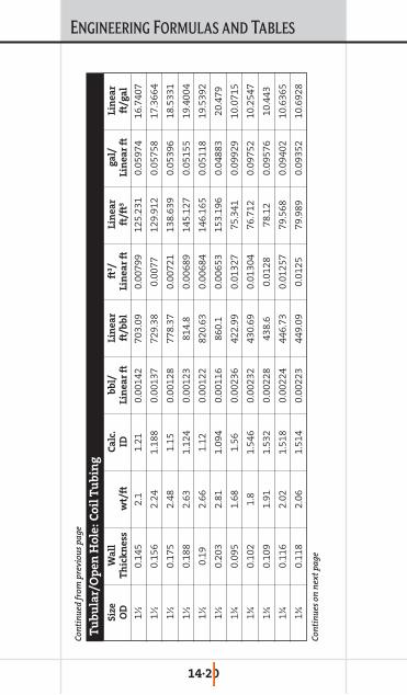
ENGINEERING FORMULAS AND TABLES
14·20
Siz
eW
all
Ca
lc.
bb
l/L
ine
ar
ft3/
Lin
ea
rg
al/
Lin
ea
rO
DT
hic
kn
ess
wt/
ftID
Lin
ea
r ft
ft/b
bl
Lin
ea
r ft
ft/f
t3L
ine
ar
ftft
/ga
l
1∑0.
145
2.1
1.21
0.00
142
703.
090.
0079
912
5.23
10.
0597
416
.740
7
1∑0.
156
2.24
1.18
80.
0013
772
9.38
0.00
7712
9.91
20.
0575
817
.366
4
1∑0.
175
2.48
1.15
0.00
128
778.
370.
0072
113
8.63
90.
0539
618
.533
1
1∑0.
188
2.63
1.12
40.
0012
381
4.8
0.00
689
145.
127
0.05
155
19.4
004
1∑0.
192.
661.
120.
0012
282
0.63
0.00
684
146.
165
0.05
118
19.5
392
1∑0.
203
2.81
1.09
40.
0011
686
0.1
0.00
653
153.
196
0.04
883
20.4
79
1π0.
095
1.68
1.56
0.00
236
422.
990.
0132
775
.341
0.09
929
10.0
715
1π0.
102
1.8
1.54
60.
0023
243
0.69
0.01
304
76.7
120.
0975
210
.254
7
1π0.
109
1.91
1.53
20.
0022
843
8.6
0.01
2878
.12
0.09
576
10.4
43
1π0.
116
2.02
1.51
80.
0022
444
6.73
0.01
257
79.5
680.
0940
210
.636
5
1π0.
118
2.06
1.51
40.
0022
344
9.09
0.01
2579
.989
0.09
352
10.6
928
Con
tin
ues
on
nex
t p
age
Con
tin
ued
from
pre
viou
s p
age
Tu
bu
lar/
Op
en
Ho
le:
Co
il T
ub
ing
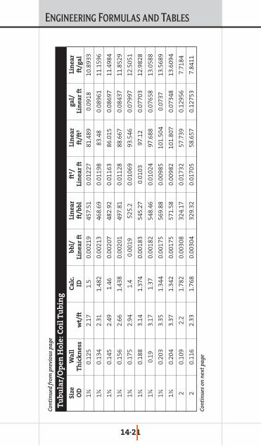
ENGINEERING FORMULAS AND TABLES
14·21
Siz
eW
all
Ca
lc.
bb
l/L
ine
ar
ft3/
Lin
ea
rg
al/
Lin
ea
rO
DT
hic
kn
ess
wt/
ftID
Lin
ea
r ft
ft/b
bl
Lin
ea
r ft
ft/f
t3L
ine
ar
ftft
/ga
l
1π0.
125
2.17
1.5
0.00
219
457.
510.
0122
781
.489
0.09
1810
.893
3
1π0.
134
2.31
1.48
20.
0021
346
8.69
0.01
198
83.4
80.
0896
111
.159
6
1π0.
145
2.49
1.46
0.00
207
482.
920.
0116
386
.015
0.08
697
11.4
984
1π0.
156
2.66
1.43
80.
0020
149
7.81
0.01
128
88.6
670.
0843
711
.852
9
1π0.
175
2.94
1.4
0.00
1952
5.2
0.01
069
93.5
460.
0799
712
.505
1
1π0.
188
3.14
1.37
40.
0018
354
5.27
0.01
0397
.12
0.07
703
12.9
828
1π0.
193.
171.
370.
0018
254
8.46
0.01
024
97.6
880.
0765
813
.058
8
1π0.
203
3.35
1.34
40.
0017
556
9.88
0.00
985
101.
504
0.07
3713
.568
9
1π0.
204
3.37
1.34
20.
0017
557
1.58
0.00
982
101.
807
0.07
348
13.6
094
20.
109
2.2
1.78
20.
0030
832
4.17
0.01
732
57.7
390.
1295
67.
7184
20.
116
2.33
1.76
80.
0030
432
9.32
0.01
705
58.6
570.
1275
37.
8411
Con
tin
ues
on
nex
t p
age
Con
tin
ued
from
pre
viou
s p
age
Tu
bu
lar/
Op
en
Ho
le:
Co
il T
ub
ing

ENGINEERING FORMULAS AND TABLES
14·22
Siz
eW
all
Ca
lc.
bb
l/L
ine
ar
ft3/
Lin
ea
rg
al/
Lin
ea
rO
DT
hic
kn
ess
wt/
ftID
Lin
ea
r ft
ft/b
bl
Lin
ea
r ft
ft/f
t3L
ine
ar
ftft
/ga
l
20.
118
2.37
1.76
40.
0030
233
0.82
0.01
697
58.9
230.
1269
67.
8767
20.
125
2.5
1.75
0.00
297
336.
130.
0167
59.8
690.
1249
58.
0033
20.
134
2.67
1.73
20.
0029
134
3.15
0.01
636
61.1
20.
1223
98.
1705
20.
145
2.87
1.71
0.00
284
352.
040.
0159
562
.703
0.11
938.
3821
20.
156
3.07
1.68
80.
0027
736
1.28
0.01
554
64.3
480.
1162
58.
602
20.
175
3.41
1.65
0.00
264
378.
110.
0148
567
.346
0.11
108
9.00
28
20.
188
3.64
1.62
40.
0025
639
0.31
0.01
438
69.5
20.
1076
9.29
33
20.
193.
671.
620.
0025
539
2.24
0.01
431
69.8
640.
1070
89.
3393
20.
203
3.9
1.59
40.
0024
740
5.14
0.01
386
72.1
610.
1036
79.
6464
20.
204
3.91
1.59
20.
0024
640
6.16
0.01
382
72.3
430.
1034
19.
6707
23 ⁄80.
109
2.64
2.15
70.
0045
222
1.25
0.02
538
39.4
080.
1898
35.
268
Con
tin
ues
on
nex
t p
age
Con
tin
ued
from
pre
viou
s p
age
Tu
bu
lar/
Op
en
Ho
le:
Co
il T
ub
ing

ENGINEERING FORMULAS AND TABLES
14·23
Siz
eW
all
Ca
lc.
bb
l/L
ine
ar
ft3/
Lin
ea
rg
al/
Lin
ea
rO
DT
hic
kn
ess
wt/
ftID
Lin
ea
r ft
ft/b
bl
Lin
ea
r ft
ft/f
t3L
ine
ar
ftft
/ga
l
23 ⁄80.
118
2.84
2.13
90.
0044
422
4.99
0.02
495
40.0
740.
1866
75.
357
23 ⁄80.
125
32.
125
0.00
439
227.
960.
0246
340
.603
0.18
424
5.42
78
23 ⁄80.
134
3.21
2.10
70.
0043
123
1.88
0.02
421
41.3
0.18
113
5.52
1
23 ⁄80.
145
3.45
2.08
50.
0042
223
6.79
0.02
371
42.1
760.
1773
75.
6381
23 ⁄80.
156
3.7
2.06
30.
0041
324
1.87
0.02
321
43.0
810.
1736
45.
759
23 ⁄80.
175
4.11
2.02
50.
0039
825
1.03
0.02
236
44.7
130.
1673
15.
9771
23 ⁄80.
188
4.39
1.99
90.
0038
825
7.61
0.02
179
45.8
830.
1630
46.
1336
23 ⁄80.
194.
431.
995
0.00
387
258.
640.
0217
146
.068
0.16
239
6.15
83
23 ⁄80.
203
4.71
1.96
90.
0037
726
5.52
0.02
114
47.2
920.
1581
86.
322
23 ⁄80.
204
4.73
1.96
70.
0037
626
6.06
0.02
1147
.388
0.15
786
6.33
48
23 ⁄80.
224
5.15
1.92
70.
0036
127
7.22
0.02
025
49.3
760.
1515
6.60
05
Con
tin
ues
on
nex
t p
age
Con
tin
ued
from
pre
viou
s p
age
Tu
bu
lar/
Op
en
Ho
le:
Co
il T
ub
ing

ENGINEERING FORMULAS AND TABLES
14·24
Siz
eW
all
Ca
lc.
bb
l/L
ine
ar
ft3/
Lin
ea
rg
al/
Lin
ea
rO
DT
hic
kn
ess
wt/
ftID
Lin
ea
r ft
ft/b
bl
Lin
ea
r ft
ft/f
t3L
ine
ar
ftft
/ga
l
25 ⁄80.
134
3.56
2.35
70.
0054
185.
30.
0303
33.0
040.
2266
64.
4119
25 ⁄80.
145
3.84
2.33
50.
0053
188.
80.
0297
433
.628
0.22
245
4.49
54
25 ⁄80.
156
4.11
2.31
30.
0052
192.
410.
0291
834
.271
0.21
828
4.58
13
25 ⁄80.
175
4.58
2.27
50.
0050
319
8.89
0.02
823
35.4
260.
2111
74.
7357
25 ⁄80.
194.
942.
245
0.00
4920
4.25
0.02
749
36.3
790.
2056
34.
8631
25 ⁄80.
204
5.27
2.21
70.
0047
720
9.44
0.02
681
37.3
030.
2005
44.
9867
25 ⁄80.
224
5.74
2.17
70.
0046
217.
20.
0258
538
.687
0.19
336
5.17
16
25 ⁄80.
256.
342.
125
0.00
439
227.
960.
0246
340
.603
0.18
424
5.42
78
25 ⁄80.
287.
012.
065
0.00
414
241.
40.
0232
642
.997
0.17
398
5.74
78
25 ⁄80.
37.
452.
025
0.00
398
251.
030.
0223
644
.713
0.16
731
5.97
71
27 ⁄80.
125
3.67
2.62
50.
0066
914
9.39
0.03
758
26.6
090.
2811
43.
557
Con
tin
ues
on
nex
t p
age
Con
tin
ued
from
pre
viou
s p
age
Tu
bu
lar/
Op
en
Ho
le:
Co
il T
ub
ing

ENGINEERING FORMULAS AND TABLES
14·25
Siz
eW
all
Ca
lc.
bb
l/L
ine
ar
ft3/
Lin
ea
rg
al/
Lin
ea
rO
DT
hic
kn
ess
wt/
ftID
Lin
ea
r ft
ft/b
bl
Lin
ea
r ft
ft/f
t3L
ine
ar
ftft
/ga
l
27 ⁄80.
134
3.92
2.60
70.
0066
151.
460.
0370
726
.977
0.27
733.
6063
27 ⁄80.
145
4.23
2.58
50.
0064
915
4.05
0.03
644
27.4
380.
2726
33.
6679
27 ⁄80.
156
4.53
2.56
30.
0063
815
6.71
0.03
583
27.9
120.
2680
13.
7312
27 ⁄80.
175
5.05
2.52
50.
0061
916
1.46
0.03
477
28.7
580.
2601
33.
8443
27 ⁄80.
188
5.4
2.49
90.
0060
716
4.84
0.03
406
29.3
590.
2548
3.92
47
27 ⁄80.
195.
452.
495
0.00
605
165.
360.
0339
529
.454
0.25
398
3.93
73
27 ⁄80.
203
5.79
2.46
90.
0059
216
8.87
0.03
325
30.0
770.
2487
24.
0207
27 ⁄80.
204
5.82
2.46
70.
0059
116
9.14
0.03
319
30.1
260.
2483
14.
0272
27 ⁄80.
224
6.34
2.42
70.
0057
217
4.76
0.03
213
31.1
270.
2403
34.
1611
27 ⁄80.
257.
012.
375
0.00
548
182.
50.
0307
632
.505
0.23
014
4.34
53
27 ⁄80.
287.
762.
315
0.00
521
192.
080.
0292
334
.212
0.21
866
4.57
34
Con
tin
ues
on
nex
t p
age
Con
tin
ued
from
pre
viou
s p
age
Tu
bu
lar/
Op
en
Ho
le:
Co
il T
ub
ing
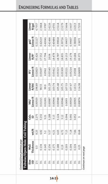
ENGINEERING FORMULAS AND TABLES
14·26
Siz
eW
all
Ca
lc.
bb
l/L
ine
ar
ft3/
Lin
ea
rg
al/
Lin
ea
rO
DT
hic
kn
ess
wt/
ftID
Lin
ea
r ft
ft/b
bl
Lin
ea
r ft
ft/f
t3L
ine
ar
ftft
/ga
l
27 ⁄80.
38.
252.
275
0.00
503
198.
890.
0282
335
.426
0.21
117
4.73
57
3∑0.
134
4.82
3.23
20.
0101
598
.55
0.05
697
17.5
520.
4261
92.
3464
3∑0.
145
5.2
3.21
0.01
001
99.9
0.05
6217
.794
0.42
041
2.37
87
3∑0.
156
5.57
3.18
80.
0098
710
1.29
0.05
543
18.0
40.
4146
62.
4116
3∑0.
175
6.21
3.15
0.00
964
103.
740.
0541
218
.478
0.40
484
2.47
01
3∑0.
188
6.65
3.12
40.
0094
810
5.48
0.05
323
18.7
870.
3981
82.
5114
3∑0.
196.
723.
120.
0094
610
5.75
0.05
309
18.8
350.
3971
62.
5179
3∑0.
203
7.15
3.09
40.
0093
107.
530.
0522
119
.153
0.39
057
2.56
04
3∑0.
204
7.18
3.09
20.
0092
910
7.67
0.05
214
19.1
780.
3900
72.
5637
3∑0.
224
7.84
3.05
20.
0090
511
0.51
0.05
0819
.684
0.38
004
2.63
13
3∑0.
258.
683
0.00
874
114.
380.
0490
920
.372
0.36
722.
7233
Con
tin
ues
on
nex
t p
age
Con
tin
ued
from
pre
viou
s p
age
Tu
bu
lar/
Op
en
Ho
le:
Co
il T
ub
ing
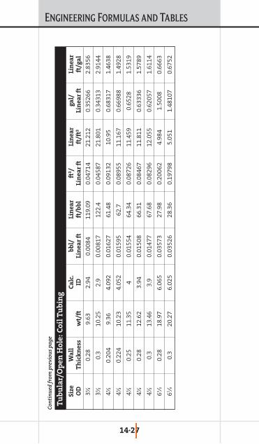
ENGINEERING FORMULAS AND TABLES
14·27
Siz
eW
all
Ca
lc.
bb
l/L
ine
ar
ft3/
Lin
ea
rg
al/
Lin
ea
rO
DT
hic
kn
ess
wt/
ftID
Lin
ea
r ft
ft/b
bl
Lin
ea
r ft
ft/f
t3L
ine
ar
ftft
/ga
l
3∑0.
289.
632.
940.
0084
119.
090.
0471
421
.212
0.35
266
2.83
56
3∑0.
310
.25
2.9
0.00
817
122.
40.
0458
721
.801
0.34
313
2.91
44
4∑0.
204
9.36
4.09
20.
0162
761
.48
0.09
132
10.9
50.
6831
71.
4638
4∑0.
224
10.2
34.
052
0.01
595
62.7
0.08
955
11.1
670.
6698
81.
4928
4∑0.
2511
.35
40.
0155
464
.34
0.08
726
11.4
590.
6528
1.53
19
4∑0.
2812
.62
3.94
0.01
508
66.3
10.
0846
711
.811
0.63
336
1.57
89
4∑0.
313
.46
3.9
0.01
477
67.6
80.
0829
612
.055
0.62
057
1.61
14
65 ⁄80.
2818
.97
6.06
50.
0357
327
.98
0.20
062
4.98
41.
5008
0.66
63
65 ⁄80.
320
.27
6.02
50.
0352
628
.36
0.19
798
5.05
11.
4810
70.
6752
Con
tin
ued
from
pre
viou
s p
age
Tu
bu
lar/
Op
en
Ho
le:
Co
il T
ub
ing
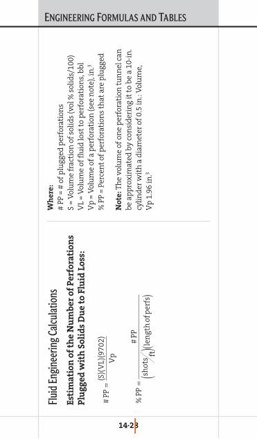
ENGINEERING FORMULAS AND TABLES
14·28
Flui
d Eng
inee
ring C
alcul
atio
nsE
stim
ati
on
of
the
Nu
mb
er
of
Pe
rfo
rati
on
s
Plu
gg
ed
wit
h S
oli
ds
Du
e t
o F
luid
Lo
ss:
Wh
ere
:
# PP
= #
of p
lugg
ed p
erfo
rati
ons
S =
Vol
um
e fr
acti
on o
f sol
ids
(vol
% s
olid
s/10
0)V
L =
Vol
um
e of
flu
id lo
st t
o p
erfo
rati
ons,
bbl
Vp
= V
olu
me
of a
per
fora
tion
(see
not
e), i
n.3
% P
P =
Perc
ent
of p
erfo
rati
ons
that
are
plu
gged
No
te:
The
volu
me
of o
ne
per
fora
tion
tu
nn
el c
anbe
app
roxi
mat
ed b
y co
nsi
der
ing
it t
o be
a 1
0-in
.cy
lin
der
wit
h a
dia
met
er o
f 0.5
in.:
Vol
um
e,V
p1.
96in
.3 %
PP=
#PP
shot
s ft(
)len
gth
ofp
erfs
()
#PP
=(S
)(V
L)(9
702)
Vp
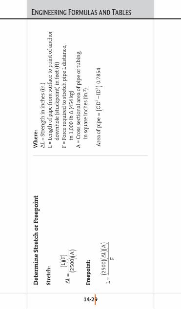
ENGINEERING FORMULAS AND TABLES
14·29
De
term
ine
Str
etc
h o
r F
ree
po
int
Str
etc
h:
Fre
ep
oin
t:
Wh
ere
:
∆L
= St
ren
gth
in in
ches
(in
.)L
= Le
ngt
h o
f pip
e fr
om s
urf
ace
to p
oin
t of
an
chor
dow
nh
ole
(stu
ckp
oin
t) in
feet
(ft)
F =
Forc
e re
quir
ed t
o st
retc
h p
ipe
L d
ista
nce
, in
1,0
00 lb
∆ (4
54 k
g)A
= C
ross
sec
tion
al a
rea
of p
ipe
or t
ubi
ng,
in
squ
are
inch
es (i
n.2 )
Are
aof
pip
e=
OD
2–
ID2
()0
.785
4
L=
2500
()∆
L ()A (
)F
∆L
=L ()
F ()25
00(
)A ()
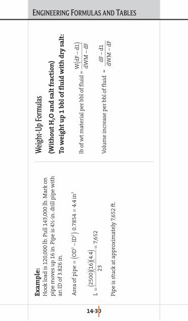
ENGINEERING FORMULAS AND TABLES
14·30
Ex
am
ple
:H
ook
load
is 1
20,0
00 lb
. Pu
ll 14
3,00
0 lb
. Mar
k on
pip
e m
oves
up
16
in. P
ipe
is 4
∑-i
n. d
rill
pip
e w
ith
an ID
of 3
.826
in.
Pip
e is
stu
ck a
t ap
pro
xim
atel
y 7,
652
ft.
Weig
ht-U
p For
mul
as(W
ith
ou
t H
2O
an
d s
alt
fra
ctio
n)
To
we
igh
t u
p 1
bb
l o
f fl
uid
wit
h d
ry s
alt
:
lb o
f wt
mat
eria
l per
bbl
of f
luid
=
Vol
um
e in
crea
se p
er b
bl o
f flu
id=
dF
−d1
dW
M−
dF
Wd
F−
d1(
)d
WM
−d
F
L=
2500
()1
6 ()4
.4 ()
23=
7,65
2
Are
aof
pip
e=
OD
2−
ID2
()0
.785
4=
4.4
in2
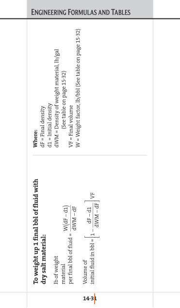
ENGINEERING FORMULAS AND TABLES
14·31
To
we
igh
t u
p 1
fin
al
bb
l o
f fl
uid
wit
h
dry
sa
lt m
ate
ria
l:
lb o
f wei
ght
mat
eria
l p
er fi
nal
bbl
of f
luid
=
Vol
um
e of
in
itia
l flu
id in
bbl
=
Wh
ere
:
dF
= Fi
nal
den
sity
d1
= In
itia
l den
sity
dW
M =
Den
sity
of w
eigh
t m
ater
ial,
lb/g
al(S
ee t
able
on
pag
e 15
·32)
VF
= Fi
nal
vol
um
eW
= W
eigh
t fa
ctor
, lb/
bbl (
See
tabl
e on
pag
e 15
·32)
1−
dF
−d1
dW
M−
dF
⎡ ⎣ ⎢ ⎤ ⎦ ⎥
VF
Wd
F−
d1(
)d
WM
−d
F

ENGINEERING FORMULAS AND TABLES
14·32
Sp
eci
fic
lb/g
al
lb/b
bl
Sa
ckW
eig
hti
ng
Ag
en
tsG
rav
ity
(SG
*8
.33
4)
(lb
/ga
l *
42
)S
ack
s/b
bl
wt/
lb
Bar
ite
4.2
351,
470
14.7
100
Cal
ciu
m C
arbo
nat
e2.
823
.35
981
19.6
50
Cal
ciu
m B
rom
ide
3.35
327
.96
1,17
421
.355
Cal
ciu
m C
hlo
rid
e1.
6814
588
7.4
80
Pota
ssiu
m C
hlo
rid
e1.
988
16.6
696
13.9
507.
010
0
Pota
ssiu
m F
orm
ate
1.91
15.9
669
12.2
55
Sod
ium
Ch
lori
de
2.16
318
.075
87.
610
0
Sod
ium
Bro
mid
e3.
205
26.7
1,12
320
.455
Sod
ium
For
mat
e1.
919
1667
212
.255
Zin
c B
rom
ide
4.21
935
.21,
478
14.8
100
Am
mon
ium
Ch
lori
de
1.54
12.8
453
910
.850
Ces
ium
For
mat
e2.
420
841
8.4
100
De
nsi
tie
s o
f W
eig
hti
ng
Ag
en
ts

ENGINEERING FORMULAS AND TABLES
14·33
Am
mon
ium
Ch
lori
de
NH
4Cl
8.90
1.06
7
Sod
ium
Ch
lori
de
NaC
l10
.01.
2
Cal
ciu
m C
hlo
rid
eC
aCl 2
11.8
1.41
Cal
ciu
m C
hlo
rid
e/C
aCl 2
/CaB
r 215
.11.
81C
alci
um
Bro
mid
e
Pota
ssiu
m C
hlo
rid
eK
Cl
9.8
1.17
5
Sod
ium
Bro
mid
eN
aBr
12.7
1.52
Cal
ciu
m B
rom
ide
CaB
r 215
.31.
83
Zin
c B
rom
ide
ZnB
r 2/C
aBr
19.2
2.30
ZnB
r 220
.52.
46
Sod
ium
For
mat
eN
aCO
OH
11.0
1.32
Pota
ssiu
m F
orm
ate
KC
OO
OH
13.1
1.57
Ces
ium
For
mat
eC
sCO
OH
19.9
2.38
6
Not
e: D
o n
ot u
se th
ese
den
siti
es w
ith
out r
efer
rin
g to
the
brin
e ta
bles
for
crys
talli
zati
on p
oin
ts.
Bri
ne
s a
nd
Ma
xim
um
De
nsi
tie
s

ENGINEERING FORMULAS AND TABLES
14·34
Flu
id V
elo
city
(V
):
Pip
e:
An
nu
lus:
Wh
ere
:
Q =
flow
rat
e (g
al/m
in)
Vp
= fl
uid
vel
ocit
y in
pip
e, ft
/sec
Va
= fl
uid
vel
ocit
y in
an
nu
lus,
ft/s
ecD
2=
ID c
asin
g or
ou
ter
ann
ulu
s w
all (
in.)
D1
= O
D o
f tu
bin
g or
inn
er a
nn
ulu
s (i
n.)
Hydr
aulic
Calc
ulat
ions
for
Non-
New
toni
an Fl
uids
Fri
ctio
n L
oss
in
Pip
e:
Wh
ere
:
P p=
pre
ssu
re lo
ss in
pip
e (p
si)
L m=
mea
sure
d d
epth
or
len
gth
of p
ipe
(ft)
P p/L
m=
psi
/ft
pre
ssu
re lo
ssf p
= fr
icti
on fa
ctor
for
pip
eV
p=
flow
vel
ocit
y in
pip
e (f
t/se
c)d
= d
ensi
ty (l
b/ga
l)ID
= ID
of p
ipe
(in
.)
Vp
=0.
408
Q ()
ID2
Va
=0.
408
Q ()
D2()2
−D
1()2
P p
L m
=f p
Vp()2
d
25.8
1ID (
)
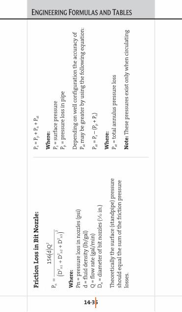
ENGINEERING FORMULAS AND TABLES
14·35
Fri
ctio
n L
oss
in
Bit
No
zzle
:
Wh
ere
:
Pn =
pre
ssu
re lo
ss in
noz
zles
(psi
)d
= fl
uid
den
sity
(lb/
gal)
Q =
flow
rat
e (g
al/m
in)
Dn
= d
iam
eter
of b
it n
ozzl
es (1 ⁄3
2in
.)
Theo
reti
cally
th
e su
rfac
e (s
tan
dpip
e) p
ress
ure
shou
ld e
qual
th
e su
m o
f th
e fr
icti
on p
ress
ure
loss
es.
P s=
P p+
P n+
P at
Wh
ere
:
P s=
surf
ace
pre
ssu
reP p
= p
ress
ure
loss
in p
ipe
Dep
end
ing
on w
ell c
onfi
gura
tion
th
e ac
cura
cy o
fP a
tm
ay b
e gr
eate
r by
usi
ng
the
follo
win
g eq
uat
ion
:
P at=
P s–
(Pp
+ P n
)
Wh
ere
:
P at=
tota
l an
nu
lus
pre
ssu
re lo
ss
No
te:
Thes
e p
ress
ure
s ex
ist
only
wh
en c
ircu
lati
ng
P n=
156
d ()Q
2
D2
n1
+D
2n
2+
D2
n3
()2

ENGINEERING FORMULAS AND TABLES
14·36
Hy
dro
sta
tic
Pre
ssu
re G
rad
ien
t:
Hyd
rost
atic
pre
ssu
re P
h=
0.05
2(d
)(L v
)
Hyd
rost
atic
pre
ssu
re g
rad
ien
t P h
/Lv
= 0.
052(
d)
Wh
ere
:
P h=
hyd
rost
atic
pre
ssu
re (p
si)
L v=
Tru
e V
erti
cal D
epth
(TV
D) (
ft)
d =
den
sity
(lb/
gal)
P h/L
v=
hyd
rost
atic
pre
ssu
re g
rad
ien
t (p
si/f
t)
Cir
cula
tin
g P
ress
ure
Gra
die
nt
(Bo
tto
mh
ole
):
Cir
cula
tin
g p
ress
ure
Pc
= P h
+ P a
t
Cir
cula
tin
g p
ress
ure
gra
die
nt
Wh
ere
:
P c=
circ
ula
tin
g p
ress
ure
(psi
)P c
/L =
cir
cula
tin
g p
ress
ure
gra
die
nt
(psi
/ft)
L m=
len
gth
(ft)
or
mea
sure
d d
epth
(ft)
(to
dep
th o
f in
tere
st)
P c L=
P h Lv
+P at L m

ENGINEERING FORMULAS AND TABLES
14·37
Av
era
ge
Pre
ssu
re L
oss
or
To
tal
An
nu
lar
Pre
ssu
re G
rad
ien
t:
The
pre
ssu
re lo
ss is
cal
cula
ted
for
each
sec
tion
ofan
nu
lus
and
th
e av
erag
e p
ress
ure
loss
can
be
calc
ula
ted
as
follo
ws:
P a/L
= p
ress
ure
gra
die
nt,
psi
/ft
L =
mea
sure
d d
epth
or
dep
th o
f in
tere
st, f
t
P at/
L m=
(Pa1
/L1)
L1
+ (P
a2/L
2) L
2+
(Pa3
/L3)
L3
...
L m
This
can
als
o be
cal
led
th
e to
tal a
nn
ula
rp
ress
ure
grad
ien
t:
P at=
tota
l an
nu
lus
pre
ssu
re lo
ssP a
t=
P a1
+ P a
2+
P a3
+. .
.+
P an
L m=
mea
sure
d d
epth
or
len
gth
of p
ipe

ENGINEERING FORMULAS AND TABLES
14·38
Po
we
r L
aw
Mo
de
l:τ
= Kγn
wh
ere
K a
nd
n a
re t
he
valu
es o
f in
tere
st
n =
flow
beh
avio
r in
dex
K =
con
sist
ency
ind
exτ
= sh
ear
stre
ssγ
= sh
ear
rate
For
600
and
300
rp
m r
ead
ings
:
Wh
ere
:n
p=
n fo
r p
ipe
Wh
ere
: K
p=
K fo
r p
ipe
Wh
ere
: n
a=
n fo
r an
nu
lus
Wh
ere
: R
3=
3 rp
m r
ead
ing
Wh
ere
: K
a=
K fo
r an
nu
lus
np
=3
.32
log
R60
0
R30
0
⎡ ⎣ ⎢ ⎤ ⎦ ⎥
Kp
=5.
1R
300
()
511
np
na
=0.
5lo
gR
300
R3
⎡ ⎣ ⎢ ⎤ ⎦ ⎥
Ka
=5.
1R
300
()
511
na
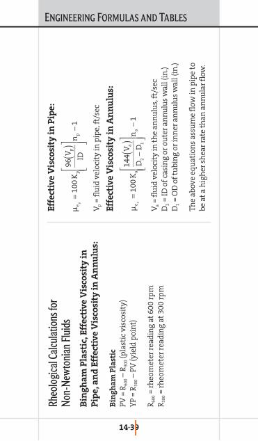
ENGINEERING FORMULAS AND TABLES
14·39
Rheo
logi
cal C
alcul
atio
ns fo
r No
n-Ne
wto
nian
Flui
dsB
ing
ha
m P
last
ic, E
ffe
ctiv
e V
isco
sity
in
Pip
e, a
nd
Eff
ect
ive
Vis
cosi
ty i
n A
nn
ulu
s:
Bin
gh
am
Pla
stic
PV =
R60
0–
R30
0(p
last
ic v
isco
sity
)Y
P =
R30
0–
PV (y
ield
poi
nt)
R60
0=
rheo
met
er r
ead
ing
at 6
00 r
pm
R30
0=
rheo
met
er r
ead
ing
at 3
00 r
pm
Eff
ect
ive
Vis
cosi
ty i
n P
ipe
:
Vp
= fl
uid
vel
ocit
y in
pip
e, ft
/sec
Eff
ect
ive
Vis
cosi
ty i
n A
nn
ulu
s:
Va
= fl
uid
vel
ocit
y in
th
e an
nu
lus,
ft/s
ecD
2=
ID o
f cas
ing
or o
ute
r an
nu
lus
wal
l (in
.)D
1=
OD
of t
ubi
ng
or in
ner
an
nu
lus
wal
l (in
.)
The
abov
e eq
uat
ion
s as
sum
e fl
ow in
pip
e to
be
at
a h
igh
er s
hea
r ra
te t
han
an
nu
lar
flow
.
µe
p=
100
Kp
96V
p()
ID
⎡ ⎣ ⎢ ⎢
⎤ ⎦ ⎥ ⎥ np
−1
µe
a=
100
Ka
144
Va()
D2
−D
1
⎡ ⎣ ⎢ ⎢
⎤ ⎦ ⎥ ⎥ na
−1
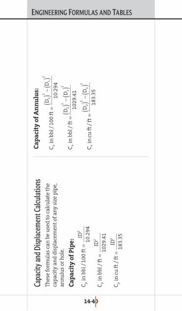
ENGINEERING FORMULAS AND TABLES
14·40
Capa
city a
nd D
isplac
emen
t Calc
ulat
ions
Thes
e fo
rmu
las
can
be
use
d t
o ca
lcu
late
th
eca
pac
ity
and
dis
pla
cem
ent
of a
ny
size
pip
e,an
nu
lus
or h
ole.
Ca
pa
city
of
Pip
e:
Ca
pa
city
of
An
nu
lus:
Cp
inb
bl/
100
ft=
ID2
10.2
94
Cp
inb
bl/
ft=
ID2
1029
.41
Cp
incu
ft/
ft=
ID2
183.
35
Ca
inb
bl/
100
ft=
D2()2
−D
1()2
10.2
94
Ca
inb
bl/
ft=
D2()2
−D
1()2
1029
.41
Ca
incu
ft/
ft=
D2()2
−D
1()2
183.
35
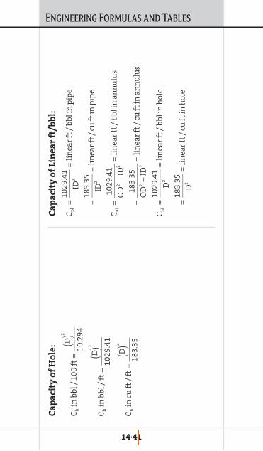
ENGINEERING FORMULAS AND TABLES
14·41
Ca
pa
city
of
Ho
le:
Ca
pa
city
of
Lin
ea
r ft
/bb
l:
Ch
inb
bl/
100
ft=
D ()2
10.2
94
Ch
inb
bl/
ft=
D ()2
1029
.41
Ch
incu
ft/
ft=
D ()2
183.
35
Cp
l=
1029
.41
ID2
=li
nea
rft
/b
bli
np
ipe
=18
3.35
ID2
=li
nea
rft
/cu
ftin
pip
e
Cal
=10
29.4
1
OD
2−
ID2
=li
nea
rft
/b
bli
nan
nu
lus
=18
3.3
5
OD
2−
ID2
=li
nea
rft
/cu
ftin
ann
ulu
s
Ch
l=
1029
.41
D2
=li
nea
rft
/b
bli
nh
ole
=18
3.35
D2
=li
nea
rft
/cu
ftin
hol
e

ENGINEERING FORMULAS AND TABLES
14·42
Op
gal/
stk
()=
cyli
nd
erca
pac
ity
×#
ofcy
lin
der
s×
%ef
fici
ency
100
Pum
p Out
put
Use
th
ese
form
ula
s in
con
jun
ctio
n w
ith
th
e p
um
p o
utp
ut
tabl
e to
det
erm
ine
pu
mp
ou
tpu
t.
No
te:
1. 1
str
oke
(stk
) = 1
com
ple
te c
ycle
2. D
oubl
e ac
tion
pu
mp
s lo
se t
he
rod
cap
acit
y du
rin
g ∑
of t
he
stro
ke.
3. C
ylin
der
an
d r
od c
apac
ity
is t
aken
from
th
e p
um
p o
utp
ut
tabl
e or
cal
cula
ted
by
usi
ng
the
form
ula
bel
ow.
Sin
gle
Act
ion
Pu
mp
s:
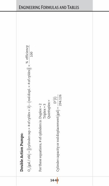
ENGINEERING FORMULAS AND TABLES
14·43
Do
ub
le A
ctio
n P
um
ps:
For
thes
e eq
uat
ion
s, #
of c
ylin
der
s is
: Du
ple
x =
2Tr
iple
x =
3Q
uin
tup
lex
=
Op
gal/
stk
()=
cyli
nd
erca
p.×
#of
cyld
rs×
2(
)−ro
dd
isp
l.×
#of
cyld
rs(
)[
]×%
effi
cien
cy10
0
Cy
lin
der
cap
acit
yor
rod
dis
pla
cem
ent
gal
()=
D2
l ()29
4.1
26

ENGINEERING FORMULAS AND TABLES
14·44
Pu
mp
Ou
tpu
t in
bb
l/m
in:
(bbl
/ft
take
n fr
om p
ipe
tabl
es)
Op
= p
um
p o
utp
ut,
gal
/stk
Q =
flow
rat
e, ft
/min
D =
dia
met
er, i
n.
l = c
ylin
der
or
rod
len
gth
, in
.
Op
bb
l/m
in(
)=O
p
gal
stk
⎛ ⎝ ⎜ ⎞ ⎠ ⎟ ×
stk
min
⎛ ⎝ ⎜ ⎞ ⎠ ⎟ ×
1b
bl
42ga
l
⎛ ⎝ ⎜ ⎞ ⎠ ⎟
Flow
rate
Q ()f
t/m
in(
)pip
eor
ann
ulu
s(
)=Q
=b
bl
min
⎛ ⎝ ⎜ ⎞ ⎠ ⎟ ×
ft bb
l
⎛ ⎝ ⎜ ⎞ ⎠ ⎟

ENGINEERING FORMULAS AND TABLES
14·45
H=
∆PK
A
1279
µQ
H=
∆PK
A2
1279
µQ
A+
4.6
3ρQ
2K
0.4
5
Darc
y’s Sa
nd H
eight
Calc
ulat
ion
for N
on-T
urbu
lent F
low
Wh
ere
:
H =
hei
ght
of fi
ll, ft
∆P
= fl
owin
g d
iffe
ren
tial
pre
ssu
reK
= g
rave
l per
mea
bili
ty, d
arci
esA
= c
ross
-sec
tion
al fl
ow a
rea,
ft2
µ =
flu
id v
isco
sity
, cp
Q =
flow
rat
e, b
bl/m
in
Forc
heim
er’s
Sand
Heig
ht C
alcul
atio
n fo
r Tur
bulen
t Flo
w
Wh
ere
:
H =
hei
ght
of fi
ll, ft
∆P
= fl
owin
g d
iffe
ren
tial
pre
ssu
reρ
= fl
uid
den
sity
, lb/
gal
K =
gra
vel p
erm
eabi
lity
, dar
cies
A =
cro
ss-s
ecti
onal
flow
are
a, ft
2
µ =
flu
id v
isco
sity
, cp
Q =
flow
rat
e, b
bl/m
in
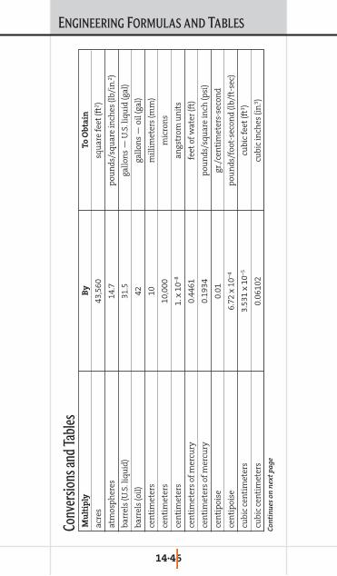
ENGINEERING FORMULAS AND TABLES
14·46
Mu
ltip
lyB
yT
o O
bta
in
acre
s43
,560
squ
are
feet
(ft2 )
atm
osp
her
es14
.7p
oun
ds/
squ
are
inch
es (l
b/in
.2 )
barr
els
(U.S
. liq
uid
)31
.5ga
llon
s —
U.S
. liq
uid
(gal
)
barr
els
(oil
)42
gallo
ns
— o
il (g
al)
cen
tim
eter
s10
mil
lim
eter
s (m
m)
cen
tim
eter
s10
,000
mic
ron
s
cen
tim
eter
s1.
x 1
0–8an
gstr
om u
nit
s
cen
tim
eter
s of
mer
cury
0.44
61fe
et o
f wat
er (f
t)
cen
tim
eter
s of
mer
cury
0.19
34p
oun
ds/
squ
are
inch
(psi
)
cen
tip
oise
0.01
gr./
cen
tim
eter
s-se
con
d
cen
tip
oise
6.72
x 1
0–4p
oun
ds/
foot
-sec
ond
(lb/
ft-s
ec)
cubi
c ce
nti
met
ers
3.53
1 x
10–5
cubi
c fe
et (f
t3 )
cubi
c ce
nti
met
ers
0.06
102
cubi
c in
ches
(in
.3 )
Conv
ersio
ns an
d Tab
les
Con
tin
ues
on
nex
t p
age

ENGINEERING FORMULAS AND TABLES
14·47
Mu
ltip
lyB
yT
o O
bta
in
cubi
c ce
nti
met
ers
2.64
2 x
10–4
gallo
ns
— U
.S. l
iqu
id (g
al)
cubi
c ce
nti
met
ers
1.0
x 10
–3li
ters
(L)
cubi
c fe
et17
28cu
bic
inch
es (i
n.3 )
cubi
c fe
et0.
0283
2cu
bic
met
ers
(m3 )
cubi
c fe
et0.
0370
4cu
bic
yard
s
cubi
c fe
et7.
4805
2ga
llon
s —
U.S
. liq
uid
(gal
)
cubi
c fe
et28
.32
lite
rs (L
)
cubi
c fe
et/m
inu
te0.
1247
gallo
ns/
seco
nd
(gal
/sec
)
cubi
c fe
et/m
inu
te0.
472
lite
rs/s
econ
d (L
/sec
)
cubi
c m
eter
s35
.31
cubi
c fe
et (f
t3 )
cubi
c m
eter
s61
,023
cubi
c in
ches
(in
.3 )
cubi
c m
eter
s1.
308
cubi
c ya
rds
cubi
c m
eter
s26
4.2
gallo
ns
— U
.S. l
iqu
id (g
al)
Con
tin
ues
on
nex
t p
age
Con
tin
ued
from
pre
viou
s p
age

ENGINEERING FORMULAS AND TABLES
14·48
Mu
ltip
lyB
yT
o O
bta
in
cubi
c ya
rds
27cu
bic
feet
(ft3 )
cubi
c ya
rds
202
gallo
ns
— U
.S. l
iqu
id (g
al)
fath
oms
6.0
feet
(ft)
feet
30.4
8ce
nti
met
ers
(cm
)
feet
0.30
48m
eter
s (m
)
feet
/min
ute
0.01
667
feet
/sec
ond
(ft/
sec)
gallo
ns
3785
cubi
c ce
nti
met
ers
(cm
3 )
gallo
ns
0.13
37cu
bic
feet
(ft3 )
gallo
ns
231
cubi
c in
ches
(in
.3 )
gallo
ns
3.78
5 x
10–3
cubi
c m
eter
s (m
3 )
gallo
ns
3.78
5li
ters
(L)
gallo
ns
of w
ater
8.33
pou
nd
s of
wat
er (l
b)
gallo
ns/
min
ute
2.22
8 x
10–3
cubi
c fe
et/s
econ
d (f
t3 /se
c)
Con
tin
ues
on
nex
t p
age
Con
tin
ued
from
pre
viou
s p
age

ENGINEERING FORMULAS AND TABLES
14·49
Mu
ltip
lyB
yT
o O
bta
in
gallo
ns/
min
ute
8.02
08cu
bic
feet
/hou
r (f
t3 /h
r)
gram
s0.
0352
7ou
nce
s (o
z)
gram
s2.
205
x 10
–3p
oun
ds
(lb)
gram
s/cu
bic
cen
tim
eter
s62
.43
pou
nd
s/cu
bic
foot
(lb/
ft3 )
gram
s/cu
bic
cen
tim
eter
s0.
0361
3p
oun
ds/
cubi
c in
ches
(lb/
in.3 )
gram
s/li
ter
0.06
227
pou
nd
s/cu
bic
foot
(lb/
ft3 )
gram
s/sq
uar
e ce
nti
met
ers
2.04
81p
oun
ds/
squ
are
foot
(lb/
ft2 )
inch
es2.
54ce
nti
met
ers
(cm
)
inch
es o
f mer
cury
1.13
3fe
et o
f wat
er (f
t)
inch
es o
f mer
cury
0.49
12p
oun
ds/
squ
are
inch
(lb/
in.2 )
kilo
gram
s10
00gr
ams
(g)
kilo
gram
s2.
2046
pou
nd
s (l
b)
kilo
gram
s1.
102
x 10
–3to
ns
— s
hor
t (t
ons)
Con
tin
ues
on
nex
t p
age
Con
tin
ued
from
pre
viou
s p
age

ENGINEERING FORMULAS AND TABLES
14·50
Mu
ltip
lyB
yT
o O
bta
in
kilo
gram
s/cu
bic
met
er0.
0624
3p
oun
ds/
cubi
c ft
(lb/
ft3 )
kilo
gram
s/cu
bic
met
er3.
613
x 10
–5p
oun
ds/
cubi
c in
ch (l
b/in
.3 )
kilo
gram
s/sq
uar
e ce
nti
met
ers
2048
pou
nd
s/sq
uar
e fo
ot (l
b/ft
2 )
kilo
gram
s/sq
uar
e ce
nti
met
ers
14.2
2p
oun
ds/
squ
are
inch
(lb/
in.2 )
kilo
gram
s/sq
uar
e m
eter
0.20
48p
oun
ds/
squ
are
foot
(lb/
ft2 )
kilo
gram
s/sq
uar
e m
eter
1.42
2 x
10–3
pou
nd
s/sq
uar
e in
ch (l
b/in
.2 )
knot
s60
76fe
et/h
our
(ft/
hr)
knot
s1.
0n
auti
cal m
iles
/hou
r (m
ph
)
knot
s1.
151
stat
ute
mil
es/h
our
(mp
h)
lite
rs0.
2642
gallo
ns
— U
.S. l
iqu
id (g
al)
lite
rs1.
057
quar
ts —
U.S
. liq
uid
(qt)
lite
rs/m
inu
te5.
886
x 10
–4cu
bic
feet
/sec
ond
(ft3 /
sec)
lite
rs/m
inu
te4.
403
x 10
–3ga
llon
s/se
con
d (g
al/s
ec)
Con
tin
ues
on
nex
t p
age
Con
tin
ued
from
pre
viou
s p
age

ENGINEERING FORMULAS AND TABLES
14·51
Mu
ltip
lyB
yT
o O
bta
in
met
ers
3.28
1fe
et (f
t)
met
ers
1.0
x 10
–3ki
lom
eter
s (k
m)
met
ers
39.3
7in
ches
(in
.)
met
ers/
min
ute
3.28
1fe
et/m
inu
te (f
t/m
in)
met
ers/
min
ute
0.05
468
feet
/sec
ond
(ft/
sec)
met
ers/
min
ute
0.03
728
mil
es/h
our
(mp
h)
met
ers/
seco
nd
196.
8fe
et/m
inu
te (f
t/m
in)
met
ers/
seco
nd
3.28
1fe
et/s
econ
d (f
t/se
c)
mic
rom
icro
ns
1.0
x 10
–12
met
ers
(m)
mic
ron
s1.
0 x
10–6
met
ers
(m)
mil
es (n
auti
cal)
1.15
16m
iles
, sta
tute
mil
es (s
tatu
te)
5280
feet
(ft)
mil
es (s
tatu
te)
1609
met
ers
(m)
Con
tin
ues
on
nex
t p
age
Con
tin
ued
from
pre
viou
s p
age
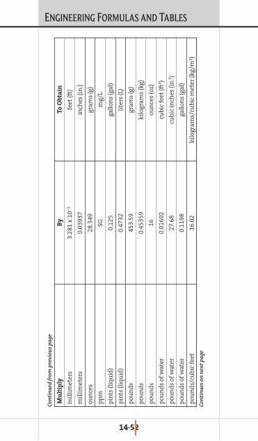
ENGINEERING FORMULAS AND TABLES
14·52
Mu
ltip
lyB
yT
o O
bta
in
mil
lim
eter
s3.
281
x 10
–3fe
et (f
t)
mil
lim
eter
s0.
0393
7in
ches
(in
.)
oun
ces
28.3
49gr
ams
(g)
pp
mSG
mg/
L
pin
ts (l
iqu
id)
0.12
5ga
llon
s (g
al)
pin
ts (l
iqu
id)
0.47
32li
ters
(L)
pou
nd
s45
3.59
gram
s (g
)
pou
nd
s0.
4535
9ki
logr
ams
(kg)
pou
nd
s16
oun
ces
(oz)
pou
nd
s of
wat
er0.
0160
2cu
bic
feet
(ft3 )
pou
nd
s of
wat
er27
.68
cubi
c in
ches
(in
.3 )
pou
nd
s of
wat
er0.
1198
gallo
ns
(gal
)
pou
nd
s/cu
bic
feet
16.0
2ki
logr
ams/
cubi
c m
eter
(kg/
m3 )
Con
tin
ues
on
nex
t p
age
Con
tin
ued
from
pre
viou
s p
age

ENGINEERING FORMULAS AND TABLES
14·53
Mu
ltip
lyB
yT
o O
bta
in
pou
nd
s/cu
bic
inch
es17
28p
oun
ds/
cubi
c fe
et (l
b/ft
3 )
pou
nd
s/fo
ot1.
488
kilo
gram
s/m
eter
(kg/
m)
pou
nd
s/sq
uar
e fo
ot4.
882
kilo
gram
s/sq
uar
e m
eter
(kg/
m2 )
pou
nd
s/sq
uar
e fo
ot6.
944
x 10
–3p
oun
ds/
squ
are
inch
(lb/
in.2 )
pou
nd
s/sq
uar
e in
ches
2.30
7fe
et o
f wat
er (f
t)
pou
nd
s/sq
uar
e in
ches
2.03
6in
ches
of m
ercu
ry (i
n.)
pou
nd
s/sq
uar
e in
ches
703.
1ki
logr
ams/
squ
are
met
er (k
g/m
2 )
pou
nd
s/sq
uar
e in
ches
144
pou
nd
s/sq
uar
e fo
ot (l
b/ft
2 )
pou
nd
s/sq
uar
e in
ches
0.07
03ki
logr
ams/
squ
are
cen
tim
eter
s (k
g/cm
2 )
quar
ts (l
iqu
id)
0.25
gallo
ns
(gal
)
quar
ts (l
iqu
id)
0.94
63li
ters
(L)
rod
s16
.5fe
et (f
t)
squ
are
cen
tim
eter
s1.
076
x 10
–3sq
uar
e fe
et (f
t2 )
Con
tin
ues
on
nex
t p
age
Con
tin
ued
from
pre
viou
s p
age
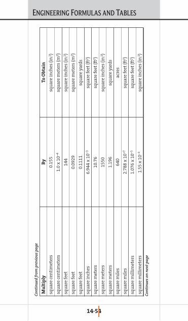
ENGINEERING FORMULAS AND TABLES
14·54
Mu
ltip
lyB
yT
o O
bta
in
squ
are
cen
tim
eter
s0.
155
squ
are
inch
es (i
n.2 )
squ
are
cen
tim
eter
s1.
0 x
10–4
squ
are
met
ers
(m2 )
squ
are
feet
144
squ
are
inch
es (i
n.2 )
squ
are
feet
0.09
29sq
uar
e m
eter
s (m
2 )
squ
are
feet
0.11
11sq
uar
e ya
rds
squ
are
inch
es6.
944
x 10
–3sq
uar
e fe
et (f
t2 )
squ
are
met
ers
10.7
6sq
uar
e fe
et (f
t2 )
squ
are
met
ers
1550
squ
are
inch
es (i
n.2 )
squ
are
met
ers
1.19
6sq
uar
e ya
rds
squ
are
mil
es64
0ac
res
squ
are
mil
es2.
788
x 10
+7sq
uar
e fe
et (f
t2 )
squ
are
mil
lim
eter
s1.
076
x 10
–5sq
uar
e fe
et (f
t2 )
squ
are
mil
lim
eter
s1.
55 x
10–3
squ
are
inch
es (i
n.2 )
Con
tin
ues
on
nex
t p
age
Con
tin
ued
from
pre
viou
s p
age

ENGINEERING FORMULAS AND TABLES
14·55
Mu
ltip
lyB
yT
o O
bta
in
squ
are
yard
s2.
066
x 10
–4ac
res
squ
are
yard
s9.
0sq
uar
e fe
et (f
t2 )
squ
are
yard
s12
96sq
uar
e in
ches
(in
.2 )
squ
are
yard
s0.
8361
squ
are
met
ers
(m2 )
squ
are
yard
s3.
228
x 10
–7sq
uar
e m
iles
ton
s (lo
ng)
2240
pou
nd
s (l
b)
ton
s (m
etri
c)10
00ki
logr
ams
(kg)
ton
s (s
hor
t)90
7.18
kilo
gram
s (k
g)
ton
s (s
hor
t)20
00p
oun
ds
(lb)
ton
s (s
hor
t)24
30Po
un
ds
— t
roy
Con
tin
ued
from
pre
viou
s p
age

Chapter 15LIST OF PRODUCTS
COMPLETION FLUIDSMANUAL
15. L IST
OFPRODUCTS

LIST OF PRODUCTS
15·1
Clear Brine Systems
Ammonium Chloride (dry)Calcium Bromide/Calcium Chloride Brine SystemCalcium Bromide Brine SystemCalcium Bromide (dry)Calcium Bromide (liquid)Calcium Chloride Brine SystemCalcium Chloride (dry)Calcium Chloride (liquid)Cesium Formate (liquid)Cesium Formate/Potassium Formate Brine SystemCesium Formate/Potassium Formate/
Sodium Formate Brine SystemPotassium Chloride Brine SystemPotassium Chloride (dry)Potassium Formate Brine SystemPotassium Formate (dry)Sodium Bromide Brine SystemSodium Bromide (dry)Sodium Bromide (liquid)Sodium Bromide/Sodium Chloride Brine SystemSodium Chloride Brine SystemSodium Chloride (dry)Sodium Formate Brine SystemSodium Formate (dry)Zinc Bromide/Calcium Bromide (liquid)Zinc Bromide/Calcium Bromide/Calcium Chloride
Brine SystemCesium Formate Brine System
Reservoir Drill-In Fluids Systems
FLOPRO NT Minimal solids, non-damaging WB RDF system
FLOPRO SF Solids-free, non-damagingWB RDF system
FLOTHRU Organophilic filter-cake system

LIST OF PRODUCTS
15·2
DIPRO High-density, biopolymer-free, divalent brine RDFsystem
VERSAPRO Oil-base RDF systemVERSAPRO LS Low-solids oil-base RDF
systemNOVAPRO Synthetic olefin-base RDF
systemFAZEPRO Reversible invert-emulsion
RDF system
Reservoir Drill-In Fluids Products
DI-ANTIFOAM Antifoaming agent for theDIPRO system
DI-BALANCE Viscosifier for the DIPROsystem
DI-BOOST Secondary viscosifier for theDIPRO system
DI-INHIB Shale inhibitor for theDIPRO system
DI-TROL Filtration-control agent forthe DIPRO system
DUAL-FLO Fluid-loss additive for theFLOPRO NT system
DUAL-FLO HT Fluid-loss reducer for high-temperature applications
FAZE-MUL Emulsifier for FAZEPRO systemFAZE-WET Wetting agent for FAZEPRO
systemFLO-TROL Starch derivative filtration
control agent for FLOPRO NTsystem
FLO-VIS L Pre-dispersed, clarifiedxanthan gum solution
FLO-VIS NT Non-dispersable, non-clarified xanthan gum
FLO-VIS PLUS Premium clarified xanthanfor FLOPRO NT system
FLO-WATE Sized-salt weighting agentfor FLOPRO NT system
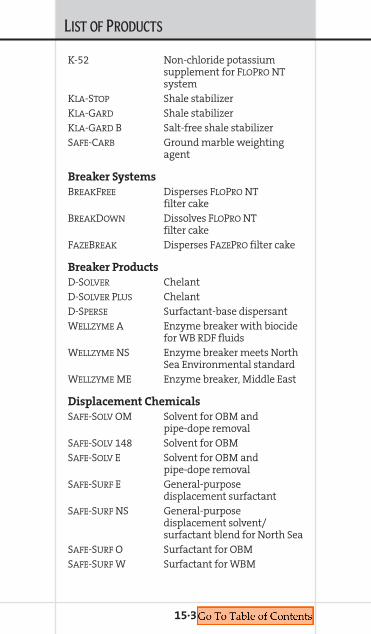
LIST OF PRODUCTS
15·3
K-52 Non-chloride potassiumsupplement for FLOPRO NTsystem
KLA-STOP Shale stabilizerKLA-GARD Shale stabilizerKLA-GARD B Salt-free shale stabilizerSAFE-CARB Ground marble weighting
agent
Breaker Systems
BREAKFREE Disperses FLOPRO NTfilter cake
BREAKDOWN Dissolves FLOPRO NTfilter cake
FAZEBREAK Disperses FAZEPRO filter cake
Breaker Products
D-SOLVER ChelantD-SOLVER PLUS ChelantD-SPERSE Surfactant-base dispersantWELLZYME A Enzyme breaker with biocide
for WB RDF fluidsWELLZYME NS Enzyme breaker meets North
Sea Environmental standardWELLZYME ME Enzyme breaker, Middle East
Displacement Chemicals
SAFE-SOLV OM Solvent for OBM andpipe-dope removal
SAFE-SOLV 148 Solvent for OBMSAFE-SOLV E Solvent for OBM and
pipe-dope removalSAFE-SURF E General-purpose
displacement surfactantSAFE-SURF NS General-purpose
displacement solvent/surfactant blend for North Sea
SAFE-SURF O Surfactant for OBMSAFE-SURF W Surfactant for WBM

LIST OF PRODUCTS
SAFE-SURF WN Water-base mud displacementsurfactant, North Sea
SAFE-T-PICKLE Pipe-dope solvent
Viscosifiers
DUO-VIS Xanthan gumDUO-VIS L Liquified xanthan gum,
non-clarifiedDUO-VIS PLUS NS Xanthan gum, non-
dispersible, non-clarifiedfor North Sea use
SAFE-LINK 110 Cross-linked cellulose polymerused to control brine losses
SAFE-LINK 140 Cross-linked cellulose polymerused to control high-densitybrine losses
SAFE-VIS Dry HECSAFE-VIS E Liquid HECSAFE-VIS LE Liquid HEC, North Sea versionSAFE-VIS HDE Liquid HEC for high-density
brinesSAFE-VIS OGS Specially formulated
liquid HEC
Corrosion Inhibitors
SAFE-COR Organic amine corrosioninhibitor
SAFE-COR C Organic amine corrosioninhibitor
SAFE-COR E Organic amine corrosioninhibitor
SAFE-COR HT High-temperature, thiocynatecorrosion inhibitor
SAFE-COR 220X Brine-soluble amide corrosioninhibitor
SAFE-SCAV CA Sulphur-free oxygenscavenger
SAFE-SCAV HS Zinc-free brine solubleH2S scavenger
SAFE-SCAV NA Oxygen scavenger
15·4
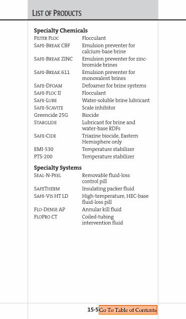
LIST OF PRODUCTS
Specialty Chemicals
FILTER FLOC FlocculantSAFE-BREAK CBF Emulsion preventer for
calcium-base brineSAFE-BREAK ZINC Emulsion preventer for zinc-
bromide brinesSAFE-BREAK 611 Emulsion preventer for
monovalent brinesSAFE-DFOAM Defoamer for brine systemsSAFE-FLOC II FlocculantSAFE-LUBE Water-soluble brine lubricantSAFE-SCAVITE Scale inhibitorGreencide 25G BiocideSTARGLIDE Lubricant for brine and
water-base RDFsSAFE-CIDE Triazine biocide, Eastern
Hemisphere onlyEMI-530 Temperature stabilizerPTS-200 Temperature stabilizer
Specialty Systems
SEAL-N-PEEL Removable fluid-losscontrol pill
SAFETHERM Insulating packer fluidSAFE-VIS HT LD High-temperature, HEC-base
fluid-loss pillFLO-DENSE AP Annular kill fluidFLOPRO CT Coiled-tubing
intervention fluid
15·5
THE PERIODIC TABLE OF ELEMENTS
79.9 Br e n i
m or B35
200.
6
Hg r u cr e
My
80
1.0 H
n e g or d y H 1
4.0 He m u i l e H
2
6.9 L
i m u i h t i L3
9.0 Be m u i l l yr e B 4
45.0 Sc m u i d n a c S 21
47.9 Ti
Tm u i n a t i
22
50.9 V
Vm u i d a n a
23
52.0 Cr m u i
m or h C 24
54.9 Mn e s e n a g n a
M 25
55.8 Fe n or I
26
58.9 Co t l a b o C
27
58.7 Ni l e k c i N
28
63.5 Cu r e p p o C
29
65.4 Zn c n i Z
30
10.8 B n or o B
5 27.0 Al m u i n i
m u l A 13 69.7 Ga m u i l l a G
31 114.
8 Inm u i d n I
49 204.
4 Tl m u i l l a h T
81
72.6 Ge m u i n a
mr e G 32 118.
7
Sn
Tn i
50 207.
2
Pb d a e L
82
74.9 As c i n e s r A
33 121.
8
Sb y n o
m i t n A 51 209.
0 Bi h t u
m s i B83
79.0 Se m u i n e l e S 34 12
7.6 Te T
m u i r u l l e52 (2
10)
Po m u i n o l o P 84
126.
9 I e n i d o I53 (2
10) At e n i t a t s A
85
28.1 Si n o c i l i S
14
31.0 P
s ur o h p s o h P 15
32.1 S
r u h p l u S16
12.0 C
n o b r a C6
14.0 N
n e g or t i N7
16.0 O
n e g y x O8
19.0 F e n i r o u l F
9 35.5 Cl e n i r o l h C
17
39.9 Ar n o gr A
18 83.8 Kr n o t p yr K
36 131.
3
Xe n o n e X
54 (222
)
Rn n o d a R
8620.2 Ne n o e N
10
88.9 Y m u i r t t Y
39
91.2 Zr m u i n o cr i Z 40
92.9 Nb m u i b o i N
41
95.9
o M
m u n e d b y l o M 42
(99) Tc T
m u i t e n h c e 43
101.
1
Ru m u i n e h t u R 44
102.
9
Rh m u i d o h R
45
106.
4
Pd m u i d a l l a P 46
107.
9
Ag r e v l i S
47
112.
4
Cd m u i
m d a C 4813
8.9
La m u n a h t n a L 57
178.
5 Hf m u i n f a H
72
181.
0 Ta Tm u l a t n a
73
183.
9 W Tn e t s g n u
74
186.
2
Re m u i n e h R
75
190.
2
Os m u i
m s O76
192.
2 Ir m u i d i r I77
(227
)
Ac m u i n i t c A 89
(261
) Rf
r e h t u Rr o f
m u i d10
4
(262
)
Db m u i n b u D 10
5
(263
) g S
r o b a e Sm u i g
106
(262
)
Bh m u i r h o B
107
(265
)
Hs m u i s s a H
108
(266
)
Mt m u i r e n t i e
M 109
195.
1 Pt m u n i t a l P
78
197.
0
Au d l o G
79
23.0 Na m u i d o S
11
24.3 Mg m u i s e n g a
M 1239
.1 Km u i s s a t o P 19
40.1 Ca m u i c l a C
2085
.5 Rb m u i d i b u R 37
87.6 Sr m u i t n or t S 38
132.
9
Cs m u i s e a C
55
137.
3
Ba m u i r a B
56(2
23) Fr m u i c n a r F 87
(226
)
Ra m u i d a R
88
* †
2
34
56
78
910
1112
1314
1516
17
181
Rel
ativ
e at
omic
mas
s
Key
Tho
se n
umbe
rs a
ppea
ring
with
in b
rack
ets
are
the
mas
s nu
mbe
rs o
f com
mon
isot
opes
Tho
se e
lem
ents
und
erlin
ed a
re r
adio
activ
e
Nel
emen
t is
a ga
s
Hg
elem
ent i
s a
liqui
d
at r
oom
tem
pera
ture
and
pre
ssur
e
Li
elem
ent i
s a
solid
Sym
bol
Ato
mic
num
ber
}
1 2 3 4 5 6 7
Con
tin
ues
on
nex
t p
age

THE PERIODIC TABLE OF ELEMENTS
H
140.
1
Ce m u i r e C
58
140.
9 Pr m u i m y d o e s a r P 59
232.
0
Th m u i r o h T
90
(231
)
Pa
r Pm u i n i t c a t o
91
144.
2
Nd m u i m y d o e N 60 23
8.1 U m u i n a r U
92
(147
) m P r Pm u i h t e
m o61 (2
37)
Np m u i n u t p e N 93
150.
4 m Sm u i r a
m a S 62 (244
) u P
m u i n o t u l P 94
152.
0 u E
m u i p or u E 63 (243
) m A
m u i c i r e m A 95
157.
3 d G
m u i n i l o d a G 64 (247
) m C
m u i r u C96
158.
9 b T Tm u i b r e
65 (247
) k B
m u i l e k r e B 97
162.
5
Dy m u i s or p s y D 66 (2
51) f
C r o f i l a Cm u i n
98
164.
9 o H
m u i m l o H 67 (2
52) s E
m u i n i e t s n i E 99
167.
3 r E
m u i b r E68 (2
57) m F r e F
m u i m
100
168.
9 m Tm u i l u h T
69 (258
) d M
m u i v e l e d n e M 10
1
173.
0 b Y
m u i b r e t t Y 70 (259
) o N
m u i l e b o N 102
175.
0 u Lm u i t e t u L
71 (260
) r L r w a L
m u i c n e10
3He
NO
F Cl
Ar
Kr
Xe
Rn
Ne
N
*58
-71
Lan
than
ide
seri
es
†90
-103
Act
inid
e se
ries
Con
tin
ued
from
pre
viou
s p
age
NOTICE
The information and data contained herein andall interpretations and/or recommendationsmade in connection therewith, whether writ-ten herein or elsewhere, or presented orally,have been carefully prepared and considered. Itmust be understood, however, that in additionto the necessity for relying on facts and sup-porting services furnished by others, there aremany variable well conditions of and overwhich M-I SWACO can have no knowledge orcontrol. Therefore, the information and dataand all interpretations and/or recommen-dations made in connection therewith are pre-sented solely as a guide, for the user’sconsideration, investigation and verification,and no warranties of any kind, express orimplied, are made in connection therewith. Inthese premises and in consideration thereof,any user of such information, data, interpreta-tions and/or recommendations agrees toindemnify and save harmless M-I SWACO fromall claims and actions for loss, damages, deathor injury, to persons or property, including,without limitation, subsurface damage, subsur-face trespass, or injury to the well or reservoir,allegedly, based on or arising out of use of same,whether or not such claims or actions are basedupon the purported negligence of M-I SWACO inthe preparation of furnishing the same.
The user’s agreement to indemnify and saveharmless M-I SWACO hereunder shall apply infavor of all its affiliates, subsidiaries, branchesand divisions, as well as to any contributionhereto to whom it or they may be liable in theabsence of this notice.

©2005 M-I L.L.C. All rights reserved. CMC.0306.0605.R1 (E) 1M Litho in U.S.A.
P.O. Box 42842Houston, Texas 77242-2842
Tel: 281·561·1300Fax: 281·561·1441
www.miswaco.comE-mail: [email protected]
Technology Centers:
HOUSTON, TEXASTel: 281·561·1300 · Fax: 281·561·1441
ABERDEEN, SCOTLANDTel: 44·1224·334634 · Fax: 44·1224·334650
STAVANGER, NORWAYTel: 47·51·577300 · Fax: 47·51·570605
This information is supplied solely for informational purposes and M-I SWACO makes noguarantees or warranties, either expressed or implied, with respect to the accuracy and useof this data. All product warranties and guarantees shall be governed by the Standard Termsof Sale. Nothing in this document is legal advice or is a substitute for competent legal advice.