completion report on the tower shielding facility
TRANSCRIPT

y
ORHLCutral FiI.. H••Nt
5$.1.165
,.. r:!o -- - ,.,.'. '
OPERATED ....
BY THE
POST O"'~ICE .OK P
OAK RIOGIE: TENNESSEE
C1.ur.roCU. c.'~i.1!:I
Dt.T£ :6.-lz.-:"i1J
~.l,r.~ 1{111ut1JT
~r~l1i1llifU"ii
COMPLETIOH REPORT OH THE TOWER SHIELOING FACILITY
OAK RIDGE NATIONAL. LABORATORY
CARBIDE AND CARBON CHEMICAL.S COMPANY

COPY NO.
Contract No. W-7405-eng-26
ORNLCentral Files Number
55-1.165
SP
COMPLETION REPORT ON THE TOWER SHIELDING FACILITY
by the
Engineering and Mechanical Division
DATE ISSUED
FEB 11 1955
OAK RIDGE NATIONAL LABORATORYOperated by
CARBIDE AND CARBON CHEMICALS COMPANYA Division of Union Carbide and Carbon Corporation
Post Office Box POak Ridge, Tennessee

DISTRIBUTION
1-10. H. M. Roth, Atomic Energy Commission, Oak Ridge11. C. E. Center12. C. E. Larson13. L. B. Emlet (K·25)14. J. P. Murray (Y·12)15. A. M. Weinberg
16-18. D. W. Cardwell19. Hezz Stringfield20. E. A. Bagley21. W. H. Hildebrand22. E. F. Newman23. E. P. BI izard14. C. E. Clifford25. G. Morri s26. J. E. Longendorfer27. E. W. Parrish28. C. S. Harrill29. L. P. Riordan30. C. A. Beatty31. A. Mackintosh32. D. D. Cowen33. P. M. Reyling
34-35. Central Research Library36-40. Laboratory Records Department
41. Laboratory Records, ORNL R.C.
ii ~
ORNLCentral Files Number
55·1·165

CONTENTS
SUMMARY •••••••••••••••••••••••••••••••••••••••••••••••••••••••••
SCOPE OF WORK ••••••••••••••••••••••••••••••••••••••••••••••••••••
DESCRIPTION OF WORK ••••••••••••••••••••••••••••••••••••••••••••••• 2
Location ••••••.••••••••••••••••••••••••••••••••••••••.•••••••••• 2Genera I Topography ••••••••••.••.••••••••••••••••••••••••••••••••••• 2Site Geology .••..•••••••••.•••••••••••••••••••••••••••••••••••••.• 2Site Preparation ••••••••••.••••••••••••••••••••••••••••••••••••••••• 2Structures •••••••••••••••••••••••.•••••••••••••••••••••••••••••••• 3Equipment •••••••••••.••••••••••••••••••••••••••••••••••••••••••• 3
DESIGN PR EMISES ••••••••••••••••••••••••••••••••••••••••••••••••••• 5
Tower Foundations •••••••••••••••••••••••••••••••••••••••••••••••••• 5Tower Structure •••••••••••••••••••••••••••••••••••••••••••••••••••• 5Hoists and Rigging •••••••••••••••••••••••••••••••••••••••••••••••••• 6Control House ••••••••••••••••••••••••••••••••••••••••••••••••••••• 6Reactor Tank Pool 7
PARTICIPANTS ••••••••••••••••••••••••••••••••••••••••••••••••••••• 7
Atomic Energy Commi ssion • • • • • • • • • • • • • • • • • • • • • • • • • • • • • • • • • • • • • • • • • • • • • 7Oak Ridge National Laboratory •••••••••••••••••••••••••••••••••••••••••• 7Knappen-Tippetts-Abbett-McCarthy • • • • • • • • • • • • • • • • • • • • • • • • • • • • • . • • • • • • • • • • 8Charles Hobson Company •••••••••••••••••••••••••••••••••••••••••••••• 8Karl Koch Erecting Company • • • • • • • • • • • • • • • • • • • • • • • • • • • • • • • • • • • • • • • • • • • • 8
CONSTRUCTION METHODS AND EQUIPMENT. • • • • • • • • • • • • • • • • • • • • • • • • • • • • • • • • 8
Charles Hobson Company •••••••••••••••••••••••••••••••••••••••••••.••• 8Karl Koch Erecting Company • • • • • • • • • • • • • • • • • • • • • • • • • • • • • • • • • • • • • • • • • • • • 8Oak Ridge National Laboratory •••••••••••••••••••••••••••••••••••••••••• 9
APPRAISAL OF CONSTRUCTION CONTRACTORS' WORK ••••••••••••••••••••••••• 9
Charles Hobson Company •••••••••••••••••••••••••••••••••••••••••••••• 9Karl Koch Erecting Company • • • • • • • • • • • • • • • • • • • • • • • • • • • • • • • • • • • • • • • • • • • • 9
OUTLINE OF RECORD OF WORK PROGRESS ••••••••••••••••••••••••••••••••• 10
RECORD OF UNUSUAL CONDITIONS. • • • • • • • • • • • • • • • • • • • • • • • • • • • • • • • • • • • • • • 10
Charles Hobson Company •••••••••••••••••••••••••••••••••••••••••••••• 10Karl Koch Erecting Company • • • • • • • • • • • • . • • • • • • • • • • • • • • • • • • • • • • • • • • • • • • • 10Whiting Corporation. • • • • • • • • • • • • • • • • • • • • • • • • • • • • • • • • • • • • • • • • • • • • • • • • • 10
DISPOSAL OF JOB RECORDS • • • • • • • • • • • • • • • • • • • • • • • • • • • • • • • • • • • • • • • • • • • • 11
PROJECT COST SUMMARY ••••••••••••••••••••••••••••••••••••••••••••• 11
APPENDIX •••••••••••••••••••••••••.••••.••••••••••••••••••••••••• 13
iii

·,-
•
,.

LIST OF DRAWINGS
Map 5 Subject
A Locality of Tower Shielding Facility Site Placement in Oak Ridge Area
B Area Topography of Adjacent Related Features
C Site Plan of General Placement of Elements
D Trimetric View of General Placement in Three Dimensions
E Test Boring Data
v

vi
LIST OF PHOTOGRAPHS
Fig. No. Photo No. Title Date
1 11061 Construction Progress Apri I 3, 1953
2 11063 Typkal Foundation Under Construction April 3, 1953
3 11114 Typical Guy Anchor Under Construction April 22, 1953
4 11356 Reactor Tank Pool Before Backfill July 24, 1953
5 11409 Construction Progress August 11, 1953
6 11405 Reactor Tank Pool, Leg I Base and August 11, 1953Control House
7 11761 Construction Progress October 2, 1953
8 11959 Construction Progress November 13, 1953
9 12198 ConstruCtion Progress February 15, 1954
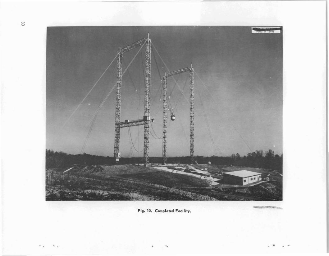
10 12406 Completed Facility March 30, 1954
11 12411 Reactor Shield Tank from Remote March 15, 1954Control Station
12 12412 Reactor Shield Tank and Detector March 15, 1954Compartment Tank - Suspended
13 12415 Typical Lightning Protection - Top March 15, 1954of Tower Leg IV
14 12417 T yp ical Guy Anchor - Completed March 15, 1954
15 12418 View from Top Truss March 15, 1954
16 12423 Typical Tower Base - Leg III March 30, 1954
17 12432 Reactor Shield Tank - Suspended March 15, 1954
18 12433 Reactor Shield Tank Suspended Over March 30, 1954Reactor Tank Pool
19 12532 Aerial View - X-l0 Area in Background March 30, 1954
20 12606 Instrument Console - Control House April 1954
21 12737 Interior of Hoist House May 1954
..

COMPLETION REPORT ON THE TOWER SHIELDING FACILITY
SUMMARY
The Tower Shielding Facility is an experimental installation designed specifically to simu
late special conditions for making shielding studies.
Experiments are to be conducted by mounting a small low-power reactor in a cylindrical steel
tank and installing radiation detection devices in a square steel tank. These tanks will be sus
pended from a ta II structural steel tower approximately 200 ft above ground; the tower is 315 ft
high and consists of four steel columns. The entire structure is stabil ized by guy cables ex
tending diagonally from the top of the tower to guy anchors.
A concrete control house adjacent to the tower structure is located underground to provide
biological shielding for operating personnel. Instrumentation, remote viewing equipment, and
other equipment are located in this building.
A concrete reactor handling pool, a structural steel metal-sided building for housing hoisting
equipment, and hoist control stations are spotted at strategic locations in the immediate tower
area.
All the major structures and equipment items were planned, designed, and constructed to
provide an economical means for obtaining accurate shielding data which are essential to the
development of reactors.
Maps showing locality, topography, site plan, trimetric view, and test boring data are given
in the Appendix. AI so given are photographs showing the various stages of construction progress.
This report is presented chief! y to di scuss the development and construction pha ses of the
project. Reference to operating procedures and detailed descriptions of the reactor and accessory
equipment have been held to a minimum in this report, as they have been discussed in other re·
ports (ORNL-1273, ORNL.1740, ORNL CF-51-11.168, and ORNL CF·53·1.286).
SCOPE OF WORK
In general, the scope of the work required forthis project included the development of the preIiminary design premises, design criteria, definitive design, construction, and installation ofthe faci lity.
The prel iminary design premi ses were estabIished by Oak Ridge Nat iona I Laboratory phy s ic ists and engineers, and through their efforts thefinal design criteria and the definitive designswere evolved. The Oak Ridge National Laboratoryfurnished design criteria for the tower, hoists, andtower foundations; the definitive design for thecontrol house, reactor tank pool, reactor withassociated instrumentation and shield ing, accessroad, and uti lities; procured hoi sts for insta Ilation
by a contractor; fabricated and installed the reactor with associated instrumentation and shielding; and performed miscellaneous work to assistthe contractors in the completion of the faci lity.
The Atomic Energy Commission made arrangements with the U.S. Corps of Engineers to performsite exploration work; awarded contracts for TitlesII and III engineering services for the tower, towerfoundations, and hoists; awarded contracts forthe construction of the tower foundations, controlhouse, hoist house, reactor tank pool, and accessroad; and awarded contracts for the fabricationand erection of the tower structure.
This project is the culmination of considerableexploration into possible methods for establishingreasonably accurate criteria for the des igns of

special shielding. It was concluded that thisfac i Iity wou Id afford the surest, fastest, andcheapest method for conducting full-scale shielding experiments which would provide optimumdesigns for this particular type of shielding. Theinitial test-s wi II be conducted to determine theeffect of radiation leaving a particular side ofthe reactor sh ield. Later tests wi II be performedwith mockup shields to determine the radiationdose in the detector compartment for a simpleshield design.
DESCRIPTION OF WORK
Location
The facility is located on Copper Ridge approximately 2 \ mi les south-southwest of the Oak RidgeNational Laboratory plant area. Tbe nearest inhabited area is approximately 1 mi Ie south andisseparated from the area of the fac i Iity by theClinch River. This site was selected after detai led preliminary investigations, in the generalvicinity, were made to determine the most advantageous location with respect to the surroundingtopographical subsurface condition, accessibility,and nuc lear safety.
General Topography
The facility is located at an elevation of 1066 ftabove sea level on the crest of a knoll wh ichprojects from the south s ide of the main CopperRidge range. The area in general is rugged andis characterized by steep-sided valleys to theeast, southeast, and south. The sides of thevalleys are moderately forested with scrub-oak,pine, and undergrowth, but the crest of the knollis reasonably free of trees and undergrowth. Theterrain surrounding the area varies in elevationfrom about 900 ft in the adjacent valleys to apeak of approximately 800 ft north of the installation, which is at an elevation of 3000 ft abovesea level.
Site Geology
Underlying the site and exposed in the valleyis gray, bedded, massive dolomitic limestone ofthe Knox formation interbedded with conspicuouschert zones. Without prominent faults in thevicinity of the site, this formation attains a thickness of approximately 2600 ft. The soil overlyingthe rock is a reddish silty clay with streaks,layers, and pockets of silty yel,low clay inter-
spersed with fragments of hard angular chertsvarying in size from sand grains to small boulders.
Site Preparation
Field Exploration. Exploration by core dri II ingto determine the depth of satisfactory foundationmaterial and the character of the underlying rockwas performed during November 1952. In one coreboring, rock was found at a depth of 64 ft belowthe surface and was cored to a depth of 76 ft.T his core revealed dark-gray, fine-gra ined limestone interbedded with light-gray Iimestone andchert and ti ghtl y closed, nearl y hori zontal joi ntswith some oxidation. Three other borings varyingin depth from 45 to 60 ft revealed similar subsurface deposits. Data derived from this exploratory work were uti Iized in preparing the finaldesign for the tower foundations.
Access Road. Access to the area was providedby improving approximately 1%mi les of an exi sting road extending from the White Wing Road tothe tower site. The work involved minor relocationof the road to eliminate hazardous curves, clearingand sloping the adjacent banks, widening the road,providing adequate drainage, and applying a 6-in.crushed stone surface.
Grading and Excavation. Rough and finishgrading of the job site, including erosion control,was performed as required during the variousstages of the construction work. Initially, theimmediate site area was rough graded to providethe appropriate elevations and to permit easieraccess for the erection equipment and for thestorage of material s.
Excavation and backfi II ing were requ ired for theplacement of the tower foundations and guyanchors and for the construction of the controlhouse, the reactor tank pool, and the hoi st house.
Fences. The fencing required for this projectconsisted in installing approximately 9400 lin ftof barbed-wire perimeter fencing surrounding thesite on a radius of 3000 ft, clearing the right ofway, and installing approximately 1800 lin ft ofchain-I ink exclus ion fencing on a radius of 600 ft.The installation of the fences and guard posts,including provi sions for Iighting along the exclusion fence, was performed in accordance withAtomic Energy Commission security regulations.
Utilities. Electrical, water, and telephoneservices were extended along a common 50-ft-wide,cleared right of way from the 7500 zone in the
2

X-10 area to the tower site, a distance of approxi
mately 1~ mi les.Electrical services consisted in the installation
of a 13.8-kv transmission line and a 13.8-kv transformer substation at the site with power distribution provisions to the control house, guard post,hoist house, and the exclusion fence lightingcircuit.
Water service was provided by the installationof a 4-in. galvan ized steel water Iine, with accessory equipment, including a concrete surgetank, located at the 1250-ft elevation on CopperRidge at a point approximately 800 ft from thetower site.
The Southern Bell Telephone and TelegraphCompany installed the telephone Iine which extends from the Laboratory area to the tower site.
Structures
T ower Structure. Th is structure cons ists oftwo simi lar steel towers placed 200 ft apart andtied together at the top with prestressed 2-in.-diasteel guy cables. Each tower consists of two9-ft-square lattice columns 315 ft high, joined atthe top with a 9-ft-square lattice truss that spacesthe columns 100 ft apart. The rectang Ie thu sformed, 200 x 100 ft, faces due north and south,with the 200-ft dimension forming the longitudinalaxis of the facility. Beginning at the northwestcorner of this rectangle, the columns are numerically designated, in counterclockwise order,as legs' I, II, III, and IV. An additional 9-ft latticetruss (instrument bridge) was installed 110 ftabove the ground, between legs I and IV, toprovide space for the installation of electronicequipment and a "take-off" point for variouscables extending to the reactor and detector compartment. The structure is braced with 16 guycables (2 in. in diameter) attached to the topcorners of each tower and extending diagonallyto 8 guy anchors. A personnel lift in leg IVaffords access to the instrument bridge and to thetop truss of the north tower section.
The foundations for the four tower legs aresquare reinforced monolithic concrete footingsapproximately 12 ft square by 3 ft thick supportingpiers 6 ft square by 3 ft high. Embedded in eachpier are eight 1-in.-dia anchor bolts and one3-in.-dia anchor pin. All the foundations andpiers are essentially of the same size, exceptfor leg I which was constructed sl ightly largerto compensate fora variation in the foundation.
The eight guy anchors are rectangular blocksof reinforced concrete 20 x 12 x 8 ft thick withtwo 10-in.-wide flange H beams embedded in theb lock for guy cable ties.
Control House. The control house is a rec-tangu lar-shaped, reinforced concrete structure118 x 33 x 11 ~ ft (outside dimensions) with 18-in.th ick walls and roof. The entire bu i Iding issituated underground, and the roof is covered witha minimum of 3~ ft of earth fill. The building islocated on the north side of the tower structure,adjacent to and equidi stant between legs I and IV.Access is gained through two underground passageways: one is an entrance from the north end ofthe building, and the other, which provides accessfrom the working area under the tower, is a rampleading to the southeast corner of the bui Iding.Offices, toi let, and service faci Iities, remotecontrol equipment, instrumentation, remote viewingequipment, and radiation measuring devices area II housed in th is structure.
Hoist. House. This building is situated approximately 200 ft west of the tower structure andhouses four 11,000-lb and two 12,OOO-lb line-pullhoisting units. The bui Iding is a structural-steelframed lean-to type of structure, 135 x 36 x 17 ftaverage height, with corrugated metal siding androof.
Reactor Tank Pool. A reinforced concretehandl ing pool, consisting of two sections, providesshielding during the removal and storage of fuelassemblies. The large section of the pool is 20 ftsquare by 25 ft deep (inside dimensions), and thesmall section is 4 ft wide by 12 ft long by 22 ftdeep (inside dimensions). The pool is locatedon the west side of the rectangular tower plan andbetween legs I and II.
Equipment
Hoists and Rigging. The six lifting hoists,mounted on reinforced concrete bases, are all ofthe single drum, variable speed, sing Ie-wrap typeand have a starting load speed of approximately16 fpm; the maximum safe operating speed is22 fpm. An eddy-current controlled brake and twomagnetic brakes are incorporated in each unit toensure smooth and safe operation. In event of apower fai lure the magnetic brakes automaticallylock the hoist in position and prevent furthermovement unti I the power is restored or unti I thebrakes are released through an emergency d-cpower source. A bank of batteries mounted in the
3

hoist house and interconnected with the control
stations provides the d-c power for remote emer
gency operation.
The sheaves and blocks are heavy-duty pu lIeys
with deep grooves wh ich reduce the poss ib i I ity
of cable hopping. Idlers mounted on reinforced
concrete piers between the hoist house and the
tower reduce the we ight and drag on the ho i st
cables.Positioning Hoist. This equipment, located
approximately 50 ft northeast of the reactor tank
pool, is utilized for changing the distance between
the reactor tank and the detector compartment tank
and prevents the rotation of the two tanks. The
unit, which can be adjusted by hydraulic controls,
exerts a constant I ine pull wh ich may be varied
to a maximum 5000 lb.Hoist Controls. The operation of the six lifting
hoists and the one positioning lioist is performed
remotely from two locations designated as the
"local station" and the "remote station." The
local station is in the ·control house access ramp,
the walls and roof of which afford partial shielding
from radiation. The remote station is located
adjacent to the reactor tank pool, which permits
maximum visibility of the facility while the hoists
are being operated. However, the operation of the
hoists from this station wi II be performed only
when the radioactivity level is within the per
missible exposure limits. The mechanisms for
the I ifting hoi sts are of the lever-arm type, 5-stage
(up-down), remote control switches keyed and
interlocked to prevent the operation of bothstations at the same ti me. Six of these un its,
one for each hoist, were installed at each station.
The positioning hoist motor can be operated by
a hydraul ic lever-arm type of control from either
station; remote operation of this hoist is also
provided inside the control house.
Reactor Shield Tank. The reactor shield tank
was fabricated from ~ -in.-thick boi ler plate shaped
and welded to form a 12-ft-dia by 12~-ft-deep
water-tight vessel with a hemispherical bottom.
Mounted on top of the reactor tank is a structural
frame with flanged wheels attached which ride
on the top rim of the tank. This frame can be
rotated through an ang Ie of 270 deg by means of
a remotely controlled gear train. Two rai Is sup
ported on the frame prov ide a track on wh ich rides
the reactor structure. This track thus permits
the reactor to traverse the diameter of the tank in
all directions.
4
During tests the tank is suspended by a series
of cables and sheaves between legs I and II at
approximately 200 ft above ground level; in this
position the tank will be directly above the reactor
tank pool. At the conclusion of an experiment the
tank can be lowered into the pool for servicing
t he reactor and for chang ing the fue I elements,
or it can be positioned in a supporting frame which
is provided adjacent to the pool.
Detector Compartment Tank. This tank is a
5-ft-square, 7 -ft-deep water-tight vessel fabr icated
from 3~ -in.-th ick boi ler plate except for a panel
approximately 3 x 5 ft in each side and a 3-ft-dia
panel in the bottom, each of which is 1;. in. thick.
Th is change in plate thickness was for tl,e purpose
of reduc ing the sh ielding effect. The tank is
suspended by a cable arrangement s im i lar to that
used for the reactor shield tank. Two remotely
operated gear and screw arrangements mounted
on top of the tank permit pos itioning the detector
both transversely and longitudina Ily with in the
tank.
During tests this tank wi II also be suspended
approximately 200 ft above the ground by means
of four hoisting cables. The position of the tank
may be moved toward legs III and IV or to with in
35 ft of the reactor sh ield tank. At the conc lusion
of an experiment the tank can be lowered to a
concrete pad for servicing.
Li ghtn ing Protection. The entire tower area,
bounded by the guy anchors, is encircled with
a No. 1/0 base copper wire counterpoise buried
approximately 18 in. below grade. Copper-clad
ground rods were driven at each tower leg footing,at each guy anchor, and at intermediate points
around the perimeter of the counterpoise. Four
major cross connections, also of buried No. 1/0bare copper wire, with ground rods driven at
intervals, were installed at approximate right
ang les to the perimeter counterpoi se and cross
at about the center of the tower working area.
The entire grounding system and the grounding
connections to all equipment, hoists, electrical
items, etc., are connected to the water supply line.
Field measurements establ ished the soi I resi s
tivity in the grounding area as 1800 ohm-ft. Based
on these measurements the resistance to the
ground of the entire system will not be more than
1 to 3 ohms.
Capacitors and I ightning arresters at all motor
term ina Is protect the equ i pment from abnorma I
electrical surges.
"

•Instrumentation. The instrumentation for radi-
ation measurements and the remote control mechanisms for operating the reactor and the detectorin the tanks are located in the control house.This equipment is, basically, commercially avail
able recording equipment and electronic data collecting devices that have been utilized as builtor altered to the Laboratory's specifications.Special-purpose devices were fabricated to performspecific functions as dictated by the unique operating requirements of the facility.
Flexible cable leads were suspended from thereactor shield tank and the detector compartmenttank to the instrument bridge.
DESIGN PREMISES
Tower Foundations
The unit pressure on the footings for the towerfoundations was fixed initially at 2 tons per squarefoot. The resistance to penetration of soilsamples indicated that the compressive strengthof the soi I was about 3 tons per square foot.Based on Terzaghi's formula for ultimate bearingcapacity of shallow square footings, the ultimatebearing capac ity was found to be 11.4 tons persquare foot. With a factor of 3 appl ied for safety,the resistance to penetration was computed to be3.8 tons per square foot.
On the basis of data obtained from the soi Isamples which were tested by the U.S. EngineeringDepartment Soi I Testing Laboratory, the towerfoundations were des igned for 1.9 tons per squarefoot loading with a maximum allowable differentialsettlement of 1 in. The allowance of 3 for a safetyfactor was used in computing the required values.
Tower Structure
The bas ic data for further stud ies and des ignof the facility were presented in "Tower ShieldingFacility - Design Criteria," prepared and compiled by the Oak Ridge National Laboratory.
General designs and cost comparisons indicatedthat, of the semirigid structures that were investigated, one with longitudinal cable ties and pinnedtransverse trusses in the end bents offered thegreatest opportunity for bas ic economy of structure, consistent with structural stability andsafety, reasonable erection, and pos itioning ofloads by the use of suitable hoisting and riggingprocedures.
The recommended structure was developed onthe basic concepts that:
1. there would be no structural framing or members,except Iifting and guy cables, with in a distanceof 100 ft of either the reactor shield tank orthe detector compartment tank;
2. the support for the two loads wou Id be "openended" - that is, there should be no structuralframing beyond either tank in the Iine of actionbetween them.
The guyed and braced design was therefore developed in complete detai I in order to establ ishits essential validity, economy, and feasibility.The prestressed 2-in. cables were designed tocarry loads of 40,000 and 76,000 Ib in horizontalties and inclined guys, respectively.
Live and Wind Loads. For the structural design,the following basic live loading conditions wereestab Iished:
Case IDead 10<;Jd + live load + 20% impact (on 55-ton
or 30- and 40-ton loads).Case II
Dead load + 30 Ib/ft 2; wind on 1~ times pro
jected area of members, with no suspended loads.Case III
Dead load + live load + 20 Ib/ft 2 ; wind on 1~ti mes projected area of members and exposed areasof suspended loads.Case IV
Dead load + live load + 0.05 seismic force.
The relationship between wind loads, as above,and the corresponding wind velocities is asfollows:
30-lb wind equivalent to 105 mph20-lb wind equivalent to 80 mph2-lb wind equivalent to 25 mph
F rom a study of the Knoxv ilie and Oak Ridgeclimatological records, it was established that themaximum wind of record was 71 mph (based on thefastest mile and a recorded period of 40 years).The average daily wind velocity for the year 1951was 9.7 mph, corresponding to a wind load of0.3 Ib/ft2 • The maximum of 71 mph occurred inApri I 1944; other maximums occurred as follows:1947, 61 mph; 1948, 68 mph; 1951, 57 mph. TheLaboratory agreed that operation of the TowerShielding Facility will be prohibited during windvelocities exceeding 20 mph (= 1.3 Ib/ft2 ).
Types of Steel. In the preliminary studies, aswell as in the recommended design, it was assumed that A7 carbon steel would be used for the
5

5.65.41.20.88
13.08
structura I members of the tower. We Ided construction was developed for the legs, trusses, andbracing members of the recommended design, withthe field connections between sections of thelegs and between legs and trusses, etc., beingmade with high strength bolts. For shipping anderection purposes, the tower legs were fabricatedin sections of length (9 x 9 x 45 ft) that cou Idconveniently be accommodated in a 50-ft openfreight car or in a truck trailer.
In the earlier designs, in which the unit stressconsideration was vital in the choice of the mainsections, the use of A94 structural silicon steelwas considered for the main material of themembers. It was found that the resulting savingin total weight of structural metal and in construction cost would be reduced by the higherun it price required for the silicon steel. AI so,it would not have been poss ible to have a fu lIywelded design, since the silicon alloy is notreadi Iy weldable; and with a combination of rivetedand welded fabrication, the weight of detail material at joints, etc., would have been increased.
While the use of the silicon material might havereduced the mass of the recommended structuresomewhat and thus slight Iy have reduced thebackground scattering, the uncertainties outlinedabove and the doubt as to any real economy inthe fabrication and cost led to the final decisionto use conventional A7 carbon steel in the design.
Scattering Effects. The effect of backgroundscattering was one which received considerablestudy during the design period. Several of thestructural designs proposed for the tower, whichineluded overhead truss systems, had to be rejected because of the excessive percentage ofbackground scatteri ng.
The approximate and exact formulas for background scattering were derived by Oak RidgeNational Laboratory physicists. It was alsoestablished that a reasonable limit for the totaleffect would be approximately 15%; designs andgeometry were I imited by th is factor (see reportORNL-1273, issued Oct. 15, 1952).
Based upon the formulas, the per cent of background scattering for the recommended design wascalculated as follows:
Front tower legs, two at 2.8%Rear tower legs, two at 2.7%Upper end trusses, two at 0.60%Instrumentation platform
6
Hoists and Rigging
The magnitude of the lifted objects, the types ofmovement, the limitations on relative displacementand rotation of the objects, the positioning ofobjects with respect to each other and to elevation, the effect of rigging on scattering allinfluenced the proposed des ign of the hoi sts andthe rigging. Such basic consideration, with flexibility for future loading and simplicity of operation, was satisfied in the proposed design whichevolved from consideration of many methods ofsupporting the objects and rigging.
With the use of the recommended system offraming, the hoist capacities depend upon theangle between the operating cables and the towerlegs. An increase in the tower height would resultina more costly tower structure, but the cost ofthe hoists would be reduced. Cost comparisonswere made to secure the Ieast expens ive comb ination of hoist and tower.
A model built by Oak Ridge National Laboratorystaff members, to a scale of approximately1 in. = 40 ft, aided Oak Ridge National Laboratoryand Knappen-Ti ppetts-Abbett-McCarthy personnelin studying the rigging and guying problems.
As finally adopted, the location of the hoistingsheaves on the tower and the inclusion of aconstant tension positioning hoi st operating a linebetween the reactor shield tank and the detectorcompartment tank provide a smooth operating arrangement for positioning both horizontally andvertically and, furthermore, prevents the rotationof the two tanks with respect to each other. Thusthe arrangement as finally adopted provides a mostsatisfactory alternate to the rigid structure whichhad been given earl ier cons ideration.
Control House
The design of the control house was developedto adhere to specific requirements for shielding theoperating personnel. The known potential radiations emitted from the reactor governed theshielding requirements, and the location of thebui Idin g, with respect to the di stance from thereactor, governed the quanti ti es of shi elding materials required. After the location for the buildingwas establ ished, it was decided to con struct itunderground, which would minimize the shieldingrequirements by utilizing earth fill as a partialshielding medium. This arrangement effected aconsiderable saving in construction costs by
•

• eliminating the necessity of providing thicker wallsfor an above-the-ground structure.
Reactor Tank Pool
The design of th e reactor tank pool was al sodeveloped to meet specific requirements for radiation shield ing. The pool was made Iarge enoughfor the tank to be covered with a minimum of 8 ftof water. Removal of the fuel assemblies will bedone under water, and they will be stored in racksin the small section of the pool. Remova I of thereactor from the reactor shield tank and moving itinto the small section of the pool will be accompli shed by means of a loading gantry mountedon rails along the top edge of the small section ofthe pool.
PARTICIPANTS
The participants in the project and a briefdescription of their functions are given below.
U. S. Atomic Energy Commission
Oak Ridge Operations OfficeOak Ridge, Tennessee
Oak Ridge National Laboratory, operated byCarbide and Carbon Chemicals CompanyA Division of Union Carbide and CarbonCorporation
P. O. Box POak Ridge, TennesseeOperated under contract W-7405-eng-26, Mod. 33.
Knappen-Tippetts-A bbett-McCarth y(arch i tect-eng ineer)
62 West 47th StreetNew York 36, New YorkAEC fixed-price prime contract
No. AT-(40-1 )-1528
Chari es Hobson Company, Inc.(construction contractor)
2923 Sutherland Avenue, NWKnoxville, TennesseeAEC fixed-price prime contract
No. AT-(40-1)-1381
Karl Koch Erecting Company, Inc.(construction contractor)
362 Casanova StreetBronx 59, New YorkAEC cost-plus-fixed-fee prime
contract No. AT-(40-1 ).1382
Whiting Corporation (equipment fabricators)Harvey, III ino isORNL fixed-price purchase requisition
No. W36X-14855
Atomic Energy Commission
In accordance with their respon si bil ities withregard to the administration of lump-sum and/orfixed-fee prime contracts, the Oak Ridge OperationsOffice of the Atomic Energy Commission performedthe following work:1. made all arrangements with the U. S. Corps of
Engineers for the site exploration work, including core dri II ing and testing of the soi Isamples,
2. reviewed all preli minary and final drawings andspeci fi cations,
3. performed .all work leading to the selection ofthe architect-engineer and the constructioncontractors,
4. maintained Iiai son between the Laboratory and
the pri me contractors,5. fum ished general supervi sion of the contracts
and participated in the final inspections of thecompleted facility.
Oak Ridge National Laboratory
The Oak Ridge National Laboratory's participation in this project consisted in the followingservi ces:1. preparation and submission of the preliminary
proposal, which outlined the entire scope andestimated cost of the project,
2. development of the des ign criteria for the towerfoundations, the tower structure, and the hoi sting equipment,
3. design, fabrication, and installation of thereactor shield tank and the detector compartment tank and associated equipment, includingthe reactor and control s,
4. preparation of working drawings and specifications on the control house, reactor tank pool,access road, util ities, and grounding system,
5. initiation of requisitions for the purchase of thehoisting equipment, the details of which werehandled by the Carbide Purchasing Department,
6. provls Ion of engineeri ng services for theinspection of the control house, reactor tankpool, access road, and the util ities,
7

7. collection of data and preparation of th is compi eti on report.
Knappen-Ti ppetts-Abbett-McCarthy
The responsibilities of Knappen- Tippetts-AbbettMcCarthy in connection with the completion of thefacility consisted in the following:1. preparing the final design drawings and specifi
cations for the tower structure, the tower foundations, and the hoisting equipment from criteriafurnished by the Laboratory,
2. furnishing a field representative to maintainI iai son with the Karl Koch Erecting Companyand the Laboratory.
Charles Hobson Company
The Charles Hobson Company performed all workrelated to the site preparation, wh ich cons isted ofthe following items:1. grading at the site,2. access road,3. all foundations,4. reactor tank pool,5. underground control house,6. utilitIes, including guard houses and fences,7. grounding system.
Karl Koch Erecti ng Company
The Karl Koch Erecting Company, in accordancewith definitive design and specifications furnishedby Knappen-Tippetts-Abbett-McCarthy, performedthe following work:1. erected the tower columns and installed the
guy cables,2. installed the lightning protection system,3. installed the hoists,4. erected the hoi st house,5. installed the hoist controls and rigging for the
hoist cables,6. insta II ed the personnel lift,7. install ed all electrical servi ces located above
th e tower footi ngs.
CONSTRUCTION METHODS AND EQUIPMENT
Charles Hobson Company
Earth moving pans, bulldozers, and graders wereutil ized in the grading of the access road, andsheep's-foot rollers were employed to obtain theproper compaction.
The trench for the water line to the site wasexcavated with a trenching machine; a bulldozer
8
was uti! ized for general level ing in advance ofthe trencher and for backfi II ing.
Power shovels with backhoe attachments, earthmoving pans, and bulldozers were employed for thesite excavation. Sheep' s-foot rollers and pneumatictampers were used for placing earth fi II and forbackfilling; a sprinkler truck was used in obtainingthe correct moi sture content.
Concrete forms were ma inl y of the prefabricatedpanel type; however, where conditions dictatedtheir economy or convenience, bu il t-in-place formswere used.
During the early part of the construction, concrete was del ivered to the site in ready-mix trucks.However, difficulties developing from their deliverymade it necessary for the contractor to use a smallportable mixing pi ant for the remainder of the work.Chutes, wheelbarrows, and concrete buggies wereused to place the concrete. Gas-engine-poweredvibrators were util ized to assist in placing theconcrete and to obtain void-free concrete.
Karl Koch Erecting Company
To faci! itate handling, loading, and erection, the9-ft-square tower legs were shop fabricated insections 45 ft long, and the three 100-ft-longtrusses were each fabri cated in two sections. Themajor portion of these sections was transporteddirectly to the site by motor truck trai lers. However, because labor troubles delayed the truckshipments, a few sections of the tower were shippedby rail to Oak Ridge, unloaded at the rail sidingwith a motor crane, and trucked to the site.
A crawler crane equipped with a 100-ft boom wasused to unload and to handle the sections at thesite and to erect the lower two secti ons of eachtower leg.
The tower legs were erected in pairs (legs II andIII together and then legs I and IV). After the twolower sections had been erected, a twin-boomderrick was mounted at the top of each leg. Thederrick and a multiple-drum hoist, anchored nearthe base of each leg, were used to hoist the next45-ft section of each tower leg into position. Aseach succeeding section was secured in place withfield erection bolts, the erection derricks, by meansof rigging powered by a second multiple-drumhoist, were hoi sted to the top of the structure.Temporary guy cables to support the legs weremoved up as each section was erected. When thederricks reached the top of the respective pair of
;

legs, the truss that connected the pair of legs,
which had previously been assembled on the ground
di recti y below its 'fi nal posi tion, was hoi sted into
position by the derricks.
The permanent guy cables were placed in position
as soon as possible following each stage of the
erection.
(Note: As a result of the well-designed erection
equipment, the excel Ient planning and schedul ing
of the work, and the expeditious handl ing of the
field erection, the entire construction problem was
handled in an exemplary manner.)
Oak Ridge National Laboratory
The hemispherical bottom reactor tank was fabri
cated at an outside shop and then shipped to Oak
Ridge National Laboratory. The rotati ng spider
frame work, the movable carri age that supported
the reactor, and the reactor and reactor controls
were all fabricated in the Laboratory shops; these
items of equipment were assembled and were in
stalled in position on the reactor tank and then
subjected to test operations in the shop. When
the tower and hoisting equipment had been com
pleted, the entire assembly was transported to the
site on a low wheel trailer.
The detector compartment tank was fabricated in
the Laboratory's shop, as was the associated gear
and screw positioning mechanism. As with the
reactor and reactor tank, the detector compartment
tank and the associated equipment were assembled
and test operated in the shop before being trans
ported to the site. As many of the electronic
controls and as much of the instrumentation equip
ment as possible were procured from commercial
sources. However, because of the unique requ ire
ments of the faci Ii ty, it was necessary to modify
many of the commercial items and to design and
fabricate in Oak Ridge National Laboratory shops
many special ized instruments. To as great an
extent as possible these items and instrumentswere assembled and tested in advance of the in
stallation in control house at the tower site.
The procurement and the delivery of the hoists
were handled directly by Oak Ridge National Labo
ratory; however, the installation was performed by
the tower erection contractor under the supervision
of a n erection engineer from the Wh iting Corpo
ration, the hoist fabricators. The unusual size of
the hoist drums presented some difficulties in
locating machine tool s large enough to handle
those parts; there were a Iso some difficulties
experienced in the procurement of satisfactory
electrical controls from the General Electric
Company. These slight difficulties resulted in a
delay in del ivery.
The planning and scheduling of the Laboratory's
participation to permit the fabrication, assembly,
and testi ng of the reactor, detector compartment,
and instrumentation to proceed concurrentl y with
the field construction of the ~acility reduced to the
lowest minimum the period required for the field
installation of the items furnished by the Labo
ratory. This resulted in the utilization of the
facility at a much earlier date than would have
been otherwise poss ibl e.
APPRAISAL OF CONSTRUCTION
CONTRACTORS'WORK
Charles Hobson Company
The qual ity of the work performed by the Hobson
forces was genera II y very good. In some in stances,
however, it was necessary for this contractor to
discuss with some of his subcontractors the quality
of their work; then good results were usually ef
fected without delay. His rate of progress was
also good, and, except when slow deliveries of
materials hindered, all phases of work were finished
on time. Hobson's cooperation was excellent,
especially in deal ing with Koch in that company's
concurrent erection operations; all their mutual
"problems" were examined carefully, and with
considerable discretion, before any action was
taken, and the problems were solved to their mutual
sati s fact ion.
Karl Koch Erecting Company
The quality of the work by Koch was excellent;this rather unusual job of erection was handled
with dispatch and facility. The rate of progress
was far ahead of schedule throughout, except as
dela yed by slow del iveries of hoi sts and by later
modifications in connection with electrical work.
Cooperation in connection with Hobson's con
current work was excellent; there were no oc
casions when problems in connection with their
overlapping interests were not coordinated with
good resul ts. The supervi s ion throughout was well
handled.
9

OUTLINE OF RECORD OF WORK PROGRESS
The work progress is given below:
RECORD OF UNUSUAL CONDITIONS
Charles Hobson Company
The time lost during the construction period as aresul t of strikes is given below:
Inclement weather caused only two days ofworking time to be lost prior to December 16,1953; from that date unti I the completion of theproject, however, there were several days at intermittent intervals when it was necessary to halt orto interrupt work on certain phases of the project.
General strike, all construction suspended
On December 14, 1953, a transformer in the substation at the facility exploded. The delay inreplacing electrical service to the project resultedin one day of lost time for all construction.
The extremely dry weather made it necessary toadvance the schedule for the installation of thewater Iine to the site so that water would be available for provid ing the proper moisture content forthe earth backfilling operation.
The unusual experimental and developmentalnature of the project and the fact that the designof the reactor, detector compartment, and relatedin strumentation was in progress during the constru ction of the tower, control house, and otherfield work made it necessary to make severaldesign changes, particularly on the electricalinstallation. As a result, there were some delaysand some interruptions; however, by adjusting thework schedule to meet the demands of thesechanges, the contractor was able to meet theestablished completion date.
Karl Koch Erecting Company
During the construction period it was necessaryto make adjustments to work schedules to compensate for interruptions caused by strikes andweather conditions. However, by efficient planning,the contractor was able to complete the work within the establ ished time.
Labor difficulties at the Truitt ManufacturingPlant in North Carol ina caused a three-day delayin the shipping schedule.
Labor trouble at the truck transport companiesmade it necessary for some of the units to beshipped by rail to Oak Ridge, where they wereloaded on trucks and hauled to the job site. Th isarrangement resulted in some delays.
Only two days of working time were lost becauseof inclement weather between July 31,1953 and thestructural completion of the tower on Nov. 23, 1953.
Whiting Corporation
An order for the hoisting equipment was placedwith the Whiting Corporation on March 18, 1953and specified that delivery be made by October1953. However, material procurement difficultiesdelayed the delivery of the major items untilDecember 1953.
Field tests on the complete hoist installationwere made on February 10, 1954. These testsrevea led that mod ifications to the electri cal
Nov. 4, 1953Feb. 20, 1954
July 31,1953Feb. 20, 1954
March 27, 1953Jan. 15, 1954Feb. 5, 1954
Oct. 10, 1952
July 1952
Because ofa strike inthe X-10 Area of OakRidge National Laboratory, electri cians andpipefitters did not report for work
Because of a strike ofsheetmetal workers atK-33, the electri cians,pip efi tters, and sheetmetal workers did notreport for work
Whiting Corporation
Start (on job)Complete
Oak Ridge National Laboratorydesign
Start
Knappen-Tippetts-A bbettMcCarthy design
Start
Charles Hobson Company
StartPartial acceptanceComplete
Karl Koch Erecting Company
StartComplete
November 9, 1953 toNovember 16, 1953
Ma y 1, 1953 toMay 20, 1953
July 27, 1953 toJuly 30, 1953
10

",
..
control s were requ ired to incorporate features toeffect greater operating flexi bil ity. The modifications to the controls were completed in June
1954.DISPOSAL OF JOB RECORDS
The disposition of the job records is given below.1. Prints of contract drawings, specifications,
and the original tracings are filed in a vault inthe Design Engineering Department at Oak RidgeNational Laboratory.
2. Copies of equipment catalogs and manualsare filed at the tower site, in the Mechanical Department office and in the Engineering Department.
3. Guarantees are filed in the Engineering andMechanical Division office at Oak Ridge NationalLaboratory.
4. Sti II photographs of construction progressare on fi Ie in the Laboratory Records Departmentat the Oak Ridge National Laboratory.
5. A motion picture film depicting phases ofconstruction is on file in the Laboratory RecordsDepartment at Oak Ridge National Laboratory.
PROJECT COST SUMMARY
A summary of the project cost is presented as
follows:
Participant
Engineering and Inspection
Atomic Energy Commission siteinvestigation
Oa k Ridge National La boratory
Knappen-Tippetts-A bbettMcCarthy
Total
Procurement and Construction
Charles Hobson Company
Karl Koch Erecting Company
Oak Ridge National La boratory(Wh iting)
Oak Ridge National Laboratory(fabrication and installation)
Total
Grand Total
Authorized Project Funds,
Atomic Energy CommissionDirective
Cost
$ 5,155.00
204,217.00
106,250.00
$315,622.00
$ 508,624.72
527,817.00
248,550.00
397,000.00
$1,681,991.72
$1,997,613.72
$2,000,000.00
11

•
•

,.

•
APPENDIX
13

SCALE IN MILES
o 2000 4000 6000 BODO 10000h _ I
SCALE IN FEET
GD
o
R
Louisville 0.(16
T Yc
Ao
--.. ~~,.......'~ '\
,. --------'.--,' ............._------- '.\,'\
ELlA ENTRANCE
! MIS SIS SIP P I {
I !I ._- n------l----
LOCALITY MAPo 40 SO 120
........ eM
RESERVATIO~ BOUNOARY~ / __I- '""V'1..-~___.---/-.~._-J--------"../--/""" I .-.........••__
OLIVE R SPRING';;ENTRANCE
OFFICIAL USE ONLYF -II 082
Map A - Locality of Tower Shielding Facility Site Placement in Oak Ridge Area.
15

•
•

:..
o~
1200
J2400 3600 4800
I
C -11083
SCALE IN FEET
Map B - Area Topography of Adjacent Related Features.
17

'0-.
N
.o
·fj
--f;} ir-D~-\\'\u_'
--~:l ~ ~ ~
It:=:t=:t=~~ ~~RAMP~~==t=;-~~~\J
oo
1055
~_~_I060
(
40 80 120........ IiiiiiiiiI IiiiiiiiiI
SCALE IN FEET
..
.'
18
c- 11084 r
Map C - Site Plan of General Placement of Elements.

..
C - 11085
LIGHTNING PROTECTION>~
GUY ANCHOR
Mop D - Trimetric View of General Placement in Three Dimensions.
19

Finished~
Depth
Ft.
BORING B
N 10,181.5£ 29,412.0£1. 1075.9
Reddish brown sandy CLAY, moisl, liard,moderolely collesive; rocff fragments(cller/)
Reddish brown silty CLAY, moist,collesive, hard; rocff fragments(cherO in lorge amount.
I>- Reddlsll brawn lean CL A Y, hord, Samechert fragments and occaSionalboulder, jOints, fissures ond intrusions of yellow clay
Dorff grey, fine grained LIMESTONE,occasionally interbedded with lightgrey IimestonfJ and chert, light, clased,nearly horizontal jOints with 'lomeoxidation
Bottom of borlf/g
BORING B3
N ",001.1£ 29~ 409. 1£1. 1068.6
Reddish brown silly CLAY, rock(ell;}rt) fragmen/s, hard, moisl
Reddish brOWin CL A Y, trace silt,hord moist, rock (cherO frogments,join/s, fissures
Reddisll brown, silly CLAY, hard, moist,rock (cherf) fragmen/s, joinls, fissures,intrllslons of y(Jllow clay
!feddisll brown CLAY, troce s//1,hard, wet, rock frogmenls, occasionalboulder, jain/s, fissures, Intrusionsof yellow cloy.
BOffOm of bOrln
~IO
Finished I
~t
loePth1Ft
60
BORING B 2
N 11.001.0£ 29,288.4£1 1060. 6
Reddish bra Win SILT ond CL AY, hard,rock (cherf) frogments, moist
. .
A Rfiddlsh brown CLAY, hord, somesmall rock (chert) fragments,occasional boulder, wet, joints,fissures and intrusions of yeltowcloy,
Boflom of borln
BORING B 4
N 10,183.1E 29,291.7EI, 1070.0
Reddish brown, silty CLAY, hard, somerock (cherf) fragments, occasionalboulder, joints, fissures, intrusionsof yellow cloy.
Reddish brown CLAY, !lard, wet,some rock fragmenls, OCcasionalboulder, jolnls, fissures, in/ruS/OIISI)f yellow cloy
•
LEGEND
ROCK
FRAGMENTS
SAND
IWATERLEVEL 51L T
..DATUM IS MEAN SEA LEVEL
20
Map E - Test Boring Data.

•
•
• • •
UNCLAUII'Il!DPHOTO 11061
•
Fig, 1. Construction Progress.

UNCLASSIFIEDPHOTO 111)61
Fig. 2. Typical Foundation Uncl.r Construction.
• '. •

Fig. 3. Typical Guy Anchor Under Construction.
• • • •

24
Fig. .c. R~octo, Tank Pool Befor. Backfill.
•
•
,
•

• •
Fig. S. Construction Progrus.

•
Fig. 6. Regctor Tonk Pool, Leg I Bose and Control House.
26
•
•

••
PHOTO 11161& ?P
Fig_ 7. Construction ProSIren.
•

a
Fig. 8. Construction Progress.
• PHOTO mil
•
"
• •

•
Fig. 9. Construction Progress.
•
wo
Fig. 10. Compl.t.d Facility,
••

•
•
.·
Fig. 11. Reocto, Shield Tonk from Remote Control Station.
P'!U-0 lUll
31

32
Fig. 12. RflJctor Shield Tonk and Detector Compartment Tonk _ $ulpend.d.
:
•
•

• • •• • •
ww
Fig. 13. Typicul Lightning Protection - Top of Towe, Leg IV.

34
Fig. 1.4. Typical Guy Anchor - Campl.teeL
••
•
/

•
•
• Top Truss.. 15 Vie" homFIg. •
35

36
Fig. 16. Typical Towe, Base - Leg III.
•
•
I
••

• . ' . , • •
Fig. 17. Reactor Shl.ld Tank - Suspended.
•

wm
•
• • •
Fig, 18. Reactor Shield Tank Suspended Over R.actor Tonk Pool. .-
•

•
• Pli 8lim
•
Fig. 19.....rlol View - X·I0 Areo in Bockground.

Fig. 20. Instrument Console - Control House.


••
•
•
•."