complex engineered systems design verification based on ... fileaware of any assumption-guarantee...
TRANSCRIPT

Complex Engineered Systems DesignVerification Based on Assume-Guarantee
Reasoning
Hoda MehrpouyanTSYS School of Computer Science
Columbus State UniversityColumbus, GA
31909, USA
Dimitra Giannakopoulou, Guillaume BratNASA Ames Research Center
Moffett Field, CA94035, USA
Irem Y. Tumer, Chris HoyleComplex Engineered Systems Design Lab
School of Mechanical, Industrial,and Manufacturing Engineering
Oregon State UniversityCorvallis, OR, USA
Abstract – System verification is one of the most criticaltasks into the process of engineered system design. This pro-cess is time consuming and prone with errors when a limitedset of scenarios is evaluated to guarantee the correct func-tionality of the system. Therefore, novel design approachesand tools based on a rigorous framework for analysis, veri-fication, and testing are very much needed. This paper pro-vides such a framework where system properties are verifiedand modeled with respect to the assumptions on the envi-ronment where components and (sub)systems’ performancesare guaranteed under these assumptions. To validate the pro-posed approach, this paper provides a case study to demon-strate how the proposed methodology reduces design com-plexity and presents a formal argument to assess the qualityof the design.
1 IntroductionWith increasing complexity in the design of complex en-
gineered systems such as aerospace, maritime, nuclear, andmajor civil infrastructure systems, the cost and time requiredfor design and development are growing at an unsustainablerate. For instance, Boeing and Airbus experienced signifi-cant delays and cost overruns in delivering their latest 787Dreamliner jet and A380 superjumbo projects [1]. Designflaws were cited as basic issues in the A380 design and pro-duction, which resulted in a variety of glitches such as en-gine blow-up, failure of the backup brakes, and discovery ofcracks on the wings of the planes. Boeing 787 Dreamlinerfaced similar issues, as described in the national transporta-tion safety board reports of the fire incident in the auxiliary
power unit (APU) on a Japan Airlines 787 flight from Bostonon Jan. 2013. The report concluded that a design flaw mightbe the root cause of the fire. In another case, a Japan AirlineDreamliner flight from Boston faced a considerable delay af-ter a fuel leak resulting from a faulty valve. The design flawsand equipment malfunction cost $5 Billion for Boeing on topof the $1 Billion compensation claim from airlines, such asUnited Airlines and Air India.
The design complexity of these types of safety-criticalsystems present various challenges for their safety assess-ment process. In order to improve the design and develop-ment process, manufacturing companies are increasingly re-lying on simulations to understand the unexpected behaviorof the design to improve both robustness and performanceof system [2]. Based on his research, Foster [3] concludedthat verification process (i.e., establishing that the design, ifimplemented, would provide the desired functionality) con-sumes over 60% of the design time. In addition to longer ver-ification time which results in project cost increase, a surveyconducted by Collett International Research Inc. [4] revealedthat while the traditional verification approaches, i.e. Pre-liminary Hazard Analysis (PHA), Failure Mode and EffectAnalysis (FMEA), are still applicable, they are not sufficient;that is, they do not take into the consideration the whole com-plex network of relationships, between events, components,and the environments where the components operate in.
Therefore, the aim of this paper is to provide a frame-work for the effective use of formal methods in the earlyverification of safety requirements in safety critical systems.

The proposed framework allows for automatic generation offault trees, and exhaustive safety property verification withthe help of model checking algorithms. The approach isbased on assume-guarantee compositional reasoning whichverifies global safety properties of the system by verifyinglocal properties of each component [5–8]. Therefore, theverification of large systems is made possible through theverification of each system components separately, while us-ing assumptions about each components environment. Whilecompositional reasoning based on assumptions and guaran-tees is popular in other domains (see, e.g, [9–11]), we are notaware of any assumption-guarantee style reasoning to verifythe safety properties of complex engineered systems.
The remainder of this paper is structured as follows:Section 2 presents the background and related research onfailure analysis techniques in the early stages of system de-sign, while discussing their strengths and weaknesses. In ad-dition, the definition of assume-guarantee reasoning and itscommonly used terminologies and operators are addressed inSection 2. In Section 3, an overview of the step-by-step im-plementation of the assume-guarantee reasoning algorithmon the components of the design architectures is explained.Section 4 outlines the application of the proposed methodol-ogy in the analysis and verification of the safety properties ofthe satellite electrical power system design. The paper endswith conclusions and future work.
2 BackgroundA variety of modeling approaches and tools are used in
industry or in academia, e.g., AADL [12], Modelica [13],Ptolemy [14], MATLAB/Simulink [15], SysML [16]. Thesetools are used to model the functionality and architecture ofthe system design, then simulation is carried out to verifythe design. However, most of the simulation experimentsare designed to evaluate a limited set of scenarios in orderto deal with the system complexity. The effects of this in-formal and incomplete verification is the possibility that anon-tested scenario could result in unexpected behavior andcatastrophic system failure. To address the incomplete veri-fication of designs via simulation, formal methods have beenproposed to increase the confidence level. Formal verifica-tion enables the evaluation of safety properties at differentlevels of abstractions,( i.e., component, sub-system, system),guaranteeing the systems’ behavior in every possible sce-nario. It is important to note that even formal verificationis as good as the abstract models and properties that one ver-ifies on such models.
One of the objectives of the verification process is tomake sure that the design complies with safety requirements.In order to satisfy most regulatory guidelines and safety stan-dards, designers must develop a safety case to prove thesafety justification of a design. These cases should repre-sent all potential hazards and appropriate steps be taken torectify the situation. These types of safety documents usu-ally include safety specifications, results of failure and riskanalysis, verification approach, and results of all the verifi-cation activities. Figure 1 depicts the general view of theverification process.
Fig. 1: Verification Process in Engineered System Design.
2.1 Design Tools For Safety and Reliability AnalysisThis section provides a review of the scope and limita-
tion of currently available system safety and reliability toolswith respect to verification of complex system designs. Oneof these methods is the risk assessment matrix [17] whichcategorizes risks in the form of probability and severity (lossof function per unit time). In this approach a matrix basedon the importance of severity versus the probability of fail-ure occurrence is created. However, one limitation of thismethod is its lack of ability to identify failure and its prop-agation path. Another initial reliability study is possiblethrough the use of Preliminary Hazard Analysis (PHA) [18]which identifies and provides a database of failures and fail-ure propagation paths. PHA uses risk assessment matrix toassess the risk of each identified failure. The limitation ofPHA is its lack of ability to evaluate risks of aggregated haz-ards or simultaneous design failure modes. In addition, therisk analysis of a complex system design will result in largeand costly implementation. Failure Mode and Effect Anal-ysis (FMEA) [19] is a bottom up approach that investigatesfailure modes of components and their effects on the rest ofthe system. FMEA provides an exhaustive analysis to iden-tify the single point of failures and their effects on the restof the system. The result of the analysis is used to increasereliability, incorporate mitigation into the design, and opti-mize the design. The result of FMEA analysis can be addedto the PHA analysis of the design, since every failure modeof each component is evaluated and additional informationabout the hazards resulting from the failures is obtained.However, FMEA is very costly in terms of resources, par-ticularly when implemented at the component level withincomplex systems. Also, occurrences of simultaneous failuresand multiple faults is not evaluated [20, 21]. The complete-ness and correctness of the analysis is very much dependenton the expert knowledge.
The next group of reliability analysis methods is basedon the symbolic logic of the conceptual models of failurescenarios within a design. The goal is to assess the prob-ability of failure occurrence in the system design. One ofthese methods is the Reliability Block Diagram (RBD) [22],which divides the system into elements based on the func-tional model of the system design, where each system ele-ment is assigned a reliability factor. Then a block diagram of

the elements in a parallel, series, or the combination of paral-lel and series is constructed. Each block represents a functionor an event in the system and each element’s failure mode isassumed independent from the rest of the system. The reli-ability factor may or may not be available for all the systemdesign elements and should be assigned by an expert whichmake it subjective and hard to validate. Another symboliclogic model is based on the Fault Tree Analysis (FTA) [23]which studies the failure propagation path from the point ofstart to the vulnerable components and assigns a severity fac-tor to each failure model. One of the benefits of using FTAis its ability to analyze the probability of simultaneous oc-currence of failure within a complex systems. On the otherhand, the correct probabilistic evaluation requires significantamount of resources.
These traditional safety and reliability tools require de-tail information about components, their failure modes andprobability of failures in order to complete their analysis. Onthe other hand, conceptual design is a process of develop-ing behaviors and functions to create a design solution thatmeets the design requirements. At this early stage of de-sign, specific components have not yet been fully specified,therefore collecting data on failure probabilities of the com-ponents and how they propagate through the system modelis very challenging. The aim of this research is to provide anearly design framework that is able to automatically analyzethe system architecture and verify its capability of meetingthe requirements using abstract design information.
In addition, the traditional methodologies are mostlybased on the evolution of the system through time, given aninitial event and a set of forcing functions. These physics-based models are based on the laws of physics from the out-set. However, mathematical modeling of complex systemsmay not be feasible since changes in operating conditionsand structural dynamics can affect the mathematical model,and it makes it difficult or even impossible to develop mathe-matical models for all real-life conditions. Therefore, thisresearch takes advantage of automata learning and modelchecking approaches. Model checking is one of the ap-proaches to formal verification of finite state hardware andsoftware systems [24, 25]. In this approach, a design will bemodeled as a state transition system with a finite number ofstates and a set of transitions. The design model is in essencea finite-state machine, and the fact that it is finite makes itpossible to execute an exhaustive state-space exploration toprove that the design satisfies its requirements. Since there isan exponential relationship between the number of states inthe model and number of components that make up the sys-tem, the compositional reasoning approach is used to handlethe large state-space problem. Compositional verification isa promising approach for alleviating the state explosion inmodel checking. In practice, many systems are composed ofvarious processes running in parallel and interacting in com-plex ways. The safety specifications for such systems canoften be decomposed into safety properties that describe thebehavior of small parts of the system. Utilizing the divideand conquer technique, if we can deduce that the system sat-isfies each local property, and if we know that the combina-
tion of the local properties implies the overall specification,then we can conclude that the complete system satisfies thespecification as well. The proposed framework supports in-cremental system design and verification which provides theabstraction required to reduce the inherent complexity and toensure design satisfies safety requirements, while addressingthe challenges and limitations of traditional design methods.
2.2 Verification Based On Formal MethodsIn [26], Henzinger et al. cover the advantages that for-
mal verification offers over the above approaches. In formalverification, system designers construct a precise mathemati-cal model of the system under design, so that extensive anal-ysis is carried out to generate proof of correctness. One ofthe well-established methods for automatic formal verifica-tion of the system is model checking, where a mathematicalmodel of a system is constructed and verified with regards tospecified properties. In model checking, the desired proper-ties are defined in terms of temporal logic [27]. The definedlogical formulae are then used to prove that a system de-sign meets safety requirements and specifications. A modelchecker to establish assume-guarantee properties of com-ponents is called assume-guarantee reasoning (AGR) [5–8].The assume-Guarantee approach is the evolution of composi-tional reasoning that interleaves abstraction and learning al-gorithm to perform automated compositional verification ofcomplex systems. In the assume-guarantee reasoning (AGR)method, the system properties are verified and modeled withrespect to the assumptions on the environment where com-ponent and (sub)system performances are guaranteed underthese assumptions. The assumption generation methodologyuses compositional and hierarchical reasoning approachesvia a compositional reachability analysis (CRA) [28] tech-nique. CRA incrementally composes and abstracts the com-ponent models into subsystem and, ultimately, a high-levelsystem models. Based on the assume-guarantee reasoning(AGR) paradigm, assume-guarantee can be defined as a pairof assumptions and guarantees which formally describe:
1. The context in which the system design is assumed to beused.
2. The requirements which the system design demands toguarantee correct operation. (It is important to note that”guaranteeing the correct operation in an assumed en-vironment” is only possible with a specified probabil-ity. In this context ”guarantee” does not mean that sys-tem will always survive the assumed environment with-out any failures, it means that system will survive at theprobability level in which one specifies, i.e, .9999).
Assume-guarantee reasoning has been widely used in thecomputer science literature as a means for software verifi-cation. As a mathematical foundation for representing theengineering requirements, this approach can be used for ver-ification of complex engineered system design. Additionally,the work focuses on safety property specification and designverification at multiple abstraction layers.
As discussed in the previous section, abstraction andcomposition are the two most used principles in any sys-

tem verification methodology for handling the complexityand analysis of engineered systems. When verifying com-plex systems, different approaches (e.g., model-based meth-ods) use hierarchical abstraction layers such as functional,structural, and behavioral models to represent the system un-der study. A functional model is a representation of all thenecessary functions that the system must contain in order tomeet the design requirements. Kurtoglu et al. [29,30] presenta framework for developing a functional model for the hard-ware components, while Wang et al. [31] suggest object ori-ented programming for modularization and functional mod-eling of the software components. Functional models pro-vide the required information about the flow of EMS anddata between components throughout the system design. Infunctional modeling [32, 33], the EMS flows and functionsare modeled using nouns and verbs respectively, e.g., storeelectricity, actuate electricity, etc. The functional model ofthe design is developed based on the hierarchical structureof functions and flows [34, 35]. Next, the structural modelas a suitable design solution is developed. The structuralmodel describes different system components and the EMSflow relationship between them. Using different design so-lutions within the complex system design process, variousdesign concepts for a system are developed. While all de-sign concepts share the same functional description, they areimplemented differently. They are different in structure andbehavior. Finally, the behavioral model of a component con-tains the nominal and failure states of the component, includ-ing transitions leading to these states. The behavioral modelresults from the relationship between input/output flows andthe underlying first principles. Once the behavioral modelsof the component are developed, they are incorporated intothe Labeled Transition Systems (LTSs) model by mappingthem with their respective LTSs transitions.
3 MethodologyThe contribution of this paper is developing an auto-
mated design verification framework to prove the correctnessof the complex engineered system design with regards to itsfunctional and safety properties. The proposed frameworkprovides information on the property violation of the com-posed components during conceptual design, while identify-ing the failure propagation behavior. The automatic genera-tion of failure propagation paths enables the system design-ers to better address the safety issues in the design.
3.1 System ModelingIn the proposed approach, finite-state model of a system
is analyzed to ensure satisfaction of safety properties thatassure a desired system behavior. Finite-state model is arepresentation of the system behavior that is generated in theform of Finite State Process (FSP) [36]. FSP is an algebraicnotation that is used to describe the component’s behavior(Table 1). System designers create the FSP models whichare designed to be machine readable, and thus provides anideal language to specify abstract model of the component’sbehavior or function. The developed FSP is then used
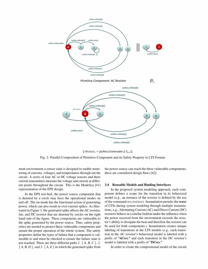
through a modeling tool such as the Labelled TransitionSystem Analyzer (LTSA) [37] to provide compilation ofFSPs into a Labelled Transition System (LTS) [37, 38].The LTS model is expressed graphically by its alphabet,transition relation, and states including single initial state(Figure 2). The LTS of the system is constructed fromthe LTS of its subsystems, and is verified against safetyproperties of the design requirements. In this research, themodel checking algorithm is integrated as part of the LTSAtool which performs exhaustive execution of all system’sbehavior to determine if the safety property is violatedor not. The LTSA takes advantage of the method calledcompositional reachability analysis (CRA) and creates areachability graph for the system which contains informationabout the safety values of each state. A safety property thenis checked by analyzing the reachability graph, searchingfor paths on which the safety property is violated. LabelledTransition Systems (LTS) T is defined as:
A set S of statesA set L of actionsA set→ of transitions from one state to another.An initial state s0 ∈ ST = (S,L,→,s0).
3.2 Parallel Composition of LTSsIn this section the parallel composition operator [39]
and the composition mechanism that assists with composi-tional modeling of the component models are explained. Theparallel composition operator enables both associative andcommutative composition; therefore the order of LTSs mod-els that are composed together is insignificant. The paral-lel composition operator, denoted by ”‖”, is a binary oper-ator that accepts two LTSs as an input argument. Based onthe definition of this operator, composed LTSs interact bysynchronizing on common actions (i.e., exchange of EMS)shared in their FSP models with interleaving of the remain-ing actions. Designing interacting components with LTSs istherefore sensitive to the selection of action names. In ad-dition, parallel composition is based on the model instantia-tion which is defined by constructing a copy of a LTS modelwhere each transition label is prefixed by the name of theinstance.
3.3 Electrical Power System DesignValidation of the proposed verification framework is
through application to an Electrical Power System (EPS)which is designed to provide power to selected loads. Inan aerospace vehicle these loads usually include subsys-tems such as the propulsion, avionics, and thermal man-agement systems. The basic functionality that EPS is re-quired to provide is common to many aerospace applicationssuch as power storage, power distribution, and operation ofloads [40]. Figure 3 displays the existing design of the EPS,containing a power source connected through a series of re-lays to an inverter and several loads consisting of a largefan, a Direct Current (DC) resistor and a Alternating Current(AC) resistor. In order to create an integrated health manage-
0-1
acRes.burn
Perr
0
acRes.inflow[2] acRes.burn
1 2
acRes.inflow[0..1]
3 4
acRes.inflow[1]
acRes.inflow[0]
acRes.inflow[1]
acRes.inflow[0]
acRes:Vulnerable
acRes.inflow[2]
||
0
acRes.inflow[2]
acRes.burn
1-1 3 4
acRes.inflow[1]
acRes.inflow[0]
acRes.inflow[1]
acRes.inflow[0]
|| = (acRes:(Vulnerable || )).
Fig. 2: Parallel Composition of Primitive Component and its Safety Property in LTS Format
ment environment a sensor suite is designed to enable moni-toring of currents, voltages, and temperatures through out thecircuit. A series of four AC or DC voltage sensors and threecurrent transmitters measure the voltage and current at differ-ent points throughout the circuit. This is the Modelica [41]representation of the EPS design.
In the EPS test-bed, the power source component thatis denoted by a circle may have the operational modes onand off. The on-mode has the functional action of generatingpower, which can also result in over-current spikes. As illus-trated in Figure 3, the generated spike affects the AC resistor,fan, and DC resistor that are denoted by circles on the righthand side of the figure. These components are vulnerable tothe spike generated by the power source. Thus, safety prop-erties are needed to protect these vulnerable components andensure the proper operation of the whole system. The safetyproperties define the types of failure that a component is vul-nerable to and must be checked to ensure the failure state isnot reached. There are three different paths 1. { A, B, C }, 2.{ A, B, D }, and 3. { A, E } in which the generated spike from
the power source can reach the three vulnerable components;these are considered design flaws [42].
3.4 Reusable Models and Binding InterfacesIn the proposed system modeling approach, each com-
ponent defines a scope for the transition in its behavioralmodel (e.g., an instance of the resistor is defined by the useof the command res:resistor). Instantiation permits the reuseof LTSs during system modeling through multiple instantia-tions, e.g., Alternating Current (AC) and Direct Current (DC)resistors behave in a similar fashion under the influence whenthe power received from the environment exceeds the resis-tor’s ability to dissipate the heat and therefore the resistor canbe used for both components.) Instantiation creates uniquelabeling of transitions in the LTS models (e.g., each transi-tion in the AC resistor’s behavioral model is labeled with aprefix of ”ACres.” and each transition in the DC resistor’smodel is labeled with a prefix of ”DCres.”
In order to create the compositional model of the circuit

Fig. 3: Structural Model of the EPSbreaker and AC resistor, an instance of the circuit breaker isdefined by the use of the command cb:CircuitBreaker that iscomposed with the previously defined instance ACres. How-ever, the two LTSs do not have any alphabet in common sono synchronization is possible. For this reason, the bindingbetween the two models is created by the use of the com-mand ACres.inflow/cb.outflow. The binding leads to a modelwhere the circuit breaker’s output current is recognized asthe AC resistor’s input current. As a result, the new labelACres.inflow, is substituted with the old label, cb.outflow.With the binding command in place, the synchronizationtakes place and the LTSs components have a common actionto communicate.
In our context, properties are modeled as safety LTSs.A safety LTS is a LTS that contains no failure states. Whenchecking a property P, an error LTS denoted Perr is created,which identifies possible violations with the failure state.
3.5 Verification ProcessThe contribution of this paper is developing an auto-
mated design verification framework to prove the correctnessof the complex engineered system design with regards to itsfunctional and safety properties. The proposed frameworkprovides information on the property violation of the com-posed components during conceptual design, while identify-ing the failure propagation behavior. The automatic genera-tion of failure propagation paths enables the system design-ers to better address the safety issues in the design. Figure 4depicts the relationship between system models and the ver-ification framework that either provides the proof of correct-ness or failure propagation information.The main steps to apply the assume-guarantee reasoning(AGR) framework are summarized as follows:
1. A functional model is generated as a representation ofall the necessary functions that the system must containin order to meet the design requirements is used to createthe structural model of the system.
System ModelFunctional Model
Structural Model(Chosen Design)
LTSA Verification Tool
FSP
LTS
Automated Model Checking(Assume-Guarantee Reasoning)
Database of Failure Modes
Component Behavioral Model
Does Design Meet Its
Requirements?
1. Generate Assume-guarantee Pair2. Generate Failure Propagation Paths
1. Generate Assume-guarantee Pair
YesNo
Fig. 4: An Overview of the Proposed Verification Process.
2. The structural model is used as a resource to gather in-formation about the different system components andthe Energy, Material, and Signal (EMS) flow relation-ship between them to create a database of their failurestates and safety properties and the behavioral models.
3. Once the behavioral models of the component are de-veloped, they are incorporated into the Finite State Pro-cesses (FSP) by mapping the behavior models with theirrespective FSPs’ transitions.
4. The Labeled Transition System (LTS) of the system isautomatically constructed from the FSP models that aredeveloped by design engineers.
5. The LTSs are incrementally analyzed and abstracted

through the use of a reachability graph to determinewhether the safety property is violated.
6. If the failure state of the component is reached, then thefailure propagation path is provided.
The AGR paradigm requires exact identification of the com-ponent properties, which in this case are defined based onthe failed states, of the components and (sub)systems. In or-der to identify the failed states the effects of incoming EMSflows on the operation of the components is analyzed and twogeneric states of nominal and failed are defined. The com-ponent’s state is recognized as nominal when a componentis operating with the performance and functionality intendedby the system designer. On the other hand, failure state isdefined as a component functioning in a way that was notintended by the designer.
3.6 Automated Model Checker Based On Assume-Guarantee Reasoning
In the assume-guarantee paradigm, the formula is atriplet 〈A〉M 〈P〉, where M is a component, P is a property,and A is an assumption about M’s environment. The formulais true if whenever M is part of a system satisfying A, thenthe system must also guarantee P.
Let M be a finite-state component (Table 1) with Σ beingthe set of its interaction points with the environment, and letP be a safety property. Then there is a natural notion of theweakest assumption Aw, such that 〈Aw〉M 〈P〉 holds, whereAw = Σ. Aw characterizes all possible environments E underwhich the property holds.
It has been shown that, for any finite-state componentM, the weakest assumption Aw exists and can be constructedalgorithmically [5]. An ideal Aw should precisely representthe component in all its intended usages. It should be safe,meaning that it should exclude all problematic interactions,and permissive, in that it should include all the good interac-tions.
A weakest assumption is generated so that it is both safeand permissive. Safety in this context means to restrict thebehaviors of the component to those that satisfy P. Permis-siveness, on the other hand is concerned with restricting be-haviors only if necessary. Permissiveness is desirable, be-cause Aw is then appropriate for deciding whether an envi-ronment E is suitable for M (if E does not satisfy Aw, thenE ‖ M does not satisfy P). The simplest assume guaranteerule for checking a safety property P on a system with twocomponents M1 and M2 is defined as
Rule ASYM:
1 : 〈A〉M1 〈P〉2 : 〈true〉M2 〈A〉〈true〉M1 ‖M2 〈P〉
In this rule, A denotes an assumption about the environmentof M1. Note that the rule is not symmetric in its use of thetwo components and does not support circularity. Despite itssimplicity, experience has shown it to be quite useful in thecontext of checking safety properties.
Model Checking
Learning Algorithm 1. AiM1 P
2. trueM2 Ai
Ai
True
False
Failure Propagation Path – Strengthen the Assumption
P is satisfied in ||
Failure?
False
True
P is violated in ||YesNo
Failure Propagation Path – Weaken the Assumption
Fig. 5: The Algorithm that Generates Assumptions.
The objective is to automatically generate the weakest as-sumptions for components and their compositions, so thatthe assume-guarantee rule is derived in an incremental man-ner. In this research, the algorithm in [43] is used to gen-erate approximate assumptions and guarantees at the com-ponent, subsystem, and system level. Figure 5 depicts thealgorithm which is based on model checking and machinelearning techniques to construct an initial assumption derivedfrom component’s behaviorial models. Model checking isused to make sure the generated assumption is safe and per-missive based on the assume-guarantee rule. The first step ofthe algorithm is to check for the first part of the Rule ASym:〈A〉M1 〈P〉. If it is violated, it means that the assumption istoo weak so it does not prevent M1 from reaching its failurestate. Based on the generated failure propagation path, thealgorithm creates a new assumption which is stronger thanthe previous one. The iteration continues until the first rule of〈A〉M1 〈P〉 is addressed. The next step is to check the secondrule 〈true〉M2 〈A〉. If the rule holds then it is concluded that〈true〉M1 ‖M2 〈P〉, otherwise the failure propagation pathis generated to provide the reason why component M2 is notable to guarantee A . Then the counterexample is analyzedto realize if component M1 reaches its failure state or not.If M1 does not reach its failure states then the assumption istoo strong and should be weakened and tested again. Oth-erwise, it is concluded that the composition of M1 ‖M2 vio-lates property P.
3.6.1 Soundness and Completeness
Soundness of an assume-guarantee rule means thatwhenever its premises hold, its conclusion holds as well.Without soundness, we cannot rely on the correctness of con-clusions reached by applications of the rule, which makes therule useless for verification. On the other hand, completenessstates that whenever the conclusion of the rule is correct, therule is applicable, i.e., there exist suitable assumptions suchthat the premises of the rule hold. While completeness is notneeded to ensure correctness of proofs obtained by the rule,it is important as a measure for the usability of the rule [5].

StoreElec. E
SupplyElec. E
SenseVoltage
SenseCurrent
ActuateElec. E
ActuateElec. E
SenseVoltage
ActuateElec. E
SenseVoltage
SenseCurrent
ConditionElec. E
ActuateElec. E
SenseVoltage
SenseCurrent
ActuateElec. E
ActuateElec. E
ActuateElec. E
ConvertElec. E
ConvertElec. E
ConvertElec. E
Fig. 6: Functional Model of the Electrical Power System.
3.7 The LTSA ToolThe Labeled Transition System Analyzer (LTSA) [37,
44] is an automated tool that supports Compositional Reach-ability Analysis (CRA) [28] of a software system based onits architecture. In general, the conceptual design of a com-plex engineered system has a hierarchical structure and ismodular [45]. CRA incrementally computes and abstractsthe behavior of composite components based on the behav-ior of their immediate children in the hierarchy. The inputlanguage ”FSP” of the tool is a process-algebra style nota-tion with Labeled Transition Systems (LTS) semantics.
A property is also expressed as an LTS, but with ex-tended semantics, and is treated as an ordinary componentduring composition. Properties are combined with the com-ponents to which they refer. They do not interfere with sys-tem behavior unless they are violated. In the presence of vio-lations, the properties introduced may reduce the state spaceof the (sub)systems analyzed. As in our approach, the LTSAframework treats components as open systems that may onlysatisfy some requirements in specific contexts. By compos-ing components with their properties it postpones analysisuntil the system is closed, meaning that all contextual behav-ior that is applicable has been provided.
4 Case StudyContinuing with the EPS design concept, the develop-
ment of LTSs implies direct mapping between the functionalmodel (Figure 6) and the structural architecture of the sys-tem, in which specific component or (sub)system is selectedto implement the functional requirements in the actual sys-tem design.
In order to construct the LTS model of the EPS design,all internal state transitions of the components are presentedin the Finite State Processes (FSP) language. The constantvariables(factors that do not change during the course of thisexperiment) and ranges are defined as follows:
const Low = 0const Medium = 1const Spike = 2const Open = 1const Close = 0range CUR = Low..Spike
The notations 0,1, and 2 are used to denote low, medium, andspike currents in the EPS components, respectively.
4.1 Primitive Components and PropertiesAs depicted in Table 1 all internal state transitions of
the primitive components are presented in the FSP language.
Each component’s nominal behavioral model is incorporatedinto the FSP code, therefore the resulting model contains nofailure state. For example, while the AC resistor is in the op-erational mode (Table 1), two transitions are possible, whichare specified using the ”OR” logical operator ”|” . These twotransitions are defined as: 1- the current input into the ACresistor which is in the range of low or medium and the re-sulting output current also in the low or medium range 2- thecurrent in-flow to the AC resistor is spiking which results inthe state of ”burn”. If the resistor is in the state of burn, nomatter what input current level to the AC resistor, there is nooutput current past the AC resistor.
Table 1: EPS Components and their FSP Models
EPS System
Component Mode FSP Model
Battery nominal (inflow[v:CUR]→ outflow[v]→ Battery)
Current Sensor nominal (inflow[v:CUR]→ outflow[v]→ Current Sensor)
Voltage Sensor nominal (inflow[v:CUR]→ outflow[v]→ Voltage Sensor)
Relay nominal (inflow[v:CUR]→ if (Open) then(outflow[v]→ Relayelse Relay))
Inverter nominal (inflow[v:CUR]→ outflow[v]→ Inverter)
AC Resistor nominalfailure
Operational =(inflow[v:CUR]→ outflow[v]→ Operational| inflow[Spike]→ burn→ BURNED),Burned = (inflow[CUR]→ Burned)
DC Resistor nominalfailure
same as AC Resistor
Fan nominalfailure
same as AC Resistor
The failure modes of components are represented by Perr.The error LTSs are constructed to represent all the faultytransitions that lead to failure states. In order to model thefailure mode of the three vulnerable components discussedin design architecture of Figure 3, a generic property namedPerr is defined for all three components as below:
property Perr = STOP + burn.The LTSA tool represents failure state by -1 as it is depictedin Figure 2 in the compositional model of the AC resistorwith its property that is reached by the illegal transition ofacres.burn.
4.2 Compositional ModelIn order to create the compositional model of the EPS
system, the order of compositions is decided based on thefunctional model of the design. Table 2 represents the com-positional model of the EPS system for two types of com-ponents. Those components that operate in nominal mode
inflow[0].2BATinflow[1].2BAT
inflow[2].2BAT
inflow[0].240CS
inflow[1].240CS
inflow[2].240CS
inflow[0].240VMinflow[1].240VM
inflow[2].240VM
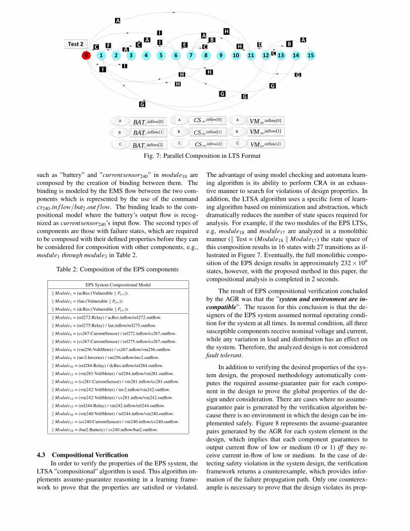
Fig. 7: Parallel Composition in LTS Format
such as ”battery” and ”currentsensor240” in module18 arecomposed by the creation of binding between them. Thebinding is modeled by the EMS flow between the two com-ponents which is represented by the use of the commandcs240.in f low/bat2.out f low. The binding leads to the com-positional model where the battery’s output flow is recog-nized as currentsensor240’s input flow. The second types ofcomponents are those with failure states, which are requiredto be composed with their defined properties before they canbe considered for composition with other components, e.g.,module1 through module3 in Table 2.
Table 2: Composition of the EPS components
EPS System Compositional Model
‖Module1 = (acRes:(Vulnerable ‖ Perr)).
‖Module2 = (fan:(Vulnerable ‖ Perr)).
‖Module3 = (dcRes:(Vulnerable ‖ Perr)).
‖Module4 = (rel272:Relay) / acRes.inflow/rel272.outflow.
‖Module5 = (rel275:Relay) / fan.inflow/rel275.outflow.
‖Module6 = (cs267:CurrentSensor) / rel272.inflow/cs267.outflow.
‖Module7 = (cs267:CurrentSensor) / rel275.inflow/cs267.outflow.
‖Module8 = (vm256:VoltMeter) / cs267.inflow/vm256.outflow.
‖Module9 = (inv2:Inverter) / vm256.inflow/inv2.outflow.
‖Module10 = (rel284:Relay) / dcRes.inflow/rel284.outflow.
‖Module11 = (vm281:VoltMeter) / rel284.inflow/vm281.outflow.
‖Module12 = (cs281:CurrentSensor) / vm281.inflow/cs281.outflow.
‖Module13 = (vm242:VoltMeter) / inv2.inflow/vm242.outflow.
‖Module14 = (vm242:VoltMeter) / cs281.inflow/vm242.outflow.
‖Module15 = (rel244:Relay) / vm242.inflow/rel244.outflow.
‖Module16 = (vm240:VoltMeter) / rel244.inflow/vm240.outflow.
‖Module17 = (cs240:CurrentSensor) / vm240.inflow/cs240.outflow.
‖Module18 = (bat2:Battery) / cs240.inflow/bat2.outflow.
4.3 Compositional VerificationIn order to verify the properties of the EPS system, the
LTSA ”compositional” algorithm is used. This algorithm im-plements assume-guarantee reasoning in a learning frame-work to prove that the properties are satisfied or violated.
The advantage of using model checking and automata learn-ing algorithm is its ability to perform CRA in an exhaus-tive manner to search for violations of design properties. Inaddition, the LTSA algorithm uses a specific form of learn-ing algorithm based on minimization and abstraction, whichdramatically reduces the number of state spaces required foranalysis. For example, if the two modules of the EPS LTSs,e.g, module18 and module17 are analyzed in a monolithicmanner (‖ Test = (Module18 ‖Module17) the state space ofthis composition results in 16 states with 27 transitions as il-lustrated in Figure 7. Eventually, the full monolithic compo-sition of the EPS design results in approximately 232× 109
states, however, with the proposed method in this paper, thecompositional analysis is completed in 2 seconds.
The result of EPS compositional verification concludedby the AGR was that the ”system and environment are in-compatible”. The reason for this conclusion is that the de-signers of the EPS system assumed normal operating condi-tion for the system at all times. In normal condition, all threesusceptible components receive nominal voltage and current,while any variation in load and distribution has an effect onthe system. Therefore, the analyzed design is not consideredfault tolerant.
In addition to verifying the desired properties of the sys-tem design, the proposed methodology automatically com-putes the required assume-guarantee pair for each compo-nent in the design to prove the global properties of the de-sign under consideration. There are cases where no assume-guarantee pair is generated by the verification algorithm be-cause there is no environment in which the design can be im-plemented safely. Figure 8 represents the assume-guaranteepairs generated by the AGR for each system element in thedesign, which implies that each component guarantees tooutput current flow of low or medium (0 or 1) iff they re-ceive current in-flow of low or medium. In the case of de-tecting safety violation in the system design, the verificationframework returns a counterexample, which provides infor-mation of the failure propagation path. Only one counterex-ample is necessary to prove that the design violates its prop-

Fig. 8: Assume-Guarantee Pair for the EPS Design of Fig. 3.
erties. In the case of EPS design, the failure propagationpath starts from ”battery” propagating through different com-ponents such as CurrentSensor240, VoltMeter240, Relay244,VoltMeter242, Inverter2, VoltMeter256, CurrentSensor267,Relay272 and reaching the ”AC resistor” causing it to burn.The ”inflow.2” represents the existence of the spike in theincoming and outgoing current flow in each component.
4.4 Design Based On The Result Of VerificationIn order to correct the design flaws mentioned above, it
is required to add circuit breakers to the design as modeledin Figure 9 to prevent the spike reaching the three vulner-able components. The circles highlight the circuit breakersused to protect the AC resistor, fan, and DC resistor froman over-current spike. The operation of the circuit breaker issimilar to that of an electrical switch, which is designed toprotect an electrical circuit from damage caused by overloador short circuit (Table 3). Therefore, the integration of cir-cuit breakers in the design architecture prevents the resistorsand fan from burning. The following equation represents theassume-guarantee reasoning rule of triple type:
1. <{0..1}> ACResistor <No Burn>2. <true> CircuitBreaker <{0..1}>
<true> AC Resistor ‖ Circuit Breaker <No Burn>
(1) <{0..1}> AC resistor <No Burn> is proven cor-rect if circuit breaker satisfies the assumption that in-flowcurrent to the AC resistor is always {0..1}, resulting inguaranteeing property No Burn.
The compositional model of the modified design isTable 3: FSP Code for Circuit Breaker
Circuit Breaker
Component Mode LTS Model
Circuit Breaker nominal (inflow[v:CUR]→ if ( v < Spike) then(outflow[v]→ CircuitBreaker)else CircuitBreaker) + {outflow[Spike]}
Table 4: Composition of the EPS components
EPS System Compositional Model
‖Module1 = (acRes:(Vulnerable ‖ Perr)).
‖Module2 = (fan:(Vulnerable ‖ Perr)).
‖Module3 = (dcRes:(Vulnerable ‖ Perr)).
‖Module4 = (rel272:Relay) / acRes.inflow/rel272.outflow.
‖Module5 = (rel275:Relay) / fan.inflow/rel275.outflow.
‖Module6 = (cs267:CurrentSensor) / rel272.inflow/cs267.outflow.
‖Module7 = (cs267:CurrentSensor) / rel275.inflow/cs267.outflow.
‖Module8 = (cb266:CircuitBreaker) / cs267.inflow/cb266.outflow.
‖Module9 = (vm256:VoltMeter) / cb266.inflow/vm256.outflow.
‖Module10 = (inv2:Inverter) / vm256.inflow/inv2.outflow.
‖Module11 = (cb262:CircuitBreaker) / inv2.inflow/cb262.outflow.
‖Module12 = (rel284:Relay) / dcRes.inflow/rel284.outflow.
‖Module13 = (vm281:VoltMeter) / rel284.inflow/vm281.outflow.
‖Module14 = (cs281:CurrentSensor) / vm281.inflow/cs281.outflow.
‖Module15 = (cb280:CircuitBreaker) / cs281.inflow/cb280.outflow.
‖Module16 = (vm242:VoltMeter) / cb262.inflow/vm242.outflow.
‖Module17 = (vm242:VoltMeter) / cb280.inflow/vm242.outflow.
‖Module18 = (rel244:Relay) / vm242.inflow/rel244.outflow.
‖Module19 = (vm240:VoltMeter) / rel244.inflow/vm240.outflow.
‖Module20 = (cs240:CurrentSensor) / vm240.inflow/cs240.outflow.
‖Module21 = (cb236:CircuitBreaker) / cs240.inflow/cb236.outflow.
‖Module22 = (bat2:Battery) / cb236.inflow/bat2.outflow.
represented in Table 4. The full monolithic compositionof the modified EPS design results in 19 × 1012 states,however, with the proposed method in this paper, thecompositional analysis is completed in 2.5 seconds. Theresult of verification is successful, implying that the ”systemand environment are compatible” and all the design safetyrequirements are met.
It is important to note that the generated assume-guarantee pairs, as depicted in Table 5, restrict the current-inflow of low and medium, [0,1], for a smaller number ofcomponents, compared to the EPS design without the circuitbreakers. The reason for this is that the circuitbreaker266 de-tects a fault condition and interrupt current flow from reach-ing the two vulnerable components (AC resistor and fan)in the top branch, while the circuitebreaker280 protects thelower branch. Therefore, any components before thesetwo circuit breakers can accept the in-flow current of low,medium, and spike. This is a good indication of the weakestassumptions generated by the proposed framework, guidingthe designers in their understanding of the design require-ments. Based on the generated assumptions the two circuitbreakers (236 and 262) are not required and therefore can beeliminated from the design.
The second alternative design architecture of the EPSsystem with removed circuit breakers has been verified as asafe design. Tables 6 illustrates the assume-guarantee pairgenerated for each design component.
As illustrated, the generated assume-guarantee pair iscritical in choosing alternative design solutions and migrat-ing between different design architectures with relativelysmall effort. In addition, the generated assume-guaranteepair enables the system designers to trace the requirements

Fig. 9: Model of the EPS with Circuit Breaker.
Table 5: Generated Assume-Guarantee Pair of Fig. 9
For EPS Design of Fig. 9
Component Assumption Guarantee
Battery [0,1,2] [0,1,2]
Circuit Breaker236 [0,1,2] [0,1]
Volt Meter240 [0,1,2] [0,1,2]
Current Sensor240 [0,1,2] [0,1,2]
Relay244 [0,1,2] [0,1,2]
Volt Meter242 [0,1,2] [0,1,2]
Circuit Breaker262 [0,1,2] [0,1]
Invertor2 [0,1,2] [0,1,2]
Circuit Breaker266 [0,1,2] [0,1]
Volt Meter265 [0,1] [0,1]
Current Sensor267 [0,1] [0,1]
Relay272 [0,1] [0,1]
Relay275 [0,1] [0,1]
ACResistor [0,1] [0,1]
Fan [0,1] [0,1]
Circuit Breaker280 [0,1,2] [0,1]
Current Sensor281 [0,1] [0,1]
Relay284 [0,1] [0,1]
Volt Meter281 [0,1] [0,1]
DCResistor [0,1] [0,1]
throughout the design architecture. The behavior of the sys-tem design is described in an assume-guarantee style spec-ification: a component guarantees certain set of behaviors,given that its environment follows certain assumptions.
In addition, a performance case study is conducted bycomparing the performance results of the proposed verifi-cation approach with a monolithical approach (Figure 10)which represents linear growth for the proposed verificationprocess, while an exponential growth is predicted for themonolithical verification process.
Table 6: Generated Assume-Guarantee Pair (Remove Un-necessary Circuit Breakers)
Improved EPS Design
Component Assumption Guarantee
Battery [0,1,2] [0,1,2]
ACResistor [0,1] [0,1]
Volt Meter240 [0,1,2] [0,1,2]
Current Sensor240 [0,1,2] [0,1,2]
Relay244 [0,1,2] [0,1,2]
Volt Meter242 [0,1,2] [0,1,2]
Invertor2 [0,1,2] [0,1,2]
Circuit Breaker266 [0,1,2] [0,1]
Volt Meter265 [0,1,2] [0,1,2]
Relay272 [0,1] [0,1]
Current Sensor267 [0,1] [0,1]
Relay275 [0,1] [0,1]
Fan [0,1] [0,1]
Circuit Breaker280 [0,1,2] [0,1]
Current Sensor281 [0,1] [0,1]
Relay284 [0,1] [0,1]
Volt Meter281 [0,1] [0,1]
DCResistor [0,1] [0,1]
5 Conclusion and Future WorkThis work provides a framework for the effective use
of formal methods in the early verification of safety require-ments in safety critical systems. This is especially impor-tant in proving the correctness of the system design, whereit is critical to guarantee that the known interactions be-tween system components do not violate any safety prop-erties. With regard to the design of complex systems, highlevel system requirements are decomposed into componentand (sub)system requirements which logically map to the ar-chitectural decomposition of the system. Therefore, proof of

Fig. 10: Verification Time of Monolithic Composition Vs.AGR Approach.
correctness through pre-verification of system componentsand compositional reasoning is made possible. The aim ofcompositional reasoning is to improve scalability of the de-sign verification problem by decomposing the original verifi-cation task into sub-problems. The simplification is based onthe assume-guarantee reasoning that results in approximatingthe requirements which a component and (sub)system placeson its operational environment to satisfy safety properties.The case study of the EPS design demonstrated the capabil-ity of the proposed verification methodology to perform vir-tual integration of system elements and proving system-levelrequirements from the constraints allocated on the compo-nents. As a result, a class of design flaws has been uncov-ered because of an integration failure that occurs when sys-tem components satisfy their requirements in isolation butnot at the system-level.
The proposed approach models the behavior of com-posite components using LTS models of the primitive com-ponents and their safety properties, which are based on thestructural model provided by the Modelica model of the sys-tem design. In addition, a fully automated compositionalverification technique is used to determine the correctnessof the design with regards to its requirement and generatepairs of assume-guarantee using a learning algorithm. Ex-perimental results showed the effectiveness of the composi-tional reasoning approach in reducing the complexity of theverification process by using modularity and abstraction. Inaddition, we showed how a deductive verification tool suchas LTSA combined with LTS models can be used for verifi-cation of finite-state hardware system designs. The composi-tional verification helps in breaking a large complex systemdesign into smaller parts whose verification can be checkedin order to prove that the safety property of the componentsand the (sub)system holds. The assume-guarantee approachwhich is based on a learning algorithm [5], produces andrefines assumptions depending on failure propagation pathsand queries, the verification process is assured [5] to ter-minate. In addition, the algorithm returns counterexampleswhich include failure propagation information in the earlystages of conceptual design. Another advantage of the pro-posed approach for verification of engineered systems is itsindependence from human intervention and expert user indevising the appropriate assume-guarantee pair. The experi-
ment in this paper provided strong evidence in favor of thisline of research.
It must be noted that state explosion is an inherent lim-itation of model checking, therefore no single technique isexpected to be efficient for all kinds of systems. This is alsoreflected by the fact that most of the existing model-checkingtools support several approaches to model checking. The fu-ture work will concentrate to build experience in order todetermine what types of analyses are appropriate for whatkinds of systems. Specifically, we will focus on the designverification and analysis of complex engineered systems withsoftware controlling the hardware. The design of such sys-tems requires collaboration between experts from differentdesign domains to formally define their interacting behaviorand verify conflicting requirements or objectives.
In addition, future work expands the approach discussedin this paper to examine the learning algorithm and its gen-erated assumptions to determine the most reliable design ar-chitecture of the redundant systems. It is our goal to investi-gate different aspects of fault tolerant system design require-ments while taking into account automatic injection of mul-tiple failures and reasoning about different types of recoverystrategies. As a result, the existing verification technique isrequired to be modified to include systems that exhibit prob-abilistic behavior. The approach will be based on the multi-objective probabilistic model checking. Properties of thesemodels are formally defined as probabilistic safety proper-ties.
References[1] Saporito, B., 2013. How Safe is the Boeing 787? See
also URL http://business.time.com/2013/01/11/how-safe-is-the-boeing-787/, Jan.
[2] ElMaraghy, H. A., 2009. “Changing and evolving prod-ucts and systems–models and enablers”. In Changeableand reconfigurable manufacturing systems. Springer,pp. 25–45.
[3] Foster, H., 2013. Prologue: The 2012 Wilson ResearchGroup Functional Verification Study,. American Insti-tute of Aeronautics & Astronautics.
[4] Inc., C. I. R., 2002. 2002 IC/ASIC Functional Verifica-tion Study.
[5] Giannakopoulou, D., Pasareanu, C. S., and Barringer,H., 2002. “Assumption Generation for Software Com-ponent Verification”. In Automated Software Engineer-ing, 2002. Proceedings. ASE 2002. 17th IEEE Interna-tional Conference on, IEEE, pp. 3–12.
[6] Cobleigh, J., Giannakopoulou, D., and Pasareanu, C.,2003. “Learning Assumptions for Compositional Ver-ification”. Tools and Algorithms for the Constructionand Analysis of Systems, pp. 331–346.
[7] Chaki, S., Clarke, E., Sinha, N., and Thati, P., 2005.“Automated Assume-guarantee Reasoning for Simula-tion Conformance”. In Computer Aided Verification,Springer, pp. 241–246.
[8] Alur, R., Madhusudan, P., and Nam, W., 2005. “Sym-bolic Compositional Verification by Learning Assump-

tions”. In Computer Aided Verification, Springer,pp. 289–292.
[9] Kazhamiakin, R., Pistore, M., and Roveri, M., 2004. “Aframework for integrating business processes and busi-ness requirements”. In Enterprise Distributed ObjectComputing Conference, 2004. EDOC 2004. Proceed-ings. Eighth IEEE International, IEEE, pp. 9–20.
[10] Baresi, L., Bianculli, D., Ghezzi, C., Guinea, S., andSpoletini, P., 2007. “Validation of web service compo-sitions”. IET software, 1(6), pp. 219–232.
[11] Henzinger, T. A., Minea, M., and Prabhu, V., 2001.“Assume-guarantee reasoning for hierarchical hybridsystems”. In Hybrid Systems: Computation and Con-trol. Springer, pp. 275–290.
[12] Feiler, P. H., Gluch, D. P., and Hudak, J. J., 2006. Thearchitecture analysis & design language (aadl): An in-troduction. Tech. rep., DTIC Document.
[13] Fritzson, P., 2010. Principles of object-oriented mod-eling and simulation with Modelica 2.1. John Wiley &Sons.
[14] Buck, J. T., Ha, S., Lee, E. A., and Messerschmitt,D. G., 1994. “Ptolemy: A framework for simulatingand prototyping heterogeneous systems”.
[15] Simulink, M., and Natick, M., 1993. “The mathworks”.Inc., Natick, MA.
[16] Friedenthal, S., Moore, A., and Steiner, R., 2011. Apractical guide to SysML: the systems modeling lan-guage. Elsevier.
[17] Caldwell, S., English, D., Foote, A., Hodges, V.,Nguyen, Q., Pecora, P. J., Pien, D., Stallings, Z., Tong,C., Vendiola, D., et al., 1993. “Risk assessment ma-trix”. multi-cultural guidelines for assessing familystrengths and risk factors in child protective services,p. 71.
[18] Roland, H. E., and Moriarty, B., 2009. “Preliminaryhazard analysis”. System Safety Engineering and Man-agement, Second Edition, pp. 206–212.
[19] Do, D., 1980. “Procedure for performing a failuremode, effects and criticality analysis”.
[20] Tumer, I. Y., and Stone, R. B., 2001. “Analyticalmethod for mapping function to failure during high-risk component development”. In Proceedings of theDesign Engineering Technical Conferences.
[21] Dhillon, B., and Fashandi, A., 1997. “Safety and re-liability assessment techniques in robotics”. Robotica,15(06), pp. 701–708.
[22] Cepin, M., 2011. “Reliability block diagram”. InAssessment of Power System Reliability. Springer,pp. 119–123.
[23] Ericson, C. A., and Ll, C., 2000. “Fault tree analysis”.Hazard analysis techniques for system safety, pp. 183–221.
[24] Clarke, E. M., Grumberg, O., and Peled, D., 1999.Model checking. MIT press.
[25] Baier, C., Katoen, J.-P., et al., 2008. Principles of modelchecking, Vol. 26202649. MIT press Cambridge.
[26] Henzinger, T., and Sifakis, J., 2006. “The EmbeddedSystems Design Challenge”. pp. 1–15.
[27] Pnueli, A., 1977. “The Temporal Logic of Programs”.In Foundations of Computer Science, 1977., 18th An-nual Symposium on, IEEE, pp. 46–57.
[28] Cheung, S. C., and Kramer, J., 1999. “Checking SafetyProperties Using Compositional Reachability Analy-sis”. ACM Transactions on Software Engineering andMethodology (TOSEM), 8(1), pp. 49–78.
[29] Kurtoglu, T., Campbell, M., Bryant, C., Stone, R., andMcAdams, D., 2005. “Deriving a component basisfor computational functional synthesis”. In Interna-tional conference on engineering design, ICED, Vol. 5,pp. 15–18.
[30] Kurtoglu, T., and Tumer, I. Y., 2007. “Ffip: A frame-work for early assessment of functional failures in com-plex systems”. In International Conference on Engi-neering Design.
[31] Wang, E. Y., and Cheng, B. H., 2000. “Formalizing thefunctional model within object-oriented design”. Inter-national Journal of Software Engineering and Knowl-edge Engineering, 10(01), pp. 5–30.
[32] Hirtz, J., Stone, R. B., McAdams, D. A., Szykman, S.,and Wood, K. L., 2002. “A functional basis for engi-neering design: reconciling and evolving previous ef-forts”. Research in engineering Design, 13(2), pp. 65–82.
[33] Stone, R. B., and Wood, K. L., 2000. “Development ofa functional basis for design”. Journal of MechanicalDesign, 122, p. 359.
[34] Kurtoglu, T., Tumer, I. Y., and Jensen, D. C., 2010.“A functional failure reasoning methodology for evalu-ation of conceptual system architectures”. Research inEngineering Design, 21(4), pp. 209–234.
[35] Otto, K., and Wood, K. Product design: Techniques inreverse engineering, systematic design, and new prod-uct development. 2001.
[36] Rodrigues, R. W., 2000. “Formalising UML ActivityDiagrams Using Finite State Processes”. In Proc. ofthe 3rd Intl. Conf. on the Unified Modeling Language,York, UK, Citeseer.
[37] Magree, J., 1999. “Behavioral analysis of software ar-chitectures using ltsa”. In Software Engineering, 1999.Proceedings of the 1999 International Conference on,IEEE, pp. 634–637.
[38] Gilreath, W. F., 2001. “Concurrency state models andjava programs”. Scalable Computing: Practice and Ex-perience, 3(4).
[39] Garavel, H., Sighireanu, M., et al., 1999. “A Graph-ical Parallel Composition Operator for Process Alge-bras”. In International Conference on Formal Descrip-tion Techniques for Distributed Systems and Commu-nication Protocols, and Protocol Specification, Test-ing, and Verification FORTE/PSTV, Vol. 99, Citeseer,pp. 185–202.
[40] Poll, S., Patterson-Hine, A., Camisa, J., Garcia, D.,Hall, D., Lee, C., Mengshoel, O. J., Neukom, C.,Nishikawa, D., Ossenfort, J., et al., 2007. “Advanceddiagnostics and prognostics testbed”. In Proceedings ofthe 18th International Workshop on Principles of Diag-

nosis (DX-07), pp. 178–185.[41] Tiller, M., 2001. Introduction to physical modeling with
Modelica, Vol. 615. Kluwer Academic Pub.[42] Mehrpouyan, H., Jensen, D. C., Hoyle, C., Tumer,
I. Y., and Kurtgolu, T., 2012. “A Model-based FailureIdentification and Propagation Framework for Concep-tual Design of Complex Systems”. Proceedings of theASME 2012 International Design Engineering Techni-cal Conferences and Computers and Information in En-gineering Conference.
[43] Giannakopoulou, D., Pasareanu, C. S., and Cobleigh,J. M., 2004. “Assume-guarantee verification of sourcecode with design-level assumptions”. In Proceedingsof the 26th International Conference on Software Engi-neering, IEEE Computer Society, pp. 211–220.
[44] Magee, J., Kramer, J., and Giannakopoulou, D., 1999.“Behaviour analysis of software architectures”. Soft-ware Architecture, 12, p. 35.
[45] Woodard, C. J., 2006. “Architectural strategy and de-sign evolution in complex engineered systems”. PhDthesis, Citeseer.