compliance with the following codes: • 2006 · pdf filecompliance with the following...
TRANSCRIPT
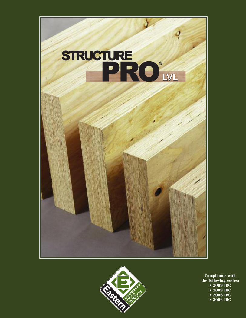
Compliance with the following codes:
• 2009 IBC• 2009 IRC• 2006 IBC• 2006 IRC
2 StructurePRO LVL Design Manual 1-800-700-4788
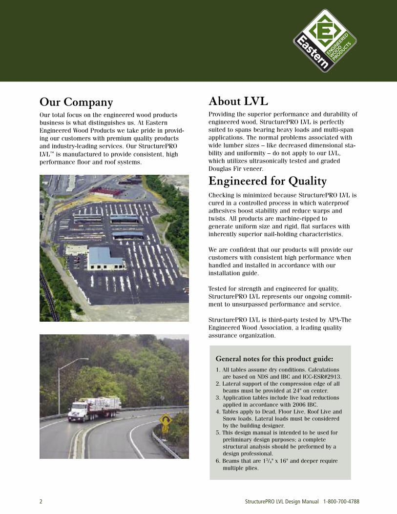
Our CompanyOur total focus on the engineered wood productsbusiness is what distinguishes us. At EasternEngineered Wood Products we take pride in provid-ing our customers with premium quality productsand industry-leading services. Our StructurePROLVL™ is manufactured to provide consistent, high performance floor and roof systems.
About LVL Providing the superior performance and durability ofengineered wood, StructurePRO LVL is perfectlysuited to spans bearing heavy loads and multi-spanapplications. The normal problems associated withwide lumber sizes – like decreased dimensional sta-bility and uniformity – do not apply to our LVL,which utilizes ultrasonically tested and gradedDouglas Fir veneer.
Engineered for QualityChecking is minimized because StructurePRO LVL iscured in a controlled process in which waterproofadhesives boost stability and reduce warps andtwists. All products are machine-ripped to generate uniform size and rigid, flat surfaces withinherently superior nail-holding characteristics.
We are confident that our products will provide ourcustomers with consistent high performance whenhandled and installed in accordance with our installation guide.
Tested for strength and engineered for quality,StructurePRO LVL represents our ongoing commit-ment to unsurpassed performance and service.
StructurePRO LVL is third-party tested by APA-TheEngineered Wood Association, a leading qualityassurance organization.
General notes for this product guide:1. All tables assume dry conditions. Calculations
are based on NDS and IBC and ICC-ESR#2913.2. Lateral support of the compression edge of all
beams must be provided at 24" on center.3. Application tables include live load reductions
applied in accordance with 2006 IBC.4. Tables apply to Dead, Floor Live, Roof Live and
Snow loads. Lateral loads must be considered by the building designer.
5. This design manual is intended to be used for preliminary design purposes; a complete structural analysis should be preformed by a design professional.
6. Beams that are 13/4" x 16" and deeper require multiple plies.
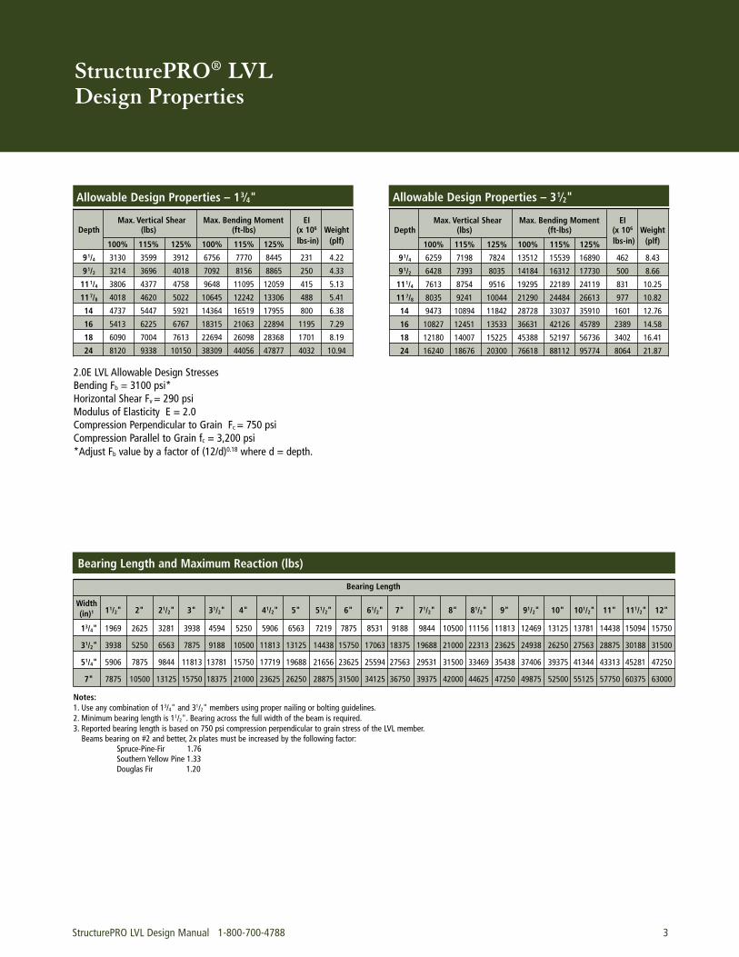
StructurePRO® LVL Design Properties
StructurePRO LVL Design Manual 1-800-700-4788 3
Allowable Design Properties – 31⁄2"Allowable Design Properties – 13⁄4"
2.0E LVL Allowable Design StressesBending Fb = 3100 psi*Horizontal Shear Fv = 290 psiModulus of Elasticity E = 2.0Compression Perpendicular to Grain Fc = 750 psiCompression Parallel to Grain fc = 3,200 psi*Adjust Fb value by a factor of (12/d)0.18 where d = depth.
Max. Vertical Shear Max. Bending Moment EIDepth (lbs) (ft-lbs) (x 106 Weight
100% 115% 125% 100% 115% 125% lbs-in) (plf)
91/4 3130 3599 3912 6756 7770 8445 231 4.22
91/2 3214 3696 4018 7092 8156 8865 250 4.33
111/4 3806 4377 4758 9648 11095 12059 415 5.13
117/8 4018 4620 5022 10645 12242 13306 488 5.41
14 4737 5447 5921 14364 16519 17955 800 6.38
16 5413 6225 6767 18315 21063 22894 1195 7.29
18 6090 7004 7613 22694 26098 28368 1701 8.19
24 8120 9338 10150 38309 44056 47877 4032 10.94
Max. Vertical Shear Max. Bending Moment EIDepth (lbs) (ft-lbs) (x 106 Weight
100% 115% 125% 100% 115% 125% lbs-in) (plf)
91/4 6259 7198 7824 13512 15539 16890 462 8.43
91/2 6428 7393 8035 14184 16312 17730 500 8.66
111/4 7613 8754 9516 19295 22189 24119 831 10.25
117/8 8035 9241 10044 21290 24484 26613 977 10.82
14 9473 10894 11842 28728 33037 35910 1601 12.76
16 10827 12451 13533 36631 42126 45789 2389 14.58
18 12180 14007 15225 45388 52197 56736 3402 16.41
24 16240 18676 20300 76618 88112 95774 8064 21.87
Width(in)1
Bearing Length and Maximum Reaction (lbs)
Bearing Length
Notes:1. Use any combination of 13/4" and 31/2" members using proper nailing or bolting guidelines.2. Minimum bearing length is 11/2". Bearing across the full width of the beam is required.3. Reported bearing length is based on 750 psi compression perpendicular to grain stress of the LVL member.Beams bearing on #2 and better, 2x plates must be increased by the following factor:
Spruce-Pine-Fir 1.76Southern Yellow Pine 1.33Douglas Fir 1.20
11/2" 2" 21/2" 3" 31/2" 4" 41/2" 5" 51/2" 6" 61/2" 7" 71/2" 8" 81/2" 9" 91/2" 10" 101/2" 11" 111/2" 12"
13/4" 1969 2625 3281 3938 4594 5250 5906 6563 7219 7875 8531 9188 9844 10500 11156 11813 12469 13125 13781 14438 15094 15750
31/2" 3938 5250 6563 7875 9188 10500 11813 13125 14438 15750 17063 18375 19688 21000 22313 23625 24938 26250 27563 28875 30188 31500
51/4" 5906 7875 9844 11813 13781 15750 17719 19688 21656 23625 25594 27563 29531 31500 33469 35438 37406 39375 41344 43313 45281 47250
7" 7875 10500 13125 15750 18375 21000 23625 26250 28875 31500 34125 36750 39375 42000 44625 47250 49875 52500 55125 57750 60375 63000
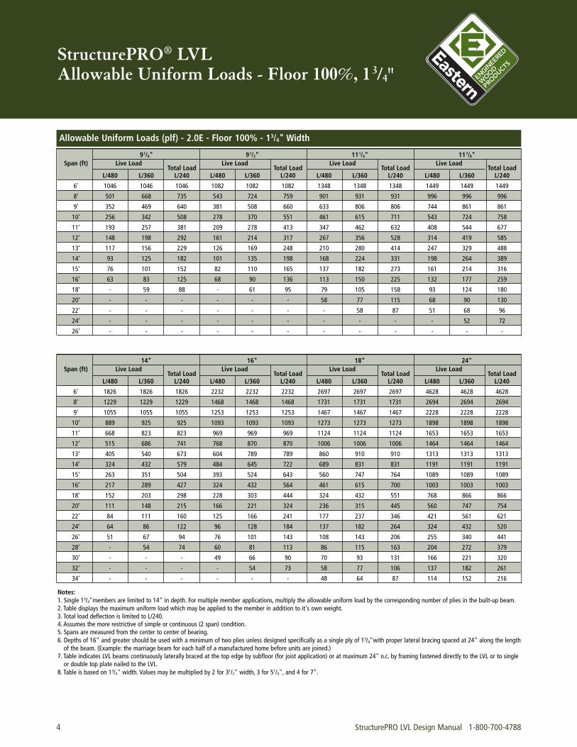
StructurePRO® LVL Allowable Uniform Loads - Floor 100%, 13/4"
4 StructurePRO LVL Design Manual 1-800-700-4788
14" 16" 18" 24"Span (ft) Live Load
Total LoadLive Load
Total LoadLive Load
Total LoadLive Load
Total LoadL/480 L/360 L/240 L/480 L/360 L/240 L/480 L/360 L/240 L/480 L/360 L/240
6’ 1826 1826 1826 2232 2232 2232 2697 2697 2697 4628 4628 4628
8’ 1229 1229 1229 1468 1468 1468 1731 1731 1731 2694 2694 2694
9’ 1055 1055 1055 1253 1253 1253 1467 1467 1467 2228 2228 2228
10’ 889 925 925 1093 1093 1093 1273 1273 1273 1898 1898 1898
11’ 668 823 823 969 969 969 1124 1124 1124 1653 1653 1653
12’ 515 686 741 768 870 870 1006 1006 1006 1464 1464 1464
13’ 405 540 673 604 789 789 860 910 910 1313 1313 1313
14’ 324 432 579 484 645 722 689 831 831 1191 1191 1191
15’ 263 351 504 393 524 643 560 747 764 1089 1089 1089
16’ 217 289 427 324 432 564 461 615 700 1003 1003 1003
18’ 152 203 298 228 303 444 324 432 551 768 866 866
20’ 111 148 215 166 221 324 236 315 445 560 747 754
22’ 84 111 160 125 166 241 177 237 346 421 561 621
24’ 64 86 122 96 128 184 137 182 264 324 432 520
26’ 51 67 94 76 101 143 108 143 206 255 340 441
28’ - 54 74 60 81 113 86 115 163 204 272 379
30’ - - - 49 66 90 70 93 131 166 221 320
32’ - - - - 54 73 58 77 106 137 182 261
34’ - - - - - - 48 64 87 114 152 216
91/4" 91/2" 111/4" 117/8"Span (ft) Live Load
Total LoadLive Load
Total LoadLive Load
Total LoadLive Load
Total LoadL/480 L/360 L/240 L/480 L/360 L/240 L/480 L/360 L/240 L/480 L/360 L/240
6’ 1046 1046 1046 1082 1082 1082 1348 1348 1348 1449 1449 1449
8’ 501 668 735 543 724 759 901 931 931 996 996 996
9’ 352 469 640 381 508 660 633 806 806 744 861 861
10’ 256 342 508 278 370 551 461 615 711 543 724 758
11’ 193 257 381 209 278 413 347 462 632 408 544 677
12’ 148 198 292 161 214 317 267 356 528 314 419 585
13’ 117 156 229 126 169 248 210 280 414 247 329 488
14’ 93 125 182 101 135 198 168 224 331 198 264 389
15’ 76 101 152 82 110 165 137 182 273 161 214 316
16’ 63 83 125 68 90 136 113 150 225 132 177 259
18’ - 59 88 - 61 95 79 105 158 93 124 180
20’ - - - - - - 58 77 115 68 90 130
22’ - - - - - - - 58 87 51 68 96
24’ - - - - - - - - - - 52 72
26’ - - - - - - - - - - - -
Allowable Uniform Loads (plf) - 2.0E - Floor 100% - 13/4" Width
Notes:1. Single 13/4"members are limited to 14" in depth. For multiple member applications, multiply the allowable uniform load by the corresponding number of plies in the built-up beam.2. Table displays the maximum uniform load which may be applied to the member in addition to it's own weight.3. Total load deflection is limited to L/240.4. Assumes the more restrictive of simple or continuous (2 span) condition.5. Spans are measured from the center to center of bearing.6. Depths of 16" and greater should be used with a minimum of two plies unless designed specifically as a single ply of 13/4"with proper lateral bracing spaced at 24" along the length of the beam. (Example: the marriage beam for each half of a manufactured home before units are joined.)
7. Table indicates LVL beams continuously laterally braced at the top edge by subfloor (for joist application) or at maximum 24" o.c. by framing fastened directly to the LVL or to single or double top plate nailed to the LVL.
8. Table is based on 13/4" width. Values may be multiplied by 2 for 31/2" width, 3 for 51/4", and 4 for 7".
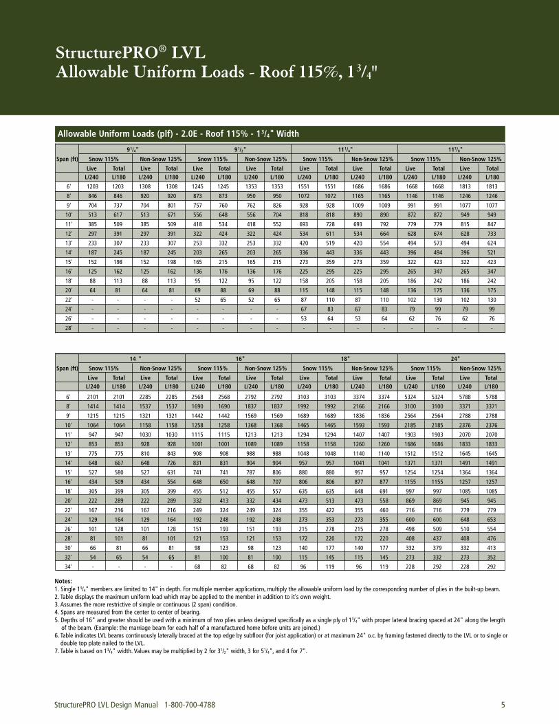
StructurePRO® LVL Allowable Uniform Loads - Roof 115%, 13/4"
StructurePRO LVL Design Manual 1-800-700-4788 5
Notes:1. Single 13/4" members are limited to 14" in depth. For multiple member applications, multiply the allowable uniform load by the corresponding number of plies in the built-up beam.2. Table displays the maximum uniform load which may be applied to the member in addition to it's own weight.3. Assumes the more restrictive of simple or continuous (2 span) condition.4. Spans are measured from the center to center of bearing.5. Depths of 16" and greater should be used with a minimum of two plies unless designed specifically as a single ply of 13/4" with proper lateral bracing spaced at 24" along the length of the beam. (Example: the marriage beam for each half of a manufactured home before units are joined.)
6. Table indicates LVL beams continuously laterally braced at the top edge by subfloor (for joist application) or at maximum 24" o.c. by framing fastened directly to the LVL or to single or double top plate nailed to the LVL.
7. Table is based on 13/4" width. Values may be multiplied by 2 for 31/2" width, 3 for 51/4", and 4 for 7".
91/4" 91/2" 111/4" 117/8"
Span (ft) Snow 115% Non-Snow 125% Snow 115% Non-Snow 125% Snow 115% Non-Snow 125% Snow 115% Non-Snow 125%
Allowable Uniform Loads (plf) - 2.0E - Roof 115% - 13/4" Width
Live Total Live Total Live Total Live Total Live Total Live Total Live Total Live TotalL/240 L/180 L/240 L/180 L/240 L/180 L/240 L/180 L/240 L/180 L/240 L/180 L/240 L/180 L/240 L/180
14 " 16" 18" 24"
Span (ft) Snow 115% Non-Snow 125% Snow 115% Non-Snow 125% Snow 115% Non-Snow 125% Snow 115% Non-Snow 125%
Live Total Live Total Live Total Live Total Live Total Live Total Live Total Live TotalL/240 L/180 L/240 L/180 L/240 L/180 L/240 L/180 L/240 L/180 L/240 L/180 L/240 L/180 L/240 L/180
6' 1203 1203 1308 1308 1245 1245 1353 1353 1551 1551 1686 1686 1668 1668 1813 1813
8' 846 846 920 920 873 873 950 950 1072 1072 1165 1165 1146 1146 1246 1246
9' 704 737 704 801 757 760 762 826 928 928 1009 1009 991 991 1077 1077
10' 513 617 513 671 556 648 556 704 818 818 890 890 872 872 949 949
11' 385 509 385 509 418 534 418 552 693 728 693 792 779 779 815 847
12' 297 391 297 391 322 424 322 424 534 611 534 664 628 674 628 733
13' 233 307 233 307 253 332 253 332 420 519 420 554 494 573 494 624
14' 187 245 187 245 203 265 203 265 336 443 336 443 396 494 396 521
15' 152 198 152 198 165 215 165 215 273 359 273 359 322 423 322 423
16' 125 162 125 162 136 176 136 176 225 295 225 295 265 347 265 347
18' 88 113 88 113 95 122 95 122 158 205 158 205 186 242 186 242
20' 64 81 64 81 69 88 69 88 115 148 115 148 136 175 136 175
22' - - - - 52 65 52 65 87 110 87 110 102 130 102 130
24' - - - - - - - - 67 83 67 83 79 99 79 99
26' - - - - - - - - 53 64 53 64 62 76 62 76
28' - - - - - - - - - - - - - - - -
6' 2101 2101 2285 2285 2568 2568 2792 2792 3103 3103 3374 3374 5324 5324 5788 5788
8' 1414 1414 1537 1537 1690 1690 1837 1837 1992 1992 2166 2166 3100 3100 3371 3371
9' 1215 1215 1321 1321 1442 1442 1569 1569 1689 1689 1836 1836 2564 2564 2788 2788
10' 1064 1064 1158 1158 1258 1258 1368 1368 1465 1465 1593 1593 2185 2185 2376 2376
11' 947 947 1030 1030 1115 1115 1213 1213 1294 1294 1407 1407 1903 1903 2070 2070
12' 853 853 928 928 1001 1001 1089 1089 1158 1158 1260 1260 1686 1686 1833 1833
13' 775 775 810 843 908 908 988 988 1048 1048 1140 1140 1512 1512 1645 1645
14' 648 667 648 726 831 831 904 904 957 957 1041 1041 1371 1371 1491 1491
15' 527 580 527 631 741 741 787 806 880 880 957 957 1254 1254 1364 1364
16' 434 509 434 554 648 650 648 707 806 806 877 877 1155 1155 1257 1257
18' 305 399 305 399 455 512 455 557 635 635 648 691 997 997 1085 1085
20' 222 289 222 289 332 413 332 434 473 513 473 558 869 869 945 945
22' 167 216 167 216 249 324 249 324 355 422 355 460 716 716 779 779
24' 129 164 129 164 192 248 192 248 273 353 273 355 600 600 648 653
26' 101 128 101 128 151 193 151 193 215 278 215 278 498 509 510 554
28' 81 101 81 101 121 153 121 153 172 220 172 220 408 437 408 476
30' 66 81 66 81 98 123 98 123 140 177 140 177 332 379 332 413
32' 54 65 54 65 81 100 81 100 115 145 115 145 273 332 273 352
34' - - - - 68 82 68 82 96 119 96 119 228 292 228 292
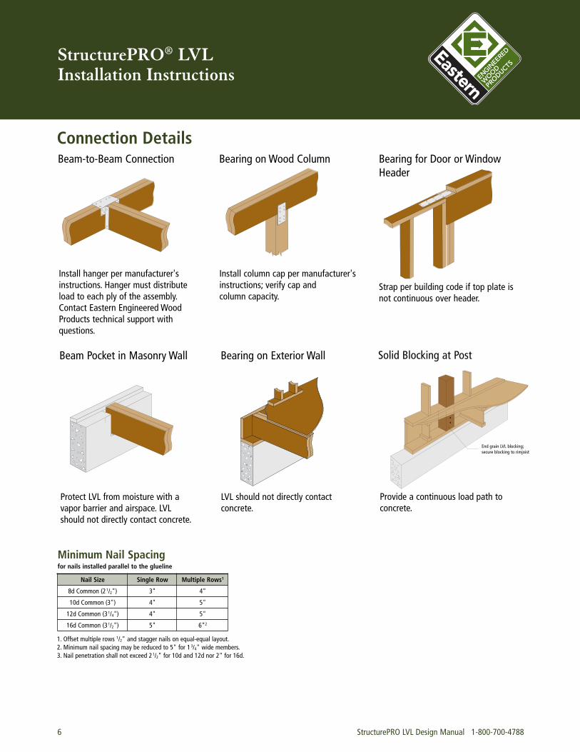
StructurePRO® LVLInstallation Instructions
6 StructurePRO LVL Design Manual 1-800-700-4788
Connection DetailsBeam-to-Beam Connection Bearing on Wood Column
Install hanger per manufacturer'sinstructions. Hanger must distributeload to each ply of the assembly.Contact Eastern Engineered WoodProducts technical support withquestions.
Install column cap per manufacturer'sinstructions; verify cap and column capacity.
Beam Pocket in Masonry Wall Bearing on Exterior Wall
Bearing for Door or Window Header
Protect LVL from moisture with avapor barrier and airspace. LVLshould not directly contact concrete.
LVL should not directly contact concrete.
Strap per building code if top plate isnot continuous over header.
Solid Blocking at Post
Provide a continuous load path toconcrete.
End grain LVL blocking;secure blocking to rimjoist
Nail Size Single Row Multiple Rows1
8d Common (21/2") 3" 4"
10d Common (3") 4" 5"
12d Common (31/4") 4" 5"
16d Common (31/2") 5" 6"2
Minimum Nail Spacingfor nails installed parallel to the glueline
1. Offset multiple rows 1/2" and stagger nails on equal-equal layout.2. Minimum nail spacing may be reduced to 5" for 13/4" wide members.3. Nail penetration shall not exceed 21/2" for 10d and 12d nor 2" for 16d.
StructurePRO LVL Design Manual 1-800-700-4788 7
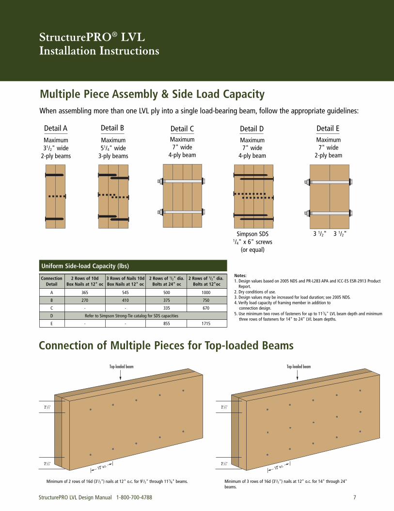
StructurePRO® LVLInstallation Instructions
Multiple Piece Assembly & Side Load CapacityWhen assembling more than one LVL ply into a single load-bearing beam, follow the appropriate guidelines:
Detail A Detail B Detail C Detail D
Notes:1. Design values based on 2005 NDS and PR-L283 APA and ICC-ES ESR-2913 Product Report.
2. Dry conditions of use.3. Design values may be increased for load duration; see 2005 NDS.4. Verify load capacity of framing member in addition to connection design.
5. Use minimum two rows of fasteners for up to 117/8" LVL beam depth and minimum three rows of fasteners for 14" to 24" LVL beam depths.
Maximum31/2" wide 2-ply beams
Maximum51/4" wide 3-ply beams
Maximum 7" wide
4-ply beam
Maximum 7" wide
4-ply beam
Simpson SDS1/4" x 6" screws
(or equal)
Uniform Side-load Capacity (lbs)
Detail EMaximum7" wide
2-ply beam
3 1/2" 3 1/2"
Connection 2 Rows of 10d 3 Rows of Nails 10d 2 Rows of 1/2" dia. 2 Rows of 1/2" dia. Detail Box Nails at 12" oc Box Nails at 12" oc Bolts at 24" oc Bolts at 12"oc
A 365 545 500 1000
B 270 410 375 750
C - - 335 670
D Refer to Simpson Strong-Tie catalog for SDS capacities
E - - 855 1715
Connection of Multiple Pieces for Top-loaded Beams
Top-loaded beam
21/2"
21/2"12" o.c.
Top-loaded beam
21/2"
21/2"12" o.c.
Minimum of 2 rows of 16d (31/2") nails at 12" o.c. for 91/2" through 117/8" beams. Minimum of 3 rows of 16d (31/2") nails at 12" o.c. for 14" through 24"beams.
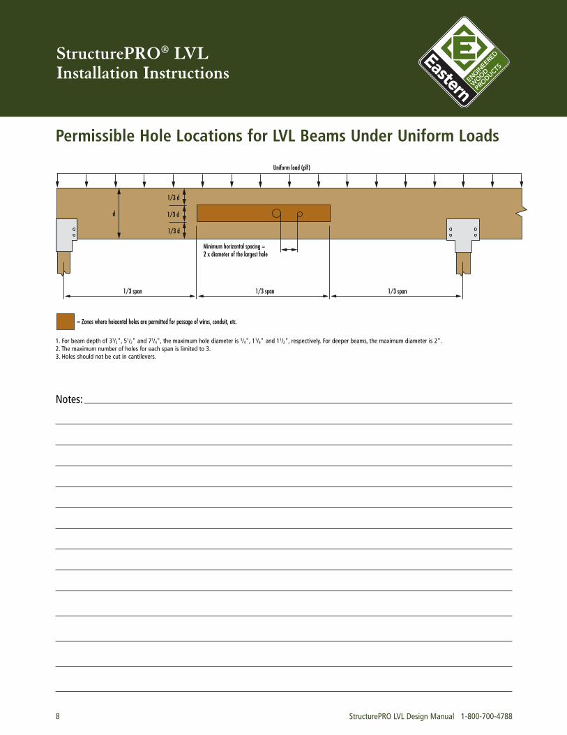
StructurePRO® LVLInstallation Instructions
1/3 d
1/3 d
1/3 d
d
1/3 span 1/3 span 1/3 span
Minimum horizontal spacing =2 x diameter of the largest hole
Uniform load (plf)
= Zones where hoiaontal holes are permitted for passage of wires, conduit, etc.
Permissible Hole Locations for LVL Beams Under Uniform Loads
1. For beam depth of 31/2", 51/2" and 71/4", the maximum hole diameter is 3/4", 11/8" and 11/2", respectively. For deeper beams, the maximum diameter is 2".2. The maximum number of holes for each span is limited to 3.3. Holes should not be cut in cantilevers.
8 StructurePRO LVL Design Manual 1-800-700-4788
Notes:
StructurePRO® LVLInstallation Instructions
StructurePRO LVL Design Manual 1-800-700-4788 9
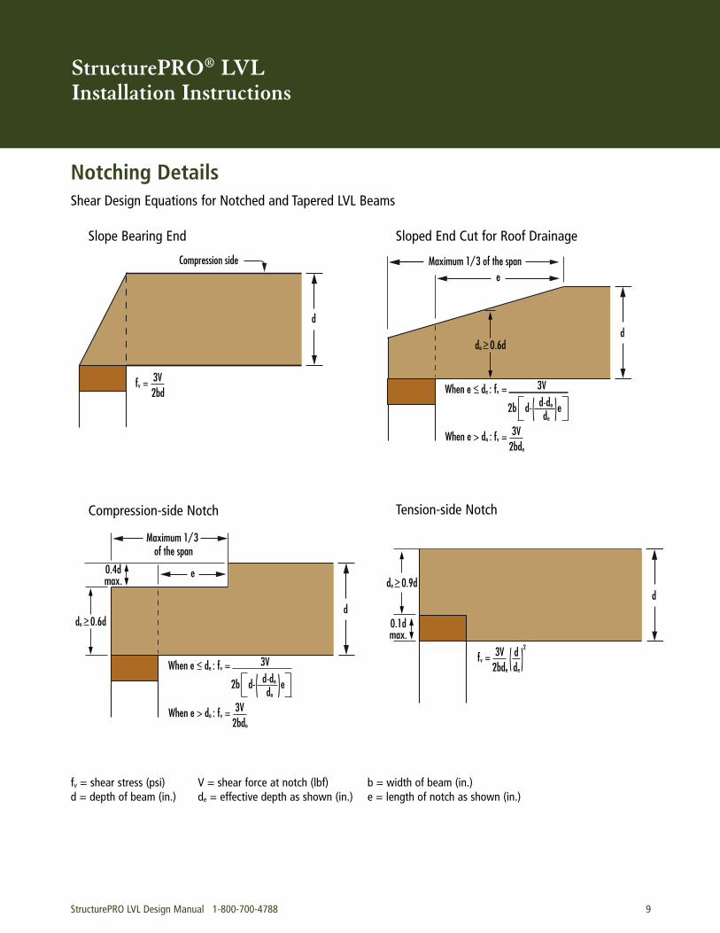
Notching DetailsShear Design Equations for Notched and Tapered LVL Beams
d
Compression side
fv = 3V 2bd
Slope Bearing End
When e < de : fv = 3V
2b d- d-de e
de
When e > de : fv = 3V 2bde
d
Maximum 1/3 of the spane
de > 0.6d
Sloped End Cut for Roof Drainage
d
Maximum 1/3 of the span
de > 0.6d
e0.4dmax.
When e < de : fv = 3V
2b d- d-de
e de
When e > de : fv = 3V 2bde
Compression-side Notch
d
fv = 3V 2bde
de > 0.9d
0.1dmax.
d 2
de
Tension-side Notch
fv = shear stress (psi) V = shear force at notch (lbf) b = width of beam (in.)d = depth of beam (in.) de = effective depth as shown (in.) e = length of notch as shown (in.)
StructurePRO® LVL Handling Instructions and Sizing Software
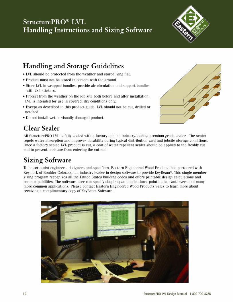
Handling and Storage Guidelines• LVL should be protected from the weather and stored lying flat.
• Product must not be stored in contact with the ground.
• Store LVL in wrapped bundles, provide air circulation and support bundleswith 2x4 stickers.
• Protect from the weather on the job site both before and after installation.LVL is intended for use in covered, dry conditions only.
• Except as described in this product guide, LVL should not be cut, drilled ornotched.
• Do not install wet or visually damaged product.
Clear SealerAll StructurePRO LVL is fully sealed with a factory applied industry-leading premium grade sealer. The sealerrepels water absorption and improves durability during typical distribution yard and jobsite storage conditions.Once a factory sealed LVL product is cut, a coat of water repellent sealer should be applied to the freshly cutend to prevent moisture from entering the cut end.
Sizing SoftwareTo better assist engineers, designers and specifiers, Eastern Engineered Wood Products has partnered withKeymark of Boulder Colorado, an industry leader in design software to provide KeyBeam®. This single membersizing program recognizes all the United States building codes and offers printable design calculations andbeam capabilities. The software user can specify simple span applications, point loads, cantilevers and manymore common applications. Please contact Eastern Engineered Wood Products Sales to learn more aboutreceiving a complimentary copy of KeyBeam Software.
10 StructurePRO LVL Design Manual 1-800-700-4788
StructurePRO® LVLTechnical Notes and Certifications
StructurePRO LVL Design Manual 1-800-700-4788 11
FSC® CertificationEastern Engineered Wood Products has achievedForestry Stewardship Council™ Chain of CustodyCertification. This certification ensures thatEastern’s customers have a verifiable connectionbetween their companies and certified manufactur-ers who adhere to the requirements of the FSCcertification program. StructurePRO LVL productsare available with this chain of custody certification.Builders who utilize products manufactured fromforests certified by FSC, with an intact chain ofcustody, can qualify for points in the US GreenBuilding Council’s LEED system, which is a third-party certification program and benchmark forthe design, construction, and operation of high-performance green buildings.
Technical SupportWhile supplying a superior product, we are also ded-icated to an unprecedented level of support to ourcustomers. We provide not only phone support, but abroad library of technical materials, bulletins andother relevant information for our products.
Our highly trained technical services staff, led byindustry veterans, combine their extensive knowl-edge and state-of-the-art tools to assist you with anydesign or construction question and provide full support for our design software.
Eastern Engineered Wood Products1245 Easton Road
Bethlehem, PA 18015800-700-4788484-853-3100
484-853-3830 (Fax)www.eewp.com
REV 02-12