composite elevated water storage tank … · composite elevated water storage tank ... • elevated...
TRANSCRIPT

COMPOSITE ELEVATED WATER STORAGE TANK
John Koch, P.E., DEEMay 4, 2007

Typical Water Storage Tanks In the Northwest
•• Ground Level Storage ReservoirsGround Level Storage Reservoirs•• StandpipesStandpipes•• Wood Stave TanksWood Stave Tanks•• Elevated Steel Storage ReservoirsElevated Steel Storage Reservoirs•• Elevated Composite ReservoirsElevated Composite Reservoirs

Steel Standpipes

Ground Storage Reservoirs
Prestressed ConcretePrestressed Concrete
LinedLined
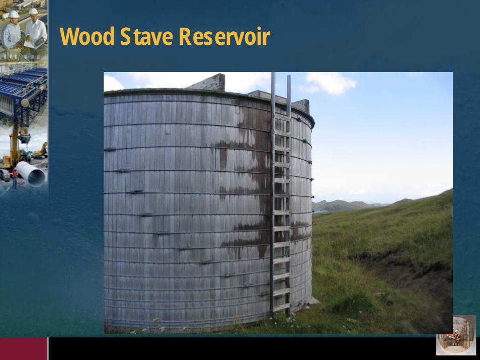
Wood Stave Reservoir

Elevated Steel Reservoirs

Elevated Composite Reservoirs

Why Chose Elevated Composite?
• Cost of Steel Has Escalated• Several Contractors Now Construct Composite Tanks
Making the Costs Competitive• All the Storage Volume is Useable• Reduced Maintenance Costs• Multi-use Potential of Space in Pedestal (Office -
Storage)

More Useable Volume
159 Ft159 Ft157 Ft 6 In157 Ft 6 In
2.5 MG2.5 MG
99 Ft99 Ft
0.94 MG0.94 MG
54 Ft54 Ft
104 Ft104 Ft
5555’’--66””

Design Considerations
•• Seismic RequirementsSeismic Requirements•• Air Gap For OverflowAir Gap For Overflow•• Supplemental DisinfectionSupplemental Disinfection•• SamplingSampling•• Circulation of ContentsCirculation of Contents•• SecuritySecurity

Seismic Loading Is A ConsiderationConcrete FoundationConcrete Foundation
Donut 35 Ft Inside Donut 35 Ft Inside 69 Ft Outside69 Ft Outside

What Makes the Tank Competitive
Reinforcing Steel Reinforcing Steel PrePre--assembledassembled
Prefabricated FormsPrefabricated Forms

Pre-Assembled Reinforcing Steel

Forms Move Up Only

Forming Top of Pedestal and Bottom of Reservoir

What is Next After the Concrete Work?

Where is The Steel Tank Constructed?
Set the Ring Beam SupportsSet the Ring Beam Supports
Rig and Beginning Welding the Rig and Beginning Welding the Cone Portion of the ReservoirCone Portion of the Reservoir

Certified Welding Inspector Should Be Part of Engineering Construction Team
Machine WeldsMachine Welds
Hand WeldsHand Welds
1 1 ¼”¼” PlatePlate

Welding From Inside As Well As Outside of Tank

Certified NACE Coating Inspector Should be Part of the Engineering Construction
Team

Day of Tank RaisingWind Less Than 5 MPH

Raising 455,000 Pounds in Under 4 Hours
First Jacking SequenceFirst Jacking Sequence Jacks and Cable AssembliesJacks and Cable Assemblies

Two Hours Into the Lifting Process

Tank in Final Position
Steel Plates Across Concrete HaunchesSteel Plates Across Concrete Haunches

Lifting CompletedLifting Completed

Tank Bottom Pressure Checked for Leaks

Repairing Leaks in Tank Bottom

Tank Bottom is Prepared for Grouting Voids
22”” Threaded CouplingsThreaded Couplingsat Approximately 8 Ft at Approximately 8 Ft Centers For Grout Centers For Grout

Grout Being Pumped Into Void Between Reservoir ¼” Plate Bottom and Concrete Roof On Pedestal
Grout Flowing into Next Grout Flowing into Next Grouting PortGrouting Port

Coating Inside of Tank
PainterPainter’’s Rail Inside Reservoirs Rail Inside Reservoir

Holiday Testing Interior Tank Coating

Inside Components of Reservoir
Access TubeAccess Tube
Overflow PipeOverflow Pipe
AccessAccess LadderLadder
Chlorine Injection Chlorine Injection or Sample Portor Sample Port

Completed Tank
Tank Tank AccessAccess
Center Tube Center Tube AccessAccess
Tank Tank Ventilation Ventilation
LouverLouver
FAA Clearance FAA Clearance LightLight

Air Gap For Overflow and Drainage Pipe
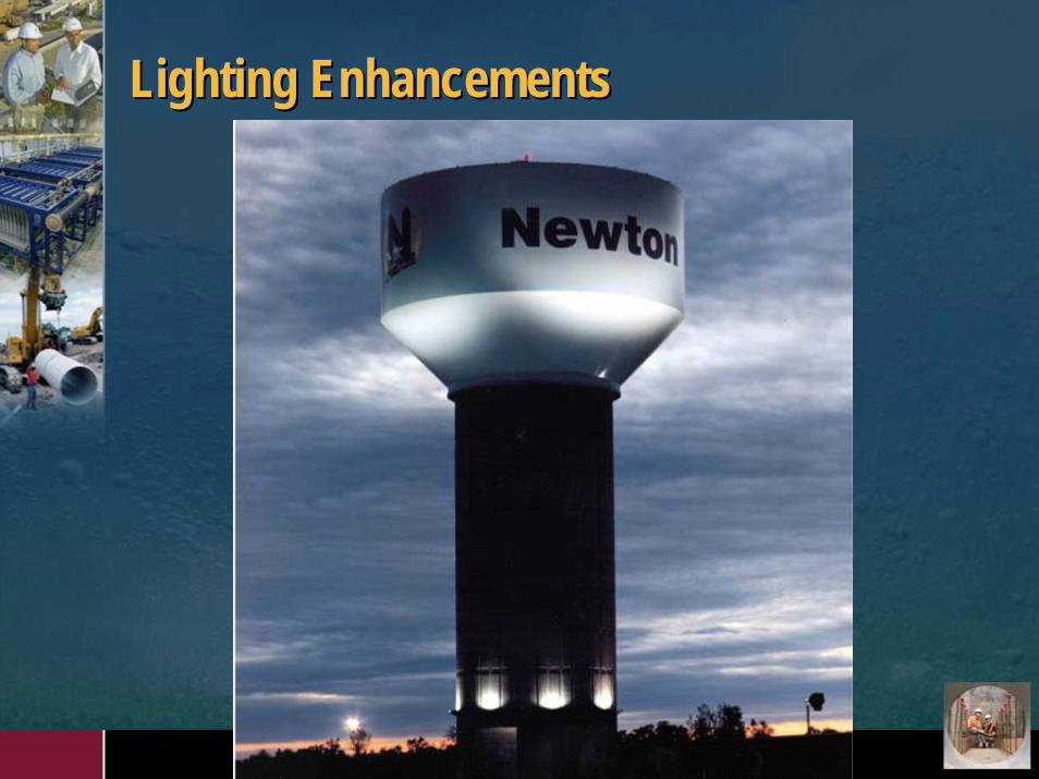
Lighting EnhancementsLighting Enhancements

Questions?
ContactContactJohn Koch John Koch Direct Line: 360 588360 588--70027002E-mail: [email protected]@hdrinc.com