composite hollow fiber membranes for post … library/research/coal...composite hollow fiber...
TRANSCRIPT
Composite Hollow Fiber Membranes for Post Combustion CO2 Capture
DOE Award: DE-FE0007514
Project Close Meeting
Paul Glaser Fred Stewart Bill Koros

Acknowledgment "The material described in the presentation is based upon work supported by the Department of Energy National energy Technology Laboratory (DOE-NETL) under award number DE-FE0007514."
Disclaimer “This presentation was prepared as an account of work sponsored by an agency of the United States Government. Neither the United States Government nor any agency thereof, nor any of their employees, makes any warranty, express or implied, or assumes any legal liability or responsibility for the accuracy, completeness, or usefulness of any information, apparatus, product, or process disclosed, or represents that its use would not infringe privately owned rights. Reference herein to any specific commercial product, process, or service by trade name, trademark, manufacturer, or otherwise does not necessarily constitute or imply its endorsement, recommendation, or favoring by the United States Government or any agency thereof. The views and opinions of authors expressed herein do not necessarily state or reflect those of the United States Government or any agency thereof.”

Project Goal & Team
• Hollow fiber fabrication & coating
• Module design
• Technical and economic feasibility analysis
• Polymer development
• Polymer property optimization
• Coating solution development
• Fiber coating process development
• Effect of fly ash on membranes
• Membrane performance validation in coal flue-gas
Develop bench-scale coated composite hollow fiber membrane materials and processes for CO2/N2 separation in coal flue-gas at least 90% CO2 capture with less than 35% increase in levelized cost of electricity
Membrane scale-up
Polymer synthesis
Fundamental studies
Performance validation

Project Team Members
• Teresa Grocela-Rocha
• Joe Suriano
• Paul Glaser
• David Moore
• Hongyi Zhou
• Pat McCloskey
• Surinder Singh
• Kristi Narang *
• Balajee Ananthasayanam
• Lauraine Denault
• Jeff Manke *
• Paul Wilson
• Paul Howson *
• Dhaval Bhandari (PI) *
• Chris Orme
• John Klaehn • Fred Stewart (PL) • Joshua McNally
• Ali Rownaghi • William Koros (PL) • Lucy Liu
• Jerrod Doss Isaak
• Tom Barton • Vijay Sethi (PL)

Summary
The team fabricated small-scale hollow fiber modules for the separation of CO2 from flue-gas streams.
Poly(phosphazene) materials were used in a selective layer in combination with a Torlon (polyamide-imide) porous support.
Significant difficulties involving performance degradation, both in permeance and in selectivity over time were identified and partially addressed using a variety of techniques, but significant barriers to implementing candidate materials in a robust system remain at the end of the award period.
Alternate routes towards increasingly robust systems and lines of further inquiry were identified for subsequent work. Technoeconomic and mechanical models were built to demonstrate the potential benefits of the overall approach if material challenges can be overcome.

Project BP-1 Scorecard (2012-2013)
BP-1 Deliverable BP-1 Status
CO2 selective polymer material with PCO2 = 200
Barrer, SCO2/N2 ≥ 30
Polyphosphazene materials synthesized with PCO2
= 100-500 Barrer, SCO2/N2 = 20-40
Fabricate high porosity hollow fiber (HF) supports
1 m strands of HF support fabricated with P/lCO2 > 20,000 GPU, surface pores ≈ 20-50 nm
Develop processes to fabricate defect-free
composite HF membranes
Batch, dip coating (lab-scale); roll-to-roll coating (bench-scale) processes developed. Defect-free
10” membrane modules fabricated.
Demonstrate stable performance under
realistic flue-gas conditions
Composite HF membrane module tested under
realistic flue-gas mixture. SCO2/N2 = 25-30, stability > 100 h, P/lCO2 < 50 GPU.
Preliminary techno-economic analysis study
Membrane systems model developed using Aspen Plus® & Aspen Custom Modeler®

Project BP-2 Scorecard (2013-2014)
BP-2 Deliverable BP-2 Status Scale-up polymer synthesis process
Polyphosphazene raw materials synthesized at 100 g scale with PCO2 = 100-500 Barrer, SCO2/N2 = 20-40
Scale-up HF support fabrication
50 m continuous spools of HF support fabricated with surface pore size ≈ 20-50 nm, P/lCO2 < 1,000 GPU
Scale-up composite HF membrane fabrication
Defect-free 10” membrane modules with initial SCO2/N2 ≥ 30 and P/lCO2 up to 1000 GPU fabricated.
Demonstrate stable performance under realistic flue-gas conditions
Membrane mini-modules with initial SCO2/N2 ≥ 30 and P/lCO2 up to 1000 GPU not stable >100 h testing Membrane mini-modules with SCO2/N2 ≥ 30 and 100 h stability low P/lCO2 < 50 GPU

Project Overview
Polymer composite hollow fiber membranes and processes for economical post-combustion CO2 capture from coal flue-gas

Membrane System Considerations
*Adapted from Merkel, Tim C., et al. "Power plant post-combustion carbon dioxide capture: An opportunity for membranes." Journal of Membrane Science 359.1 (2010): 126-139.
Schematic representation of a membrane process for CO2 removal from coal flue gas
• Various membrane process designs considered
• Two stage membrane process shortlisted for further investigation

Membrane Systems Considerations
Parameter Values
Membrane-I/Membrane-II Vacuum/air sweep
Flue gas composition DOE baseline case 11* CO2/N2/H2O/O2(vol.%)
13.53/68.08/15.17/2.40
Flue gas flow rate 540 m3/s
Flue gas pressure 1.2-3 Bar
Flue gas temperature 45 °C
Membrane Selectivity (CO2/N2) 30-80
Membrane Permeance 100-2500 GPU
Summary of economic model assumptions
*Cost and Performance Baseline for Fossil Energy Plants Volume 1: Bituminous Coal and Natural Gas to Electricity, Revision 2, November 2010.,DOE/NETL-2010/1397

Membranes Model Analysis
• Overall membrane area highly dependent on permeance and mildly on selectivity in the selected range
Sensitivity analysis of overall membrane area to permeance & selectivity*
*Assumptions – Counter/counter-current membranes, membrane-I pressure ratio = 10

Sensitivity analysis of membrane process CO2 purity to selectivity
Membranes Model Analysis
• Overall membrane process CO2 purity strongly dependent on selectivity *Assumptions - Counter/counter-current membranes, membrane-I pressure ratio = 10

Module Development Risk Analysis - Mechanical
Failure Mode
Risks
During Operation During Manufacturing
Gas Pressure
CTE
High Temperature Degradation
SOX, NOX, fly ash
degradation
Thermal cycling
Thermal Shock
Pressure Spikes
Residual Stresses
Leakage / Pinholes
Coating/ Intermediate Layer
Seals
Substrate
Pressure Vessel Housing / Flanges
N/A N/A
Module Joints N/A N/A
High
Medium
Low
Risk Probability
• Burst tests/tensile testing to estimate hollow fiber strength • Analytical (FEA analysis) to estimate effect of thermal & pressure
stresses • 200-hr flue gas (w/SO2, NOX) performance tests followed by post
testing evaluation

Poly(phosphazene) Materials for CO2 separation
Film forming
Crosslinking
Strong CO2 interaction
General structure of stabilized (methoxyethoxy) ethanol phosphazene (MEEP)
* L. M. Robeson, The Upper Bound Revisited. J. Membr. Sci. 2008, 320, 390 +C.J. Orme, M.K. Harrup, T.A. Luther, R.P. Lash, K.S. Houston, D.H. Weinkauf, F.F. Stewart, Characterization of gas transport in selected rubbery amorphous polyphosphazene membranes, J. Membr. Sci. 186 (2001) 249
Permeability-selectivity plot for CO2/N2 gas pair
MEEP Polyphosphazene polymers provide CO2 affinity, permeability, and tunability for coating
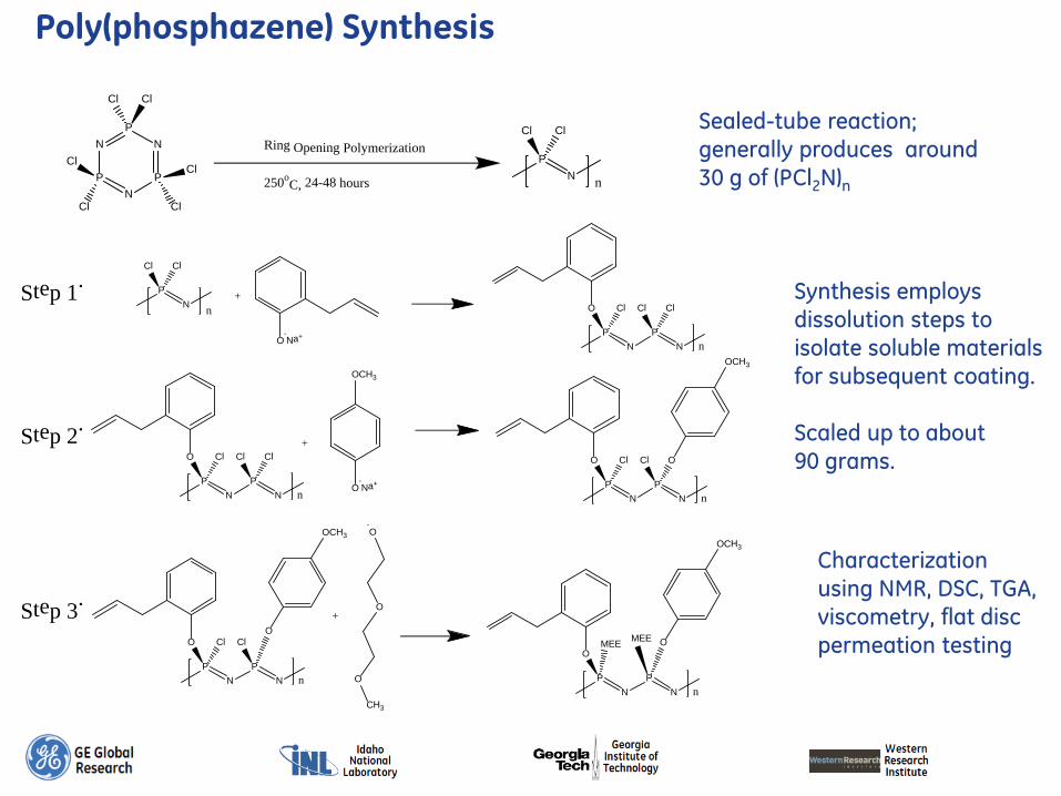
Poly(phosphazene) Synthesis
PN
Cl Cl
n
O-Na+
+
PN
P
O Cl
nN
ClClStep
1.
O-Na+
+Step 2.
OCH3
PN
P
O Cl
nN
OCl
OCH3
PN
P
O Cl
nN
ClCl
PN
P
O Cl
nN
OCl
PN
P
OMEE
nN
OMEE
OCH3OCH3
Step 3.
CH3
O
O
-O
+
PN
PN
P
N
ClCl
Cl
ClCl
Cl
Ring Opening Polymerization
250oC, 24-48 hours
PN
Cl Cl
n
Sealed-tube reaction; generally produces around 30 g of (PCl2N)n
Synthesis employs dissolution steps to isolate soluble materials for subsequent coating. Scaled up to about 90 grams.
Characterization using NMR, DSC, TGA, viscometry, flat disc permeation testing

Poly(phosphazene) Coating Development
Compatibility • Solubility in
solvents benign to HF supports
Properties
• Improve physical handling
• High MW to reduce support infiltration
Performance
• Achieve target permeability and selectivity
• Long term stability
Cross-linking
• Maintain dimensional integrity
Permeability-selectivity plot for CO2/N2 at 30 °C (Pure gas-Flat sheet))
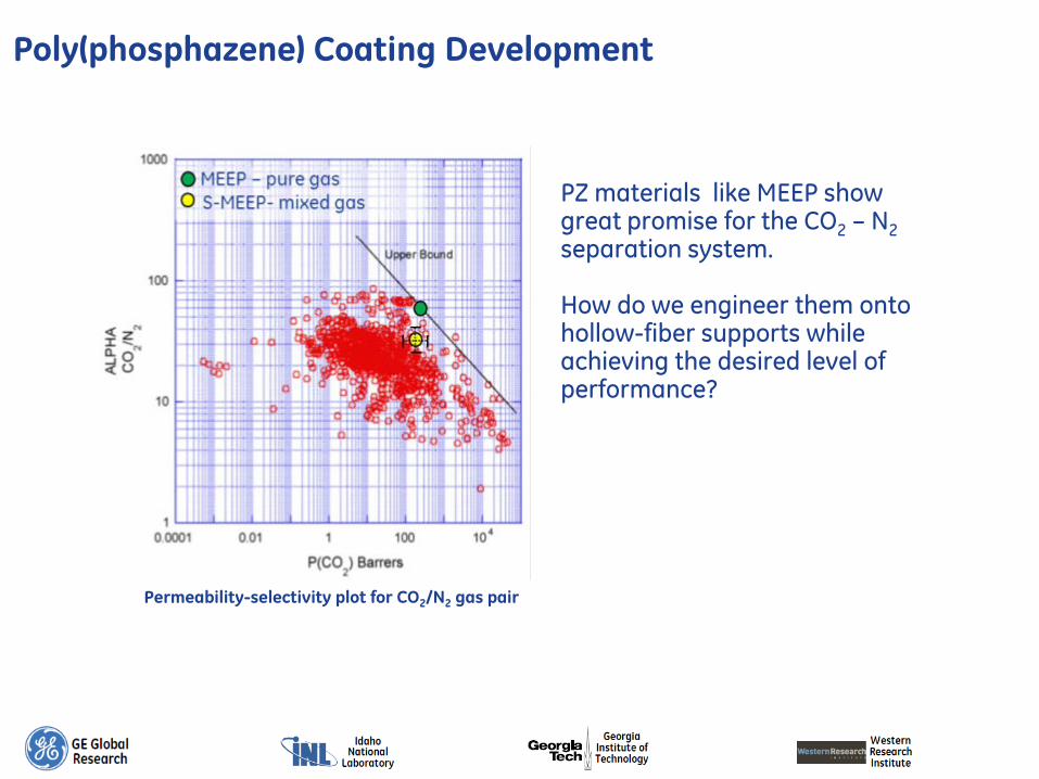
PZ materials like MEEP show great promise for the CO2 – N2 separation system. How do we engineer them onto hollow-fiber supports while achieving the desired level of performance?
Permeability-selectivity plot for CO2/N2 gas pair
Poly(phosphazene) Coating Development
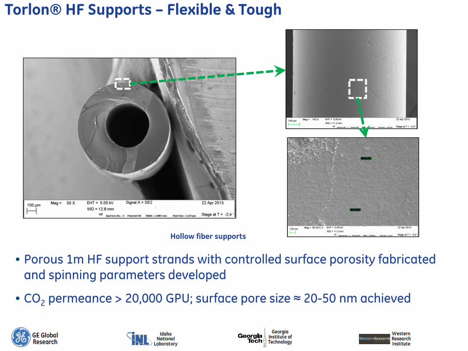
Torlon® HF Supports – Flexible & Tough
• Porous 1m HF support strands with controlled surface porosity fabricated and spinning parameters developed
• CO2 permeance > 20,000 GPU; surface pore size ≈ 20-50 nm achieved
Hollow fiber supports

Coating PZ on Hollow Fibers
Defect Free Hollow fiber support 2-layer composite
Porous support maintains high flux
Thin, crosslinked layer provides selectivity and flux.
Must be stable over time.
PZ coating infiltrates porous support
Solvent system degrades support
Flux attenuated
Layer is not defect-free. PZ coating does not provide selectivity
PZ solution

Using PDMS as a “caulking” layer
Crosslinked PZ coating provides affords three-layer composite membrane
Porous polymer “primed” with PDMS coating
Hollow fiber PDMS
solution
Steps are intended to maintain, but not recover lost permeance / flux
High permeance, no real selectivity
PZ solution +
crosslinking

Composite Hollow Fiber Morphology
Lumen Hollow Fiber
Support
Lumen
Coating Layer
Composite hollow fiber membrane prepared on 10cm scale

Polyphosphazene Cross-Linking
The allylphenol group is responsible for crosslinkning the polymer. Thermal free-radical initiators such as AIBN and benzoyl peroxide were used in the course of the project. The initiators are mixed with the polymer solution, coated on to hollow fibers, and heated.

Effect of cross-linking time on polyphosphazene flat sheet permeability and selectivity
Poly(phosphazene) separation performance was found to be related to crosslinking phenomena.
Poly(phosphazene) Cross-Linking

HF membrane module performance testing at WRI under realistic flue gas conditions
Composite HF Membrane Module Testing
• Composite HF membrane modules with high cross-link density showed SelectivityCO2/N2 ≥ 30 and >100 h stability, but with low permeanceCO2 ≈ 1-2 GPU

HF membrane module performance testing at GE under simulated flue gas conditions
Composite HF Membrane Module Testing
• Composite HF membrane modules with lower cross-link density showed initial SelectivityCO2/N2 ≥ 30 with permeanceCO2 up to 1000 GPU, but poor stability over 100 h testing

Factors affecting performance
Effect of crosslinking time: in this study, CO2 permeance increased, but selectivity dropped precipitously
Different PZ coating techniques (pre-crosslinking, in this case) were not effective
Challenges encountered in producing robust modules
A series of experiments including - different initiators, - cure conditions, - pre-crosslinking of PZ - post-treatments - solvents - different polymer batches - fiber repair methods was conducted.
Conditions were not identified which provided robust permeance & selectivity values in HF modules approaching target values
Degradation over time was observed in many cases.
Ethanol, a preferred solvent for casting PZ films had a deleterious effect on porous Torlon. Demonstrated by depressing the onset of a sub-Tg transition.
Even though Torlon is remarkably solvent-resistant and tough, the porous structure is susceptible to degradation. The PDMS coating may delay, but may not prevent PZ migration over time into a porous polymeric support, driving unpredictable performance

Performance loss over time – a hypothesis
PZ coating provides affords three-layer composite membrane
Porous polymer “primed” with
PDMS Hollow fiber
PDMS solution
PZ solution +
crosslinking
High permeance, no selectivity
Time

Hollow Fiber Support Fabrication

Composite Hollow Fiber Fabrication

Linear Dip Coating Process

Continuous ‘Roll-to-Roll’ Coating Process
Continuous ‘roll-to-roll’ coating process

Scale up of hollow fibers at GRC
After spinning, hollow fibers are solvent-exchanged with a series of increasingly non-polar solvents to remove bore fluids and generate porosity
On <1 m scale, this is easily handled with a batch operation.
Solvent exchanging full “lassos” proved to be more difficult.

Spin 17 Water exchange
Tank Drainage and Recirculating water out
Recirculating water in
• Fibers spun • Several 2 m strands cut from the beginning
of each state from winder spool • Remaining fiber removed from spool as
continuous lasso (20-50 m) • Lasso laid in bttm of water tank • Tank filled with ~ 10 gallons DI water • Water recirculated in tank, heated to 40 oC • Water held in tank for 1 day at these
conditions • After 1 day, water drained from the bottom
of the tank (~ 15 min) • Tank refilled and process repeated for 7
additional days (total 8 days)
40 oC

Continuous water circulation & heating solvent exchange
setup
• Poor solvent exchange of NMP residual solvent in stationery water presumed
• Solvent exchange protocol modified to improve the mass transfer rate. Continuous circulation of water and keep the water warm (40 °C) during day time, heat and circulation during night
• Better leaching of solvent and additives observed during modified solvent exchange. After day 3, water quality remained visibly unchanged
Water Solvent exchange – Day 1
Water Solvent exchange – Day 2
Water Solvent exchange – Day 3
Solvent Exchange (Spin 17)

Solvent exchange at scale – H2O to CH3OH to Hexane
Water drained from tank
• Water drained from tank, lasso remains in bottom of tank
• Tank filled with ~ 4 gallons methanol • Soak for ~ ½ day (3-4 hours) • Drain methanol from tank • Tank filled with ~ 4 gallons hexane • Soak for ~ ½ day (3-4 hours) • Drain hexane from tank
• Lasso removed from tank • Laid out to air dry overnight • Fibers transferred to convection oven to dry
at 180 oC for 3 days, air atm

ARS8-2 (10,189 GPU) ARS8-8 (13,781 GPU) ARS8-7 (17,250 GPU)
ARS8-3 (19,782 GPU) ARS8-1 (21,000 GPU) ARS8-4 (24,294 GPU)
GaTech Spin 8 – Fibers Comparison (Increasing Permeance Order)
State-1 (38 GPU)
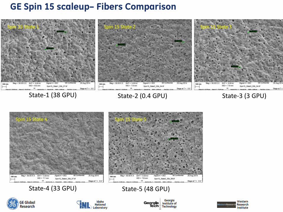
GE Spin 15 scaleup– Fibers Comparison
State-2 (0.4 GPU) State-3 (3 GPU)
State-4 (33 GPU) State-5 (48 GPU)
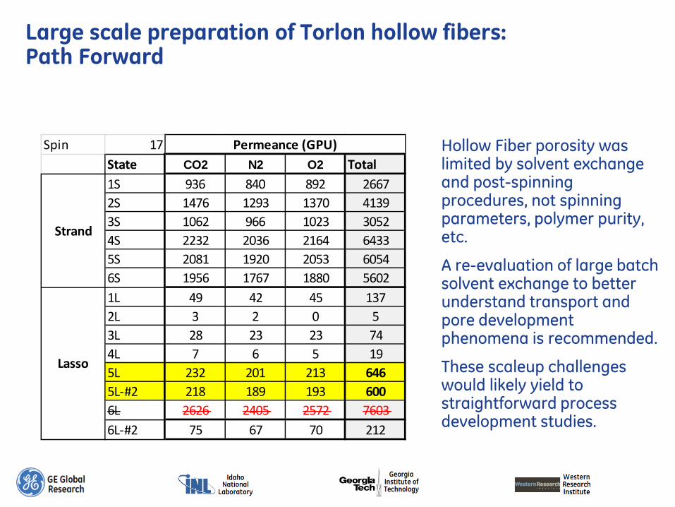
Large scale preparation of Torlon hollow fibers: Path Forward
Spin 17State CO2 N2 O2 Total1S 936 840 892 26672S 1476 1293 1370 41393S 1062 966 1023 30524S 2232 2036 2164 64335S 2081 1920 2053 60546S 1956 1767 1880 56021L 49 42 45 1372L 3 2 0 53L 28 23 23 744L 7 6 5 195L 232 201 213 6465L-#2 218 189 193 6006L 2626 2405 2572 76036L-#2 75 67 70 212
Strand
Lasso
Permeance (GPU) Hollow Fiber porosity was limited by solvent exchange and post-spinning procedures, not spinning parameters, polymer purity, etc.
A re-evaluation of large batch solvent exchange to better understand transport and pore development phenomena is recommended.
These scaleup challenges would likely yield to straightforward process development studies.
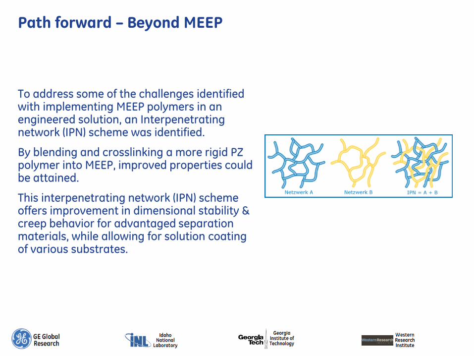
Path forward – Beyond MEEP
To address some of the challenges identified with implementing MEEP polymers in an engineered solution, an Interpenetrating network (IPN) scheme was identified.
By blending and crosslinking a more rigid PZ polymer into MEEP, improved properties could be attained.
This interpenetrating network (IPN) scheme offers improvement in dimensional stability & creep behavior for advantaged separation materials, while allowing for solution coating of various substrates.

Polymer 1: 80% MEEP
Polymer 2: PPOP
Crosslinkable (2-AP) groups Mix &
Crosslink
Polymer 1 crosslinks Polymer 2 crosslinks
P
N n
X, Y, or Z X, Y, or Z
OX =
O OCH3Y =
Z = O
OOX:Y:Z
= 5:15:80
2-AP
P
N n
X or Y X
or Y OX =
OY =
X:Y =
1:99
2-AP
Path forward : MEEP/PPOP IPN

Path forward – Initial proof of IPN concept
Membrane Temperature (⁰C) CO2 Permeability (Barrers)
CO2/N2 Selectivity
IPN 3
70 % (80 % MEEP) / 30 % PPOP
30 458.6 35.8
60 661.6 20.4
10
100
1 10 100 1000 104 105
Sele
ctiv
ity C
O2/N
2
CO2 Permeability (Barrers)
100 % MEEP
70 % IPN50 % IPN
Upper Bound
74 % MEEP
48 % MEEP
30 % IPN
60 oC Data
All IPNs formed from 80 % MEEP
80 % MEEP
PerformanceTarget
Initial results show good performance with 100h stability on disc substrates
Smooth, hard surfaces with little tack
Implementation on HF systems would require solvent optimization, processing studies etc.

Final Thoughts
Important interactions between materials & processes needed to construct an advantaged composite HF system for CO2 separation were uncovered through this work. The importance of testing systems long enough to measure slow changes was made clear.
These interactions would not be readily predictable from examining the components a priori (polymer, support, process)
The team and its members can offer informed guidance for future work in this area to address these risks as part of large or focused programs.