composite insulators for medium voltage … · coating test). - iec 60383-2. insulators for...
TRANSCRIPT
GLOBAL STANDARD Page 1 of 44
COMPOSITE INSULATORS FOR MEDIUM VOLTAGELINES
GSCC010
Rev. 00
5/12/2017
This document is intellectual property of ENEL Group distribution companies; reproduction or distribution of
its contents in any way or by any means whatsoever is subject to the prior approval of the above mentioned
companies which will safeguard their rights under the civil and penal codes.
COMPOSITE INSULATORS FOR MEDIUM VOLTAGE LINES
Revision Data List of modifications
00 17/11/2017 First emission
Countries’ I&N Elaborated by
Argentina Roberto De Antoni
Brazil Vanderlei Robadey Carvalho
Chile Daniel Alejandro Gonzalez Sarkis
Colombia Juan carlos Gómez Cubillos
Italy Luca Giansante
Peru Roberto Sanchez Vargas
Romania Vasilica Obrejan
Spain Juan Gonzalez Lara
Elaborated by Verified by Approved by
Global I&N – O&M/NCSM Carmen Esteban
SantamariaNicola Cammalleri Fabio Giammanco
GLOBAL STANDARD Page 2 of 44
COMPOSITE INSULATORS FOR MEDIUM VOLTAGELINES
GSCC010
Rev. 00
5/12/2017
INDEX
1 SCOPE............................................................................................................................................................................... 6
2 REFERENCE LAWS AND STANDARDS...................................................................................................................... 6
2.1 Laws .................................................................................................................................................................. 6
2.2 Standards .......................................................................................................................................................... 7
2.3 Local standards.................................................................................................................................................. 8
3 SERVICE CONDITIONS ................................................................................................................................................. 8
3.1 Specific service conditions for Colombia............................................................................................................ 9
4 DEFINITIONS.................................................................................................................................................................. 9
4.1 Insulator............................................................................................................................................................ 9
4.2 Composite insulator .......................................................................................................................................... 9
4.3 String insulator unit........................................................................................................................................... 9
4.4 Line post insulator............................................................................................................................................. 9
4.5 Creepage distance ............................................................................................................................................. 9
4.6 Arcing distance.................................................................................................................................................. 9
5 TECHNICAL REQUIREMENTS..................................................................................................................................... 9
5.1 Mechanical Load................................................................................................................................................ 9
5.1.1 String insulators: Specific Mechanical Load (SML)...................................................................................... 9
5.1.2 Line Post insulator....................................................................................................................................10
5.2 Electrical requirements.....................................................................................................................................10
5.2.1 Standardized insulation levels ..................................................................................................................10
GLOBAL STANDARD Page 3 of 44
COMPOSITE INSULATORS FOR MEDIUM VOLTAGELINES
GSCC010
Rev. 00
5/12/2017
5.2.2 Creepage distance and arcing distance.....................................................................................................11
5.3 Other dimensions.............................................................................................................................................11
5.3.1 Total length .............................................................................................................................................11
5.3.2 String insulators: Maximum diameter.......................................................................................................11
6 DESIGNATION..............................................................................................................................................................11
6.1 String insulators ...............................................................................................................................................11
6.2 Line post insulators ..........................................................................................................................................12
6.3 Designation Example........................................................................................................................................12
7 CONSTRUCTION CHARACTERISTICS .....................................................................................................................12
7.1 Construction.....................................................................................................................................................12
7.1.1 Dielectric Insulator Core .........................................................................................................................12
7.1.2 Hydrophobic insulation housing ...............................................................................................................13
7.1.3 Fittings.....................................................................................................................................................14
7.2 Quality issues ...................................................................................................................................................15
8 MARKING ......................................................................................................................................................................15
9 TESTING ........................................................................................................................................................................16
9.1.1 Design Tests.............................................................................................................................................16
9.1.2 Type tests ................................................................................................................................................19
9.1.3 Sample tests ............................................................................................................................................19
9.1.4 Routine tests............................................................................................................................................20
10 TECHNICAL CONFORMITY ASSESSMENT..............................................................................................................21
10.1 Local Certifications.......................................................................................................................................21
11 GUARANTEE.................................................................................................................................................................21

GLOBAL STANDARD Page 4 of 44
COMPOSITE INSULATORS FOR MEDIUM VOLTAGELINES
GSCC010
Rev. 00
5/12/2017
12 CONDITIONS OF SUPPLY...........................................................................................................................................21
13 ANNEX A- LIST OF COMPONENTS...........................................................................................................................22
13.1 List of components, String insulators ...........................................................................................................22
13.1.1 String insulators, main characteristics..................................................................................................23
13.2 List of components, Line post insulators ......................................................................................................24
13.2.1 Line post insulators, main characteristics.............................................................................................25
14 ANNEX B- LOCAL SECTIONS .....................................................................................................................................26
14.1 E-DISTRIBUZIONE-ITALIA, E-DISTRIBUȚIE BANAT, E-DISTRIBUȚIE DOBROGEA, E-DISTRIBUȚIE MUNTENIA ...26
14.1.1 Replaced Local standards:....................................................................................................................26
14.1.2 Detail for end fittings from string insulators:........................................................................................26
14.1.3 Detail for line post insulators GSCC010/16...........................................................................................27
14.2 Supply..........................................................................................................................................................28
14.3 ENDESA DISTRIBUCIÓN ELÉCTRICA- SPAIN...................................................................................................29
14.3.1 Related Local standards:......................................................................................................................29
14.3.2 Marking...............................................................................................................................................29
14.3.3 Detail for end fittings from string insulators:........................................................................................29
14.3.4 Additional comment for GSCC010/05 (country code 530699)...............................................................29
14.3.5 Additional design requirements for GSCC010/11 (country code 300020)..............................................29
14.3.6 Details code GSCC010/19, country code 300043..................................................................................30
14.4 ENEL DISTRIBUCION COLOMBIA, ENEL DISTRIBUCION PERÚ, ENEL DISTRIBUCION CHILE, ENEL DISTRIBUCAO
RIO, ENEL DISTRIBUCAO CEARÁ, ENEL DISTRIBUCAO GOIAS......................................................................................32
14.4.1 Related Local standards:......................................................................................................................32
14.4.2 String insulator details.........................................................................................................................32
14.4.3 Line post insulator details....................................................................................................................33
15 ANNEX C - TECHNICAL CHECK LIST .......................................................................................................................42
15.1 String insulators...........................................................................................................................................42
GLOBAL STANDARD Page 5 of 44
COMPOSITE INSULATORS FOR MEDIUM VOLTAGELINES
GSCC010
Rev. 00
5/12/2017
15.2 Line post insulators......................................................................................................................................43
15.3 Example for GSCC010/02 .............................................................................................................................44
16 ANNEX D - STANDARDIZED DESIGNATION TO CREATE NEW CODES ...........................................................44
GLOBAL STANDARD Page 6 of 44
COMPOSITE INSULATORS FOR MEDIUM VOLTAGELINES
GSCC010
Rev. 00
5/12/2017
1 SCOPE
The aim of this document is to provide technical requirements for the supply of MV composite insulators to
be used in the MV lines of the distribution networks of Enel Group Distribution Companies, listed below:
Enel Distribución Colombia Colombia
Enel Distribución Peru Perú
Edesur Argentina
E-distributie Banat Romania
E-distributie Dobrogea Romania
E-distributie Muntenia Romania
E-distribuzione Italy
Endesa Distribución Eléctrica Spain
Enel Distribución Chile Chile
Enel Distribuição Ceará Brazil
Enel Distribuição Rio Brazil
Enel Distribuição Goiás Brazil
This document specifies the characteristics and tests that must be accomplished by the composite insulators
used in the medium voltage distribution network.
Additional prescriptions or integration of the main common part are reported in Local Sections with the same
corresponding clause or sub-clause number.
The local standards replaced by this standard appear in the local section.
2 REFERENCE LAWS AND STANDARDS
The list of reference laws and standards are mentioned below in this document.
2.1 Laws
Brazil
NR-10 - Segurança em Instalações e Serviços em Eletricidade
Chile
NSEG5. E.n.71 Reglamento de Instalaciones Eléctricas de Corrientes Fuertes.
Colombia
RETIE, Reglamento Técnico de Instalaciones Eléctricas.
Peru
Código Nacional de Electricidad – Suministro 2011.
Romania
GLOBAL STANDARD Page 7 of 44
COMPOSITE INSULATORS FOR MEDIUM VOLTAGELINES
GSCC010
Rev. 00
5/12/2017
NTE 001/03/00 – Normativ privind alegerea izolației, coordonarea izolației și protecția instalațiilor
electroenergetice împotriva supratensiunilor
NTE 003/04/00 – Normativ pentru construcția liniilor electrice aeriene de energie electrică cu
tensiuni peste 1000 V
Spain
R.D. 614/2001, de 8 de junio, sobre disposiciones mínimas para la protección de la salud y
seguridad de los trabajadores frente al riesgo eléctrico.
R.D. 337/2014, de 9 de mayo, por el que se aprueban el Reglamento sobre condiciones
técnicas y garantías de seguridad en instalaciones eléctricas de alta tensión y sus Instrucciones
Técnicas Complementarias ITC-RAT 01 a 23.
R.D. 223/2008, de 15 de febrero, por el que se aprueban el Reglamento sobre condiciones
técnicas y garantías de seguridad en líneas eléctricas de alta tensión y sus instrucciones
técnicas complementarias ITC-LAT 01 a 09.
2.2 Standards
The following standards are needful for the application of this Global Standard.
- CIGRE 33-204. Considerations on the design of composite suspension insulators based on
experience from natural ageing testing and electric field calculations.
- IEC 60071-1. Insulation co-ordination - Part 1: Definitions, principles and rules.
- IEC 60071-2. Insulation co-ordination - Part 2: Application guide.
- IEC 60383-1. Insulators for overhead lines with a nominal voltage above 1000 V - Part 1: Ceramic or
glass insulator units for a.c. systems - Definitions, test methods and acceptance criteria. (Zinc
Coating Test).
- IEC 60383-2. Insulators for overhead lines with a nominal voltage above 1000 V - Part 2: Insulator
strings and insulator sets for a.c. systems – Def, test methods and acceptance criteria.
- IEC 60587. Electrical insulating materials used under severe ambient conditions - Test methods for
evaluating resistance to tracking and erosion.
- IEC 60695-11-10. Fire hazard testing - Part 11-10: Test flames - 50 W horizontal and vertical flame
test methods.
- IEC 60815-1. Selection and dimensioning of high-voltage insulators intended for use in polluted
conditions - Part 1: Definitions, information and general principles.
- IEC 60815-3. Selection and dimensioning of high-voltage insulators intended for use in polluted
conditions - Part 3: Polymer insulators for a.c. systems.
- IEC 61109. Insulators for overhead lines - Composite suspension and tension insulators for a.c.
systems with a nominal voltage greater than 1 000 V - Definitions, test methods and acceptance
criteria.
GLOBAL STANDARD Page 8 of 44
COMPOSITE INSULATORS FOR MEDIUM VOLTAGELINES
GSCC010
Rev. 00
5/12/2017
- IEC 61621. Dry, solid insulating materials - Resistance test to high-voltage, low-current arc
discharges.
- IEC 61466 -1. Composite string insulator units for overhead lines with a nominal voltage greater than
1000 V - Part 1: Standard strength classes and end fittings.
- IEC 61466 -2. Composite string insulator units for overhead lines with a nominal voltage greater than
1000 V - Part 2: Dimensional and electrical characteristics.
- IEC 61952. Insulators for overhead lines - Composite line post insulators for A.C. systems with a
nominal voltage greater than 1 000 V - Definitions, test methods and acceptance criteria
- IEC 62631. Dielectric and resistive properties of solid insulating materials.
- IEC TS 62073. Technical Specification: Guidance on the measurement of wettability of insulator
surfaces.
- IEC 62217. Polymeric HV insulators for indoor and outdoor use - General definitions, test methods
and acceptance criteria.
- ISO 1461. Hot dip galvanized coatings on fabricated iron and steel articles -- Specifications and test
methods.
- ISO 34-1. Rubber, vulcanized or thermoplastic -- Determination of tear strength -- Part 1: Trouser,
angle and crescent test pieces.
- ISO 37. Rubber, vulcanised or thermoplastic. Determination of tensile stress-strain properties
- ISO 868. Plastics and ebonite - Determination of indentation hardness by means of a durometer
(Shore hardness)
- ISO 1183-1. Plastics - Methods for determining the density of non-cellular plastics - Part 1:
Immersion method, liquid pyknometer method and titration method
- IEC/TR 62662 Guidance for production, testing and diagnostics of polymer insulators with respect to
brittle fracture of core materials (and its Spanish transposition to UNE-CLC/TR62662 IN)
2.3 Local standards
See local section
3 SERVICE CONDITIONS
The service conditions to be considered for the material included in this standard are:
- Maximum Ambient Air Temperature: + 50 ºC.
- Minimum Ambient Air Temperature: - 40 ºC.
- Maximum relative humidity: 95%. For higher values see IEC 60071-1 and IEC 60071-2.
- Maximum altitude above mean sea level: 1.000 m (*). For higher values see IEC 60071-1 and IEC
60071-2
- Maximum solar radiation: 1.000 W/m2
GLOBAL STANDARD Page 9 of 44
COMPOSITE INSULATORS FOR MEDIUM VOLTAGELINES
GSCC010
Rev. 00
5/12/2017
Note: Insulation capacity depends on these service conditions, it can be considered the selection of a Um value equal to
or higher than the expected level for the nominal voltage when the equipment has to be installed at an altitude
higher than 1.000 m in order to compensate the decrease of withstand voltage of the external insulation.
3.1 Specific service conditions for Colombia
The reference altitude is 2.700 m.
4 DEFINITIONS
4.1 Insulator
Device designed to support and insulate a conductive element.
4.2 Composite insulator
Insulator made of at least two insulating parts, namely a core and a housing equipped with end fittings.
Composite insulators, for example, can consist either of individual sheds mounted on the core, with or
without an intermediate sheath, or alternatively, of a housing directly moulded or cast in one or several
pieces onto the core.
4.3 String insulator unit
Insulator of which the end fittings are suitable for flexible attachment to other similar string insulator units or
to connecting accessories.
4.4 Line post insulator
Rigid insulator intended to be subjected to cantilever, tensile and compressive loads, constructed with one or
more insulating materials and assembled on a metal base that is intended to be mounted rigidly on a
supporting structure.
4.5 Creepage distance
Shortest distance through the insulator surface between conductive parts of both sides of the insulator which
support the service voltage.
4.6 Arcing distance
Shortest distance in the air between conductive parts of both sides of the insulator which support the service
voltage.
5 TECHNICAL REQUIREMENTS
5.1 Mechanical Load
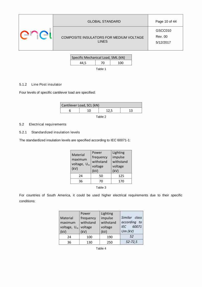
5.1.1 String insulators: Specific Mechanical Load (SML)
Three levels of specific mechanical load are specified:
GLOBAL STANDARD Page 10 of 44
COMPOSITE INSULATORS FOR MEDIUM VOLTAGELINES
GSCC010
Rev. 00
5/12/2017
Specific Mechanical Load, SML (kN)
44,5 70 100
Table 1
5.1.2 Line Post insulator
Four levels of specific cantilever load are specified:
Cantilever Load, SCL (kN)
6 10 12,5 13
Table 2
5.2 Electrical requirements
5.2.1 Standardized insulation levels
The standardized insulation levels are specified according to IEC 60071-1:
Materialmaximumvoltage, Um
(kV)
Powerfrequencywithstandvoltage(kV)
Lightingimpulsewithstandvoltage(kV)
24 50 125
36 70 170
Table 3
For countries of South America, it could be used higher electrical requirements due to their specific
conditions:
Materialmaximumvoltage, Um
(kV)
Powerfrequencywithstandvoltage(kV)
Lightingimpulsewithstandvoltage(kV)
Similar classaccording toIEC 60071Um (kV)
24 100 190 52
36 130 250 52-72,5
Table 4
GLOBAL STANDARD Page 11 of 44
COMPOSITE INSULATORS FOR MEDIUM VOLTAGELINES
GSCC010
Rev. 00
5/12/2017
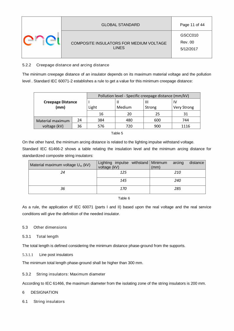
5.2.2 Creepage distance and arcing distance
The minimum creepage distance of an insulator depends on its maximum material voltage and the pollution
level . Standard IEC 60071-2 establishes a rule to get a value for this minimum creepage distance:
Creepage Distance(mm)
Pollution level - Specific creepage distance (mm/kV)
ILight
IIMedium
IIIStrong
IVVery Strong
16 20 25 31
Material maximumvoltage (kV)
24 384 480 600 744
36 576 720 900 1116
Table 5
On the other hand, the minimum arcing distance is related to the lighting impulse withstand voltage.
Standard IEC 61466-2 shows a table relating the insulation level and the minimum arcing distance for
standardized composite string insulators:
Material maximum voltage Um (kV)Lighting impulse withstandvoltage (kV)
Minimum arcing distance(mm)
24 125 210
145 240
36 170 285
Table 6
As a rule, the application of IEC 60071 (parts I and II) based upon the real voltage and the real service
conditions will give the definition of the needed insulator.
5.3 Other dimensions
5.3.1 Total length
The total length is defined considering the minimum distance phase-ground from the supports.
5.3.1.1 Line post insulators
The minimum total length phase-ground shall be higher than 300 mm.
5.3.2 String insulators: Maximum diameter
According to IEC 61466, the maximum diameter from the isolating zone of the string insulators is 200 mm.
6 DESIGNATION
6.1 String insulators
GLOBAL STANDARD Page 12 of 44
COMPOSITE INSULATORS FOR MEDIUM VOLTAGELINES
GSCC010
Rev. 00
5/12/2017
The string insulators are designated as follows (see IEC 61466-1 and 2):
- Letters CS
- Specific Mechanic Load in kN
- Two letters representing both end fittings, first one for the insulator upper side.
- Two numbers separated by a slash, the first one represents the lighting impulse withstand voltage in
kV and the second one the minimum creepage distance in mm
- A dash followed by the total length in mm (this last information doesn’t appear in the IEC 61466)
6.2 Line post insulators
Line post insulators are designated as follows:
- Letters CLP
- Specific Cantilever Load in kN followed by dash.
- Two numbers separated by a slash, the first one represents the lighting impulse withstand voltage in
kV and the second one the minimum creepage distance in mm
6.3 Designation Example
CS 70 EB 125/600-455
Composite string insulator, Specific mechanic load equal to 70 kN, with an eye for the support-side and a ball
for the conductor side, lighting impulse withstand voltage equal to125 kV and minimum creepage distance of
600 mm. Total length equal to 455 mm.
7 CONSTRUCTION CHARACTERISTICS
7.1 Construction
There are three important parts in an insulator:
- Dielectric Insulator Core
- Hydrophobic insulation housing
- Fittings
The insulator shall be designed and assembled to ensure that no moisture, water or external substances
reach the core.
7.1.1 Dielectric Insulator Core
It transmits the mechanical stresses produced by conductors to the support and provides the necessary
electrical insulation.
GLOBAL STANDARD Page 13 of 44
COMPOSITE INSULATORS FOR MEDIUM VOLTAGELINES
GSCC010
Rev. 00
5/12/2017
7.1.1.1 Material
Epoxy resin resistant to hydrolisys reinforced with glass fiber resistant to corrosion in order to prevent the risk
of brittle fractures.
7.1.2 Hydrophobic insulation housing
The hydrophobic insulation housing (sheath and sheds) protects the core from external agents providing
sealing and preventing the formation of a continuous film of water. The hydrophobic insulation housing
minimum thickness is 3mm. The housing provides the necessary creepage distance in order to get the
required insulation of the core surface.
In order to facilitate the integration with the environment the colour of the silicone-rubber shall be gray. Other
different colour shall be approved by Enel.
7.1.2.1 Material
Sheath and sheds shall be silicone-rubber (VMQ - Vinyl-Methyl-Polysiloxane, with filler additives) free of
EPDM or other organic rubbers.
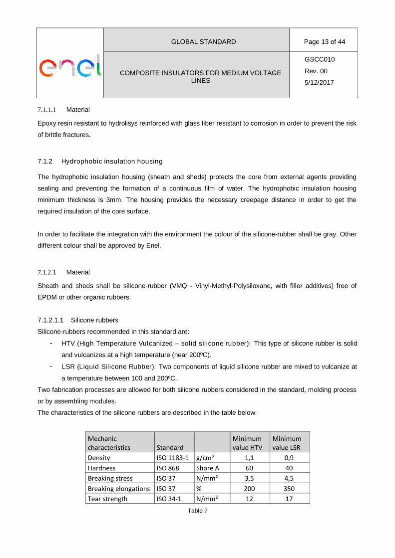
7.1.2.1.1 Silicone rubbers
Silicone-rubbers recommended in this standard are:
- HTV (High Temperature Vulcanized – solid silicone rubber): This type of silicone rubber is solid
and vulcanizes at a high temperature (near 200ºC).
- LSR (Liquid Silicone Rubber): Two components of liquid silicone rubber are mixed to vulcanize at
a temperature between 100 and 200ºC.
Two fabrication processes are allowed for both silicone rubbers considered in the standard, molding process
or by assembling modules.
The characteristics of the silicone rubbers are described in the table below:
Mechaniccharacteristics Standard
Minimumvalue HTV
Minimumvalue LSR
Density ISO 1183-1 g/cm³ 1,1 0,9
Hardness ISO 868 Shore A 60 40
Breaking stress ISO 37 N/mm² 3,5 4,5
Breaking elongations ISO 37 % 200 350
Tear strength ISO 34-1 N/mm² 12 17
Table 7
GLOBAL STANDARD Page 14 of 44
COMPOSITE INSULATORS FOR MEDIUM VOLTAGELINES
GSCC010
Rev. 00
5/12/2017
At every existing interface from the composite insulator, the adhesion strength of the interface (interface
resistance) shall be higher than the tear strength of the silicone.
Silicone-rubbers of insulators shall have a resistance to tracking and electric erosion with a classification of
Class 1A 4,5 according to IEC 60587 and shall resist the effects of corona discharges and ozone. It shall
withstand a low-current arc discharge for more than 300 seconds under the conditions indicated in standard
IEC 61621 and its volume resistivity shall be over 1010·m according to IEC 62631.
The silicone-rubber must be type V0 according to the IEC 60695-11-10.
Additionally the silicone rubber shall have highly hydrophobic features and shall be classified type WC1 as
specified in IEC TS 62073.
7.1.3 Fittings
The fittings transmit the mechanical stress from the ends of the core to the support and to the conductor.
There is a triple junction point located where the core meets the metal coupling and the silicone-rubber
coating ends (connection zone). Usually, the electrical field strength is concentrated in this point, so the
fabrication process shall be careful in this point. The connection zone must be water and air sealed to ensure
the total enclosure of the insulator.
The end fittings shall be directly attached to the core by radial or circumferential compression process for a
better load distribution.
7.1.3.1 Material
Hot dip galvanized forged steel:
High pollution:
- Minimum for individual sample: 500g/m², equivalent to 70m
- Minimum for the average of the whole sample: 600 g/m², equivalent to 85m
Very high pollution:
- Minimum for individual sample: 720g/m², equivalent to 100m
- Minimum for the average of the whole sample: 865 g/m², equivalent to 120m
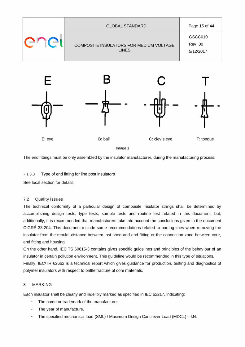
7.1.3.2 Type of end fitting for string insulators
Standard IEC 61466 presents different types of end fittings. The ones selected for this standard are:
GLOBAL STANDARD Page 15 of 44
COMPOSITE INSULATORS FOR MEDIUM VOLTAGELINES
GSCC010
Rev. 00
5/12/2017
E: eye B: ball C: clevis eye T: tongue
Image 1
The end fittings must be only assembled by the insulator manufacturer, during the manufacturing process.
7.1.3.3 Type of end fitting for line post insulators
See local section for details.
7.2 Quality issues
The technical conformity of a particular design of composite insulator strings shall be determined by
accomplishing design tests, type tests, sample tests and routine test related in this document, but,
additionally, it is recommended that manufacturers take into account the conclusions given in the document
CIGRÉ 33-204. This document include some recommendations related to parting lines when removing the
insulator from the mould, distance between last shed and end fitting or the connection zone between core,
end fitting and housing.
On the other hand, IEC TS 60815-3 contains gives specific guidelines and principles of the behaviour of an
insulator in certain pollution environment. This guideline would be recommended in this type of situations.
Finally, IEC/TR 62662 is a technical report which gives guidance for production, testing and diagnostics of
polymer insulators with respect to brittle fracture of core materials.
8 MARKING
Each insulator shall be clearly and indelibly marked as specified in IEC 62217, indicating:
- The name or trademark of the manufacturer.
- The year of manufacture.
- The specified mechanical load (SML) / Maximum Design Cantilever Load (MDCL) – kN.
GLOBAL STANDARD Page 16 of 44
COMPOSITE INSULATORS FOR MEDIUM VOLTAGELINES
GSCC010
Rev. 00
5/12/2017
- Manufacturer reference for the insulator.
- Material maximum voltage
9 TESTING
The composite insulators must be according the standards IEC 62217 (for all types of polymeric insulators),
IEC 61109 (only for string composite insulators) and IEC 61952 (only for line post composite insulators).
Tests are divided into four groups:
- Design tests
- Type tests
- Sample tests
- Routine tests
Design and Type tests are performed once, during the TCA process. Sample and Routine tests shall be
carried out on every singular purchased lot, as an acceptance tests.
9.1.1 Design Tests
These tests are intended to verify the suitability of the designs, materials and methods of manufacture
(technology).
When happens any change in the design, these test must be repeated. IEC 62217 gives the general
recommendation for the criteria and IEC 61109 and 61952 the concrete rules.
The design of a composite insulator is defined by:
- Core and housing materials and their manufacturing method.
- When needed, end fitting material, design and method of attachment (excluding the other fittings of
the string).
- Thickness of the core housing.
- Core diameter.
GLOBAL STANDARD Page 17 of 44
COMPOSITE INSULATORS FOR MEDIUM VOLTAGELINES
GSCC010
Rev. 00
5/12/2017
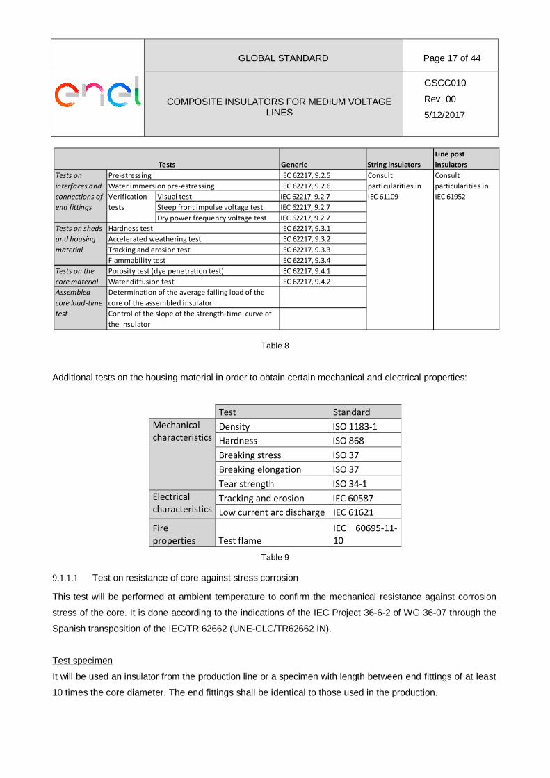
Table 8
Additional tests on the housing material in order to obtain certain mechanical and electrical properties:
Test Standard
Mechanicalcharacteristics
Density ISO 1183-1
Hardness ISO 868
Breaking stress ISO 37
Breaking elongation ISO 37
Tear strength ISO 34-1
Electricalcharacteristics
Tracking and erosion IEC 60587
Low current arc discharge IEC 61621
Fireproperties Test flame
IEC 60695-11-10
Table 9
9.1.1.1 Test on resistance of core against stress corrosion
This test will be performed at ambient temperature to confirm the mechanical resistance against corrosion
stress of the core. It is done according to the indications of the IEC Project 36-6-2 of WG 36-07 through the
Spanish transposition of the IEC/TR 62662 (UNE-CLC/TR62662 IN).
Test specimen
It will be used an insulator from the production line or a specimen with length between end fittings of at least
10 times the core diameter. The end fittings shall be identical to those used in the production.
Generic String insulators
Line post
insulators
IEC 62217, 9.2.5
IEC 62217, 9.2.6
Visual test IEC 62217, 9.2.7
Steep front impulse voltage test IEC 62217, 9.2.7
Dry power frequency voltage test IEC 62217, 9.2.7
IEC 62217, 9.3.1
IEC 62217, 9.3.2
IEC 62217, 9.3.3
IEC 62217, 9.3.4
IEC 62217, 9.4.1
IEC 62217, 9.4.2
Tests
Consult
particularities in
IEC 61109
Consult
particularities in
IEC 61952
Pre-stressing
Tests on the
core material
Porosity test (dye penetration test)
Water diffusion test
Assembled
core load-time
test
Determination of the average failing load of the
core of the assembled insulator
Control of the slope of the strength-time curve of
the insulator
Water immersion pre-estressing
Verification
tests
Tests on
interfaces and
connections of
end fittings
Tests on sheds
and housing
material
Hardness test
Accelerated weathering test
Tracking and erosion test
Flammability test
GLOBAL STANDARD Page 18 of 44
COMPOSITE INSULATORS FOR MEDIUM VOLTAGELINES
GSCC010
Rev. 00
5/12/2017
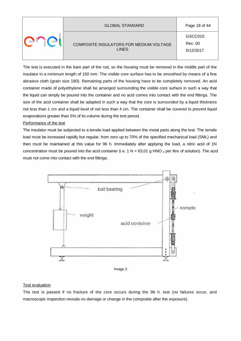
The test is executed in the bare part of the rod, so the housing must be removed in the middle part of the
insulator in a minimum length of 150 mm. The visible core surface has to be smoothed by means of a fine
abrasive cloth (grain size 180). Remaining parts of the housing have to be completely removed. An acid
container made of polyethylene shall be arranged surrounding the visible core surface in such a way that
the liquid can simply be poured into the container and no acid comes into contact with the end fittings. The
size of the acid container shall be adapted in such a way that the core is surrounded by a liquid thickness
not less than 1 cm and a liquid level of not less than 4 cm. The container shall be covered to prevent liquid
evaporations greater than 5% of its volume during the test period.
Performance of the test
The insulator must be subjected to a tensile load applied between the metal parts along the test. The tensile
load must be increased rapidly but regular, from zero up to 70% of the specified mechanical load (SML) and
then must be maintained at this value for 96 h. Immediately after applying the load, a nitric acid of 1N
concentration must be poured into the acid container (i.e. 1 N = 63,01 g HNO 3 per litre of solution). The acid
must not come into contact with the end fittings.
Image 2
Test evaluation
The test is passed if no fracture of the core occurs during the 96 h. test (no failures occur, and
macroscopic inspection reveals no damage or change in the composite after the exposure).
GLOBAL STANDARD Page 19 of 44
COMPOSITE INSULATORS FOR MEDIUM VOLTAGELINES
GSCC010
Rev. 00
5/12/2017
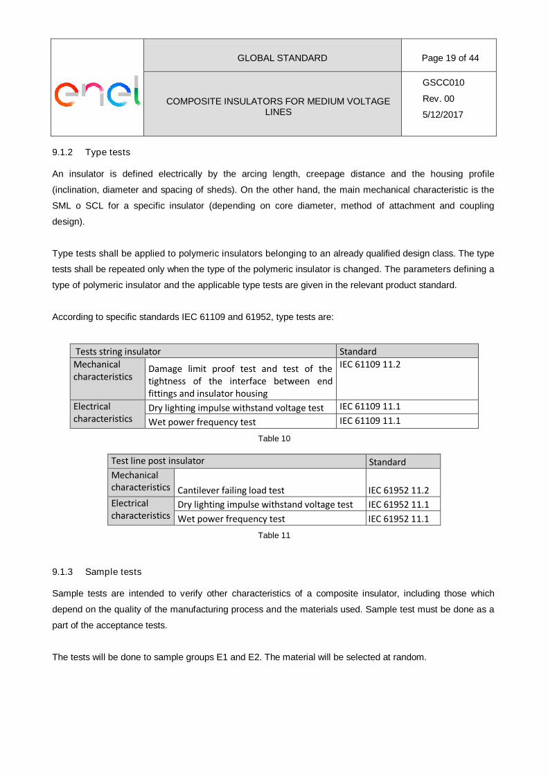
9.1.2 Type tests
An insulator is defined electrically by the arcing length, creepage distance and the housing profile
(inclination, diameter and spacing of sheds). On the other hand, the main mechanical characteristic is the
SML o SCL for a specific insulator (depending on core diameter, method of attachment and coupling
design).
Type tests shall be applied to polymeric insulators belonging to an already qualified design class. The type
tests shall be repeated only when the type of the polymeric insulator is changed. The parameters defining a
type of polymeric insulator and the applicable type tests are given in the relevant product standard.
According to specific standards IEC 61109 and 61952, type tests are:
Tests string insulator Standard
Mechanicalcharacteristics
Damage limit proof test and test of thetightness of the interface between endfittings and insulator housing
IEC 61109 11.2
Electricalcharacteristics
Dry lighting impulse withstand voltage test IEC 61109 11.1
Wet power frequency test IEC 61109 11.1
Table 10
Test line post insulator Standard
Mechanicalcharacteristics Cantilever failing load test IEC 61952 11.2
Electricalcharacteristics
Dry lighting impulse withstand voltage test IEC 61952 11.1
Wet power frequency test IEC 61952 11.1
Table 11
9.1.3 Sample tests
Sample tests are intended to verify other characteristics of a composite insulator, including those which
depend on the quality of the manufacturing process and the materials used. Sample test must be done as a
part of the acceptance tests.
The tests will be done to sample groups E1 and E2. The material will be selected at random.
GLOBAL STANDARD Page 20 of 44
COMPOSITE INSULATORS FOR MEDIUM VOLTAGELINES
GSCC010
Rev. 00
5/12/2017
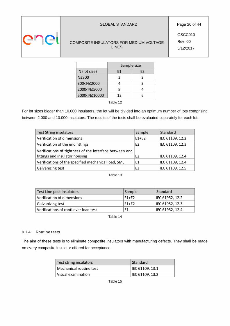
Sample size
N (lot size) E1 E2
N≤300 3 2
300<N≤2000 4 3
2000<N≤5000 8 4
5000<N≤10000 12 6
Table 12
For lot sizes bigger than 10.000 insulators, the lot will be divided into an optimum number of lots comprising
between 2.000 and 10.000 insulators. The results of the tests shall be evaluated separately for each lot.
Test String insulators Sample Standard
Verification of dimensions E1+E2 IEC 61109, 12.2
Verification of the end fittings E2 IEC 61109, 12.3
Verifications of tightness of the interface between endfittings and insulator housing E2 IEC 61109, 12.4
Verifications of the specified mechanical load, SML E1 IEC 61109, 12.4
Galvanizing test E2 IEC 61109, 12.5
Table 13
Test Line post insulators Sample Standard
Verification of dimensions E1+E2 IEC 61952, 12.2
Galvanizing test E1+E2 IEC 61952, 12.3
Verifications of cantilever load test E1 IEC 61952, 12.4
Table 14
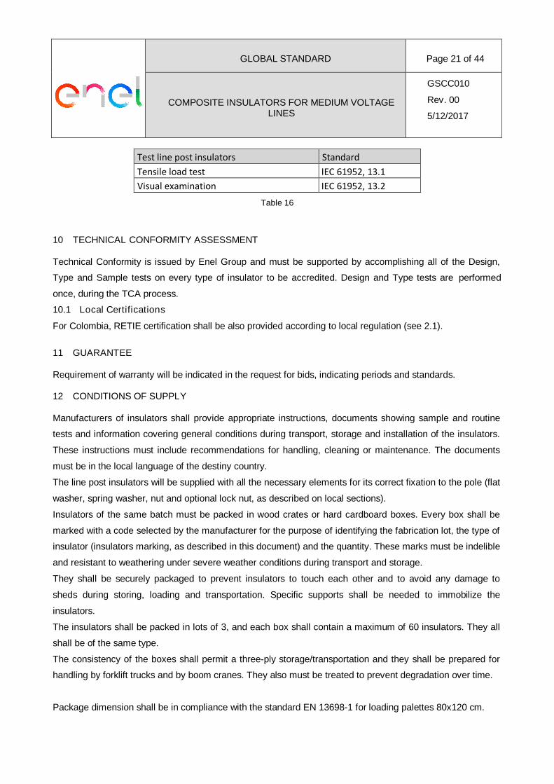
9.1.4 Routine tests
The aim of these tests is to eliminate composite insulators with manufacturing defects. They shall be made
on every composite insulator offered for acceptance.
Test string insulators Standard
Mechanical routine test IEC 61109, 13.1
Visual examination IEC 61109, 13.2
Table 15
GLOBAL STANDARD Page 21 of 44
COMPOSITE INSULATORS FOR MEDIUM VOLTAGELINES
GSCC010
Rev. 00
5/12/2017
Test line post insulators Standard
Tensile load test IEC 61952, 13.1
Visual examination IEC 61952, 13.2
Table 16
10 TECHNICAL CONFORMITY ASSESSMENT
Technical Conformity is issued by Enel Group and must be supported by accomplishing all of the Design,
Type and Sample tests on every type of insulator to be accredited. Design and Type tests are performed
once, during the TCA process.
10.1 Local Certifications
For Colombia, RETIE certification shall be also provided according to local regulation (see 2.1).
11 GUARANTEE
Requirement of warranty will be indicated in the request for bids, indicating periods and standards.
12 CONDITIONS OF SUPPLY
Manufacturers of insulators shall provide appropriate instructions, documents showing sample and routine
tests and information covering general conditions during transport, storage and installation of the insulators.
These instructions must include recommendations for handling, cleaning or maintenance. The documents
must be in the local language of the destiny country.
The line post insulators will be supplied with all the necessary elements for its correct fixation to the pole (flat
washer, spring washer, nut and optional lock nut, as described on local sections).
Insulators of the same batch must be packed in wood crates or hard cardboard boxes. Every box shall be
marked with a code selected by the manufacturer for the purpose of identifying the fabrication lot, the type of
insulator (insulators marking, as described in this document) and the quantity. These marks must be indelible
and resistant to weathering under severe weather conditions during transport and storage.
They shall be securely packaged to prevent insulators to touch each other and to avoid any damage to
sheds during storing, loading and transportation. Specific supports shall be needed to immobilize the
insulators.
The insulators shall be packed in lots of 3, and each box shall contain a maximum of 60 insulators. They all
shall be of the same type.
The consistency of the boxes shall permit a three-ply storage/transportation and they shall be prepared for
handling by forklift trucks and by boom cranes. They also must be treated to prevent degradation over time.
Package dimension shall be in compliance with the standard EN 13698-1 for loading palettes 80x120 cm.
GLOBAL STANDARD Page 22 of 44
COMPOSITE INSULATORS FOR MEDIUM VOLTAGELINES
GSCC010
Rev. 00
5/12/2017
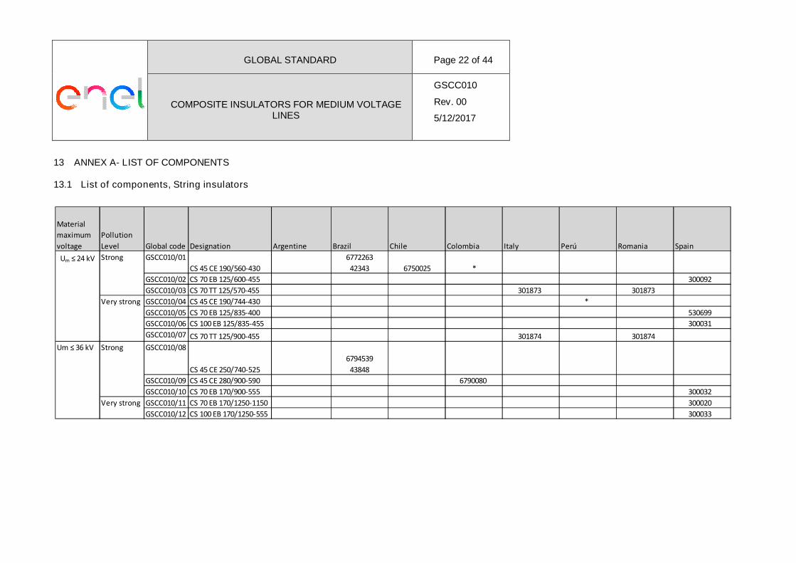
13 ANNEX A- LIST OF COMPONENTS
13.1 List of components, String insulators
Material
maximum
voltage
Pollution
Level Global code Designation Argentine Brazil Chile Colombia Italy Perú Romania Spain
GSCC010/01
CS 45 CE 190/560-430
6772263
42343 6750025 *
GSCC010/02 CS 70 EB 125/600-455 300092
GSCC010/03 CS 70 TT 125/570-455 301873 301873
GSCC010/04 CS 45 CE 190/744-430 *
GSCC010/05 CS 70 EB 125/835-400 530699
GSCC010/06 CS 100 EB 125/835-455 300031
GSCC010/07 CS 70 TT 125/900-455 301874 301874
GSCC010/08
CS 45 CE 250/740-525
6794539
43848
GSCC010/09 CS 45 CE 280/900-590 6790080
GSCC010/10 CS 70 EB 170/900-555 300032
GSCC010/11 CS 70 EB 170/1250-1150 300020
GSCC010/12 CS 100 EB 170/1250-555 300033
Very strong
Um ≤ 36 kV
Very strong
Strong
Um ≤ 24 kV Strong
GLOBAL STANDARD Page 23 of 44
COMPOSITE INSULATORS FOR MEDIUM VOLTAGELINES
GSCC010
Rev. 00
5/12/2017
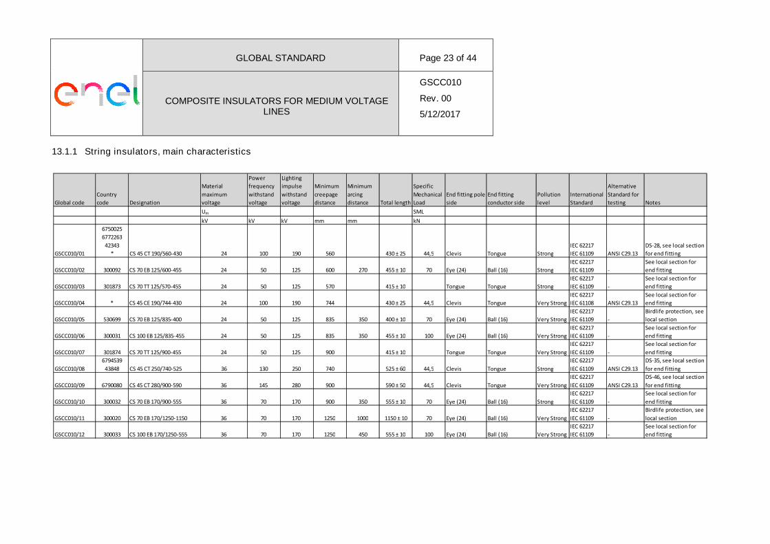
13.1.1 String insulators, main characteristics
Global code
Country
code Designation
Material
maximum
voltage
Power
frequency
withstand
voltage
Lighting
impulse
withstand
voltage
Minimum
creepage
distance
Minimum
arcing
distance Total length
Specific
Mechanical
Load
End fitting pole
side
End fitting
conductor side
Pollution
level
International
Standard
Alternative
Standard for
testing Notes
Um SML
kV kV kV mm mm kN
GSCC010/01
6750025
6772263
42343
* CS 45 CT 190/560-430 24 100 190 560 430 ± 25 44,5 Clevis Tongue Strong
IEC 62217
IEC 61109 ANSI C29.13
DS-28, see local section
for end fitting
GSCC010/02 300092 CS 70 EB 125/600-455 24 50 125 600 270 455 ± 10 70 Eye (24) Ball (16) Strong
IEC 62217
IEC 61109 -
See local section for
end fitting
GSCC010/03 301873 CS 70 TT 125/570-455 24 50 125 570 415 ± 10 Tongue Tongue Strong
IEC 62217
IEC 61109 -
See local section for
end fitting
GSCC010/04 * CS 45 CE 190/744-430 24 100 190 744 430 ± 25 44,5 Clevis Tongue Very Strong
IEC 62217
IEC 61108 ANSI C29.13
See local section for
end fitting
GSCC010/05 530699 CS 70 EB 125/835-400 24 50 125 835 350 400 ± 10 70 Eye (24) Ball (16) Very Strong
IEC 62217
IEC 61109 -
Birdlife protection, see
local section
GSCC010/06 300031 CS 100 EB 125/835-455 24 50 125 835 350 455 ± 10 100 Eye (24) Ball (16) Very Strong
IEC 62217
IEC 61109 -
See local section for
end fitting
GSCC010/07 301874 CS 70 TT 125/900-455 24 50 125 900 415 ± 10 Tongue Tongue Very Strong
IEC 62217
IEC 61109 -
See local section for
end fitting
GSCC010/08
6794539
43848 CS 45 CT 250/740-525 36 130 250 740 525 ± 60 44,5 Clevis Tongue Strong
IEC 62217
IEC 61109 ANSI C29.13
DS-35, see local section
for end fitting
GSCC010/09 6790080 CS 45 CT 280/900-590 36 145 280 900 590 ± 50 44,5 Clevis Tongue Very Strong
IEC 62217
IEC 61109 ANSI C29.13
DS-46, see local section
for end fitting
GSCC010/10 300032 CS 70 EB 170/900-555 36 70 170 900 350 555 ± 10 70 Eye (24) Ball (16) Strong
IEC 62217
IEC 61109 -
See local section for
end fitting
GSCC010/11 300020 CS 70 EB 170/1250-1150 36 70 170 1250 1000 1150 ± 10 70 Eye (24) Ball (16) Very Strong
IEC 62217
IEC 61109 -
Birdlife protection, see
local section
GSCC010/12 300033 CS 100 EB 170/1250-555 36 70 170 1250 450 555 ± 10 100 Eye (24) Ball (16) Very Strong
IEC 62217
IEC 61109 -
See local section for
end fitting
GLOBAL STANDARD Page 24 of 44
COMPOSITE INSULATORS FOR MEDIUM VOLTAGELINES
GSCC010
Rev. 00
5/12/2017
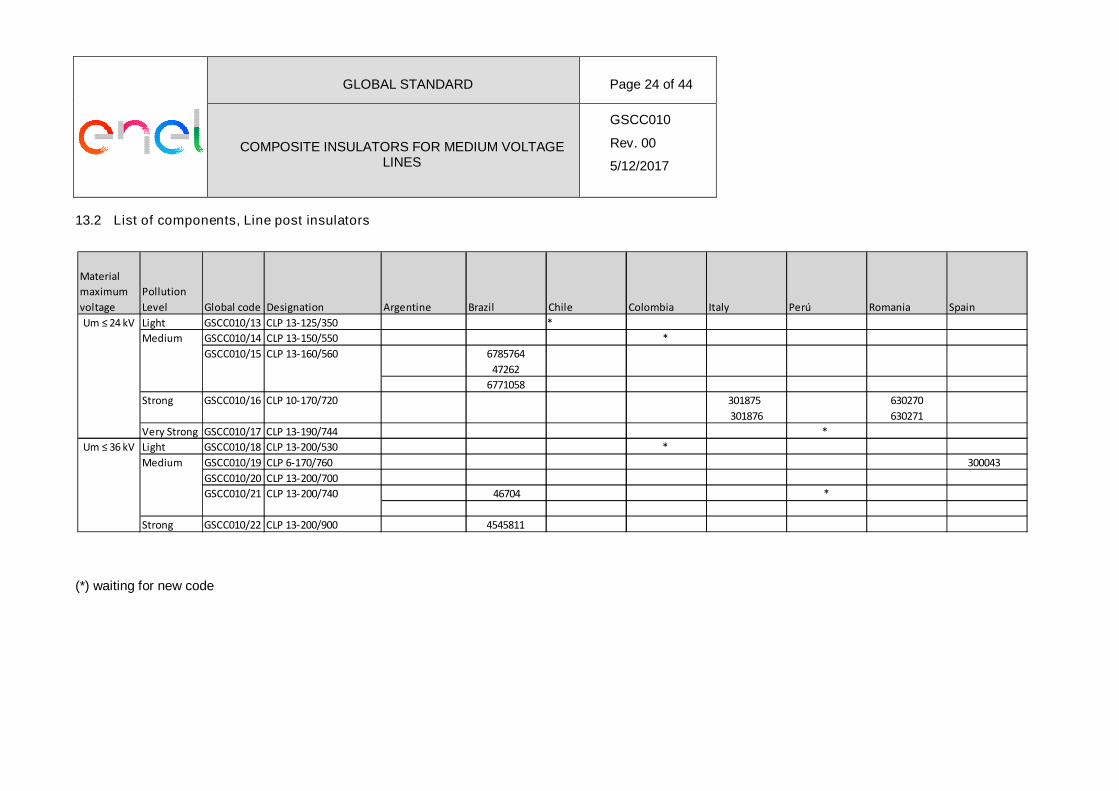
13.2 List of components, Line post insulators
(*) waiting for new code
Material
maximum
voltage
Pollution
Level Global code Designation Argentine Brazil Chile Colombia Italy Perú Romania Spain
Light GSCC010/13 CLP 13-125/350 *
GSCC010/14 CLP 13-150/550 *
6785764
47262
6771058
Strong GSCC010/16 CLP 10-170/720 301875
301876
630270
630271
Very Strong GSCC010/17 CLP 13-190/744 *
Light GSCC010/18 CLP 13-200/530 *
GSCC010/19 CLP 6-170/760 300043
GSCC010/20 CLP 13-200/700
46704 *
Strong GSCC010/22 CLP 13-200/900 4545811
GSCC010/15 CLP 13-160/560
GSCC010/21 CLP 13-200/740
Medium
Um ≤ 24 kV
Medium
Um ≤ 36 kV
GLOBAL STANDARD Page 25 of 44
COMPOSITE INSULATORS FOR MEDIUM VOLTAGELINES
GSCC010
Rev. 00
5/12/2017
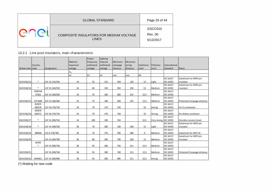
13.2.1 Line post insulators, main characteristics
(*) Waiting for new code
Global code
Country
code Designation
Material
maximum
voltage
Power
frequency
withstand
voltage
Lighting
impulse
withstand
voltage
Minimum
creepage
distance
Minimum
arcing
distance
Cantilever
Load
Pollution
level
International
Standard Notes
Um
kV kV kV mm mm kN
GSCC010/13 * CLP 13-125/350 24 55 125 350 165 13 Light
IEC 62217
IEC 61952
Substitute for HDPE pin
insulator
GSCC010/14 * CLP 13-150/550 24 60 150 550 230 13 Medium
IEC 62217
IEC 61952
Substitute for HDPE pin
insulator
6785764
47262 CLP 13-160/560 24 70 160 560 241 12,5 Medium
IEC 62217
IEC 61952
6771058 CLP 13-160/560 24 70 160 560 241 12,5 Medium
IEC 62217
IEC 61952 Protected Creepage distance
301875
630270 CLP 10-170/720 24 70 170 720 10 Strong
IEC 62217
IEC 61952 For Cu conductor
301876
630271 CLP 10-170/720 24 70 170 720 10 Strong
IEC 62217
IEC 61952 For Aldrey conductor
GSCC010/17 * CLP 13-190/744 24 100 190 744 12,5 Very strong
IEC 62217
IEC 61952 Consider ceramic head
GSCC010/18 * CLP 13-200/530 36 70 200 530 260 13 Light
IEC 62217
IEC 61952
Substitute for HDPE pin
insulator
GSCC010/19 300043 CLP 6-170/760 36 70 170 760 280 6 Medium
IEC 62217
IEC 61952 Substitute for ARVI 42
GSCC010/20 CLP 13-200/700 36 80 200 700 260 13 Medium
IEC 62217
IEC 61952
Substitute for HDPE pin
insulator
46704
* CLP 13-200/740 36 95 200 740 311 12,5 Medium
IEC 62217
IEC 61952
CLP 13-200/740 36 95 200 740 311 12,5 Medium
IEC 62217
IEC 61952 Protected Creepage distance
GSCC010/22 4545811 CLP 13-200/900 36 95 200 900 311 12,5 Strong
IEC 62217
IEC 61952
GSCC010/16
GSCC010/15
GSCC010/21
GLOBAL STANDARD Page 26 of 44
COMPOSITE INSULATORS FOR MEDIUM VOLTAGELINES
GSCC010
Rev. 00
5/12/2017
14 ANNEX B- LOCAL SECTIONS
14.1 E-DISTRIBUZIONE-ITALIA, E-DISTRIBUȚIE BANAT, E-DISTRIBUȚIE DOBROGEA, E-
DISTRIBUȚIE MUNTENIA
14.1.1 Replaced Local standards:
- String insulators: DJ 511 and DJ 511 RO
- Line post insulators: DJ 502 and DJ502/2 RO
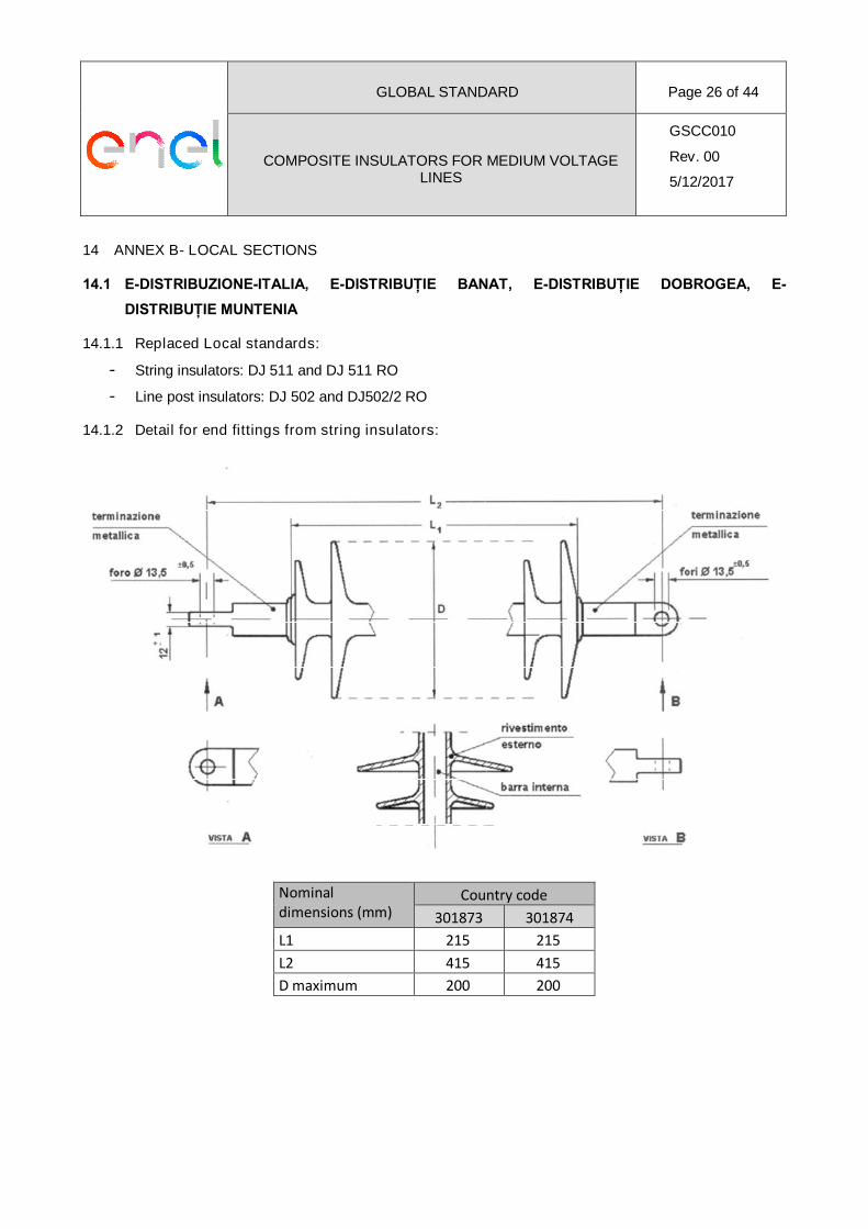
14.1.2 Detail for end fittings from string insulators:
Nominaldimensions (mm)
Country code
301873 301874
L1 215 215
L2 415 415
D maximum 200 200
GLOBAL STANDARD Page 27 of 44
COMPOSITE INSULATORS FOR MEDIUM VOLTAGELINES
GSCC010
Rev. 00
5/12/2017
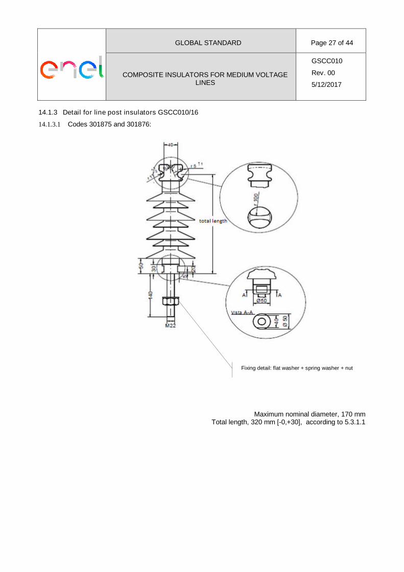
14.1.3 Detail for line post insulators GSCC010/16
14.1.3.1 Codes 301875 and 301876:
Maximum nominal diameter, 170 mmTotal length, 320 mm [-0,+30], according to 5.3.1.1
Fixing detail: flat washer + spring washer + nut
GLOBAL STANDARD Page 28 of 44
COMPOSITE INSULATORS FOR MEDIUM VOLTAGELINES
GSCC010
Rev. 00
5/12/2017
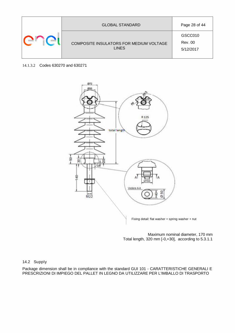
14.1.3.2 Codes 630270 and 630271
Maximum nominal diameter, 170 mmTotal length, 320 mm [-0,+30], according to 5.3.1.1
14.2 Supply
Package dimension shall be in compliance with the standard GUI 101 - CARATTERISTICHE GENERALI EPRESCRIZIONI DI IMPIEGO DEL PALLET IN LEGNO DA UTILIZZARE PER L’IMBALLO DI TRASPORTO
Fixing detail: flat washer + spring washer + nut
GLOBAL STANDARD Page 29 of 44
COMPOSITE INSULATORS FOR MEDIUM VOLTAGELINES
GSCC010
Rev. 00
5/12/2017
14.3 ENDESA DISTRIBUCIÓN ELÉCTRICA- SPAIN
14.3.1 Related Local standards:
- String insulators: AND012
- Line post insulator: 6704113/300043
14.3.2 Marking
It must be included de level of pollution:
- A, Strong pollution level
- MA, Very Strong pollution level
14.3.3 Detail for end fittings from string insulators:
End fittings type ball shall be according to IEC 60120.
14.3.4 Additional comment for GSCC010/05 (country code 530699)
This code is designed to be used in suspensions on vault-type support structures located in areas of birdprotection when the distance between the top of the pole and the central conductor makes it necessary.
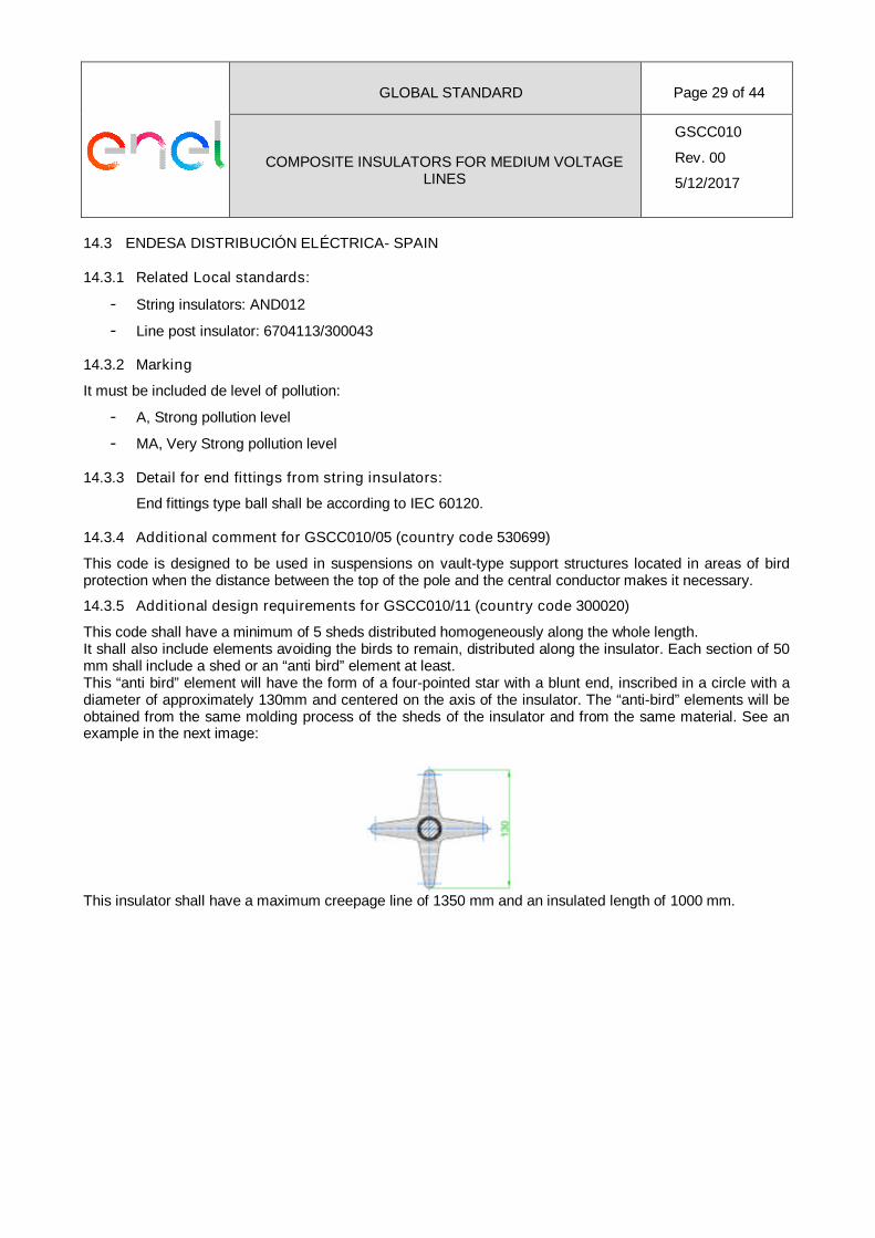
14.3.5 Additional design requirements for GSCC010/11 (country code 300020)
This code shall have a minimum of 5 sheds distributed homogeneously along the whole length.It shall also include elements avoiding the birds to remain, distributed along the insulator. Each section of 50mm shall include a shed or an “anti bird” element at least.This “anti bird” element will have the form of a four-pointed star with a blunt end, inscribed in a circle with adiameter of approximately 130mm and centered on the axis of the insulator. The “anti-bird” elements will beobtained from the same molding process of the sheds of the insulator and from the same material. See anexample in the next image:
This insulator shall have a maximum creepage line of 1350 mm and an insulated length of 1000 mm.
GLOBAL STANDARD Page 30 of 44
COMPOSITE INSULATORS FOR MEDIUM VOLTAGELINES
GSCC010
Rev. 00
5/12/2017
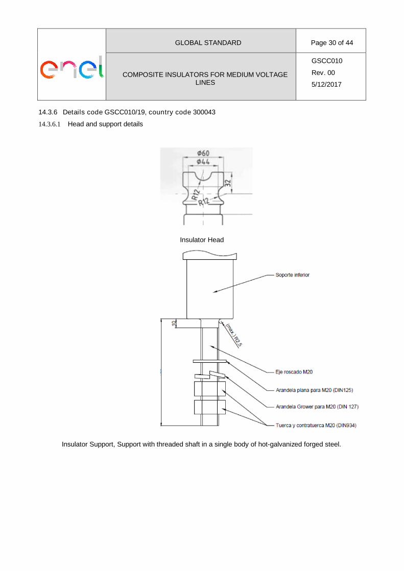
14.3.6 Details code GSCC010/19, country code 300043
14.3.6.1 Head and support details
Insulator Head
Insulator Support, Support with threaded shaft in a single body of hot-galvanized forged steel.
GLOBAL STANDARD Page 31 of 44
COMPOSITE INSULATORS FOR MEDIUM VOLTAGELINES
GSCC010
Rev. 00
5/12/2017
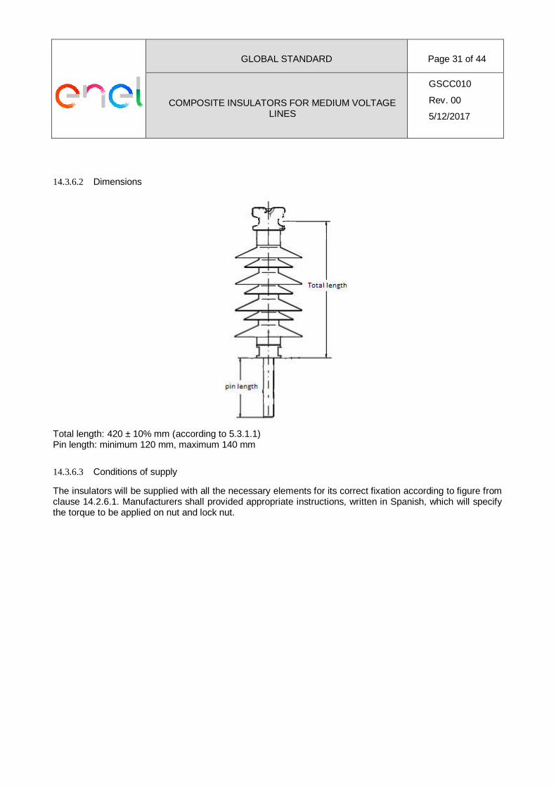
14.3.6.2 Dimensions
Total length: 420 ± 10% mm (according to 5.3.1.1)Pin length: minimum 120 mm, maximum 140 mm
14.3.6.3 Conditions of supply
The insulators will be supplied with all the necessary elements for its correct fixation according to figure fromclause 14.2.6.1. Manufacturers shall provided appropriate instructions, written in Spanish, which will specifythe torque to be applied on nut and lock nut.
GLOBAL STANDARD Page 32 of 44
COMPOSITE INSULATORS FOR MEDIUM VOLTAGELINES
GSCC010
Rev. 00
5/12/2017
14.4 ENEL DISTRIBUCION COLOMBIA, ENEL DISTRIBUCION PERÚ, ENEL DISTRIBUCION CHILE,
ENEL DISTRIBUCAO RIO, ENEL DISTRIBUCAO CEARÁ, ENEL DISTRIBUCAO GOIAS.
14.4.1 Related Local standards:
- E-MT-011
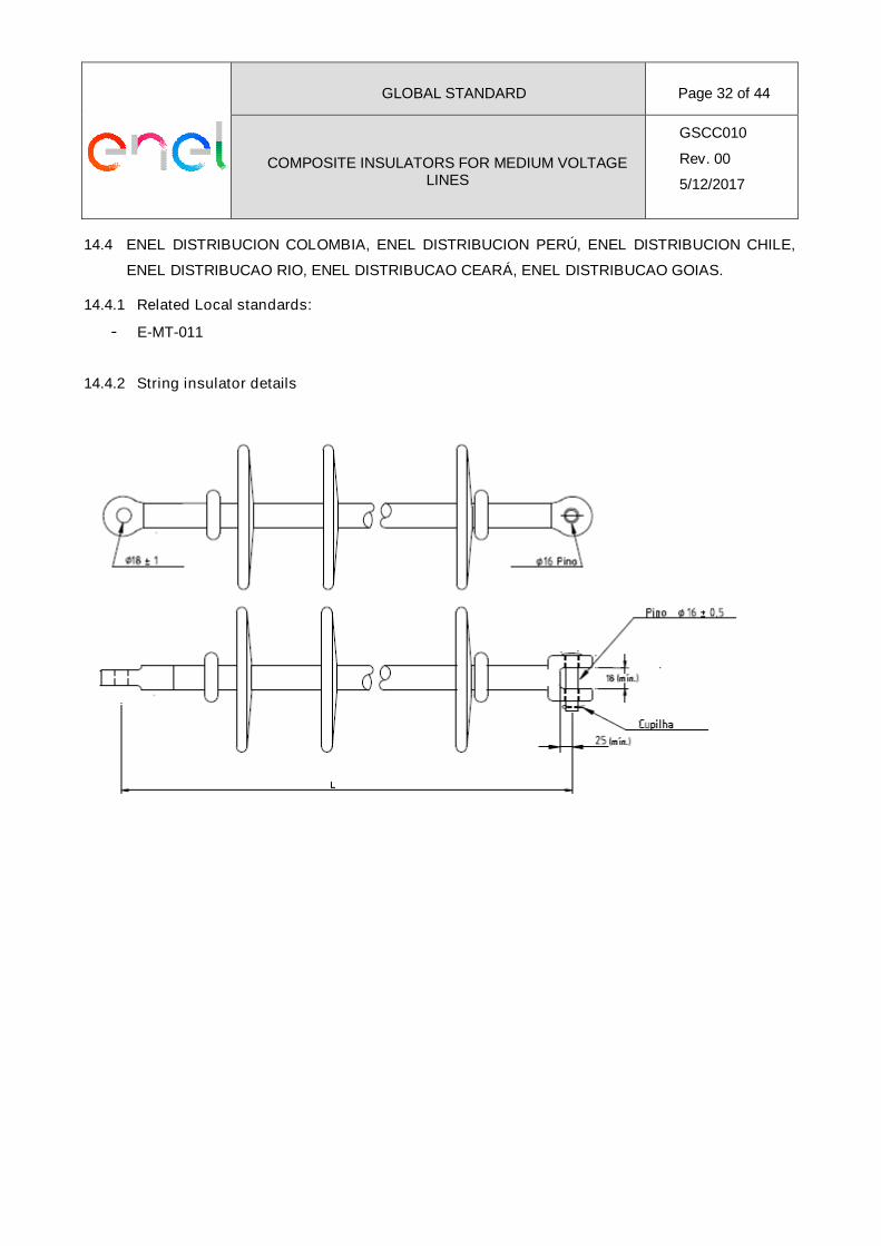
14.4.2 String insulator details
GLOBAL STANDARD Page 33 of 44
COMPOSITE INSULATORS FOR MEDIUM VOLTAGELINES
GSCC010
Rev. 00
5/12/2017
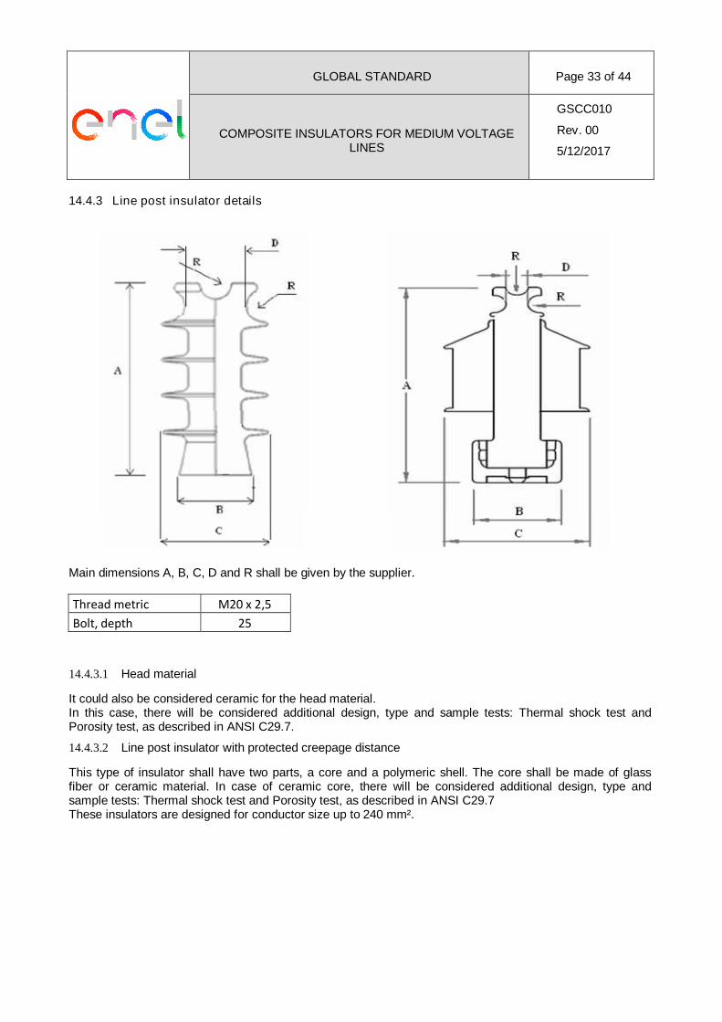
14.4.3 Line post insulator details
Main dimensions A, B, C, D and R shall be given by the supplier.
Thread metric M20 x 2,5
Bolt, depth 25
14.4.3.1 Head material
It could also be considered ceramic for the head material.In this case, there will be considered additional design, type and sample tests: Thermal shock test andPorosity test, as described in ANSI C29.7.
14.4.3.2 Line post insulator with protected creepage distance
This type of insulator shall have two parts, a core and a polymeric shell. The core shall be made of glassfiber or ceramic material. In case of ceramic core, there will be considered additional design, type andsample tests: Thermal shock test and Porosity test, as described in ANSI C29.7These insulators are designed for conductor size up to 240 mm².
GLOBAL STANDARD Page 34 of 44
COMPOSITE INSULATORS FOR MEDIUM VOLTAGELINES
GSCC010
Rev. 00
5/12/2017
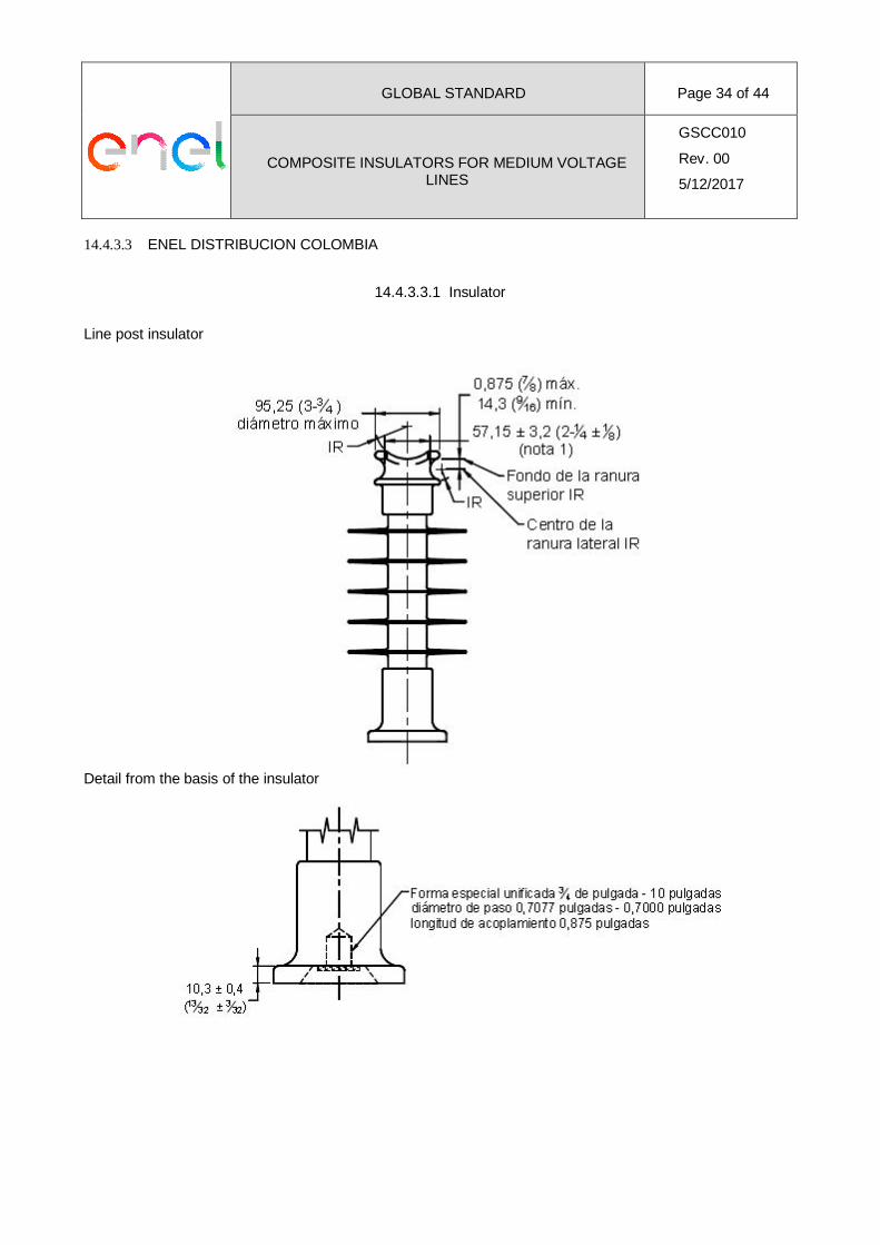
14.4.3.3 ENEL DISTRIBUCION COLOMBIA
14.4.3.3.1 Insulator
Line post insulator
Detail from the basis of the insulator
GLOBAL STANDARD Page 35 of 44
COMPOSITE INSULATORS FOR MEDIUM VOLTAGELINES
GSCC010
Rev. 00
5/12/2017
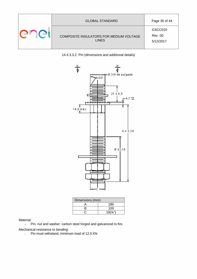
14.4.3.3.2 Pin (dimensions and additional details)
Dimensions (mm)A 180B 100C 19(¾”)
Material:- Pin, nut and washer: carbon steel forged and galvanized to fire.
Mechanical resistance to bending:- Pin must withstand, minimum load of 12.5 KN
GLOBAL STANDARD Page 36 of 44
COMPOSITE INSULATORS FOR MEDIUM VOLTAGELINES
GSCC010
Rev. 00
5/12/2017
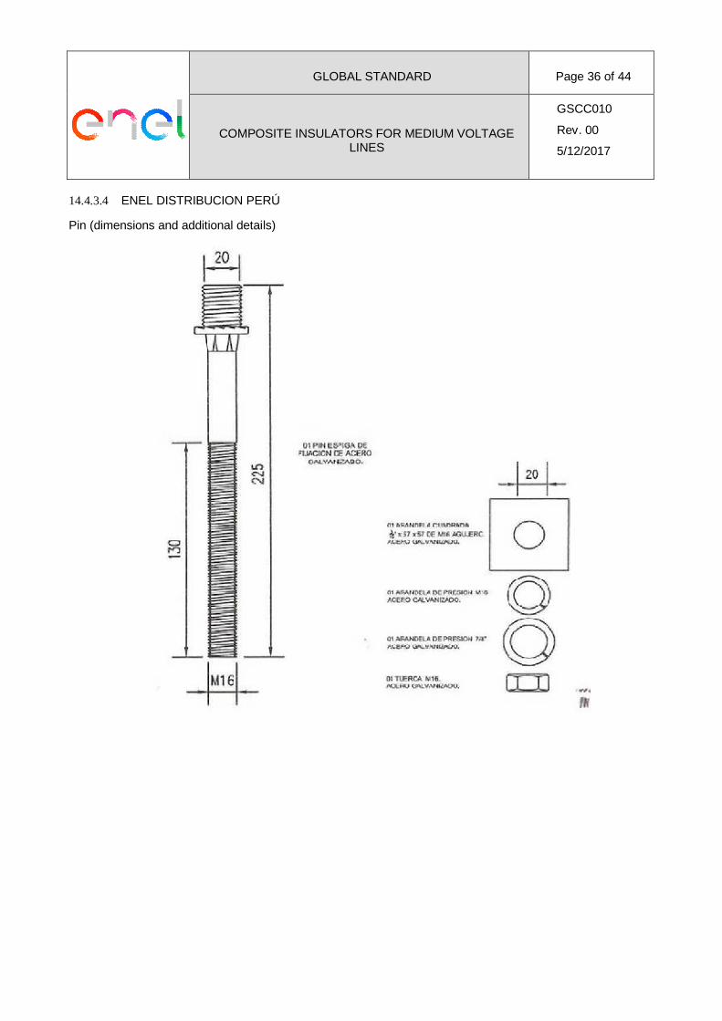
14.4.3.4 ENEL DISTRIBUCION PERÚ
Pin (dimensions and additional details)
GLOBAL STANDARD Page 37 of 44
COMPOSITE INSULATORS FOR MEDIUM VOLTAGELINES
GSCC010
Rev. 00
5/12/2017
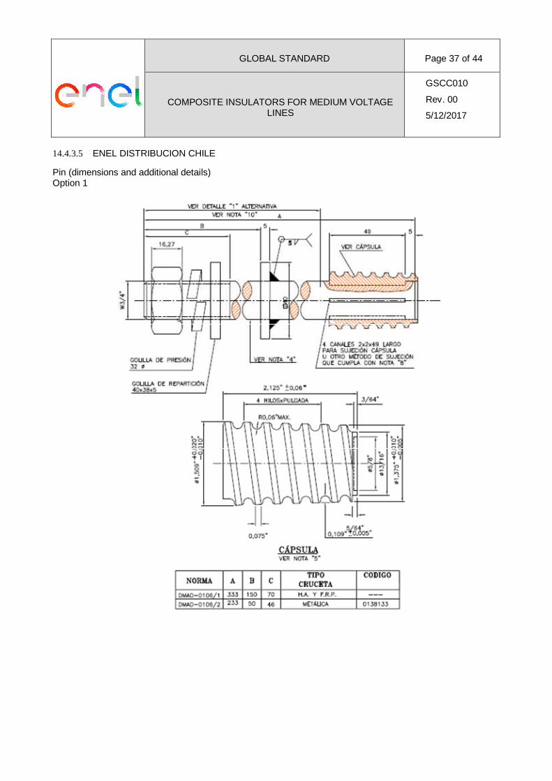
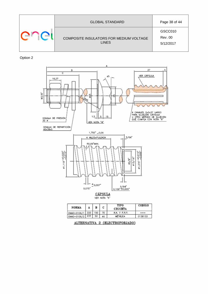
14.4.3.5 ENEL DISTRIBUCION CHILE
Pin (dimensions and additional details)Option 1
GLOBAL STANDARD Page 38 of 44
COMPOSITE INSULATORS FOR MEDIUM VOLTAGELINES
GSCC010
Rev. 00
5/12/2017
Option 2

GLOBAL STANDARD Page 39 of 44
COMPOSITE INSULATORS FOR MEDIUM VOLTAGELINES
GSCC010
Rev. 00
5/12/2017
Additional details
GLOBAL STANDARD Page 40 of 44
COMPOSITE INSULATORS FOR MEDIUM VOLTAGELINES
GSCC010
Rev. 00
5/12/2017
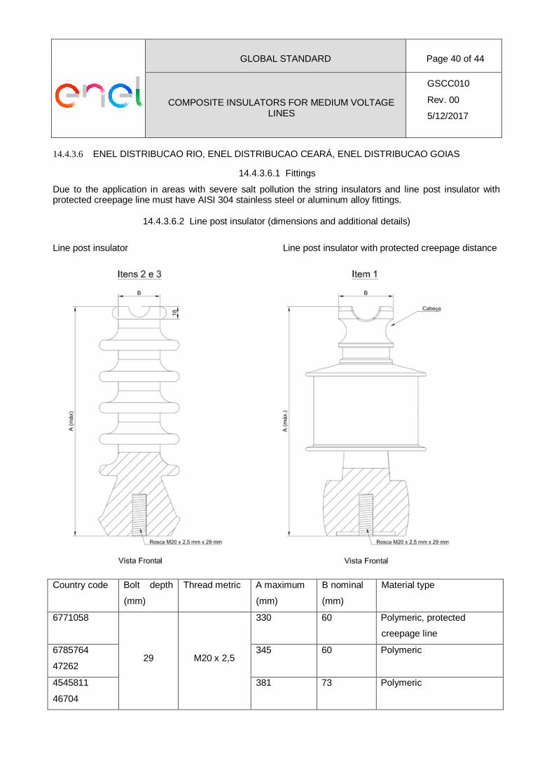
14.4.3.6 ENEL DISTRIBUCAO RIO, ENEL DISTRIBUCAO CEARÁ, ENEL DISTRIBUCAO GOIAS
14.4.3.6.1 Fittings
Due to the application in areas with severe salt pollution the string insulators and line post insulator withprotected creepage line must have AISI 304 stainless steel or aluminum alloy fittings.
14.4.3.6.2 Line post insulator (dimensions and additional details)
Line post insulator Line post insulator with protected creepage distance
Country code Bolt depth
(mm)
Thread metric A maximum
(mm)
B nominal
(mm)
Material type
6771058
29 M20 x 2,5
330 60 Polymeric, protected
creepage line
6785764
47262
345 60 Polymeric
4545811
46704
381 73 Polymeric
GLOBAL STANDARD Page 41 of 44
COMPOSITE INSULATORS FOR MEDIUM VOLTAGELINES
GSCC010
Rev. 00
5/12/2017
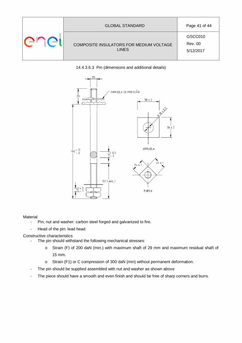
14.4.3.6.3 Pin (dimensions and additional details)
Material- Pin, nut and washer: carbon steel forged and galvanized to fire.
- Head of the pin: lead head.
Constructive characteristics- The pin should withstand the following mechanical stresses:
o Strain (F) of 200 daN (min.) with maximum shaft of 29 mm and maximum residual shaft of
15 mm.
o Strain (F1) or C compression of 300 daN (min) without permanent deformation.
- The pin should be supplied assembled with nut and washer as shown above
- The piece should have a smooth and even finish and should be free of sharp corners and burrs.
GLOBAL STANDARD Page 42 of 44
COMPOSITE INSULATORS FOR MEDIUM VOLTAGELINES
GSCC010
Rev. 00
5/12/2017
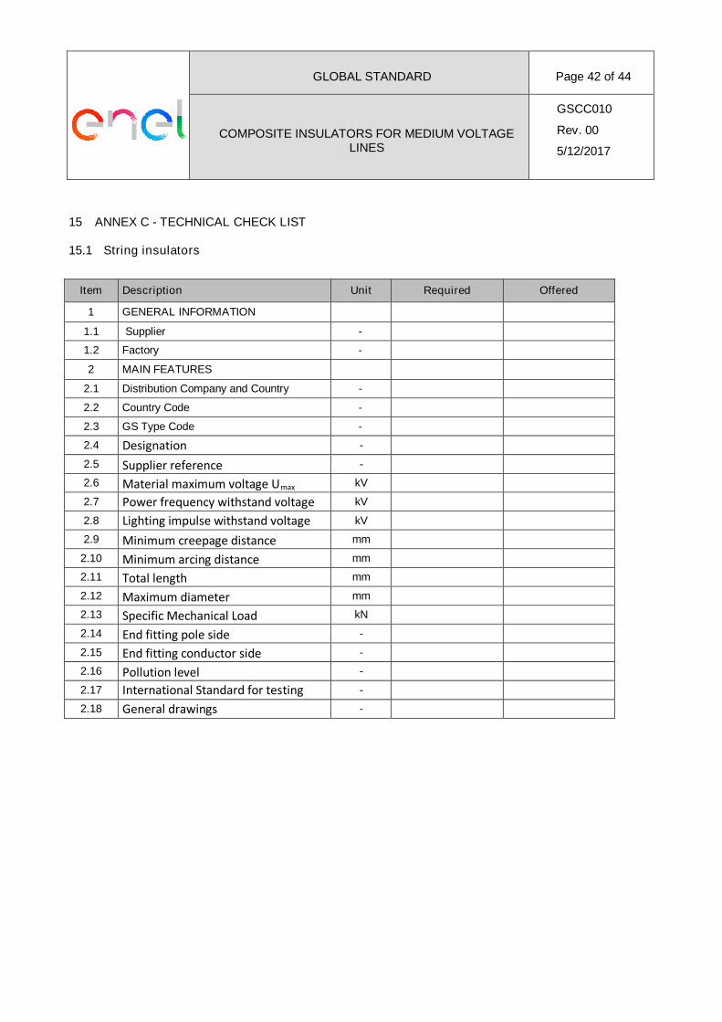
15 ANNEX C - TECHNICAL CHECK LIST
15.1 String insulators
Item Description Unit Required Offered
1 GENERAL INFORMATION
1.1 Supplier -
1.2 Factory -
2 MAIN FEATURES
2.1 Distribution Company and Country -
2.2 Country Code -
2.3 GS Type Code -
2.4 Designation -
2.5 Supplier reference -
2.6 Material maximum voltage Umax kV
2.7 Power frequency withstand voltage kV
2.8 Lighting impulse withstand voltage kV
2.9 Minimum creepage distance mm
2.10 Minimum arcing distance mm
2.11 Total length mm
2.12 Maximum diameter mm
2.13 Specific Mechanical Load kN
2.14 End fitting pole side -
2.15 End fitting conductor side -
2.16 Pollution level -
2.17 International Standard for testing -
2.18 General drawings -
GLOBAL STANDARD Page 43 of 44
COMPOSITE INSULATORS FOR MEDIUM VOLTAGELINES
GSCC010
Rev. 00
5/12/2017
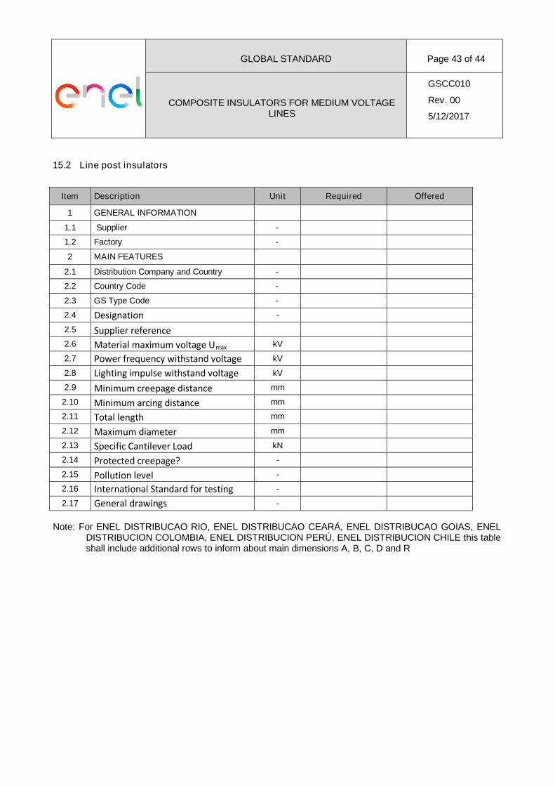
15.2 Line post insulators
Item Description Unit Required Offered
1 GENERAL INFORMATION
1.1 Supplier -
1.2 Factory -
2 MAIN FEATURES
2.1 Distribution Company and Country -
2.2 Country Code -
2.3 GS Type Code -
2.4 Designation -
2.5 Supplier reference
2.6 Material maximum voltage Umax kV
2.7 Power frequency withstand voltage kV
2.8 Lighting impulse withstand voltage kV
2.9 Minimum creepage distance mm
2.10 Minimum arcing distance mm
2.11 Total length mm
2.12 Maximum diameter mm
2.13 Specific Cantilever Load kN
2.14 Protected creepage? -
2.15 Pollution level -
2.16 International Standard for testing -
2.17 General drawings -
Note: For ENEL DISTRIBUCAO RIO, ENEL DISTRIBUCAO CEARÁ, ENEL DISTRIBUCAO GOIAS, ENELDISTRIBUCION COLOMBIA, ENEL DISTRIBUCION PERÚ, ENEL DISTRIBUCION CHILE this tableshall include additional rows to inform about main dimensions A, B, C, D and R
GLOBAL STANDARD Page 44 of 44
COMPOSITE INSULATORS FOR MEDIUM VOLTAGELINES
GSCC010
Rev. 00
5/12/2017
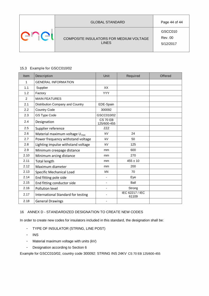
15.3 Example for GSCC010/02
Item Description Unit Required Offered
1 GENERAL INFORMATION
1.1 Supplier XX
1.2 Factory YYY
2 MAIN FEATURES
2.1 Distribution Company and Country EDE-Spain
2.2 Country Code 300092
2.3 GS Type Code GSCC010/02
2.4 DesignationCS 70 EB
125/600-455
2.5 Supplier reference ZZZ
2.6 Material maximum voltage Umax kV 24
2.7 Power frequency withstand voltage kV 50
2.8 Lighting impulse withstand voltage kV 125
2.9 Minimum creepage distance mm 600
2.10 Minimum arcing distance mm 270
2.11 Total length mm 455 ± 10
2.12 Maximum diameter mm 200
2.13 Specific Mechanical Load kN 70
2.14 End fitting pole side - Eye
2.15 End fitting conductor side - Ball
2.16 Pollution level - Strong
2.17 International Standard for testing -IEC 62217 / IEC
61109
2.18 General Drawings -
16 ANNEX D - STANDARDIZED DESIGNATION TO CREATE NEW CODES
In order to create new codes for insulators included in this standard, the designation shall be:
- TYPE OF INSULATOR (STRING, LINE POST)
- INS
- Material maximum voltage with units (kV)
- Designation according to Section 6
Example for GSCC010/02, country code 300092: STRING INS 24KV CS 70 EB 125/600-455