composite power system reliability improvement using tcsc
TRANSCRIPT
International Journal of Scientific & Engineering Research Volume 11, Issue 2, February-2020 1369
ISSN 2229-5518
IJSER © 2020
http://www.ijser.org
Composite Power System Reliability Improvement using TCSC
SURESH KUMAR T, SANKAR V
(Only author names, for other information use the space provided at the bottom (left side) of first page or last page. Don’t superscript numbers for authors )
Abstract— FACTS technologies can have major positive impacts on power system reliability performance and the actual benefits obtained
can be assessed using suitable models and practice. Emerging techniques for composite power system reliability evaluation mainly focus
on conventional generation and transmission facilities. In this paper, improvement of Reliability in composite electric power system is
examined by incorporating Thyristor Controlled Series Capacitor (TCSC). A 6 bus RBTS (Roy Billinton Test system) is considered to show
major improvement in reliability. A state space reliability model of multi-module TCSC has been developed and incorporated in the system.
Load point & System indices performances are presented to examine the impact of TCSC on the composite electric power system
reliability. Investigation results show a significant improvement in the Load point & system indices when utilizing TCSC.
Index Terms—TCSC; RBTS; Load Indices, System Indices, State Space, Composite Power System.
—————————— ——————————
1 INTRODUCTION
Flexible AC transmission system (FACTS) technology is the ultimate tool for getting the most out of existing equipment via faster control action and new capabilities.
The most striking feature is the ability to directly control transmission line flows by structurally changing parameters of the fast switching.
Thyristor Controlled Series Capacitor (TCSC) is an im-portant FACTS component which makes it possible to vary the apparent impedance of a specific transmission line so as to force power flow along a path. This controlled impedance [1] can be programmed to react in a planned way to contingencies so as to greatly enhance power system security. Using this ap-proach [2] it is possible to operate stably at power levels well beyond those for which the system was originally intended. Addition of capacitors in series with the transmission line is called series compensation, it can be fixed, and i.e. capacitance in the line remains fixed and cannot be altered [3-4]. It is also possible to provide alteration of series capacitance by means of thyristors [5-6]. Such a system becomes Flexible AC Trans-mission System (FACTS) [7-8].
In this paper, the impact of TCSC on composite electric power system reliability of 6 bus RBTS is examined. TCSCs are employed in a system to adjust the transmission infeed im-pedances and therefore, increase the transmission system ca-pacity without increasing the system fault current levels [9-10]. Load point & system indices performances are presented to examine the impact of TCSC on the 6 bus RBTS test system.
2 THYRISTOR CONTROLLED SERIES CAPACITOR
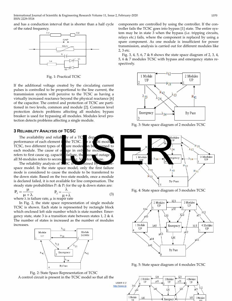
Fig. 1 shows a TCSC module [1] with different protection elements. Basically it comprises a series capacitor C, in parallel with a Thyristor Controlled Reactor (TCR) Ls. A Metal Oxide Varistor (MOV) essentially a nonlinear resistor is connected across the series capacitor to prevent the occurrence of high capacitor over voltage. Not only does the MOV limit in the circuit even during fault conditions, it helps to improve the transient stability. A circuit breaker is also installed across the TCSC module to bypass it if a severe fault or equipment mal-function [1] occurs. A current limiting inductor, Ld is incorpo-rated in the circuit to restrict both the magnitude and the fre-quency of the capacitor current during the capacitor bypass operation.
It consists of series compensating capacitor shunted by a thyristor controlled reactor. In a practical TCSC implementa-tion, several such basic compensators may be connected in series to obtain the desired voltage rating and operating char-acteristics. Basic idea behind the TCSC scheme is to provide a continuously variable capacitor by means of partially cancel-ing the effective compensating capacitance by the TCR.
TCR at fundamental system frequency [7] is continuously variable reactive impedance, controllable by delay angle α. The steady state impedance of the TCSC is that of a parallel LC circuit, consisting of a fixed capacitive impedance, XC, and a variable inductive impedance XL(α), i.e., (1) (2)
XL = ωL and α is delay angle measured from the crest of the
capacitor voltage. In each module, the capacitor bank is provided with a par-
allel thyristor controlled inductor that circulates current pulses which add in phase with the line current. This boosts the ca-pacitor voltage beyond the level that would be obtained by the line current alone. Each thyristor is triggered once per cycle
F
————————————————
Suresh Kumar is currently pursuing Doctoral degree program in Electrical Engineering inJNTUA, Anantapur,India, & working as an Assoc. Prof. in EEE Dept., at Vishnu Instituet of Technology, Bhimavaram, India, E-mail:[email protected].
Dr. V. Sankar is currently working as a Professor in Electrical Engg. Dept., at College of Engineering, JNTUA, Anantapur, India and he is also Registrar of JNTUA, Anantapur,India, E-mail: [email protected]
)(XX
2sin 2X)(X LLLL
CL
LCTCSC
X)(X
)(XX)(X
IJSER
International Journal of Scientific & Engineering Research Volume 11, Issue 2, February-2020 1370
ISSN 2229-5518
IJSER © 2020
http://www.ijser.org
and has a conduction interval that is shorter than a half cycle of the rated frequency.
Fig. 1: Practical TCSC If the additional voltage created by the circulating current pulses is controlled to be proportional to the line current, the transmission system will perceive to the TCSC as having a virtually increased reactance beyond the physical reactance [6] of the capacitor. The control and protection of TCSC are parti-tioned in two levels, common and module [2]. Common level protection detects problems affecting all modules; bypass breaker is used for bypassing all modules. Modules level pro-tection detects problems affecting a single module.
3 RELIABILITY ANALYSIS OF TCSC
The availability and reliability of a TCSC depends on the performance of each element in the TCSC. For a multi module TCSC, two different types of failure modes can be assigned to each module. The cause of outage in only the module itself refers to first cause eg. capacitor failure, the cause of outage of all M-modules refers to second cause eg. Varistor failure.
The reliability analysis of TCSC is determined by the state-space model. In the state space model, only the first failure mode is considered to cause the module to be transferred to the down state. Based on the two state models, once a module is declared failed, it is not available for line compensation. The steady state probabilities P1 & P2 for the up & down states are:
(3) where is failure rate, is reapir rate
In Fig. 2, the state space representation of single module TCSC is shown. Each state is represented by rectangle block which enclosed left side number which is state number. Emer-gency state, state 3 is a transition state between states 1, 2 & 4. The number of states is increased as the number of modules increases.
Fig. 2: State Space Representation of TCSC A control circuit is present in the TCSC model so that all the
components are controlled by using the controller. If the con-troller fails the TCSC goes into bypass [1] state. The entire sys-tem may be in state 3 when the bypass (i.e. tripping circuits, relays etc.) fails, where the component is replaced by using a spare component. As one module is insufficient for power transmission, analysis is carried out for different modules like 2, 3 etc. Fig. 3, 4, 5, 6, 7 & 8 shows the state space diagram of 2, 3, 4, 5, 6 & 7 modules TCSC with bypass and emergency states re-spectively.
Fig. 3: State space diagram of 2 modules TCSC
Fig. 4: State space diagram of 3 modules TCSC
Fig. 5: State space diagram of 4 modules TCSC
1P
2P
IJSER
International Journal of Scientific & Engineering Research Volume 11, Issue 2, February-2020 1371
ISSN 2229-5518
IJSER © 2020
http://www.ijser.org
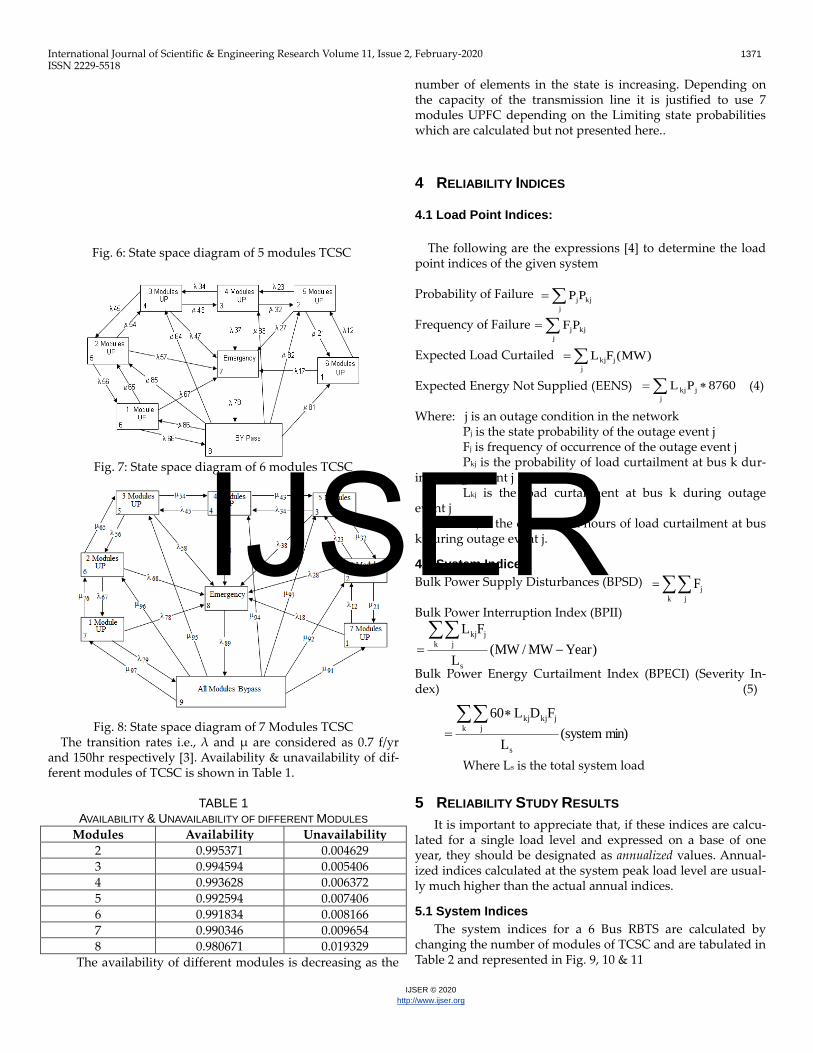
Fig. 6: State space diagram of 5 modules TCSC
Fig. 7: State space diagram of 6 modules TCSC
Fig. 8: State space diagram of 7 Modules TCSC The transition rates i.e., λ and μ are considered as 0.7 f/yr and 150hr respectively [3]. Availability & unavailability of dif-ferent modules of TCSC is shown in Table 1.
TABLE 1
AVAILABILITY & UNAVAILABILITY OF DIFFERENT MODULES Modules Availability Unavailability
2 0.995371 0.004629 3 0.994594 0.005406 4 0.993628 0.006372 5 0.992594 0.007406 6 0.991834 0.008166 7 0.990346 0.009654 8 0.980671 0.019329
The availability of different modules is decreasing as the
number of elements in the state is increasing. Depending on the capacity of the transmission line it is justified to use 7 modules UPFC depending on the Limiting state probabilities which are calculated but not presented here..
4 RELIABILITY INDICES
4.1 Load Point Indices:
The following are the expressions [4] to determine the load point indices of the given system Probability of Failure Frequency of Failure Expected Load Curtailed Expected Energy Not Supplied (EENS) (4) Where: j is an outage condition in the network Pj is the state probability of the outage event j Fj is frequency of occurrence of the outage event j Pkj is the probability of load curtailment at bus k dur-ing outage event j Lkj is the load curtailment at bus k during outage event j Dkj is the duration in hours of load curtailment at bus k during outage event j.
4.2 System Indices:
Bulk Power Supply Disturbances (BPSD) Bulk Power Interruption Index (BPII) Bulk Power Energy Curtailment Index (BPECI) (Severity In-dex) (5) Where Ls is the total system load
5 RELIABILITY STUDY RESULTS
It is important to appreciate that, if these indices are calcu-lated for a single load level and expressed on a base of one year, they should be designated as annualized values. Annual-ized indices calculated at the system peak load level are usual-ly much higher than the actual annual indices.
5.1 System Indices
The system indices for a 6 Bus RBTS are calculated by changing the number of modules of TCSC and are tabulated in Table 2 and represented in Fig. 9, 10 & 11
j
kjjPP
)MW(FLj
jkj
j
kjjPF
j
jkj 8760PL
k j
jF
)YearMW/MW(L
FL
s
k j
jkj
min)system(L
FDL60
s
k j
jkjkj
IJSER
International Journal of Scientific & Engineering Research Volume 11, Issue 2, February-2020 1372
ISSN 2229-5518
IJSER © 2020
http://www.ijser.org
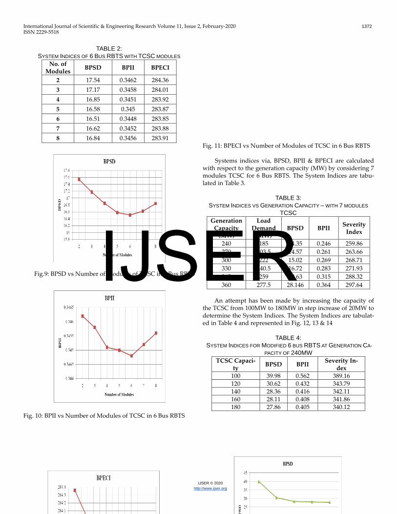
TABLE 2:
SYSTEM INDICES OF 6 BUS RBTS WITH TCSC MODULES No. of
Modules BPSD BPII BPECI
2 17.54 0.3462 284.36
3 17.17 0.3458 284.01
4 16.85 0.3451 283.92
5 16.58 0.345 283.87
6 16.51 0.3448 283.85
7 16.62 0.3452 283.88
8 16.84 0.3456 283.91
Fig.9: BPSD vs Number of Modules of TCSC in 6 Bus RBTS Fig. 10: BPII vs Number of Modules of TCSC in 6 Bus RBTS
Fig. 11: BPECI vs Number of Modules of TCSC in 6 Bus RBTS
Systems indices via, BPSD, BPII & BPECI are calculated
with respect to the generation capacity (MW) by considering 7 modules TCSC for 6 Bus RBTS. The System Indices are tabu-lated in Table 3.
TABLE 3:
SYSTEM INDICES VS GENERATION CAPACITY – WITH 7 MODULES
TCSC
Generation Capacity
(MW)
Load Demand
(MW) BPSD BPII
Severity Index
240 185 14.35 0.246 259.86
270 203.5 14.57 0.261 263.66
300 222 15.02 0.269 268.71
330 240.5 16.72 0.283 271.93
345 259 20.63 0.315 288.32
360 277.5 28.146 0.364 297.64
An attempt has been made by increasing the capacity of
the TCSC from 100MW to 180MW in step increase of 20MW to determine the System Indices. The System Indices are tabulat-ed in Table 4 and represented in Fig. 12, 13 & 14
TABLE 4:
SYSTEM INDICES FOR MODIFIED 6 BUS RBTS AT GENERATION CA-
PACITY OF 240MW
TCSC Capaci-ty
BPSD BPII Severity In-
dex 100 39.98 0.562 389.16 120 30.62 0.432 343.79 140 28.36 0.416 342.11 160 28.11 0.408 341.86 180 27.86 0.405 340.12
IJSER
International Journal of Scientific & Engineering Research Volume 11, Issue 2, February-2020 1373
ISSN 2229-5518
IJSER © 2020
http://www.ijser.org
Fig. 12: BPSD vs TCSC Capacity of 6 Bus Modified RBTS
Fig. 13: BPII vs TCSC Capacity of 6 Bus Modified RBTS
Fig. 14: BPECI vs TCSC Capacity of 6 Bus Modified RBTS
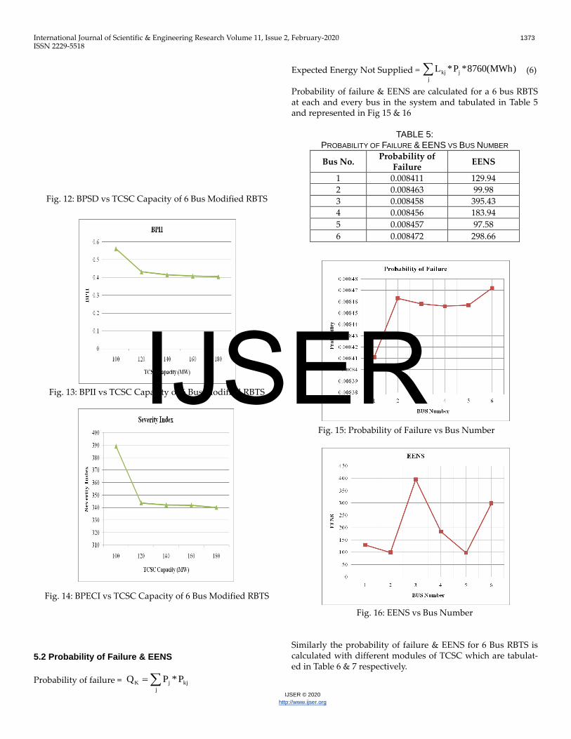
5.2 Probability of Failure & EENS
Probability of failure =
Expected Energy Not Supplied = (6) Probability of failure & EENS are calculated for a 6 bus RBTS at each and every bus in the system and tabulated in Table 5 and represented in Fig 15 & 16
TABLE 5:
PROBABILITY OF FAILURE & EENS VS BUS NUMBER
Bus No. Probability of
Failure EENS
1 0.008411 129.94
2 0.008463 99.98
3 0.008458 395.43
4 0.008456 183.94
5 0.008457 97.58
6 0.008472 298.66
Fig. 15: Probability of Failure vs Bus Number
Fig. 16: EENS vs Bus Number
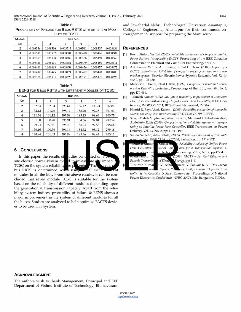
Similarly the probability of failure & EENS for 6 Bus RBTS is calculated with different modules of TCSC which are tabulat-ed in Table 6 & 7 respectively.
j
kjjK P*PQ
j
jkj )MWh(8760*P*L
IJSER
International Journal of Scientific & Engineering Research Volume 11, Issue 2, February-2020 1374
ISSN 2229-5518
IJSER © 2020
http://www.ijser.org
Table 6
PROBABILITY OF FAILURE FOR 6 BUS RBTS WITH DIFFERENT MOD-
ULES OF TCSC
Module
No.
Bus No.
1 2 3 4 5 6
2 0.008536 0.008516 0.008513 0.008511 0.008507 0.008634
3 0.008511 0.008507 0.008501 0.008498 0.008496 0.008602
4 0.008459 0.008498 0.008489 0.008486 0.008489 0.008562
5 0.008416 0.008491 0.008481 0.008479 0.008480 0.008511
6 0.008411 0.008463 0.008458 0.008456 0.008457 0.008472
7 0.008417 0.008475 0.008474 0.008472 0.008470 0.008489
8 0.008426 0.008494 0.008496 0.008494 0.008491 0.008496
Table 7
EENS FOR 6 BUS RBTS WITH DIFFERENT MODULES OF TCSC
Module
No.
Bus No.
1 2 3 4 5 6
2 132.64 102.34 398.64 186.42 100.24 302.84
3 132.12 101.96 398.14 185.96 99.38 301.63
4 131.54 101.12 397.58 185.13 98.66 300.75
5 131.08 100.78 396.91 184.66 97.81 299.54
6 129.94 99.98 395.43 183.94 97.58 298.66
7 130.16 100.36 396.16 184.52 98.12 299.18
8 130.84 101.03 396.88 185.66 99.42 300.11
6 CONCLUSIONS
In this paper, the results of studies conducted on a compo-site electric power system model to investigate the impact of TCSC on the system reliability are presented. The analysis of 6 bus RBTS is determined when using TCSC with different modules in all the bus. From the above results, it can be con-cluded that seven module TCSC is suitable for the system based on the reliability of different modules depending upon the generation & transmission capacity. Apart from the relia-bility, system indices, probability of failure & EENS shows a major improvement in the system of different modules for all the buses. Studies are analyzed to help optimize FACTS devic-es to be used in a system.
ACKNOWLEDGMENT
The authors wish to thank Management, Prinicipal and EEE Department of Vishnu Institute of Technology, Bhimavaram,
and Jawaharlal Nehru Technological Univeristy Anantapur, College of Engineering, Anantapur for their continuous en-courgaement & support for preparing the Manuscript.
REFERENCES
[1] Roy Billinton; Yu Cui, (2002). Reliability Evaluation of Composite Electric
Power Systems Incorporating FACTS, Proceeding of the IEEE Canadian
Conference on Electrical and Computer Engineering, pp: 1-6.
[2] Ajit Kumar Verma; A. Srividya, Bimal C. Deka, (2004). Impact of a
FACTS controller on Reliability of composite power generation and trans-
mission system, Elsevier, Electric Power Systems Research, Vol. 72, Is-
sue 2, pp: 125-130.
[3] Mario V. F. Pereira; Neal J. Balu, (1992). Composite Generation / Trans-
mission Reliability Evaluation, Proceedings of the IEEE, vol. 80, No. 4,
pp: 470-491.
[4] T. Suresh Kumar; V. Sankar, (2011) Reliability Improvement of Composite
Electric Power System using Unified Power Flow Controller, IEEE Con-
ference, INDICON 2011, BITS-Pilani, Hyderabad, INDIA.
[5] Hamid R. Bay; Ahad. Kazemi, (2009). Reliability evaluation of composite
electric power systems incorporating STATCOM & UPFC, IEEE.
[6] Sayed-Mahdi Moghadasi; Ahad Kazemi; Mahmud Fotuhi-Firuzabad;
Abdel-Aty Edris (2008). Composite system reliability assessment incorpo-
rating an Interline Power Flow Controller, IEEE Transactions on Power
Delivery, Vol. 23, No. 2, pp: 1191-1199.
[7] Sreten Skuletic; Adis Balota, (2005). Reliability assessment of composite
power systems, IEEE CCECE/CCGEI, Saskatoon, pp: 1718-1721.
[8] T. Suresh Kumar; V. Sankar (2008). Reliability Analysis of Unified Power
Flow Controllers & Series Compensator for a Transmission System, i-
manager’s journal on Electrical Engineering, Vol. 2, No. 2, pp:47-54.
[9] Klaus Habur; Donal O’Leary (2008). FACTS – For Cost Effective and
Reliable Transmission of Electrical Energy, pp: 1-11.
[10] T. Suresh Kumar; D. V. Ashok Kumar; V. Sankar; K. V. Desikachar
(2007). Transmission System Reliability Analysis using Thyristor Con-
trolled Series Capacitor & Series Compensator, Proceedings of National
Power Electronics Conference (NPEC-2007), IISc, Bangalore, INDIA.
IJSER