composite pressure vessels for · pdf filefluids under pressure. ... composite pressure...
TRANSCRIPT
THE 19TH
INTERNATIONAL CONFERENCE ON COMPOSITE MATERIALS
1 Introduction
A new generation of composite pressure vessels for
large scale market applications has been studied in
this work. The vessels consist on a plastic liner
wrapped with a filament winding glass fibre
reinforced polymer matrix structure. A polyethylene
(PE) was selected as liner for water at room
temperatures applications and a thermosetting resin
was used as matrices in the glass reinforced filament
wound laminate.
For applications having higher service temperatures,
such as, thermal accumulators and solar panel
vessels, thermoplastics presenting greater
temperature performance, for example,
polypropylene (PP), polyamide (PA), polycarbonate
(PC) Polyvinylidene difluoride (PVDF) or even
thermosettings are being studied for application as
vessel liners.
Traditional materials, such as, steel, are successfully
being replaced by polymer matrix composites
materials in the construction of pressure cylinders
for many common applications. The use of polymer
composites allows minimising the weight,
improving the aesthetic and also increasing the
pressure vessel mechanical, impact and corrosion
behaviour [1]. These are important attributes in
many present and future industrial and
non-industrial large scale applications, such as, for
example, liquid filters and accumulators, hydrogen
cell storage vessels, oxygen bottles, etc.
Multi-axial filament winding is the most adequate
processing technology to produce composite vessels
for medium to high internal pressures at serial
industrial level [2, 3]. Such technology allows
processing simultaneously the vessel cylinder and
domes and use non-geodesic optimised fibre patterns
in the composite laminate layers that permit
withstand the higher mechanical efforts involved
with lower vessel-wall thicknesses.
This work is part of a larger study concerning the
development of a new generation of filament wound
composite vessels to be applied on the storage of
fluids under pressure. The present paper only covers
an initial part of the work that concerns the
manufacture and simulation of the behaviour of
pressure vessels made from fibre reinforced
thermosetting matrix composites.
A vessel consisting in a thermoplastic liner wrapped
with a filament winding glass fibre reinforced
thermosetting resin structure has been studied. The
finite element analysis (FEM) was used to predict
the pressure vessel mechanical behaviour according
to the requirements of the EN 13923:2005 standard,
namely, the minimum internal burst pressure.
The paper will present the design of a multi-axial
filament winding prototype equipment that will be
constructed for being used in the manufacture of the
initial prototype vessels.
The paper will also present and discuss results
obtained from internal pressure tests made in
thermoplastic liners and will compare them with
those ones obtained from the FEM simulations made.
2 Manufacturing the composite pressure vessels
2.1 Pressure vessel requirements
According to the market demands, three main
groups of vessels with the following requirements
were selected to be studied in this work:
COMPOSITE PRESSURE VESSELS FOR COMMERCIAL APPLICATIONS
L. Oliveira
1*, J. P. Nunes
2, J. F. Silva
3, B. Barros
1, L. Amorim
4, M. Vasconcelos
4
PIEP - Pole for Innovation in Polymer Engineering, Minho University, 4800-058 Guimaraes, Portugal 2 Institute of Polymers and Composites/I3N, Minho University, 4800-058 Guimaraes, Portugal
3 Dep. of mechanical Engineering ISEP, 4200-072 Porto, Portugal
4 VIDROPOL, SA, Apartado 2001-Castelo da Maia, 4471-908 Avioso (Sta Maria), Portugal
* Corresponding author ([email protected])
Keywords: Filament winding; composite vessels, pressure vessels, thermoplastic liner; FEM
analysis; mechanical properties; internal pressure tests
ICCM19 3145

i) Group I (expansion vessels and swimming pool
filters):
- maximum pressure: 1 MPa
- maximum temperature: 40 ºC
ii) Group II (Electric water heaters and other thermal
accumulators):
- ,maximum pressure: 1 MPa
- maximum temperature: 80 ° C
iii) Group III (expansion tanks using glycol as heat
exchanger fluid):
- maximum pressure: 0.3 MPa
- maximum temperature: 130 ° C
Table 1 summarizes further requirements for the
above mentioned pressure vessels.
2.2 Raw materials
As mentioned before, the pressure vessels will
consist in an internal plastic liner (to be integral part
of the final vessel) wrapped with a filament winding
continuous glass fiber reinforced polymer matrix
structure. Such vessels present as advantages over
the existing ones much better price/performance
ratio, mechanical strength and corrosion resistance.
Vessels from group I, which demand low service
temperatures, require the use of cheap thermoplastic
liners, such as, polyethylene (PE), and structural
filament winding walls based on an orthophthalic
polyester resin reinforced with continuous E type
glass fibers.
The groups of pressure vessels requiring higher
service temperature ranges must use liners made
from much higher thermal performance polymers,
such as, poly (vinylidene fluoride) (PVDF),
polyamide (PA), polycarbonate (PC), polyacetal
(POM) and/or thermosetting resins (isophthalic
polyester / bisphenolic, vinyl ester).
2.3.1 Liners
To minimize costs, it was decided to start the study
from group I vessels liners, requiring lower
demanding service temperatures (room temperature).
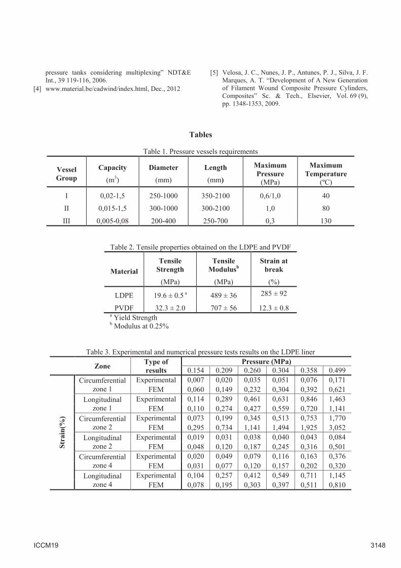
A liner made from cheap low density polyethylene
(LDPE), ICORENE® 1613 from IcoPolymers, was
produced by rotational molding to manufacture these
vessels (Figures 1 and 2).
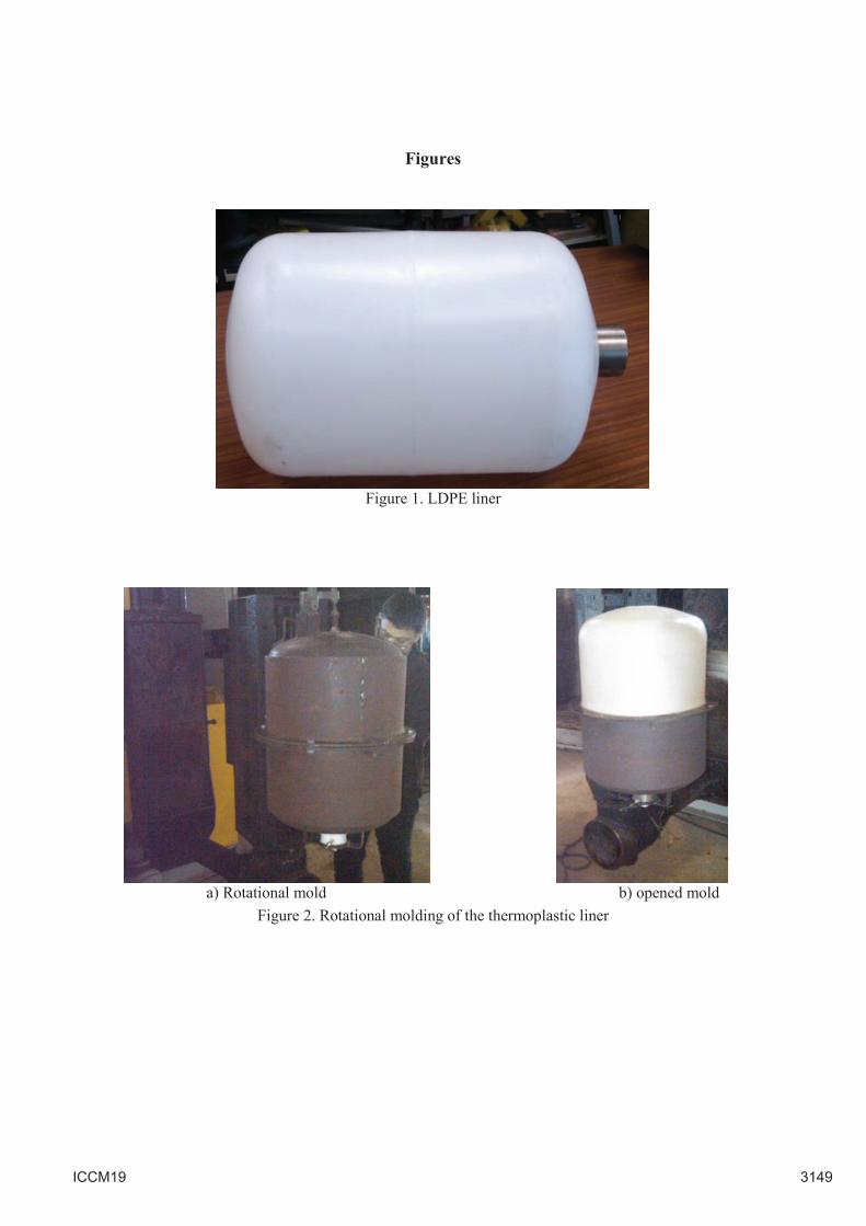
The following geometry/capacity was adopted for
the initial vessels under study(Fig. 3):
- diameter: 400 mm (approx..)
- capacity: 0,07 m3 (approxim.)
- vessels dished end geometry: torispherical
decimal
It were already produced liners for the more
demanding pressure vessels of group III in poly
vinylidene fluoride (PVDF) manufactured by
rotational molding and in glass reinforced
isophthalic thermosetting polyester resin (Fig. 4)
processed by hand-lay-up and vacuum infusion.
For pressure vessels of group II one aims to use a
polypropylene (PP) liner processed by rotational or
blow molding according to the required production
rate.
Fig.5 shows the initial stainless steel fittings
designed to be embedded by polymer in the vessel
dished ends during rotational molding. As leaks
were detected through the larger dished end fitting in
the firsts hydraulic pressure tests made it was
decided to redraw it. Thus, in order to obtain good
sealing this larger fitting was made in two parts able
to be fastening tight into each other with a sealant
(see Fig. 6).
2.3.2 Filament winding structural wall
Glass fiber reinforced thermosetting polyester or
thermoplastic matrices layers were selected to be
used in the structural wall for all types of vessels.
2.3 Processing equipment
Figure 7 shows a schematic drawing of 6-axis
filament winding equipment that was designed to
manufacture initial prototype composite pressure
vessels. The following major geometric
specifications were considered for the equipment:
1500 mm of maximum vessel diameter, 3000 mm of
maximum vessel length, longitudinal, transversal
and vertical head courses of 3020 mm, 610 mm and
1135 mm, respectively, 300º as maximum rotational
angle of head vertical axis and 800 mm as maximum
height of the mandrel rotational axis.
Concerning to the filament winding equipment
speeds the following major specifications were
considered: 0-200 rpm of mandrel rotational speed,
0-1 m/s, 0-0.6 m/s and 0-0.3 m/s as longitudinal,
transversal and vertical head speeds and, 0-110 rpm
as rotational speed of the vertical and horizontal
head axes. Finally, it was considered the possibility
of using 15-20 fiber reinforcing strands
simultaneously and the use of fiber strand bandwidth
of 80 mm.
ICCM19 3146

The CADWIND software from Material Company
[4] was used to simulate the strand fiber path during
the vessel filament winding, using different desired
angles. Figure 8 shows simulations of the fiber
strand trajectory paths for winding angles of 29 º and
89º, respectively.
An assembly comprising a robot Motoman HP-20
and a rotational drive axle was used to assess the
feasibility of the previously defined trajectories
(Figures 9 and 10). Such trajectories have been
validated by the obtained results.
3 Testing
Samples from points 1 to 4 represented in Fig. 3
were cut from the LDPE and PVDF produced liners
were submitted to tensile testing according to ISO
527 standard in a 50 kN Shimadzu universal testing
machine at the crosshead speed of 5 mm/min.
Table 2 summarizes the obtained results. As
expected the PVDF presented higher mechanical
properties (strength an modulus) than the LDPE.
Results also showed that LDPE exhibited a much
more ductile behavior than PVDF.
LDPE liners were submitted to hydraulic pressure
tests at six different pressure levels: 0.154, 0.209,
0.260, 0.304, 0.358 and 0.499 (MPa). Six strain
gauges, three able to measure strains in the
circumferential and the remaining ones in
longitudinal directions, were bonded to the LDPE
liner (Fig. 11) in the zones 1, 2 and 4 shown in
Fig. 3.
Table 3 shows the experimental results obtained and
also numerical ones obtained by FEM analysis. The
ABAQUS® software was used in the FEM
simulations by considering the linear elastic material
approach, the LDPE properties shown in Table 2, a
Poisson’s ratio of 0.37 and the dimensions depicted
in Fig. 3.
As may be seen from results shown in Table 3
substantial differences were obtained between
experimental and FEM results probably due to the
non-application of an elasto-plastic material model
in the numerical simulations as it was demonstrated
by previous studies [5].
4 Conclusions
In this work, concerning the development of glass
fiber reinforced pressure vessels for large scale
market usages, were defined the requirements for
different types of applications. Accordingly to the
defined requirements different raw-materials and
processing technologies were selected to produce the
composite pressure vessels.
A customized filament winding equipment is being
developed by using computer simulations and
robotic experiments and tests.
Liners made of LDPE, PVDF and glass fiber
reinforced unsaturated polyester resin were already
produced by rotational molding and hand-lay-up and
vacuum infusion technologies.
Relevant mechanical properties were already
experimentally determined on liner materials.
Furthermore, LDPE liners were submitted to
hydraulic pressure tests and the obtained
experimental strain results compared with FEM
predictions using a linear elastic material model. The
differences found between experimental and
numerical data suggest the need of using an elasto-
plastic material model in FEM analysis.
Acknowledgments
Authors thank the Portuguese Innovation Agency
(ADI) for financial support given to the QREN
project 21538 – THERMOCOMPRESS.
They also thank the Portuguese Foundation for
Science and Technology (FCT) for the financial
support of IPC through project PEst-
C/CTM/LA0025/2011 (Strategic Project–LA 25,
2011–2012).
Finally, Andreia Vilela, Nuno Gonçalves and
Nuno Vieira deserve a special
acknowledgement due to all personal support
and help given during the tests.
References
[1] Brandt, J., Drechsler, K., Richter, H., “The Use of
High-Performance Thermoplastic Composites for
Structural Aerospace Applications”, 9th Int.
Conference on Composite Materials (ICCM-9), Vol.
6, Madrid, Spain, pp. 143-150, 1993.
[2] Won-Man, C., Bang-Eop, L., Song-Hoe, K., Young-
Shin, L. “Effects of Geometric and Material
Nonlinearity on The Stresses of Various Pressure
Vessel Dome Shapes” Computers & Structures Vol.
55, 6, pp. 1063-1075, 1995.
[3] Kang, D.H., Kim, C.U., Kim, C.G. “The embedment
of fiber Bragg grating sensors into filament wound
ICCM19 3147
pressure tanks considering multiplexing” NDT&E
Int., 39 119-116, 2006.
[4] www.material.be/cadwind/index.html, Dec., 2012
[5] Velosa, J. C., Nunes, J. P., Antunes, P. J., Silva, J. F.
Marques, A. T. “Development of A New Generation
of Filament Wound Composite Pressure Cylinders,
Composites” Sc. & Tech., Elsevier, Vol. 69 (9),
pp. 1348-1353, 2009.
Tables
Table 1. Pressure vessels requirements
Vessel
Group
Capacity
(m3)
Diameter
(mm)
Length
(mm)
Maximum
Pressure
(MPa)
Maximum
Temperature
(ºC)
I 0,02-1,5 250-1000 350-2100 0,6/1,0 40
II 0,015-1,5 300-1000 300-2100 1,0 80
III 0,005-0,08 200-400 250-700 0,3 130
Table 2. Tensile properties obtained on the LDPE and PVDF
Material
Tensile
Strength
(MPa)
Tensile
Modulusb
(MPa)
Strain at
break
(%)
LDPE 19.6 ± 0.5 a 489 ± 36 285 ± 92
PVDF 32.3 ± 2.0 707 ± 56 12.3 ± 0.8
a Yield Strength
b Modulus at 0.25%
Table 3. Experimental and numerical pressure tests results on the LDPE liner
Zone Type of
results
Pressure (MPa)
0.154 0.209 0.260 0.304 0.358 0.499
Str
ain
(%)
Circumferential
zone 1
Experimental 0,007 0,020 0,035 0,051 0,076 0,171
FEM 0,060 0,149 0,232 0,304 0,392 0,621
Longitudinal
zone 1
Experimental 0,114 0,289 0,461 0,631 0,846 1,463
FEM 0,110 0,274 0,427 0,559 0,720 1,141
Circumferential
zone 2
Experimental 0,073 0,199 0,345 0,513 0,753 1,770
FEM 0,295 0,734 1,141 1,494 1,925 3,052
Longitudinal
zone 2
Experimental 0,019 0,031 0,038 0,040 0,043 0,084
FEM 0,048 0,120 0,187 0,245 0,316 0,501
Circumferential
zone 4
Experimental 0,020 0,049 0,079 0,116 0,163 0,376
FEM 0,031 0,077 0,120 0,157 0,202 0,320
Longitudinal
zone 4
Experimental 0,104 0,257 0,412 0,549 0,711 1,145
FEM 0,078 0,195 0,303 0,397 0,511 0,810
ICCM19 3148
Figures
Figure 1. LDPE liner
a) Rotational mold b) opened mold
Figure 2. Rotational molding of the thermoplastic liner
ICCM19 3149
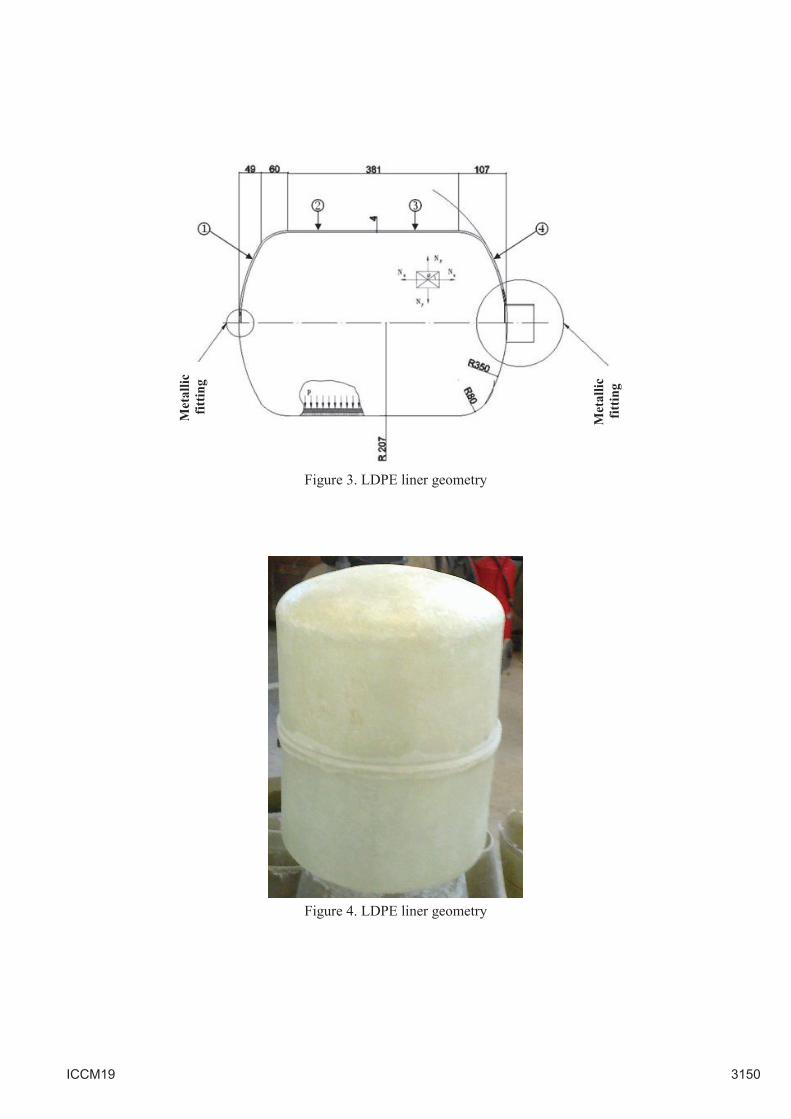
Figure 3. LDPE liner geometry
Figure 4. LDPE liner geometry
Met
all
ic
fi
ttin
g
Met
all
ic
fi
ttin
g
ICCM19 3150
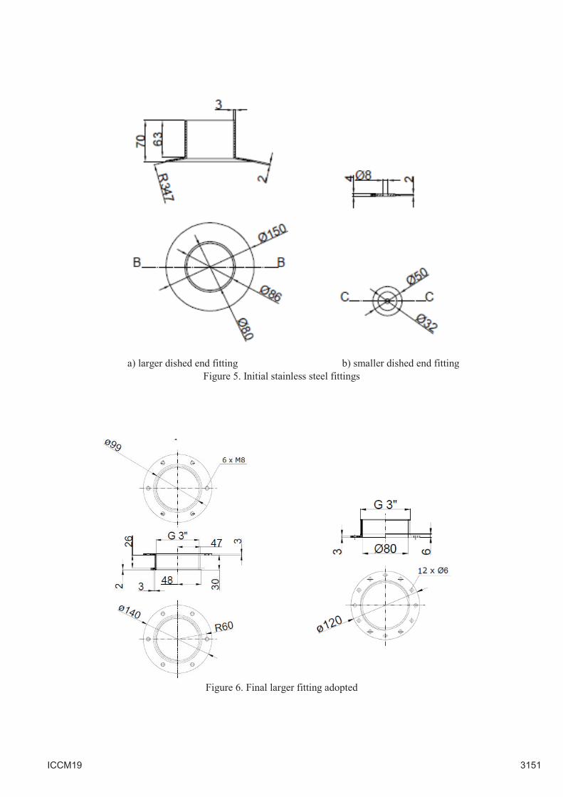
a) larger dished end fitting b) smaller dished end fitting
Figure 5. Initial stainless steel fittings
Figure 6. Final larger fitting adopted
ICCM19 3151
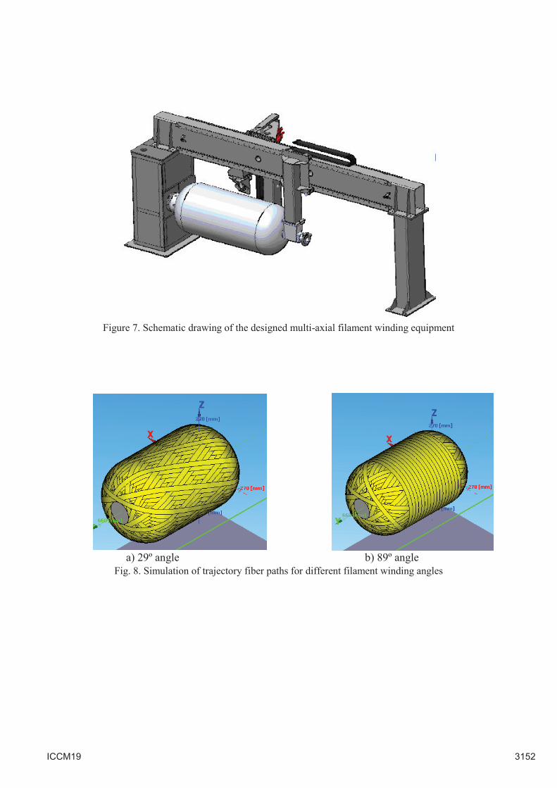
Figure 7. Schematic drawing of the designed multi-axial filament winding equipment
a) 29º angle b) 89º angle
Fig. 8. Simulation of trajectory fiber paths for different filament winding angles
ICCM19 3152
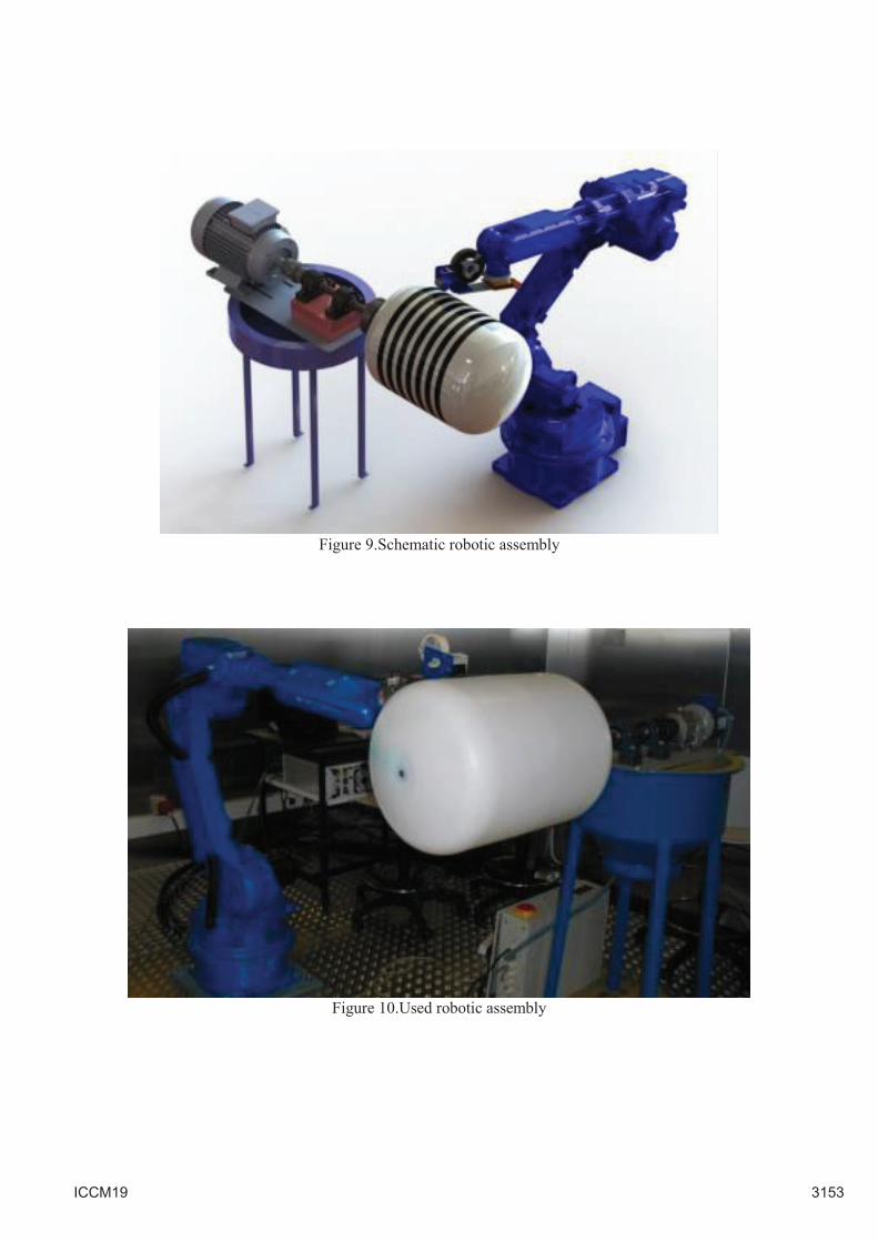
Figure 9.Schematic robotic assembly
Figure 10.Used robotic assembly
ICCM19 3153
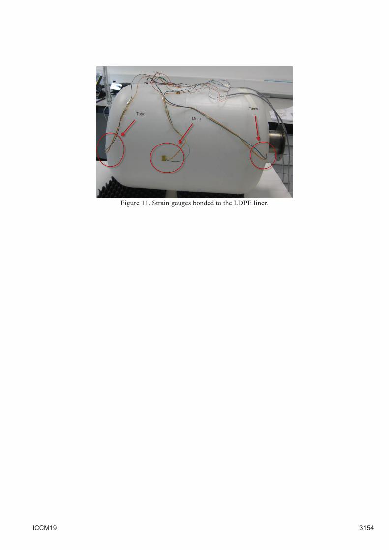
Figure 11. Strain gauges bonded to the LDPE liner.
ICCM19 3154