composite technology for exploration (cte)
TRANSCRIPT

COMPOSITE TECHNOLOGY for EXPLORATION (CTE)
2019 JDMTP Composites Processing and Fabrication Portfolio ReviewAugust 6, 2019
Mallory [email protected]
Development of Composite Bonded Joints for Space Launch Vehicle Structures
1
Outline
• Introduction
• Materials
• Analysis and Design
• Manufacturing
• Testing
• Concluding Remarks
2

Introduction
Motivation For Bonded Composite Joints• NASA is researching development of composite bonded
joints for future Space Launch System (SLS)-scale structures• Current joint designs can account for significant increases in
cost and weight. • Improvements are needed in analytical capabilities required
to predict failure loads/modes in composite structures.
Composite Technology for Exploration (CTE)• Developing and demonstrating critical composites
technologies with a focus on joints that utilize NASA expertise and capabilities.
• Advancing composite technologies in analysis, design, and manufacturing on composite joints to provide lightweight structures to support future NASA exploration missions.
• Demonstrating weight-saving, performance-enhancing bonded joint technology for SLS-scale composite hardware.
CTE team utilizes NASA expertise from multiple centers

Longitudinal Bonded JointStructural Analysis and Design
Joint Sizing Process
Size and Loading Requirements
Material Characterization Test and Selection
Preliminary/Detailed Joint Analysis
Large-Scale Post-Test Analysis and Correlation
Preliminary/Detailed Joint Analysis
Joint Manufacturing and Process Development
Sub-element Tests and Post-Test Analysis
Scale-Up, Large Panel Tests
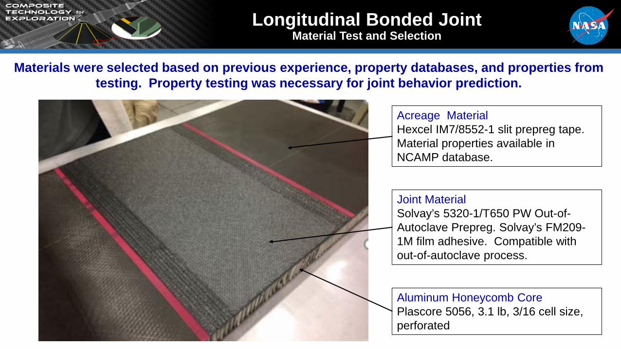
Aluminum Honeycomb CorePlascore 5056, 3.1 lb, 3/16 cell size, perforated
Joint MaterialSolvay’s 5320-1/T650 PW Out-of-Autoclave Prepreg. Solvay’s FM209-1M film adhesive. Compatible with out-of-autoclave process.
Acreage MaterialHexcel IM7/8552-1 slit prepreg tape. Material properties available in NCAMP database.
Materials were selected based on previous experience, property databases, and properties from testing. Property testing was necessary for joint behavior prediction.
Longitudinal Bonded JointMaterial Test and Selection
Longitudinal Bonded JointJoint Trade Study
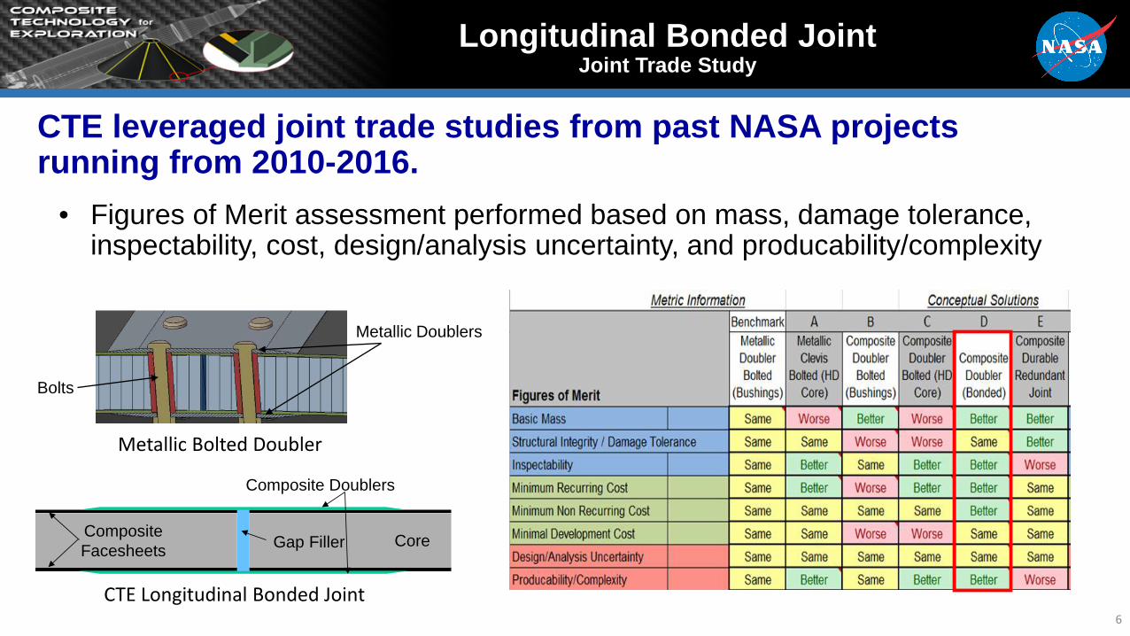
CTE leveraged joint trade studies from past NASA projects running from 2010-2016.
• Figures of Merit assessment performed based on mass, damage tolerance, inspectability, cost, design/analysis uncertainty, and producability/complexity
CTE Longitudinal Bonded Joint6
Metallic Bolted Doubler
Composite Facesheets Gap Filler Core
Composite Doublers
Bolts
Metallic Doublers

Longitudinal Bonded JointSizing and Structural Analysis of Line Loads
Upper ring area with stiffened acreage not considered.
CTE Point Design configuration based on loads, assumed interfaces, and geometry relevant to SLS-scale composite structures. CTE took the highest line load and applied it to the whole joint.
Conic compressive line loads reduce closer to the conic base. CTE chose to design constant joint using the highest load as opposed to designing a continuously variable joint (lighter yet
harder to manufacture and verify).
Axial Compression Line Loadslb/inFocus on composite longitudinal bonded joints for conical
structures such as SLS Payload Adapter (PLA)
Payload Adapter (PLA)
https://www.nasa.gov/exploration/systems/sls/multimedia/images.html
Longitudinal Joint: Panel to Panel Splice
Composite Sandwich Panel

Longitudinal Bonded JointFinal Joint Design
1” Aluminum sandwich core(Plascore 5056 3/16”, 3.1 lb/ft3) 8-ply IM7/8852-1 face sheet
4-ply T650/5320-1 doubler0.005” FM209-1M adhesive
EA9396.MD gap filler
CTE Final Longitudinal Bonded Joint Design
8

Longitudinal Bonded JointManufacturing Process Flow
Composite Facesheets Gap Filler Core
Composite Doublers
CTE Manufacturing Focus• Surface prep technique and process
specs of bonded joints• Manufacturing and machining• NDE Inspection
9
Manufacture acreage sandwich panels
Machine adherends from acreage sandwich panels
Inspect acreage sandwich panels via NDE
Bond sandwich panel adherends together using composite doublers
Inspect bonded joint assembly via NDE
Machine coupons from joint assembly and test
Select surface prep technique
Develop process specifications

10
Longitudinal Bonded JointManufacturing Surface Prep
Several viable options exist for surface prep for adhesively-bondedcomposite joints
• Most commonly used options: manual abrasion, grit blasting, peel ply, plasma treatment• Peel ply was selected for surface prep in longitudinal bonded joint assemblies given project objectives
and timing constraints (234 TFP (PTFE-coated fiberglass weave))
Surface Prep Type Pros Cons
Manual Abrasion Provides for mechanical interlockOperator dependent; poor
repeatability; challenging to scale
Grit Blasting Provides for mechanical interlock; can be operator independent
Challenging (if not impossible) to scale
Peel Ply
Provides for mechanical interlock; operator independent; inherently
repeatable; provides surface protection prior to bonding; scalable
Removal can leave behind potential contaminants
Plasma TreatmentProvides for chemical bonding;
operator independent; scalable; can be closely controlled
Does not provide for mechanical interlock
Single lap shear tests were carried out to evaluate adhesively bonded joint• Failed in a combination of substrate failure (in the laminate) and cohesive failure (in the bulk film adhesive)• Adhesive failure (in the film adhesive) was not prevalent
Shear TestingFailed Specimens

Sandwich Panel Assembly
Following Gap Filler Injection
ManufacturingLongitudinal Bonded Joint
Sandwich Panel Assembly
Undergoing Gap Filler Injection
Composite Doubler Following Lay Up and Installation
Composite Doubler Bag
Cure
Longitudinal Bonded Joint Assemblies
Following Doubler Cure
CTE Longitudinal Bonded Joint Panel Manufacturing Process
11

Longitudinal bonded joint sub-element test coupon models designed to fail at the joint and analyzed to test joint capability and validate structural models.
• Axial Edge-Wise Compression (AEWC) coupon• Hoop Edge-Wise Compression (HEWC) coupon• Hoop Tension (HT) coupon
HT CouponHEWC CouponAEWC Coupon
Longitudinal Bonded JointL-Joint Sub-Element Test Coupon Design
12
CTE Point Designs Line Loads w. 2.0 FS (lb/in)
Axial Compressive, Nx -3,998
Hoop Compressive, Ny -980
Hoop Tension. Ny 906

Longitudinal Joint Test Article Manufacturing
• Jointed panels from MSFC were trimmed and assembled into sub-element test articles at Goddard Space Flight Center. – 19 Axial edge-wise
compression (AEWC) coupons.
– 17 Hoop edge-wise compression (HEWC) coupons.
– 20 Hoop tension coupons.• NDE detected slight flaws in a
few coupons.
Processing
Axial EWC Hoop EWC
Hoop Tension
Bond Ends
Final Trim & Metrology
Longitudinal Bonded JointL-Joint Sub-Element Test Articles
Trim Panels

Failed AEWC Coupon
Load
(lbf
)
End Shortening (in.)
CTE-301-3-AEWC-P-1CTE-301-3-AEWC-P-3CTE-301-4-AEWC-P-2CTE-301-4-AEWC-P-4CTE-301-4-AEWC-P-5
AEWC – PRISTINE COUPONS
LL x 2.0 FS = 24.7 Kips
Average Test Failure Load = 40.45 Kips
Fiber Damage in Face-sheet
AEWC PRISTINE
Longitudinal Bonded JointTesting of Sub-Element Coupons
14
Coupon Type Design Load Limit x 2.0 FS (Kips)
Avg. Test Failure Load (Kips) Pristine/ Impact-Damaged
Pristine - Pre-/ Post- TestCorrelation (%)
AEWC 24.7 40.45 / 31.96 9 / 3
HEWC 6.1 21.42 / 20.42 3 / 3
Hoop Tension 2.7 15.01 / 15.01 1 / 1
Failed HEWC CouponHT – PRISTINE COUPONS
CTE-300-1-HWT-P-1CTE-300-1-HWT-P-2CTE-300-3-HWT-P-1CTE-300-3-HWT-P-2
Load
(lbf
)
End Displacement (in.)
LL x 2.0 FS = 2.7 Kips
Average Test Failure Load = 15.01 Kips
HT PRISTINE
Failed HT CouponHEWC – PRISTINE COUPONS
Load
(lbf
)
End Shortening (in.)
CTE-301-5-HEWC-P-1CTE-301-9-HEWC-P-1CTE-301-9-HEWC-P-2CTE-301-10-HEWC-P-1CTE-301-10-HEWC-P-2
LL x 2.0 FS = 6.1 Kips
Average Test Failure Load = 21.42 Kips
HEWC PRISTINE
Fiber Damagein Face-sheet ply
All coupons failed above CTE Point Design Limit Load (LL) with 2.0 FS.
Joints are damage tolerant.
Pristine, impact-damaged, and NDE-detected flawed sub-element coupon testing was performed.Purpose of sub-element testing:
• Show capability of longitudinal bonded joints for loadings with 2.0 FS (Joint Discontinuity Factor)• Use test data to validate finite element analysis models (FEA) for joint failure load and failure mode prediction

Longitudinal Bonded JointDesign, Analysis, Fabrication, and Test of Large-Scale Panel
1515
Demonstrated scaled-up composite bonded L-joint manufacturing and structural performance (pristine and damaged) by successfully manufacturing and testing two 62” long x 30” wide panels with 62” long x 4.2” wide joints under compressive load conditions. • Tests showed that composite bonded longitudinal joints are predictable
and reliable under buckling load conditions.• Tests showed that composite bonded longitudinal joints, both pristine and
impact-damaged, satisfy design load requirements with 2.9 and 2.4 factors of safety, respectively, and have met fracture critical joint performance requirements.
Buckling Test Buckling Analysis
Failure Test
Failure Analysis
Both panels failed above the CTE Point Design limit load with a 2.0 factor of safety. Buckling initiation occurred at 73.8 and 60 kips. In both panels, failure did not initiate in the joint doubler.
Side rails were added after buckling initiation for both tests to better distribute loading for failure.

• CTE Project has developed and demonstrated composites technologies including materials, design & analysis, manufacturing, and NDE with a focus on longitudinal bonded joints for infusion into future SLS-scale structures.
– Design and analysis process for design of longitudinal bonded joint has been implemented.
– Manufacturing surface prep. technique of using peel ply has been shown that it is viable for use in bonded composite joint fabrication.
– Test results show that CTE bonded joint design exceeds deign loads with joint FS and is damage tolerant
– Analytical correlation results with test data show excellent agreement with joint failure loads and failure modes.
16
Concluding Remarks