composites australia and crc – acs australian composite ... · methodology for wind ... canberra...
TRANSCRIPT
STRUCTURAL REPAIR METHODOLOGY FOR WIND
TURBINE BLADES
Rikard B. Heslehurst, PhDHeslehurst & Associate P/LUniversity of NSW, ADFA
Canberra ACT
Composites Australia and CRC – ACS Australian Composite Conference 2015
Gold Coast, QueenslandApril 2015
Wind Turbine Environment
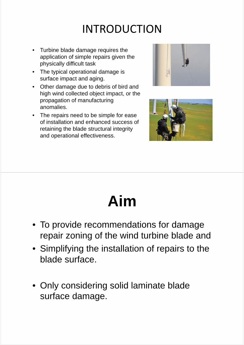
INTRODUCTION
• Turbine blade damage requires the application of simple repairs given the physically difficult task
• The typical operational damage is surface impact and aging.
• Other damage due to debris of bird and high wind collected object impact, or the propagation of manufacturing anomalies.
• The repairs need to be simple for ease of installation and enhanced success of retaining the blade structural integrity and operational effectiveness.
Aim
• To provide recommendations for damage repair zoning of the wind turbine blade and
• Simplifying the installation of repairs to the blade surface.
• Only considering solid laminate blade surface damage.

BACKGROUNDAerodynamic Loading of Wind Turbine Blades
Propeller Spanwise Resultant Force Profile at a Moderate Angle of Attach
0%10%20%30%40%50%60%70%80%90%
100%
0% 10% 20% 30% 40% 50% 60% 70% 80% 90% 100%
Rel
ativ
e F
orce
per
Un
it S
pan
Percentage Distance Hub-to-Tip of Blade
70%
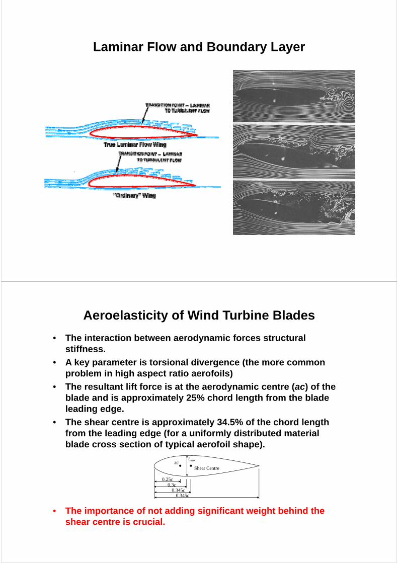
Laminar Flow and Boundary Layer
Aeroelasticity of Wind Turbine Blades
• The interaction between aerodynamic forces structural stiffness.
• A key parameter is torsional divergence (the more common problem in high aspect ratio aerofoils)
• The resultant lift force is at the aerodynamic centre (ac) of the blade and is approximately 25% chord length from the blade leading edge.
• The shear centre is approximately 34.5% of the chord length from the leading edge (for a uniformly distributed material blade cross section of typical aerofoil shape).
• The importance of not adding significant weight behind the shear centre is crucial.
tmax
0.25c
acShear Centre
0.3c0.345c
0.345c
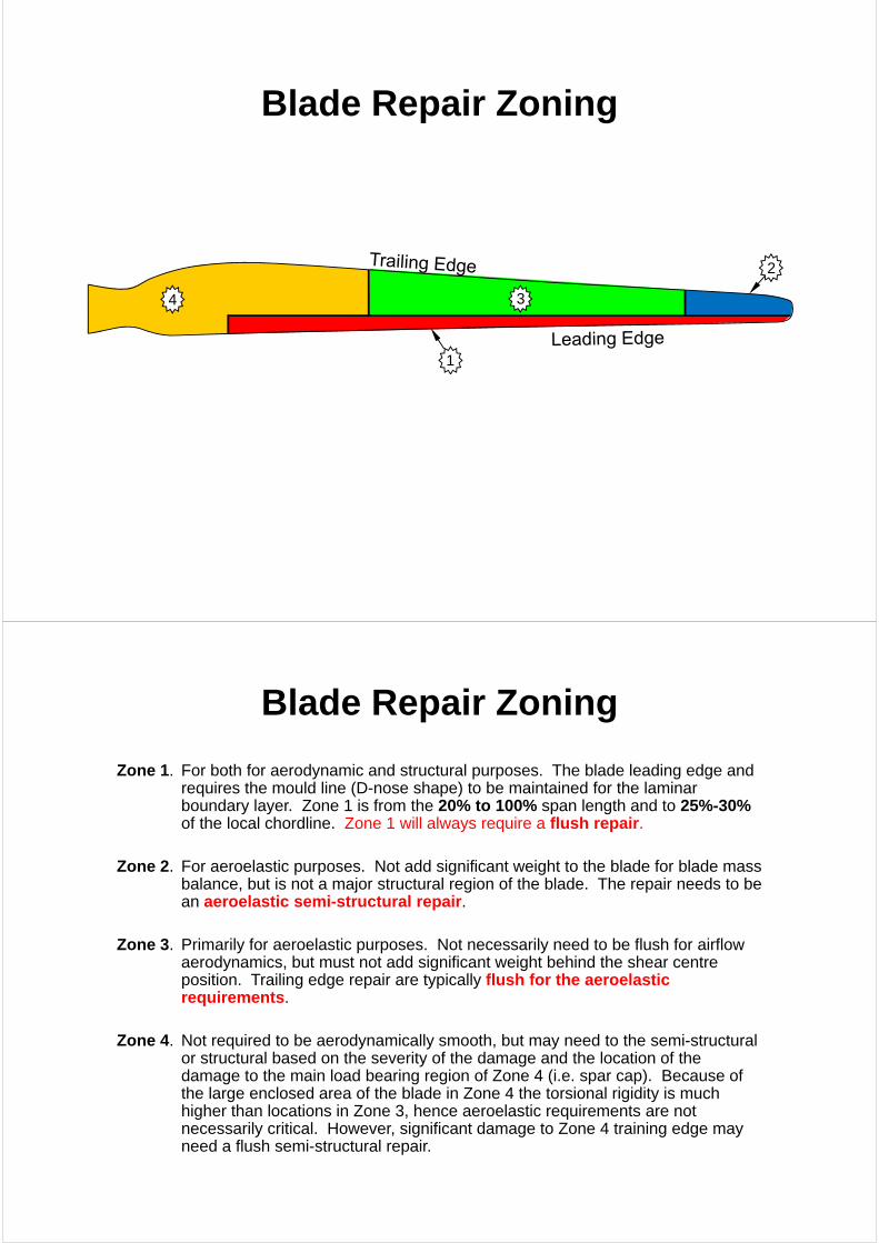
Blade Repair Zoning
1
2
34
Blade Repair Zoning
Zone 1. For both for aerodynamic and structural purposes. The blade leading edge and requires the mould line (D-nose shape) to be maintained for the laminar boundary layer. Zone 1 is from the 20% to 100% span length and to 25%-30% of the local chordline. Zone 1 will always require a flush repair.
Zone 2. For aeroelastic purposes. Not add significant weight to the blade for blade mass balance, but is not a major structural region of the blade. The repair needs to be an aeroelastic semi-structural repair.
Zone 3. Primarily for aeroelastic purposes. Not necessarily need to be flush for airflow aerodynamics, but must not add significant weight behind the shear centre position. Trailing edge repair are typically flush for the aeroelastic requirements.
Zone 4. Not required to be aerodynamically smooth, but may need to the semi-structural or structural based on the severity of the damage and the location of the damage to the main load bearing region of Zone 4 (i.e. spar cap). Because of the large enclosed area of the blade in Zone 4 the torsional rigidity is much higher than locations in Zone 3, hence aeroelastic requirements are not necessarily critical. However, significant damage to Zone 4 training edge may need a flush semi-structural repair.
REPAIR FUNCTIONAL SPECIFICATION
• The basic functional specification requirements are a combination of the customer requirements and engineering specification.
• Utilizing the Quality Functional Deployment (QFD) approach develop a functional specification
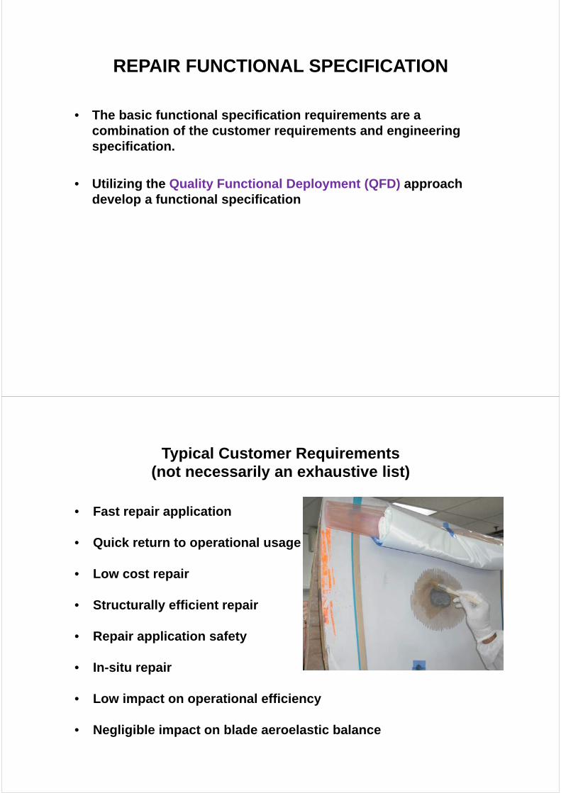
Typical Customer Requirements(not necessarily an exhaustive list)
• Fast repair application
• Quick return to operational usage
• Low cost repair
• Structurally efficient repair
• Repair application safety
• In-situ repair
• Low impact on operational efficiency
• Negligible impact on blade aeroelastic balance
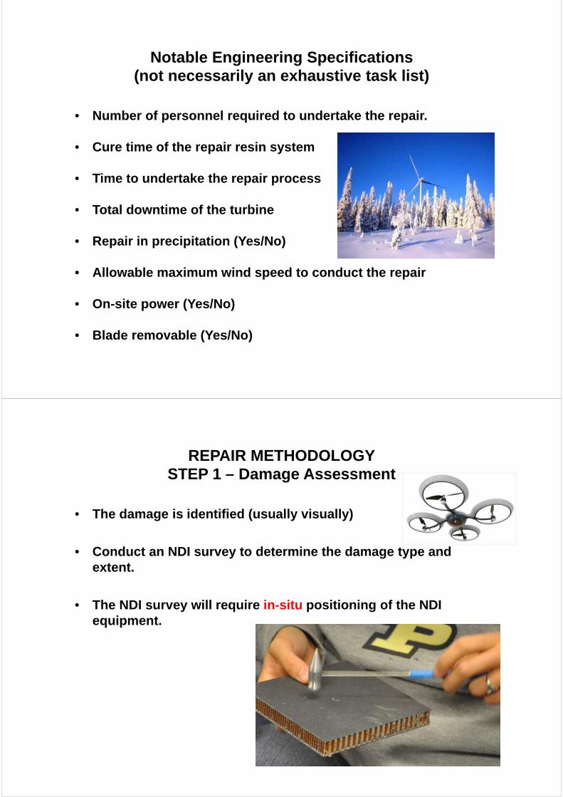
Notable Engineering Specifications(not necessarily an exhaustive task list)
• Number of personnel required to undertake the repair.
• Cure time of the repair resin system
• Time to undertake the repair process
• Total downtime of the turbine
• Repair in precipitation (Yes/No)
• Allowable maximum wind speed to conduct the repair
• On-site power (Yes/No)
• Blade removable (Yes/No)
REPAIR METHODOLOGYSTEP 1 – Damage Assessment
• The damage is identified (usually visually)
• Conduct an NDI survey to determine the damage type and extent.
• The NDI survey will require in-situ positioning of the NDI equipment.
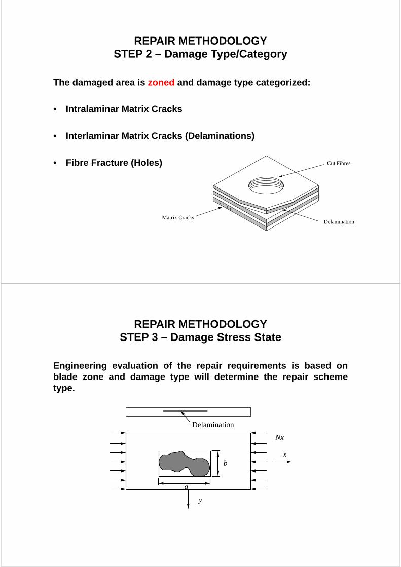
REPAIR METHODOLOGYSTEP 2 – Damage Type/Category
The damaged area is zoned and damage type categorized:
• Intralaminar Matrix Cracks
• Interlaminar Matrix Cracks (Delaminations)
• Fibre Fracture (Holes)
Delamination
Cut Fibres
Matrix Cracks
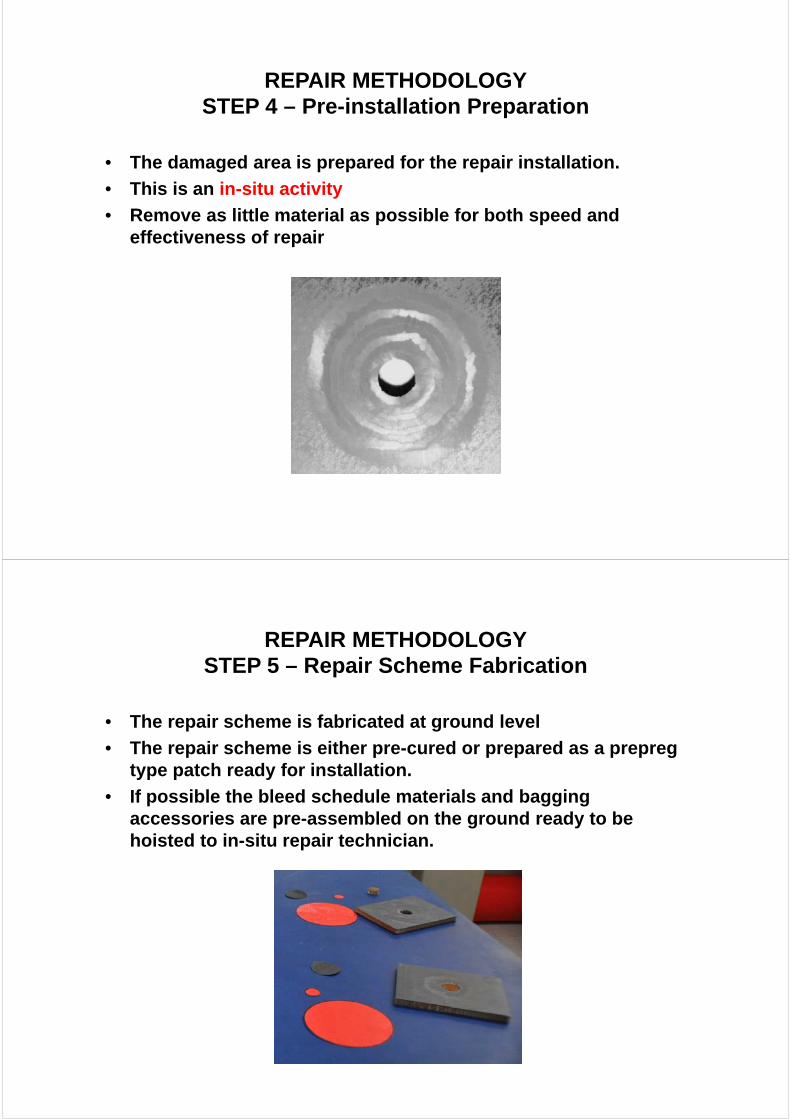
REPAIR METHODOLOGYSTEP 3 – Damage Stress State
Engineering evaluation of the repair requirements is based onblade zone and damage type will determine the repair schemetype.
a
bx
y
Nx
Delamination
REPAIR METHODOLOGYSTEP 4 – Pre-installation Preparation
• The damaged area is prepared for the repair installation.
• This is an in-situ activity
• Remove as little material as possible for both speed and effectiveness of repair
REPAIR METHODOLOGYSTEP 5 – Repair Scheme Fabrication
• The repair scheme is fabricated at ground level
• The repair scheme is either pre-cured or prepared as a prepreg type patch ready for installation.
• If possible the bleed schedule materials and bagging accessories are pre-assembled on the ground ready to be hoisted to in-situ repair technician.
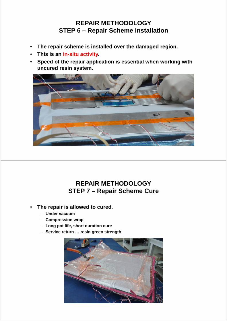
REPAIR METHODOLOGYSTEP 6 – Repair Scheme Installation
• The repair scheme is installed over the damaged region.
• This is an in-situ activity.
• Speed of the repair application is essential when working with uncured resin system.
REPAIR METHODOLOGYSTEP 7 – Repair Scheme Cure
• The repair is allowed to cured. – Under vacuum
– Compression wrap
– Long pot life, short duration cure
– Service return … resin green strength

REPAIR METHODOLOGYSTEP 8 – Post-repair Inspection
• The repaired area is inspected (both visually and approved NDI technique) and blade released for operational requirements.
• This is an in-situ activity.
RECOMMENDED REPAIR SCHEMES
The repair schemes can be generalized as follows:
• Aerodynamic structural
• Aeroelastic semi-structural
• Semi-structural
• Non-aerodynamic structural
• Non-aerodynamic semi-structural
• Non-structural
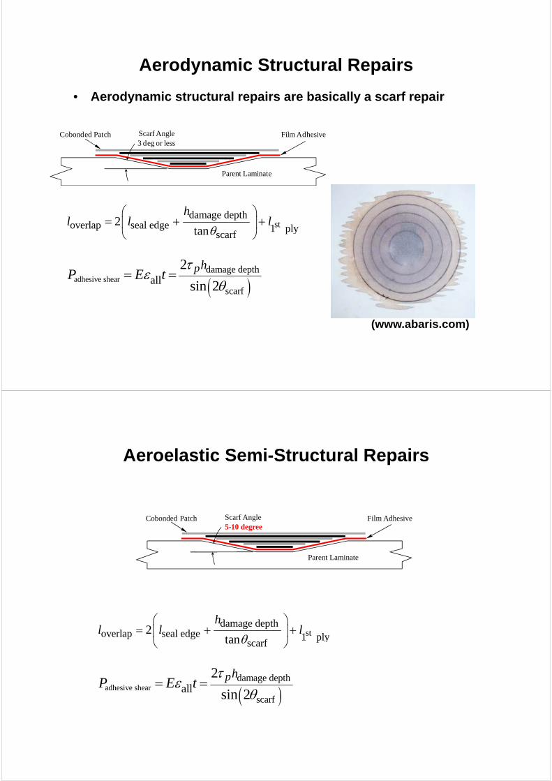
Aerodynamic Structural Repairs
• Aerodynamic structural repairs are basically a scarf repair
(www.abaris.com)
Parent Laminate
Film AdhesiveCobonded Patch Scarf Angle3 deg or less
stdamage depth
overlap seal edge 1 plyscarf
2tan
hl l l
adhesive sheardamage depth
scarfall
2
sin 2ph
P E t
Aeroelastic Semi-Structural Repairs
Parent Laminate
Film AdhesiveCobonded Patch Scarf Angle5-10 degree
stdamage depth
overlap seal edge 1 plyscarf
2tan
hl l l
adhesive sheardamage depth
scarfall
2
sin 2ph
P E t

Semi-Structural Repairs
Damage RemovedLow Modulus Plug
Inverse Structural DoublerAnd Scarf Inlay Film Adhesive
Scarf Angle5-10 degree
scarf depthoverlap doubler plies edge overlap plug
scarf2
tan
hl n l l
maxdoubler adhesive shear adhesive doubler2
2e
pP t Et
Non-Aerodynamic Structural Repairs
Thick Parent Laminate
Metal Patch
MetalBacking Patch
Low Modulus Filler
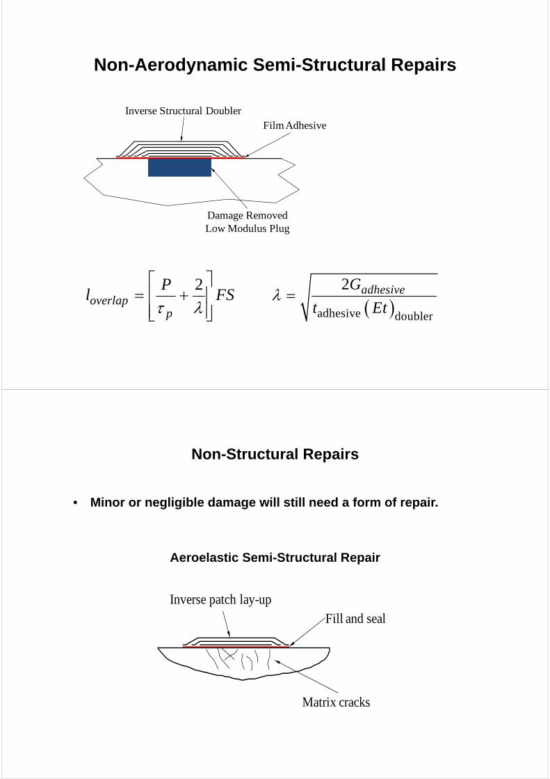
Non-Aerodynamic Semi-Structural Repairs
Damage RemovedLow Modulus Plug
Inverse Structural DoublerFilm Adhesive
2overlap
p
Pl FS
adhesive doubler
2 adhesiveG
t Et
Non-Structural Repairs
• Minor or negligible damage will still need a form of repair.
Aeroelastic Semi-Structural Repair
Matrix cracks
Inverse patch lay-upFill and seal
CONCLUSION• This presentation provides guidelines in the
development of effective and efficient repair schemes for wind turbine blades.
• The repair is process includes a thorough determination of the repair requirements and assessment of the damage state.
• The blades is zoned for specific repair regions.
• A set of repair schemes are provided for better installation efficiencies whilst maintain the structure effectiveness.
CONCLUSION• These repair schemes consider:
thick composite sections at the wind turbine blade hub
aerodynamic contribution of the blade region leading edge.
aeroelastic consideration of trailing edge over a wide blade chord region
• These repair schemes are specifically tailored to solid laminate construction.
• They are be easily adapted to sandwich structure construction.
ACKNOWLEDGEMENT
Thanks to the contribution of Louis Dorworth (Abaris Training, www.abaris.com).
Questions