compound steam engines - heat engines 2 chapter 2 r… · 2 compound steam engines 2.1 introduction...
TRANSCRIPT

2COMPOUND
STEAM ENGINES
2.1 IntroductionA simple steam engine may be defined as one in which each of the engine cylinder
receives steam direct from the boiler, and exhausts into the atmosphere or into a condenser. In modern steam engine practice high pressure steam is used, as the use of such a steam gives greater efficiency, and the plant requires less floor space per unit power developed. But if high pressure steam is used with a large range of expansion in a single-cylinder engine, serious difficulties and disadvantages follow. To overcome the difficulties and obtain certain advantages, compound or multiple-expansion steam engines are built.
Compound engine is one in which the steam from the boiler expands to a certain extent in one cylinder and then exhausts into a larger cylinder, where the expansion may be completed. The first cylinder is called the high-pressure or H.P. cylinder, while the second is called the low-pressure or LP. cylinder. A compound steam engine with two cylinders is called duplex steam engine.
The expansion of the steam may be carried out in three or even four cylinders in succession as in the case of triple expansion or quadruple expansion engines. The H.P. cylinder, in such a case, is that in which the first expansion stage is performed and the L.P. cylinder is that in which the last expansion stage is performed. The cylinders between H.P. and L.P. cylinders are known as intermediate pressure cylinders or I.P. cylinders. Compound steam engines are generally condensing engines.
The main objections to working the high pressure steam through large range of 4 expansion in a single-cylinder are :
... The cylinder must have a large volume for the required amount of expansion and it must be sufficiently strong to withstand safely the maximum pressure. The working parts of the engine have to be made large enough to transmit the maximum load. Therefore, a single-cylinder engine is excessively heavy and costly in proportion to the power developed.
... If the high pressure steam is expanded down to the condenser pressure in one cylinder, the stroke of the piston will be very large.
... The large range of steam pressure (pressure difference) between the initial pressure and exhaust pressure, causes a correspondingly large range of temperature in
-the cylinder. This causes condensation of steam since the high pressure hot steam will come in contact with relatively cold cylinder during admission period. Conden-sation of steam is a source of loss of power and also causes mechanical trouble in the cylinder. The accumulation of water in the clearance space might cause excessive pressure to break the cylinder head.
COMPOUND STEAM ENGINES 31
2J2 AdvantagesThe following are the advantages of multiple-expansion (compound) steam engines :... Temperature range in each cylinder is reduced, with a corresponding reduction in
initial cylinder condensation and temperature stresses. The temperature range is the difference between the highest and lowest temperatures of steam within the cylinder.
... Re-evaporation of moisture at the end of expansion stroke in H.P. cylinderd adds to the live steam supply to L.P. cylinder.
... If simple engine is to utilise the same expansion ratio as a compound engine, its cylinder will have to be made strong enough to withstand the high pressure steam and large enough to accommodate the large volume of low pressure steam at the end of expansion. The thickness required for cylinder walls depends on the maximum pressure to which they are subjected and the diameter of the cylinder. In compound engine the high-pressure cylinder only is subjected to maximum pressure, but its diameter is small. This results in reduction in total weight of cylinders.
... The uniformity of turning moment is improved due to the possible out of phasecrank arrangement (different pistons are coupled to separate cranks) and also dueto the fact that the pressure difference at the beginning and end of the strokes is reduced and in turn reduces the maximum load on the piston.
... Better mechanical balance is achieved, which allows adoption of higher speeds.The higher speed gives improved thermal economy.
... The forces on the working parts are reduced as the forces are distributed over more components of the engine.
... The leakage of steam past the pistons and valves is reduced due to the reduced pressure difference across them.
... The steam can be re-heated after expansion in one cylinder before entering the next cylinder which will reduce cylinder condensation.
... The compound steam engine may start in any position which is an advantage for locomotives and marine engines.
... The engine may be modified to run at reduced load, at the time of breakdown. This is an advantage for marine propulsion.
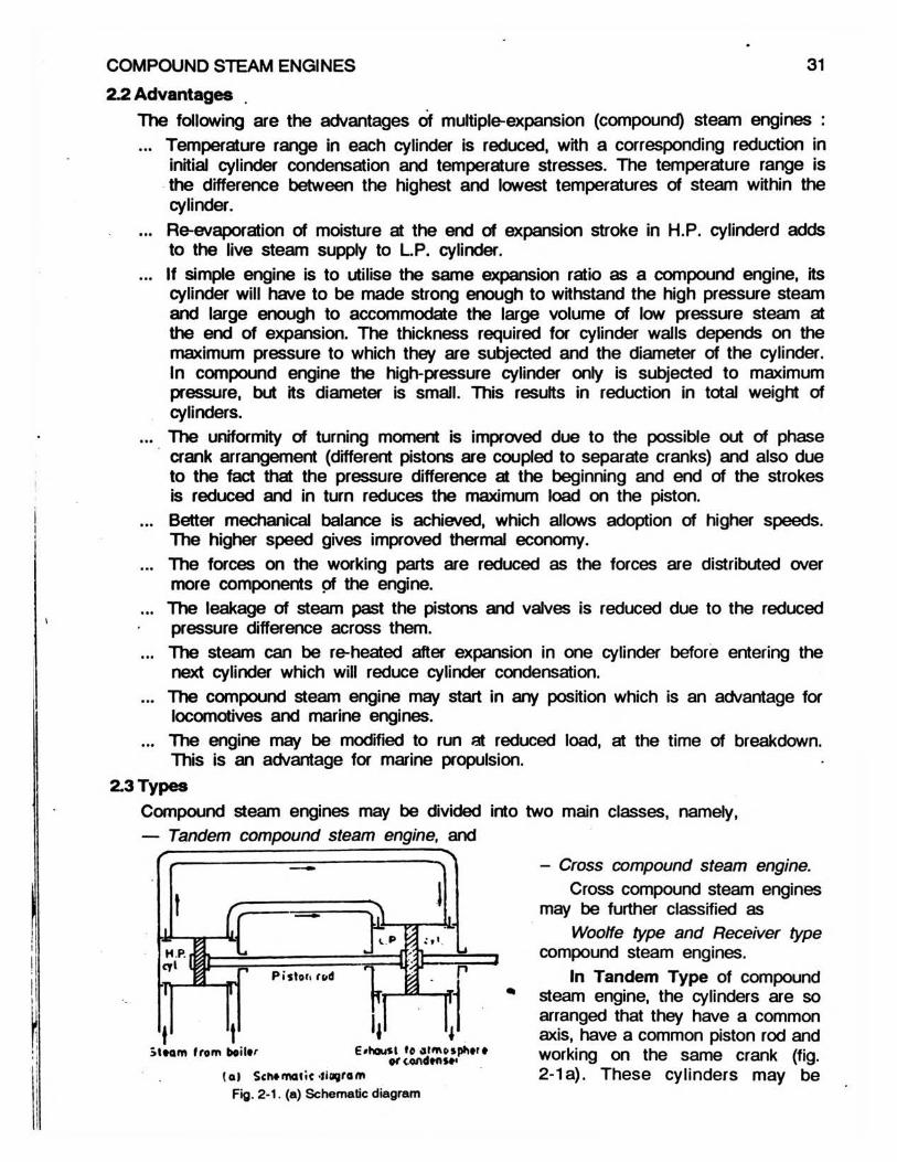
2.3 TypesCompound steam engines may be divided into two main classes, namely,— Tandem compound steam engine, and
- Cross compound steam engine.Cross compound steam engines
may be further classified asWoolf e type and Receiver type
compound steam engines.In Tandem Type of compound
* steam engine, the cylinders are so arranged that they have a common axis, have a common piston rod and
st*am from boiitr working on the same crank (fig.(oi Schematic’tiagram 2-1 a). These cylinders may be
Fig. 2-1. (a) Schematic diagram
32 ELEMENTS OF HEAT ENGINES Vol. II
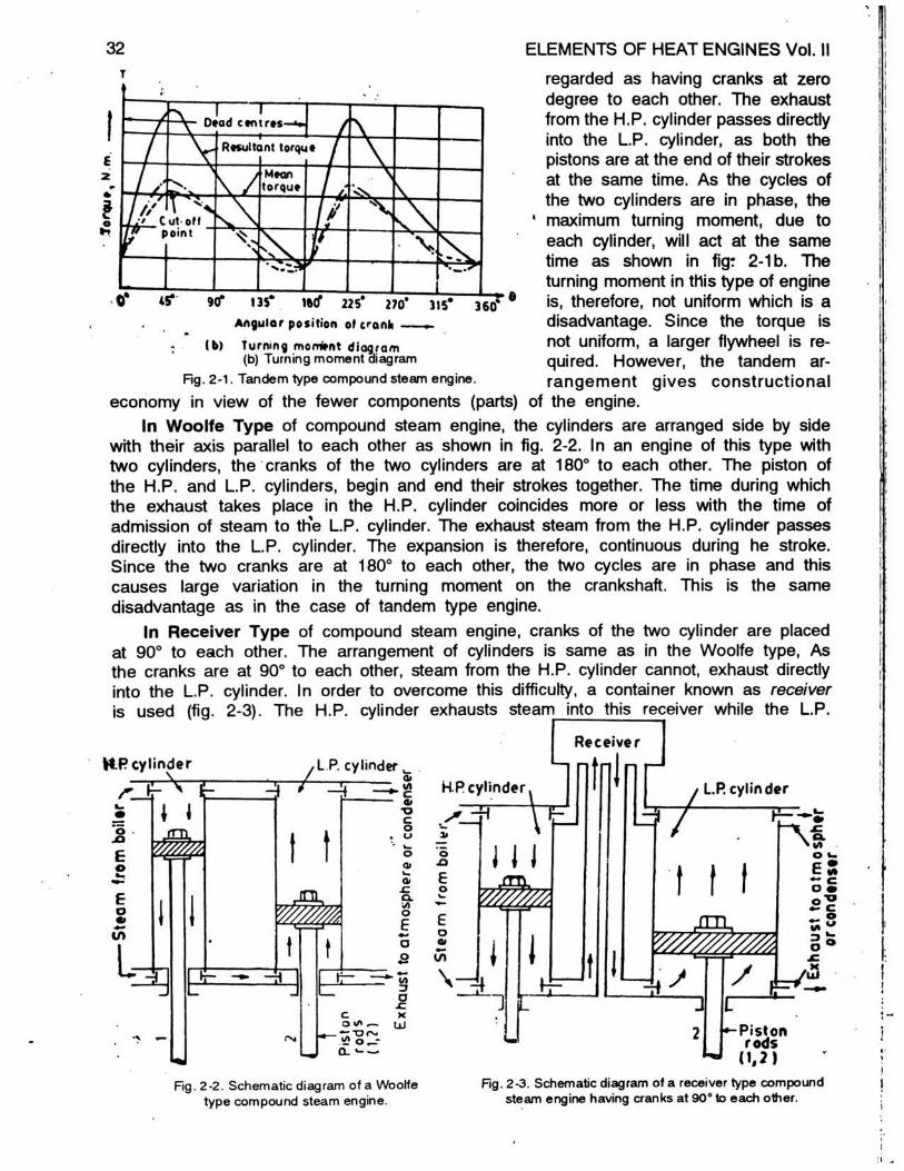
9(f 135* iwf 225* 270*A n g u la r p o s i t i o n of c r a n h —
(b) turning monfrnt diagram (b) Turning moment diagram
regarded as having cranks at zero degree to each other. The exhaust from the H.P. cylinder passes directly into the L.P. cylinder, as both the pistons are at the end of their strokes at the same time. As the cycles of the two cylinders are in phase, the maximum turning moment, due to each cylinder, will act at the same time as shown in fig: 2-1 b. The turning moment in this type of engine is, therefore, not uniform which is a disadvantage. Since the torque is not uniform, a larger flywheel is re-quired. However, the tandem ar-rangement gives constructionalFig. 2-1. Tandem type compound steam engine,
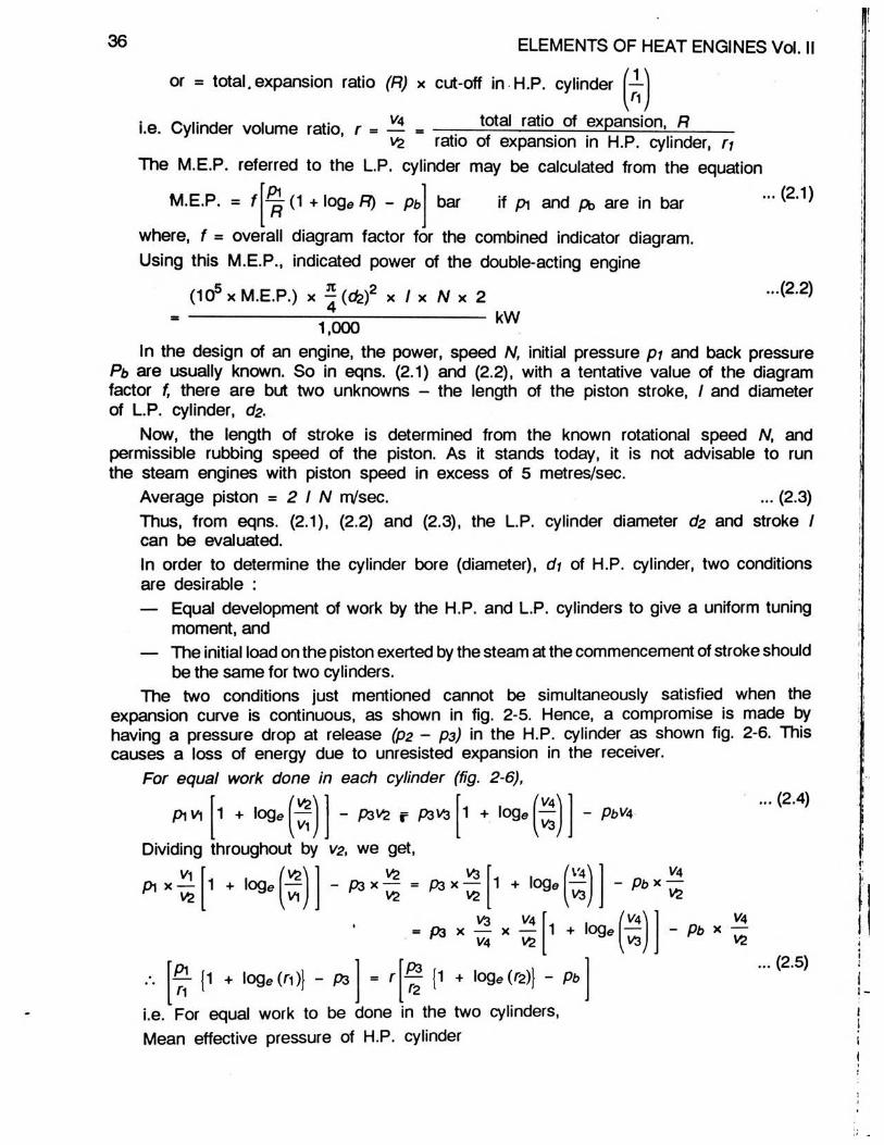
economy in view of the fewer components (parts) of the engine.In Woolfe Type of compound steam engine, the cylinders are arranged side by side
with their axis parallel to each other as shown in fig. 2-2. In an engine of this type with two cylinders, the cranks of the two cylinders are at 180° to each other. The piston of the H.P. and L.P. cylinders, begin and end their strokes together. The time during which the exhaust takes place in the H.P. cylinder coincides more or less with the time of admission of steam to the L.P. cylinder. The exhaust steam from the H.P. cylinder passes directly into the L.P. cylinder. The expansion is therefore, continuous during he stroke. Since the two cranks are at 180° to each other, the two cycles are in phase and this causes large variation in the turning moment on the crankshaft. This is the same disadvantage as in the case of tandem type engine.
In Receiver Type of compound steam engine, cranks of the two cylinder are placed at 90° to each other. The arrangement of cylinders is same as in the Woolfe type, As the cranks are at 90° to each other, steam from the H.P. cylinder cannot, exhaust directly into the L.P. cylinder. In order to overcome this difficulty, a container known as receiver is used (fig. 2-3). The H.P. cylinder exhausts steam into this receiver while the L.P.
H R cylinder
, t V
oJOEo
Eo•>Cn
i 1jm .
/L P. cylinder7 -14 ■ 5
Receiver
l -'=33
t t
E?CO t/t _
.•X’ursi£ o_rQ- w
VI' c *CouI—ow.at.CIX\AO6•-*oow"3a-CXUi
H R cylinder
o.o6o
o atin
\
JJ J J
mm
1 r
c L.R cylinder
/
1 1 1r \ *'U I
/
e SoS5 ?•s W
, K til
Hg. 2-2. Schematic diagram of a Woolfe type compound steam engine.
-Piston rods
(1,2)Fig. 2-3. Schematic diagram of a receiver type compound
steam engine having cranks at 90s to each other.

COMPOUND STEAM ENGINES 33
cylinder draws steam from the receiver. The receiver acts as a reservoir. The resultant turning moment (fig. 2-4a) in the receiver type compound engine is more uniform as the two cycles are out of phase by 90°, which is an advantage. With three-cylinder engine, the cranks are arranged at 120° to each other, which will result in still more uniform turning moment on the engine crankshaft as shown in fig. 2-4b.
lE
z *
3oro
L o w p i
/ /
----------------------------
e s s u r e d
^ V - R e s
% \ t o i
■
l e a d c e
u l t a n t X
r q u e /
i— —
n t r e s - f .
> ] M
\ J 7' N \
i g h \ >
e s s u r eJ K\ t p r )
A \
O W ' \
* s s u ^ , e \7 4
• u
\ /
f x V '
e a n \ >
i r q u e
T /
y /
V '
. \
t \&
% Vht
V * 'f
►V .
X .
; \i
i
•\
X /•
H i g h
\w
p r e s s u
( C e n t r e
/
r e d e a d
s i
. . m
0* 45* 90° 135° 180° 225° 270A ngular position of crank
(a) Two cylinders having cranks at 90* to each other.
I
a/Z3O'
■ f - r — I
R e s u I t a n t t o n
-------------------
u e
\
j /
’ i n
, M e a n t o r q u e
' S j g h p r
i
e s s u r
J
e d e d d c e r i t r e s
f H i !
j h p r e s s u r e c u o f f
\%•
/*
/
■ v
\•
>
■/
/
VV
\>
/ "#
c
* N« «
> V •/
/
k\
\N
/ *0
•
i
) ]4
/
%%
V
/
$
/
\
\
/••/
\V
>
/0
9 ••
\
/
/i /
\%
V
i00
/
\</ •
yh>
•
/
N\ /( \ \
> r\ •
•
A .
I . P . " H . R V L . R
■«*
0* 30* 60* 90* 120° 1 SOT 180* 210° 240° 270* 300* 330* 36CfA ngular position of crank ----------►
(b) Three cylinders having cranks at 120* to each other.Fig. 2-4. Turning moment diagrams of Receiver type compound steam engine.

34 ELEMENTS OF HEAT ENGINES Vol. IIThe receiver should be large enough to keep the pressure in it fairly constant The
volume of receiver should be about 1 -5 times the H.P. cylinder volume. The receiver is often jacketed to reduce condensation and the jacket is supplied with steam direct from the boiler.
The number of cylinders provided in a Multi-cylinder compound steam engine, will depend upon the total range of pressure through which the steam is to be expanded. Simple engines are usually non-condensing with initial pressure ranging from 6 to 7 bar. The two cylinder compound.condensing engines may have initial pressures ranging from 7 to 10 bar and triple expansion engines fromIO to 15 bar. The initial pressure in quadruple expansion engine may be from 15 to 25 bar.
urn
The L.P. release pressure for condensing engine may vary from 0*7 to 0*9 bar and for non-condensing engines may vary from 1-4 to 1-8 bar.
In very large engines, for example, when the diameter of L.P. cylinder exceeds 2-9 metres, it is customary to fit two L.P. cylinders thereby producing a four-cylinder triple expansion engine. One H.P. cylinder and two L.P. cylinders are also used on high speed engines. The famous Webb’s compounded locomotive engine had the reverse of the arrangement, i.e. it had two H.P. cylinders and one L.P. cylinder.
- 2.4 Typical TermsBefore estimation of cylinder dimensions of a compound steam engine, following typical
terms should be understood.Cylinder volume ratio - It is the ratio of the displacement or swept volume of the
low-pressure cylinder to that of the high-pressure cylinder. Where the strokes of the two cylinders are the same, the cylinder volume ratio may be taken as the square of the ratio of cylinder diameters. The cylinder volume ratio in compound steam engines varies from about 2 to 1 to about 8 to 1. %
Total ratio of expansion or ratio of expansion for the whole engine - It is theratio of the final volume of the steam H.P. cylinder.
Free or unresisted expansion -
in the L.P. cylinder to its volume at cut-off in the
It
IT
Fig. 2-5. Combined theoretical indicator diagram for non-receiver type, two cylinder compound steam engine with complete expansion in H.P. cylinder
and incomplete expansion in L.P. cylinder.
is the expansion of the steam in the receiver and passages between cylinders. It is measured by the mean difference between the pressures along the exhaust line of the H.P. cylinder and that along the admission line of L.P. cylinder.
Terminal drop - It is the difference between the pressure in the H.P. cylinder at release and the average receiver pressure.2.5 Estimation of Cylinder Dimensions
The problem of estimation of cylinder di-mensions presents considerable difficulty to be-ginners. Fig. 2-5 represents the hypothetical pressure-volume diagram for the complete ex-pansion in H.P. cylinder in a two-cylinder, non-receiver type, compound steam engine, neglecting clearance and compression.
In the absence of condensation and other losses, L.P. cylinder can be regarded as capable of developing combined power of the H.P. and L.P. cylinders, when supplied with same mass of high pressure steam as originally supplied to

the H.P. cylinder. Thus, combined diagram a b c e f g can be regarded as produced by continuous expansion be in L.P. cylinder, so that the swept volume of L.P. cylinder at cut-off (d c) is equal to the total swept volume of the H.P. cylinder. The average height o f the combined indicator diagram is termed as the mean effective pressure referred to the low-pressure cylinder.' In practice, however, for reasons which will appear later, there is generally a pressure
drop (P2 -P 3) between the high-pressure cylinder release and the receiver, as shown in fig. 2-6. The loss of work due to unresisted expansion in the receiver is shown shaded in fig 2-6. Although this drop of pressure after release of H.P. cylinder is wasteful, yet it is partly counter-balanced by the drying effect on the steam which it produces.Let p 1 = initial steam pressure in bar,
p2 = release pressure in H.P. cylinder in bar, p3 m receiver pressure in bar, p4 m release pressure in L.P. cylinder in bar, pb = condenser pressure in bar, v1 m volume at cut-off in H.P. cylinder in m3, v2 = Volume of H.P. cylinder in m3, v3 = Volume at cut-off in L.P. cylinder in m3,
COMPOUND STEAM ENGINES 35
Fig. 2*6. Combined theoretical indicator diagram for two-cylinder compound steam engine fitted with receiver
and with incomplete expansion in both cylinder. v4 = Volume of L.P. cylinder in m
I = Length of piston stroke in m,N = Speed of the engine in r.p.s., d: = Diameter of H.P. cylinder in m, and
= Diameter of L.P. cylinder in m. Then, neglecting clearance volume,
H.P. cylinder volume, vg X I
and L.P. cylinder volume, va * —(cfe)2 x /
VaCylinder volume ratio or ratio of cylinder volumes, r = —
Ratio of expansion in H.P. cylinder, n vz. viVa
Ratio of expansion in L.P. cylinder, = —
VaRatio of expansion for whole engine or total number of expansion, R - —
As expansion is assumed hyperbolic, p iv j = p2Vg = P3V3 - P4V4 = constant.
Va V4 V\ ( d b \2Cylinder volume ratio, r = — - — x — = —1 V2 VI Vfc Ic fll
04
36 ELEMENTS OF HEAT ENGINES Vol. II
or = total, expansion ratio (R) x cut-off in H.P. cylinder
V4
1
\ /total ratio of expansion, Ri.e. Cylinder volume ratio, r =
V2 ratio of expansion in H.P. cylinder, nThe M.E.P. referred to the L.P. cylinder may be calculated from the equation
M.E.P. = 1 Pi^ (1 + log* R) - pb bar if pi and pb are in bar . . . (2 .1)
where, f = overall diagram factor for the combined indicator diagram. Using this M.E.P., indicated power of the double-acting engine
(105 x M.E.P.) x ^(Cfe)2 x / x N x 2
1,000
...(2 .2 )
kW
In the design of an engine, the power, speed N, initial pressure p i and back pressure Pb are usually known. So in eqns. (2.1) and (2.2), with a tentative value of the diagram factor f, there are but two unknowns - the length of the piston stroke, I and diameter of L.P. cylinder, cfe
Now, the length of stroke is determined from the known rotational speed N, and permissible rubbing speed of the piston. As it stands today, it is not advisable to run the steam engines with piston speed in excess of 5 metres/sec.
Average piston = 2 I N m/sec. ... (2.3)Thus, from eqns. (2.1), (2.2) and (2.3), the L.P. cylinder diameter cfe and stroke Ican be evaluated.In order to determine the cylinder bore (diameter), di of H.P. cylinder, two conditionsare desirable :— Equal development of work by the H.P. and L.P. cylinders to give a uniform tuning
moment, and— The initial load on the piston exerted by the steam at the commencement of stroke should
be the same for two cylinders.The two conditions just mentioned cannot be simultaneously satisfied when the
expansion curve is continuous, as shown in fig. 2-5. Hence, a compromise is made by having a pressure drop at release (p2 - p3) in the H.P. cylinder as shown fig. 2-6. This causes a loss of energy due to unresisted expansion in the receiver.
For equal work done in each cylinder (fig. 2-6),
Pi v\
Dividing
V1
“ (1 + loge (ri)| - p3
1 + loge - P3V2 f P3V3 1 + loge f wV3l
hroughout by V2, we get,
1 + lo9® (t tv i- P3 x — = P3 x —
’ f t ! IS1 * loge m
pbV4
- PbX
... (2.4)
= r
V3 V4 = P3 x — x —
r V4 VS
H (1 + lo g e (r2 )} - pb
1 +
V4VS
- Pb xVAVS
... (2.5)
i.e. For equal work to be done in the two cylinders, Mean effective pressure of H.P. cylinder

COMPOUND STEAM ENGINES 37
s Mean effective pressure of L.P. cylinder x cylinder volume ratio. For equal initial loads on the two piston (fig. 2-6),
(Pi - P3) x |( c f i) 2 (P3 - Pb) x ^ (cfe)2
i.e. pi - P3 « (P3 - pb) m
i.e. pi - P3 - (P3 - Pb) r ... (2.6)Thus, by using eqns. (2.4), (2 5) or (2.6), the value of cylinder volume ratio, r can
be calculated and hence the diameter of H.P. cylinder, duProblem-1 : A compound steam engine develops indicated power o f 147 kW at 1-5 r.p.s. when taking in steam at 9-5 bar and exhausting it at 016 bar. Cut-off in the H.P. cylinder takes place at 045 stroke, and the ratio of low-pressure to high-pressure cylinder volumes is 3-2. Calculate the cylinder dimensions of the engine, Assume an overall diagram factor of 075 and an average piston speed of 2 25 metres per second. The strokes are equal in the two cylinders.
Estimate the fraction of stroke at which cut-off should take place in the L.P. cylinder for approximately equal initial loads on both pistons, and state the resulting receiver pressure. Neglect clearance and assume hyperbolic expansion.
Referring to fig. 2-7,
VI Vd— = 0-45, — = r = 3-2 V2. V£
Total expansion ratio,
* . * m * x * . r x f1 V1 Vz V1
- 3-2 X1 = 7-1
Fig. 2-7.Total indicated power developed by the engine
0-45Average piston speed = 2 I N
i.e. 2-25 = 2 x / x 1 -5 .-. Piston stroke, I = 075 m i.e. 75 cm.
10f> x 2 x f x W1,000 p iv ih + log® V4
V|- PbVA
i.e. 147 = 10° X 2 x 0*75 x 1-51,000 -- -" [9 5 V||1+ loge 7-1) - 0-16 x 7-1 v,]
v<[ • 0 0242 m
NOW, — = 0-45 V2 = 0-45 - 0 0242 x 0-45 = 0 054 m
But, V2 - 5 (^ )2 x I i.e. 0054 = ^ ( d , f x 0-75
Hence (c/i)2 = 0 0917 m2 and dr = 0-303 m, i.e. 30-3 cm (dia. of H.P. cylinder)
*4Now, — = 3-2 v2 x 3-2 = 0 054 x 3-2 = 0-173 m3
38 ELEMENTS OF HEAT ENGINES Vol. II
But, VA = ^ ( d 2f x I i.e. 0-173 = ^(cfc,)2 x 0-75
Hence, (d ,)2 = 0-2937 m2 and d2 = 0-542 m i.e. 54-2 cm (dia. of H.P. cylinder). Considering equal initial loads on the two pistons.
(P i - P3) x ^ ( d i ) 2 - (P i - pb) x ^ (c fe )2
'-e- (Pi - i)2 x I = (Ps - Pb) ^(cfe)2 x I i-e. P y - f r = f a - P b ) ^
i.e. 9-5 - P3 = (P3 - 0-16) 3-2 Receiver pressure, P3 = 2-38 barConsidering points of cut-off in H.P. and L.P. cylinders on hyperbolic curve,
P\V| = P3V3i.e. 9-5 x 0-0242 = 2-38 x v3 Hence, v3 = 0-0966 m3.
Cut-off in L.P. cylinder, « ^ 73* = 0-56 °* stroke-
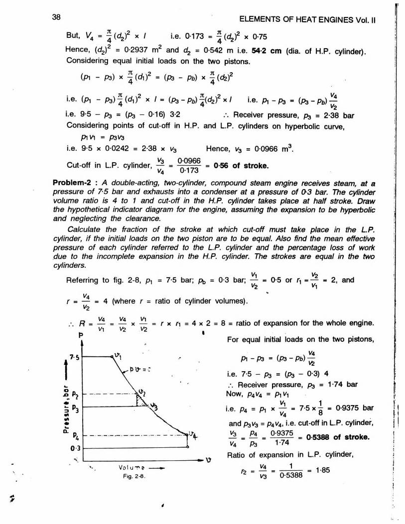
Problem-2 : A double-acting, two-cylinder, compound steam engine receives steam, at a pressure of 75 bar and exhausts into a condenser at a pressure of 03 bar. The cylinder volume ratio is 4 to 1 and cut-off in the H.P. cylinder takes place at half stroke. Draw the hypothetical indicator diagram for the engine, assuming the expansion to be hyperbolic and neglecting the clearance.
Calculate the fraction of the stroke at which cut-off must take place in the L.P.cylinder, if the initial loads on the two piston are to be equal. Also find the mean effectivepressure of each cylinder referred to the L.P. cylinder and the percentage loss of work due to the incomplete expansion in the H.P. cylinder. The strokes are equal in the two cylinders.
V, VoReferring to fig. 2-8, p-| = 7-5 bar; p^ = 0-3 bar; — = 0-5 or j| - — = 2, and
V2 V|%
r ** — = 4 (where r = ratio of cylinder volumes). v2
8 = ratio of expansion for the whole engine.
For equal initial loads on the two pistons,
Pi - P3 = (P3 - Pb)
i.e. 7-5 - P3 = (P3 - 0-3) 4Receiver pressure, p$ = 1-74 bar
Now, P4V4 = P\V-\
i.e. P4 = Pi x — = 7-5 x ^ = 0-9375 bar 14 oand P3V3 = P4V4, i.e. cut-off in L.P. cylinder,
^ = — = ° 9375- = 0-5388 of stroke.V4 P3 1’74
Ratio of expansion in L.P. cylinder,
*2 = — = — --------- 1-8512 V3 0-5388
o va vi A „.-. R - — = — x — = r x n = 4 x 2 = Vi Vz V2
p 1
Fig. 2-8.
*
COMPOUND STEAM ENGINES
Pi
39
Pm h.p. n [1 + log® ri] - p3
7-5 [1 + loge2] -1*74 - 4-61 bar (M.E.P. of H.P. cylinder)
M.E.P. of H.P. cylinder referred to L.P. cylinder
= 4-61 x — = 4-61 x 4 - 1*15 bar.4
Pm ip.P3
V4
[ 1 + loge r2 ] - p b1-74 [1 + loge 1-85] - 0-3 - 1-22 bar.
r2 ‘ ~ 1-85.-. Total M.E.P. referred to L.P. cylinder = 1-15 + 1*22 = 2-37 bar.Work lost due to incomplete expansion in H.P. cylinder is shown by the shaded area of fig. 2*8.Overall M.E.P. (considering whole diagram including shaded area or considering overall diagram) referred to L.P. cylinder
= ^ [ 1 + loge R] - Pb = n r [ 1 + loge 8] - 0-3 = 2-59 bar. .H o
.*. Loss of M.E.P. due to incomplete expansion in H.P. cylinder= 2-59 - 2-37 = 0-22 bar
.-. Percentage loss of work due to incomplete expansion in H.P. cylinder0-22259 x 100 - 8 49%
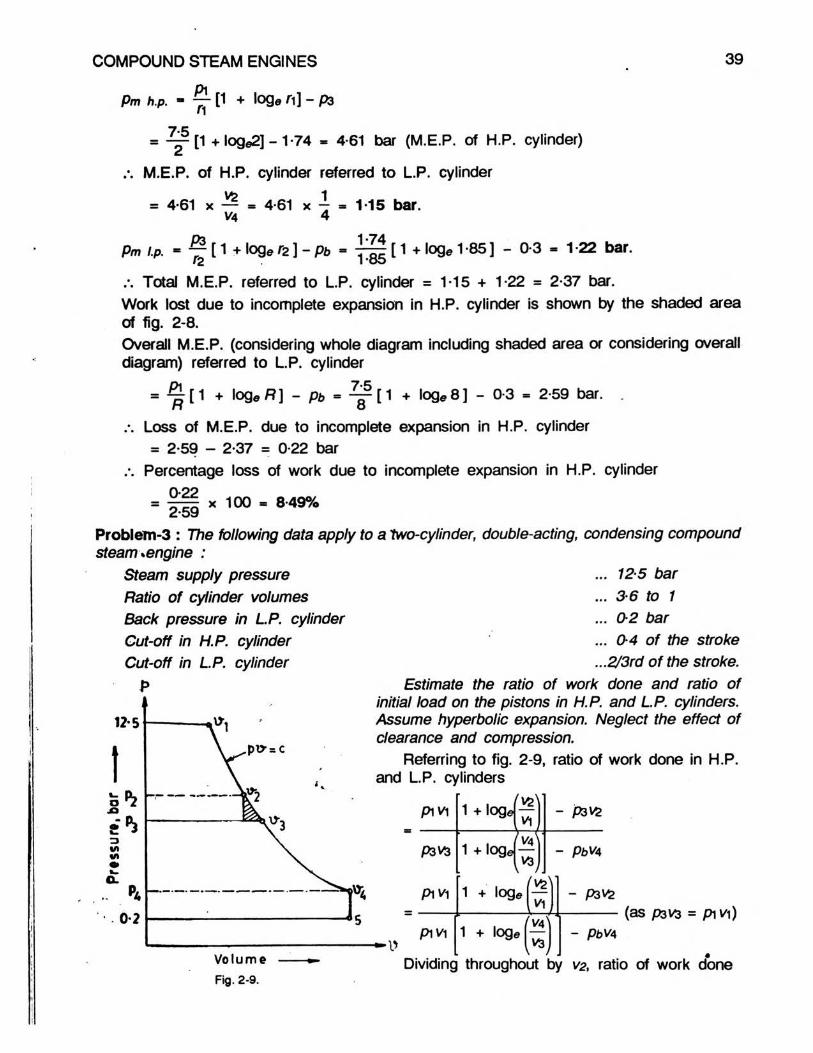
Problem-3 : The following data apply to a 'two-cylinder, double-acting, condensing compound steam *engine :
... 125 bar
... 3 6 to 1
... 0 2 bar
... 04 o f the stroke
...2/3rd o f the stroke.Estimate the ratio of work done and ratio of
initial load on the pistons in H.P. and L.P. cylinders. Assume hyperbolic expansion. Neglect the effect of clearance and compression.
^ Referring to fig. 2-9, ratio of work done in H.P.\ / and L.P. cylinders
Steam supply pressure Ratio of cylinder volumes Back pressure in L P. cylinder Cut-off in H.P. cylinder Cut-off in L.P. cylinder
P
pi vi
P3 V3
p^v^
piviVolume Fig. 2-9.
1 + logel—V\. Va
1 + o g J —^ V3 \
- P3V2
1 + loge a
- PbVA
- P3V2
1 + loge’ VA]
,1*
(as P3V3 = p i^ l)- PbVA
Dividing throughout by V2, ratio of work done
40
1 + loge a I - P3
1 + logefV4
-
Pb x “VS
ELEMENTS OF HEAT ENGINES Vol. II
... (1)
1cylinder volume ratio 3*6
yi u;But, — = cut-off ratio in H.P. cylinder = 0-4, —
VS 1 V4va . 3— = expansion ratio in L.P. cylinder = —
Applying hyperbolic relation, between points of cut-off in H.P. and L.P. cylinders,
P1V| = P3V3 V\ V3i.e. pi x — x * pg x — x V4
i.e. 12*5 x 04 x vz = pa x x V4O
.*. Receiver pressure, p3 = 12-5 X 0-4 X 3 vs2 V4
Substituting the values the eqn, (i), we have,
I 2 5 x Q'4 x 3 x - 2 08 bar 2 3-6
Ratio of work done in H.P. and L.P. cylinders
12-5 x 0-4
12-5 x 0-4
1 +log«
1 log
- 2 081 19
- 0-2 x 3-6
Ratio of initial loads on the H.P. and L.P. pistons is given by
_ ( P ' - P ^ W 2 * 1 ± (p, - g ) . * a 125 - 2-8 „ _ L . r5 4
(P 3 -P d ^ (« )2 (P3 - P b ) ^ ( < k f x l * * 2 - 0 8 - 0 2 . 06
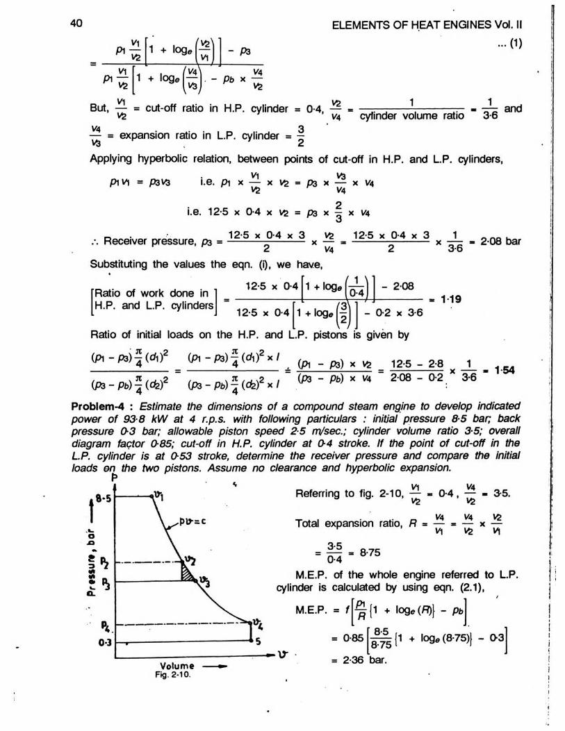
Problem-4 : Estimate the dimensions o f a compound steam engine to develop indicated power o f 93-8 kW at 4 r.p.s. with following particulars : initial pressure 8-5 bar; back pressure 0-3 bar; allowable piston speed 2-5 m/sec.; cylinder volume ratio 3-5; overall diagram factor 0-85; cut-off in H.P. cylinder at 04 stroke. If the point of cut-off in the L.P. cylinder is at 053 stroke, determine the receiver pressure and compare the initial loads &n the two pistons. Assume no clearance and hyperbolic expansion.
P' vyReferring to fig. 2-10, —
vs
pw-ac
0-4,V* 3-5.vs "
VA VA_ _ vV\ vs v\
3-50-4 8-75
M.E.P. of the whole engine referred to L.P. cylinder is calculated by using eqn. (2.1),
M.E.P. = f ^ ( 1 + loge (/=?)} - Pb
= 0-85V
Volume Fig. 2-10.
8-75 = 2-36 bar.
8-5 j1 + log* (8-75)} - 0-3

COMPOUND STEAM ENGINES 41
Using eqn. (2.2), indicated power =2 x 10⁵ x M.E.P. x ^ (Cfe)2 x I x N
1,000kW
(where 2IN = average piston speed = 2-5 m/sec.)
i.e. 93-8 -105 x 2-36 x ^(<fc)2 x 2-5
1,000
(cfe)2 - 0-2025 and cfe = V0-2025 = 0-45 m i.e. 45 cm (dia. of L.P. cylinder)
_ va (c h fCylinder volume ratio, — = h r as stroke of both pistons is same.
v* A
dz 45.-. Diameter of H.P. cylinder, d i = .. ■ . =f= - = = = 24 cm1 Vcylinder volume ratio V35
Piston speed = 2 x I x N = 2-5, i.e., 2 x 1 x 4 = 2 5Hence, I = 0-3125 m, i.e., 31-25 cmUsing hyperbolic relationships for points of cut-off in H.P and L.P. cylinders,
P3V3 = p i vi
i.e. P3
P3 - 8-5 x
V1 V| Vap i X — = p i X — x —r V3 V4 V3
1 1 - 1 83 bar8-75 0-53
Initial load on high-pressure piston p i - P 3 f dA = 8 -5 -1 -83 1tfe = 1-83-0-3 X 3-5
1 24Initial load on low-pressure piston p i - p t
Problem-5 : A double-acting compound steam engine is required to give indicated power of 302 kW at 25. r.p.s with a stream supply at 125 bar and exhaust at 0-3 bar. Take the total number of expansions as .8-4, ratio of cylinder volumes 4 2 to 1, stroke equal to two-thirds o f the L.P. cylinder diameter, overall diagram factor 0-66. Assume hyperbolic expansion and neglect effect o f clearance.
Allowing for a pressure loss of 0-35 bar in the receiver between the two cylinders, find the cylinder diameters, common stroke and L.P. cut-off, if the initial loads on the
two pistons are to be equal.
Referring to fig 2-11, p i = 12-5 bar,
pu-= c
Va VAPb = 0-3 bar, R = — = 8-4, — = 4-2^ v\ vz
Using eqn. (2.1), M.E.P. referred to L.P. cylinder
= f ^ (1 + loge R) - pb
= 0-66 12-5 (1 + loge 8-4)
bar
- 0-3
Volume
Fig. 2-11.
8-4 = 2-87 bar.
yy Using eqn. (2.2), Indicated power
2 x 10⁵ x M.E.P. x ^ (d z f x lx N ________________4 _______1,000 kW
42 ELEMENTS OF HEAT ENGINES Vol. II
i.e., 302 ■2 x 105 x 2-87 x d z f x % cfe x 2-5
1,000
(<fc)3 ■ 0-403 m3 and cfe = vb-403 = 0-738 m, i.e. 738 cm (dia. of L.P. cylinder)dz 0-738Diameter of H.P. cylinder, d i =
2 2Length of piston stroke, I « — cfe - — x 0-738w o
Vcylinder volume ratio 4-2
0-49 m, i.e. 49 cm,
- 0-36 m, i.e. 36 cm
Referring to fig. 2-11, let p3 = admission pressure of L.P. cylinder, then {p3 + 0-35) will be exhaust pressure of H.P. cylinder.Since the initial loads on both pistons are same,
V4p i — (PS + 0-35) = (p3 - pb)vs
i.e., 12-5 - (p3 + 0-35) = (P3 - 0-3) 4-2p3 = 2-58 bar
AS P1V1 = P4V4,
04 « pi X — - 12-5 X - 1-49 bar. r va 8-4Now, P 3 V 3 as P 4 V4
Cut-off in L.P. cylinder, — - —7 V4 /!3
1492-58
0-577 of stroke.
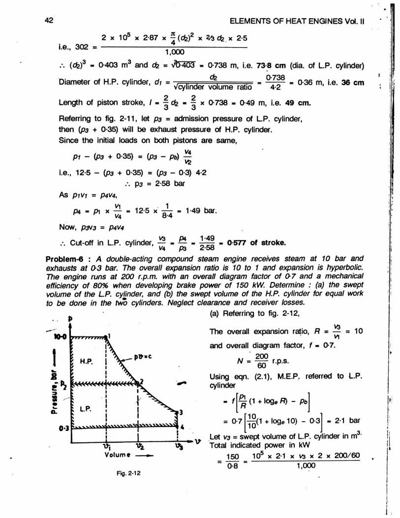
Problem-6 : A double-acting compound steam engine receives steam at 10 bar and exhausts at 0-3 bar. The overall expansion ratio is 10 to 1 and expansion is hyperbolic. The engine runs at 200 r.p.m. with an overall diagram factor o f 0-7 and a mechanical efficiency o f 80% when developing brake power o f 150 kW. Determine : (a) the swept volume o f the LP. cylinder, and (b) the swept volume of the H.P. cylinder for equal work to be done in the two cylinders. Neglect clearance and receiver losses.
(a) Referring to fig. 2-12,
KH>
2
9am w O.
0*3
IX' ! \I i V - p* ’ cJ 1 \f 1 t 1 A
i2
i 1\ 1 ! LP. !: S
^ 5 |3
•1-------------1------------\•
V3The overall expansion ratio, R = — = 10
V\and overall diagram factor, f - 0-7.
« 1 200W = -go r.p.s.
Using eqn. (2.1), M.E.P. referred to L.P. cylinder
[Pif R (1 + log* R) - Pb
= 0-7 ^ ( 1 + loge 10) - 0-3
Volume
•V
2-1 bar
inder in m'.3.Let V3 = swept volume of L.P. cy Total indicated power in kW
150 105 x 2-1 X V3 X 2 X 200/600-8 1,000
.*. V3 - 0*134 m3 (swept volume of L.P. cylinder).(b) For equal work to be done in the two cylinders, neglecting receiver losses, area
of p - v diagram of the H.P. cylinder = area of p - v diagram of the L.P. cylinder.'vs\ , (V3\
- pzvz - pzvz + P 2VSlog® — - P4V3
COMPOUND STEAM ENGINES 43
l.e. pi vi + pi vi log® —
pi vi 1 + log® - pzvz - pzvz 1 + log*■5
- P4V5 ...(0
Since the curve 1 - 2 - 3 is hyperbolic, p iv i - p& 2 Dividing eqn. (0 by p iv i, we have
1 + log® P4V3 ^vsj " P ivi
VS1 V31••• lo9® ITTI - «09a
A log®
.-. 2 014 -
v\f
vs
1 -0-3 x 10
vzx — vi ts
(vs)
0-7
2
10 x 1
i.e. log®
07
(v *r
0 0134 x 0134
00134 + 0134
(as log® 2 014 = 0-7)
07
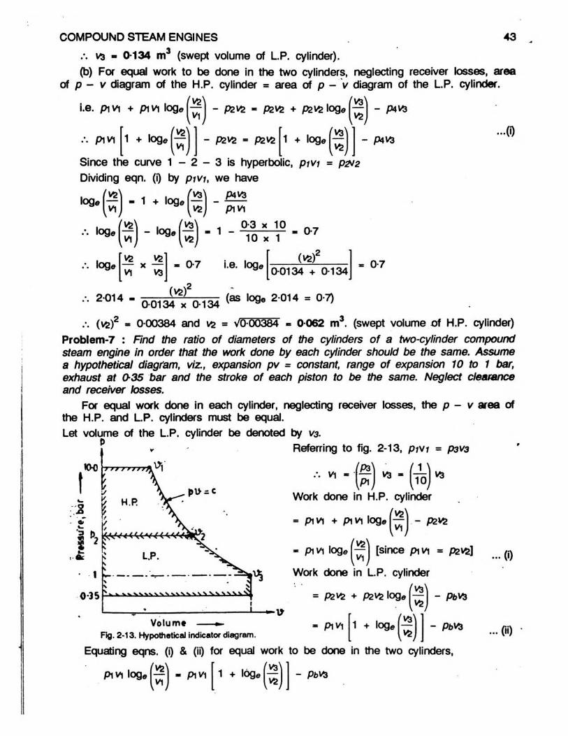
.v (vs) * 0-00384 and vs = VO-00384 - 0-062 m . (swept volume o f H.P. cylinder)Problem-7 : Find the ratio of diameters of the cylinders o f a two-cylinder compound steam engine in order that the work done by each cylinder should be the same. Assume a hypothetical diagram, viz., expansion pv = constant, range of expansion 10 to 1 bar, exhaust at 0-35 bar and the stroke o f each piston to be the same. Neglect clearance and receiver losses.
For equal work done in each cylinder, neglecting receiver losses, the p - v area of the H.P. and L.P. cylinders must be equal.Let volume of the L.P. cylinder be denoted by V3.
P Referring to fig. 2-13, p /vr = p3va
••• * - ( f ) » - (t s ) 19Work done in H.P. cylinder
= p iv i + piV| log®r~J - 02*2
- p iv i log® jS j Isince p iv i = pevsl
Work done in L.P. cylinder'va'
(0
= P2V& + pzvz log®vs
p iv i 1 + log® («)
- PbV*
- P6VJFig. 2-13. Hypothetical indicator diagram.
Equating eqns. (i) & (ii) for equal work to be done in the two cylinders,
00 •
Pi VI lo9« - pi VI 1 + log® - ptvs

44 ELEMENTS OF HEAT ENGINES Vol. II
/. p iv i 1 + logeva v\\— x — V2 V2 - PbV3
Substituting for vi in terms of vq and numerical values of pi and pb, we have,
10 X
i.e. 1 + loge
.*. 2 log®.
1 + log®
_L x 10 /.^ 2
t 1 * * 1 0
= 0-35
V3
(vi>)2= 0 -35 V3
V r M10 [m
■ 10 v*1
o * r
. - 0-65 i.e. loge
1
N 2 ?
f tgV1 0
H .
- - 0-325
e,0-325 0-384 = 0-722
« VT5 x 0-722 - 2-288 (cylinder volume ratio).
Now, — vs
dz
f ( * > 2 * i
* « * ) 2 X /- 2-288
— m V2-288 - 1-51 (ratio of diameters of cylinders)
Problem-8 : A two-cylinder compound, double-acting, steam engine is required to develop brake power o f 58• 75 kW at 6 r.p.s when supplied with steam at 18 bar and exhausting to a condenser at O 18 bar. Cut-off ratio in both the cylinders is to be 04. The stroke length for both the cylinders is 25 cm. Estimate suitable cylinder diameters to 'develop equal riork. Neglect clearance and assume hyperbolic expansion. Take mechanical efficiency as 85% and diagram factor for each cylinder as 08.
Referring to fig. 2-14 for equal work done in both the cylinders,
pi vi . 1 # loge [-—IV*1 - P3V3
Dividing throughout by V2,
P3V3 1 + loge I - PbVA,
PiV±V& 1 + loge — I
ml- P3 * p3
ysVS
Substituting pava = p in ,
1 + logeVA]
V3 - PbVA
V&
1 * loge P - Pi - PiV\
1 + l09 e r r
vi, e - * §
i.e. 18 x
VZ,09® TT " l09« T IV1 V3
vz
* P3 - Pb X
0-4 Jloge 2-5 - loge 2•5 ]
V3j VA
vzVA
- P3 - Pb x —
- PbVA
VZ
Hence, p3 = pb x*• ?3 * Pb * TT * 0VZ ' Z
Considering points of cut-off in H.P. and L.P. cylinders on hyperbolic curve, prv; = P3V3
(0

COMPOUND STEAM ENGINES
P
45i.e., 18 x 0-4vfc = p3 x 0-4v4
VA 18 Vz = p3
vaSubstituting value of — in eqn. (i)vz
P3 « pb XJ 8P3
i.e. (ps) = 0-18 x 18 ps = 1-8 bar.
Indicated power developed in H.P. cylinder 58-75
V 2 x 0-85= 34-56 kW
Fig. 2-14.Work done per stroke in the H.P. cylinder
T4. KG= 2-88 kJ or 2,880 J per stroke.
Work done per stroke in the H.P. cylinder
- 1 0 5 x f pi V|
105 x f x vz
1 + loge
1 + loge
(v z \
p r■ - P3VZ
fVz\Vi
i.e. 2,880 = 10° x 0-8 x V2
vz « 0-0031 m .
But, vz = ^ (< * f x /
18 x 0-4.
- P3
1 + ,09e 04
25
- 1-8
i.e. 0-0031 = * 100
/. « *)z
As shown earlier,
0-0518 and ch = V0-0158V4 18vz " P3
0-125 m i.e. 12-5 cm (H.P. cylinder diameter).
v* volume of L.P. cylinder’ vs * volume of H.P. cylinder
f ( < k f X I
X /- }tfl
iH18P3
dz = d-\ V ~ = 12-5 V 3 ? = 39-53 cm (L.P. cylinder diameter).P3 1 -8Problem-9 : A two-cylinder compound steam engine has an expansion ratio of 9 and the stroke of both cylinders is the same. The cut-off in the high-pressure cylinder takes place at half stroke. The engine is supplied with steam at 7 bar, and the condenser pressure is 0-15 bar. Assuming a common hyperbolic expansion curve for the two cylinders and neglecting effect o f clearance and compression, find the percentage cut-off in the low-pressure cylinder and the receiver pressure so that the work shall be equally distributed between the cylinders.
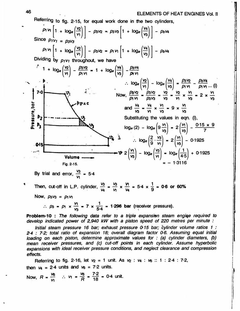
46 ELEMENTS OF HEAT ENGINES Vol. flReferring to fig. 2-15, for equal work done in the two cylinders,
P iv i 1 + loge
Since p1Vl = p3V3
vzvi
P ivi
Dividing1 + log® h r
- P3VZ * P3V3
- P3V2 - Pi Vi
1 + log«
1 + log®
aa
- pbW
- PbV4
by p iv i throughout, we have
1 ♦ K > a .® -VIP3V2 P i VI 1 + loge ( t t I -V3
PbVA Pi VI
vsi*’• ,09e vj” " ,09e
Now, P3VS P3V& Pi V| P3V3
V5IS
^ P3V£ _ P6V4“ P iv i " p i V | ... (i)Vfc V| _ V1
x — - 2 x —VI t s
V[VS V| tS VS
Substituting the values in eqn. (i),
vsv4 v4 V| and — - — x — 9 x
v i' fvilog0 (2 ) - loge 9 - f - 2 1 - f
V3 ts0-15 x 9
(2 tS V|lOQe 1 ^-7 7 1 - 2 - f - 0-1925
rVii9 Vi
VSVolume
Fig. 2-15.
By trial and error, —V|
, ts V|
V9
■ o g ^ to 1925
= - 1 -3 1 1 6
5-4
Then, cut-off in L.P. cylinder, _vsV4
— X — - 5 -4 X -J- « 0 -6 o r 6 0 % V| V4 9
NOW, P3VS = p i vi
P3V| 1Pi x — - 7 x -=-r * 1-296 bar (receiver pressure), vs 5*4 n
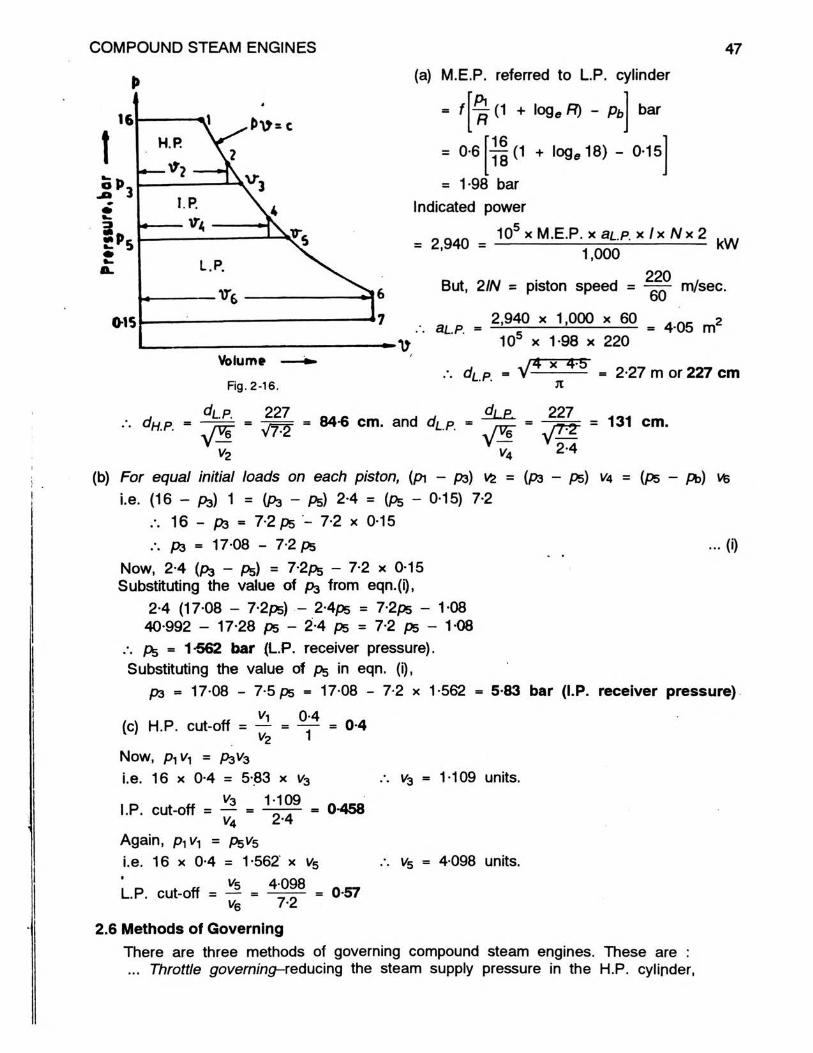
Problem-10 : The following data refer to a triple expansion steam engine required to develop indicated power o f 2,940 kW with a piston speed of 220 metres per minute :
Initial steam pressure 16 bar; exhaust pressure 0-15 bar; cylinder volume ratios 1 : 24 : 7-2; total ratio of expansion 18; overall diagram factor 0-6. Assuming equal initial loading on each piston, determine approximate values for : (a) cylinder diameters, (b) mean receiver pressures, and (c) cut-off points in each cylinder. Assume hyperbolic expansions with ideal receiver pressure conditions, and neglect clearance and compression effects.
Referring to fig. 2-16, let vs = 1 unit. As vz : va : ts :: 1 : 2-4 : 7-2, then V4 = 2-4 units and ts = 7-2 units.
~ vs vsNow, R « — vi -7-2— • = 04 unit.
COMPOUND STEAM ENGINES
P
47(a) M.E.P. referred to L.P. cylinder
= f
= 0-6
Pi— (1 + log e R) - pb
[16
bar
^ ( 1 + loge 18) - 0-15
= 1-98 bar Indicated power
n 105 * M.E.P. X SL.P. X I X N X 2 . . . .= 2,940 = ----------------- . ---------------- kW1,000
But, 2IN = piston speed = 22060 m/sec.
aL.p.2,940 x 1,000 x 60 2■ — ---------------------- = 4-05 m103 x 1-98 x 220
Fig. 2-16.d L.P.
x 4-5
d H.P. =
d L P . 227 . , SLe.- = 84-o cm. and d/_p
Jl
227
= 2-27 m or 227 cm
v 2-4
= 131 cm.V *
V2 V4
(b) For equal initial loads on each piston, (p\ - ps) vs = (P3 - ps) V4 = (ps - Pb) vfei.e. (16 — ps) 1 = {P3 - P5) 2-4 = (ps - 0-15) 7-2
16 - pa = 7-2 ps - 7-2 x 0-1517-08 - 7-2 ps .» (0
Now, 2-4 (P3 - Ps) = 7-2p5 - 7-2 x 0-15 Substituting the value of pa from eqn.(i),
2-4 (17 08 - 7-2ps) - 2-4ps = 7-2ps - 108 40-992 - 17-28 ps - 2-4 ps = 7-2 ps - 108
.*. ps = 1-562 bar (L.P. receiver pressure).Substituting the value of pg in eqn. (i),
P3 = 17-08 - 7-5 ps = 17-08 - 7-2 x 1-562 = 5-83 bar (l.P. receiver pressure)Vi 0-4
(c) H.P. cut-off = — = — = 0-4V"2 1
Now, pyVy = P3V3 i.e. 16 x 0-4 = 5-83 x V3
1-109l.P. cut-off = — = -LzL = 0-458 v4 2-4Again, p,v, = P5V5i.e. 16 x 0-4 = 1-562 x V5
L.P. cut-off = — = = 0-57v6 7-2
V3 = 1-109 units.
1/5 = 4-098 units.
2.6 Methods of GoverningThere are three methods of governing compound steam engines. These are : ... Throttle governing-redudng the steam supply pressure in the H.P. cylinder,

48 ELEMENTS OF HEAT ENGINES Vol. II... Cut-off governing on H.P. cylinder-varying the point of cut-off in the H.P. cylinder,
... Cut-off governing on LP. cylinder-varying the point of cut-off in the L.P. cylinder!In Throttle Governing, the initial pressure in the H.P. cylinder is reduced by throttling
the steam before entering the H.P. cylinder and the points of cut-off in both cylinders
remain unaltered. The effect of this will be to reduce the admission pressure to the L.P. cylinder. Fig. 2-17(a) represents the hypothetical indicator diagram for a two-cylinder compound steam engine where area 1-2-3 -4 is the H.P. cylinder diagram and area 4~3-5-6-7 is the L.P. cylinder diagram.
Let the steam supply pressure be reduced from pr to pr’. The admission to the H.P. cylinder is represented by Y -2 '\ the point of cut-off 2’ must be vertically under 2 , as the cut-off volume is the same. The new expansion curve will now be 2’-3 ’-5 ’ as shown dotted. As the cylinder volume of the H.P. cylinder is the same, exhaust on H.P. cylinder will begin at 3’, where 3* is vertically under 3. The new indicator diagram for L.P. cylinder is represented by 4’-3 ’-5 ’-6 -7 .
It may be noted from fig. 2-17(a) that the effect of throttle governing is to reduce the work done in both the cylinders, the greater reduction taking place in H.P. cylinder. Further, since the governing is by throttling, the steam consumption of the engine in kilograms per hour will follow Willan’s law.
In Cut-off Governing on H.P. Cylinder, the point of cut-off in the H.P cylinder is varied. Referring to fig 2-17(b), 1 -2-3-4 is the H.P. indicator diagram area and 4-3-S -6-7 is the L.P. indicator diagram area at full load. With the decrease of load, the cut-off in the H.P. cylinder takes place earlier, say at point 2’. The expansion in H.P. cylinder is continued upto point 3’ and from 3’ to 5’ in the L.P. cylinder. The exhaust pressure of the H.P. cylinder is reduced. The work done in H.P. cylinder is now given by the area 1—2’- 3 ’- 4 ’p and the work done in the L.P. cylinder is represented by the area 4’-3 ’-5 ’-6 -7 .
It may be noted that the effect of cut-off governing on H.P. cylinder is to reduce the work done in L.P. cylinder, while there is very little change in the work done by the H.P. cylinder. This is because the reduction in H.P. work done due to early cut-off is compensated
and
Volume — »- (a) Throttle governing
Fig. 2-17.
Volume — m(t>) Cut-off governing on
HP cylinder

COMPOUND STEAM ENGINES 49
P P
(o) Loter cut-off (b) Eorlier cut-off
Hg. 2-18. Cut-off governing in L.P. cylinder.
by the decrease of exhaust pressure of H.P. cylinder.From the efficiency point of view, power control by varying the point of cut-off is to
be preferred to throttle governing; because the available pressure drop and hence enthalpy drop is not reduced.
Cut-off Governing on L.P. Cylinder makes very little reduction in the total work done by the engine. Referring to fig. 2-18 (a), let the action of governor cause later cut-off say at a. Thus, the exhaust pressure of the H.P. cylinder is reduced. As the volume of the H.P. cylinder is same as before, there must be a sudden pressure drop at release from 3 to 3’ at constant volume. The area of the H.P. diagram is now1-2-3 -3 ’—4’ and has correspondingly increased. The area of L.P. cylinder is now 4’-a -5 -6 -7 and has correspondingly reduced. This alters the ratio of work done in the two cylinders.
If the cut-off in the L.P. cylinder takes place at a point earlier than point 3 [fig. 2-18(b)], the L.P. cylinder will now take in a small volume of steam; this will increase the exhaust pressure of the H.P. cylinder. But high pressure cylinder steam must expand down to 3, as the cylinder volume is the same; thus, the H.P. cylinder will release against a higher pressure than that in the cylinder. The exhaust stroke will tend to compress the steam back to. 3’ before exhausting along the line 3’-4 ’.
It may be noted that earlier cut-off in L.P. cylinder makes very little difference in the total work produced by the two cylinders together, but the work done by the H.P. cylinder is reduced, while the work done in the L.P. cylinder is increased.
Thus, it may be summarised that governing by controlling cut-off in the H.P. cylinder is the best, from the point of view of maintaining the efficiency of the engine at part loads. As seen earlier, its baS effect is to reduce the proportion of the work done in the L.P. cylinder at part loads. With condensing engines, at very light loads, this may cause the average pressure in the L.P. cylinder to tall below that necessary to overcome the back pressure and frictional resistances, thus reducing the efficiency of the engine.
To• counteract this disparity of work, the cut-off in the L.P. cylinder should take place earlier so as to build up the exhaust pressure of H.P. (or admission pressure of L.P.), thereby increasing the L.P. work at the expense of that of the H.P. This variation in L.P.

50 ELEMENTS OF HEAT ENGINES Vol. IIcut-off will not affect steam consumption or the total work done.
Thus, it is advisable to operate cut-off governing on the H.P. and L.P. cylinders together to achieve the best results.
Tutorial-21. (a) What are the main objections to working the high pressure steam through large range of expansion in
a single cylinder ?(b) What do you mean by a compound steam engine ?
2. (a) Give reasons for compounding steam engines.(b) State the advantages of a compound steam engine as compared to simple steam engine.
3. (a) Classify compound steam engines and state their main characteristics.(b) Explain, with the help of sketches, the working of a receiver type compound steam engine.
4. Explain the following terms as applied to compound steam engines : •(i) cylinder volume ratio, (ii) total ratio of expansion, (iii) free or unresisted expansion, (iv) terminal drop,
and (v) M.E.P. referred to L.P. cylinder.5. What is meant by "M.E.P. referred to L.P. cylinder" ?
In a two-cylinder compound steam engine, the admission pressure ot the H.P. cylinder is 7-5 bar and cut-off takes place at 0-6 stroke. The release pressure in the L.P. cylinder is 0-8 bar. The condenser pressure is 0-2 bar. If the initial loads on the two pistons are equal and expansion curve is assumed tobe hyperbolic, estimate the ratio of cylinder volumes, the mean pressure in the receiver, and the point ofcut-off in the L.P. cylinder.
[Ratio of cylinder volumes = 5-63; Mean pressure in receiver = 1 -3 bar; Cut-off in LP. cylinder = 0-615]6. What are the differences between "cross-compounding" and "WooNe-compounding* of a steam engine ?
Explain this with the help of neat sketches.7. Explain briefly the advantage of compounding in steam engines.
A compound double-acting steam engine develops brake power of 704 kW at 2 r.p.s. when taking in steam at 14 bar and exhausting it at 0-2 bar (20kPa). Cut-off in H.P. cylinder takes place at 0-5 of the stroke and the ratio of cylinder voluqpes is 3-5. Assuming a diagram factor of 0-75, mechanical efficiency of 80 per cent and piston speed of 3 metres per sec., calculate the H.P. and L.P. cylinder diameters and Ihe stroke.
Find the fraction of stroke at which cut-off takes place in L.P. cylinder for equal initial loads on both the pistons. Assume hyperbolic expansion and neglect effect of clearance.
[Dia. of H.P. cylinder = 50 cm; Dia, of LP. cylinder ■ 93 -54 cm; Length of piston stroke = 75 cm; Cut-off in L.P. cylinder = 0-61 ]
8. In a two-cylinder compound steam engine, the admission pressure of H.P. cylinder is 7.5 bar and cut-off takes place at 0-6 stroke. The release pressure in the L.P. cylinder is 0-8 bar and the condenser pressure is 0-2 bar. If the initial loads on the two pistons are equal and the curve of expansion is pv1'2 = constant, estimate the cylinder volume ratio, the mean pressure in Ihe receiver, the point of cut-off in the L.P. cylinder, and Ihe ratio of the work done in the two cylinders.
[Cylinder volume ratio = 3-87; Mean pressure in receiver = 1 7 bar; Cut-off in L.P. cylinder - 0-534; Ratio of work done H.P./L.P. ■ 0-506]
9. Discuss the causes of loss of thermal efficiency in compound steam engines.A compound, double-acting steam engine is required to develop indicated power of 370 kW at 2 r.p.s.
The steam supply is at 8.5 bar and the condenser pressure is 0-3- bar, Cut-off in HP. cylinder takes place at 0-4 of stroke, ratio of cylinder volumes is 3-5, piston speed is 2-5 metres per sec. and diagram factor is 0-85. If the cut-off in L.P. cylinder takes place at 0-475 of the stroke, determine the dimensions of thecylinders, and compare the initial loads on the two pistons. Assume hyperbolic expansion and neglectclearance.
[Stroke = 62-5 cm; Dia. of H.P. cylinder = 47-78 cm; Dia. of L.P. cylinder = 89-4 cm; Ratio of initial loads; H.P./L.P. = 1.052]
10. The following data refer to a double-acting compound steam engine required to give brake power of 299-4kW at 3-33 r.p.s. (200 r.p.m.) with a mechanical efficiency of 80% :
Steam supply pressure, 15 bar; back pressure, 0-3 bar; cut-off in H.P. cylinder, at 0-4 stroke; total ratioof expansion, 10; piston speed, 200 metres/min; overall diagram factor, 0-75.
Assuming equal initial loading on each piston, determine : (i) the H.P. and L.P. cylinder diameters, (ii) the piston stroke, (iii) the receiver pressure, (iv) Ihe release pressure in L.P. and H.P. cylinders; (v) Ihe cut-off in LP. cylinder, (vi) the mean effective pressure in H.P. cylinder (vii) Ihe mean effective pressure

COMPOUND STEAM ENGINES 51in L.P. cylinder, (viii) the overall mean effective pressure referred to L.P. cylinder considering overall diagram, (ix) the mean effective pressure of each cylinder referred to Ihe L.P. cylinder, (x) the total mean effective pressure referred to L.P. cylinder, (xi) the percentage loss of work due to incomplete expansion in the H.P. cylinder, and (xii) the ratio of work done in the two cylinders.
Assume hyperbolic expansion and H.P. diagram factor = L.P. diagram factor = overall diagram factor. Neglect effect of clearance.
[(i) D .h .p = 32 cm, D l ,p ,= 64 cm; (ii) 50 cm; (iii) Receiver pressure = 3-24 bar; (iv) Release pressures, L.P. = 1 -5 bar, H.P. = 6 bar; (v) 0-463 of stroke; (vi) 6-19 bar (vii) 1 -76 bar; (viii) 3-49 bar;
(ix) H.P. m.e.p. = 1-55 bar, L.P. m.e.p. = 1-76 bar (x) 3-31 bar;/ UD 1
(xi) 5-16%; (xii) Ratio of work done, - t t t ]L. r i I'lw11. The following particulars relate to a non-condensing compound steam engine : H.P. cylinder bore, 40 cm;
L.P. cylinder bore, 75 cm; stroke of each piston 100 cm; steam supply pressure; 15 bar; back pressure,1-5 bar; cut-off in H.P. cylinder, 0-55 stroke; cutoff in L.P. cylinder; 0.35 stroke; speed; 3 r.p.s. Take adiagram factor of 0-65 for each cylinder, assume hyperbolic expansion and neglect effect of clearance.Estimate : (a) the pressure drop at release in H.P. cylinder, and (b) the indicated power of each cylinder.
((a) 1-55 bar; (b) Indicated power of H.P. cylinder = 317-43 kW, Indicated power of L.P. cylinder = 572-56 kW]12. Distinguish between Woolfe compound steam engines and receiver compound steam engines.
A compound steam engine is to develop indicated power of 93-75 kW at 1-83 r.p.s, Steam is supplied at 7-5 bar and condenser pressure is 0-2 bar. Assuming hyperbolic expansion and total expansion ratio of 15, a diagram factor of 0-7 and neglecting clearance and receiver losses, determine the diameters of theH.P. and L.P.cylinders so that they may develop equal power. Stroke of each piston is equal to L.P. cylinder diameter.
• [Dia. of H.P. cylinder = 38-65 cm; Dia. of L.P. cylinder = 65-5 cm]13. A compound steam engine receives steam at a pressure of 9 bar and exhausts into 1he condenser at 1
bar. The L.P. cylinder release pressure is 2 bar and the stroke of each piston is the same. Assuming hypothetical indicator diagram, find the ratio of cylinder diameters, if the work done in the two cylinders is equality shared. Neglect clearance and receiver losses.
11-28]14. Find the ratio of the diameters of the cylinders of a two-cylinder compound steam engine in order that the
work done by each cylinder should be the same. Assume a hypothetical indicator diagram, viz pv = constant, range of expansion 9-5 to 2 bar and exhaust at 1 bar, and the stroke of each piston to be the same. Neglect clearance and receiver losses.
(1-304]15. A compound steam engine is to develop indicated power of 120 kW at 2.3 r.p.s. The steam supply is at
8-5 bar and the condenser pressure is 0-3 bar. Assuming hyperbolic expansion and total ratio of expansion of 6, a diagram factor of 0-7, calculate the H.P. and LP. cylinder diameters so that 1he power is equally divided between the two cylinders. Stroke of each piston may be taken equal to 1-2 times the diameter of L.P. cylinder. Assume no pressure drop at release in H.P. cylinder and neglect effect of clearance.
(Dia. of H.P. cylinder = 36-8 cm; Dia. of L.P. cylinder = 47-4 cm]16. In a two cylinder compound steam engine, the ratio of cylinder volumes is 5 and the totaf ratio of expansion
is 10. The initial steam pressure is 10 bar and the back pressure is 0-4 bar. Assuming a common hyperbolic expansion curve for the two cylinders and equal distribution of work between the cylinders compare the initial loads on the pistons. Neglect the effect of clearance and compression. [equal]
17. A triple-expansion steam engine is required to develop indicated power of 3,750 kW at 1.5 r.p.s. under the following conditions :Pressure in H.P. steam chest ... 14 bar
0-7 stroke 3-67 m per sec. 700 mm of Hg 760 mm of Hg
Cut-off in H.P. cylinder Average piston speed Vacuum Barometer '
Using ratio of cylinder volumes of 1 : 3 : 7-5 and a diagram factor of 0-63, determine the dimensionsof the cylinders. If the initial loads on the pistons are equal, estimate the mean receiver pressures for theengine. Assume hyperbolic expansion and neglect effect of clearance.
[Dia. of H.P. cylinder = 80 cm, Dia. of l.P. cylinder = 138-5 cm, Dia of L.P. cylinder = 219 cm;Length of stroke = 122 cm; Mean receiver pressure in 1 st receiver = 4-5 bar,
, Mean receiver pressure in 2nd receiver = 1-345 bar]

52 ELEMENTS OF HEAT ENGINES Vol. II18. Estimate the diameters of the cylinders for a quadruple expansion marine steam engine to develop indicated
power of 9,000 kW with a piston, speed of 5 metres per second under the following conditions :Pressure in steam chest 16 bar; condenser pressure 0-15 bar; total ratio of expansion 14; overall
diagram factor 0-65.Rnd also the point of cut-off in the H.P. cylinder. Assume hyperbolic expansion with ratio of cylinder
volumes of 1 : 2 - 1 : 4-4 : 9. Neglect effect of clearance.[Dia. of H.P. cylinder = 99 cm; Dia. of 1st I.P. cylinder = 143-5 cm; Dia. of 2nd I.P. cylinder = 208 cm;
Dia. of L.P. cylinder = 297 cm; Cut-off in H.P. cylinder = 0-643]19. (a) What are the various methods of governing employed in compound steam engines ?
(b) What will be the effect of the following on the distribution of power between the two cylinders of acompound steam engine.(i) Varying the cut-off in H.P. cylinder,(ii) Varying the cut-off in L.P. cylinder, and(iii) Throttling of inlet steam.Explain with the help of suitable diagrams wherever necessary.
20. What are the main factors to be considered in deciding the sizes of the cylinders in a compound steam engine ?
21. Explain briefly the effect on the distribution of the work between the two cylinders when governing is carried out(a) by throttling, and(b) by cut-off.