comprehensive tool set for operations and engineering 4k ...comprehensive tool set for operations...
TRANSCRIPT
1
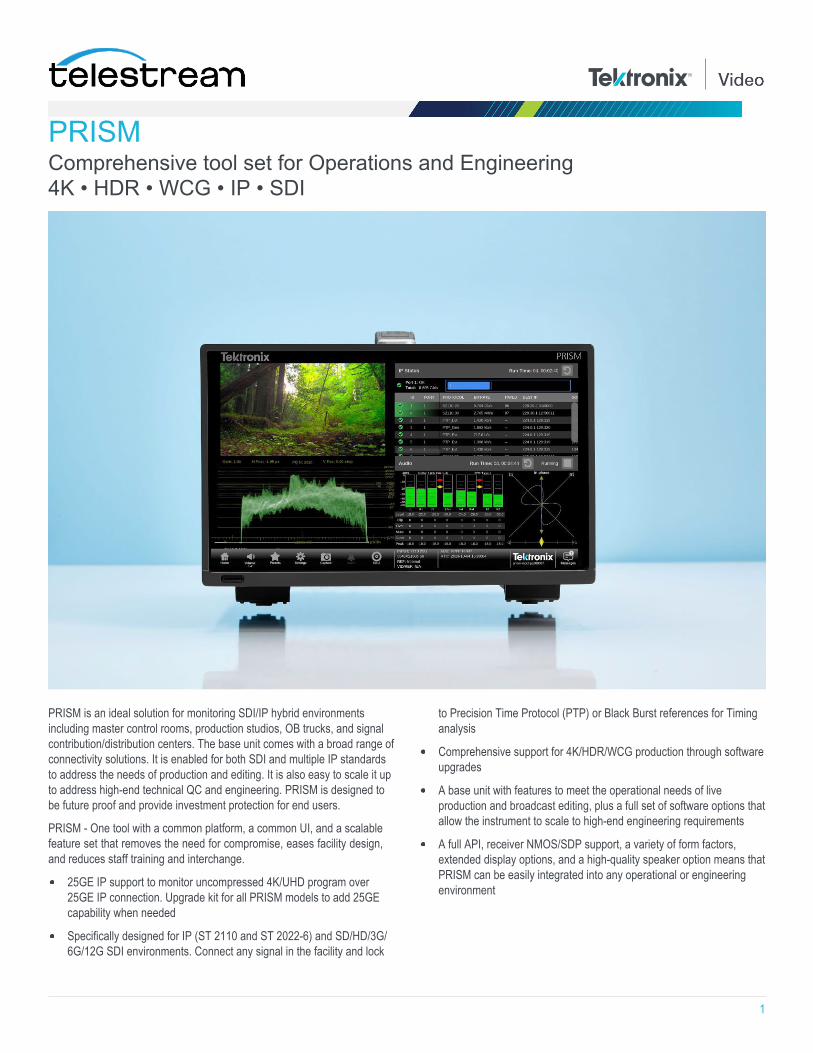
PRISM Comprehensive tool set for Operations and Engineering 4K • HDR • WCG • IP • SDI
PRISM is an ideal solution for monitoring SDI/IP hybrid environments including master control rooms, production studios, OB trucks, and signal contribution/distribution centers. The base unit comes with a broad range of connectivity solutions. It is enabled for both SDI and multiple IP standards to address the needs of production and editing. It is also easy to scale it up to address high-end technical QC and engineering. PRISM is designed to be future proof and provide investment protection for end users.
PRISM - One tool with a common platform, a common UI, and a scalable feature set that removes the need for compromise, eases facility design, and reduces staff training and interchange.
25GE IP support to monitor uncompressed 4K/UHD program over 25GE IP connection. Upgrade kit for all PRISM models to add 25GE capability when needed
Specifically designed for IP (ST 2110 and ST 2022-6) and SD/HD/3G/ 6G/12G SDI environments. Connect any signal in the facility and lock
to Precision Time Protocol (PTP) or Black Burst references for Timing analysis
Comprehensive support for 4K/HDR/WCG production through software upgrades
A base unit with features to meet the operational needs of live production and broadcast editing, plus a full set of software options that allow the instrument to scale to high-end engineering requirements
A full API, receiver NMOS/SDP support, a variety of form factors, extended display options, and a high-quality speaker option means that PRISM can be easily integrated into any operational or engineering environment

2
PRISM Datasheet
Using PRISM in your workflow
Production
Make quick and accurate decisions on set with Prism features designed for the camera operator
Modern productions enhanced with High Dynamic Range (HDR) and Wide Color Gamut (WCG) technologies mean there are less opportunities to fix content in Post. Production teams must get it right at acquisition to avoid a costly reshoot. Lighting engineers, cinematographers, and directors need tools that enable quick scene creation, camera setup, and editing decisions to minimize the time on set. PRISM offers a patented Stop display with trace that linearly responds to what you see on set. Luminance false color will help you identify objects in shadows, highlights, and with certain skin tones to simplify camera setup and quickly capture proper footage. PRISM provides you the tools to help you quickly get it right first time and to provide clean, objective communication across the whole creative team.
Live production
Prism's array of features ensure that content that is produced within the truck is high quality regardless of format
Live production is all about one shot to get live action, high value content captured and delivered in the highest possible quality, in multiple formats for delivery to viewers in multiple ways. Increasingly, live production teams are required to deliver both 4K/HDR/WCG and HD/Standard Dynamic Range (SDR)/BT.709 content simultaneously. Ensuring that both feeds have a consistent look and are high quality is a real challenge.
PRISM provides the tools required to handle live production. For traditional productions there are expected tools including waveform, vector, lightning, and diamond displays. For 4K/HDR/WCG, PRISM introduces new and innovative displays. Stop display with a Nits scale has trace that linearly corresponds with what the operator sees in a reference picture monitor and it makes setting the black, white, and gray levels and controlling the specular highlights easy. Picture display has luminance false color option to identify objects in different exposure zones, so operators can easily adjust the camera iris to, for example, set a white line in a green grass field to the 90% reflectance zone. PRISM also provides CIE charts and 3D LUT conversions in picture displays for color management for HDR/WCG content creation.

PRISM Datasheet
3
Post production
An instrument for objective quality assessment, enabling consistent and efficient workflows
Post production workflows are challenged with creating great looking and sounding content as quickly and efficiently as possible. Increasingly, creatives are required to master content for multiple end points, ranging from SD/SDR/709 for DVD to 4K/HDR/2020 for VOD, while maintaining artistic integrity and a consistent look.
PRISM can simplify the work to create, grade, and Quality Control (QC) the content in a single workflow regardless of the mastering format. There is support for a wide range of HDR standards, 4K formats, and tools allowing objective ways to monitor and measure content. This allows operators to check luma, color and audio levels for a variety of formats and standards. PRISM is equipped with Waveform, Vector, and Diamond displays, and editors can extend the use of these familiar tools for HDR/WCG editing. It also offers the practical maximum/minimum luminance levels and contrast ratio defined by the brightest/darkest area percentage that allows editors to mange the look of the scene objectively. The picture area percentage outside of ITU-R BT.709 or DCI-P3 gamut indicates the picture region possibly impacted by HDR/WCG to SDR/709 conversion. PRISM provides an innovative tool set for unique challenges in multiple formats to maximize the degree of creativity and make quality control easier.
Broadcast engineering and R&D
A tool with trusted measurements for both SDI and IP technology
Broadcast and R&D engineers are faced with a level of change and technology transition never seen before. They need tools that enable them to see and solve network or design issues quickly and effectively, whether they are working in an SDI or IP environment. As standards change engineers require tools that will evolve as the standards evolve, a range of options that allow them to configure the instrument to meet their needs, and a comprehensive set of tests and measurements they can trust.
PRISM connects to a variety of signals in the facility or laboratory such as; SD/HD/3G/6G/12G-SDI, ST 2110-20/30/40, ST 2022-6, ST2022-7, ST 2059 (PTP), and NMOS IS-04 and IS-05. Coupled with the connectivity is a comprehensive set of displays and measurements that are designed to provide information they need to find and solve problems. The instrument provides IP Statistics, PTP Timing analysis, Video session displays, Black Burst to SDI timing, and 12G-SDI Eye pattern measurement. PRISM also provides specialized measurements such as ST 2110-21 buffer analysis to understand what happens to the system under different traffic flow situations. Generator functionality provides a series of known test pattern for testing in ST 2110 or SDI formats. An API allows PRISM to be connected to control systems for remote monitoring applications.
PRISM Datasheet
4
Innovative feature set for HDR/WCG content creation
Multiple false color modes in picture display
CIE chart display
Stop display (stop, nits)
Input transfer function/color space conversion
Diamond/Lightning display
HDR Measurement Quickly check objects in HDR Picture display gives operators luminance and color information of the objects in a scene. However, relying on the Picture display during HDR productions can lead to overly bright images. What gets created is "brighter SDR pictures" rather than "pleasing HDR pictures".
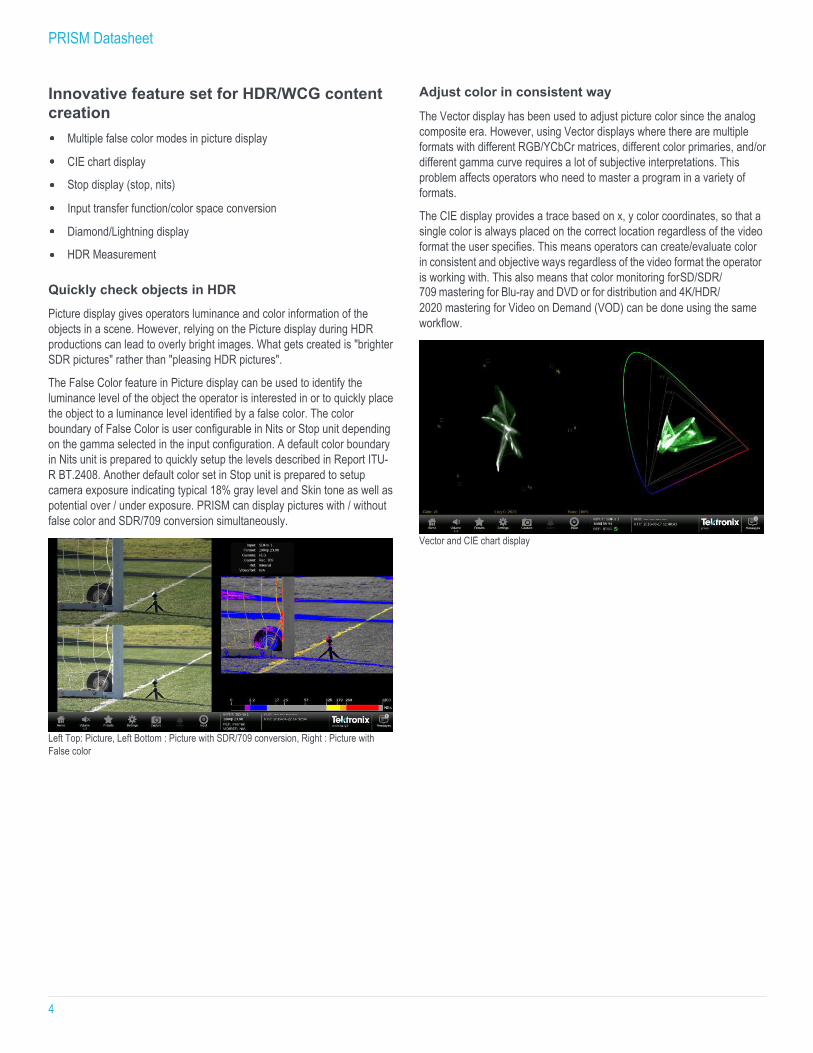
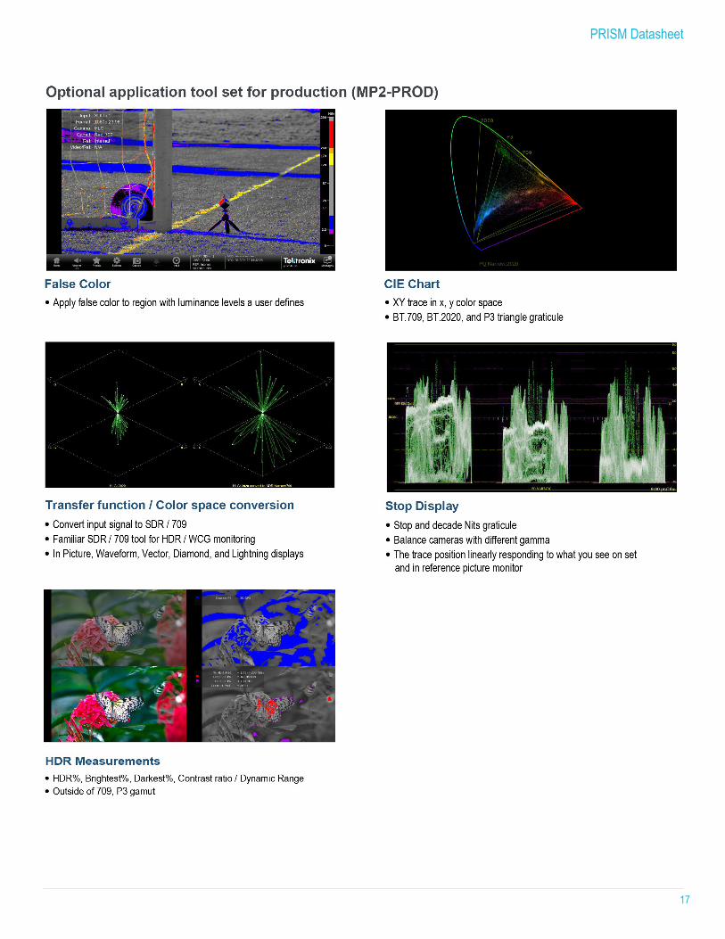
The False Color feature in Picture display can be used to identify the luminance level of the object the operator is interested in or to quickly place the object to a luminance level identified by a false color. The color boundary of False Color is user configurable in Nits or Stop unit depending on the gamma selected in the input configuration. A default color boundary in Nits unit is prepared to quickly setup the levels described in Report ITU- R BT.2408. Another default color set in Stop unit is prepared to setup camera exposure indicating typical 18% gray level and Skin tone as well as potential over / under exposure. PRISM can display pictures with / without false color and SDR/709 conversion simultaneously.
Left Top: Picture, Left Bottom : Picture with SDR/709 conversion, Right : Picture with False color
Adjust color in consistent way
The Vector display has been used to adjust picture color since the analog composite era. However, using Vector displays where there are multiple formats with different RGB/YCbCr matrices, different color primaries, and/or different gamma curve requires a lot of subjective interpretations. This problem affects operators who need to master a program in a variety of formats.
The CIE display provides a trace based on x, y color coordinates, so that a single color is always placed on the correct location regardless of the video format the user specifies. This means operators can create/evaluate color in consistent and objective ways regardless of the video format the operator is working with. This also means that color monitoring for SD/SDR/ 709 mastering for Blu-ray and DVD or for distribution and 4K/HDR/ 2020 mastering for Video on Demand (VOD) can be done using the same workflow.
Vector and CIE chart display
PRISM Datasheet
5
Simplify camera setup in complex HDR productions
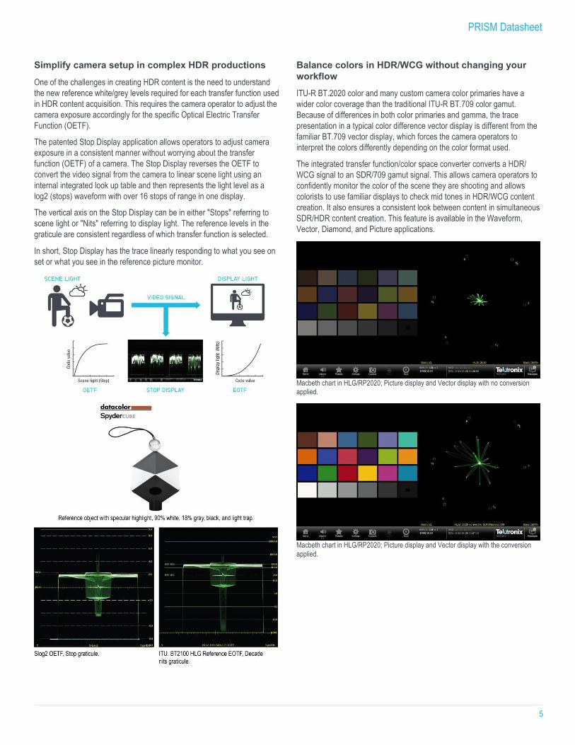
One of the challenges in creating HDR content is the need to understand the new reference white/grey levels required for each transfer function used in HDR content acquisition. This requires the camera operator to adjust the camera exposure accordingly for the specific Optical Electric Transfer Function (OETF).
The patented Stop Display application allows operators to adjust camera exposure in a consistent manner without worrying about the transfer function (OETF) of a camera. The Stop Display reverses the OETF to convert the video signal from the camera to linear scene light using an internal integrated look up table and then represents the light level as a log2 (stops) waveform with over 16 stops of range in one display.
The vertical axis on the Stop Display can be in either "Stops" referring to scene light or "Nits" referring to display light. The reference levels in the graticule are consistent regardless of which transfer function is selected.
In short, Stop Display has the trace linearly responding to what you see on set or what you see in the reference picture monitor.
Balance colors in HDR/WCG without changing your workflow ITU-R BT.2020 color and many custom camera color primaries have a wider color coverage than the traditional ITU-R BT.709 color gamut. Because of differences in both color primaries and gamma, the trace presentation in a typical color difference vector display is different from the familiar BT.709 vector display, which forces the camera operators to interpret the colors differently depending on the color format used.
The integrated transfer function/color space converter converts a HDR/ WCG signal to an SDR/709 gamut signal. This allows camera operators to confidently monitor the color of the scene they are shooting and allows colorists to use familiar displays to check mid tones in HDR/WCG content creation. It also ensures a consistent look between content in simultaneous SDR/HDR content creation. This feature is available in the Waveform, Vector, Diamond, and Picture applications.
Macbeth chart in HLG/RP2020; Picture display and Vector display with no conversion applied.
Macbeth chart in HLG/RP2020; Picture display and Vector display with the conversion applied.
PRISM Datasheet
6
Analyze the scene to create a compelling story
HDR/WCG technology gives editors more flexibility in story telling, but pushing the technology to the specification limit can ruin the end viewers' experience. PRISM offers objective picture measurements helping editors to confidently create convincing content to please viewers.
HDR measurements show the percent area that exceeds 100% diffuse white, so that users can manage the specular highlights. Brightest and Darkest percentages area offer the practical maximum/minimum luminance level and are used in calculation of contrast ratio to identify the dynamic range of the scene. Since the parameters are user configurable, the users may set the percentage screen area to match the ITU-R BT. 2408-1 experiments. Outside 709/P3 color detection will indicate the picture regions with the color outside of either ITU-R BT.709 or DCI-P3. It is useful to see the location where you might have a change in color at HDR/WCG to SDR/709 standard conversion and to ensure you are compliant with the standard set by the client.
Editors and QC operators can use the measurement result presented in the numerical read out objectively and/or in false coloring in the picture application subjectively.
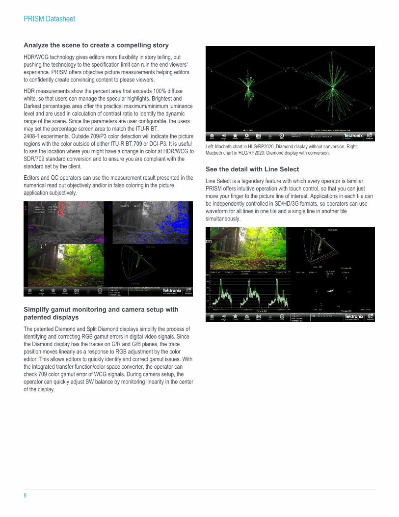
Simplify gamut monitoring and camera setup with patented displays The patented Diamond and Split Diamond displays simplify the process of identifying and correcting RGB gamut errors in digital video signals. Since the Diamond display has the traces on G/R and G/B planes, the trace position moves linearly as a response to RGB adjustment by the color editor. This allows editors to quickly identify and correct gamut issues. With the integrated transfer function/color space converter, the operator can check 709 color gamut error of WCG signals. During camera setup, the operator can quickly adjust BW balance by monitoring linearity in the center of the display.
Left: Macbeth chart in HLG/RP2020; Diamond display without conversion. Right: Macbeth chart in HLG/RP2020; Diamond display with conversion.
See the detail with Line Select Line Select is a legendary feature with which every operator is familiar. PRISM offers intuitive operation with touch control, so that you can just move your finger to the picture line of interest. Applications in each tile can be independently controlled in SD/HD/3G formats, so operators can use waveform for all lines in one tile and a single line in another tile simultaneously.
PRISM Datasheet
7
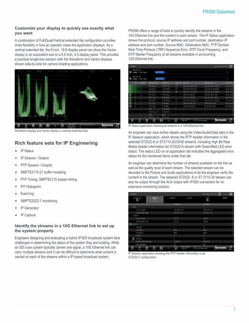
Customize your display to quickly see exactly what you want A combination of Full/Quad/Vertical extended tile configuration provides more flexibility in how an operator views the application displays. As a vertical extended tile, the 9 inch, 16:9 display panel can show the Vector display in an equivalent size to a 6.5 inch, 4:3 display panel. This provides a practical single-box solution with the Waveform and Vector displays shown side-by-side for camera shading applications.
Waveform display and Vector display in vertical extended tiles
Rich feature sets for IP Engineering IP Status
IP Session / Graphs
PTP Session / Graphs
SMPTE2110-21 buffer modeling
PTP Timing, SMPTE2110 stream timing
PIT Histogram
Event log
SMPTE2022-7 monitoring
IP Generator
IP Capture Identify the streams in a 10G Ethernet link to set up the system properly Engineers designing and evaluating a hybrid IP/SDI broadcast system face challenges in determining the status of the system they are building. While an SDI coax system typically carries one signal, a 10G Ethernet link can carry multiple streams and it can be difficult to determine what content is carried on each of the streams within a IP based broadcast system.
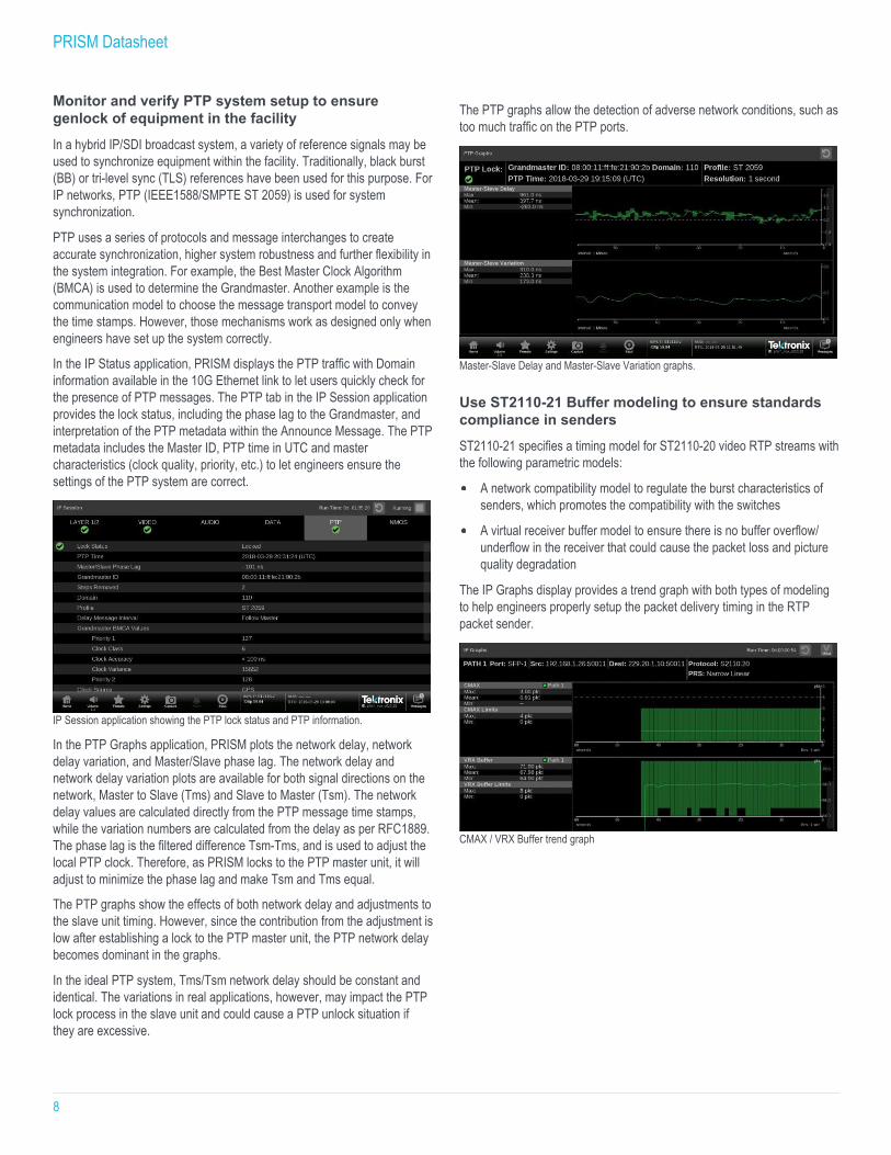
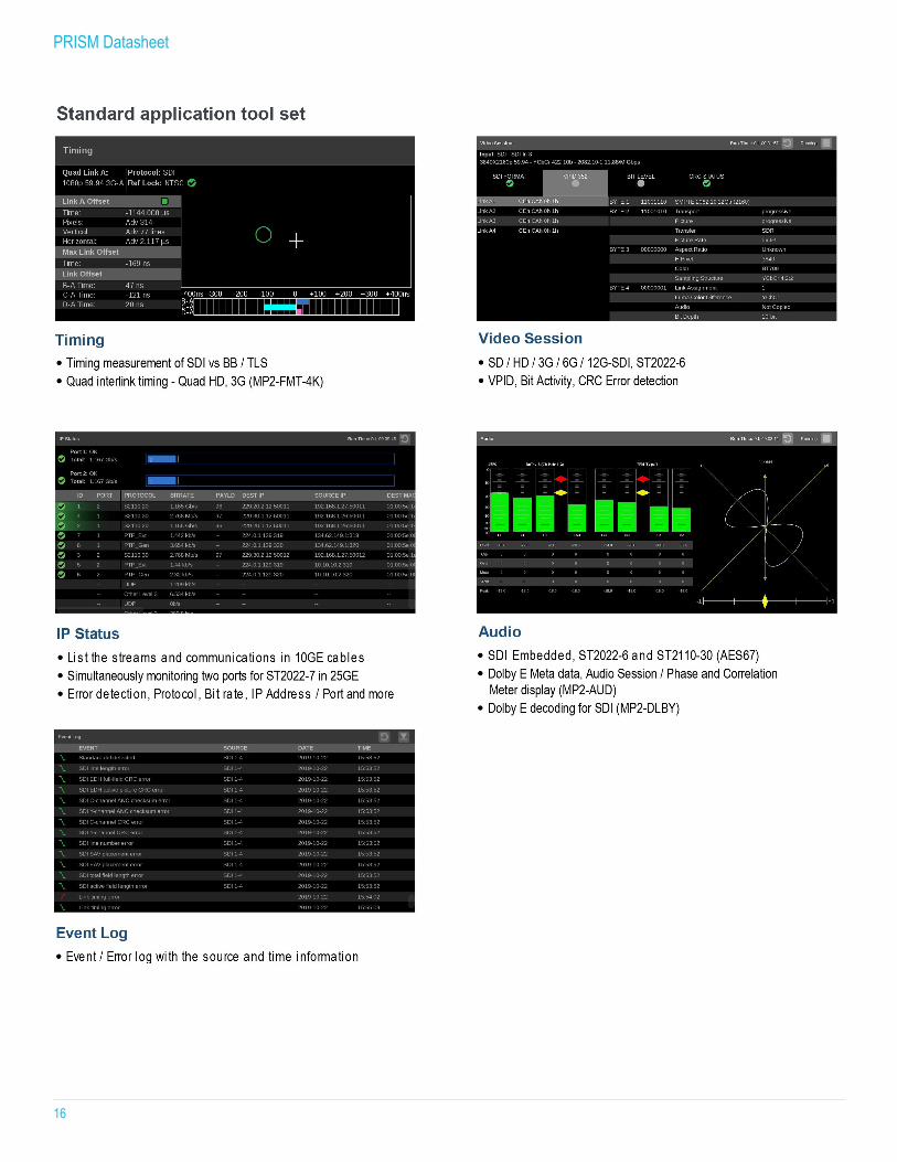
PRISM offers a range of tools to quickly identify the streams in the 10G Ethernet link and the content in each stream. The IP Status application shows the protocol, source IP address and port number, destination IP address and port number, Source MAC, Destination MAC, PTP Domain, Real Time Protocol (TRP) Sequence Error, RTP Clock Frequency, and RTP Marker Frequency of all streams available in an incoming 10G Ethernet link.
IP Status application showing all streams in a 10G Ethernet link.
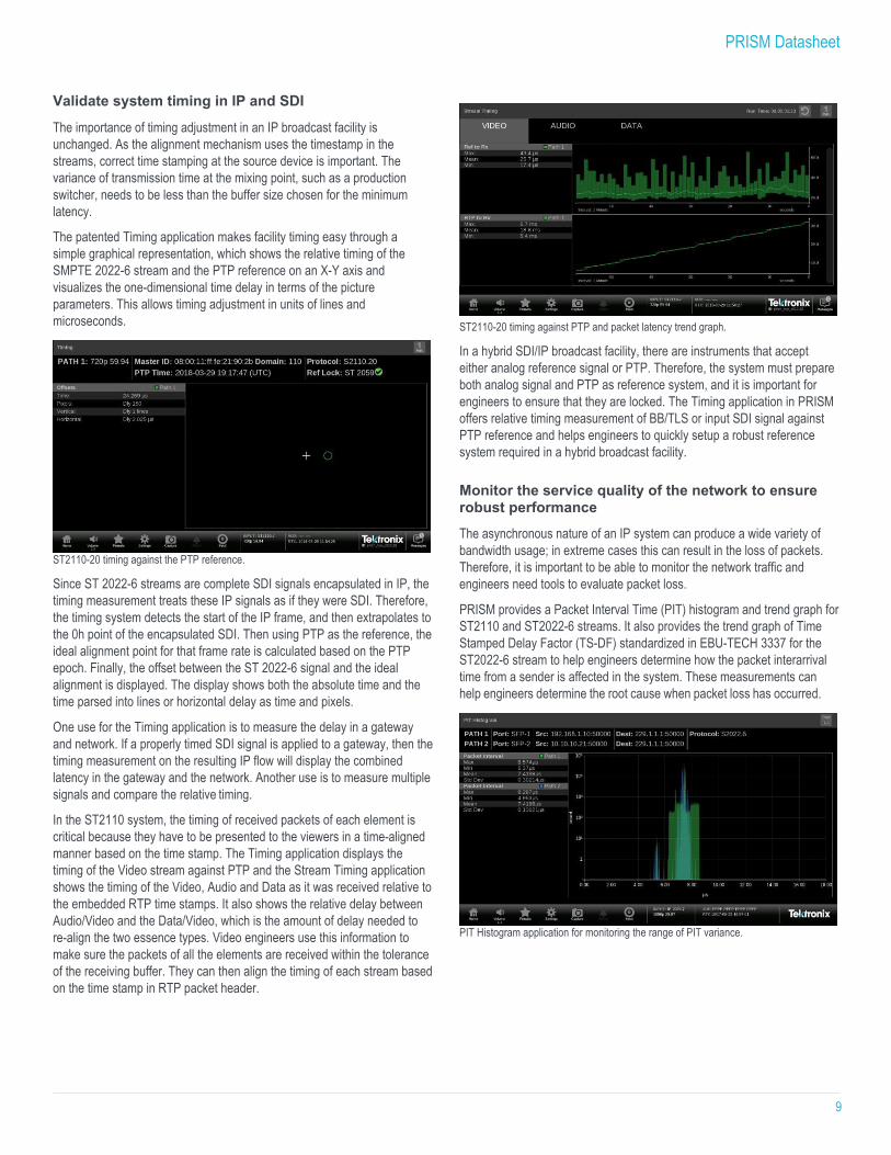
An engineer can view further details using the Video/Audio/Data tabs in the IP Session application, which shows the RTP header information in the selected ST2022-6 or ST2110-20/30/40 streams, including High Bit Rate Media header information for ST2022-6 stream with Green/Red LED error status. The status LED on an application tab indicates the aggregated error status for the monitored items under that tab.
An engineer can determine the number of streams available on the link as well as the quality level of each stream. The selected stream can be decoded to the Picture and Audio applications to let the engineer verify the content in the stream. The selected ST2022- 6 or ST 2110-20 stream can also be output through the AUX output with IP/SDI conversion for an extensive monitoring solution.
IP Session application showing the RTP header information in an ST2022-7 configuration.
PRISM Datasheet
8
Monitor and verify PTP system setup to ensure genlock of equipment in the facility In a hybrid IP/SDI broadcast system, a variety of reference signals may be used to synchronize equipment within the facility. Traditionally, black burst (BB) or tri-level sync (TLS) references have been used for this purpose. For IP networks, PTP (IEEE1588/SMPTE ST 2059) is used for system synchronization.
PTP uses a series of protocols and message interchanges to create accurate synchronization, higher system robustness and further flexibility in the system integration. For example, the Best Master Clock Algorithm (BMCA) is used to determine the Grandmaster. Another example is the communication model to choose the message transport model to convey the time stamps. However, those mechanisms work as designed only when engineers have set up the system correctly.
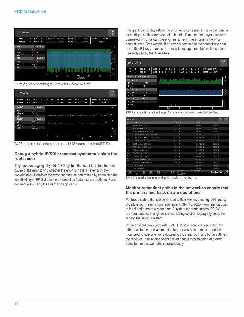
In the IP Status application, PRISM displays the PTP traffic with Domain information available in the 10G Ethernet link to let users quickly check for the presence of PTP messages. The PTP tab in the IP Session application provides the lock status, including the phase lag to the Grandmaster, and interpretation of the PTP metadata within the Announce Message. The PTP metadata includes the Master ID, PTP time in UTC and master characteristics (clock quality, priority, etc.) to let engineers ensure the settings of the PTP system are correct.
IP Session application showing the PTP lock status and PTP information.
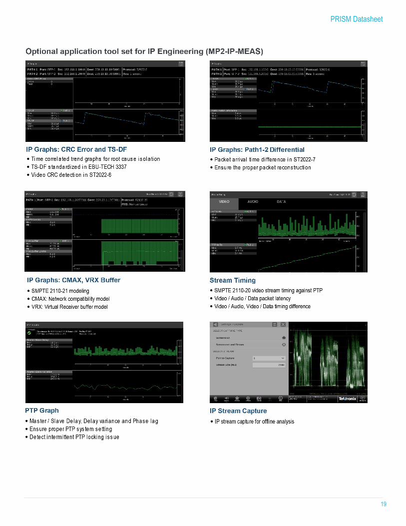
In the PTP Graphs application, PRISM plots the network delay, network delay variation, and Master/Slave phase lag. The network delay and network delay variation plots are available for both signal directions on the network, Master to Slave (Tms) and Slave to Master (Tsm). The network delay values are calculated directly from the PTP message time stamps, while the variation numbers are calculated from the delay as per RFC1889. The phase lag is the filtered difference Tsm-Tms, and is used to adjust the local PTP clock. Therefore, as PRISM locks to the PTP master unit, it will adjust to minimize the phase lag and make Tsm and Tms equal.
The PTP graphs show the effects of both network delay and adjustments to the slave unit timing. However, since the contribution from the adjustment is low after establishing a lock to the PTP master unit, the PTP network delay becomes dominant in the graphs.
In the ideal PTP system, Tms/Tsm network delay should be constant and identical. The variations in real applications, however, may impact the PTP lock process in the slave unit and could cause a PTP unlock situation if they are excessive.
The PTP graphs allow the detection of adverse network conditions, such as too much traffic on the PTP ports.
Master-Slave Delay and Master-Slave Variation graphs. Use ST2110-21 Buffer modeling to ensure standards compliance in senders ST2110-21 specifies a timing model for ST2110-20 video RTP streams with the following parametric models:
A network compatibility model to regulate the burst characteristics of senders, which promotes the compatibility with the switches
A virtual receiver buffer model to ensure there is no buffer overflow/ underflow in the receiver that could cause the packet loss and picture quality degradation
The IP Graphs display provides a trend graph with both types of modeling to help engineers properly setup the packet delivery timing in the RTP packet sender.
CMAX / VRX Buffer trend graph
PRISM Datasheet
9
Validate system timing in IP and SDI
The importance of timing adjustment in an IP broadcast facility is unchanged. As the alignment mechanism uses the timestamp in the streams, correct time stamping at the source device is important. The variance of transmission time at the mixing point, such as a production switcher, needs to be less than the buffer size chosen for the minimum latency.
The patented Timing application makes facility timing easy through a simple graphical representation, which shows the relative timing of the SMPTE 2022-6 stream and the PTP reference on an X-Y axis and visualizes the one-dimensional time delay in terms of the picture parameters. This allows timing adjustment in units of lines and microseconds.
ST2110-20 timing against the PTP reference.
Since ST 2022-6 streams are complete SDI signals encapsulated in IP, the timing measurement treats these IP signals as if they were SDI. Therefore, the timing system detects the start of the IP frame, and then extrapolates to the 0h point of the encapsulated SDI. Then using PTP as the reference, the ideal alignment point for that frame rate is calculated based on the PTP epoch. Finally, the offset between the ST 2022-6 signal and the ideal alignment is displayed. The display shows both the absolute time and the time parsed into lines or horizontal delay as time and pixels.
One use for the Timing application is to measure the delay in a gateway and network. If a properly timed SDI signal is applied to a gateway, then the timing measurement on the resulting IP flow will display the combined latency in the gateway and the network. Another use is to measure multiple signals and compare the relative timing.
In the ST2110 system, the timing of received packets of each element is critical because they have to be presented to the viewers in a time-aligned manner based on the time stamp. The Timing application displays the timing of the Video stream against PTP and the Stream Timing application shows the timing of the Video, Audio and Data as it was received relative to the embedded RTP time stamps. It also shows the relative delay between Audio/Video and the Data/Video, which is the amount of delay needed to re-align the two essence types. Video engineers use this information to make sure the packets of all the elements are received within the tolerance of the receiving buffer. They can then align the timing of each stream based on the time stamp in RTP packet header.
ST2110-20 timing against PTP and packet latency trend graph.
In a hybrid SDI/IP broadcast facility, there are instruments that accept either analog reference signal or PTP. Therefore, the system must prepare both analog signal and PTP as reference system, and it is important for engineers to ensure that they are locked. The Timing application in PRISM offers relative timing measurement of BB/TLS or input SDI signal against PTP reference and helps engineers to quickly setup a robust reference system required in a hybrid broadcast facility.
Monitor the service quality of the network to ensure robust performance The asynchronous nature of an IP system can produce a wide variety of bandwidth usage; in extreme cases this can result in the loss of packets. Therefore, it is important to be able to monitor the network traffic and engineers need tools to evaluate packet loss.
PRISM provides a Packet Interval Time (PIT) histogram and trend graph for ST2110 and ST2022-6 streams. It also provides the trend graph of Time Stamped Delay Factor (TS-DF) standardized in EBU-TECH 3337 for the ST2022-6 stream to help engineers determine how the packet interarrival time from a sender is affected in the system. These measurements can help engineers determine the root cause when packet loss has occurred.
PIT Histogram application for monitoring the range of PIT variance.
PRISM Datasheet
10
PIT trend graph for monitoring the trend of PIT variance over time.
TS-DF trend graph for monitoring the trend of TS-DF variance over time (ST2022-6). Debug a hybrid IP/SDI broadcast system to isolate the root cause Engineers debugging a hybrid IP/SDI system first need to isolate the root cause of the error to find whether the error is in the IP layer or in the content layer. Details of the error can then be determined by examining the identified layer. PRISM offers error detection feature sets in both the IP and content layers using the Event Log application.
The graphical displays show the error trend correlated to historical data. In these displays, the errors detected in both IP and content layers are time correlated, which allows the engineer to verify the error is in the IP or content layer. For example, if an error is detected in the content layer but not in the IP layer, then the error may have happened before the content was wrapped by the IP headers.
RTP Sequence Error incident graph for monitoring the errors detected over time.
Event Log application for checking the details of error events.
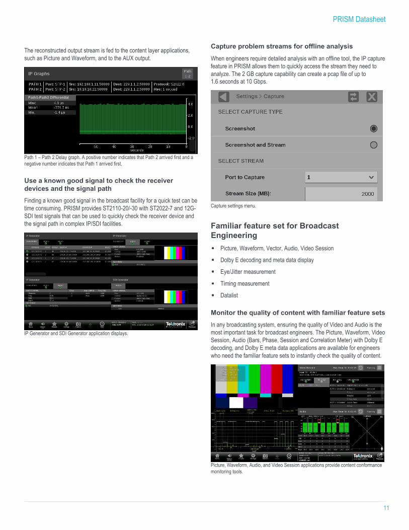
Monitor redundant paths in the network to ensure that the primary and back up are operational For broadcasters that are committed to their clients, ensuring 24/7 quality broadcasting is a minimum requirement. SMPTE 2022-7 was standardized to build and operate a redundant IP system for broadcasters. PRISM provides broadcast engineers a monitoring solution to properly setup the redundant ST2110 system.
When an input configured with SMPTE 2022-7 enabled is selected, the difference in the receive time of datagrams on path number 1 and 2 is monitored to help engineers determine the signal path and buffer setting in the receiver. PRISM also offers packet header interpretation and error detection for the two paths simultaneously.
PRISM Datasheet
11
The reconstructed output stream is fed to the content layer applications, such as Picture and Waveform, and to the AUX output.
Path 1 – Path 2 Delay graph. A positive number indicates that Path 2 arrived first and a negative number indicates that Path 1 arrived first.
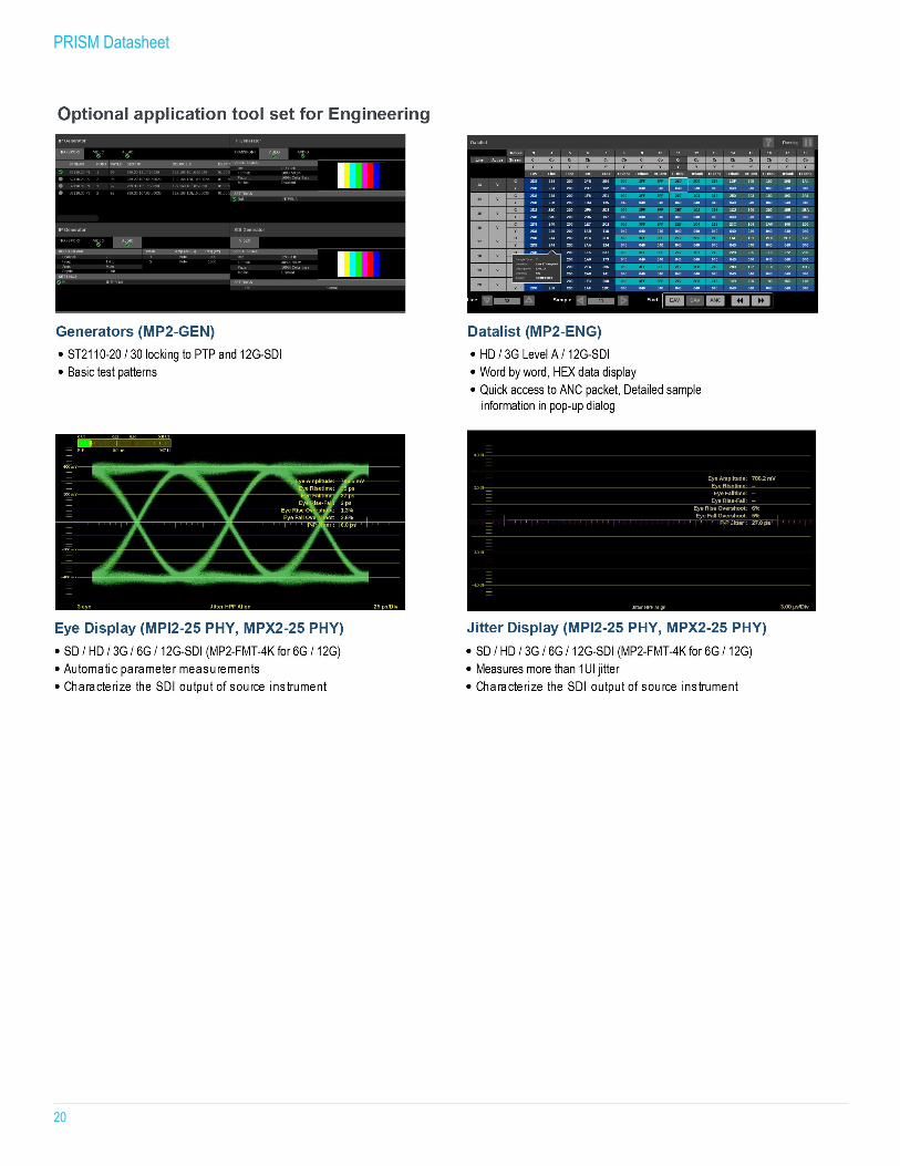
Use a known good signal to check the receiver devices and the signal path Finding a known good signal in the broadcast facility for a quick test can be time consuming. PRISM provides ST2110-20/-30 with ST2022-7 and 12G- SDI test signals that can be used to quickly check the receiver device and the signal path in complex IP/SDI facilities.
IP Generator and SDI Generator application displays.
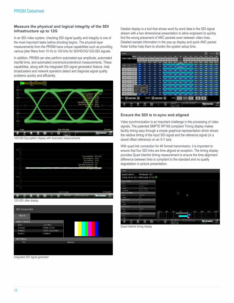
Capture problem streams for offline analysis
When engineers require detailed analysis with an offline tool, the IP capture feature in PRISM allows them to quickly access the stream they need to analyze. The 2 GB capture capability can create a pcap file of up to 1.6 seconds at 10 Gbps.
Capture settings menu.
Familiar feature set for Broadcast Engineering
Picture, Waveform, Vector, Audio, Video Session
Dolby E decoding and meta data display
Eye/Jitter measurement
Timing measurement
Datalist
Monitor the quality of content with familiar feature sets In any broadcasting system, ensuring the quality of Video and Audio is the most important task for broadcast engineers. The Picture, Waveform, Video Session, Audio (Bars, Phase, Session and Correlation Meter) with Dolby E decoding, and Dolby E meta data applications are available for engineers who need the familiar feature sets to instantly check the quality of content.
Picture, Waveform, Audio, and Video Session applications provide content conformance monitoring tools.
PRISM Datasheet
12
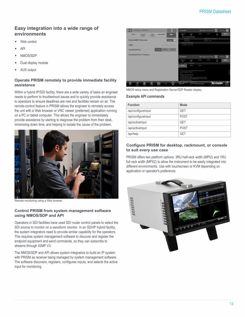
Measure the physical and logical integrity of the SDI infrastructure up to 12G In an SDI video system, checking SDI signal quality and integrity is one of the most important tasks before shooting begins. The physical layer measurements from the PRISM have unique capabilities such as providing various jitter filters from 10 Hz to 100 kHz for SD/HD/3G/12G-SDI signals.
In addition, PRISM can also perform automated eye amplitude, automated rise/fall time, and automated overshoot/undershoot measurements. These capabilities, along with the integrated SDI signal generation feature, help broadcasters and network operators detect and diagnose signal quality problems quickly and efficiently.
12G-SDI Eye pattern display with Automatic measurements
12G-SDI Jitter display
Integrated SDI signal generator
Datalist display is a tool that shows word by word data in the SDI signal stream with a two dimensional presentation to allow engineers to quickly find the wrong placement of ANC packets even between video lines. Detailed sample information in the pop-up display and quick ANC packet finder further help them to shorten the system setup time.
Ensure the SDI is in-sync and aligned Video synchronization is an important challenge in the processing of video signals. The patented SMPTE RP168 compliant Timing display makes facility timing easy through a simple graphical representation which shows the relative timing of the input SDI signal and the reference signal (or a saved offset reference) on an X-Y axis.
With quad link connection for 4K format transmission, it is important to ensure that four SDI links are time aligned at reception. The timing display provides Quad interlink timing measurement to ensure the time alignment difference between links is compliant to the standard and no quality degradation in picture presentation.
Quad interlink timing display
PRISM Datasheet
13
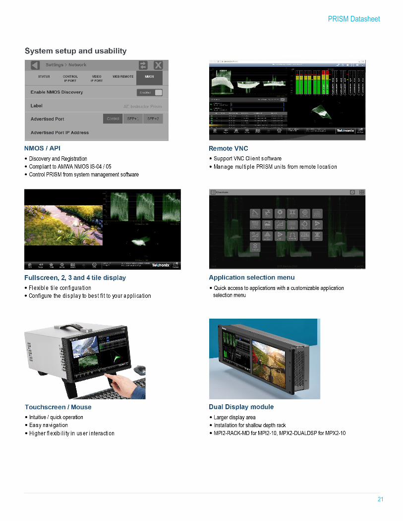
Easy integration into a wide range of environments
Web control
API
NMOS/SDP
Dual display module
AUX output
Operate PRISM remotely to provide immediate facility assistance Within a hybrid IP/SDI facility, there are a wide variety of tasks an engineer needs to perform to troubleshoot issues and to quickly provide assistance to operators to ensure deadlines are met and facilities remain on air. The remote-control feature in PRISM allows the engineer to remotely access the unit with a Web browser or VNC viewer (preferred) application running on a PC or tablet computer. This allows the engineer to immediately provide assistance by starting to diagnose the problem from their desk, minimizing down time, and helping to isolate the cause of the problem.
Remote monitoring using a Web browser. Control PRISM from system management software using NMOS/SDP and API Operators in SDI facilities have used SDI router control panels to select the SDI source to monitor on a waveform monitor. In an SDI/IP hybrid facility, the system integrators need to provide similar capability for the operators. This requires system management software to discover and register the endpoint equipment and send commands, so they can subscribe to streams through IGMP V3.
The NMOS/SDP and API allows system integrators to build an IP system with PRISM as receiver being managed by system management software. The software discovers, registers, configures inputs, and selects the active input for monitoring.
NMOS setup menu and Registration Server/SDP Reader display.
Example API commands
Function Mode /api/configureInput GET /api/configureInput POST /api/activeInput GET /api/activeInput POST /api/help GET
Configure PRISM for desktop, rackmount, or console to suit every use case PRISM offers two platform options: 3RU half-rack width (MPI2) and 1RU full rack width (MPX2) to allow the instrument to be easily integrated into different environments. Use with touchscreen or KVM depending on application or operator's preference.
PRISM Datasheet
14
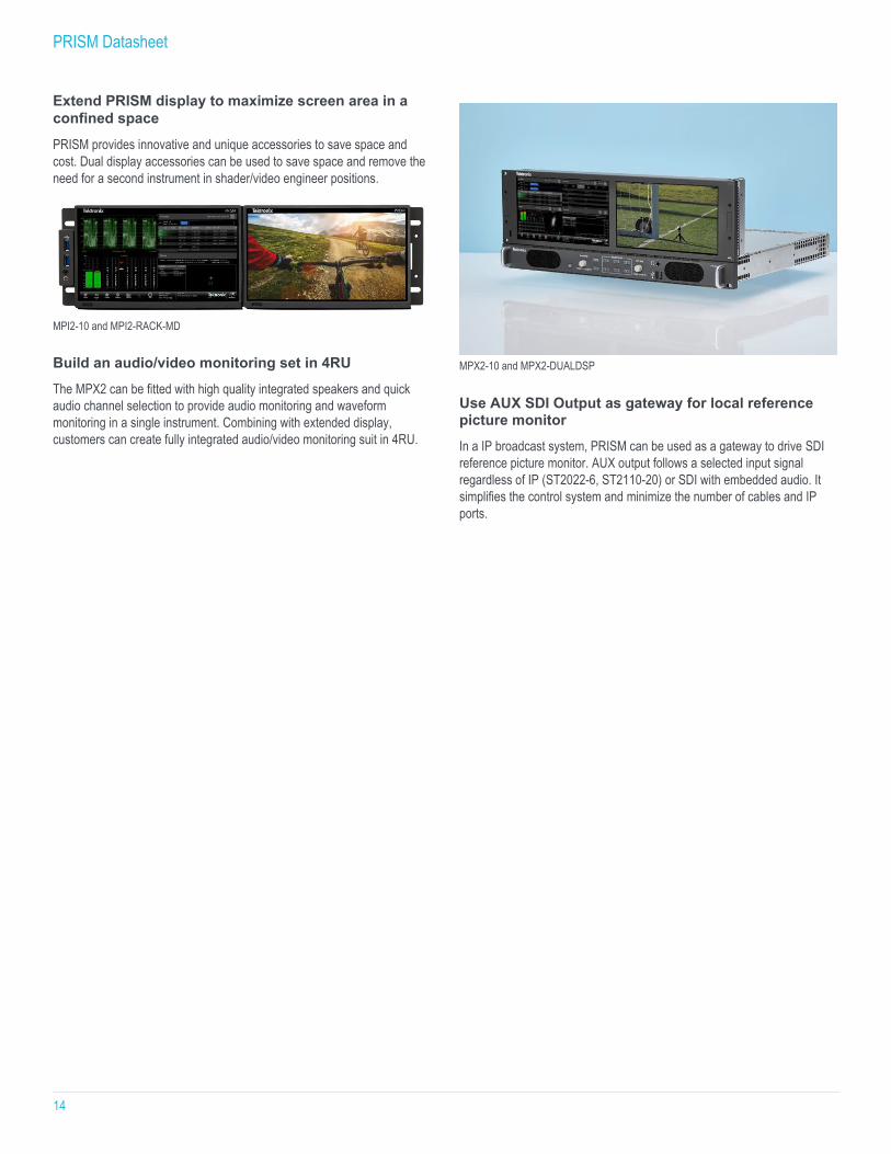
Extend PRISM display to maximize screen area in a confined space PRISM provides innovative and unique accessories to save space and cost. Dual display accessories can be used to save space and remove the need for a second instrument in shader/video engineer positions.
MPI2-10 and MPI2-RACK-MD Build an audio/video monitoring set in 4RU The MPX2 can be fitted with high quality integrated speakers and quick audio channel selection to provide audio monitoring and waveform monitoring in a single instrument. Combining with extended display, customers can create fully integrated audio/video monitoring suit in 4RU.
MPX2-10 and MPX2-DUALDSP
Use AUX SDI Output as gateway for local reference picture monitor In a IP broadcast system, PRISM can be used as a gateway to drive SDI reference picture monitor. AUX output follows a selected input signal regardless of IP (ST2022-6, ST2110-20) or SDI with embedded audio. It simplifies the control system and minimize the number of cables and IP ports.

PRISM Datasheet
15
PRISM Datasheet
16
PRISM Datasheet
17

PRISM Datasheet
18
PRISM Datasheet
19
PRISM Datasheet
20
PRISM Datasheet
21
PRISM Datasheet
22
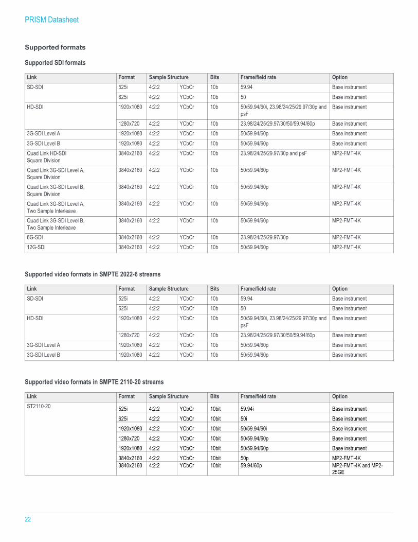
Supported formats
Supported SDI formats
Link Format Sample Structure Bits Frame/field rate Option SD-SDI 525i 4:2:2 YCbCr 10b 59.94 Base instrument
625i 4:2:2 YCbCr 10b 50 Base instrument HD-SDI 1920x1080 4:2:2 YCbCr 10b 50/59.94/60i, 23.98/24/25/29.97/30p and
psF Base instrument
1280x720 4:2:2 YCbCr 10b 23.98/24/25/29.97/30/50/59.94/60p Base instrument 3G-SDI Level A 1920x1080 4:2:2 YCbCr 10b 50/59.94/60p Base instrument 3G-SDI Level B 1920x1080 4:2:2 YCbCr 10b 50/59.94/60p Base instrument Quad Link HD-SDI Square Division
3840x2160 4:2:2 YCbCr 10b 23.98/24/25/29.97/30p and psF MP2-FMT-4K
Quad Link 3G-SDI Level A, Square Division
3840x2160 4:2:2 YCbCr 10b 50/59.94/60p MP2-FMT-4K
Quad Link 3G-SDI Level B, Square Division
3840x2160 4:2:2 YCbCr 10b 50/59.94/60p MP2-FMT-4K
Quad Link 3G-SDI Level A, Two Sample Interleave
3840x2160 4:2:2 YCbCr 10b 50/59.94/60p MP2-FMT-4K
Quad Link 3G-SDI Level B, Two Sample Interleave
3840x2160 4:2:2 YCbCr 10b 50/59.94/60p MP2-FMT-4K
6G-SDI 3840x2160 4:2:2 YCbCr 10b 23.98/24/25/29.97/30p MP2-FMT-4K 12G-SDI 3840x2160 4:2:2 YCbCr 10b 50/59.94/60p MP2-FMT-4K
Supported video formats in SMPTE 2022-6 streams
Link Format Sample Structure Bits Frame/field rate Option SD-SDI 525i 4:2:2 YCbCr 10b 59.94 Base instrument
625i 4:2:2 YCbCr 10b 50 Base instrument HD-SDI 1920x1080 4:2:2 YCbCr 10b 50/59.94/60i, 23.98/24/25/29.97/30p and
psF Base instrument
1280x720 4:2:2 YCbCr 10b 23.98/24/25/29.97/30/50/59.94/60p Base instrument 3G-SDI Level A 1920x1080 4:2:2 YCbCr 10b 50/59.94/60p Base instrument 3G-SDI Level B 1920x1080 4:2:2 YCbCr 10b 50/59.94/60p Base instrument
Supported video formats in SMPTE 2110-20 streams
Link Format Sample Structure Bits Frame/field rate Option ST2110-20 525i 4:2:2 YCbCr 10bit 59.94i Base instrument
625i 4:2:2 YCbCr 10bit 50i Base instrument 1920x1080 4:2:2 YCbCr 10bit 50/59.94/60i Base instrument 1280x720 4:2:2 YCbCr 10bit 50/59.94/60p Base instrument 1920x1080 4:2:2 YCbCr 10bit 50/59.94/60p Base instrument
3840x2160 4:2:2 YCbCr 10bit 50p MP2-FMT-4K
3840x2160 4:2:2 YCbCr 10bit 59.94/60p MP2-FMT-4K and MP2-25GE
PRISM Datasheet
23
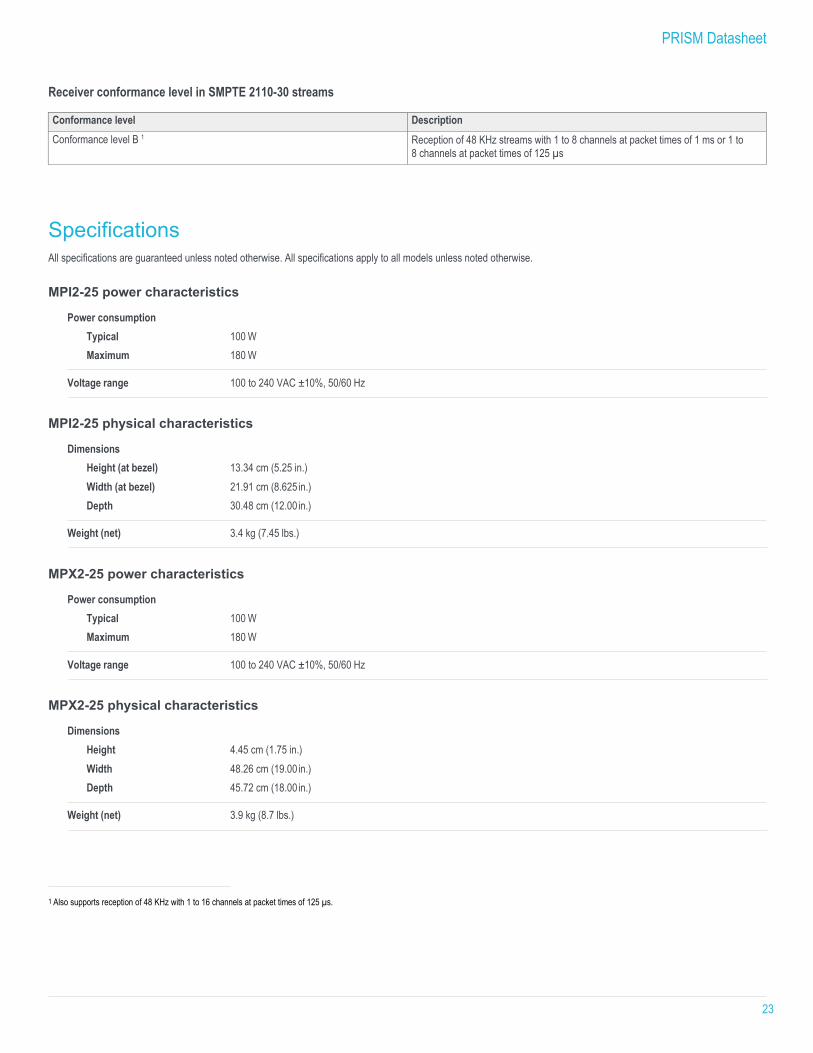
Receiver conformance level in SMPTE 2110-30 streams
Conformance level Description Conformance level B 1 Reception of 48 KHz streams with 1 to 8 channels at packet times of 1 ms or 1 to
8 channels at packet times of 125 µs
Specifications All specifications are guaranteed unless noted otherwise. All specifications apply to all models unless noted otherwise.
MPI2-25 power characteristics
Power consumption Typical 100 W Maximum 180 W
Voltage range 100 to 240 VAC ±10%, 50/60 Hz
MPI2-25 physical characteristics
Dimensions Height (at bezel) 13.34 cm (5.25 in.) Width (at bezel) 21.91 cm (8.625 in.) Depth 30.48 cm (12.00 in.)
Weight (net) 3.4 kg (7.45 lbs.)
MPX2-25 power characteristics
Power consumption Typical 100 W Maximum 180 W
Voltage range 100 to 240 VAC ±10%, 50/60 Hz
MPX2-25 physical characteristics
Dimensions Height 4.45 cm (1.75 in.) Width 48.26 cm (19.00 in.) Depth 45.72 cm (18.00 in.)
Weight (net) 3.9 kg (8.7 lbs.)
1 Also supports reception of 48 KHz with 1 to 16 channels at packet times of 125 µs.

PRISM Datasheet
24
AUX SDI output characteristics (Generator mode)
Output level 800 mV ±10% into 75 Ω load
PRISM Datasheet
25
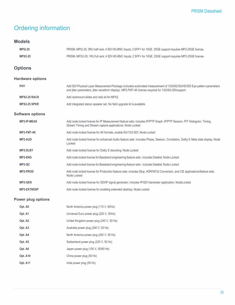
Ordering information Models
MPI2-25 PRISM, MPI2-25; 3RU half rack; 4 SDI HD-BNC Inputs; 2 SFP+ for 10GE. 25GE support requires MP2-25GE license.
MPX2-25 PRISM, MPX2-25; 1RU full rack; 4 SDI HD-BNC Inputs; 2 SFP+ for 10GE. 25GE support requires MP2-25GE license.
Options Hardware options
PHY Add SDI Physical Layer Measurement Package (includes automated measurement of 12G/6G/3G/HD/SDI Eye pattern parameters and jitter parameters; jitter waveform display). MP2-FMT-4K license required for 12G/6G-SDI support
MPX2-25 RACK Add rackmount slides and rails kit for MPX2
MPX2-25 SPKR Add integrated stereo speaker set, No field upgrade kit is available Software options
MP2-IP-MEAS Add node locked license for IP Measurement feature sets: includes IP/PTP Graph, IP/PTP Session, PIT Histogram, Timing, Stream Timing and Stream capture applications; Node Locked
MP2-FMT-4K Add node locked license for 4K formats, enable 6G/12G-SDI; Node Locked
MP2-AUD Add node locked license for enhanced Audio feature sets: includes Phase, Session, Correlation, Dolby E Meta data display; Node Locked
MP2-DLBY Add node locked license for Dolby E decoding; Node Locked
MP2-ENG Add node locked license for Baseband engineering feature sets : includes Datalist; Node Locked
MP2-QC Add node locked license for Baseband engineering feature sets : includes Datalist; Node Locked
MP2-PROD Add node locked license for Production feature sets: includes Stop, HDR/WCG Conversion, and CIE applications/feature sets; Node Locked
MP2-GEN Add node locked license for SDI/IP signal generator; includes IP/SDI Generator application; Node Locked
MP2-EXTNDSP Add node locked license for enabling extended desktop; Node Locked Power plug options
Opt. A0 North America power plug (115 V, 60 Hz)
Opt. A1 Universal Euro power plug (220 V, 50 Hz)
Opt. A2 United Kingdom power plug (240 V, 50 Hz)
Opt. A3 Australia power plug (240 V, 50 Hz)
Opt. A4 North America power plug (240 V, 50 Hz)
Opt. A5 Switzerland power plug (220 V, 50 Hz)
Opt. A6 Japan power plug (100 V, 50/60 Hz)
Opt. A10 China power plug (50 Hz)
Opt. A11 India power plug (50 Hz)
PRISM Datasheet
26
Opt. A12 Brazil power plug (60 Hz)
Opt. A99 No power cord Service options
Opt. C3 Calibration Service 3 Years
Opt. C5 Calibration Service 5 Years
Opt. D1 Calibration Data Report
Opt. D3 Calibration Data Report 3 Years (with Opt. C3)
Opt. D5 Calibration Data Report 5 Years (with Opt. C5)
Opt. G3 Complete Care 3 Years (includes loaner, scheduled calibration, and more)
Opt. G5 Complete Care 5 Years (includes loaner, scheduled calibration, and more)
Opt. R3 Repair Service 3 Years (including warranty)
Opt. R5 Repair Service 5 Years (including warranty) Post purchase upgrades
MPI2-25-UP Opt. PHY Add SDI Physical Layer Measurement Package (incl. automated measurement of 12G/6G/3G/HD/SDI Eye pattern parameters and
jitter parameters; jitter waveform display). MP2-FMT-4K license required for 12G/6G-SDI support
MPX2-25-UP Opt. PHY Add SDI Physical Layer Measurement Package (incl. automated measurement of 12G/6G/3G/HD/SDI Eye pattern parameters and
jitter parameters; jitter waveform display). MP2-FMT-4K license required for 12G/6G-SDI support Warranty Standard product warranty: 1 year; Long-term product support: 5 years

PRISM Datasheet
27
Recommended accessories
MPI2-PTBL Portable cabinet with handle, feet, Tile bail and protective front cover
MPI-RACK-MM 19 inch, 3RU dual rack cabinet for one MPI unit or two MPI units in a side-by-side installation, includes front panel USB/headphone connectors for each MPI unit
MPI-RACK-MW 19 inch, 3RU dual rack cabinet for one MPI unit or one MPI unit in a side-by-side installation with a WFM52x0, WFM7200, WFM8x00 instrument, includes front panel USB/headphone connectors for one MPI unit
MPI2-RACK-MD 19 inch, 3RU Rack Cabinet with display and touch panel, USB/Headphone connector on rack ear
MPX2-DUALDSP 19 inch, 3RU Dual display unit with touch panel, USB/Headphone connector on rack ear
MP-SFP Opt. 3GTO1 SD/HD/3G Optical (1310 nm) SDI SFP transmitter module (to be installed into SDI SFP+ cage for optical SDI loop through output) Opt. 3GTD1 SD/HD/3G DIN SDI SFP transmitter module (to be installed into SDI SFP+ cage for SDI loop through output with DIN coaxial
connector) Opt. 3GTH1 SD/HD/3G HDBNC SDI SFP transmitter module (to be installed into SDI SFP+ cage for SDI loop through output with HDBNC
coaxial connector) Opt. 10GESR 10G Ethernet short range (850 nm) transceiver module Opt. 10GELR 10G Ethernet long range (1310 nm) transceiver module Opt. 25GESR 25G Ethernet short range (850 nm) transceiver module Opt. 25GELR 25G Ethernet long range (1310 nm) transceiver module
MP-CBL
Opt. DUALDSP PRISM A cable kit for MPX2-DUALDSP, Two sets of 2 M DisplayPort male to DisplayPort male cable and 2 M USB 3.0 A male to B male cable
Opt. HDBNC-BNC PRISM Coaxial adapter cables from high-density male BNC connector to standard female BNC connector (a set of 3 cables, 75 Ω, 0.5 M long)
1 Not supported by MPI2-25, MPX2-25, or an MPI, MPX, MPI2-10, or MPX2-10 instrument with a 25GE Upgrade kit installed.
PRISM Datasheet
28
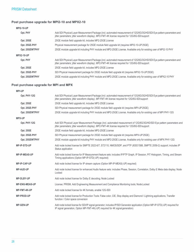
Post purchase upgrade for MPI2-10 and MPX2-10
MPI2-10-UP Opt. PHY Add SDI Physical Layer Measurement Package (incl. automated measurement of 12G/6G/3G/HD/SDI Eye pattern parameters and
jitter parameters; jitter waveform display). MP2-FMT-4K license required for 12G/6G-SDI support Opt. 25GE 25GE module field upgrade kit, includes MP2-25GE License Opt. 25GE-PHY Physical measurement package for 25GE module field upgrade kit (requires MPI2-10-UP 25GE) Opt. 25GEWTPHY 25GE module upgrade kit including PHY module and MP2-25GE License. Available only for existing user of MPI2-10 PHY
MPX2-10-UP
Opt. PHY Add SDI Physical Layer Measurement Package (incl. automated measurement of 12G/6G/3G/HD/SDI Eye pattern parameters and jitter parameters; jitter waveform display). MP2-FMT-4K license required for 12G/6G-SDI support
Opt. 25GE 25GE module field upgrade kit, includes MP2-25GE License Opt. 25GE-PHY SDI Physical measurement package for 25GE module field upgrade kit (requires MPX2-10-UP 25GE) Opt. 25GEWTPHY 25GE module upgrade kit including PHY module and MP2-25GE License. Available only for existing user of MPX2-10 PHY
Post purchase upgrade for MPI and MPX
MPI-UP Opt. PHY-12G Add SDI Physical Layer Measurement Package (incl. automated measurement of 12G/6G/3G/HD/SDI Eye pattern parameters and
jitter parameters; jitter waveform display). MP-FMT-4K license required for 12G/6G-SDI support Opt. 25GE 25GE module field upgrade kit, includes MP2-25GE License Opt. 25GE-PHY SDI Physical measurement package for 25GE module field upgrade kit (requires MPI-UP 25GE) Opt. 25GEWTPHY 25GE module upgrade kit including PHY module and MP2-25GE License. Available only for existing user of MPI PHY-12G
MPX-UP
Opt. PHY-12G Add SDI Physical Layer Measurement Package (incl. automated measurement of 12G/6G/3G/HD/SDI Eye pattern parameters and jitter parameters; jitter waveform display). MP2-FMT-4K license required for 12G/6G-SDI support
Opt. 25GE 25GE module field upgrade kit, includes MP2-25GE License Opt. 25GE-PHY SDI Physical measurement package for 25GE module field upgrade kit (requires MPX-UP 25GE) Opt. 25GEWTPHY 25GE module upgrade kit including PHY module and MP2-25GE License. Available only for existing user of MPX PHY-12G
MP-IP-STD-UP Add node locked license for SMPTE 2022-6/7, ST2110, NMOS/SDP, and PTP (IEEE1588, SMPTE 2059-2) support; includes IP
Status application
MP-IP-MEAS-UP Add node locked license for IP Measurement feature sets: includes IP/PTP Graph, IP Session, PIT Histogram, Timing, and Stream Timing applications (Option MP-IP-STD(-UP) required)
MP-IP-CAP-UP Add node locked license for IP stream capture (Option MP-IP-MEAS(-UP) required)
MP-AUD-UP Add node locked license for enhanced Audio feature sets: includes Phase, Session, Correlation, Dolby E Meta data display; Node
Locked
MP-DLBY-UP Add node locked license for Dolby E decoding; Node Locked
MP-ENG-MEAS-UP License; PRISM, Add Engineering Measurement and Compliance Monitoring tools; Node Locked
MP-FMT-4K-UP Add node locked license for 4K formats, enable 12G-SDI
MP-PROD-UP Add node locked license for Production Tools: False color, CIE, Stop display and Diamond / Lightning applications, Transfer function / Color space conversion
MP-GEN-UP Add node locked license for SDI/IP signal generator; includes IP/SDI Generator application (Option MP-IP-STD(-UP) required for IP signal generation, Option MP-FMT-4K(-UP) required for 4K signal generation)
PRISM Datasheet
29
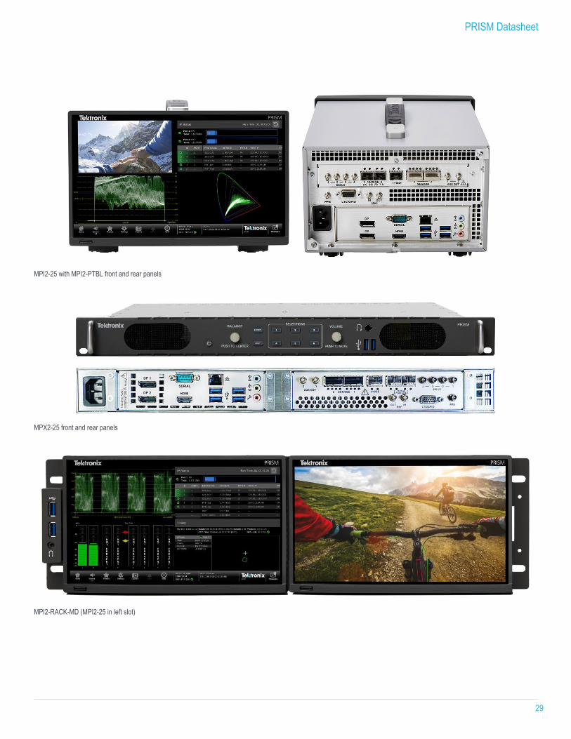
MPI2-25 with MPI2-PTBL front and rear panels
MPX2-25 front and rear panels
MPI2-RACK-MD (MPI2-25 in left slot)
PRISM Datasheet
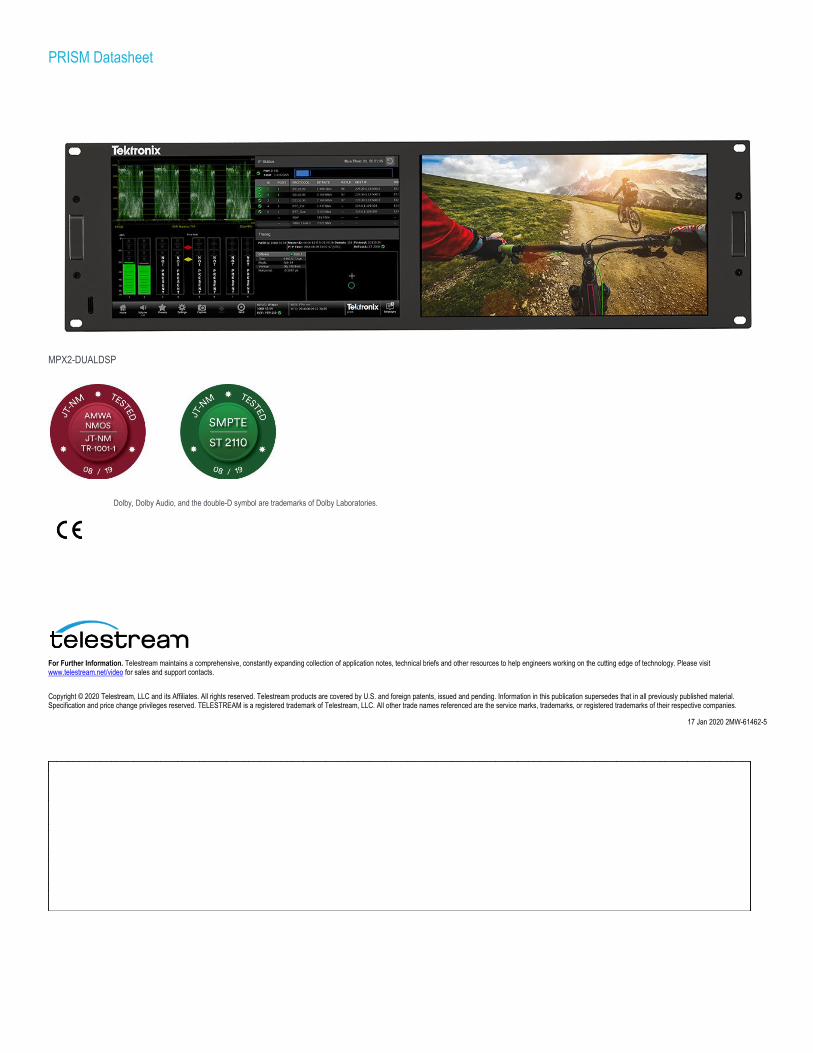
MPX2-DUALDSP
Dolby, Dolby Audio, and the double-D symbol are trademarks of Dolby Laboratories.
For Further Information. Telestream maintains a comprehensive, constantly expanding collection of application notes, technical briefs and other resources to help engineers working on the cutting edge of technology. Please visit www.telestream.net/video for sales and support contacts.
Copyright © 2020 Telestream, LLC and its Affiliates. All rights reserved. Telestream products are covered by U.S. and foreign patents, issued and pending. Information in this publication supersedes that in all previously published material. Specification and price change privileges reserved. TELESTREAM is a registered trademark of Telestream, LLC. All other trade names referenced are the service marks, trademarks, or registered trademarks of their respective companies.
17 Jan 2020 2MW-61462-5