compress 3000 - εχνικο... · pdf filesplit heat pump,...
TRANSCRIPT

Technical GuideIssue 2013/04
Air to water heat pump, split version
Compress 3000
6 720 648 132-00.2I
EHP 8-16 AWS E-S | ODU 7,5-12 | HMAWS E-S
6 72
0 80
7 11
5 20
13/0
4 D
E

2 | Table of contents
BASIS DOCUMENT - DO NOT PRINT
Table of contents
1 Air to water heat pumps, split version, from Bosch . . . . . . . . 31.1 Compress 3000 . . . . . . . . . . . . . . . . . . . . . . . . . . . . . . . . 31.2 Arguments in favour of a Bosch split-version air to water
heat pump . . . . . . . . . . . . . . . . . . . . . . . . . . . . . . . . . . . . 3
2 Basic principles . . . . . . . . . . . . . . . . . . . . . . . . . . . . . . . . . . . . . . . 42.1 How heat pumps work . . . . . . . . . . . . . . . . . . . . . . . . . . . 42.2 Efficiency, coefficient of performance and seasonal
performance factor . . . . . . . . . . . . . . . . . . . . . . . . . . . . . 5
3 Technical description . . . . . . . . . . . . . . . . . . . . . . . . . . . . . . . . . . 83.1 Compress 3000 . . . . . . . . . . . . . . . . . . . . . . . . . . . . . . . . 83.2 ODU outdoor unit . . . . . . . . . . . . . . . . . . . . . . . . . . . . . . 133.3 HMAWS .. E/S indoor unit . . . . . . . . . . . . . . . . . . . . . . . 17
4 Planning and design of the heat pump system . . . . . . . . . . . . 224.1 Planning steps (overview) . . . . . . . . . . . . . . . . . . . . . . . 224.2 Determining the building heat load (heat demand) . . . 234.3 Heat pump design . . . . . . . . . . . . . . . . . . . . . . . . . . . . . . 254.4 Design for cooling mode (only HMAWS .. E) . . . . . . . . . 294.5 Installing the Compress 3000 . . . . . . . . . . . . . . . . . . . . 324.6 Design and installation location of other system
components . . . . . . . . . . . . . . . . . . . . . . . . . . . . . . . . . . 414.7 Refrigerant circuit . . . . . . . . . . . . . . . . . . . . . . . . . . . . . . 444.8 Heating water circuit . . . . . . . . . . . . . . . . . . . . . . . . . . . 454.9 Electrical connection . . . . . . . . . . . . . . . . . . . . . . . . . . . 464.10 Regulations and standards . . . . . . . . . . . . . . . . . . . . . . . 534.11 German Energy Savings Order (EnEV) . . . . . . . . . . . . . 544.12 German Renewable Energies Act (EEWärmeG) . . . . . . 57
5 System examples . . . . . . . . . . . . . . . . . . . . . . . . . . . . . . . . . . . . 585.1 Information regarding all system examples . . . . . . . . . 585.2 System example 1: single-energy operating mode with
split heat pump, separate DHW cylinder and buffer cylinder . . . . . . . . . . . . . . . . . . . . . . . . . . . . . . . . . . . . . . 59
5.3 System example 2: single-energy operating mode with split heat pump, buffer cylinder and the use of solar energy for DHW heating . . . . . . . . . . . . . . . . . . . . . . . . . . . . . . . 61
5.4 System example 3: single-energy operating mode with split heat pump, buffer cylinder and the use of solar energy for central heating and DHW heating . . . . . . . . . . . . . . 63
5.5 System example 4: single-energy operating mode with split heat pump, buffer cylinder and the use of biomass energy for central heating and DHW heating . . . . . . . . 65
5.6 System example 5: single-energy operating mode with split heat pump, separate DHW cylinder and buffer cylinder with cooling and the use of solar energy for DHW
. . . . . . . . . . . . . . . . . . . . . . . . . . . . . . . . . . . . . . . . . . . . 675.7 System example 6: single-energy operating mode with
split heat pump, separate DHW cylinder and buffer cylinder with partial cooling . . . . . . . . . . . . . . . . . . . . . 69
5.8 System example 7: dual-energy operating mode with split heat pump, second heat appliance, separate DHW cylinder and buffer cylinder . . . . . . . . . . . . . . . . . . . . . . . . . . . . 71
5.9 System example 8: dual-energy operating mode with split heat pump, second heat appliance, buffer cylinder and the use of solar energy for DHW heating . . . . . . . . . . . . . . 73
5.10 System example 9: dual-energy operating mode with split heat pump, second heat appliance, buffer cylinder and the use of biomass energy for central heating and DHW heating . . . . . . . . . . . . . . . . . . . . . . . . . . . . . . . . . . . . . . 75
6 Control . . . . . . . . . . . . . . . . . . . . . . . . . . . . . . . . . . . . . . . . . . . . . 776.1 Heating controls . . . . . . . . . . . . . . . . . . . . . . . . . . . . . . . 776.2 Controlling the DHW heating . . . . . . . . . . . . . . . . . . . . . 796.3 External inputs on the heat pump control . . . . . . . . . . . 79
7 DHW heating and heat storage . . . . . . . . . . . . . . . . . . . . . . . . . 807.1 HR 200/300 DHW cylinders for heat pumps . . . . . . . . 807.2 SH290 RW and SH370 RW DHW cylinders . . . . . . . . . 847.3 SMH400 E and SMH500 E dual-energy cylinders . . . . 887.4 P120 W and P200 W buffer cylinders . . . . . . . . . . . . . 907.5 P50 W buffer cylinder . . . . . . . . . . . . . . . . . . . . . . . . . . 93
8 Accessories . . . . . . . . . . . . . . . . . . . . . . . . . . . . . . . . . . . . . . . . . 95
Compress 30006 720 807 115 2013/04
BASIS DOCUMENT - DO NOT PRINT

Air to water heat pumps, split version, from Bosch | 3
BASIS DOCUMENT - DO NOT PRINT
1 Air to water heat pumps, split version, from Bosch
1.1 Compress 3000The Compress 3000 consists of an outdoor unit (ODU 7.5, 10 or 12t) and an indoor unit (HMAWS 8 E/S or 16 E/S).HMAWS 8 – 16 S: dual-energy application with a second heat appliance, e.g. oil or gas boiler as a booster heater.HMAWS 8 – 16 E: single-energy application with an electrical heating insert (integrated in the indoor unit) as a booster heater.
1.2 Arguments in favour of a Bosch split-version air to water heat pump
Comment: Written for Germany, must be adapted to local market.
Germany is one of the world's leading nations for climate protection. The commitments made in the Kyoto protocol have been honoured, but this is no reason to rest on our laurels, because we are still a long way off meeting the medium-term climate targets. Making the right choice when choosing a central heating system can make a considerable contribution towards achieving these targets. Industry studies anticipate that the heat pump will benefit from this choice in the long term. Thanks to the ever-increasing efficiency of the appliances, it is in new building projects that the split-version air to water heat pump will really make its mark. The outdoor and indoor units are connected using electrical cables and two refrigerant pipes, enabling a range of flexible installation options. The single-energy variant – HMAWS E with an integrated electrical heating insert (9 kW) – provides an independent supply for heating and domestic hot water. The split-version air to water heat pump, with its intelligent integrated control and inverter technology, is a truly efficient heat appliance.A dual-energy system solution is a possibility if an existing boiler is to be used to manage peak loads but the heat load has been reduced by modernisation measures. The HMAWS S can then generate the bulk of the heating energy. The dual-energy operating mode of the HMAWS S combined with a wall mounted gas condensing boiler can cover an output range of up to 25 kW.If necessary, the integrated control can send a request to the existing boiler control.
Reassuringly reliable• Bosch split-version air to water heat pumps fulfil the
Bosch quality requirements regarding high performance and service life.
• The appliances are checked and tested in the factory.• A 24-hour hotline deals with all questions.• The security of a major brand: spare parts and
servicing available, even in 15 years' time.
Highly ecological• Around 75 % of the heat energy involved in operating
the heat pump is renewable; if “green electricity” is used (wind, water or solar energy), it can be up to 100 % renewable.
• No emissions during operation• Very positive EnEV (German Energy Savings Order)
assessment
Comment: EnEv only applicable in Germany
Extremely economical• Low-maintenance, durable technology with closed
circuits• No (financial) expense required for drilling, in contrast
to brine to water and water to water heat pumps
Simple and problem-free• No approval required from environmental authorities• No special requirements regarding the size of the
property
6 720 807 115 2013/04Compress 3000
BASIS DOCUMENT - DO NOT PRINT
4 | Basic principles
BASIS DOCUMENT - DO NOT PRINT
2 Basic principles
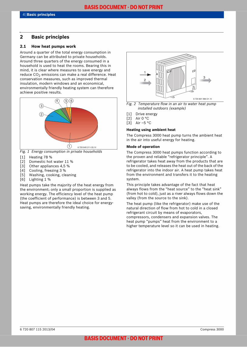
2.1 How heat pumps workAround a quarter of the total energy consumption in Germany can be attributed to private households. Around three quarters of the energy consumed in a household is used to heat the rooms. Bearing this in mind, it is clear where measures to save energy and reduce CO2 emissions can make a real difference. Heat conservation measures, such as improved thermal insulation, modern windows and an economical, environmentally friendly heating system can therefore achieve positive results.
Fig. 1 Energy consumption in private households[1] Heating 78 %[2] Domestic hot water 11 %[3] Other appliances 4,5 %[4] Cooling, freezing 3 %[5] Washing, cooking, cleaning[6] Lighting 1 %Heat pumps take the majority of the heat energy from the environment; only a small proportion is supplied as working energy. The efficiency level of the heat pump (the coefficient of performance) is between 3 and 5. Heat pumps are therefore the ideal choice for energy-saving, environmentally friendly heating.
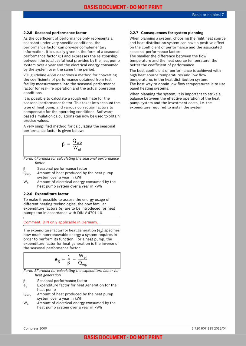
Fig. 2 Temperature flow in an air to water heat pump installed outdoors (example)
[1] Drive energy[2] Air 0 °C[3] Air –5 °C
Heating using ambient heatThe Compress 3000 heat pump turns the ambient heat in the air into useful energy for heating.
Mode of operationThe Compress 3000 heat pumps function according to the proven and reliable “refrigerator principle”. A refrigerator takes heat away from the products that are to be cooled, and releases the heat out of the back of the refrigerator into the indoor air. A heat pump takes heat from the environment and transfers it to the heating system. This principle takes advantage of the fact that heat always flows from the “heat source” to the “heat sink” (from hot to cold), just as a river always flows down the valley (from the source to the sink).The heat pump (like the refrigerator) make use of the natural direction of flow from hot to cold in a closed refrigerant circuit by means of evaporators, compressors, condensers and expansion valves. The heat pump “pumps” heat from the environment to a higher temperature level so it can be used in heating.
1
2
3
4 5 6
6 720 645 211-33.1il
6 720 801 984-01.1il
1
23
Compress 30006 720 807 115 2013/04
BASIS DOCUMENT - DO NOT PRINT

Basic principles | 5
BASIS DOCUMENT - DO NOT PRINT
Fig. 3 Schematic diagram of the refrigerant circuit in the Compress 3000 heat pump (with refrigerant R410A)
[1] Evaporator[2] Compressor[3] Condenser[4] Expansion valveThe evaporator (1) contains a working fluid with a very low boiling point (known as a refrigerant). The refrigerant is at a lower temperature than the heat source (e.g. ground, water, air) and a low pressure level. The heat therefore flows from the heat source to the refrigerant. The temperature of the refrigerant rises beyond its boiling point, causing it to evaporate before it is taken in by the compressor.The compressor (2) compresses the evaporated (gaseous) refrigerant to increase its pressure, which causes it to heat up even more. The drive energy from the compressor is also converted into heat which is transferred to the refrigerant. The temperature of the refrigerant continues to increase until it is higher than the temperature required by the heating system for the purposes of heating. Once the refrigerant reaches a certain temperature and pressure, it is conveyed to the condenser.In the condenser (3), the hot, gaseous refrigerant transfers the heat taken from the environment (heat source) and from the drive energy of the compressor to the cooler heating system (heat sink). Its temperature then decreases below the condensation point, causing it to turn back into a liquid. The refrigerant, which is now a liquid again but still highly pressurised, flows to the expansion valve.The expansion valve (4) ensures that the refrigerant is depressurised back to its initial pressure before it returns to the evaporator to take heat from the environment once again.
2.2 Efficiency, coefficient of performance and seasonal performance factor
2.2.1 EfficiencyEfficiency () describes the ratio between the available output and the energy input. Under ideal circumstances, the efficiency is 1. Technical processes always involve some losses, hence the efficiency of technical equipment is always below 1 ( < 1).
Form. 1 Formula for calculating efficiency Efficiency Pab Generated outputPel Supplied electrical inputHeat pumps draw a large proportion of the energy [they deliver] from the environment. This portion of energy is not described as supplied energy, as it is free of charge. If the efficiency were calculated under these conditions, it would be > 1. As this would not be correct, the coefficient of performance (COP) was introduced for heat pumps in order to describe the ratio of useful energy to that which has been expended (in this case, purely the working energy).
2.2.2 Coefficient of performanceThe coefficient of performance (COP, ) is a measured or calculated parameter for heat pumps under specified operating conditions, similar to the standardised fuel consumption for vehicles. The coefficient of performance ε describes the ratio between the available heating energy and the power drawn by the compressor.The coefficient of performance that can be achieved by a heat pump depends on the temperature differential between the heat source and the heat sink.The following rule of thumb for calculating the coefficient of performance () based on the temperature differential applies to modern appliances:
Form. 2 Formula for calculating the COP based on temperature
T Absolute temperature of the heat sink in KT0 Absolute temperature of the heat source in KThe following formula calculates the COP based on the ratio of output to electrical power consumption:
Form. 3Formula for calculating the COP based on electrical power consumption
Pel Electrical power consumption in kWQN Generated output in kW
6 720 801 985-01.1il
1
4
3
2
PabPel----------=
0,5 TT T0–------------------- 0,5
T T0+
T-------------------------= =
COPQNPel----------= =
6 720 807 115 2013/04Compress 3000
BASIS DOCUMENT - DO NOT PRINT

6 | Basic principles
BASIS DOCUMENT - DO NOT PRINT
2.2.3 Example COP calculation based on temperature differential
The following example calculates the COP of a heat pump for an underfloor heating system with a flow temperature of 35 °C and a radiator heating system at 50 °C when the heat source temperature is 0 °C.
Underfloor heating system (1)• T = 35 °C = (273 + 35) K = 308 K• T0 = 0 °C = (273 + 0) K = 273 K• T = T – T0 = (308 – 273) K = 35 KCalculation using formula 2:
Radiator heating system (2)• T = 50 °C = (273 + 50) K = 323 K• T0 = 0 °C = (273 + 0) K = 273 K• T = T – T0 = (323 – 273) K = 50 KCalculation using formula 2:
Fig. 4 Coefficients of performance based on example calculation
COP Coefficient of performance, T Temperature differential
2.2.4 Comparison of COPs for various heat pumps according to DIN EN 14511
For an approximate comparison of various heat pumps, DIN EN 14511 specifies conditions for determining the coefficient of performance, e.g. the type of heat source and the temperature of its heat transfer medium.
A AirB Brine W WaterAlong with the power consumption of the compressor, the coefficient of performance described in DIN EN 14511 also takes into account the drive power of auxiliary units, the proportional pump output of the brine pump or water pump or, in the case of air to water heat pumps, the proportional fan output. The difference between appliances with an integrated pump and those without an integrated pump also leads to significantly different coefficients of performance in practice. The only meaningful form of comparison is therefore a direct comparison between heat pumps of the same type.
The example shows that the COP for the underfloor heating system is 36 % higher than that of the radiator heating system.This gives us the following rule of thumb: 1 °C lower temperature deviation = 2,5 % higher COP.
0,5 TT--------- 0,5 308 K
35 K-------------------- 4,4= = =
0,5 TT--------- 0,5 323 K
50 K-------------------- 3,2= = =
00
1
2
3
4
5
6
7
8
9
10 20 30 40 50 60 70
1
2
1 ΔT = 35 K, ε = 4,42 ΔT = 50 K, ε = 3,2
ΔT (K)
COP
6 720 801 984-03.1il
BrineHeat1)/waterHeat2)
[ °C]
1) source and heat transfer medium temperature2) sink and appliance outlet temperature (heating flow)
Water1)/water2)
[ °C]
Air1)/water2) [ °C]
B0/W35 W10/W35 A7/W35B0/W45 W10/W45 A2/W35B5/W45 W15/W45 A–7/W35
Table 1 Comparison of heat pumps according to DIN EN 14511
The coefficients of performance (, COP) specified for Bosch heat pumps relate to the refrigerant circuit (without proportional pump output) and to the DIN EN 14511 calculation method for appliances with an integrated pump.
Compress 30006 720 807 115 2013/04
BASIS DOCUMENT - DO NOT PRINT
Basic principles | 7
BASIS DOCUMENT - DO NOT PRINT
2.2.5 Seasonal performance factorAs the coefficient of performance only represents a snapshot under very specific conditions, the performance factor can provide complementary information. It is usually given in the form of a seasonal performance factor () and expresses the relationship between the total useful heat provided by the heat pump system over a year and the electrical energy consumed by the system over the same time period. VDI guideline 4650 describes a method for converting the coefficients of performance obtained from test facility measurements into the seasonal performance factor for real-life operation and the actual operating conditions. It is possible to calculate a rough estimate for the seasonal performance factor. This takes into account the type of heat pump and various correction factors to compensate for the operating conditions. Software-based simulation calculations can now be used to obtain precise values.A very simplified method for calculating the seasonal performance factor is given below:
Form. 4Formula for calculating the seasonal performance factor
Seasonal performance factorQwp Amount of heat produced by the heat pump
system over a year in kWhWel Amount of electrical energy consumed by the
heat pump system over a year in kWh
2.2.6 Expenditure factorTo make it possible to assess the energy usage of different heating technologies, the now familiar expenditure factors (e) are to be introduced for heat pumps too in accordance with DIN V 4701-10.
Comment: DIN only applicable in Germany.
The expenditure factor for heat generation (eg) specifies how much non-renewable energy a system requires in order to perform its function. For a heat pump, the expenditure factor for heat generation is the inverse of the seasonal performance factor:
Form. 5Formula for calculating the expenditure factor for heat generation
Seasonal performance factoreg Expenditure factor for heat generation for the
heat pumpQwp Amount of heat produced by the heat pump
system over a year in kWhWel Amount of electrical energy consumed by the
heat pump system over a year in kWh
2.2.7 Consequences for system planningWhen planning a system, choosing the right heat source and heat distribution system can have a positive effect on the coefficient of performance and the associated seasonal performance factor: The smaller the difference between the flow temperature and the heat source temperature, the better the coefficient of performance. The best coefficient of performance is achieved with high heat source temperatures and low flow temperatures in the heat distribution system. The best way to obtain low flow temperatures is to use panel heating systems. When planning the system, it is important to strike a balance between the effective operation of the heat pump system and the investment costs, i.e. the expenditure required to install the system.
QwpWel--------------=
eg1----
WelQwp--------------= =
6 720 807 115 2013/04Compress 3000
BASIS DOCUMENT - DO NOT PRINT

8 | Technical description
BASIS DOCUMENT - DO NOT PRINT
3 Technical description
3.1 Compress 3000
3.1.1 System overview
Example: System example (single-energy operating mode)
Fig. 5 System example (single-energy operating mode) (list of abbreviations page 58)[1] HMAWS E
6 720 644 816-27.3I
1
Detailed information on other system examples, e.g. solutions involving parallel buffer cylinders and solar DHW heating can be found on page 59 ff.
Compress 30006 720 807 115 2013/04
BASIS DOCUMENT - DO NOT PRINT

Technical description | 9
BASIS DOCUMENT - DO NOT PRINT
Example: System example (dual-energy operating mode)
Fig. 6 System example (dual-energy operating mode) (list of abbreviations page 58)[1] HMAWS S
6 720 648 125-81.3I
1
6 720 807 115 2013/04Compress 3000
BASIS DOCUMENT - DO NOT PRINT
10 | Technical description
BASIS DOCUMENT - DO NOT PRINT
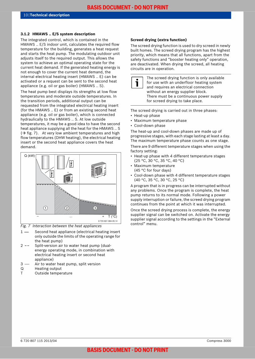
3.1.2 HMAWS .. E/S system descriptionThe integrated control, which is contained in the HMAWS .. E/S indoor unit, calculates the required flow temperature for the building, generates a heat request and starts the heat pump. The modulating outdoor unit adjusts itself to the required output. This allows the system to achieve an optimal operating state for the current heat demand. If the generated heating energy is not enough to cover the current heat demand, the internal electrical heating insert (HMAWS .. E) can be activated or a request can be sent to the second heat appliance (e.g. oil or gas boiler) (HMAWS .. S). The heat pump best displays its strengths at low flow temperatures and moderate outside temperatures. In the transition periods, additional output can be requested from the integrated electrical heating insert (for the HMAWS .. E) or from an existing second heat appliance (e.g. oil or gas boiler), which is connected hydraulically to the HMAWS .. S. At low outside temperatures, it may be a good idea to have the second heat appliance supplying all the heat for the HMAWS .. S ( fig. 7). At very low ambient temperatures and high flow temperatures (DHW heating), the electrical heating insert or the second heat appliance covers the heat demand.
Fig. 7 Interaction between the heat appliances1 Second heat appliance (electrical heating insert
only outside the limits of the operating range for the heat pump)
2 Split-version air to water heat pump (dual-energy operating mode, in combination with electrical heating insert or second heat appliance)
3 Air to water heat pump, split version Q Heating outputT Outside temperature
Screed drying (extra function)The screed drying function is used to dry screed in newly built homes. The screed drying program has the highest priority, which means that all functions, apart from the safety functions and “booster heating only” operation, are deactivated. When drying the screed, all heating circuits are in operation.
The screed drying is carried out in three phases:• Heat-up phase• Maximum temperature phase• Cool-down phaseThe heat-up and cool-down phases are made up of progressive stages, with each stage lasting at least a day. The maximum temperature phase counts as one stage. There are 9 different temperature stages when using the factory setting: • Heat-up phase with 4 different temperature stages
(25 °C, 30 °C, 35 °C, 40 °C)• Maximum temperature
(45 °C for four days)• Cool-down phase with 4 different temperature stages
(40 °C, 35 °C, 30 °C, 25 °C)A program that is in progress can be interrupted without any problems. Once the program is complete, the heat pump returns to its normal mode. Following a power supply interruption or failure, the screed drying program continues from the point at which it was interrupted.Once the screed drying process is complete, the energy supplier signal can be switched on. Activate the energy supplier signal according to the settings in the “External control” menu.
6 720 801 984-05.1il
T (°C)
Q (kW)
+
1 32
– ... +
The screed drying function is only available for use with an underfloor heating system and requires an electrical connection without an energy supplier block. There must be a continuous power supply for screed drying to take place.
Compress 30006 720 807 115 2013/04
BASIS DOCUMENT - DO NOT PRINT

Technical description | 11
BASIS DOCUMENT - DO NOT PRINT
3.1.3 Standard delivery
Fig. 8 Standard delivery for the ODU 7.5 outdoor unit[1] ODU 7.5
Fig. 9 Standard delivery for the ODU 10/11/12 outdoor unit[1] ODU 10/11/12
6 720 648 125-83.1I
1
6 720 648 125-84.1I
1
6 720 807 115 2013/04Compress 3000
BASIS DOCUMENT - DO NOT PRINT
12 | Technical description
BASIS DOCUMENT - DO NOT PRINT
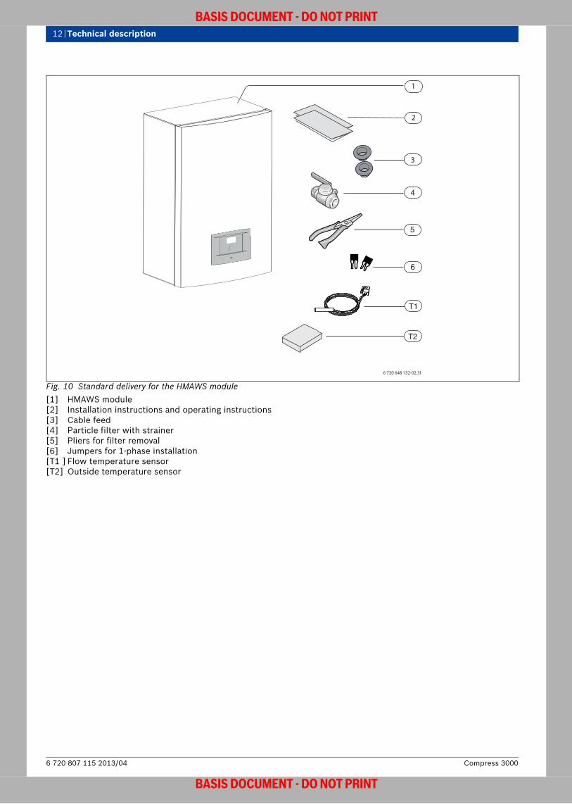
Fig. 10 Standard delivery for the HMAWS module[1] HMAWS module [2] Installation instructions and operating instructions[3] Cable feed[4] Particle filter with strainer[5] Pliers for filter removal[6] Jumpers for 1-phase installation[T1 ] Flow temperature sensor [T2] Outside temperature sensor
6 720 648 132-02.3I
2
4
T1
5
6
T2
3
Compress 30006 720 807 115 2013/04
BASIS DOCUMENT - DO NOT PRINT

Technical description | 13
BASIS DOCUMENT - DO NOT PRINT
3.2 ODU outdoor unit
3.2.1 Layout and function
Fig. 11 ODU outdoor unit (example figure ODU 10/11/12)The ODU outdoor unit extracts the heat from the air that is taken in. This heat energy is heated to a higher temperature level in a refrigerant circuit and then transferred to the heating water in the HMAWS module.The ODU 7.5 and 10 are electrically operated with 230 V; the ODU 11 and 12t with 400 V. The heat pump can either be supplied with household electricity or by means of a special heat pump electricity tariff. This gives users a great deal of freedom when choosing their electricity provider, allowing them to take advantage of the best offers nationwide. They are not necessarily bound to using regional providers.The outdoor unit comes pre-charged with a quantity of R410A refrigerant suitable for a refrigerant pipe length (one-way) of between 1 m and 30 m. The outdoor unit is connected to the indoor unit inside the house using a 3/8" and 5/8" refrigerant pipe.Benefits of this type of connection:• Simple connection to the existing 230 V AC or 400 V 3-
phase AC mains, without complex additional measures• Heat pump electricity tariffs can be used as an
alternative
6 720 801 984-07.1il
6 720 807 115 2013/04Compress 3000
BASIS DOCUMENT - DO NOT PRINT
14 | Technical description
BASIS DOCUMENT - DO NOT PRINT
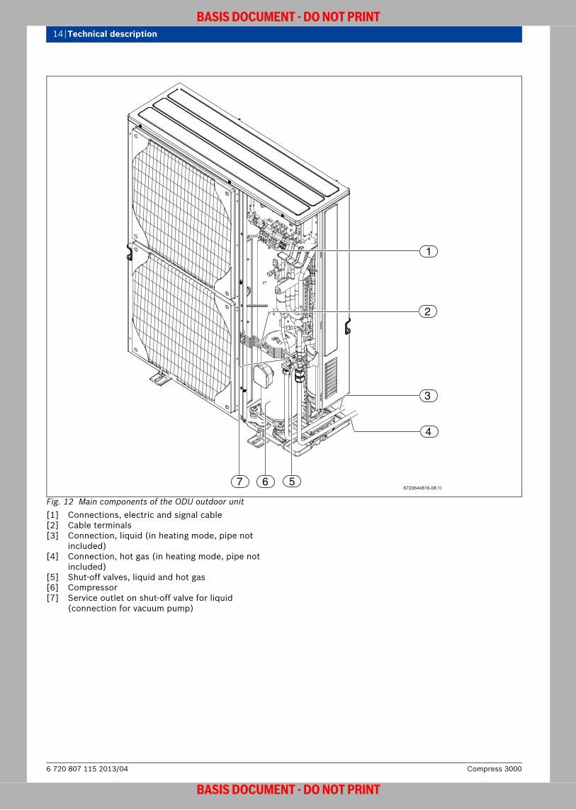
Fig. 12 Main components of the ODU outdoor unit[1] Connections, electric and signal cable[2] Cable terminals[3] Connection, liquid (in heating mode, pipe not
included)[4] Connection, hot gas (in heating mode, pipe not
included)[5] Shut-off valves, liquid and hot gas[6] Compressor[7] Service outlet on shut-off valve for liquid
(connection for vacuum pump)
1
2
3
4
566720644816-08.1I
7
Compress 30006 720 807 115 2013/04
BASIS DOCUMENT - DO NOT PRINT

Technical description | 15
BASIS DOCUMENT - DO NOT PRINT
3.2.2 Dimensions and specifications
Fig. 13 Dimensions of ODU 7.5 outdoor unit (measurements in mm)
Fig. 14 Dimensions of ODU 10, 11 and ODU 12 outdoor unit (measurements in mm)
950
330+309
43
175600
370
6 720 644 816-06.1I
1050
330+30
13
38
225600
370
6 720 644 816-10.2I
Unit ODU 7.5s ODU 10s ODU 11s ODU 12s ODU 11t ODU 12t8 kW 11 kW 14 kW 16 kW 14 kW 16 kW
Operation, air/waterRated output at A7/W351) kW 8.7 11.9 14.0 16.0 14.0 16.0Input power kW 2.0 2.7 3.25 3.9 3.25 3.9COP at A7/W351) 4.34 4.39 4.24 4.10 4.24 4.10Rated output at A-7/W351) kW 6.0 8.3 10.5 11.2 11.5 11.2Input power kW 2.4 3.5 4.5 4.5 5.1 4.5COP at A-7/W351) 2.45 2.40 2.34 2.47 2.26 2.47EER at A35/W7 2.55 2.75 2.35 2.32 2.35 2.32Electr. dataMains power supply 230V, 1N AC 50Hz 400V, 3N AC 50HzRecommended automatic circuit breaker2)
A 25 32 32 32 10 16
Maximum current3) A 19 26.5 26.5 28 9.5 13Data, refrigeration connectionConnection type Flare connection 3/8” & 5/8”Refrigerant type4) R410ARefrigerant mass kg 3.5 5.0Nominal flow rateHeating water m3/h 1.008 1.404 1.764 2.016 1.764 2.016Pressure difference, water side P(kP
a)58 50 17 14 17 14
Air and noise dataTable 2 outdoor unit
6 720 807 115 2013/04Compress 3000
BASIS DOCUMENT - DO NOT PRINT

16 | Technical description
BASIS DOCUMENT - DO NOT PRINT
Limits of use for the air to water heat pump with no booster heater
Fig. 15 HMAWS module with ODU 7.5, 10 or 12tT1 Flow temperatureT2 Outside temperature
Fan motor (DC inverter) W 86 60 + 60 (two fans)Nominal air flow rate m3/h 3300 6600 7200Sound pressure level at a distance of 1 m
dB(A) 48 51 52
Sound power level5) dB(A) 66 68 68General informationCompressor oil FV 50SMaximum heating water flow temperature, outdoor unit only
°C 55
Maximum heating water flow temperature, booster heating only
°C 80
Dimensions (WxDxH) mm 950 x 360 x 943
1050 x 360 x 1338
Weight kg 67 116 116 119 126 132
1)Rating according to EN 145112)No specific fuse rating or type is required. The starting current is low and will not exceed the operating current.3)Starting current; depending on the type, a starting peak will not occur.4)GWP100 = 19805)Sound power level in accordance with EN 9614-2
Unit ODU 7.5s ODU 10s ODU 11s ODU 12s ODU 11t ODU 12t8 kW 11 kW 14 kW 16 kW 14 kW 16 kW
Table 2 outdoor unit
35
45
50
55
60
-30
T2 (°C)
T1( °C)
6 720 648 125-85.2I
30
25
20
15
10-20 0-10 10 20 30 40
Compress 30006 720 807 115 2013/04
BASIS DOCUMENT - DO NOT PRINT

Technical description | 17
BASIS DOCUMENT - DO NOT PRINT
3.3 HMAWS .. E/S indoor unit
3.3.1 Layout and function
HMAWS .. E/S indoor unitThe HMAWS .. E/S indoor unit is installed inside the house. It transfers the heat contained in the refrigerant to the heating system. The HMAWS module contains an integrated control, a heat exchanger, a high-efficiency pump, a pressure gauge, a service valve and a hydraulic distribution plate which makes the HMAWS module quick and easy to integrate into the heating system. All of the connections on the heating water side are fed out through the bottom.
HMAWS 8 and 16 E indoor unit
Fig. 16 HMAWS E module with high-efficiency pump and electrical heating insert
[1] Air vent valve (manual)[2] Air vent valve (automatic)[3] PRESSURE GAUGE[4] HE pump[5] Electrical heating insert[6] Pressure SwitchThe HMAWS E module has an electrical heating insert with 3 levels: 3 kW, 6 kW and 9 kW.
It is controlled automatically; limit settings can be made in the control unit. The indoor unit is equipped with a pressure switch which switches off the system if the operating pressure drops below 0.5 bar. This is indicated by an alarm.The pipes in the HMAWS E module are insulated at the factory, making them suitable for cooling.
HMAWS 8 and 16 S indoor unit
Fig. 17 HMAWS S module with high-efficiency pump and mixing-valve
[1] Purge valve[2] Electrical switch box[3] PRESSURE GAUGE[4] HE pump[5] Mixing-valveAn external heat appliance with an output of up to 25 kW can be connected to the HMAWS S module. Mixing is carried out by a mixing-valve in the indoor unit. The valve is controlled via a PID controller which can be adjusted as needed. The HMAWS S module contains a bypass with a non-return valve for the purposes of hydraulic separation when the module is combined with heat appliances which already have their own heating pump.
6 720 648 125-14.1I
1 2
3
4
5
6
6 720 648 125-13.1I
1 2
3
4
5
6 720 807 115 2013/04Compress 3000
BASIS DOCUMENT - DO NOT PRINT
18 | Technical description
BASIS DOCUMENT - DO NOT PRINT
3.3.2 Dimensions and specifications
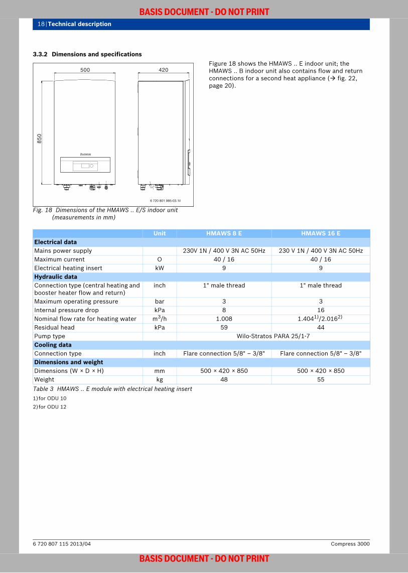
Fig. 18 Dimensions of the HMAWS .. E/S indoor unit(measurements in mm)
Figure 18 shows the HMAWS .. E indoor unit; the HMAWS .. B indoor unit also contains flow and return connections for a second heat appliance ( fig. 22, page 20).
6 720 801 985-03.1il
420500
85
0
Unit HMAWS 8 E HMAWS 16 EElectrical dataMains power supply 230V 1N / 400 V 3N AC 50Hz 230 V 1N / 400 V 3N AC 50HzMaximum current O 40 / 16 40 / 16Electrical heating insert kW 9 9Hydraulic dataConnection type (central heating and booster heater flow and return)
inch 1" male thread 1" male thread
Maximum operating pressure bar 3 3Internal pressure drop kPa 8 16Nominal flow rate for heating water m3/h 1.008 1.4041)/2.0162)
Residual head kPa 59 44Pump type Wilo-Stratos PARA 25/1-7Cooling dataConnection type inch Flare connection 5/8" – 3/8" Flare connection 5/8" – 3/8"Dimensions and weightDimensions (W × D × H) mm 500 × 420 × 850 500 × 420 × 850Weight kg 48 55Table 3 HMAWS .. E module with electrical heating insert1)for ODU 102)for ODU 12
Compress 30006 720 807 115 2013/04
BASIS DOCUMENT - DO NOT PRINT
Technical description | 19
BASIS DOCUMENT - DO NOT PRINT
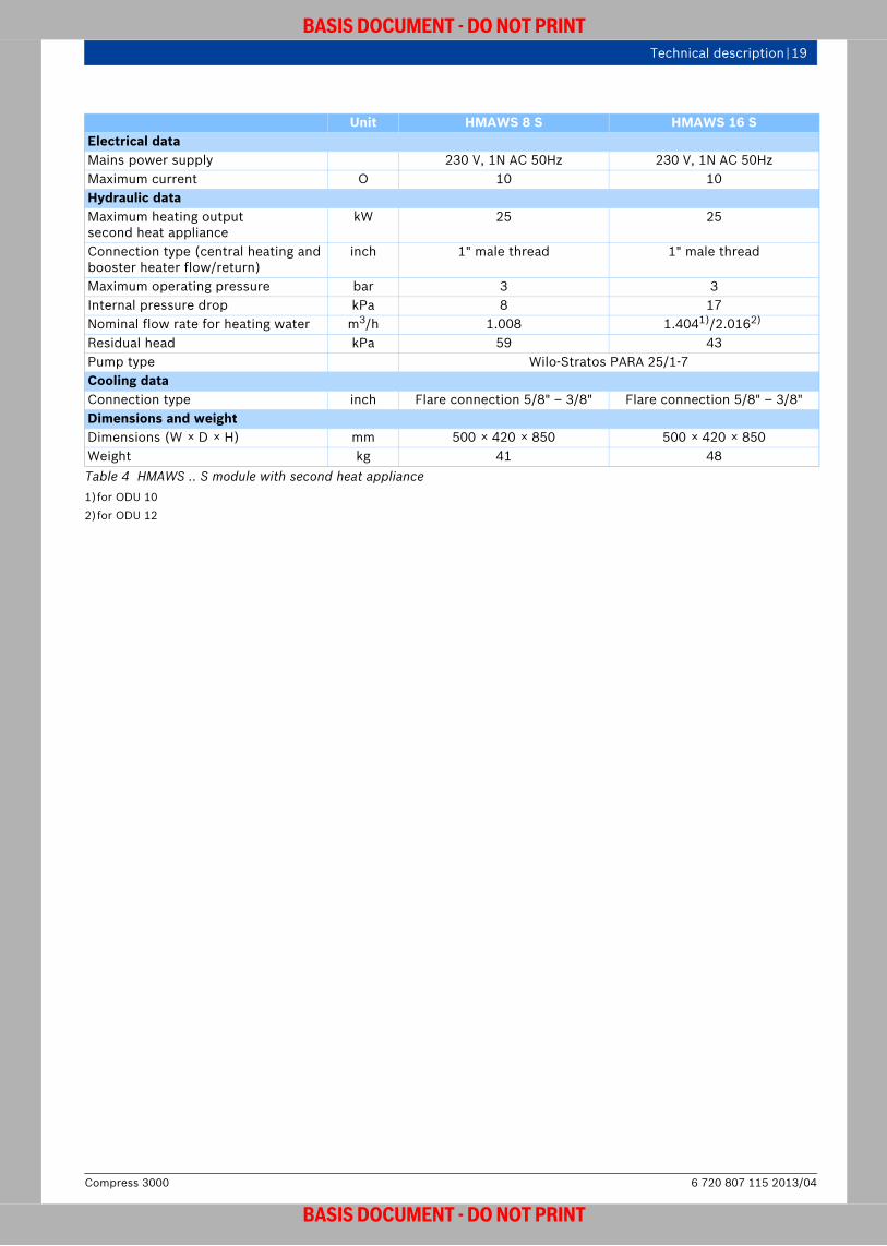
Unit HMAWS 8 S HMAWS 16 SElectrical dataMains power supply 230 V, 1N AC 50Hz 230 V, 1N AC 50HzMaximum current O 10 10 Hydraulic dataMaximum heating outputsecond heat appliance
kW 25 25
Connection type (central heating and booster heater flow/return)
inch 1" male thread 1" male thread
Maximum operating pressure bar 3 3Internal pressure drop kPa 8 17Nominal flow rate for heating water m3/h 1.008 1.4041)/2.0162)
Residual head kPa 59 43Pump type Wilo-Stratos PARA 25/1-7Cooling dataConnection type inch Flare connection 5/8" – 3/8" Flare connection 5/8" – 3/8"Dimensions and weightDimensions (W × D × H) mm 500 × 420 × 850 500 × 420 × 850Weight kg 41 48Table 4 HMAWS .. S module with second heat appliance 1)for ODU 102)for ODU 12
6 720 807 115 2013/04Compress 3000
BASIS DOCUMENT - DO NOT PRINT
20 | Technical description
BASIS DOCUMENT - DO NOT PRINT
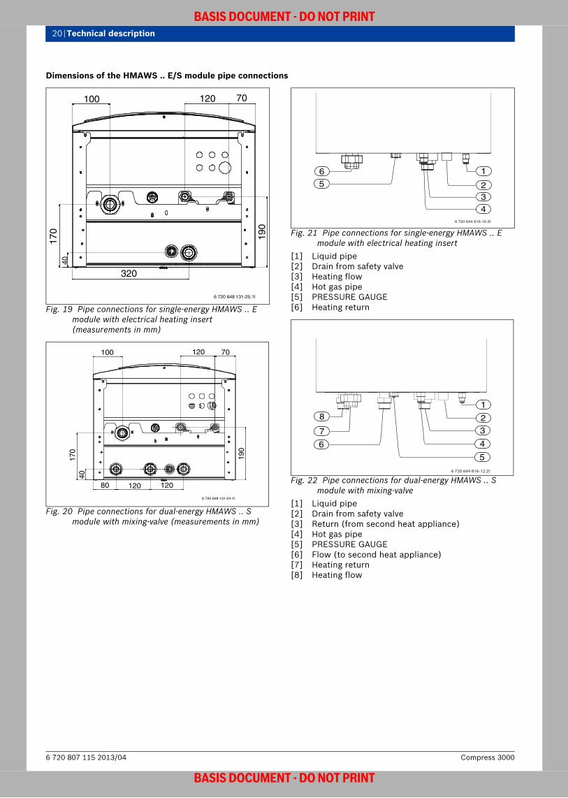
Dimensions of the HMAWS .. E/S module pipe connections
Fig. 19 Pipe connections for single-energy HMAWS .. E module with electrical heating insert (measurements in mm)
Fig. 20 Pipe connections for dual-energy HMAWS .. S module with mixing-valve (measurements in mm)
Fig. 21 Pipe connections for single-energy HMAWS .. E module with electrical heating insert
[1] Liquid pipe [2] Drain from safety valve[3] Heating flow[4] Hot gas pipe [5] PRESSURE GAUGE[6] Heating return
Fig. 22 Pipe connections for dual-energy HMAWS .. S module with mixing-valve
[1] Liquid pipe [2] Drain from safety valve[3] Return (from second heat appliance)[4] Hot gas pipe [5] PRESSURE GAUGE[6] Flow (to second heat appliance)[7] Heating return[8] Heating flow
190
320
40
170
100 120 70
6 720 648 131-25.1I
190
12012080
4017
0
100 120 70
6 720 648 131-24.1I
3
6 720 644 816-16.2I
1
5
4
6
2
6
7
5
8
3
1
4
2
6 720 644 816-12.2I
Compress 30006 720 807 115 2013/04
BASIS DOCUMENT - DO NOT PRINT
Technical description | 21
BASIS DOCUMENT - DO NOT PRINT
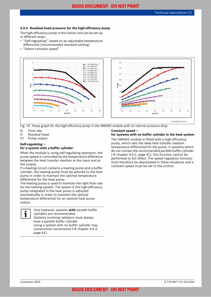
3.3.3 Residual head pressure for the high-efficiency pump The high-efficiency pump in the indoor unit can be set up in different ways:• “Self-regulating”, based on an adjustable temperature
differential (recommended standard setting)• “Select constant speed”
Fig. 23 Pump graph for the high-efficiency pump in the HMAWS module with no internal pressure drop Q Flow rateH Residual headP1 Pump output
Self-regulating – for a system with a buffer cylinderWhen the module is using self-regulating operation, the pump speed is controlled by the temperature difference between the heat transfer medium at the input and at the output. If a heating circuit contains a heating pump and a buffer cylinder, the heating pump must be attuned to the heat pump in order to maintain the optimal temperature differential for the heat pump.The heating pump is used to maintain the right flow rate for the heating system. The speed of the high-efficiency pump integrated in the heat pump is adjusted automatically in order to maintain the optimal temperature differential for an optimal heat pump output.
Constant speed –for systems with no buffer cylinder in the heat systemThe HMAWS module is fitted with a high-efficiency pump, which sets the ideal heat transfer medium temperature differential for the pump. In systems which do not contain the recommended parallel buffer cylinder ( chapter 4.6.2, page 41), this function cannot be performed to full effect. The speed regulation function must therefore be deactivated in these situations and a constant speed must be set in the control.
0
1
2
3
4
5
6
7
8
0,0 0,5 1,0 1,5 2,0 2,5 3,0 3,5 4,0
Q [m³/h]
H [m
]
U = 10V (4450 rpm)U = 9V (3990 rpm)U = 8V (3520 rpm)U = 7V (3060 rpm)U = 6V (2590 rpm)U = 5V (2200 rpm)U = 4V (1660 rpm)U = 3V (1200 rpm)U = 10V (4450 rpm)
0
10
20
30
40
50
60
70
80
0,0 0,5 1,0 1,5 2,0 2,5 3,0 3,5 4,0
Q [m³/h]
P1 [W
]
6 720 648 125-74.1I
Only hydraulic systems with parallel buffer cylinders are recommended.Systems involving radiators must always have a parallel buffer cylinder.Using a system with no buffer cylinder may compromise convenience ( chapter 4.6.2, page 41).
6 720 807 115 2013/04Compress 3000
BASIS DOCUMENT - DO NOT PRINT

22 | Planning and design of the heat pump system
BASIS DOCUMENT - DO NOT PRINT
4 Planning and design of the heat pump system
4.1 Planning steps (overview)The steps required to plan and design a heating system containing a heat pump are shown in fig. 24. A detailed description can be found in the following chapters.
Comment: Planning can be done using VPW2100 instead.
Comment: DIN only applicable in Germany.
Comment: EVU only applicable in Germany.
Fig. 24
Berechnung des Energiebedarfs
Heizungwird berechnet mit
Warmwasser
Betriebsweise
Sperrzeiten EVU
Geräteauswahl
1 Heizkreis
2 Heizkreise
Warmwasserbereitung
Pufferspeicher
Anlagentypen
bivalenter Betrieb
Planungsbeispiele (Auswahl der Anlagenhydraulik)
Auslegung und Auswahl der Wärmepumpe
monoenergetisch bivalent
DIN EN 12831, Faustformel
wird berechnet mitDIN 4708, Faustformel
6 720 801 985-20.1il
Compress 30006 720 807 115 2013/04
BASIS DOCUMENT - DO NOT PRINT

Planning and design of the heat pump system | 23
BASIS DOCUMENT - DO NOT PRINT
4.2 Determining the building heat load (heat demand)
Comment: Planning can be done using VPW2100 instead.
Comment: Most of the content is this section is only valid in Germany.
The precise heat load is calculated based on DIN EN 12831. The descriptions below relate to rough methods which can be used to provide an estimate but which cannot take the place of detailed, individual calculations.
4.2.1 Existing buildingsWhen replacing an existing heating system, the heat load can be estimated based on the fuel consumption of the old heating system.For gas heating systems (Verbrauch = consumption):
Form. 6For oil heating systems:
Form. 7
Example:30,000 litres of fuel oil were needed over the past 10 years to heat a house. How great is the heat load?The average fuel oil consumption per year is as follows:
The heat load is thus calculated as follows:
The heat load can also be calculated as shown in chapter 4.2.2. The reference values for the specific heat demand are then as follows:
4.2.2 New buildingsThe required output for heating a residential unit or house can be roughly estimated based on the area to be heated and the specific heat demand. The specific heating output demand depends on the building's thermal insulation ( tab. 6).
The heating output demand (Q) is calculated from the heated area (A) and the specific heat load (heating output demand) (q) as follows:
Form. 8
ExampleHow great is the heat load for a house with 150 m2 area to be heated and thermal insulation to EnEV 2009?For insulation to EnEV 2009, tab. 6 lists a specific heat load of 30 W/m2. The heat load is thus calculated as follows:
To compensate for extremely cold or hot years, the average fuel consumption for several years must be determined.
Q [kW] Consumption m3 a
250 m3/a kW-------------------------------------------------------------------------=
Q [kW] Verbrauch l a 250 l a kW
--------------------------------------------------------=
Verbrauch l/a Verbrauch [l/a]Zeitraum a
------------------------------------------------------ 30000 Liter10 Jahre----------------------------------------= =
3000 l/a=
Q [kW] 3000 l/a250 l a kW----------------------------------------- 12 kW= =
Type of building insulation
Specific heat load q [W/m2]
Insulation to German Thermal Insulation Ordinance (WSchVO) 1982
60 - 100
Insulation to German Thermal Insulation Ordinance (WSchVO) 1995
40 - 60
Table 5 Specific heat demand
Type of building insulation
Specific heat load q [W/m2]
Insulation to EnEV 2002 40 - 60
Insulation in accordance with German Energy Savings Order 2009 KfW efficiency house 100
30 - 35
KfW efficiency house 70 15 - 30
Ultra-low energy building 10
Table 6 Specific heat demand
Q [W] A m2 q W/m2 =
Q 150 m2 30 W m2=
4500 W = 4,5 kW=
6 720 807 115 2013/04Compress 3000
BASIS DOCUMENT - DO NOT PRINT

24 | Planning and design of the heat pump system
BASIS DOCUMENT - DO NOT PRINT
4.2.3 Additional output for DHW heatingIf the heat pump is also to be used for DHW heating, the required additional output must be taken into account during the design phase.The required heating output for DHW heating depends primarily on the DHW demand. This will vary according to the number of people in the household and the desired DHW convenience.In normal residential units, a per-person consumption of 30 to 60 litres of domestic hot water at a temperature of 45 °C is assumed.To be on the safe side during system planning and meet increased consumer requirements for convenience, a heating output of 200 W per person is used.
Example:How great is the additional heating output for a four-person household with a DHW demand of 50 litres per person and day?
The additional heating output per person is 0.2 kW. In a four-person household the additional heating output is therefore calculated as follows:
4.2.4 Additional output for blocking times imposed by the energy supplier
Comment: Only applicable in Germany and Czech republic.
Many energy suppliers encourage users to install heat pumps by providing special electricity tariffs. In return for the lower prices, the energy suppliers reserve the right to impose blocking times for heat pump operation, e.g. when there are high output peaks in the mains supply.
Single-energy operationIn the case of single-energy operation, the heat pump must be made larger in order to cover the heat demand required over the course of a day in spite of the blocking times. In theory, the factor for the heat pump design is calculated as follows:
Form. 9In practice, however, the additional output required is lower than this factor because it is never necessary to heat every room and the lowest outside temperatures are rarely reached.
The following sizing has been proven to work in practical applications:
It is therefore sufficient to make the heat pump around 5 % (2 blocking hours) to 15 % (6 blocking hours) larger.
dual-energy operationIn the case of dual-energy operation, the blocking times do not generally cause any problems because the second heat appliance starts up if necessary.
QWW 4 0,2 kW 0,8 kW==
f 24 h24 h Sperrzeit pro Tag [h]–-------------------------------------------------------------------------------------------------=
Total blocking time per day [h]
Additional heat output[% of the heat load]
2 54 106 15Table 7
Compress 30006 720 807 115 2013/04
BASIS DOCUMENT - DO NOT PRINT

Planning and design of the heat pump system | 25
BASIS DOCUMENT - DO NOT PRINT
4.3 Heat pump designAir to water heat pumps are generally designed in the following operating modes:• Single-energy operating mode
The majority of the building heat load and the heat load for DHW heating is covered by the heat pump. When demand peaks, an electrical heating insert steps in.
• dual-energy operating modeThe majority of the building heat load and the heat load for DHW heating is covered by the heat pump. When demand peaks, an additional heat appliance (e.g. an oil boiler) steps in. dual-energy operation heat pumps are well-suited to refurbishment projects for existing heating systems.
4.3.1 Single-energy operation of ..E split-version air to water heat pumps
Single-energy operation always takes into account the fact that peak outputs are covered with the help of an electrical heating insert, and not by the heat pump alone. The insert supports both the central heating and the DHW heating as needed. The output required in each case is provided in progressive stages (up to 9 kW). It is important to design the system in such a way that the proportion of direct electrical energy supplied is as small as possible. If a heat pump is clearly too small, the electrical heating insert will have to perform a large share of the work, leading to an undesirable increase in electricity costs.It is also important to bear in mind the operating range of the heat pump ( Specifications). Beyond this operating range, only the electrical heating insert will be operating. It is a good idea to avoid this situation by choosing suitable heating systems. Hence, the maximum required heating flow temperature should not exceed the maximum flow temperature of the heat pump, which is dependent on the outside temperature.
Comment: Text below valid only in Germany.
The outside temperatures in Germany depend on local climatic conditions. However, given that the outside temperature only drops below –5 °C for around 20 days a year on average, a parallel heating system – such as an electrical heating insert – is only required to support the heat pump for a few days a year.
Comment: DIN only applicable in Germany.
We recommend the following values for switching over to dual-energy operation: • –4 °C to –7 °C at a standard outside temperature of
–16 °C (according to DIN EN 12831) • –3 °C to –6 °C at a standard outside temperature of
–12 °C (according to DIN EN 12831)• –2 °C to –5 °C at a standard outside temperature of
–10 °C (according to DIN EN 12831)An electrical heating insert with a maximum output of 9 kW is already integrated in the HMAWS ..E. The output of the electrical heating insert is controlled in 3-kW stages according to demand.
Example:
Comment: Calculations can be done using VPW2100.
What output is required from the heat pump system for:• A building with a living space of 150 m2
• 30 W/m2 specific heat load• Standard outside temperature –12 °C• 4 people with a DHW demand of 50 litres per dayThe heat load is calculated as follows:
The additional heat output for DHW heating is 200 W per person per day. In a four-person household, the additional heat output is therefore calculated as follows:
The total heat load for central heating and DHW heating is therefore:
The dual-energy switch-over point can be set at lower temperatures for houses with low heat demands ( fig. 26, page 27).
QH 150 m2 30 W m2=
4500 W=
QWW 4 200 W 800 W==
QHL QH QWW+=
4500 W 800 W+ 5300 W==
6 720 807 115 2013/04Compress 3000
BASIS DOCUMENT - DO NOT PRINT

26 | Planning and design of the heat pump system
BASIS DOCUMENT - DO NOT PRINT
4.3.2 dual-energy operation of ..S split-version air to water heat pumpsdual-energy operation always requires a second heat appliance, e.g. an oil boiler or a gas boiler.The HMAWS .. S works as a parallel or partially parallel dual-energy system. The HMAWS series can work without setting a dual-energy switch-over point at all, because the control can calculate the point by itself based on the heat demand.The second heat appliances are therefore only activated if necessary. There is no longer any need to classify the operating modes as before, e.g. parallel dual-energy or alternating dual-energy.The installer can adjust the temperature window for independent activation of the second heat appliance in the control using the parameters “Maximum outside temperature for booster heaters” (first dual-energy switch-over point) and “Minimum outside temperature of the heat curve” (second dual-energy switch-over point) as required.
This results in three ranges in which the heat pump is operated ( fig. 25):• (1) Above the “Maximum outside temperature for
booster heaters” (first dual-energy switch-over point), the heat pump will cover the heat demand of the heating system by itself.
• (2) Between the two temperatures (range between first and second dual-energy switch-over points), the heat pump covers the heat demand and the second heat appliance is only switched on to help if necessary. In addition, the heat pump can be deactivated within this range if the conditions checked by the control no longer warrant efficient, parallel operation.
• (3) Below the “Minimum outside temperature of the heat curve” (second dual-energy switch-over point), the second heat appliance covers the entire heat demand of the heating system by itself.
Comment: This is shown in VPW2100.
Fig. 25 HMAWS .. S operating ranges and dual-energy switch-over pointsQ Heat load
Arbeitsanteil zweiter Wärmeerzeuger
Arbeitsanteil Wärmepumpe
Heiztage pro Jahr (%)
Betrieb Wärmepumpe
bedarfs- und effizienz-abhängiger Betrieb vonWärmepumpe und/oder zweitem Wärmeerzeuger
1. Bivalenzpunkt2. Bivalenzpunkt
100
100
Q (%)
BetriebzweiterWärmeerzeuger
00
12
3
6 720 801 984-43.2il
Compress 30006 720 807 115 2013/04
BASIS DOCUMENT - DO NOT PRINT
Planning and design of the heat pump system | 27
BASIS DOCUMENT - DO NOT PRINT
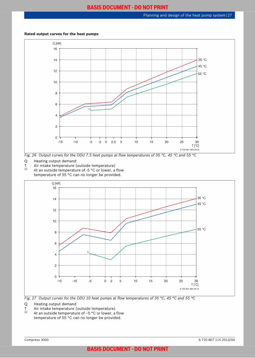
Rated output curves for the heat pumps
Fig. 26 Output curves for the ODU 7.5 heat pumps at flow temperatures of 35 °C, 45 °C and 55 °CQ Heating output demandT Air intake temperature (outside temperature)1) At an outside temperature of -5 °C or lower, a flow
temperature of 55 °C can no longer be provided.
Fig. 27 Output curves for the ODU 10 heat pumps at flow temperatures of 35 °C, 45 °C and 55 °CQ Heating output demandT Air intake temperature (outside temperature)1) At an outside temperature of –5 °C or lower, a flow
temperature of 55 °C can no longer be provided.
6 720 801 984-08.2il
0
2
4
61)
8
10
12
14
16
-15 -10 -5 0 52,5-2 10 15 20 25 30
35 °C
45 °C
55 °C
Q [kW]
T [°C]
6 720 801 984-09.1il
0
2
4
6
8
10
12
14
16
-15 -10 -5 0 52 10 15 20 25 30
35 °C
45 °C
55 °C
Q [kW]
T [°C]
1)
6 720 807 115 2013/04Compress 3000
BASIS DOCUMENT - DO NOT PRINT

28 | Planning and design of the heat pump system
BASIS DOCUMENT - DO NOT PRINT
Fig. 28 Output curves for the ODU 12 heat pumps at flow temperatures of 35 °C, 45 °C and 55 °CQ Heating output demandT Air intake temperature (outside temperature)1) At an outside temperature of –5 °C or lower, a flow
temperature of 55 °C can no longer be provided.
4.3.3 Thermal insulationAll hot and cold pipes are to be thermally insulated as required by the relevant standards.If the HMAWS .. E is also used for cooling, all pipework and components must be insulated accordingly in order to eliminate the possibility of condensation.
4.3.4 Expansion vessel When refurbishing old systems, it may be necessary to install an additional expansion vessel (on site) due to the high water capacity.
6 720 801 984-10.1il
35 °C
45 °C
55 °C
0
2
4
6
8
10
12
14
16
18
20
-15 -10 -5 0 5 10 15 20 25 30T [°C]
Q [kW]
1)
Compress 30006 720 807 115 2013/04
BASIS DOCUMENT - DO NOT PRINT

Planning and design of the heat pump system | 29
BASIS DOCUMENT - DO NOT PRINT
4.4 Design for cooling mode (only HMAWS .. E)HMAWS E are reversible heat pumps. By running the heat pump circuit process in the other direction (reversible operation), the heat pumps can also be used for cooling. Cooling can be carried out via an underfloor heating system or a separate cooling circuit, such as a cooling convector.In order to prevent condensate from forming, a buffer cylinder with diffusion-resistant thermal insulation must be used in cooling mode (e.g. P50 W). All installed components, such as pipes, pumps, etc., must also be thermally insulated and resistant to vapour diffusion. The HMAWS 8/16 E indoor unit is already thermally insulated and resistant to vapour diffusion as standard when it leaves the factory.In the case of refurbishments (HMAWS .. S), there is generally no cooling process. For this reason, the HMAWS 8/16 S is not insulated as standard and is therefore not suitable for cooling. In order to carry out cooling with the HMAWS .. S, the indoor unit must be insulated on site and the system must be monitored for condensation. Cooling using radiators is not permitted.Cooling mode is monitored by the main circuit (T1, flow temperature sensor and T5, room temperature sensor). Cooling exclusively via circuit 2 is therefore not possible. The “Block cooling in heating circuit 1” function also blocks the cooling in circuit 2.Two different operating modes are available for cooling:• Cooling above the dew point,
e.g. cooling using an underfloor heating system: For operation above the dew point, e.g for cooling using the underfloor heating system, dew point sensors (up to 5) must be installed in the most critical areas of the pipework. The sensors will switch the heat pump off immediately if condensate forms in order to prevent damage to the house.- or -
• Cooling below the dew point, e.g. cooling with fan convectors:For operation below the dew point (adjustable down to +5 °C), the entire heating system must be insulated against condensation and a suitable heating buffer cylinder must be used. Any condensate that forms – in fan convectors, for example – must be conveyed away.
We do not recommend cooling below the dew point.
A CAN-BUS programming unit (with humidity sensor) must be used for cooling:• For weather-compensated cooling with room
influence or room-temperature-compensated cooling using an underfloor heating circuit
• For cooling via a separate cooling circuit, e.g. a cooling convector
Cooling using an underfloor heating systemAs well as heating rooms, an underfloor heating system can also be used for cooling. The cooling capacity can be controlled by means of a cooling characteristic curve – similar to a heating curve. In cooling mode, the surface temperature of the underfloor heating system should not drop below 20 °C. In order to meet the criteria for comfort and to prevent the formation of condensation, the surface temperature limits must be observed. A dew point sensor must be installed in the flow of the underfloor heating system in order to detect the dew point. This can prevent the formation of condensate, even in the case of brief fluctuations in the weather. The minimum flow temperature for cooling with an underfloor heating system and the minimum surface temperature are dependent on the climatic conditions in the room (air temperature and relative air humidity). These values must be taken into account when planning a system.
Underfloor heating circuits in humid rooms (e.g. bathroom or kitchen) must not be used for cooling because of the risk of condensation.
6 720 807 115 2013/04Compress 3000
BASIS DOCUMENT - DO NOT PRINT

30 | Planning and design of the heat pump system
BASIS DOCUMENT - DO NOT PRINT
Cooling load calculation
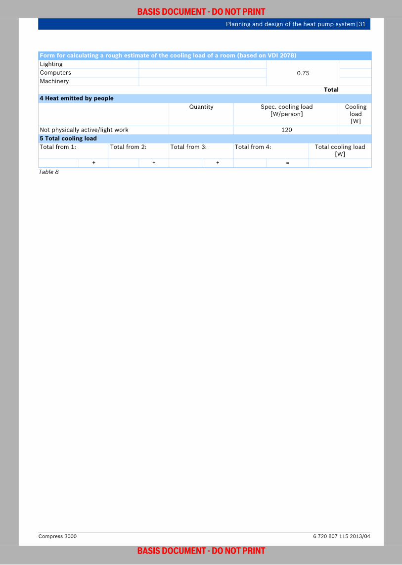
Comment: VDI 2078 only valid in Germany.The precise cooling load can be calculated by following VDI 2078. The following form can be used to provide a rough estimate of the cooling load (based on VDI 2078).
Form for calculating a rough estimate of the cooling load of a room (based on VDI 2078)Address Description of roomName: Length: Area:Street: Width: Volume:Town: Height Use:1 Solar radiation through windows and external doorsDirection Unscreened window Reduction factor for sunblind
Single glazing[W/m2]
Double glazing[W/m2]
Insulation glazing[W/m2]
Interior blind
Awning Exterior blind
Specific cooling load
[W/m2]
Window area [m2]
Window area [m2]
NorthNortheastEastSoutheastSouthSouthwestWestNorthwestSkylight
6580310270350310320250500
6070
280240300280290240380
3540155135165155160135220
x 0.7 x 0.3 x 0.15
Total2 Walls, floor, ceiling minus the window and door openings already mentionedExternal wall Direction
Sunny [W/m2]
Shady[W/m2]
Specific cooling load
[W/m2]Area[m2]
Cooling load [W]
North, eastSouthWest
123035
121717
Internal wall connected to non-air-conditioned rooms 10Floor connected to non-air-conditioned rooms 10Ceiling Connected to non-
air-conditioned room
[W/m2]
Non-insulated[W/m2]
Insulated[W/m2]
Flat roof Pitched roof
Flat roof Pitched roof
10 60 50 30 25Total
3 Electrical appliances in operationConnected load
[W]Reduction factor Cooling
load [W]
Table 8
Compress 30006 720 807 115 2013/04
BASIS DOCUMENT - DO NOT PRINT
Planning and design of the heat pump system | 31
BASIS DOCUMENT - DO NOT PRINT
Lighting0.75Computers
MachineryTotal
4 Heat emitted by peopleQuantity Spec. cooling load
[W/person]Cooling
load [W]
Not physically active/light work 1205 Total cooling loadTotal from 1: Total from 2: Total from 3: Total from 4: Total cooling load
[W]+ + + =
Form for calculating a rough estimate of the cooling load of a room (based on VDI 2078)
Table 8
6 720 807 115 2013/04Compress 3000
BASIS DOCUMENT - DO NOT PRINT

32 | Planning and design of the heat pump system
BASIS DOCUMENT - DO NOT PRINT
4.5 Installing the Compress 3000
4.5.1 Fundamental requirements for the installation location
The installation location must fulfil the following requirements:• The heat pump must be accessible from all sides.• The distance between the heat pump and the walls,
walkways, terraces, etc. must not be less than the minimum requirement ( page 35) in order to avoid air short circuits.
• The heat pump must not be installed in a sink, because the cold air will sink and prevent air exchange from taking place.
• Always observe the maximum length for the refrigerant pipes.
• Do not install the Heat pump with the exhaust side facing the primary wind direction. If the pump is installed in a location exposed to the wind, on-site measures must be taken to prevent the wind affecting the fan area.
• Observe wind loads.• Do not install the heat pump in corners or recesses, as
this can lead to increased noise levels.• Do not install the heat pump next to or under bedroom
windows.Requirements for installation inside the building(indoor unit)• A wastewater connection must be provided for the
safety valve. The discharge hose for the safety valve must be connected to the public sewage system on a slope and with pipe ventilation.
• Shut-off devices must be provided for the heating water flow and the shared heating water return/DHW cylinder return.
• Rooms in which the HMAWS module or the refrigerant pipes are installed, and which can accommodate people, must have a volume of at least 5.7 m³.
• The installation room must be dry and free from the risk of frost.
• Ambient temperatures of 0 to 35 °C and dry air (max. air humidity 20 g/kg) must be ensured.
• The room must comply with the minimum volume requirements (according to DIN EN 378) ( tab. 11).
Installing the ODU outdoor unit on the floor (ground)• The heat pump is to be installed on a permanently
fixed, level, flat and horizontal surface. We recommend that you install the outdoor unit on a poured concrete slab or on paving slabs with an anti-frost layer.
• In order to install the outdoor unit on the floor using a floor stand, the floor must be level and have a sufficient load bearing capacity for the outdoor unit and the condensate pan.
Mounting the ODU outdoor unit on the wall• Due to the increased risk of structure-borne noise, the
outdoor unit should only be mounted on a wall if it is not possible to install it on the floor.
• Mounting the indoor unit on the wall requires a wall mounting bracket ( accessory; the wall mounting bracket available as an accessory can only be used in combination with the ODU 7.5).
• The wall must have a sufficient load bearing capacity for the outdoor unit, the wall mounting panel and the condensate pan, and must be able to absorb vibrations. It is important to prevent structure-borne noise so that those inside the building are not disturbed. The heat pump should not be mounted on a wall next to living rooms or bedrooms.
• For walls with upgraded installation, on-site measures must be taken to ensure that the outdoor unit is fixed securely.
Air discharge and intake sides• The air intake and discharge sides must be kept free all
year round and must not be contaminated by leaves or blocked by snow.
• The air blown out from the discharge area of the heat pump is around 5 K cooler than the ambient temperature. This means that ice may form early in this area. Therefore, the discharge area must not be situated right next to walls, terraces, walkways, rainwater pipes or sealed surfaces (distance > 3 metres).
ODU outdoor unit Weight[kW] [kg] 7.5 67 10 116 11 126 12 132
Table 9 Weight of the ODU outdoor unit
Compress 30006 720 807 115 2013/04
BASIS DOCUMENT - DO NOT PRINT
Planning and design of the heat pump system | 33
BASIS DOCUMENT - DO NOT PRINT
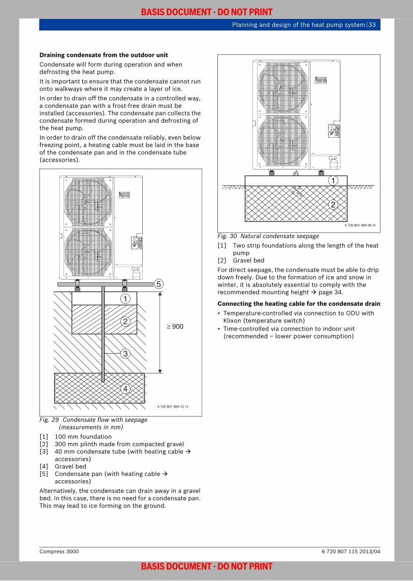
Draining condensate from the outdoor unitCondensate will form during operation and when defrosting the heat pump.It is important to ensure that the condensate cannot run onto walkways where it may create a layer of ice.In order to drain off the condensate in a controlled way, a condensate pan with a frost-free drain must be installed (accessories). The condensate pan collects the condensate formed during operation and defrosting of the heat pump. In order to drain off the condensate reliably, even below freezing point, a heating cable must be laid in the base of the condensate pan and in the condensate tube (accessories).
Fig. 29 Condensate flow with seepage(measurements in mm)
[1] 100 mm foundation[2] 300 mm plinth made from compacted gravel[3] 40 mm condensate tube (with heating cable
accessories)[4] Gravel bed[5] Condensate pan (with heating cable
accessories)Alternatively, the condensate can drain away in a gravel bed. In this case, there is no need for a condensate pan. This may lead to ice forming on the ground.
Fig. 30 Natural condensate seepage [1] Two strip foundations along the length of the heat
pump[2] Gravel bedFor direct seepage, the condensate must be able to drip down freely. Due to the formation of ice and snow in winter, it is absolutely essential to comply with the recommended mounting height page 34.
Connecting the heating cable for the condensate drain• Temperature-controlled via connection to ODU with
Klixon (temperature switch)• Time-controlled via connection to indoor unit
(recommended – lower power consumption)≥ 900
4
5
1
2
3
6 720 801 984-12.1il
6 720 801 984-36.1il
1
2
6 720 807 115 2013/04Compress 3000
BASIS DOCUMENT - DO NOT PRINT

34 | Planning and design of the heat pump system
BASIS DOCUMENT - DO NOT PRINT
Foundation
Fig. 31 Foundations for the outdoor unit [1] > 150 mm[2] Level subsurface with sufficient load bearing
capacity, e.g. poured cement slab[3] Ventilation hole, must not be obstructed• The installation surface must be level and firm and
have a sufficient load bearing capacity.• Wooden bases are not suitable.• Requirements for concrete foundations:
– Thickness of concrete 100 mm– Load bearing capacity 320 kg
• The recommended mounting height is at least 150 mm above the ground in order to compensate for ice formation. In areas that experience frequent snowfall, the minimum distances are to be increased accordingly.
Minimum room volume for the indoor unitAccording to EN 378, the minimum volume of the installation room depends on the fill volume and the composition of the refrigerant, and can be calculated using the following formula:
Form. 10Vmin Minimum room volume in m3
mmax Max. refrigerant fill volume in kgG Practical limit according to DIN EN 378,
depending on the composition of the refrigerant
The refrigerant used, together with the fill volumes, produces the following minimum room volumes:
For pipe lengths > 30 m, the refrigerant must be topped up. This increases the minimum room volume according to the amount by which the refrigerant is topped up.
2
6720644816-09.1I
1
3
Refrigerant Practical limit[kg/ m³]
R410A 0.44Table 10
When several heat pumps are installed in one room, the minimum room volumes for the individual heat pumps must be added together in order to calculate the total minimum volume.
Type Minimum room volumeODU [ m³]7.5 8.010/11 11.412 11.4Table 11 Minimum room volume
Vminmmax
G------------------=
Compress 30006 720 807 115 2013/04
BASIS DOCUMENT - DO NOT PRINT

Planning and design of the heat pump system | 35
BASIS DOCUMENT - DO NOT PRINT
4.5.2 Minimum clearances
ODU outdoor unit
Fig. 32 Minimum clearances for the ODU outdoor unit (measurements in mm)
The minimum clearance between the heat pump and the wall is 150 mm. The minimum clearance in front of the heat pump is 500 mm for the ODU 7.5 and ODU 10, 11, and 1000 mm for the ODU 12t. Minimum clearance of 150 mm at the sides. If a protective cover is to be installed, there must be a working clearance of 1 m between it and the heat pump in order to prevent cold air from circulating.
HMAWS module
Fig. 33 Minimum clearances for the HMAWS module (measurements in mm)
Dimensions of the pipe connections for theHMAWS .. E/S module page 20.
The outdoor unit must be installed in such a way as to prevent cold air recirculating.
150
150
1000
150
6720648125-07.1I
50
600
6 720 644 816-11.1I
50
150
6 720 807 115 2013/04Compress 3000
BASIS DOCUMENT - DO NOT PRINT

36 | Planning and design of the heat pump system
BASIS DOCUMENT - DO NOT PRINT
Connecting the HMAWS module to the ODU outdoor unit
Wall outlets are required in order to lay the refrigerant pipework and to establish electrical connections between the ODU outdoor unit and the HMAWS module inside the building. These outlets must take into account the position of load-bearing structures, lintels, materials used to provide impermeability (e.g. vapour barriers), etc. Please note the information provided by the manufacturer of the wall outlet and ensure that the outlets are properly installed by an expert.
Refrigerant pipesThe outdoor unit comes pre-charged with R410A refrigerant (enough for both refrigerant pipes at a length of up to 30 m per pipe). The two appliances are connected via the hot gas and liquid pipes using flare connections.Please bear in mind the following conditions when planning the refrigerant pipes:• The maximum pipe lengths and the amounts by which
the refrigerant may need to be topped up can be found in tab. 12.
• The maximum distance and height difference between the ODU outdoor unit and the HMAWS module must be observed ( tab. 18, page 44).
• The connections should be as short and direct as possible.
• Only copper pipes which are approved for use with the R410A refrigerant may be used (internal diameter Specifications).
• The suction pipe and liquid pipe must be thermally insulated individually. The thermal insulation must be closed-cell, diffusion-resistant and at least 6 mm thick.
HMAWS module and ODU outdoor unit on the same level
Fig. 34 HMAWS module and ODU outdoor unit on the same level
[1] HMAWS module[2] ODU outdoor unit[3] Hot gas pipe[4] Liquid pipe
Only trained specialists are authorised to carry out work on the refrigerant connections in accordance with the current EU directives (EC Regulation No. 842/2006 on F-gases, which came into force on 4th July 2006). Violation of this rule will void the warranty. Alternatively, work on refrigerant connections can be carried out by the Bosch service department.
Model Permitted pipe length
Permitted difference vertically
Top up amount of refrigerant
0 – 30 m31 – 40 m 41 – 50 m 51 – 60 m 61 – 75 m
8 0 – 50 m 0,6 kg 1,2 kg – –11 – 16 0 – 75 m 0,6 kg 1,2 kg 1,8 kg 2,4 kg
Table 12 Topping up refrigerant
6 720 801 984-14.1il
2
3 4
1
Compress 30006 720 807 115 2013/04
BASIS DOCUMENT - DO NOT PRINT
Planning and design of the heat pump system | 37
BASIS DOCUMENT - DO NOT PRINT
4.5.3 Sound insulation requirements
Technical principles of sound and terminologyTab. 13 explains the most important technical principles and terminology relating to sound, which are used below.
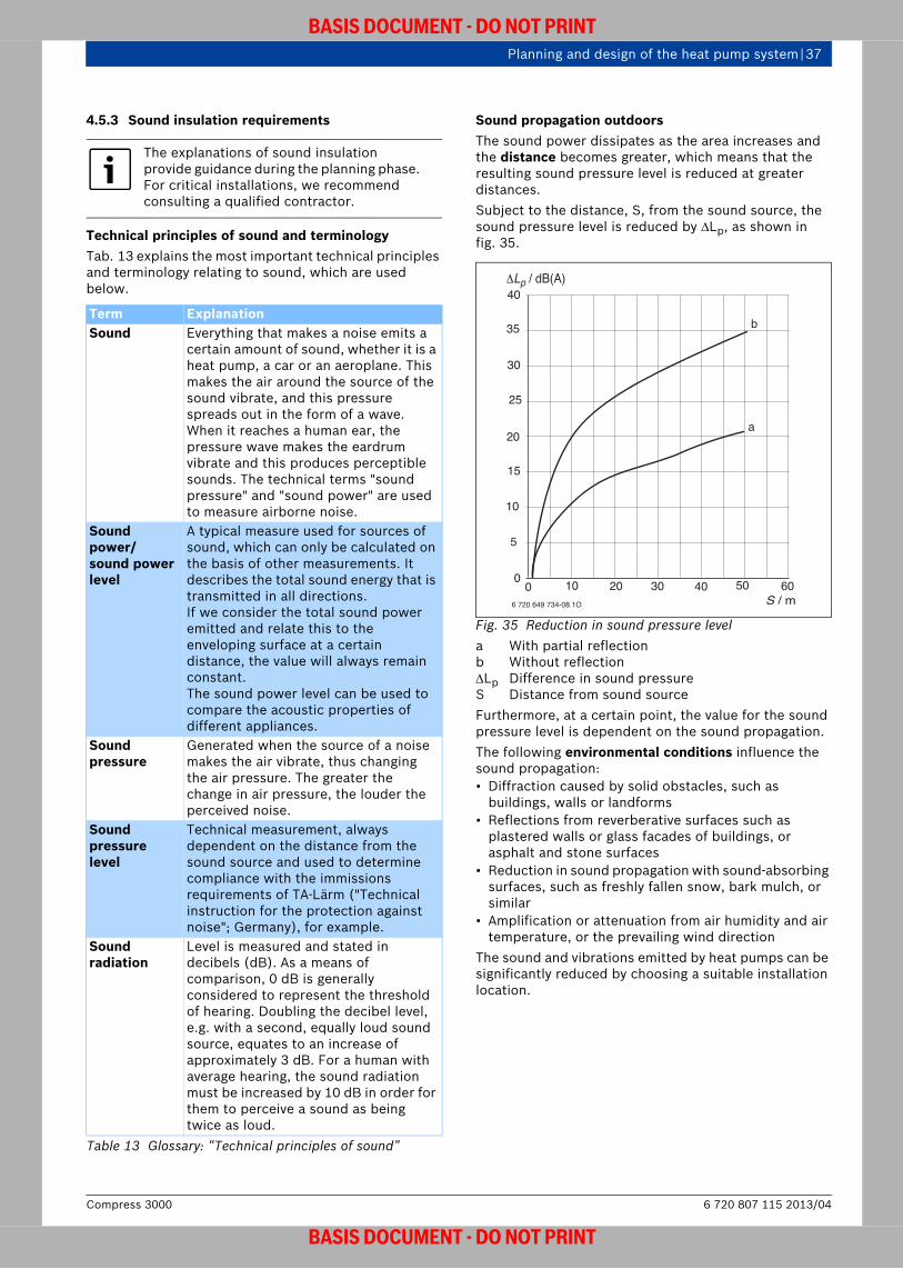
Sound propagation outdoorsThe sound power dissipates as the area increases and the distance becomes greater, which means that the resulting sound pressure level is reduced at greater distances. Subject to the distance, S, from the sound source, the sound pressure level is reduced by Lp, as shown in fig. 35.
Fig. 35 Reduction in sound pressure level a With partial reflectionb Without reflectionLp Difference in sound pressureS Distance from sound sourceFurthermore, at a certain point, the value for the sound pressure level is dependent on the sound propagation. The following environmental conditions influence the sound propagation:• Diffraction caused by solid obstacles, such as
buildings, walls or landforms• Reflections from reverberative surfaces such as
plastered walls or glass facades of buildings, or asphalt and stone surfaces
• Reduction in sound propagation with sound-absorbing surfaces, such as freshly fallen snow, bark mulch, or similar
• Amplification or attenuation from air humidity and air temperature, or the prevailing wind direction
The sound and vibrations emitted by heat pumps can be significantly reduced by choosing a suitable installation location.
The explanations of sound insulation provide guidance during the planning phase. For critical installations, we recommend consulting a qualified contractor.
Term ExplanationSound Everything that makes a noise emits a
certain amount of sound, whether it is a heat pump, a car or an aeroplane. This makes the air around the source of the sound vibrate, and this pressure spreads out in the form of a wave. When it reaches a human ear, the pressure wave makes the eardrum vibrate and this produces perceptible sounds. The technical terms "sound pressure" and "sound power" are used to measure airborne noise.
Sound power/sound power level
A typical measure used for sources of sound, which can only be calculated on the basis of other measurements. It describes the total sound energy that is transmitted in all directions.If we consider the total sound power emitted and relate this to the enveloping surface at a certain distance, the value will always remain constant. The sound power level can be used to compare the acoustic properties of different appliances.
Sound pressure
Generated when the source of a noise makes the air vibrate, thus changing the air pressure. The greater the change in air pressure, the louder the perceived noise.
Sound pressure level
Technical measurement, always dependent on the distance from the sound source and used to determine compliance with the immissions requirements of TA-Lärm ("Technical instruction for the protection against noise"; Germany), for example.
Sound radiation
Level is measured and stated in decibels (dB). As a means of comparison, 0 dB is generally considered to represent the threshold of hearing. Doubling the decibel level, e.g. with a second, equally loud sound source, equates to an increase of approximately 3 dB. For a human with average hearing, the sound radiation must be increased by 10 dB in order for them to perceive a sound as being twice as loud.
Table 13 Glossary: “Technical principles of sound”
ΔLp / dB(A)
S / m
40
35
30
25
20
15
10
5
00
a
b
10 20 30 40 50 60
6�720�649�734-08.1O
6 720 807 115 2013/04Compress 3000
BASIS DOCUMENT - DO NOT PRINT

38 | Planning and design of the heat pump system
BASIS DOCUMENT - DO NOT PRINT
Example to help with positioning the heat pump• The sound pressure level below a house window
should not exceed 30 dB(A). The sound pressure level emitted by the outdoor unit is 46 dB(A). Therefore, the value to be offset is:46 dB(A) – 30 dB(A) = 16 dB(A)
• According to fig. 35, in an environment without reflection (curve b), a minimum distance of 7 m is required between the window and the outdoor unit in order to offset 16 dB(A).
Detailed information on where to install heat pumps can be found in chapter 4.5.4.
Limits for sound immissions outside buildings
Comment: Only valid in Germany.
In Germany, the "Technical instruction for the protection against noise" (TA-Lärm) regulates the calculation and assessment of noise immissions using standard values. Noise immissions are evaluated in section 6 of the TA-Lärm. The operator of the system that causes the noise is responsible for adhering to the immissions limits. If installing heat pumps outside buildings, observe the following standard immissions values:
Rough estimate of the sound pressure level based on the sound power levelIn order to evaluate the acoustic conditions at the heat pump installation location, the expected sound pressure levels must be calculated for rooms in need of protection. The sound pressure levels are calculated based on the sound power level of the appliance, the installation situation (directivity factor Q) and the distance from the heat pump using formula 11:
Form. 11LAeq Sound level at the receiving pointLWAeq Sound power level at the sound sourceQ Directivity factor (takes into account the spatial
radiation conditions at the sound source, e.g. house walls)
r Distance between receiving point and sound source
Examples: The following examples illustrate how to calculate the sound pressure level for typical heat pump installation situations. The initial values are a sound power level of 61 dB(A) and a distance of 10 m between the heat pump and the building.
Fig. 36 Free-standing heat pump installed outside, half-space radiation (Q = 2)
The outdoor unit is not generally going to be installed in an open space. Therefore, the curve with reflection should be used for calculating the reduction in sound pressure level. In case of doubt, we recommend consulting a qualified sound expert.
Standard immissions values1)
1)Brief, isolated noise peaks may exceed the standard immissions values by < 30 dB(A) during the day and < 20 dB(A) at night.
Day 06:00 to
22:00Night
22:00 to 06:00
Areas/buildings2)
2)Measuring point: outside buildings; 0.5 m from the open window of a room in need of protection
Max. sound pressure level[dB (A)]
Spa areas, hospitals and nursing homes 45 35
Residential areas only 50 35General residential and small residential estate areas
55 40
Town centres, village areas and mixed-use areas
60 45
Commercial area 65 50Industrial area 70 70Table 14 Maximum permissible sound pressure level
(rating level) in the neighbouring area (according to TA Lärm)
LAeq LWAeq 10 log Q4 r2 ------------------------- +=
6 720 801 984-06.1il
Q = 2
LAeq(10 m) 61 dB(A) 10 log 24 (10 m)2 ---------------------------------------------- +=
LAeq(10 m) 33 dB(A)=
Compress 30006 720 807 115 2013/04
BASIS DOCUMENT - DO NOT PRINT

Planning and design of the heat pump system | 39
BASIS DOCUMENT - DO NOT PRINT
Fig. 37 Heat pump or air inlet/outlet (for indoor installation) on a house wall, quarter-space radiation (Q = 4)
Fig. 38 Heat pump or air inlet/outlet (for indoor installation) on a house wall with a recessed front corner, eighth-space radiation (Q = 8)
The following table makes it easier to carry out a rough calculation:
6 720 801 984-11.1il
Q = 4
LAeq(10 m) 61 dB(A) 10 log 44 (10 m)2 ---------------------------------------------- +=
LAeq(10 m) 36 dB(A)=
6 720 801 984-15.1il
Sanu ... 67-16Q = 8
LAeq(10 m) 61 dB(A) 10 log 84 (10 m)2 ---------------------------------------------- +=
LAeq(10 m) 39 dB(A)=
Distance from the sound source [m]1 2 4 5 6 8 10 12 15
Directivity factor (Q)
Sound pressure level (LP), based on the sound power level (LWAeq) measured for the appliance/outlet [dB(A)]
2 –8 –14 –20 –22 –23.5 –26 –28 –29.5 –31.54 –5 –11 –17 –19 –20.5 –23 –25 –26.5 –28.56 –2 –8 –14 –16 –17.5 –20 –22 –23.5 –25.5
Table 15 Calculating the sound pressure level based on the sound power level
6 720 807 115 2013/04Compress 3000
BASIS DOCUMENT - DO NOT PRINT

40 | Planning and design of the heat pump system
BASIS DOCUMENT - DO NOT PRINT
4.5.4 Sound-reducing measures when installing the heat pump
A well-informed choice of installation location can prevent noise emissions from the heat pump disturbing the surrounding area.It is therefore important to avoid installation locations which may cause sound to reverberate, thereby increasing the sound pressure level, or which may have a negative impact on the operating noise and performance capability of the heat pump. The following points should be taken into account when installing a heat pump outside:• The heat pump should preferably be installed at the
front of the house, with the discharge direction also facing the front, because it is unlikely that the rooms in need of protection in neighbouring houses will be on this side.
• Ensure that the discharge air is not released right next to your neighbours (patio, balcony, etc.).
• Ensure that the air flow is not impeded on any side of the heat pump.
• Ensure that the discharge is not blowing directly onto house or garage walls.
• Do not install the heat pump on sound-reflecting surfaces.
• Minimise the sound pressure level with physical structures where possible.
• Use elastically supported wall outlets to convey heating pipes and electrical connections into the building, as this will ensure sound protection as well as thermal insulation.
• Ensure that the heat pump is acoustically isolated from the pipework and electrical cables installed in the house in order to prevent structure-borne noise causing a disturbance.
In the case of more stringent sound protection requirements, the ODU 7.5 outdoor unit can be installed up to 50 m away from the HMAWS module, and up to 75 m away for the ODU 10 and 12t. So, for example, you can choose a side of the house that is less sensitive to sound, or an out-of-the-way part of the garden, as the installation location.
4.5.5 Power supply• The outdoor unit must be connected to the HMAWS
module inside the house, and to the sub-distribution unit in the building wiring system, using electrical cables. The local energy supplier regulations and the relevant standards for electrical works and installations must be observed.
• All cables must be laid in an empty duct. The ductwork must be sealed on site. There must be a condensate drain leading into the drainage material or connected to the sewage system of the building.
In order to prevent the transmission of structure-borne noise, sound-absorbing vibration dampers are available for the floor stand and wall mounting bracket accessories ( page 92).
Compress 30006 720 807 115 2013/04
BASIS DOCUMENT - DO NOT PRINT

Planning and design of the heat pump system | 41
BASIS DOCUMENT - DO NOT PRINT
4.6 Design and installation location of other system components
4.6.1 ControlThe control unit and the user interface are contained in the HMAWS module ( chapter 6)
4.6.2 Heating buffer cylinder A parallel buffer cylinder with a minimum volume of 50 l is required in order to operate the Compress 3000. This ensures that the automatic defrost function operates correctly. In addition to this, the parallel buffer cylinder is used to separate the primary and secondary circuits, thus allowing for different flow rates in the different areas of the system.We recommend that the heat pump is always combined with a buffer cylinder. If the heating system contains radiators or fan convectors, it is particularly important to have a buffer cylinder. Installation without a buffer cylinder is only possible in a heating system with underfloor heating and at least 50 l of unregulated heating water. In this case, exemption must be granted by the relevant authorities in accordance with the German EnEV regulation.
Comment: EnEv only valid in Germany.
A pipe network calculation and optimal hydraulic balancing are also required. We recommend that you install a room temperature sensor. For detailed information on buffer cylinders, see chapter 7.4, page 90 ff.
Underfloor heating system (100 %) For a heat load > 5 kW (according to EN 12831), a heating buffer cylinder can be omitted if the following points are satisfied:• There is at least 50 l of unregulated heating water
available (user permit required).• The bathroom heating circuits are permanently open
(user permit required).
Underfloor heating and radiators For heating systems involving underfloor heating and radiators, a heating buffer cylinder with a capacity of at least 50 l is required.The heating buffer cylinder should be set up as a parallel cylinder (not in the return).
Radiators (100 %)In this case, a parallel heating water buffer cylinder with a capacity of 120 l is required.
4.6.3 Integrating the second heat appliance with the HMAWS .. S
When the HMAWS .. S heat pump is integrated with a second heat appliance, it is controlled using the principle of partially parallel dual-energy operation. This means that the heat pump covers the base-load output by itself. If necessary, the second heat appliance is connected in parallel. Beyond a definable outside temperature, the heat pump switches off and the second heat appliance covers the heat load by itself.
The heat pump is designed for a flow temperature of up to 55 °C.The output from the second heat appliance is mixed in by a mixing-valve in the indoor unit. The module is controlled via a PID controller that can be adjusted as needed. E71.E1.E71 is used as the control variable.The second heat appliance is activated with an adjustable time delay as needed. Operation immediately after the second heat appliance starts up takes place in the internal circuit via a bypass valve in the indoor unit. The mixing valve opens after a similarly adjustable delay in order to prevent cold booster heater water cooling down the heating system.Heat appliances that are fitted with a flow monitoring device must be separated from the system using a solenoid valve. The HMAWS .. S is designed in such a way that it functions without a low loss header in many cases (e.g. floor-standing boilers). Due to the large number of possible combinations with external heat appliances, however, you may still need to install one. This is particularly true if the rated outputs of the heat pump and the second heat appliance differ by more than a factor of 1.5 or if the heating pump controls may have an adverse effect on one another.We recommend that you control the DHW heating from the heat pump.If DHW is heated separately in the second heat appliance, the maximum flow temperature, T1, set on the control must not be less than the heating temperature set on the boiler. This means that it is not generally possible to have a system with underfloor heating and separate DHW heating.The second heat appliance is started up using the output E71.E1.E1. This output may only be charged with an ohmic load of 150 W and must not exceed current peaks of 5 A and 3 A (starting and breaking current). Otherwise, a relay must be used for installation. This is not included in the standard delivery.The HMAWS .. S has a 230 V alarm input for the second heat appliance. If the second heat appliance features a potential-free or 0 V alarm, E71.E1.F21 must be connected with the corresponding technology (e.g. with a relay). A jumper can only short-circuit the alarm input if the second heat appliance does not have an alarm function. Under normal operating conditions, the second heat appliance may stop and start several times. If there are problems with the second heat appliance because the operating times are too short, a parallel buffer cylinder in the flow/return from the external heat appliance to the indoor unit can extend the operating time. Contact the manufacturer of the second heat appliance for further details.If the second heat appliance is not equipped with its own heating pump, a low loss header and parallel buffer cylinder must not be used. A heating pump must be retrofitted instead.
6 720 807 115 2013/04Compress 3000
BASIS DOCUMENT - DO NOT PRINT

42 | Planning and design of the heat pump system
BASIS DOCUMENT - DO NOT PRINT
4.6.4 Expansion vessel
Comment: Dimensioning method only valid in Germany.
Installation locationWhen using a system appliance, the expansion vessel is installed in the return between the HMAWS module and the parallel buffer cylinder.
SizingDIN EN 12828 specifies that water heating systems must be equipped with an expansion vessel.Depending on the heat appliance used, an additional expansion vessel may be required in the heating circuit.
Rough check or selection of an expansion vessel
1. Pre-charge pressure of the expansion vessel
Form. 12Formula for the pre-charge pressure of the expansion vessel (minimum 0.5 bar)
p0 Pre-charge pressure of the expansion vessel in barpst Static pressure of the heating system in bar
(subject to building height)
2. Charge pressure of the system
Form. 13Formula for the charge pressure of the system (at least 1.0 bar)
pa Charge pressure of the system in barp0 Pre-charge pressure of expansion vessel in bar
3. System volumeSubject to various heating system parameters, the system volume can be checked in the graph in fig. 39.
Fig. 39 Standard values for the average water capacity of heating systems (acc. to ZVH guideline 12.02 [Germany])
QK Rated system outputVA Average total system water capacitya Underfloor heating systemb Steel radiators to DIN 4703c Cast radiators to DIN 4703d Panel radiatore Convector heaters
Example 1Given System output QK = 18 kW Panel radiatorActual Total water capacity of system = 175 l( fig. 39, curve d)
Example 2Given Flow temperature ( tab. 16): V = 50 °C Pre-charge pressure of the expansion vessel ( tab. 16): p0 = 1.00 barfrom example 1: system volume: VA = 175 lActual An expansion vessel with 18 l capacity is required ( tab. 16, page 43), as the system volume determined in accordance with fig. 39 is smaller than the maximum permissible system volume.
p0 pst=
pa p0 0,5 bar+=
4050
5 100
abcd
e
3,5 3010 18 5040
175
100
300
500
1000
2000
30
400
QK (kW)
VA (l)
6 720 801 985-21.1il
Compress 30006 720 807 115 2013/04
BASIS DOCUMENT - DO NOT PRINT
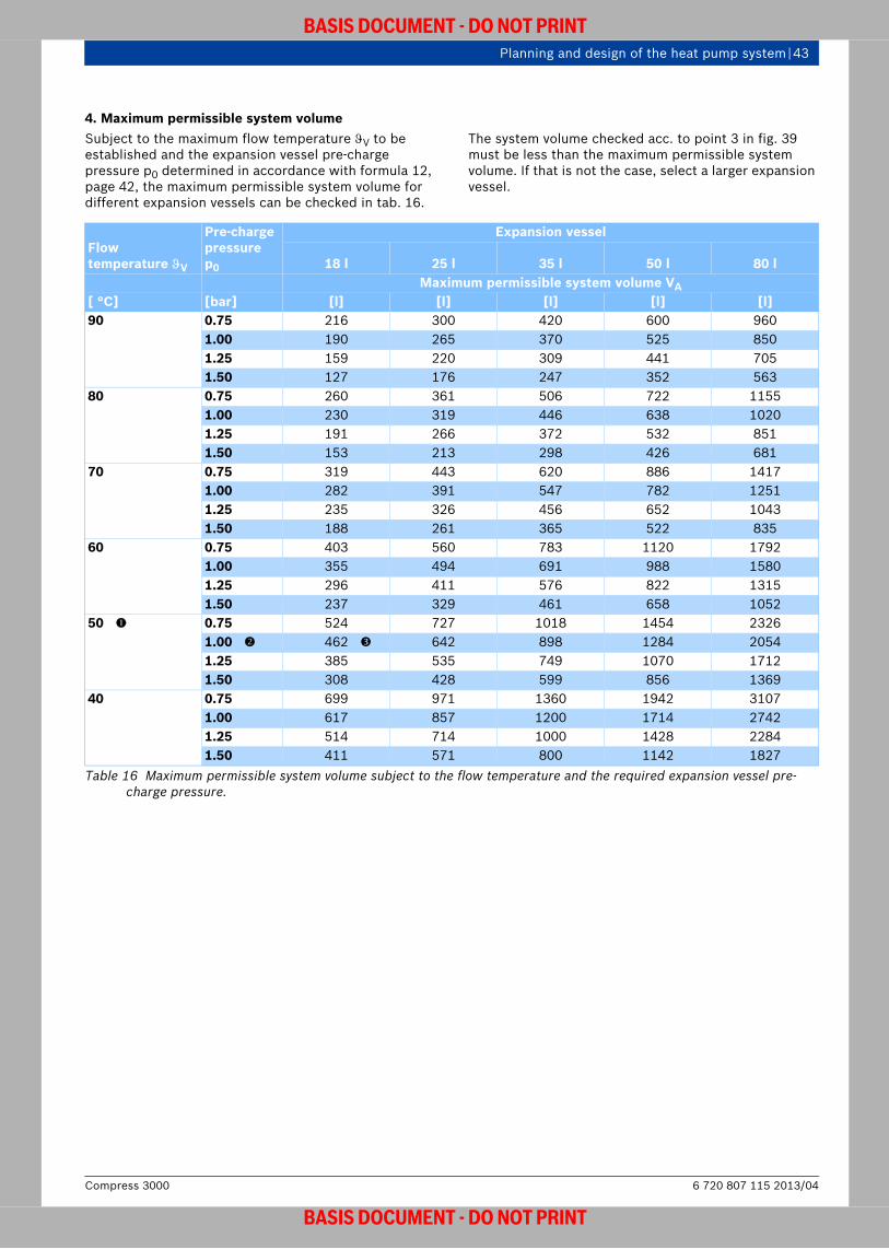
Planning and design of the heat pump system | 43
BASIS DOCUMENT - DO NOT PRINT
4. Maximum permissible system volumeSubject to the maximum flow temperature V to be established and the expansion vessel pre-charge pressure p0 determined in accordance with formula 12, page 42, the maximum permissible system volume for different expansion vessels can be checked in tab. 16.
The system volume checked acc. to point 3 in fig. 39 must be less than the maximum permissible system volume. If that is not the case, select a larger expansion vessel.
Flow temperature V
Pre-charge pressurep0
Expansion vessel
18 l 25 l 35 l 50 l 80 lMaximum permissible system volume VA
[ °C] [bar] [l] [l] [l] [l] [l]90 0.75 216 300 420 600 960
1.00 190 265 370 525 8501.25 159 220 309 441 7051.50 127 176 247 352 563
80 0.75 260 361 506 722 11551.00 230 319 446 638 10201.25 191 266 372 532 8511.50 153 213 298 426 681
70 0.75 319 443 620 886 14171.00 282 391 547 782 12511.25 235 326 456 652 10431.50 188 261 365 522 835
60 0.75 403 560 783 1120 17921.00 355 494 691 988 15801.25 296 411 576 822 13151.50 237 329 461 658 1052
50 0.75 524 727 1018 1454 23261.00 462 642 898 1284 20541.25 385 535 749 1070 17121.50 308 428 599 856 1369
40 0.75 699 971 1360 1942 31071.00 617 857 1200 1714 27421.25 514 714 1000 1428 22841.50 411 571 800 1142 1827
Table 16 Maximum permissible system volume subject to the flow temperature and the required expansion vessel pre-charge pressure.
6 720 807 115 2013/04Compress 3000
BASIS DOCUMENT - DO NOT PRINT
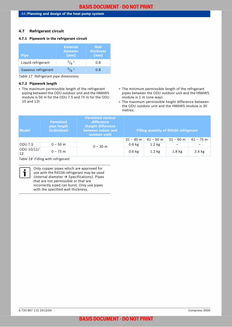
44 | Planning and design of the heat pump system
BASIS DOCUMENT - DO NOT PRINT
4.7 Refrigerant circuit
4.7.1 Pipework in the refrigerant circuit
4.7.2 Pipework length• The maximum permissible length of the refrigerant
piping between the ODU outdoor unit and the HMAWS module is 50 m for the ODU 7.5 and 75 m for the ODU 10 and 12t.
• The minimum permissible length of the refrigerant pipes between the ODU outdoor unit and the HMAWS module is 1 m (one way).
• The maximum permissible height difference between the ODU outdoor unit and the HMAWS module is 30 metres.
Pipe
External diameter
[mm]
Wall thickness
[mm]
Liquid refrigerant 3/8 " 0.8
Gaseous refrigerant 5/8 " 0.8
Table 17 Refrigerant pipe dimensions
Model
Permittedpipe length (individual)
Permitted vertical difference
(height difference between indoor and
outdoor unit)Filling quantity of R410A refrigerant
0 – 30 m
31 – 40 m 41 – 50 m 51 – 60 m 61 – 75 mODU 7.5 0 – 50 m 0.6 kg 1.2 kg – –ODU 10/11/12 0 – 75 m 0.6 kg 1.2 kg 1.8 kg 2.4 kg
Table 18 Filling with refrigerant
Only copper pipes which are approved for use with the R410A refrigerant may be used (internal diameter Specifications). Pipes that are not permissible or that are incorrectly sized can burst. Only use pipes with the specified wall thickness.
Compress 30006 720 807 115 2013/04
BASIS DOCUMENT - DO NOT PRINT

Planning and design of the heat pump system | 45
BASIS DOCUMENT - DO NOT PRINT
4.8 Heating water circuit
4.8.1 Water-side corrosion protectionCorrosion in the heating system can be caused by:• Poor water quality• Oxygen in the air entering the heating system due to
negative pressure
4.8.2 Ventilating the system and preventing the intake of oxygen
Air in the heating system reduces heat transfer at the crucial points. This can have a dramatic impact on the effectiveness of the heating system. It it therefore extremely important to ensure that there are sufficient opportunities to ventilate the system, especially in the case of properly sized heat pumps. This can be done manually or by using an automatic air vent.One of the most critical points is the amount of heating water getting in to the DHW cylinder, as this is generally very high. The following points may cause oxygen to enter the system, and should be avoided:• Leaks in the heating system• Areas of negative pressure• Expansion vessel too small• Plastic piping without oxygen barrierIf it is not possible to prevent oxygen entering the heating system (e.g. for underfloor heating systems with pipes which are permeable to oxygen), allow for system separation of the heating circuit using a heat exchanger.
4.8.3 Water quality (fill and top-up water)
Comment: VDI only valid in Germany.
Unsuitable or contaminated water can result in appliance faults and damage to the heat exchanger. Furthermore, the DHW supply can be impaired by, for example,the sludge formation, corrosion or scale build-up.To protect the heat appliance from scale damage over its entire service life and in order to ensure perfect operation, the water quality must comply with the specification in the VDI 2035 guideline.Observe the following in particular:• Only use untreated or fully desalinated tap water (note
the graph in fig. 40).• Well water and ground water are not suitable as fill
water.• Restrict the total amount of limescale-forming
substances in the fill and top-up water in the heating circuit.
To check the permitted water quantities subject to the fill water quality, consult the graph in fig. 40.
Fig. 40 Fill water requirements for single appliances up to 100 kW
[1] Water volume over the whole service life of the heat appliance (in m3)
[2] Water hardness (in °dH)[3] Untreated water in accordance with the Drinking
Water Ordinance[4] Above the limit curve, measures must be taken.
Provide system separation using a heat exchanger. Where that is impossible, check with a Bosch sales office for an approved method. The same applies to cascade systems.
The current VDI 2035 guideline “Prevention of damage in water heating installations” (issue 12/2005) aims to simplify the application and accommodate the trend towards more compact appliances with higher heat transfer rates.The graph in fig. 40 allows you to check the permissible fill and top-up water quantities for the whole service life of the heat appliance without any special measures, depending on the hardness ( dH) and the output of the heat appliance. Suitable water treatment steps are required if the water volume lies above the respective limit curve in the graph.Suitable measures are as follows:• Use of desalinated fill water with a conductivity of 10
μS/cm. No requirements are made of the pH value of the fill water.
• System separation by means of a heat exchanger; fill the primary circuit with untreated water only (no chemicals, no softening).
In order to prevent damage, the system must never be operated without water.
300
< 100 kW
< 50 kW
6 720 619 605-44.1O
6 720 807 115 2013/04Compress 3000
BASIS DOCUMENT - DO NOT PRINT
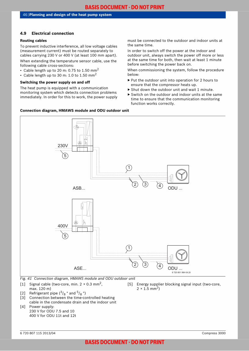
46 | Planning and design of the heat pump system
BASIS DOCUMENT - DO NOT PRINT
4.9 Electrical connection
Routing cablesTo prevent inductive interference, all low voltage cables (measurement current) must be routed separately to cables carrying 230 V or 400 V (at least 100 mm apart).When extending the temperature sensor cable, use the following cable cross-sections:• Cable length up to 20 m: 0.75 to 1.50 mm2
• Cable length up to 30 m: 1.0 to 1.50 mm2
Switching the power supply on and offThe heat pump is equipped with a communication monitoring system which detects connection problems immediately. In order for this to work, the power supply
must be connected to the outdoor and indoor units at the same time. In order to switch off the power at the indoor and outdoor unit, always switch the power off more or less at the same time for both, then wait at least 1 minute before switching the power back on.When commissioning the system, follow the procedure below:▶ Put the outdoor unit into operation for 2 hours to
ensure that the compressor heats up. ▶ Shut down the outdoor unit and wait 1 minute.▶ Switch on the outdoor and indoor units at the same
time to ensure that the communication monitoring function works correctly.
Connection diagram, HMAWS module and ODU outdoor unit
Fig. 41 Connection diagram, HMAWS module and ODU outdoor unit[1] Signal cable (two-core, min. 2 × 0.3 mm2,
max. 120 m)[2] Refrigerant pipe (3/8 " and 5/8 ")[3] Connection between the time-controlled heating
cable in the condensate drain and the indoor unit[4] Power supply:
230 V for ODU 7.5 and 10400 V for ODU 11t and 12t
[5] Energy supplier blocking signal input (two-core, 2 × 1.5 mm2)
6 720 801 984-04.2il
ASE...
ASB...
ODU ...
400V
1
2 3
ODU ...
1
2
230V
3 4
4
5
5
Compress 30006 720 807 115 2013/04
BASIS DOCUMENT - DO NOT PRINT

Planning and design of the heat pump system | 47
BASIS DOCUMENT - DO NOT PRINT
4.9.1 HMAWS .. E connection
Connection diagram, HMAWS module with electrical heating insert (HMAWS E)
Fig. 42 Connection diagram, HMAWS module with electrical heating insertContinuous line = connected at the factory; dotted line = connected during installation:[1] HMAWS module (main board)[2] Heat pump[3] Fuse (not included in standard delivery)[4] Fuse, heat pump[5] Fuse, HMAWS module[6] Accessories board[E21.B11]External input 1, energy supplier[E21.B12]External input 2[E31.RM1.TM1-5]Dew point alarm (max 5 pcs.)[E31.RM2.TM1-5]Dew point alarm for heating circuit 2
(max 5 pcs.)[E11.T1]Flow temperature sensor[E10.T2]Outside temperature sensor[E41.T3]Temperature sensor, domestic hot water[E11.TT.T5]Room temperature sensor, heating system
[E11.TT.P1]Room temperature sensor, LED[E12.TT.T5]Room temperature sensor, heating circuit 2[E12.TT.P1]Room temperature sensor, LED, heating
circuit 2[E12.T1]Flow temperature sensor, heating circuit 2[E12.B12]External input 2[E12.B11]External input 1[E31.Q11]Cooling signal output (potential-free)[E12.G1]Heating pump, heating circuit 2[E41.G6]DHW circulation pump, domestic hot water[E12.Q11]Mixing valve, heating circuit 2[E21.E112]Heating cable[E21.Q21]3-way valve (accessory)[E11.G1]Heating pump, heating system
2
3
4
6 720 648 125-26.3I
5
1
6
6 720 807 115 2013/04Compress 3000
BASIS DOCUMENT - DO NOT PRINT

48 | Planning and design of the heat pump system
BASIS DOCUMENT - DO NOT PRINT
Energy supplier connection type 1 (compressor and booster heater are disconnected)
Comment: EVU only valid for Germany and Czech republic.
Fig. 43 Control panel connection overview – ODU and EVU1 for HMAWS module with electrical heating insert[1] Control panel power supply[2] Electricity meter for heat pump, normal tariff[3] Electricity meter for the HMAWS module, low tariff[4] Tariff control, energy supplier[5] Electricity meter for the building, 1-phase normal
tariff[6] Compressor in the outdoor unit (1-phase for the
ODU 7.5 and ODU 10, 3-phase for the ODU 11t and 12t)
[7] Electrical heating insert, 9 kW[8] User interface in the HMAWS module
1 3 4 52
876
6 720 648 125-34.2I
Compress 30006 720 807 115 2013/04
BASIS DOCUMENT - DO NOT PRINT
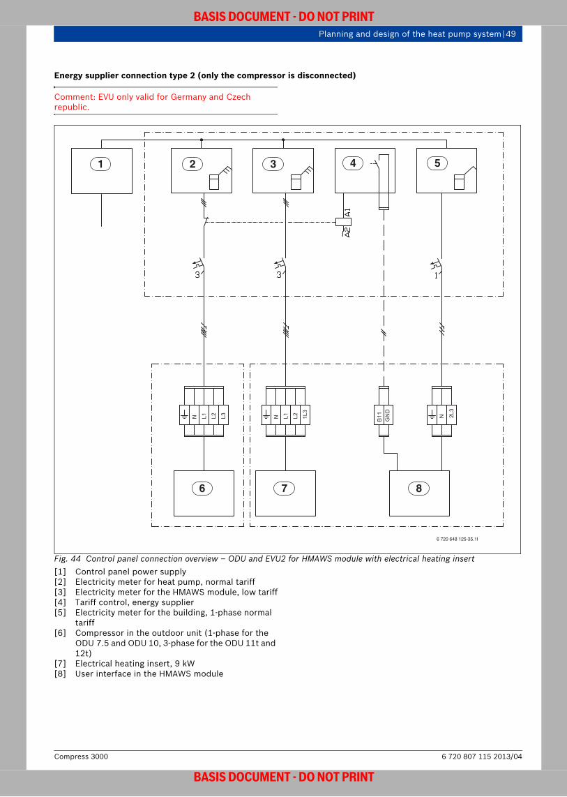
Planning and design of the heat pump system | 49
BASIS DOCUMENT - DO NOT PRINT
Energy supplier connection type 2 (only the compressor is disconnected)
Comment: EVU only valid for Germany and Czech republic.
Fig. 44 Control panel connection overview – ODU and EVU2 for HMAWS module with electrical heating insert[1] Control panel power supply[2] Electricity meter for heat pump, normal tariff[3] Electricity meter for the HMAWS module, low tariff[4] Tariff control, energy supplier[5] Electricity meter for the building, 1-phase normal
tariff[6] Compressor in the outdoor unit (1-phase for the
ODU 7.5 and ODU 10, 3-phase for the ODU 11t and 12t)
[7] Electrical heating insert, 9 kW[8] User interface in the HMAWS module
6 720 648 125-35.1I
1 3 4 52
876
6 720 807 115 2013/04Compress 3000
BASIS DOCUMENT - DO NOT PRINT

50 | Planning and design of the heat pump system
BASIS DOCUMENT - DO NOT PRINT
Energy supplier connection type 3 (only the electrical heating insert is disconnected)
Comment: EVU only valid for Germany and Czech republic.
Fig. 45 Control panel connection overview – ODU and EVU3 for HMAWS module with electrical heating insert[1] Control panel power supply[2] Electricity meter for heat pump, normal tariff[3] Electricity meter for the HMAWS module, low tariff[4] Tariff control, energy supplier[5] Electricity meter for the building, 1-phase normal
tariff[6] Compressor in the outdoor unit (1-phase for the
ODU 7.5 and ODU 10, 3-phase for the ODU 11t and 12t)
[7] Electrical heating insert, 9 kW[8] User interface in the HMAWS module
1 3 4 52
876
6 720 648 125-36.2I
Compress 30006 720 807 115 2013/04
BASIS DOCUMENT - DO NOT PRINT

Planning and design of the heat pump system | 51
BASIS DOCUMENT - DO NOT PRINT
4.9.2 HMAWS .. S connection
Connection diagram, HMAWS module with second heat appliance (HMAWS S)
Fig. 46 Connection diagram, HMAWS module with second heat applianceContinuous line = connected at the factory; dotted line = connected during installation:[1] HMAWS module (main board)[2] Heat pump[3] Fuse (not included in standard delivery)[4] Fuse, heat pump[5] Fuse, HMAWS module[6] Accessories board[E21.B11]External input 1, energy supplier[E21.B12]External input 2[E31.RM1.TM1-5]Dew point alarm (max 5 pcs.)[E31.RM2.TM1-5]Dew point alarm for heating circuit 2
(max 5 pcs.)[E11.T1]Flow temperature sensor[E10.T2]Outside temperature sensor[E41.T3]Temperature sensor, domestic hot water[E11.TT.T5]Room temperature sensor, heating system[E11.TT.P1]Room temperature sensor, LED
[E12.TT.T5]Room temperature sensor, heating circuit 2[E12.TT.P1]Room temperature sensor, LED, heating
circuit 2[E12.T1]Flow temperature sensor, heating circuit 2[E12.B12]External input 2[E12.B11]External input 1[E31.Q11]Cooling signal output (potential-free)[E12.G1]Heating pump, heating circuit 2[E41.G6]DHW circulation pump, domestic hot water[E12.Q11]Mixing valve, heating circuit 2[E21.E112]Heating cable[E71.E1.F21]Alarm signal, 2nd heat appliance (~230V)[E71.E1.E1]Start signal, second heat appliance (~230V)[E21.Q21]3-way valve (accessories)[E11.G1]Heating pump, heating system
2
3
4
6 720 648 125-25.2I
5
1
6
6 720 807 115 2013/04Compress 3000
BASIS DOCUMENT - DO NOT PRINT
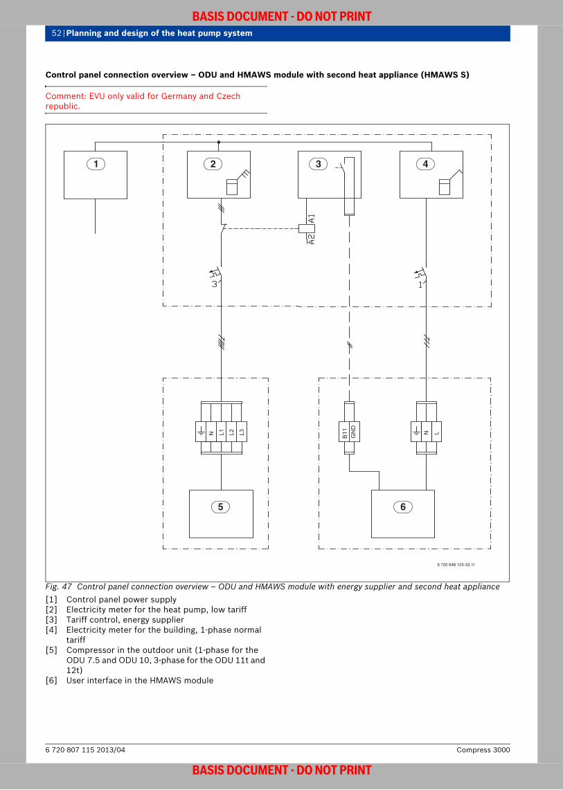
52 | Planning and design of the heat pump system
BASIS DOCUMENT - DO NOT PRINT
Control panel connection overview – ODU and HMAWS module with second heat appliance (HMAWS S)
Comment: EVU only valid for Germany and Czech republic.
Fig. 47 Control panel connection overview – ODU and HMAWS module with energy supplier and second heat appliance[1] Control panel power supply[2] Electricity meter for the heat pump, low tariff[3] Tariff control, energy supplier[4] Electricity meter for the building, 1-phase normal
tariff[5] Compressor in the outdoor unit (1-phase for the
ODU 7.5 and ODU 10, 3-phase for the ODU 11t and 12t)
[6] User interface in the HMAWS module
6 720 648 125-33.1I
1 3 4
5 6
2
Compress 30006 720 807 115 2013/04
BASIS DOCUMENT - DO NOT PRINT

Planning and design of the heat pump system | 53
BASIS DOCUMENT - DO NOT PRINT
4.10 Regulations and standards
Comment: DIN, VDE, TA Lärm only valid in Germany.
Observe the following guidelines and regulations:• DIN VDE 0730-1, issue date: 1972-03
Regulations for devices with electromotive drive for domestic use and similar purposes, part 1: General regulations
• DIN 4109Sound insulation in buildings
• DIN V 4701-10, issue date: 2003-08 (prestandard)Energy efficiency of heating and ventilation systems in buildings - Part 10: Heating, domestic hot water supply, ventilation
• DIN 8900-6, issue date: 1987-12Heat pumps. Heat pump units equipment with electrically driven compressors, methods of measurement for installed water/water, air/water and brine/water heat pumps
• DIN 8901, issue date: 2002-12Refrigerating systems and heat pumps – Protection of soil, ground and surface water – Safety and environmental requirements and testing
• DIN 8947, issue date: 1986-01Heat pumps. Heat pump units with electrically driven compressors for water heating – concepts, requirements, testing
• DIN 8960, issue date: 1998-11Refrigerants. Requirements and symbols
• DIN 32733, issue date: 1989-01Safety switching devices for pressure limiting in refrigerating plants and heat pumps – requirements and testing
• DIN 33830-1, issue date: 1988-06Heat pumps. Complete absorption pump units – concepts, requirements, testing, marking
• DIN 33830-2, issue date: 1988-06Heat pumps. Complete absorption pump units – requirements for combustible gases, tests
• DIN 33830-3, issue date: 1988-06Heat pumps. Absorption heat pump units – refrigeration safety, testing
• DIN 33830-4, issue date: 1988-06Heat pumps. Absorption heat pump units – performance and operational tests
• DIN 45635-35, issue date: 1986-04Measurement of noise emitted by machines. Airborne noise emission; enveloping surface method; heat pump units with electrically driven compressors
• EN 14511-1, issue date: 2008-02Air conditioners, liquid chilling packages and heat pumps with electrically driven compressors for space heating and cooling - Part 1: Terms and definitions
• EN 14511-2, issue date: 2008-02Air conditioners, liquid chilling packages and heat pumps with electrically driven compressors for space heating and cooling - Part 2: Test conditions
• EN 14511-3, issue date: 2008-02Air conditioners, liquid chilling packages and heat pumps with electrically driven compressors for space heating and cooling - Part 3: Test methods
• EN 14511-4, issue date: 2008-02Air conditioners, liquid chilling packages and heat pumps with electrically driven compressors for space heating and cooling - Part 4: Requirements
• EN 378-1, issue date: 2000-09Refrigerating systems and heat pumps – Safety and environmental requirements – Part 1: Basic requirements, definitions, classification and selection criteria; German version EN 378-1: 2000
• N EN 378-2, issue date 2000-09Refrigerating systems and heat pumps – Safety and environmental requirements – Part 2: Design, construction, testing, marking and documentation; German version EN 378-2: 2000
• EN 378-3, issue date 2000-09Refrigerating systems and heat pumps – Safety and environmental requirements – Part 3: Installation site and personal protection; German version EN 378-3: 2000
• EN 378-4, issue date 2000-09Refrigerating systems and heat pumps – Safety and environmental requirements – Part 4: Operation, maintenance, repair and recovery; German version EN 378-4: 2000
• EN 1736, issue date 2000-04Refrigerating systems and heat pumps – Flexible pipe elements, vibration isolators and expansion joints – Requirements, design and installation; German version EN 1736: 2000
• EN 1861, issue date 1998-07Refrigerating systems and heat pumps – System flow diagrams and piping and instrument diagrams – Layout and symbols; German version EN 1861: 1998
• EN 12178, issue date: 2004-02Refrigerating systems and heat pumps – Liquid level indicating devices – Requirements, testing and marking; German version EN 12178: 2003
• EN 12263, issue date: 1999-01Refrigerating systems and heat pumps – Safety switching devices for limiting the pressure – Requirements, tests and marking; German version EN 12263: 1998
• DIN EN 12284, issue date: 2004-01Refrigerating systems and heat pumps – Valves – Requirements, testing and marking; German version EN 12284: 2003
• EN 12828, issue date: 2003-06Heating systems in buildings – Design of water-based heating systems; German version EN 12828: 2003
• EN 12831, issue: 2003-08Heating systems in buildings – Method for calculation of the design heat load; German version EN 12831: 2003
• EN 13136, issue date: 2001-09Refrigerating systems and heat pumps – Pressure relief devices and their associated piping – Methods for calculation; German version EN 13136: 2001
6 720 807 115 2013/04Compress 3000
BASIS DOCUMENT - DO NOT PRINT

54 | Planning and design of the heat pump system
BASIS DOCUMENT - DO NOT PRINT
• EN 60335-2-40, issue date: 2004-03Household and similar electrical appliances – Safety - Part 2-40: Particular requirements for electrical heat pumps, air-conditioners and dehumidifiers
• DIN V 4759-2, issue date: 1986-05 (prestandard)Heating installations for different sources of energy; use of heat pumps including electrically operated compressors in bivalent heating installations
• DIN VDE 0100, issue date: 1973-05Erection of power installations with rated voltages below 1000 V
• DIN VDE 0700Household and similar electrical appliances – Safety
• DVGW Code of Practice W101-1, issue date: 1995-02Guidelines on drinking water protection areas; groundwater protection areas
• DVGW Code of Practice W111-1, issue date: 1997-03Planning, execution and interpretation of pumping tests in water catchment
• German Energy Savings Order, EnEV, issue date: 2009Order on energy-saving thermal insulation and systems in buildings (more detailed information page 54 ff).
• German Renewable Energies Act – EEWärmeG, issue date: 2009Act on the promotion of renewable energies in the heat sector(more detailed information page 57 ff).
• Act to promote closed cycle waste management and environmentally sustainable waste disposal, issue date: 2004-01
• ISO 13256-2, issue date: 1998-08Water-source heat pumps – Testing and rating for performance – Part 2: Water-to-water and brine-to-water heat pumps
• Regional building codes• TAB
Technical connection conditions from the relevant utility company
• TA LärmTechnical instruction for the protection against noise
• Technical rules for the Pressure Vessel Ordinance – pressure vessels
• VDI 2035 Sheet 1, issue date: 2005-12Prevention of damage in water heating installations –
Scale formation in domestic hot water supply installations and water heating installations
• VDI 2067 Sheet 1, issue date 2000-09Economic efficiency of building installations – Fundamentals and economic calculation
• VDI 2067 Sheet 4, issue date: 1982-02Economy calculation of heat-consuming installations; warm water supply
• VDI 2067 Sheet 6, issue 1989-09Economy calculation of heat-consuming installations; heat pumps
• VDI 2081 Sheet 1, issue date: 2001-07 and Sheet 2, issue date: 2003-10 (draft)Noise generation and noise reduction in air-conditioning systems
• VDI 4640 Sheet 1, issue date: 2000-12Thermal use of the underground – Definitions, fundamentals, approvals, environmental aspects
• VDI 4640 Sheet 2, issue date: 2001-09Thermal use of the underground – Ground source heat pump systems
• VDI 4640 Sheet 3, issue date: 2001-06Utilization of the subsurface for thermal purposes – Underground thermal energy storage
• VDI 4640 Sheet 4, issue date: 2002-12 (draft)Thermal use of the underground – Direct uses
• VDI 4650 Sheet 1, issue date: 2003-01 (draft)Calculation of heat pumps – Simplified method for the calculation of the seasonal performance factor of heat pumps – Electric heat pumps for space heating
• German Federal Water Act, issue date: 2002-08 Act regulating water resources
• Austria:– ÖVGW Directives G 1 and G 2 plus regional Building
Regulations– Austrian standard EN 12055, issue date: 1998-04
Liquid chilling packages and heat pumps with electrically driven compressors – Cooling mode – Definitions, testing and requirements
• Switzerland: SVGW and VKF directives, canton and local regulations, and part 2 of the LPG Directive
4.11 German Energy Savings Order (EnEV)
Comment: EnEV only valid in Germany.
4.11.1EnEV 2009 – significant changes to EnEV 2007EnEV 2007 was revised in 2009. The amendments emphasised the importance of reducing the primary energy demand for buildings and minimising transmission losses. Priority is to be given to the integration of renewable energies, e.g. by installing heat pumps.• New buildings:
– The upper limit for the permissible annual primary energy demand has been reduced by an average of 30 %.
– Electricity generated from renewable energies can be offset against the ultimate energy demand of the building (up to a maximum of the total electricity demand calculated for the house). Requirement: Electricity must be generated in the immediate vicinity of the building and must be used in the building itself first.
– The energy-related requirements for the thermal insulation of the building shell have increased by an average of 15 %.
• Modernising old buildings: If major structural changes are made to the building shell (e.g. a new façade, window or roof), element-specific requirements have become 30 % stricter on average. Alternative:
Compress 30006 720 807 115 2013/04
BASIS DOCUMENT - DO NOT PRINT

Planning and design of the heat pump system | 55
BASIS DOCUMENT - DO NOT PRINT
refurbishment where the building is reconstructed by a factor of 1.4 at the most (annual primary energy demand and thermal insulation of the building shell).
• Continuing action: Tightening requirements for the insulation of (non-accessible) top-floor ceilings (lofts). In addition to this, the ceilings of accessible top floors must be thermally insulated by the end of 2011. Roof insulation is adequate in both cases.
• Night storage heaters that are more than 30 years old are to be put out of operation and replaced by more efficient central heating systems. This applies to residential buildings containing at least six residential units and non-residential buildings with more than 500 m2 floor space. The obligation to shut down the heating systems concerned will be implemented gradually (as of 1st January 2020).Exceptions: – The buildings meet the requirements of the Thermal
Insulation Ordinance 1995 or– Replacing the system would be uneconomical or– Regulations (e.g. building plans) stipulate the use of
electrical storage heater systems. • Air conditioning systems which change the humidity of
the indoor air must be retrofitted with devices to control the humidification and dehumidification.
• Implementation measures:– Certain tests will be transferred to the flue gas
inspector.– A measure will be introduced requiring proof that
certain work has been carried out on the building stock (contractor declarations).
– Standard regulations on fines will be introduced.– Violations of certain EnEV requirements regarding
new and old buildings and the provision of false information on energy performance certificates will become administrative offences.
4.11.2Summary of EnEV 2009The EnEV makes it possible for architects, designers and building contractors to find the best energy solution for their construction project by combining the latest thermal insulation with high-efficiency systems technology. The explanations of how to optimise energy consumption, construction and system costs and operating costs are of particular interest to building contractors. Heating systems which use ambient heat prove themselves here as solutions which have a beneficial effect on construction and operating costs. Investing more in better systems technology will pay off in the long term.Heat pumps, solar thermal systems for DHW heating and ventilation systems with heat recovery prove to be particularly profitable when considered from an overall energy perspective. This is backed up by current studies from the German Ministry for Transport, Building and Housing (BMVBW) on the effectiveness of the EnEV.
Overview of the EnEV• The EnEV starts by summarising the requirements for
the energy demand of buildings. This includes the total energy consumption of a new building as well heating, ventilation and DHW heating.
• Centralised, decentralised and solar DHW heating are all taken into account.
• By calculating the amount of primary energy in the heating energy demand, we can also observe conversion losses outside the building as well as electrical auxiliary energy consumption and the use of renewable energies (heat pumps and solar thermal systems) for central heating and DHW heating.
• Compensation options are also illustrated: a high insulation standard and less efficient heating systems technology are contrasted with economical systems technology and a higher heating energy demand.
• Evidence of thermal bridges and the impermeability of the building are taken into account.
• The new energy performance certificate (energy pass) creates more market transparency for tenants, property owners and the property market.
• Conditional requirements regarding the building stock and compulsory retrofitting apply especially to old heating technologies.
• From now on, thermal insulation technology and systems technology will be of equal value. This means that systems technology and building technology have the same entitlements. As a result, opportunities for optimising energy consumption in new buildings, which have not previously been used, may be utilised to their full potential in the future.
The energy performance certificateThe EnEV states that, in future, energy performance certificates must be issued for all new buildings and, in certain cases, when major changes are made to existing buildings too.The EnEV distinguishes between an energy performance certificate and a heat performance certificate. Energy performance certificate: for new buildings and changes/extensions to existing buildings with normal room temperatures.Heat performance certificate: for buildings with low room temperatures.The energy performance certificate compiles the calculation results for new buildings:• Transmission heat loss• Expenditure factors for the heating system, DHW
heating and ventilation• Energy demand according to energy source• Annual primary energy demandIn order to create an energy performance certificate in accordance with EnEV, the annual heating energy demand must be determined according to DIN V 4108-6. The annual heat demand and the energy demand for DHW heating, which can be fixed at a flat rate, are then multiplied by a “system expenditure factor”. This must be calculated in accordance with DIN V 4701-10.
Primary energy demand as a benchmarkThe EnEV limits the transmission heat loss for a specific building. The more stringent requirement is clearly the limit placed on the amount of primary energy used for heating, DHW heating and possible ventilation.
6 720 807 115 2013/04Compress 3000
BASIS DOCUMENT - DO NOT PRINT

56 | Planning and design of the heat pump system
BASIS DOCUMENT - DO NOT PRINT
Primary energy is the reference value for the mandatory limits, which means that the following aspects must be included:• Energy losses which occur when extracting, refining,
transporting, converting or using the energy source.• Auxiliary energies required for the electrical drive of
the heating system circulation pumps.Heat pumps take the majority of the heating energy required from the environment. The heat is brought up to the temperature required by the heating system using a small amount of high-quality energy (normally electricity). If the seasonal performance factor of the heat pump is more than 2.8, this method saves a considerable amount of primary energy compared with the very energy-efficient alternative of condensing technology.
Expenditure factor, epThe system expenditure factor, ep, is the main result of the calculation described in DIN V 4701-10. It describes the ratio of primary energy used by the systems technology to the amount of useful heat it produces for central heating, ventilation and DHW heating.
ep System expenditure factorQh Heating energy demandQp Primary energy demandQtw Potable water heat demandIn accordance with the economic requirements, the expenditure factor for the systems technology should be as low as possible.
Primary energy demandThe primary energy demand is calculated using a balance method. For residential buildings with a window surface area of up to 30 %, this involves using either the simplified heating period balance method or the detailed monthly balance method according to DIN V 4108-6 in conjunction with DIN 4701-10. The monthly balance method must be used for all other building types.The EnEV provides a formula for calculating the maximum permissible primary energy demand. This formula is based on the A/V ratio: the ratio of heat-transferring surface area, A, to the gross heated volume of the building, V, (external dimensions).
ep System expenditure factorQh Heating energy demandQp Primary energy demandQtw Potable water heat demandFor a single-family home with central DHW heating where the floor space is AN = 200 m2 and A/V = 0.8, the Qp,zul would be calculated as 119.84 kWh/(m2 × a). This value, which must not be exceeded, forms the basis for the work of an architect or designer.
Compensation options between building and systemThe EnEV allows for compensation between the efficiency of the system and the thermal insulation of the building. So, for example, a house may not need to be insulated if its systems technology is improved. This is a useful option if the insulation would be very costly or could even spoil the overall appearance of the house. This allows architects and building contractors to combine aesthetics and creativity with financial aspects in order to create the perfect solution.The EnEV specifications are to be satisfied by using more efficient systems technology such as heat pumps or domestic ventilation systems with heat recovery and the maximum permissible transmission heat demand is to be observed.
Requirements for the building stockThe EnEV places demands on existing buildings. • Conditional requirements: these generally apply
when the changes made to the building element are incidental, e.g. replacements due to natural wear, removing elements which are defective or damaged, making improvements.
• Element-specific requirements: a minimum limit applies as previously. Element-specific requirements only apply when at least 20 % of the surface area of a building element in one direction is changed.
• Balance method for existing buildings – 40% rule: The 40% rule was introduced as an alternative to the element-specific requirements in order to provide more flexibility in modernisation projects. If the building exceeds the annual primary energy demand which applies for a comparable new building by a total of not more than 40 %, individual elements which are newly installed or changed are allowed to exceed the requirements given above. As is the case for new buildings, an accurate energy performance certificate must be produced for these cases.
• Mandatory retrofitting: The EnEV also contains details of mandatory retrofitting for existing buildings. Mandatory retrofitting must be carried out irrespective of any other measures taken in relation to existing building elements or systems.Heat pump technology is a particularly viable way for existing old buildings to ensure that they meet the energy-saving targets set by the EnEV and the German government. The construction expenditure is relatively low and the appliances are easy to install. The Reconstruction Loan Corporation (KfW) provides incentives for the modernisation of heating systems. The KfW CO2 building renovation program can provide funds for four different packages of measures aimed at cutting CO2 in existing residential buildings. The KfW program can be used to finance long-term climate protection investments in residential buildings, e.g. the installation of a heat pump.
ep Qp Qh Qtw+ =
Qp ep Qh Qtw+ =
Compress 30006 720 807 115 2013/04
BASIS DOCUMENT - DO NOT PRINT

Planning and design of the heat pump system | 57
BASIS DOCUMENT - DO NOT PRINT
4.12 German Renewable Energies Act (EEWärmeG)
Comment: EEWärmeG only valid in Germany.
Who does the Act apply to, and what do they have to do?The owners of newly built residential and non-residential buildings must cover a proportion of their heat demand using renewable energies. This applies to all property owners, i.e. private individuals, public or private sector, and also applies to rented properties. Any form of renewable energy can be used. If property owners do not wish to use renewable energies, they can take other climate-friendly measures, known as compensating measures: increase the amount of insulation in the building, use heat from district heating networks which are operated with renewable fuels or heat produced in combined heat and power plants (CHP).
When does the Act start to apply? The Act came into force on 1st January 2009 and all new buildings erected after this date must comply with its specifications.
Which energy sources are considered renewable in the context of the Act?The Act considers the following energy sources as renewable:• Solar radiation energy• Biomass• Geothermal energy and• Ambient heatThe Act does not consider waste heat to be a renewable energy source. However, it is still recommended as an energy source and its use is therefore recognised as a compensating measure. Everyone who owns a new building must cover a set proportion of their total heat energy demand (energy demand for heating, potable water and, where applicable, cooling, including all losses but not including auxiliary energy demand) with renewable energies, depending on the actual amount of the energy source used.
What should be noted about geothermal energy? There are two types of geothermal energy: deep geothermal energy and near-surface geothermal energy. In the case of deep geothermal energy, heat is conveyed from deep below the ground (400 m or deeper) to the Earth's surface. This generally has the advantage that the heat is at the right temperature for immediate use. In the case of near-surface geothermal energy, the heat is obtained from smaller depths and then heated to the desired temperature using a heat pump. If property owners wish to use geothermal energy to meet the renewable energy requirements, at least 50 % of their total heat energy demand must be covered in this way. Depending on the technology used, the property owner may also have to achieve certain seasonal performance factors and install a heat meter.
What should be noted about ambient heat? Ambient heat is natural heat which can be taken from the air or from water. In order to meet the renewable energy
requirements, property owners must cover at least 50 % of the total heat energy demand of their new building in this way. If ambient heat is used with the aid of a heat pump, the same technical conditions apply as for geothermal energy.
What obligations are stipulated by the Act?The owner of any building which comes under the scope of the Act must cover a proportion of the heat energy demand with renewable energies. Heat energy demand generally refers to the energy required for central heating, DHW heating and cooling.Building owners can cover a certain proportion of their heat with solar energy, for example. The Act takes into account the size of the collector. It must have an area of 0.04 m2 for each m2 of floor space heated (defined by the EnEV) if the building in question contains a maximum of two dwellings. So, for example, if the house has a living area of 100 m2, the collector must be 4 m2. In residential buildings containing three or more dwellings, a gross collector area of 0.03 m2 must be installed for each m2 of heated floor space. The following applies to all other buildings: if solar radiation energy is used, at least 15 % of the heat demand must be covered in this way. This option is also available for the owners of residential buildings.If property owners are using solid biomass, geothermal heat or ambient heat, they must cover at least 50 % of their heat demand in this way. However, the Act specifies certain ecological and technical requirements, e.g. certain seasonal performance factors if heat pumps are used. Tab. 19 shows the seasonal performance factors that must be achieved.
Are there any alternative solutions? Due to structural or other circumstances, not all owners of new buildings can use renewable energies and, in some cases, using renewable energies is not worthwhile. For this reason, the legislators have provided other measures which will also help to protect the climate. This compensating measures include:• Using waste heat• Using heat from combined heat and power plants• Connecting to a local or district heating supply
network which is partially fed by renewable energies or from combined heat and power plants
• Improved insulation in the building
Used for Heat pump SCOPCentral heating only Brine/water
Water/waterAir/water
4 4 3.5
Central heating and DHW
Brine/waterWater/water
Air/water
3.8 3.8 3.3
Table 19 Seasonal performance factor (SCOP) according to VDI 4650 Sheet 1 (2008-09)
6 720 807 115 2013/04Compress 3000
BASIS DOCUMENT - DO NOT PRINT

58 | System examples
BASIS DOCUMENT - DO NOT PRINT
5 System examples
5.1 Information regarding all system examples
System versionTo ensure reliable operation, observe the following hydraulic circuits with the matching control equipment.The following apply to all system examples:• The system layout is to be seen as a recommendation
only.• No claim to completeness is made or implied.• Observe all current regulations and guidelines/
directives concerning the system installation and component sizing on site.
List of abbreviations
Abbr. Meaning
E10.T2 Outside temperature sensor
E11.F121 Thermostat (accessories)
E11.G1 Heating pump (secondary circuit)
E11.T1 Flow temperature sensor
E11.T5 Room temperature sensor
E11.TT Room temperature sensor
E12.F121 Thermostat (accessories)
E12.G1 Heating pump (secondary circuit)
E12.T1 Flow temperature sensor
E12.TT Room temperature sensor
E12.Q11 Mixing valve
E21.Q21 3-way valve (accessories)
E31.RM1.TM1 Dew point alarm, dew point sensor 1-5
E31.RM2.TM1 Dew point alarm 2, dew point sensor 1-5
E31.Q11 Shut-off valve, cooling
E41.G6 DHW Circulation pump
E41.T3 Temperature sensor, domestic hot water
BC10 Base controller
HMC30 Control unit (integrated)
HW Low loss header
C-KO Control unit for the stove
KS01 Solar pump station
PZ DHW circulation pump
Table 20 Summary of frequently used abbreviations
R1 Solar circuit pump
R4 3-way diverter valve (between two outlets)
RTA Return temperature raising
S1 Solar collector sensor
S2 Solar cylinder temperature sensor
S5 Buffer cylinder temperature sensor
SC10/40 solar control
T 50 °C Temperature switch (on site)
SU 3-way valve
T Temperature sensor
Abbr. Meaning
Table 20 Summary of frequently used abbreviations
Compress 30006 720 807 115 2013/04
BASIS DOCUMENT - DO NOT PRINT

System examples | 59
BASIS DOCUMENT - DO NOT PRINT
5.2 System example 1: single-energy operating mode with split heat pump, separate DHW cylinder and buffer cylinder
Fig. 48 (list of abbreviations page 58)
6 720 648 131-23.3I
E31.RM1.TM1
E31.RM2.TM1
6 720 807 115 2013/04Compress 3000
BASIS DOCUMENT - DO NOT PRINT

60 | System examples
BASIS DOCUMENT - DO NOT PRINT
Heating system components
Comment: Availability of cylinders limited outside DA.
• HMAWS E split-version air to water heat pump – control unit in the indoor unit
• Electrical heating insert in the indoor unit (9 kW)• P50 W buffer cylinder (suitable for cooling) or P120 W• SH290 RW DHW cylinder• DHW diverter valve• One heating circuit without mixing-valve• One heating circuit with mixing-valve
Benefits• A separate DHW cylinder and a buffer cylinder are
incorporated between the heat pump and the consumer.
• The size of the expansion vessel must take into account the heating water volume of the buffer cylinder.
• The system is controlled via the control unit situated in the indoor unit.
• The heating circuit with a mixing-valve and the heating circuit without a mixing-valve are both supplied with heat from the buffer cylinder.
Function description When operating systems with an air heat pump in single-energy mode, heat is produced via the heat pump and – when necessary – via the electrical heating insert.The heat pump supplies heating energy to both the DHW cylinder and the buffer cylinder. If, depending on the design, the heating water needs to be reheated electrically, this is carried out by the electrical heating insert. The heating circuit with a mixing-valve and the heating circuit without a mixing-valve are both supplied with heat from the buffer cylinder.
Compress 30006 720 807 115 2013/04
BASIS DOCUMENT - DO NOT PRINT
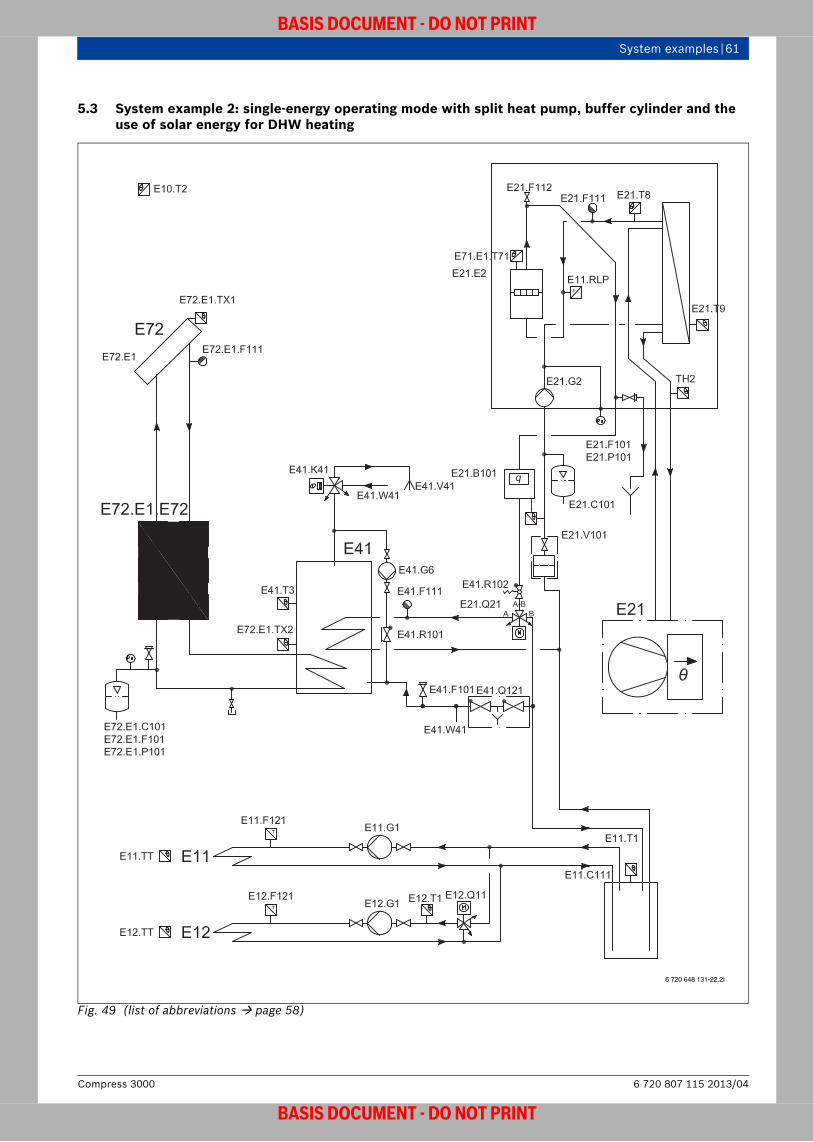
System examples | 61
BASIS DOCUMENT - DO NOT PRINT
5.3 System example 2: single-energy operating mode with split heat pump, buffer cylinder and the use of solar energy for DHW heating
Fig. 49 (list of abbreviations page 58)
6 720 648 131-22.2I
6 720 807 115 2013/04Compress 3000
BASIS DOCUMENT - DO NOT PRINT

62 | System examples
BASIS DOCUMENT - DO NOT PRINT
Heating system components
Comment: Availability of cylinders limited outside DA.
• HMAWS .. E split-version air to water heat pump – control unit in the indoor unit
• Electrical heating insert in the indoor unit (9 kW)• P50 W buffer cylinder (suitable for cooling) or P120 W• SMH400/500 E dual-energy DHW cylinder• DHW diverter valve• KS01 solar pump station• SC10 solar control• Solar collectors• One heating circuit without mixing-valve• One heating circuit with mixing-valve
Benefits• DHW is heated by a dual-energy DHW cylinder (solar
cylinder). This cylinder is supplied with heat from the connected heat pump and solar collectors.
• The heat pump is controlled via the control unit situated in the indoor unit. The solar thermal system is controlled via the solar control.
• The primary circuit heating pump supplies heat to the buffer cylinder and the upper internal indirect coil of the solar cylinder.
• The secondary circuit heating pumps supply heat from the buffer cylinder to the connected heating circuits.
Function description When operating systems with an air heat pump in single-energy mode, heat is produced for heating via the heat pump and – when necessary – via the electrical heating insert.The heat pump supplies heating energy to both the solar cylinder and the buffer cylinder. If, depending on the design, electrical reheating is required, this is carried out by the electrical heating insert. The heating circuits are supplied with heat from the buffer cylinder.
Compress 30006 720 807 115 2013/04
BASIS DOCUMENT - DO NOT PRINT
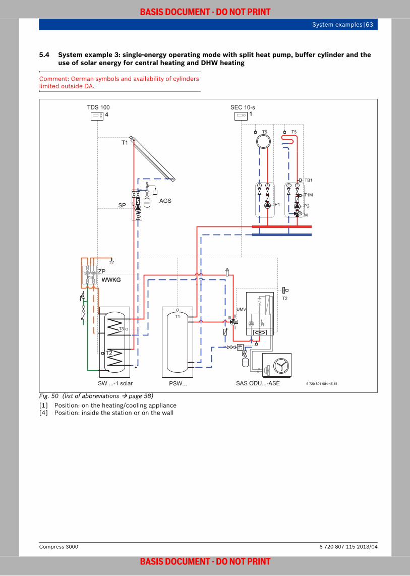
System examples | 63
BASIS DOCUMENT - DO NOT PRINT
5.4 System example 3: single-energy operating mode with split heat pump, buffer cylinder and the use of solar energy for central heating and DHW heating
Comment: German symbols and availability of cylinders limited outside DA.
Fig. 50 (list of abbreviations page 58)[1] Position: on the heating/cooling appliance[4] Position: inside the station or on the wall
AGSSP
T1
WWKG
SW ...-1 solar
WWKG
T2
T3
ZPT
4TDS 100
PSW...
T1
T T
P1
TB1
T1M
M M
T T
P2
T5 T5
1SEC 10-s
SAS ODU...-ASE
T2
M
UMV
III II
I
J
000∏
6 720 801 984-45.1il
6 720 807 115 2013/04Compress 3000
BASIS DOCUMENT - DO NOT PRINT

64 | System examples
BASIS DOCUMENT - DO NOT PRINT
Heating system components
Comment: Availability of cylinders limited outside DA.
• HMAWS .. E split-version air to water heat pump – Control unit in the indoor unit
• Electrical heating insert in the indoor unit (9 kW)• PSW buffer cylinder • SW 400/500-1 dual-energy DHW cylinder• DHW diverter valve• AGS 5 solar pump station• TDS solar control• Solar collectors• One heating circuit with mixing-valve
Benefits• The solar buffer cylinder is incorporated as a
separating cylinder between the heat pump and the consumer.
• The size of the expansion vessel must take into account the heating water volume of the buffer cylinder.
• The primary circuit heating pump supplies heat to the buffer cylinder.
• The secondary circuit heating pump supplies heat from the buffer cylinder to the connected heating circuit.
• The solar collectors support both the heating mode and the DHW heating in conjunction with the solar buffer cylinder and the dual-energy DHW cylinder (solar cylinder).
Function description When operating systems with an air heat pump in single-energy mode, heat is produced via the heat pump and – if necessary – via the integrated electrical heating insert.The solar collectors supply heat to the solar buffer cylinder and the dual-energy DHW cylinder. The DHW heating takes priority here. This ensures that the central heating and DHW heating are supported by solar energy.The dual-energy DHW cylinder supplies DHW to the connected draw-off points. In order to thermally disinfect the entire volume of the cylinder, the DHW volume must undergo a full circulation with the thermal disinfection program. The buffer cylinder takes over supplying heat to the connected heating circuit with a mixing-valve.
Compress 30006 720 807 115 2013/04
BASIS DOCUMENT - DO NOT PRINT

System examples | 65
BASIS DOCUMENT - DO NOT PRINT
5.5 System example 4: single-energy operating mode with split heat pump, buffer cylinder and the use of biomass energy for central heating and DHW heating
Comment: German symbols and availability of cylinders limited outside DA.
Fig. 51 (list of abbreviations page 58)[1] Position: on the heating/cooling appliance[5] Position: on the wall
WWKG
SW ...-1 solar
WWKG
T3
ZPT
TB1
T1M
M M1
T T
P1
T5
SEC10s
SAS ODU...-ASE
T2
M
UMV
III II
I
J
000∏
M
UMV2
I
III
II
P …S-solar
T1
T
5T 50°C C-KO
KO < 10 kW
T
FBL
T
T T
6 720 801 984-47.1il
6 720 807 115 2013/04Compress 3000
BASIS DOCUMENT - DO NOT PRINT

66 | System examples
BASIS DOCUMENT - DO NOT PRINT
Heating system components
Comment: Availability of cylinders limited outside DA.
• HMAWS E split-version air to water heat pump – Control unit in the indoor unit
• Electrical heating insert in the indoor unit (9 kW)• P500/P1000 buffer cylinder • SW400/500-1 dual-energy DHW cylinder• DHW diverter valve• Stove with back boiler• 50 °C temperature switch (on site)• Diverter valve (on site)• One heating circuit with mixing-valve
Benefits• The buffer cylinder is incorporated as a separating
cylinder between the heat pump and the consumer.• The size of the expansion vessel must take into
account the heating water volume of the buffer cylinder.
• The primary circuit heating pump supplies heat to the buffer cylinder.
• The secondary circuit heating pump supplies heat from the buffer cylinder to the connected heating circuit.
• A stove with a back boiler supports both the heating mode and the DHW heating in conjunction with the buffer cylinder and the dual-energy DHW cylinder.
Function description When operating systems with an air heat pump in single-energy mode, heat is produced via the heat pump and – if necessary – via the integrated electrical heating insert.The stove with back boiler supplies heat to the buffer cylinder and the dual-energy DHW cylinder. The heating buffer cylinder takes priority here.The dual-energy DHW cylinder supplies DHW to the connected draw-off points. In order to thermally disinfect the entire volume of the cylinder, the DHW volume must undergo a full circulation with the thermal disinfection program. The buffer cylinder takes over supplying heat to the connected heating circuit with a mixing-valve.
DANGER: Excessively high DHW temperatures may cause scalding!▶ Install a WWM thermostatic DHW mixing-
valve and set it no higher than 60 °C.
All heating circuits must be designed to include a mixing-valve.The controls must be configured to suit the system. The heating system type must be set as “radiator” on the control unit.
The on-site temperature switch with a switching point of 50 °C ensures that the maximum temperature of the heat pump return from the heating buffer cylinder is 50 °C. The on-site diverter valve, SU, serves as a switching device between the heating buffer cylinder and the DHW cylinder. At temperatures of 50 °C or more, the interaction between the temperature switch and the diverter valve ensures that only the DHW cylinder is charged.
Compress 30006 720 807 115 2013/04
BASIS DOCUMENT - DO NOT PRINT
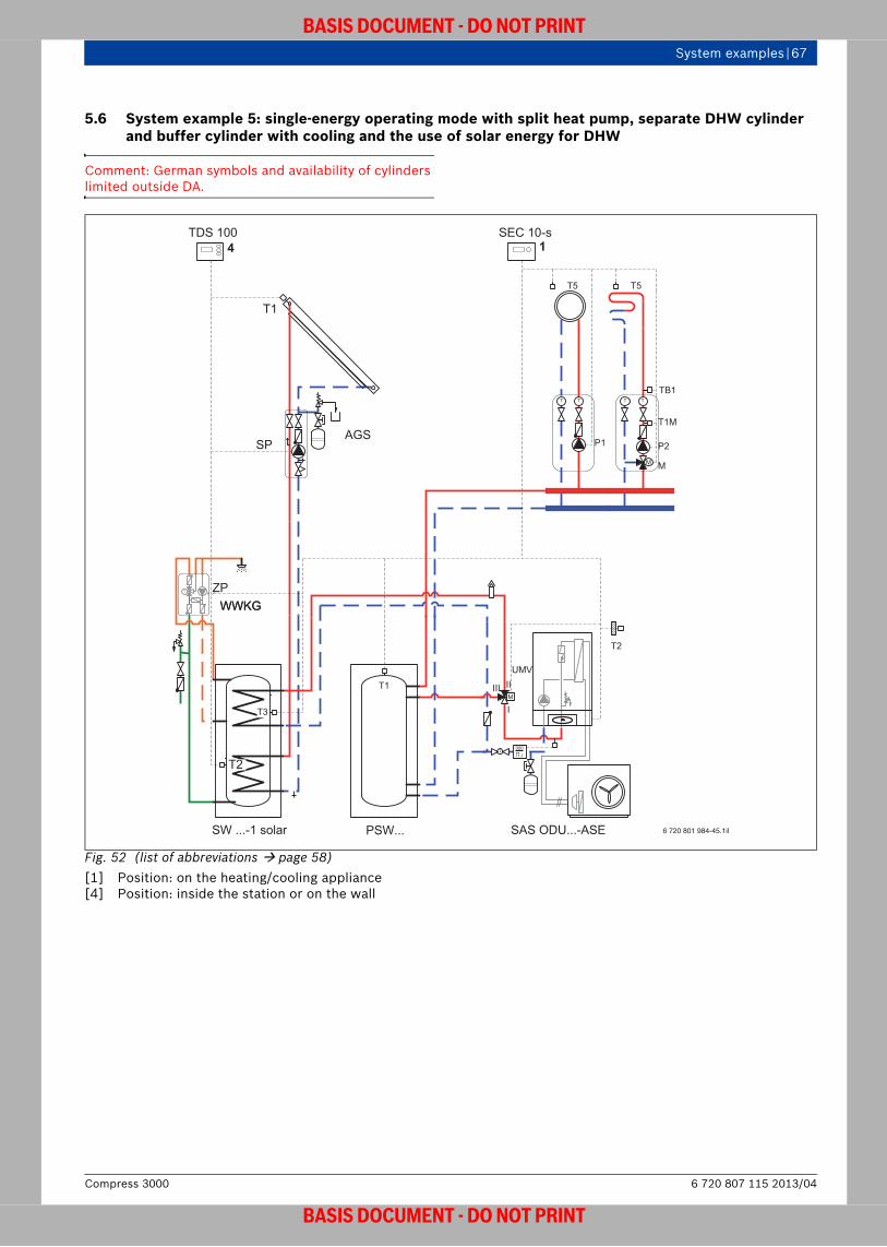
System examples | 67
BASIS DOCUMENT - DO NOT PRINT
5.6 System example 5: single-energy operating mode with split heat pump, separate DHW cylinder and buffer cylinder with cooling and the use of solar energy for DHW
Comment: German symbols and availability of cylinders limited outside DA.
Fig. 52 (list of abbreviations page 58)[1] Position: on the heating/cooling appliance[4] Position: inside the station or on the wall
AGSSP
T1
WWKG
SW ...-1 solar
WWKG
T2
T3
ZPT
4TDS 100
PSW...
T1
T T
P1
TB1
T1M
M M
T T
P2
T5 T5
1SEC 10-s
SAS ODU...-ASE
T2
M
UMV
III II
I
J
000∏
6 720 801 984-45.1il
6 720 807 115 2013/04Compress 3000
BASIS DOCUMENT - DO NOT PRINT

68 | System examples
BASIS DOCUMENT - DO NOT PRINT
Heating system components
Comment: Availability of cylinders limited outside DA.
• EWP AWS E split-version air to water heat pump – control unit in the indoor unit
• Electrical heating insert in the indoor unit (9 kW)• P50 W heating buffer cylinder• SW400/500 dual-energy DHW cylinder• DHW diverter valve• AGS 5 solar pump station• TDS 100 solar control• Solar collectors• One heating circuit without mixing-valve (fan
convector)• One heating circuit with mixing-valve (underfloor
heating)• Dew point sensor
Benefits• DHW is heated by a dual-energy DHW cylinder (solar
cylinder). This cylinder is supplied with heat from the connected heat pump and solar collectors.
• The system is controlled via the control unit situated in the indoor unit. The solar thermal system is controlled via the solar control.
• The primary circuit heating pump supplies heat to the buffer cylinder and the upper internal indirect coil of the solar cylinder.
• The heating circuit with a mixing-valve and the heating circuit without a mixing-valve are both supplied with heat or with a cooling medium from the insulated, impermeable buffer cylinder: – Fan convector for heating or cooling plus
dehumidification in summer– Underfloor heating and cooling circuits with dew
point sensors.
Function description When operating systems with an air heat pump in single-energy mode, heat is produced via the heat pump and – when necessary – via the electrical heating insert. The heat pump supplies heating energy to both the DHW cylinder and the buffer cylinder.If, depending on the design, the heating water needs to be reheated electrically, this is carried out by the electrical heating insert. The heating circuit with a mixing-valve and the heating circuit without a mixing-valve are both supplied with heat from the buffer cylinder. In summer, the heating water is cooled by the heat pump. This makes it possible to cool the room using:• Fan convector
(including dehumidification, condensate drain required)
• Underfloor heating system (no dehumidification, dew point monitoring required)Conventional heat pump buffer cylinders
(e.g. P...) are not suitable for use in systems with cooling, except for the P50 W (suitable for cooling).
Compress 30006 720 807 115 2013/04
BASIS DOCUMENT - DO NOT PRINT

System examples | 69
BASIS DOCUMENT - DO NOT PRINT
5.7 System example 6: single-energy operating mode with split heat pump, separate DHW cylinder and buffer cylinder with partial cooling
Comment: German symbols and availability of cylinders limited outside DA.
Fig. 53 (list of abbreviations page 58)[1] Position: on the heating/cooling appliance
PSWK 50
T1
T T
P1
TB1
T1M
M M
T T
P2
T5 T5
1SEC 10-s
HR...
T3
ZP
SAS ODU...-ASE
T2
M
UMV
III II
I
J
000∏
FF2
FF1
6 720 801 984-48.1il
6 720 807 115 2013/04Compress 3000
BASIS DOCUMENT - DO NOT PRINT

70 | System examples
BASIS DOCUMENT - DO NOT PRINT
Heating system components
Comment: Availability of cylinders limited outside DA.
• HMAWS .. E split-version air to water heat pump – Control unit in the indoor unit
• Electrical heating insert in the indoor unit (9 kW)• P50 W heating buffer cylinder• HR 200/300 DHW cylinder• DHW diverter valve• One heating circuit without mixing-valve
(fan convector and radiator)• One heating circuit with mixing-valve (underfloor
heating)• Dew point sensor
Benefits• A separate DHW cylinder and a buffer cylinder are
incorporated between the heat pump and the consumer.
• The size of the expansion vessel must take into account the heating water volume of the buffer cylinder.
• The system is controlled via the control unit situated in the indoor unit.
• The heating circuit with a mixing-valve and the heating circuit without a mixing-valve are both supplied with heat or with a cooling medium from the insulated, impermeable buffer cylinder: – Fan convector for heating or cooling plus
dehumidification in summer– Radiators for central heating only– Underfloor heating and cooling circuits with dew
point sensors.
Function description When operating systems with an air heat pump in single-energy mode, heat is produced via the heat pump and – when necessary – via the electrical heating insert. The heat pump supplies heating energy to both the DHW cylinder and the buffer cylinder.If, depending on the design, the heating water needs to be reheated electrically, this is carried out by the electrical heating insert. The heating circuit with a mixing-valve and the heating circuit without a mixing-valve are both supplied with heat from the buffer cylinder. In summer, the heating water is cooled by the heat pump. This makes it possible to cool the room using:• Fan convector
(including dehumidification, condensate drain required)
• Underfloor heating system (no dehumidification, dew point monitoring required)
The radiator circuit is only used for central heating and is isolated using a shut-off valve in the event of cooling.
Conventional heat pump buffer cylinders (e.g. P...) are not suitable for use in systems with cooling, except for the P50 W (suitable for cooling).
Compress 30006 720 807 115 2013/04
BASIS DOCUMENT - DO NOT PRINT
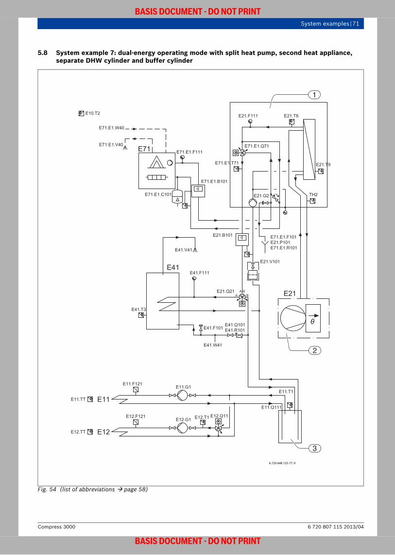
System examples | 71
BASIS DOCUMENT - DO NOT PRINT
5.8 System example 7: dual-energy operating mode with split heat pump, second heat appliance, separate DHW cylinder and buffer cylinder
Fig. 54 (list of abbreviations page 58)
3
2
1
6 720 648 125-77.1l
6 720 807 115 2013/04Compress 3000
BASIS DOCUMENT - DO NOT PRINT

72 | System examples
BASIS DOCUMENT - DO NOT PRINT
Heating system components
Comment: Availability of cylinders limited outside DA.
• EWP AWS S split-version air to water heat pump – control unit in the indoor unit
• Second heat appliance• Low loss header for second heat appliance• P50 W buffer cylinder or P120 W• HR 200/300 DHW cylinder• DHW diverter valve• One heating circuit without mixing-valve• One heating circuit with mixing-valve
Benefits• In addition to the heat pump, there is also an external
heat appliance which supports central heating and DHW heating operation in the event of peak loads.
• A separate DHW cylinder and a buffer cylinder are incorporated as separating cylinders between the heat pump and the consumer.
• The size of the expansion vessel must take into account the heating water volume of the buffer cylinder.
• The system is controlled via the control unit situated in the indoor unit.
• The heating circuit with a mixing-valve and the heating circuit without a mixing-valve are both supplied with heat from the buffer cylinder.
Function description When operating systems with an air heat pump in parallel or partially parallel dual-energy mode, heating energy is supplied to the heating circuits from a heat appliance as well as from the heat pump. The heat pump produces heat to cover the base-load output, whilst peak loads are covered by the second heat appliance, either in parallel or in alternation. The 3-way valve in the indoor unit ensures that the second heat appliance only flows through if heating water is required, and that the required heat is mixed into the heating water. A 230 V relay, which is controlled by the control unit, switches the second heat appliance on and off with the help of a potential-free relay. DHW is heated via the heat pump and, if necessary, via the second heat appliance. Systems can be installed without a low loss header if no problems are anticipated in connection with flow noises (e.g. if the output of the second heat appliance is < 1.5 times the rated output of the heat pump) or effects on the pump controls. A floor-standing boiler is fitted with a low loss header so that the boiler can fulfil the operating conditions with its own boiler controls.
Compress 30006 720 807 115 2013/04
BASIS DOCUMENT - DO NOT PRINT
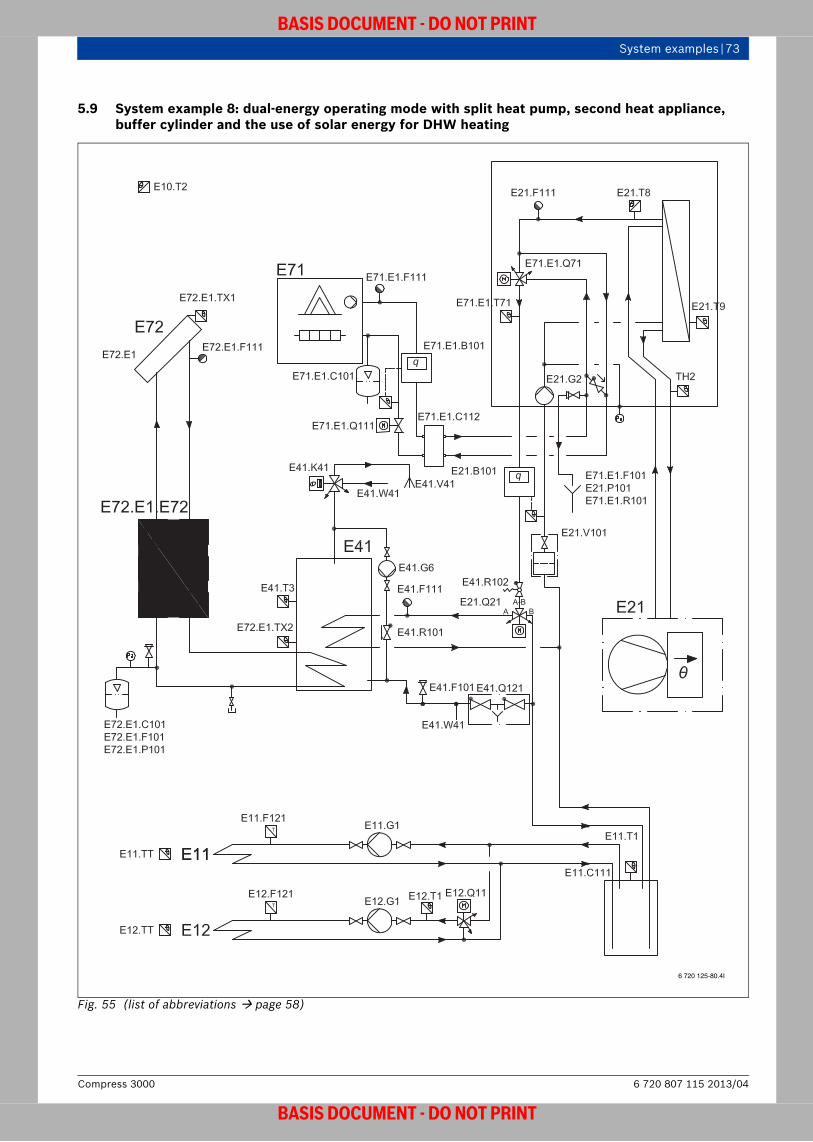
System examples | 73
BASIS DOCUMENT - DO NOT PRINT
5.9 System example 8: dual-energy operating mode with split heat pump, second heat appliance, buffer cylinder and the use of solar energy for DHW heating
Fig. 55 (list of abbreviations page 58)
6 720 125-80.4I
6 720 807 115 2013/04Compress 3000
BASIS DOCUMENT - DO NOT PRINT
74 | System examples
BASIS DOCUMENT - DO NOT PRINT
Heating system components
Comment: Availability of cylinders limited outside DA.
• EWP AWS S split-version air to water heat pump – control unit in the indoor unit
• Second heat appliance• Low loss header for second heat appliance• P50 W buffer cylinder or PSW120/200• SW400/500-1 dual-energy DHW cylinder• DHW diverter valve• AGS5 solar pump station• TDS 100 solar control• Solar collectors• One heating circuit without mixing-valve• One heating circuit with mixing-valve
Benefits• In addition to the heat pump, there is also an external
heat appliance which supports central heating and DHW heating operation in the event of peak loads. DHW is heated using a dual-energy DHW cylinder (solar cylinder). This cylinder is supplied with heat from the connected heat pump and, if necessary, from the second heat appliance and the solar collectors.
• The system is controlled via the control unit situated in the indoor unit. The solar thermal system is controlled via the solar control.
• The primary circuit heating pump supplies heat to the buffer cylinder and the upper internal indirect coil of the solar cylinder.
• The size of the expansion vessel must take into account the heating water volume of the buffer cylinder. The heating circuit with a mixing-valve and the heating circuit without a mixing-valve are both supplied with heat from the buffer cylinder.
Function description When operating systems with an air heat pump in parallel or partially parallel dual-energy mode, heating energy is supplied to the heating circuits from a heat appliance as well as from the heat pump. The heat pump produces heat to cover the base-load output, whilst peak loads are covered by the second heat appliance, either in parallel or in alternation. The 3-way valve in the indoor unit ensures that the second heat appliance only flows through if heating water is required, and that the required heat is mixed into the heating water. A 230 V relay, which is controlled by the control unit, switches the second heat appliance on and off with the help of a potential-free relay. DHW is heated via the heat pump and, if necessary, via the second heat appliance. The heat pump supplies heating energy to both the solar cylinder and the buffer cylinder.Systems can be installed without a low loss header if no problems are anticipated in connection with flow noises (e.g. if the output of the second heat appliance is < 1.5 times the rated output of the heat pump) or effects on the pump controls. A floor-standing boiler is fitted with a low loss header so that the boiler can fulfil the operating conditions with its own boiler controls.
Compress 30006 720 807 115 2013/04
BASIS DOCUMENT - DO NOT PRINT

System examples | 75
BASIS DOCUMENT - DO NOT PRINT
5.10 System example 9: dual-energy operating mode with split heat pump, second heat appliance, buffer cylinder and the use of biomass energy for central heating and DHW heating
Comment: German symbols and availability of cylinders limited outside DA.
Fig. 56 (list of abbreviations page 58)[1] Position: on the heating/cooling appliance[5] Position: on the wall
WWKG
SW ...-1 solar
WWKG
T3
ZPT
TB1
T1M
M M1
T T
P1
T5
SEC10s
M
UMV2
I
III
II
P …S-solar
T1
T
5T 50°C C-KO
KO < 10 kW
T
FBL
T
T T
1CU
HA
J
000∏
HWMV
SAS ODU...-ASB
T2
III II
I
M
UMV
J
000∏
R
6 720 801 984-53.1il
6 720 807 115 2013/04Compress 3000
BASIS DOCUMENT - DO NOT PRINT

76 | System examples
BASIS DOCUMENT - DO NOT PRINT
Heating system components
Comment: Availability of cylinders limited outside DA.
• EWP AWS S split-version air to water heat pump – control unit in the indoor unit
• Second heat appliance• Low loss header for second heat appliance• P500/P1000 buffer cylinder • SW400/500-1 dual-energy DHW cylinder• DHW diverter valve• Stove with back boiler• 50 °C temperature switch (on site)• Diverter valve (on site)• One heating circuit with mixing-valve
Benefits• The solar buffer cylinder is incorporated as a
separating cylinder between the heat pump and the consumer.
• The size of the expansion vessel must take into account the heating water volume of the buffer cylinder.
• The primary circuit heating pump supplies heat to the buffer cylinder.
• The secondary circuit heating pump supplies heat from the buffer cylinder to the connected heating circuit.
• A stove with a back boiler supports both the heating mode and the DHW heating in conjunction with the solar buffer cylinder and the dual-energy DHW cylinder (solar cylinder).
Function description When operating systems with an air heat pump in parallel or partially parallel dual-energy mode, heating energy is supplied to the heating circuits from a heat appliance as well as from the heat pump. The heat pump produces heat to cover the base-load output, whilst peak loads are covered by the second heat appliance, either in parallel or in alternation. The 3-way valve in the indoor unit ensures that the second heat appliance only flows through if heating water is required, and that the required heat is mixed into the heating water. A 230 V relay, which is controlled by the control unit, switches the second heat appliance on and off with the help of a potential-free relay. DHW is heated via the heat pump and the second heat appliance.The stove with back boiler supplies heat to the solar buffer cylinder and the dual-energy DHW cylinder. The heating buffer cylinder takes priority here. This ensures that the central heating and DHW heating are supported by solar energy.The dual-energy DHW cylinder supplies DHW to the connected draw-off points. In order to thermally disinfect the entire volume of the cylinder, the DHW volume must undergo a full circulation with the thermal disinfection program. The buffer cylinder takes over supplying heat to the connected heating circuit with a mixing-valve.
Systems can be installed without a low loss header if no problems are anticipated in connection with flow noises (e.g. if the output of the second heat appliance is < 1.5 times the rated output of the heat pump) or effects on the pump controls. A floor-standing boiler is fitted with a low loss header so that the boiler can fulfil the operating conditions with its own boiler controls.
DANGER: Excessively high DHW temperatures may cause scalding!▶ Install a WWM thermostatic DHW mixing-
valve and set it no higher than 60 °C.
All heating circuits must be designed to include a mixing-valve.The controls must be configured to suit the system. The heating system type must be set as “radiator” on the control unit.
The on-site temperature switch with a switching point of 50 °C ensures that the maximum temperature of the heat pump return from the heating buffer cylinder is 50 °C. The on-site diverter valve, SU, serves as a switching device between the heating buffer cylinder and the DHW cylinder. At temperatures of 50 °C or more, the interaction between the temperature switch and the diverter valve ensures that only the DHW cylinder is charged.
Compress 30006 720 807 115 2013/04
BASIS DOCUMENT - DO NOT PRINT
Control | 77
BASIS DOCUMENT - DO NOT PRINT
6 Control
6.1 Heating controls
6.1.1 Outside temperature sensor and room temperature sensor
If the system is to be controlled using an outside temperature sensor and a room temperature sensor, one sensor must be located on the external wall of the house and one (or two) sensors must be located centrally in the house. Only one room temperature sensor can be used per heating circuit.The room temperature sensor is connected to the heat pump and signals the current room temperature to the control. This signal influences the flow temperature. The flow temperature is reduced if the actual room temperature is higher than the selected temperature.
6.1.2 Controlling flow temperature according to demand via modulating control of heat pump compressor
The heat pump uses a variable (inverter-controlled) compressor speed which it adapts according to the heat demand. If the demand is higher or lower than the current speed, the compressor speeds up or slows down after a certain amount of time (depending on how much the speed differs from the set value), thus increasing or decreasing its output. Irrespective of how large or small the demand is, the compressor starts at the lowest set speed and speeds up in progressive stages. In its factory setting, the compressor operates at seven different speeds. If necessary, the installer can limit the number of stages. The different speeds are chosen by integration computer or by selecting “Fast acceleration” or “Fast brake”.The Integration time value is the normal control for the switching differential. The integration time determines the speed setting of the compressor if the flow temperature (T1) deviates from the heating curve by an amount less than that specified in the “Fast acceleration” or “Fast brake” menu. A factory setting of 60 degree minutes (°min) means that if the deviation is 1 °C it takes 60 minutes for the speed of the compressor to increase or decrease by 1 stage. With a deviation of 2 °C it takes 30 minutes for the speed of the compressor to change.
Fast acceleration and fast brakeThe value determines how much the flow temperature (T1) can deviate from the heating curve (in degrees) before the compressor changes speed quickly (output) without taking the integration computer into account. The factory setting is 5 °C (acceleration) and 1 °C (braking). This means that, if the flow temperature (T1) exceeds the set value of the heating curve by 1 °C, the speed is reduced by one level (braking). The speed is reduced in progressive stages as long as the deviation in the adjustable fast brake time is 1 °C or more.The opposite is true if T1 falls below the heating curve by 5 °C instead. In this case, the speed increases by one level (acceleration).
Quick stopThe quick stop value determines how much the flow temperature (T1) can exceed the heating curve (in degrees) before the compressor is switched off completely.
6.1.3 Controlling the heating pump in the indoor unitThe heating pump in the indoor unit is a high-efficiency circulation pump. The speed is controlled based on the difference in temperature between the heating circuit flow and return. The amount can be adjusted in the control. A T of 4 to 5 K is recommended for underfloor heating systems. Radiators should be operated with a T of 7 K.
6.1.4 Controlling the integrated electrical heating insert in the HMAWS .. E
The electrical heating insert in the HMAWS .. E heat pump is activated via a demand detection function in the integrated control. If the temperature remains under the set value for a long period of time, the control sends a starting signal to the electrical heating insert, which is activated once a programmable timer has elapsed. The set temperature is determined based on the heating curve and is influenced by the room temperature sensor. Every outside temperature is assigned a heating circuit flow temperature (T1) in the heating curve. This value is influenced by the room temperature sensor.If the room temperature deviates from its set temperature, the deviation is converted to a factor and added to or subtracted from the value provided in the heating curve.Other signals (such as holiday function, external input signals, etc.) can also influence the set flow temperature of the heating circuit.
6.1.5 Controlling the second heat appliance in the HMAWS .. S
When the heat pump is integrated with a second heat appliance, it is controlled using the principle of partially parallel dual-energy operation.
6 720 807 115 2013/04Compress 3000
BASIS DOCUMENT - DO NOT PRINT

78 | Control
BASIS DOCUMENT - DO NOT PRINT
This means that the heat pump covers the base-load output by itself. If necessary, the second heat appliance is connected in parallel. Beyond a definable outside temperature, the heat pump switches off and the second heat appliance covers the heat load by itself. The heat pump is designed for a flow temperature of up to 55 °C.The output from the second heat appliance is mixed in by a mixing-valve in the indoor unit. The module is controlled via a PID controller which can be adjusted as needed. E71.E1.E71 is used as the control variable.The second heat appliance is activated with an adjustable time delay as needed. Operation immediately after the second heat appliance starts up takes place in the internal circuit via a bypass valve in the indoor unit. The mixing valve opens after a similarly adjustable delay in order to prevent cold booster heater water cooling down the heating system.Heat appliances that are fitted with a flow monitoring device must be separated from the system using a solenoid valve. The HMAWS .. S is designed in such a way that it functions without a low loss header in many cases (e.g. floor-standing boilers). Due to the large number of possible combinations with external heat appliances, however, you may still need to install one. This is particularly true if the rated outputs of the heat pump and the second heat appliance differ by more than a factor of 1.5 or if the heating pump controls may have an adverse effect on one another.We recommend that you control the DHW heating from the heat pump.If DHW is heated separately in the second heat appliance, the maximum flow temperature, T1, set on the control must not be less than the heating temperature set on the boiler. This means that it is not generally possible to have a system with underfloor heating and separate DHW heating.The second heat appliance is started up using the output E71.E1.E1. This output may only be charged with an ohmic load of 150 W and must not exceed current peaks of 5 A and 3 A (starting and breaking current). Otherwise, a relay must be used for installation. This is not included in the standard delivery.The HMAWS .. S has a 230 V alarm input for the second heat appliance. If the second heat appliance features a potential-free or 0 V alarm, E71.E1.F21 must be connected with the corresponding technology (e.g. with a relay). A jumper can only short-circuit the alarm input if the second heat appliance does not have an alarm function. Under normal operating conditions, the second heat appliance may stop and start several times. If there are problems with the second heat appliance because the operating times are too short, a parallel buffer cylinder in the flow/return from the external heat appliance to the indoor unit can extend the operating time. Contact the manufacturer of the second heat appliance for further details.
If the second heat appliance is not equipped with its own heating pump, a low loss header and parallel buffer cylinder must not be used. A heating pump must be retrofitted instead.
6.1.6 Controlling two heating circuitsHeating circuit 1: The control for the first heating circuit is part of the standard equipment of the control unit and is monitored via the flow temperature sensor or in conjunction with an outside temperature sensor and a room temperature sensor (accessory).Heating circuit 2 (with a mixing-valve): The control for the second heating circuit is part of the standard equipment of the control unit, and it is also executed by the control unit. An additional room temperature sensor can be installed for heating circuit 2.In heating mode, the system temperature in circuit 1 must always be higher than in circuit 2. In cooling mode, the system temperature in circuit 1 must always be lower than in circuit 2.
Compress 30006 720 807 115 2013/04
BASIS DOCUMENT - DO NOT PRINT

Control | 79
BASIS DOCUMENT - DO NOT PRINT
6.2 Controlling the DHW heatingIn the case of the HMAWS .. S, the DHW can be heated separately (controlled by the second heat appliance) or via the heat pump control.Only the second method is recommended in connection with the associated cylinder solutions. The DHW is charged via an external 3-way valve. The control is contained in the integrated control. DHW production is monitored with the cylinder temperature sensor, T3, and the return temperature sensor in the indoor unit, T9. DHW charging starts when the temperature measured by cylinder temperature sensor T3 falls below the set T3 start temperature. DHW charging stops when the temperature exceeds the set value of T3 + 0.5 K and the set value of T9. If a greater degree of comfort is required, the T9 stop temperature can be increased to the desired temperature. However, this has a significant impact on the effectiveness of the heat pump.Separate DHW heating is only possible in the HMAWS .. S if the maximum anticipated temperature of the second heat appliance does not exceed the maximum flow temperature, T1, set on the control. The DHW circulation pump can be time-controlled in the control. You can set different settings for each day of the week.
Thermal disinfectionWhen the “Thermal disinfection” program is activated, the DHW cylinder is heated to 65 °C with the help of the heat pump and the booster heater (electrical heating insert in the HMAWS .. E and second heat appliance in the HMAWS .. S). If the temperature becomes too high for the heat pump, it is stopped and the electrical heating insert/second heat appliance increases the temperature up to the stop temperature. The thermal disinfection program is not activated in the factory setting. If this function is required, you can set the time and the interval in days under “Extended menu”. When “Activate” is selected under “Interval”, thermal disinfection is carried out once and is then deactivated again.
SOLARThe HMAWS ..E/S can be operated in conjunction with a DHW solar cylinder. The following combinations are available:• ODU 7.5 and ODU 10
with SW400 solar cylinder(only use SW 500 if you are willing to compromise DHW convenience)
• ODU 12t with SW 500 solar cylinder
6.3 External inputs on the heat pump controlThe heat pump has two external inputs, one of which can be used for signals from the energy supplier. You can choose whether the input becomes active when the contact is open or closed.
A number of settings are available, e.g.:• Temperature change:
Set how much the flow temperature is to be changed (in degrees).
• Stop heat production:Stops heat production completely, frost protection still active.
• Stop DHW charging: Select “Yes” to block the DHW heating using the heat pump.
• Booster heater only?:Select “Yes” to block the heat pump operation.
• Limit power consumption to: Select the maximum power for the booster heater. This option is used in the case of tariff control.
• Block cooling: Select “Yes” to block cooling mode.
• External blocking: Used when a fan convector is installed in the system, indicates the status of the fan.
• Thermostat: Switches the pump off and sends an alarm.
• Stop DHW booster heating: Select “Yes ”to switch off the electrical heating insert in the DHW cylinder.
• Stop radiator booster heating: Select “Yes” to stop the second heat appliance, i.e. only the compressor is used.
6 720 807 115 2013/04Compress 3000
BASIS DOCUMENT - DO NOT PRINT

80 | DHW heating and heat storage
BASIS DOCUMENT - DO NOT PRINT
7 DHW heating and heat storage
7.1 HR 200/300 DHW cylinders for heat pumps
Comment: Cylinders not available in nordic countries.
7.1.1 Equipment overviewHR ... DHW cylinders are available in 200 and 300 litre versions. Used in conjunction with Bosch heat pumps, they are the ideal way to meet individual requirements regarding the daily DHW demand.
Fig. 57 HR 200/300
Equipment level• Enamelled steel container• Protective anode against corrosion• White• Thermal insulation made from 50 mm rigid PU foam • Smooth tube heat exchanger with especially large
heating surfaces• Magnesium protective anode• thermometer
Benefits• Designed to work with Bosch split heat pumps• Two different sizes• Height-adjustable feet• Very efficient insulationSpecifications tab. 22, page 82
Function description When DHW is being drawn off, the temperature in the top of the cylinder drops by approx. 8 °C to 10 °C before the heat pump reheats the cylinder. If several short draw-off events follow each other, there can be an overshooting of the set cylinder temperature and the hot layering in the upper cylinder section. This characteristic is due to the system design.The built-in thermometer displays the prevailing temperature towards the top of the container. Due to the natural thermal stratification inside the container, the set cylinder temperature should be interpreted simply as an average value. The temperature indicator and the switching point of the cylinder temperature control are not, therefore, identical.
Only use the HR 200 and HR 300 cylinders to heat potable water.
6 720 801 984-30.1il
Compress 30006 720 807 115 2013/04
BASIS DOCUMENT - DO NOT PRINT
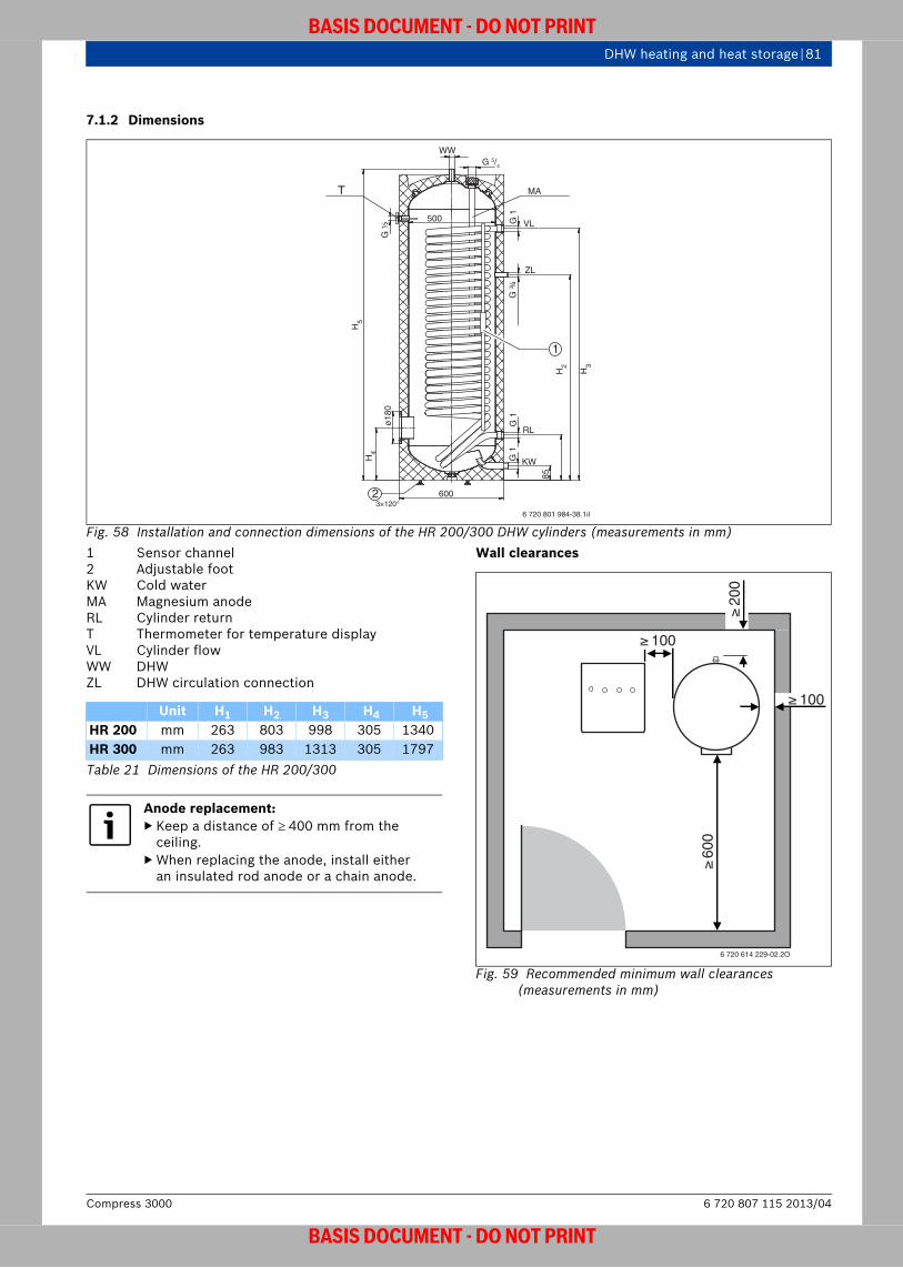
DHW heating and heat storage | 81
BASIS DOCUMENT - DO NOT PRINT
7.1.2 Dimensions
Fig. 58 Installation and connection dimensions of the HR 200/300 DHW cylinders (measurements in mm)1 Sensor channel2 Adjustable footKW Cold waterMA Magnesium anodeRL Cylinder return T Thermometer for temperature displayVL Cylinder flow WW DHWZL DHW circulation connection
Wall clearances
Fig. 59 Recommended minimum wall clearances (measurements in mm)
6 720 801 984-38.1il
WW
T
6003×120°
500
MA
VL
RL
H2
H3
H4
H5
KW
ZL
G 1
G 1
ø18
0
G 1
85
G ¾
G ½
G 5/4
1
2
Unit H1 H2 H3 H4 H5HR 200 mm 263 803 998 305 1340HR 300 mm 263 983 1313 305 1797Table 21 Dimensions of the HR 200/300
Anode replacement:▶ Keep a distance of 400 mm from the
ceiling.▶ When replacing the anode, install either
an insulated rod anode or a chain anode.
600
6 720 614 229-02.2O
100
100
200
6 720 807 115 2013/04Compress 3000
BASIS DOCUMENT - DO NOT PRINT
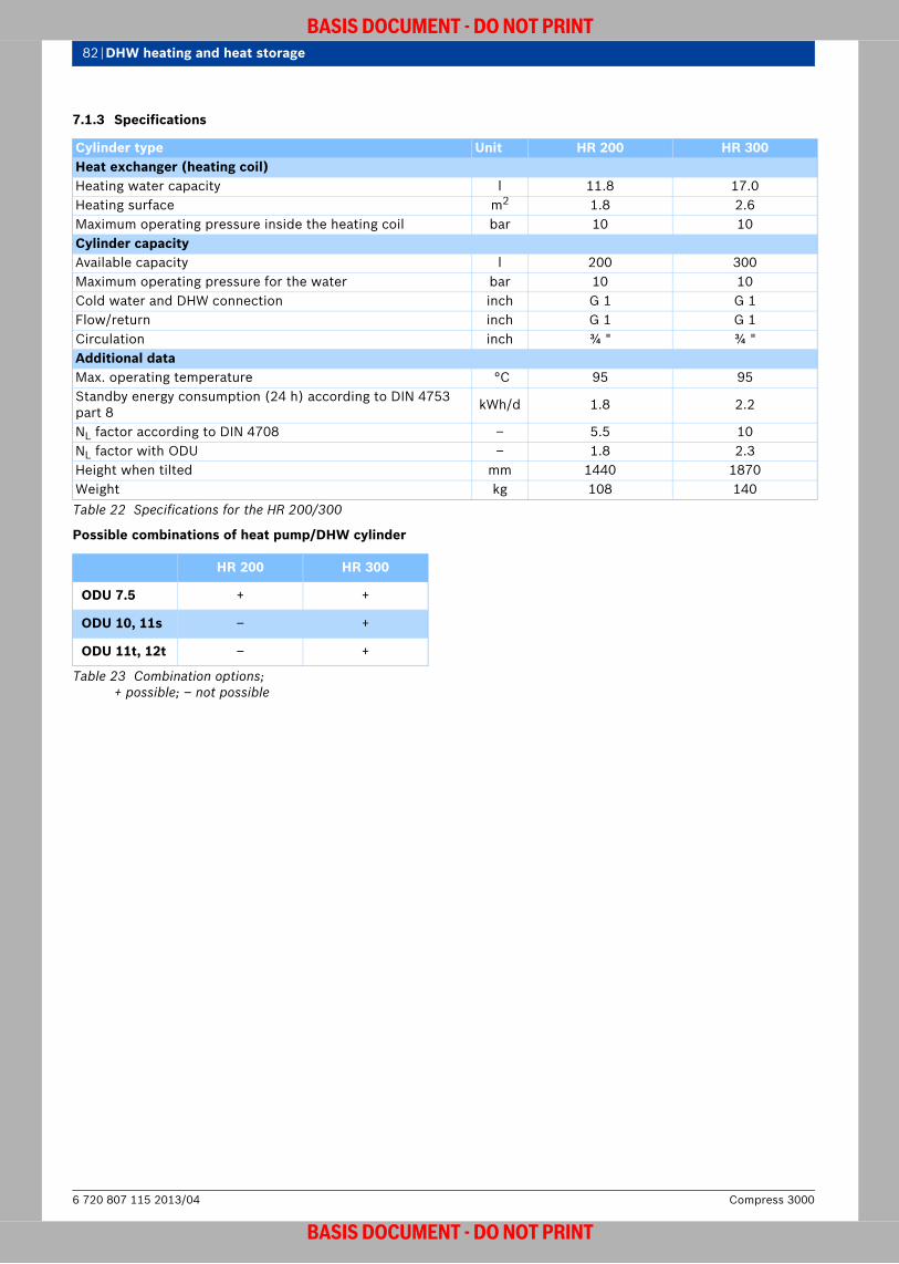
82 | DHW heating and heat storage
BASIS DOCUMENT - DO NOT PRINT
7.1.3 Specifications
Possible combinations of heat pump/DHW cylinder
Cylinder type Unit HR 200 HR 300Heat exchanger (heating coil)Heating water capacity l 11.8 17.0Heating surface m2 1.8 2.6Maximum operating pressure inside the heating coil bar 10 10Cylinder capacityAvailable capacity l 200 300Maximum operating pressure for the water bar 10 10Cold water and DHW connection inch G 1 G 1Flow/return inch G 1 G 1Circulation inch ¾ " ¾ "Additional dataMax. operating temperature °C 95 95Standby energy consumption (24 h) according to DIN 4753 part 8 kWh/d 1.8 2.2
NL factor according to DIN 4708 – 5.5 10NL factor with ODU – 1.8 2.3Height when tilted mm 1440 1870Weight kg 108 140Table 22 Specifications for the HR 200/300
HR 200 HR 300
ODU 7.5 + +
ODU 10, 11s – +
ODU 11t, 12t – +
Table 23 Combination options; + possible; – not possible
Compress 30006 720 807 115 2013/04
BASIS DOCUMENT - DO NOT PRINT

DHW heating and heat storage | 83
BASIS DOCUMENT - DO NOT PRINT
Pressure drop graphs
Fig. 60 HR 200 pressure dropp Pressure dropV Flow rate
Fig. 61 HR 300 pressure dropp Pressure dropV Flow rate
6 720 801 984-20.1il
V (m3/h)
0,1
0,5 1,5 2,5 3,0 3,5 4,0 4,52,01,00
0
0,2
0,3
0,4
0,5
0,6Δp (bar)
6 720 801 984-19.1il
V (m3/h)0,5 1,5 2,5 3,0 3,5 4,0 4,52,01,00
0,1
0
0,2
0,3
0,4
0,5
0,6Δp (bar)
6 720 807 115 2013/04Compress 3000
BASIS DOCUMENT - DO NOT PRINT
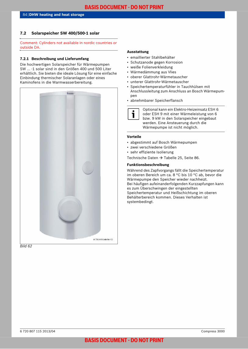
84 | DHW heating and heat storage
BASIS DOCUMENT - DO NOT PRINT
7.2 Solarspeicher SW 400/500-1 solar
Comment: Cylinders not available in nordic countries or outside DA.
7.2.1 Beschreibung und LieferumfangDie hochwertigen Solarspeicher für Wärmepumpen SW ... -1 solar sind in den Größen 400 und 500 Liter erhältlich. Sie bieten die ideale Lösung für eine einfache Einbindung thermischer Solaranlagen oder eines Kaminofens in die Warmwasserbereitung.
Bild 62
Ausstattung• emaillierter Stahlbehälter• Schutzanode gegen Korrosion• weiße Folienverkleidung• Wärmedämmung aus Vlies• oberer Glattrohr-Wärmetauscher• unterer Glattrohr-Wärmetauscher• Speichertemperaturfühler in Tauchhülsen mit
Anschlussleitung zum Anschluss an Bosch Wärmepum-pen
• abnehmbarer Speicherflansch
Vorteile• abgestimmt auf Bosch Wärmepumpen• zwei verschiedene Größen• sehr effiziente IsolierungTechnische Daten Tabelle 25, Seite 86.
Funktionsbeschreibung Während des Zapfvorgangs fällt die Speichertemperatur im oberen Bereich um ca. 8 °C bis 10 °C ab, bevor die Wärmepumpe den Speicher wieder nachheizt. Bei häufigen aufeinanderfolgenden Kurzzapfungen kann es zum Überschwingen der eingestellten Speichertemperatur und Heißschichtung im oberen Behälterbereich kommen. Dieses Verhalten ist systembedingt.
Optional kann ein Elektro-Heizeinsatz ESH 6 oder ESH 9 mit einer Wärmeleistung von 6 bzw. 9 kW in den Solarspeicher eingebaut werden. Eine Ansteuerung durch die Wärmepumpe ist nicht möglich.
Compress 30006 720 807 115 2013/04
BASIS DOCUMENT - DO NOT PRINT

DHW heating and heat storage | 85
BASIS DOCUMENT - DO NOT PRINT
7.2.2 Bau- und Anschlussmaße
Bild 63 Bau- und Anschlussmaße der Solarspeicher SW 400-1/SW 500-1 solar (Maße in mm)E Entleerung (R 1 ¼ )EH Elektro-Heizeinsatz (Zubehör)IA Inertanode (Zubehör)KW Kaltwassereintritt (R 1 ¼ )MA Magnesium-AnodeM1 Speichertemperaturfühler SolaranlageM2 Speichertemperaturfühler WärmepumpeRSP1 Speicherrücklauf Solaranlage (R 1 ¼ )RSP2 Speicherrücklauf Wärmepumpe (R 1)T Tauchhülse mit Thermometer für Temperatu-
ranzeigeVSP1 Speichervorlauf Solaranlage (R 1 ¼ )VSP2 Speichervorlauf Wärmepumpe (R 1)WW Warmwasseraustritt (R 1 ¼ )ZL Zirkulationsanschluss (R ¾ )
Wandabstandsmaße
Fig. 64 Empfohlene Mindest-Wandabstandsmaße (Maße in mm)
6 720 615 946-53.1O
EH
MA/IA
KW/E
WW
M2
M1
ZL
VSP2
VSP1
RSP2
RSP1
H
850
650
H [mm]
SW 400-1 solar 1590SW 500-1 solar 1970Tab. 24
Anodentausch:▶ Beim Tausch wahlweise eine Stabanode
oder eine Kettenanode isoliert einbauen.
6 720 618 697-11.2O
≥ 400 ≥ 100
≥ 50
0
1
6 720 807 115 2013/04Compress 3000
BASIS DOCUMENT - DO NOT PRINT

86 | DHW heating and heat storage
BASIS DOCUMENT - DO NOT PRINT
7.2.3 Technische Daten
TK Kaltwasser-EintrittstemperaturTSp SpeichertemperaturTV VorlauftemperaturTZ Warmwasser-Auslauftemperatur
Mögliche Kombinationen Wärmepumpe/Solarspeicher
Speichertyp Einheit SW 400-1 solar SW 500-1 solarWärmetauscher (Heizschlange)Inhalt Wärmetauscher Wärmepumpe (oben) l 18 27Heizfläche Wärmetauscher Wärmepumpe (oben) m2 3,3 5,1Inhalt Wärmetauscher Solaranlage (unten) l 9,5 15,5Heizfläche Wärmetauscher Solaranlage (unten) m2 1,3 1,8maximale Heizwassertemperatur °C 160 160maximaler Betriebsdruck Heizschlangen bar 16 16maximale Leistungskennzahl NL
1) nach DIN 4708 bei TV = 60 °C (maximale Speicherladeleistung)
1)Die Leistungskennzahl NL entspricht der Anzahl der voll zu versorgenden Wohnungen mit 3,5 Personen, einer Normalbadewanne und zwei weiteren Zapfstellen. NL wurde nach DIN 4708 bei TSp = 57 °C, TZ = 45 °C, TK = 10 °C und bei maximaler Heizflächenleistung ermittelt. Bei Verringerung der Speicherladeleistung und kleinerer Umlaufwassermenge wird NL entsprechend kleiner.
– 2,8 3,4
SpeicherinhaltNutzinhalt l 390 490Bereitschaftsteil l 180 250maximaler Betriebsdruck Wasser bar 10 10weitere AngabenBereitschafts-Energieverbrauch (24 h) nach DIN 4753 Teil 8 kWh/d 2,8 3,4Leergewicht (ohne Verpackung) kg 186 238Tab. 25
SW 400-1 solar SW 500-1 solar
ODU 75 + –
ODU 100 + –
ODU 120 – +
Table 26 Kombinationsmöglichkeiten; + kombinierbar; – nicht kombinierbar
Compress 30006 720 807 115 2013/04
BASIS DOCUMENT - DO NOT PRINT

DHW heating and heat storage | 87
BASIS DOCUMENT - DO NOT PRINT
7.3 Pufferspeicher PSW 120/200
7.3.1 Beschreibung und LieferumfangDer Pufferspeicher dient zur Entkopplung von Energiebereitstellung und -abnahme. Er kann die Wärmeerzeugung und den Wärmeverbrauch sowohl zeitlich als auch hydraulisch entkoppeln. Eine optimale Anpassung von Wärmeerzeugung und Wärmeverbrauch wird so möglich. Speziell bei der Wärmepumpe sichert der Pufferspeicher eine Mindestlaufzeit des Kompressors bei geschlossenen Heizungsventilen ab und erhöht dadurch die Nutzungsdauer der Wärmepumpe.Der Pufferspeicher wird als Trennspeicher zwischen Wärmepumpe und Verbraucher eingebunden. Bei der Auswahl des Pufferspeichers ist insbesondere auf eine ausreichende Wärmedämmung zu achten, so dass die Wärmeverluste nicht wieder die Vorteile der Wärmespeicherung zunichte machen.
Bild 65 PSW 120
Gerätebeschreibung• Pufferspeicher in zwei Größen mit 120 l und 200 l Fas-
sungsvermögen und mit 30 mm (PSW 120), 50 mm (PSW 200) Wärmedämmung
• Speicher aus Stahlblech in stehender zylindrischer Ausführung
• PU-Hartschaum-Isolierung direkt auf den Speicher-behälter aufgeschäumt
• Kunststoff-Abdeckung• Nicht für Anlagen geeignet, in denen Kühlung statt-
findet.
Ausstattung• Anschlüsse für Wärmeerzeuger und Heizkreise alle
seitlich abgehend• vier Rohranschlussstutzen in R ¾ bis R 2• Farbe Silber
P ... S solar
6 720 801 984-39.1il
Für Sonderanwendungen ( Anlagenbeispiel Seite 17, solare Einbindung für Heizung und Warmwasser) können auch Pufferspeicher aus der Serie P ... S solarverwendet werden.Detaillierte Beschreibungen dieser Speicher finden Sie im Bosch Katalog.
6 720 807 115 2013/04Compress 3000
BASIS DOCUMENT - DO NOT PRINT

88 | DHW heating and heat storage
BASIS DOCUMENT - DO NOT PRINT
7.3.2 Bau- und Anschlussmaße
Bild 66 Bau- und Anschlussmaße Pufferspeicher PSW 120 (Maße in mm)E EntlüftungEL EntleerungM1 Messstelle für Temperaturfühler Vorlauf (T1)M2 Messstelle für Temperaturfühler Rücklauf (GT1)R1 Rücklauf (Wärmepumpe)R2 Rücklauf (Heizsystem)V1 Vorlauf (Wärmepumpe)V2 Vorlauf (Heizsystem)
Bild 67 Bau- und Anschlussmaße Pufferspeicher PSW 200 (Maße in mm)E EntlüftungEL EntleerungM1 Messstelle für Temperaturfühler Vorlauf (T1) M2 Muffe Rp ¾ für Temperaturfühler Rücklauf (GT1)R1 Rücklauf (Wärmepumpe)R2 Rücklauf (Heizsystem)V1 Vorlauf (Wärmepumpe)V2 Vorlauf (Heizsystem)
ELEL
EV1/V2
M1R1/R2
R1(2) V1(2) V2(1) R2(1)
Ø 512
6 720 614 912-03.2O
941
15 -
25
H
D
20 -
25
E M1
M2V2
V1
R1 (M2)
R2 (EL)
6 720 801 985-10.1il
PSW 200[mm]
D (mit Wärmedämmung) 550H (mit Verkleidungsdeckel) 1445Kippmaß 1546Tab. 27
Compress 30006 720 807 115 2013/04
BASIS DOCUMENT - DO NOT PRINT

DHW heating and heat storage | 89
BASIS DOCUMENT - DO NOT PRINT
7.3.3 Technische Daten
Mögliche Kombinationen Wärmepumpe/Pufferspeicher
Wandabstandsmaße
Fig. 68 Empfohlene Mindest-Wandabstände(Maße in mm)
Pufferspeicher Einheit PSW 120 PSW 200Speicherinhalt (Heizwasser) l 120 200maximale Heizwassertemperatur °C 90Vorlauf V1, V2 Zoll R ¾ R 1Rücklauf R1, R2 Zoll R ¾ R 1Entleerung EL Zoll R ½ R 1Durchmesser Messstelle M mm 10Entlüftung E Zoll Rp 3/8maximale Heizwassertemperatur °C 90maximaler Betriebsdruck Heizwasser bar 3Leergewicht kg 60 110Tab. 28
PSW 120 PSW 200
ODU 75 + +
ODU 100 + +
ODU 120 + +
Table 29 Kombinationsmöglichkeiten; + kombinierbar; – nicht kombinierbar
6 720 807 115 2013/04Compress 3000
BASIS DOCUMENT - DO NOT PRINT

90 | DHW heating and heat storage
BASIS DOCUMENT - DO NOT PRINT
7.4 Pufferspeicher PSWK 50
7.4.1 Beschreibung und LieferumfangDer Pufferspeicher PSWK 50 ist sowohl für den Heizbetrieb als auch für den Kühlbetrieb geeignet.
Wenn die Wärmepumpenanlage auch im Kühlmodus arbeiten soll, muss der Pufferspeicher PSWK 50 eingesetzt werden.
Bild 69 PSWK 50
Mögliche Kombinationen Wärmepumpe/Pufferspeicher
6720803559-00.1Wo
PSWK 50
HMAWS...-E +
HMAWS...-S (+)1)
1)Hinweise beachten Seite 41
Table 30 Kombinationsmöglichkeiten; + kombinierbar; – nicht kombinierbar
Compress 30006 720 807 115 2013/04
BASIS DOCUMENT - DO NOT PRINT

DHW heating and heat storage | 91
BASIS DOCUMENT - DO NOT PRINT
7.4.2 Bau- und Anschlussmaße
Bild 70 Bau- und Anschlussmaße PSWK 50 (Maße in mm) EL EntleerungM1 Messstelle für VorlauftemperaturfühlerR1 Rücklauf WärmepumpeR2 Rücklauf Heizkreis(e)V1 Vorlauf WärmepumpeV2 Vorlauf Heizkreis(e)
7.4.3 Technische Daten
6 720 801 984-59.1il
Ø 530
540
Pufferspeicher Einheit PSWK 50 Speicherinhalt (Heizwasser) l 50Vorlauf V1, V2 Zoll R ¾Rücklauf R1, R2 Zoll R ¾Messstelle M1 Zoll R ½maximale Heizwassertemperatur °C 95maximaler Betriebsdruck Heizwasser bar 3Leergewicht kg 24Gesamtgewicht kg 74Tab. 31
6 720 807 115 2013/04Compress 3000
BASIS DOCUMENT - DO NOT PRINT

92 | Accessories
BASIS DOCUMENT - DO NOT PRINT
8 Accessories
Comment: All accessories are not available for all markets.
Designation Description
Room controller
• Room temperature sensor with rotary selector and LCD display
• Alarm function• Connection via CAN-BUS• Also availably with humidity sensor for indoor air
Refrigerant pipe• Connecting refrigerant pipe for split heat pump• 20 m • 3/8 " and 5/8 "
Floor supports for outdoor unit• For floor installation• With vibration dampers
Wall mounting panels for outdoor unit
• For wall mounting (for ODU 7.5 only)
Condensate collecting pan for outdoor unit
• With mesh to keep leaves away
Heating cable set• Pipe trace heating with temperature switch to
protect the condensate drain from frost• 5 m (75 W)
Bosch multi-module
• For wall mounting • Compatible with the control• Required to issue a central fault alarm, no other
functions possible with the control
DHW temperature sensor• Required in conjunction with DHW cylinder• 6 mm NTC immersion sensor• Cable length 4 m
Table 32 Accessories
Compress 30006 720 807 115 2013/04
BASIS DOCUMENT - DO NOT PRINT
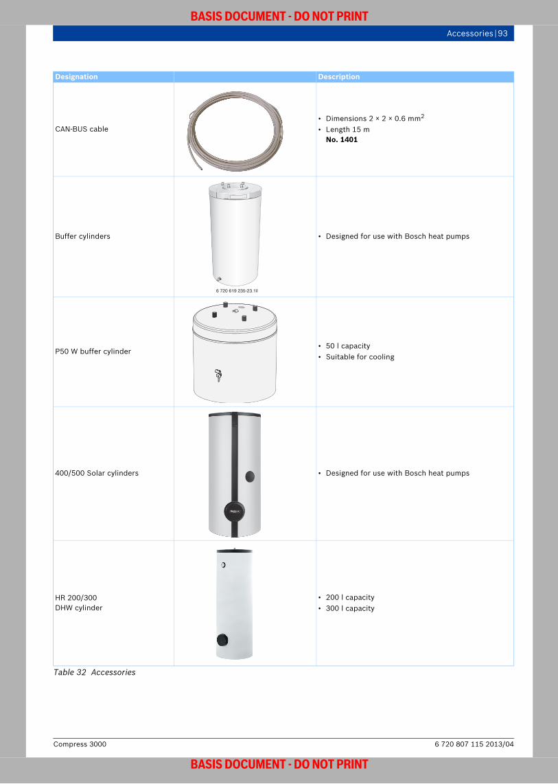
Accessories | 93
BASIS DOCUMENT - DO NOT PRINT
CAN-BUS cable• Dimensions 2 × 2 × 0.6 mm2
• Length 15 m No. 1401
Buffer cylinders • Designed for use with Bosch heat pumps
P50 W buffer cylinder• 50 l capacity• Suitable for cooling
400/500 Solar cylinders • Designed for use with Bosch heat pumps
HR 200/300DHW cylinder
• 200 l capacity • 300 l capacity
Designation Description
Table 32 Accessories
6 720 619 235-23.1il
6 720 807 115 2013/04Compress 3000
BASIS DOCUMENT - DO NOT PRINT

94 | Accessories
BASIS DOCUMENT - DO NOT PRINT
Three-way diverter valve• VZA 20, VZA 25 for switching from heating mode to
DHW mode
Dew point sensor• Al Re type TPS3, SN 120000• Includes 10 m cable• Includes 2 cable ties
Designation Description
Table 32 Accessories
6 720 619 235-170.1il
6 720 619 235-161.1il
Compress 30006 720 807 115 2013/04
BASIS DOCUMENT - DO NOT PRINT

Glossary | 95
BASIS DOCUMENT - DO NOT PRINT
Glossary Defrost managementRemoves frost and ice from evaporators in air to water heat pumps by supplying them with heat. This is carried out automatically via the control.
DefrostingIf the outside temperature drops below around +5 °C, the water contained in the air starts to settle as ice on the evaporator in the air to water heat pump. Thus, it is possible to make use of the latent heat stored in the water. Air to water heat pumps which also operate at temperatures below + 5 °C require a defrosting device. Bosch heat pumps have a defrost management function.
Startup currentThe peak current required when the appliance starts up, which only occurs for a very short period of time.
Locked-rotor current limitWhere necessary, Bosch heat pumps are fitted with smooth starters in order to limit locked-rotor current. This prevents the electric motor from starting up suddenly and violently, and ensures excellent electronic current and voltage control while the motor is starting.
Performance factorThe performance factor indicates the ratio of heat produced to the amount of electrical energy supplied. If the performance factor is considered over the period of a year, this is referred to as a seasonal performance factor (SCOP). The performance factor and the heat output of a heat pump depend on the temperature differential between heat use and heat source. The higher the temperature of the heat source and the lower the flow temperature, the higher the performance factor and, therefore, the heat output. The higher the performance factor, the lower the primary energy usage.
Outdoor installationInstalling air to water heat pumps outdoors has the advantage of making more room inside the house. It requires fewer air ducts and large openings in the walls and, because the air can flow freely, there is hardly any chance of supply air mixing with extract air. The appliances are also more easily accessible.
Outside temperature sensorThis is connected to the heat pump controller and is used for weather-compensated heating.
A/V ratioThis is the ratio of the total outer surface of a building(corresponds to its enveloping surface) to the volume that is heated. This measurement is important when calculating the energy demand of the building. The smaller the A/V ratio (compact building structure), the lower the energy demand for the same volume.
Operating voltageThe voltage required to operate an appliance, given in volts.
dual-energy switch-over temperature/dual-energy switch-over pointOutside temperature beyond which the second heat appliance is switched on in order to support the heat pump in dual-energy mode.
COPSee Coefficient of performance
Expansion valveComponent of the heat pump between the condenser and the evaporator which reduces the condensing pressure to the evaporating pressure that corresponds to the evaporating temperature. The expansion valve also controls the amount of refrigerant injected, depending on the load on the evaporator.
Panel heatingThis refers to pipework laid under the screed (underfloor heating) or wall plaster (wall panel heating), through which the heating water heated by the heat appliance flows.
Underfloor heating systemDHW underfloor heating systems are the ideal heat distribution systems for heat pump systems, because they are operated at low, energy-saving temperatures. The whole floor serves as a large heating surface. This means that these systems can manage with lower heating water temperatures (around 30 °C). As the heat is distributed evenly from the floor across the whole room, a room heated to 20 °C feels as warm as a room heated to 22 °C using a conventional system.
Building heat loadThis refers to the maximum heat load of a building. It can be calculated using DIN EN 12831. The standard heat load is calculated from the transmission heat demand (heat loss via the enveloping surfaces) and the ventilation heat demand for heating up the entering outdoor air. This value is used to size the heating system and to calculate the annual energy demand.
Base-load outputThis is the proportion of the energy output demand which is determined by considering daytime and seasonal changes with only slight fluctuations.
Heating circuitThe components of a heating system (radiator, mixing-valve, flow and return) which are hydraulically connected to one another and are responsible for distributing heat
Heat outputThe heat output of a heat pump depends on the inlet temperature of the heat source (brine/water/air) and the flow temperature in the heat distribution system. It describes the available heat output produced by the heat pump.
6 720 807 115 2013/04Compress 3000
BASIS DOCUMENT - DO NOT PRINT

96 | Glossary
BASIS DOCUMENT - DO NOT PRINT
Heating systemIn new buildings, low temperature systems can be used as heat distribution systems. Ceiling heating systems, and wall and underfloor heating systems in particular, can operate well with low flow and return temperatures. They are especially well-suited to heat pump systems, which have a maximum temperature of 55 °C.
Heating energy demandThis is the heat demand required in addition to the heat gains (solar and internal heat gains) so that a building can be kept at a desired room temperature.
Seasonal performance factorThe seasonal performance factor (SCOP) of the heat pump indicates the ratio of heating energy produced to electrical energy supplied over the period of a year. The seasonal performance factor relates to a specific system, taking into account the size of the heating system (temperature level and differential) and must not be confused with the coefficient of performance. An average temperature increase of one degree downgrades the seasonal performance factor by 2 to 2,5 %. It also increases the energy consumption by 2 to 2,5 %.
Seasonal expenditure factorThis is the inverse of the seasonal performance factor.
Cooling capacityThis describes the heat flow which is removed through the evaporator in a heat pump.
CompressorComponent of the heat pump used to mechanically convey and compress gases. Compression significantly increases the pressure and temperature of the working fluid and refrigerant.
Condensation temperatureTemperature at which the refrigerant condenses from a gaseous state to a liquid state.
Condensate panThis collects and conveys away the water that condenses on the evaporator.
Power consumptionThis refers to the amount of electrical output taken in by the appliance. It is measured in kilowatts.
Coefficient of performance (COP)The coefficient of performance is an instantaneous value. It is measured under standardised laboratory conditions according to European standard EN 14511. The coefficient of performance is a test-facility value measured without auxiliary drives. It is the quotient of the heating output and the power drawn by the compressor. The coefficient of performance is always > 1, because the heat output is always greater than the power drawn by the compressor. A coefficient of performance of 4 means that 4 times the amount of electrical output used is produced as available heat output.
Low temperature systemsLow temperature systems, especially underfloor, wall and ceiling heating systems are particularly well-suited to operation with a heat pump system.
EfficiencyThis is the quotient of the work/heat used and the work/heat expended for this purpose.
Return temperatureTemperature of the heating water which flows back from the radiators to the heat pump.
Sound insulationThis encompasses all measures which help to reduce the sound pressure level of the heat pump, e.g. sound-insulating casing lining, encapsulation of the compressors, etc. Bosch heat pumps use specially developed sound insulation and are therefore among the quietest appliances on the market.
Sound pressure level and sound power levelThe technical terms "sound pressure" and "sound power" are used to measure airborne noise:
The sound power or sound power level is a typical measure used for sources of sound. It can only be calculated from measurements taken at a defined distance from the source of the sound. It describes the total sound energy (change in air pressure) that is transmitted in all directions. If we consider the total sound power emitted and relate this to the enveloping surface at a certain distance, the value will always remain constant. The sound power level can be used to compare the acoustic properties of different appliances.The sound pressure describes the change in air pressure caused by the air starting to vibrate as a result of the noise source. The greater the change in air pressure, the louder the perceived noise. The sound pressure level measured always depends on the distance from the sound source. The sound pressure level is the technical measurement which is used to determine compliance with the immissions requirements of TA-Lärm ("Technical instruction for the protection against noise"; Germany), for example.
Safety valvesSafety valves protect pressure systems such as compressors, pressure vessels, pipework etc. from being destroyed by impermissibly high pressure levels.
Temperature differenceTemperature differential between the inlet and outlet temperature of a heat transfer medium on the heat pump, i.e. the difference between the flow and return temperatures.
Compress 30006 720 807 115 2013/04
BASIS DOCUMENT - DO NOT PRINT

Glossary | 97
BASIS DOCUMENT - DO NOT PRINT
Thermostatic valveBy restricting the heating water flow to a greater or lesser extent, the thermostatic valve adjusts the heat transfer of a radiator according to the heat demand of the room in question. Deviations from the desired room temperature can be caused by heat gains from external sources such as lighting or solar radiation. If the room temperature increases beyond the desired value due to solar radiation, the thermostatic valve will automatically reduce the heating water flow rate. On the other hand, if the temperature falls below the desired value, e.g. after ventilation, the valve will open automatically. This means that more heating water can flow through the radiator and the room temperature will return to the desired value.
Transmission heat lossesHeat losses caused by the dispersal of heat from heated rooms to the outside environment through walls, window, etc.
Reversing valveIn order to defrost the evaporator in the heat pump, the refrigerant flow direction is changed by the reversing valve. This means that the evaporator becomes the condenser during the defrosting process.
Evaporating temperatureThis is the temperature of the refrigerant when it enters the evaporator.
EvaporatorHeat exchanger in a heat pump, in which heat is extracted from the heat source (air, earth, groundwater) by evaporating a working substance at a low temperature and pressure.
CompressorComponent in a heat pump used to mechanically convey and compress gases. Compression significantly increases the pressure and temperature of the working fluid or refrigerant.
CondenserHeat exchanger in the heat pump, in which heat is transmitted to the consumer by condensing a working substance.
Fully hermeticRefers to the compressor, and signifies that it is completely closed and hermetically sealed. This means that it cannot be repaired if defective and must be replaced.
Heat demandMaximum amount of heat required to maintain a specified room or water temperature. Heat demand (central heating): Amount needed to heat rooms etc., determined according to EN 12831. Heat demand (DHW): Amount of energy or power required to heat a specified amount of potable water for showers, baths, use in the kitchen, etc.
Heat source systemA heat source system is a mechanism which extracts heat from a heat source (e.g. geothermal probes) and from the transport of the heat transfer medium between the heat source and the cold side of the heat pump, including all auxiliary equipment. In the case of air to water heat pumps, the complete heat source system is integrated in the appliance. In a single-family home, for example, the system might consist of the pipework used to distribute heat, the convectors or the underfloor heating system.
Heat transfer mediumA liquid or gaseous medium used to transport heat. This might be air or water, for example.
DHW heaterBosch offers a range of appliances for heating water. The different appliances are designed to suit the different output stages of the various heat pumps.
Water flow rateWater quantity, given in m3/h; used to determine the output of the appliances.
EfficiencyRatio of energy used to energy produced in an energy conversion process. The efficiency ratio is always less than 1 in practice, because there will always be some form of loss, e.g. waste heat.
6 720 807 115 2013/04Compress 3000
BASIS DOCUMENT - DO NOT PRINT

98 | Glossary
BASIS DOCUMENT - DO NOT PRINT
Compress 30006 720 807 115 2013/04
BASIS DOCUMENT - DO NOT PRINT