compressor model 1030 / 1031 -...
TRANSCRIPT

CompressorModel 1030 / 1031
Maintenance Manual Rev F
Taking Performance to a Higher Level

10-5501 Rev F 1
Table of Contents
Features ……………………………………………………..…….…. 2Servicing …………………………………………………………..…. 3The Air Dryer System ……………………………………………..... 4Air Intake Filter …………………………………………...………… 5Troubleshooting …………………………………………….……….. 5Computer Control System (CCS) …………………………..……… 5-6Push Button Switches………………………………….…………….. 6Led …………………………………………………………….………7-8Check Valve ……………………………………………………..……9-10Solenoid Valve ………………………………………………….……. 11Compressor Motor ………………………………………………….. 12Extended Troubleshooting …………………………………….……. 13-14Plumbing and Electrical Diagram …………………………….…….15Exploded Assembly View ………………………………….……….. 15Parts List …..……………………………..……….……. …………… 16

10-5501 Rev F 2
COMPRESSOR MODEL 1030 / 1031
Features
Model 1030:- 115 VAC at 60 Hz, 1 hp, 1200 watts, 12 amps.- Rated flow is 3.0 CFM at 100 psig.
Model 1031:- 230 VAC at 50 Hz, 2/3 hp, 1000 watts, 6 amps.- Rated flow of 2.4 CFM at 100 psig.
The following features are included with both models.- Quiet operation, noise level of approximately 53 dB at 3 feet.- Delivery of clean, dry, and oil-free air at room temperature.- Unit dimensions of 20” wide x 48” long x 25” high.- 10 gallons of air storage tank.- Delivery of pressurized air between 100 psig and 125 psig.- Computer controlled for alternating motors and demand.- A redundant system consisting of two complete systems for reliability.
Description of Compressor
The compressor is divided into four major components. The compressor motor, the air dryingsystem, the storage tanks, and the computer control system.
• The air drying system.The system consists of a dryer module and purge tank.
• The storage tank. The tank holds the pressurized air produced by the compressor. • The computer control system.
The computer control system controls and regulates the pressure that is delivered bythe compressor. This system determines when and which motor will start and stop.
• The compressor motor.This is where the air is compressed and where most of the noise is generated.
Warning: Keiser Corporation requires that the compressor be plugged directly into the walloutlet with the proper voltage and at 15 amps or greater for the 110 volt model and 10 ampsfor the 220 volt unit. The use of an extension cord can cause the unit to run irregular, ordamage the compressor, or possibly do physical harm to you.

10-5501 Rev F 3
ServicingCaution: Prior to performing any type of service to this unit, perform the following steps:Failure to follow these procedures may result in serious physical harm to you and/or damageto the unit.
Safety procedures:
1. Prior to servicing the compressor, unplug the unit from the electrical supply.
2. Slowly bleed all pressure stored in the compressor using the drain valve located onthe bottom of the tank(figure 1).
3. After bleeding all of the pressure out of the compressor, close the drain valve.
Figure 1
Tank
Inspection Port
CompressorHandle
Drain valve

10-5501 Rev F 4
The Air Drying System• The air drying system consists of a dryer module and a purge tank. The dryer module is
the smaller tank that has a black air line attached to the top. The drying module’s mainpurpose is to extract any moisture that may exist within the system and deliver drypressurized air to the main air line. The purge tank is the larger tank located next to thedryer module. The purge tank’s purpose is to dry the crystals in the dryer module canister(figure 2).
• Servicing of the dryer module is recommend when the drying module becomes sosaturated with moisture that it allows moisture to pass through it and into the main airpressure line. If this occurs, moisture will be visible in the exercise machine’s filterelement (refer to Keiser exercise machine maintenance manual) and at the tank drainwhen it is opened.
• The air dryer module is designed to be replaced without having to disassemble any of themajor components. Using a standard screwdriver, unscrew the small screw that attachesthe hose on to the top of the canister. (Figure 2).
• Twist the air dryer canister counter clockwise until it is completely loose. Pull thecanister straight up. Be careful not to damage the copper tube that travels up inside thecanister.
• Replace with a new canister, carefully sliding the copper tube up inside the bottomopening of the canister. Twist the canister clockwise hand tight and attach screw with hoseto the top of the new canister.
Copper Tube
Screw
Dryer Tank
Air Line Hose
Purge Tank
The Air Drying System Figure 2

10-5501 Rev F 5
• Air Intake Filter• The air intake filter is located on the compressor motor and filters all air entering the
system. The Keiser compressor unit was designed to operate in an environmentallycontrolled room. The servicing of this filter is dependent upon the location of thecompressor. If the compressor is located in a dirty or harsh environment, the filter mustbe checked or serviced every 6 months. We recommend replacing the filter once peryear..
• To remove the inlet filter, twist the entire filter housing off and remove it from the unit.
• Replace the filter housing with a new one. Screw it into the compressor motor hand tight.
Troubleshooting Keiser Corporation has always taken pride in designing and engineering the highest qualityequipment on the market. Only the highest quality products have the Keiser name displayed,and this compressor is no exception. In the unlikely event that any malfunctions may occur,the following section will facilitate troubleshooting and replacing any part(s) that may fail.Remember that this compressor has two computers, two air drier systems, and two motors. Ifthe right computer system indicates an error, then that error will be associated with thecomponents on the right side, likewise a left error would indicate a problem with thecomponents on the left side.
Computer Control System (CCS) Circuit Board• The computer controls system (CCS) controls and regulates the compressor’s motor. It
monitors the pressure system and aids in troubleshooting when it senses a problem. If theCCS senses an irregular condition, it will display a system error code on the LED, locatedon the circuit board. If the CCS senses a serious condition, the CCS will shut that sectionof the system down and flash an error code on the LED (figure 3). All codes areexplained in the troubleshooting section of this manual.
• The CCS keeps track of how long each motor has run since the last time the unit wasplugged in. This information is used to help insure that each motor gets equal usage underlight load conditions.
Figure 3 (Typical)
• Servicing of the CCS circuit board will become necessary in the unlikely event the boardfails to operate within the specifications set by Keiser Corporation. The CCS circuit board

10-5501 Rev F 6
is located within the box between the two compressor motors. Replacing the CCS circuitboard is the only servicing that can be done in the field.
• All terminal connections are clearly marked on the circuit board. We recommend that youlabel each wire using a pen and masking tape, as you remove them. This will help youwhen the time comes to reinstall all wiring. In the event that the labeling comes off or isnot available, follow the circuit board diagram (Table 1).
• Once all wire connections have been removed, remove the air hoses by using long nosepliers and gently pry the hose off the barb. Care must be taken as the barb can bedamaged easily. We recommend you label the air hoses.
• Remove the three screws and one nut that mount the circuit board to the box.
• Replace with new circuit board. Reinstall all fasteners.
• Prior to reinstalling the air lines, trim ¼ inch off the hose to remove any over stretch of thehose.
• Reinstall all wire connections using either Table 1 or the labels that were placed on eachwire connection.
Circuit Board Terminals Wire Source Wire ColorM1 Motor BlackV1 Solenoid Valve BlackL1 Power BlackL2 Power WhiteV2 Solenoid Valve BlackM2 Motor WhiteV3 Solenoid Valve Black
Table 1Note: Solenoid valves manufactured by “MAC” connect across V1 & V2
Solenoid valves manufactured by “Allen Air” connect across V1 & V3 on Rev K boards or later across V1 & L1 on Rev J boards or earlier
PUSH BUTTON SWITCHESThe functions of the Push Button Switches are:
Time: If this switch is pressed and held, the number of hours that this controller has appliedpower to the motor is displayed. There is no way to reset this number in the field.
Starts: If this switch is pressed and held, the number of times this controller has appliedpower to the motor is displayed. There is no way to reset this number in the field.
Both: If both switches are pressed and held, the pressure in the purge tank is displayed.
When the switches are released, the display reverts to displaying system pressure.

10-5501 Rev F 7
LEDS• The compressor has an LED that displays the pressure and also any errors it might
encounter while it is running. If you suspect a problem, look at the display to see if anerror code is displayed. Normally the display will be reading pressure by sequentiallydisplaying the pressure as one number after another. If there is an error the display willread “E r” and then a number. It will continue to repeat this error code until the errorcorrects itself or the unit is unplugged, and plugged back in to attempt to fix the error.Any time an error occurs, a small alarm will sound to alert someone of the condition. Thealarm does not sound on errors that can retry and recover. The following is a list of errorcodes and their meaning:
E r 1 - The computer thinks that the check valve is leaking. The computer detects thiscondition by watching the pressure drop in the purge tank. Once the purge tankpressure has fallen to about 5 psig, the computer tests the pressure in the main tank. Ifit has also fallen to a low value, this error condition is set. A very likely cause of thiscondition is a leaking check valve.
E r 2, E r 8 - The unit is running for an extended period of time without reaching theshut off pressure. These errors are given when the unit runs for over an hour andpressure is not reaching the shut off setting (approximately 120 psi). The unit will stillshut off every 5 minutes to allow itself to purge the dryer assembly, even if it does notreach the shut off pressure and it will display E r 8. If, after 20 cycles, the unit fails toreach the shut off pressure, the compressor will shut down and not restart, displayingE r 2. This condition means there must be a leak within the system or the compressoris not pumping properly. Shut off the valve supplying air to the main airline, and resetthe compressor by unplugging it for a few seconds. Run the compressor and note if thecompressor builds up pressure and shuts off. A view hole on top of the circuit boxhousing assembly will allow you to see at what pressure the compressor shuts off. Ifthe compressor builds up pressure and shuts off, the leak is in one of the exercisemachines or an air supply line leading to them. If the compressor does not buildpressure, then the problem is in the compressor. In this case inspect the compressorfor any leaks. If the compressor is not the problem then the machines should beunplugged and the valve opened to fill the air line. The machines should be pluggedin one at a time to see which one has the leak.
E r 3, E r 4, E r 5 - Purge tank pressure did not drop as quickly as it should. Thepurge tank must bleed air through the dryer to regenerate it. This must happen beforethe compressor can restart. If this takes too long, then this error will be displayed.Probable cause is the solenoid valve or dryer module is plugged. Anything thatrestricts the air from exiting the purge tank through the drier and then to the solenoidvalve can cause this error.
E r 6 - Computer thinks the motor did not start. The motor was given a signal to startbut pressure in the purge tank did not build up as fast as it should have. The motor orstart circuit could be faulty. Drain the air, plug the unit in and listen for thecompressor to attempt to start and see if the motor tries to start or the solenoid valvecloses. If the motor does not start and the solenoid valve clicks, then the motor isfaulty and must be replaced. If the solenoid valve does not click and the motor doesnot start, then the computer board must be replaced. It is best to use a voltmeter toinsure that the computer is sending voltage to the motor. Contact Keiser Service forassistance. If the motor runs, then check plumbing to insure that all hoses areconnected.

10-5501 Rev F 8
E r 7 - Compressor stopped because pressure did not rise quickly enough in storagetanks. A large leak probably exists in one of the exercise machines or in thecompressor plumbing or the air distribution system.
E r 9 – The computer thinks that the intake muffler is plugged. It detects thiscondition by testing the rate of pressure increase in the drier when the compressor firststarts.
E r A The computer is not able to communicate with the other computer. Thecommunications cable is damaged or the computer itself has a defect. Check thecondition of the cable. Either computer could cause itself or the other to display thiserror.

10-5501 Rev F 9
Check Valve
• A check valve is installed between the purge tank and the main air pressure in the storagetank. This check valve allows the purging of the drying module and the purge tank whilemaintaining system pressure in the main tank (figure 4).
• When the compressor shuts off, the solenoid valve bleeds off the pressure in the driermodule. This should take less than 1 minute. If air continues to bleed from the driersponge for more than 1 minute, the most likely problem is the check valve. This may beconfirmed by an error code “E r 1” on the Computer control system (CCS) circuit board(Refer to the CCS section on page 7-8). If the check valve is leaking, it will allow airfrom the main storage tank to leak into the air drier module and out to the atmosphere.The computer will shut this side of the compressor down, but the leak will continue. Theother side of the compressor will continue to run trying to replenish the air that is leaking.If this occurs, the manual valve on the solenoid, which is located on the side of thecompressor that is leaking, can be closed to enable the compressor to build pressure. Theleaking check valve should then be replaced. Once the check valve is replaced, themanual valve must be reopened.
• The check valve is mounted on the main tank under the drier assemblies on the backsidenear the center (figure 4).
Check Valve
End Cap
Street Tee
Air Hose
Male Portion
Barb withOrifice
Female Portion
Hex nipple
Figure 4
Caution: Follow all safety procedures prescribed earlier
10-5501 Rev F 10
• To remove the check valve, label the “Top hose” and “Bottom Hose” and remove the airhoses that are connected to the end cap. Be careful not to damage the barbs whenremoving hoses. When unscrewing the end cap, a wrench must be placed on the maleportion of the check valve to keep it from rotating (figure 4).
• To unscrew the check valve, place a wrench on the female portion of the valve and rotateit (figure 4). You may need to hold the hex nipple on one side to prevent it fromloosening.
• To install the new check valve, clean threads on the male part of the tee. Apply a small
amount of Locktite ® 242 on the threads. Install the check valve, place the wrench on thefemale portion of the valve and rotate (figure 4).
• Apply a small amount of Locktite ® 242 to the threads on the check valve. Place a wrenchon the male portion of the valve, hold the valve and screw on the end cap.
Note: The end cap has two barbs that are attached to it. One of the barbs contains asmall plastic orifice. Make sure the barb with the small orifice ends upon top while the other barb is directly underneath it.
• Trim ¼ inch off the air hoses to eliminate the over stretch and reinstall the air hoses to theend cap being careful to attach them to the correct barb.

10-5501 Rev F 11
• Solenoid Valve
• The solenoid valves allow purge air to pass through the air drier canisters. These valvesare mounted on the bracket that holds the drier assembly.
• The solenoid valves are also equipped with a shut-off valve installed on the solenoid itself.
In the event one of the check valves fail, the manual shut-off valve can be used to stop theleak created by the leaking check valve. The other half of the compressor will continueworking until the bad check valve can be replaced.
• To remove the solenoid valve, remove the wires going from the valve to the computer.
Review and make note which terminals the wires go to. Remove the wires from thecircuit board by holding the electrical terminals and pulling straight up.
Figure 5• Using a pair of needle nose pliers, place the jaws on either side of the air hose, and gently
pry the hose off the barb that is mounted to the valve. Take care not to damage the barbs(figure 5).
• Install the new valve and tighten the mounting screws. • Check the ends of the air hoses for any cracks or over stretching. Always trim ¼ inch off
the ends of the air hoses where they have stretched. When reinstalling the air hoses, pushthe edge of the hose onto the last ridge of each barb.
• Reconnect the wire terminals to their corresponding locations on the circuit board.
“Allen Air” valve shown
10-5501 Rev F 12
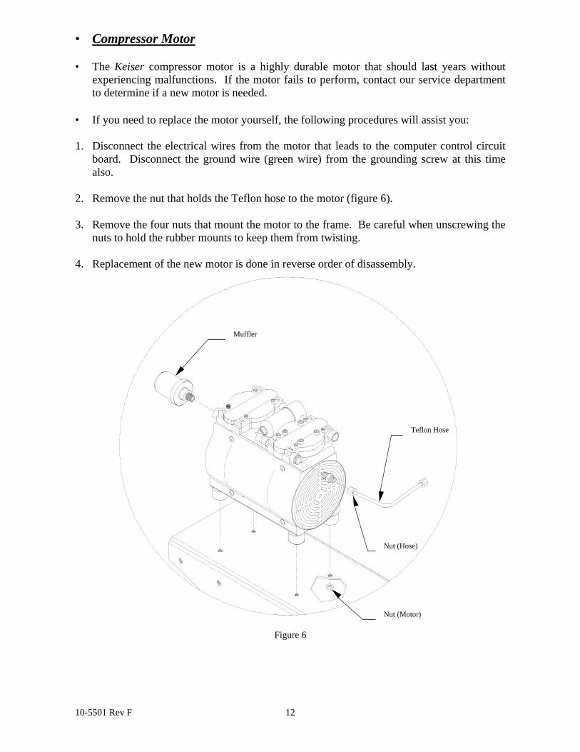
• Compressor Motor
• The Keiser compressor motor is a highly durable motor that should last years withoutexperiencing malfunctions. If the motor fails to perform, contact our service departmentto determine if a new motor is needed.
• If you need to replace the motor yourself, the following procedures will assist you: 1. Disconnect the electrical wires from the motor that leads to the computer control circuit
board. Disconnect the ground wire (green wire) from the grounding screw at this timealso.
2. Remove the nut that holds the Teflon hose to the motor (figure 6). 3. Remove the four nuts that mount the motor to the frame. Be careful when unscrewing the
nuts to hold the rubber mounts to keep them from twisting. 4. Replacement of the new motor is done in reverse order of disassembly.
Figure 6
Muffler
Teflon Hose
Nut (Motor)
Nut (Hose)
10-5501 Rev F 13
Extended Troubleshooting
Use this procedure to determine if your Keiser air compressor is performing correctly.
1. Unplug the compressor. Next drain the tank by opening the drain petcock at the bottom ofthe tank. Close the petcock when the tank is completely drained. The output valve (valvethat allows air to the exercise machines) should be closed for the duration of this entiretest.
2. Close the drain valve and plug the compressor in. Start timing with a stopwatch when themotors start. Both motors should start at about the same time, several seconds afterplugging the unit in. If they do not, locate and repair the cause of this problem beforeproceeding. If a solenoid valve clicks (several seconds after plugging the unit in) and itsmotor does not start, the motor is defective. If a motor starts immediately, there is aproblem with the electronic controller and it must be replaced.
3. Record the time it takes for the motors to stop. The total time should be about 4 minutesat sea level. This is the empty pump up time. See table 2 for times at other elevations.The pressure should display 117 – 124 PSIG at this time. The pressure readings should bewithin 4 PSI from one side to the other.
4. Verify that the unit is holding steady pressure (not leaking). Pressure could drop 1 to 2PSI in the first minute due to thermal effects but should not drop after that. Leave it sit forat least 2 minutes. After setting for over a minute, the air bleeding from the drain spongeshould stop. If there is still air coming out of either sponge chamber after 2 minutes. Acheck valve is leaking or a solenoid valve is partially plugged.
5. Unplug the unit for a few seconds then plug it back in. Next lower the pressure at a rate ofapproximately 1 PSI per cycle of the display until the compressors both start. Start timingwhen the compressors start.
6. Let the compressors run until they just stop. Record the time to the stop and start timingagain. The time you just recorded is the run time, and the time you are just starting is thebleed time. If you do not have a split time or dual stop watch, you may have to repeat theprocedure and time run time and bleed time separately on two passes.
7. Very quickly drop the pressure in the system to about 90 PSIG by using the tank drainvalve.
8. Stop timing when the compressors start again. This is the bleed down time. It should beabout 45 seconds. If this time is much longer than it should be, suspect a pluggedsolenoid valve or hoses running to and from it. Make a note to observe that the differencein time from the first compressor stopping until the second compressor stops is about thesame as the time from the first compressor to start until the final compressor starts.
9. If the run time is too long, try running the test with the intake mufflers removed. If thetime is still too long, run the test on each compressor separately to determine whichcompressor is the cause of the problem.
10. To run the same test on one compressor at a time, lower the pressure slowly, then whenthe motor starts; stop the leak. Repeat for the other motor. If the same motor starts eachtime you can disconnect the wires to the motor on the side you do not want to test.

10-5501 Rev F 14
11. Approximate times at various altitudes.
Sea Level 4000 Feet 7000 Feet
Fill Time 4 minutes 4 MN 45 SEC 5 MN 20 SEC
Bleed Time 45 seconds 50 seconds 47 seconds
Run Time (BOTH) 1 MN 20 SEC 1 MN 30 SEC
Run Time (ONE) 1 MN 55 SEC 2 MN 10 SEC
Table 2
The effects of some common failures are as follows.
Check Valve Leaking. On the air compressor when a check valve leaks on one side, thesystem will build to full pressure from a cold start (unit plugged in with no pressure in thetank). When the compressor motors stop the solenoid valves will open allowing air to drainfrom the drier through the sponge. Since a check valve is bad, there will be constant aircoming from the sponge on the bad side. The compressor on the other side will start when thesystem pressure drops back to the start pressure and air will continue leaking from the spongeon the bad side. Eventually the good side will time out after several cycles through Er8 andstop at Er2. The bad side will have stopped at Er5 or Er3 while this is happening. Once thegood side times out and stops completely, the pressure will drop almost all the way to 0 andthe bad compressor will start up again. The clue that will help find the cause of this problemis to feel for air leaking from the sponge continuously after the compressor stops. If you donot have another check valve, it is possible to keep the system in service on one compressorby closing the petcock valve located on the solenoid valve on the side with the leaky checkvalve
Solenoid Valve Leaking. If the solenoid valve develops a leak, several different errormessages are possible from the display. Air will be escaping from the sponge chamber whilethe compressor is running. If air is coming from the sponge chamber while the compressormotor is running, the solenoid valve is leaking and must be changed.
Intake Muffler Plugged. When the air flow through the intake muffler is reduced, the displaymay display Er9. Usually this error message will last only for a short time while thecompressor is building up pressure. This problem can easily be confused with the errormessages that occur when the solenoid valve leaks. In the case of the plugged muffler, therewill not be any air leaking from the sponge chamber.
Solenoid Valve Plugged. If the solenoid valve becomes blocked so as to reduce the air flowthrough it, the display will show Er3 or Er4 or Er5 with Er5 the most likely. If the blockage isnot too serious this problem will reset itself, however does warrant attention. The emergencyshutoff petcock valve on the solenoid valve being closed could also cause this problem.
Communications Jumper Unplugged If the jumper cable that connects the two boards (blackcable with small white plugs on both ends) is damaged or unplugged, the unit will not operatecorrectly. The most obvious symptom of this will be that the numbers on the display will readupside down. If the cable is plugged in properly and the unit is displaying E r A, either thecable is bad or the computer has a defect. This cable tells the CCS what model of machinethis is and it will not operate correctly without it.
For any service problems or questions call 1-(800)-888-7009 Service

10-5501 Rev F 15
Plumbing Diagram
Note: On Rev J boards and earlier, Allen Air solenoid connects across V1 & L1. Terminal doubler 105473 isneeded on one of the two boards.
Electrical Diagram (New style)
10-5501 Rev F 16
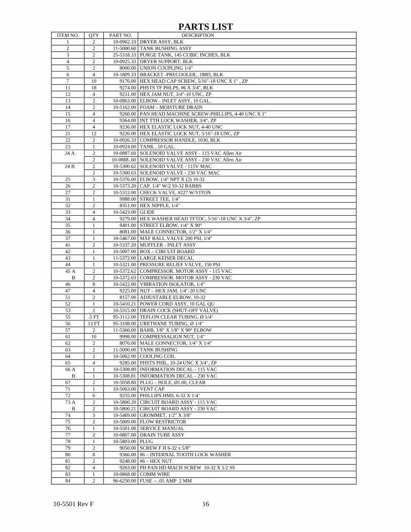
PARTS LISTITEM NO. QTY PART NO. DESCRIPTION
1 2 10-0902.33 DRYER ASSY, BLK2 2 11-5000.60 TANK BUSHING ASSY3 2 25-5318.33 PURGE TANK, 145 CUBIC INCHES, BLK4 2 10-0925.33 DRYER SUPPORT, BLK5 2 8000.00 UNION COUPLING 1/4"6 4 10-1809.33 BRACKET -PRECOOLER, .188D, BLK7 10 9176.00 HEX HEAD CAP SCREW, 5/16"-18 UNC X 1" , ZP
11 18 9274.00 PHSTS TF PHLPS, #6 X 3/4", BLK12 4 9231.00 HEX JAM NUT, 3/4"-10 UNC, ZP13 2 10-0863.00 ELBOW - INLET ASSY, 10 GAL.14 2 10-5162.00 FOAM – MOISTURE DRAIN15 4 9260.00 PAN HEAD MACHINE SCREW-PHILLIPS, 4-40 UNC X 1"16 4 9364.00 INT TTH LOCK WASHER, 3/4", ZP17 4 9236.00 HEX ELASTIC LOCK NUT, 4-40 UNC21 12 9226.00 HEX ELASTIC LOCK NUT, 5/16"-18 UNC, ZP22 2 10-0926.33 COMPRESSOR HANDLE, 1030, BLK23 1 10-0924.00 TANK , 10 GAL.
2 10-0887.60 SOLENOID VALVE ASSY - 115 VAC Allen Air 24 A2 10-0888..60 SOLENOID VALVE ASSY - 230 VAC Allen Air2 10-5300.62 SOLENOID VALVE - 115V MAC 24 B2 10-5300.63 SOLENOID VALVE - 230 VAC MAC
25 3 10-5376.00 ELBOW, 1/4" NPT X (2) 10-3226 2 10-5373.20 CAP, 1/4" W/2 10-32 BARBS27 2 10-5312.00 CHECK VALVE, #227 W/VITON31 1 9988.00 STREET TEE, 1/4"32 2 8351.00 HEX NIPPLE, 1/4"33 4 10-5423.00 GLIDE34 4 9279.00 HEX WASHER HEAD TFTDC, 5/16"-18 UNC X 3/4", ZP35 1 8401.00 STREET ELBOW, 1/4" X 90°36 1 8081.00 MALE CONNECTOR, 1/2" X 1/4"37 1 10-5467.00 MXF BALL VALVE 200 PSI, 1/4"41 2 10-5337.20 MUFFLER - INLET ASSY42 1 10-5007.00 BOX – CIRCUIT BOARD43 1 11-5372.00 LARGE KEISER DECAL44 1 10-5321.00 PRESSURE RELIEF VALVE, 150 PSI
45 A 2 10-5372.62 COMPRESSOR. MOTOR ASSY - 115 VAC B 2 10-5372.63 COMPRESSOR. MOTOR ASSY - 230 VAC
46 8 10-5422.00 VIBRATION ISOLATOR, 1/4"47 4 9225.00 NUT – HEX JAM, 1/4"-20 UNC51 2 8157.00 ADJUSTABLE ELBOW, 10-3252 1 10-5410.21 POWER CORD ASSY, 10 GAL QU53 2 10-5315.00 DRAIN COCK (SHUT-OFF VALVE)55 .5 FT 95-3112.00 TEFLON CLEAR TUBING, Ø 1/4"56 13 FT 95-3108.00 URETHANE TUBING, Ø 1/4"57 2 11-5366.00 BARB, 1/8" X 1/8" X 90° ELBOW61 10 9998.00 COMPRESSALIGN NUT, 1/4"62 2 8076.00 MALE CONNECTOR, 1/4" X 1/4"63 2 11-5000.00 TANK BUSHING64 2 10-5062.00 COOLING COIL65 4 9285.00 PHSTS PHIL, 10-24 UNC X 3/4", ZP
66 A 1 10-5308.80 INFORMATION DECAL - 115 VAC B 1 10-5308.81 INFORMATION DECAL - 230 VAC
67 2 10-5058.80 PLUG – HOLE, Ø1.00, CLEAR71 1 10-5063.00 VENT CAP72 6 9255.00 PHILLIPS HMS, 6-32 X 1/4"
73 A 2 10-5800.20 CIRCUIT BOARD ASSY - 115 VAC B 2 10-5800.21 CIRCUIT BOARD ASSY - 230 VAC
74 3 10-5469.00 GROMMET, 1/2" X 3/8"75 2 10-5009.00 FLOW RESTRICTOR76 1 10-5501.00 SERVICE MANUAL77 2 10-0807.00 DRAIN TUBE ASSY78 1 10-5803.00 PLUG79 2 9050.00 SCREW F H 6-32 x 5/8”80 8 9366.00 #6 – INTERNAL TOOTH LOCK WASHER81 2 9248.00 #6 – HEX NUT82 4 9263.00 PH PAN HD MACH SCREW 10-32 X 1/2 SS83 1 10-0868.00 COMM WIRE84 2 96-6250.00 FUSE -- .05 AMP 2 MM

10-5501 Rev F 17
KEISER SERVICE DEPARTMENT
1-(800)-888-7009
Keiser Corporation Telephone: (559) 256-8000
FAX: (559) 256-8100 Internet: www.keiser.com