compressor piping
TRANSCRIPT

8/7/2019 compressor piping
http://slidepdf.com/reader/full/compressor-piping 1/12
OEM BulletinCarrier
Corporation
CarlyleCompressorSa les

8/7/2019 compressor piping
http://slidepdf.com/reader/full/compressor-piping 2/12
INTRODUCTION
Refrigerant leaks have always been a major concern in any air conditioning or refrigerationsystem,Costs associated with refrigerant replacement and the reliability of the unit have given system designersand manufacturers the incentive to keep these refrigerant losses to a minimum. Recently though, theeffect of refrigerant discharges on the environment have created an additional concern.
Ozone depletion has become a major topic of interest in the nation and the world. The Environ-
mental Protection Agency (EPA) believes fully halogenated chlorofluorocarbons (CFC's) are one ofthe causes of ozone depletion. Unfortunately the most common refrigerants used today in refrigerationapplications (R-12, R-502) are all CFC's. The proposed EPA regulations on CFC's are expected toaffect both price and availability of these refrigerants and will result in a greater emphasis on avoiding
the accidental discharge of fully halogenated CFC's.
Carlyle has written the following bulletin to assist equipment manufacturers in the design of refrig-eration and air conditioning systems to avoid refrigerant line vibration problems. Vibration problems
can often result in broken refrigerant lines. This bulletin addresses design and retrofit considerationsfor refrigerant piping problems.
REFRIGERANT LINE VIBRATION
THEORY
Causes of vibration in discharge lines can be primarily separated into the following categories:1. Structural Resonances
2. Forced Vibration3. Acoustical Resonances
Of the above causes of vibration, structural resonances are the most common cause followed byforced vibration and acoustical resonances. Vibration can also be caused by multiple combinationsof the above. The following will discuss each type of vibration in the order listed.
STRUCTURAL RESONANCES
Structural resonances occur when the natural frequency of the discharge piping matches the frequencyof the discharge gas pulsations (exciting frequency). When the exciting frequency matches the frequency
of the piping, the vibration of the piping becomes greatly amplified. Imagine a tuning fork, it has aspecific frequency that it resonates at, and that is where the most vibration occurs. Thinking of apiping system as a very large tuning fork, it would have to be designed so that it did not have a
structural resonance at or near the exciting frequency of the gas pulsations. The resonant frequencyis a function of the stiffness and mass of the line. A discharge line should be designed as stiff and lightas possible to reduce the chance of vibration problems. However, in systems where start and stop kicksor other system motion occurs, flexibility must bedesigned into the piping system to absorb the motion.A stiff and light discharge line will have a higher frequency at which it resonates than one that is lessstiff and! or has more mass.' Troublesome discharge gas pulsations occur at relatively low frequencies,therefore systems with higher natural frequencies will have less chance of being affected by structuralresonances. Structural resonances are very difficult to predict. Extensively testing a piping design in a
laboratory environment, is the best method for avoiding structural resonances. When a design isfound to be free of structural resonances, the exact design should be used consistently in the future. Anychanges to a structural resonance free design, such as moving a fitting, would require retestingthe design. ' .
FORCED VIBRATION
Forced vibration isthe vibration caused by movement of the compressor (compressor driven vibration)
and! or discharge gas pulsations (pulsation driven vibration) emitting from the compressor. Theterm forced vibration excludes vibration due to any piping system resonances.
Compressor driven vibration is not a typical problem when the compressor is solid mounted, butwhen the compressor is spring mounted the chances of vibration problems are greater. Spring or rubbermounting kits are typically used in environments where vibration transmitted from the compressor tothe floor may cause excessive noise or damage to a,sensitive area. When spring or rubber mounting kitsare used, the piping system (which is where most vibration problems occur) must be designed toabsorb start and stop kicks, and handle the additional motion of the compressor during operation.This is usually accomplished by using flexible piping (vibration absorbers) and spring piping hangers.

8/7/2019 compressor piping
http://slidepdf.com/reader/full/compressor-piping 3/12
Although these items may reduce the transmission of movement of the compressor to the system,they may greatly enhance the effects of piping system vibration. The chances of pulsation drivenvibration and structural resonances increase with the introduction of springs into the system. Spring orrubber mounting of compressors issometimes necessary depending on environment andj or rack or unitdesign. Spring mounting generally makes piping geometry more complex and increases the possibilityof vibration problems. As a general rule, if there is no reason for spring mounting compressors orracks, don't.
On solid mount applications utilizing flexible piping (vibration absorbers), clamp the inlet andoutlet of the vibration absorber. Allowing one or both ends of the vibration absorber to flex canincrease the chance andj or magnitude of vibration problems. Carlyle doesn't recommend theuse of vibration absorbers in solid mounted compressor systems, unless they are securely clampedat both ends.
On spring mounted applications, vibration absorbers should be used only in accordance withmanufacturers requirements and recommendations. Typically vibration absorbers should be parallelto the crankshaft with the inlet clamped to the compressor or spring mounted base and the outletclamped to the solid mounted frame. When piping spring mounted compressors, try toarrange the compressor and piping to the straightest possible piping geometry. using as few bends aspossible. The previous statement holds true on solid mount systems as well, but spring mountedsystems usually become more of a problem because the discharge line has to be parallel to the crank-shaft. Careful planning can eliminate excessive piping and bends.
PREFERRED CLAMPING METHODSFOR SYSTEMS WITH FLEX PIPE
I ICOMPRESSOR
{.....
" .~. . . ", - ...
I ~
COMPRESSOR
~.... I
S PR IN G M OU NT S OL ID M OU NT
NO TE: O NLY DETAILS W HERE C LAM PS S HOU LD BE P LACED IN R ELATIO N TO FLEX P IP E, NO T A LL PIPIN G.
Gas pulsation driven vibration is the most common cause of forced vibration. Pulsation drivenvibration does NOT mean that the compressor is emitting such high pulsations that it forces the lineto vibrate regardless of the piping geometry. All reciprocating compressors emit discharge gaspulsa-tions (a reciprocating compressor generates a constant stream of pulsating flow). When discharge gaspulsations react with the piping system geometry in such a way as to set up an oscillating force, dischargepipe vibration may occur. An example .of this is when the discharge line comes off the compressorservice valve and enters I. 2. 3 or more elbows. Picture the pulsating discharge gas flowing from thecompressor through the first straight section of discharge pipe. The discharge gas then hits the first el-bow and bounces into the next section of straight pipe. An oscillation in the gas has already started andeach elbow may increase the oscillation creating a significant amount .of line vibration, Designing.thedischarge piping as straight as possible will reduce the chances of pulsation, driven vibration occurring.Another cause of forced vibration is the "Bourdon Tube Effect". When discharge piping forms a U
shape. the high pressure discharge gas tries to straighten the piping. resulting in vibration. Gas pulsa-tions have little if any affect on discharge lines composed of a single straight pipe.
ACOUSTICAL RESONANCES
Acoustic resonances result from the specific discharge gas properties and the piping system geometry(not the structural dynamics). The effect of acoustical resonances is to amplify the gas pulsations atspecific location in such a magnitude as to cause significant vibration. There are many types of acousticresonances and most are very difficultto predict. The most common type results from longitudinalstanding wave patterns. .
2
8/7/2019 compressor piping
http://slidepdf.com/reader/full/compressor-piping 4/12
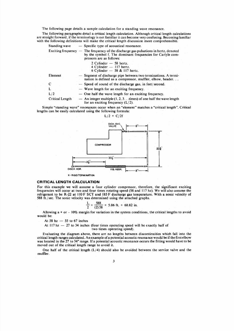
The following page details a sample calculation for a standing wave resonance.
The. following paragraphs detail a critical length calculation. Although critical length calculationsare straight forward, if the terminology is not familiar itcan become very confusing. Becoming familiarwith the following definitions will make the critical length discussion more comprehensible.
Standing wave Specific type of acoustical resonance.
Exciting frequency - The frequency of the discharge gas pulsations in hertz, denoted
by the symbol f. The dominant frequencies for Carlyle com-pressors are as follows:
2 Cylinder - 58 hertz.4 Cylinder - 117 hertz.6 Cylinder - 58 & 117 hertz.
Segment of discharge pipe between two terminations. A termi-nation is defined as a compressor, muffler, elbow, header ...
~ Speed of sound of the discharge gas, in feetj second.
Element
C
- Wave length for an exciting frequency.
- One half the wave length for an exciting frequency.
- An integer multiple (1,2,3 ... times) of one half the wave lengthfor an exciting frequency (Lj2).
Simple "standing wave" resonances occur when an "element" matches a "critical length". Critical
lengths can be easily calculated using the following formula:Lj2 = Cj2f
L
Lj2
Critical Length
DICH.SVC. I---'~VALVE ~ I 8 .. I, ~L
20 t
1 : = : = -13r= -~ -·! 33f' Jox vmmmmw xJDISCH. HOR. VIS. A8SR. I---8"---1
COMPRESSOR
X-RIGID TERMINATION
CRITICAL LENGTH CALCULATION
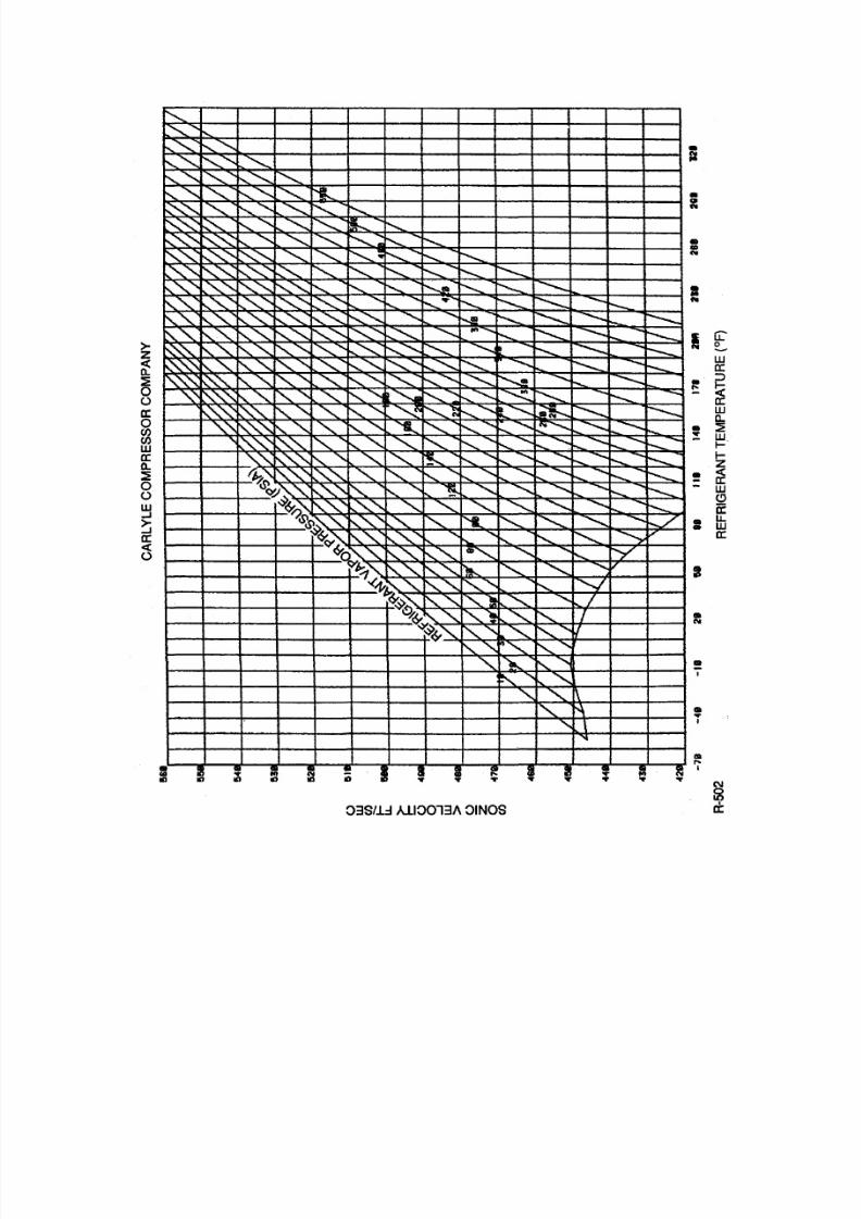
For this example we will assume a four cylinder compressor, therefore, the significant excitingfrequencies will occur at two and four times rotating speed (58 and 117 hz). We will also assume therefrigerant to be R-22 at 110F SCT and 185F discharge gas temperature. With a sonic velocity of588 ft.j sec. The sonic velocity was determined using the attached graphs.
L 588 .2= (2) 58 = 5.06 ft. = 60.82 m.
Allowing a + or -10% margin for variation in the system conditions, the critical lengths to avoidwould be:
At 58 hz - 55 to 67 inches
At 117hz - 27 to 34 inches (four times operating speed will be exactly half oftwo times operating speed).
Evaluating the diagram above, there are no lengths between discontinuities which fall into thecritical length ranges calculated. An example ofa potential acoustic resonance would be if the first elbowwas located in the 27 to 34" range. If a potential acoustic resonance occurs the fitting would have to bemoved out of the critical length range to avoid it.
One half of the critical length (L/4) should also be avoided between the service valve and themuffler;
3

8/7/2019 compressor piping
http://slidepdf.com/reader/full/compressor-piping 5/12
DESIGN RECOMMENDATIONS
Through the utilization of good design practices forced vibration, and acoustical and structuralresonance problems can be kept at a minimum. There is no design method that will eliminate allpossible vibration problems 100% of the time except through experimental testing of each system.From the previous material, it is shown that predicting vibration problems can be very difficult andcomplex. Itshould be noted that when a system is designed and found to be free of vibration problems,that particular design should bereused in its entirety. NOTE: Vibration problems may be created by any
changes to the design - i.e., different dimensions, additional fittings, different mufflers ... In conclusionif you find a design that works, keep it.
The following is a list of good design practices:
I'. Keep line as stiff and light as possible. Keep inmind that the line may require inherent flexibilityto handle any system motion (start and stop kicks . .. ).
2. Keep lines as straight as possible. Use formed discharge lines in place of elbows whereverpossible. Ifelbows must be used, use long radius in place of short radius. Use 45 degree elbowsor bends in place of 90's wherever possible. Use Y's or a45 degree bend in plaeeofT's whereverpossible. Use fittings of the proper size, don't reduce line size for fittings. Don't use fittings thathave large pressure drops, such as sharp 90 degree elbows.
PIPING PRACTICES
NO TYPICAL PREFERRED
TYPICALHIGH ap FITTING
TYPICALSHORT RADIUS
BETTERLONGRADIUS PREFERRED
FORMED BEND*
*A FORMEDRADIUSOF10PIPE DIAMETERS ACTS ACCOUSTICALLY AS A STRAIGHT LINE.
3. Use largest practical discharge line diameters possible. Practically speaking, if a line is sizedfor a given load and proper oil entrainment, there is usually no significant increase in line sizepossible.
4. When using solid mount compressors with vibration isolators, clamp the isolator at both ends.
5. Detemine whether spring or solid mounting is appropriate.
6. If natural frequencies have been occurring in existing designs, redesign piping system.
7. System geometry should be checked by calculating standing wave resonance.
8. Carlyle compressors are supplied without valves to allow flexibility in sizing refrigerantlines. Always calculate both suction and discharge line sizes and use the appropriate servicevalves. Although we recommend using the most generous discharge line diameters practical,please note that oversizing lines can result in oil return problems. Refrigerant lines shouldalways be sized to handle the design, maximum and minimum load conditions.
9. When using mufflers, place them as close to the service valve as possible and/ or before the firstfitting. Ideal placement of the muffler isnot always possible, but note that a muffler is ineffectiveupstream of itself.
4

8/7/2019 compressor piping
http://slidepdf.com/reader/full/compressor-piping 6/12
EXISTING SYSTEMS
To eliminate vibration problems in existing system. the cause of the vibration should first be deter-mined. Structural resonances are the most common problem. they can usually be detected andcorrected by the addition of mass to the line. This may sound contradictory to the statement thatlines should be designed as light as possible. When a system has a structural resonance it is becausethe piping has a natural frequency at the same range as the discharge gas pulsations. The easiest way toeliminate this problem is to add mass to the discharge line which can effectively lower the natural
frequency of the piping. This is a very effective method of tuning the system out of the range of the gaspulsations frequency. The addition of mass can be in the form of a muffler and in some cases anexisting muffler can be the culprit in the system. For example. if your system is designed so that thenatural frequency of the line is greater than that of the gas pulsations. the addition of a muffler may addsufficient mass to drop the natural frequency of the discharge line to the range of the gas pulsations. Theaddition of mass could also be in the form of a plastic molded weight that could be slid up and downthe discharge line. Moving the mass around the piping to find its most effective position. can be a veryeffective means of tuning a system. If a weight is used in a system, make sure it is rigidly attached to therefrigerant line. If a weight isallowed to move independent of the line it may cause wear and potentiallya leak. Clamps may also be added to increase the stiffness of the line. and are very effective. The use ofclamps is discussed later in this section.
NOTE: In the event of trying to tune a system. using aplastic or lead molded weight. use caution.Make sure the high temperature of the discharge line doesn't melt the material or cause it to give offtoxic gas.
Forced vibration is the next most common cause and can be corrected by using mufflers. baffleplates. larger discharge lines, reduction of bends, long radius elbows, formed discharge lines. andclamps. To determine ifa muffler will beeffective. throttle the discharge valve for approximately 20 PSIincrease in discharge pressure. The pressure increase does not occur until the valve isalmost completelyfront seated (WARNING: Do not completely front seat valve. This will cause extreme internalcompressor pressure which may cause compressor damage and potentially rupture thecompressor). If the piping vibration subsides with the throttling of the discharge valve, a muffler willusually be an effective application.
Forced vibration is generally due to gas pulsations, but in rare instances may be due to compressorimbalance. Motor or coupling problems can also be the cause of forced vibration in open drivecompressors. To determine whether the vibration is due to compressor imbalance or gas pulsations thefollowing method can be used.
I. Tum compressor off.
2. 'Shut the suction and discharge service valves.
3. Bleed all pressure from compressor.4. Remove both service valves.
S. Secure a rag over the discharge port to separate oil mist.
6. Run the compressor for a short period of time (10 to 15 seconds) on air.
7. During run time examine compressor for imbalance.
WARNING: Oil mist is extremely flammable. be sure to use the oil separation method instep #5. Make sure both service valves are removed from compressor.
This method quickly determines imbalance problems on 06DjE compressors, but on S F / H
compressors it has only narrowed it down. On SF I H compressors. if imbalance occurs after runningthe compressor on air, check the coupling alignment and then run the motor by itself. When usingthe above methods. take into account any start and stop kicks due to the mounting method of aweak base.
Muffler and baffle plate pros and cons will be discussed later in this bulletin. Please note that when
using clamps they will be most effective ifplaced in the direction ofmaximum motion. Ifa line ismovinghorizontally and you clamp it vertically, the clamp is less effective. Clamping lines can be very effectiveand is usually the easiest method to correct vibration problems, but unless the lines are clampedproperly. the problem may become even worse. When clamping lines, they must be clamped to some-thing that is more stiff than the discharge line to be effective. Clamping a discharge line to a light pieceof channel may cause the channel to resonate. If the channel begins to resonate it may cause noise.andj or transmit vibration. The clamp itself should be made of a rigid material that is more stiff thanthe discharge line.
5
8/7/2019 compressor piping
http://slidepdf.com/reader/full/compressor-piping 7/12
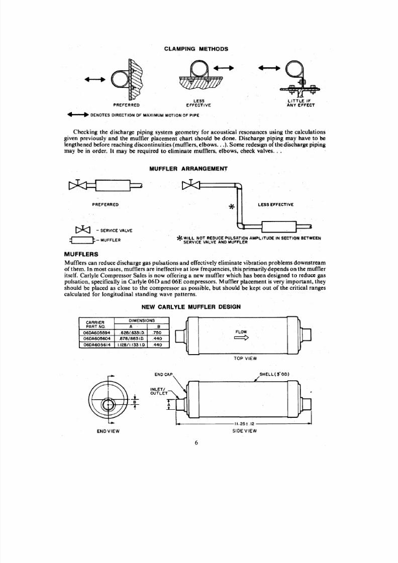
CLAMPING METHODS
PREFERRED
.. • DENOTES DIRECTION OF MAXIMUM MOTION OF PIPE
LESSEFFECTIVE
LITTLE IFANY EFFECT
Checking the discharge piping system geometry for acoustical resonances using the calculationsgiven previously and the muffler placement chart should be done. Oischargepiping may have to belengthened before reaching discontinuities (mufflers, elbows ... ). Some redesign of the discharge pipingmay be in order. It may be required to eliminate mufflers. elbows. check valves ...
MUFFLER ARRANGEMENT
PREFERRED
[ ) t : : : J - SERVICE VALVE
' *LESS EFFECTIVE
* WILL NOT REDUCE PULSATION AMPL.ITUDE IN SECTlQN BETWEENSERVICE VALVE AND MUFFLER~...__ ~~_ MUFFLER
MUFFLERS
Mufflers can reduce discharge gas pulsations and effectively eliminate vibration problems downstreamof them. In most cases. mufflers are ineffective at low frequencies, this primarily depends on the muffleritself. Carlyle Compressor Sales is now offering a new muffler which has been designed to reduce gas
pulsation. specifically in Carlyle 060 and 06E compressors. Muffler placement is very important. theyshould be placed as close to the compressor as possible. but should be kept out of the critical rangescalculated for longitudinal standing wave patterns.
NEW CARLYLE MUFFLER DESIGN
1 4 - -' : _ -= - - = - ~ - = - - = - - = - - = - - = - - = - - = - - = - - = - - 1 - 1 .- 2 5 -. - _ . ~ 1 2 -- - - - - - - - - - - - - - - - - - -. . - - - ~ Y - - . - . I . ISIDE VIEW
CARRIERDIMENSIONS
PART NO. A B
06DA605594 .628/.6331.0. .150
06DA605604 .818/8831.0. .440
060A605614 1.12811.133 1.0. .440
END CAP
INLETIOUTLET
EN D VIEW
FLOW
~
TOP VIEW
SHELL (3"00)
6

8/7/2019 compressor piping
http://slidepdf.com/reader/full/compressor-piping 8/12
c,
Mufflers are typically not needed in system designs. Reciprocating compressors emit gas pulsa-tions and these pulsations sometimes react with specific system designs and cause vibration. In thesesystems where pulsation driven vibration has proven to be a problem, a properly sized muffler shouldbe used.
Mufflers can be used to effectively reduce piping system noise. Lengthy piping runs often developan audible pulsating noise. The use of mufflers in systems with remote condensers has proven veryeffective at reducing piping noise levels. The new muffler offered by Carlyle is recommended for 06Dcompressors in systems with piping noise problems.
As discussed previously the addition of a muffler can add sufficient mass to a discharge lineto causethe natural frequency of the line to fall into the range of the gas pulsations. Mufflers can cure problemsif used properly and can also create them. The question of whether a muffler isneeded should be thoughtout in the design process.
CARLYLE RECOMMENDATIONS
I. Mufflers should be used on all 06ER 166(now becoming obsolete) and 06ER099 compressors.
2. Mufflers should be used on all 06EM266 (now obsolete) and 06EMI99 compressors.
3. Mufflers should be used on all 06E compressors with capacity control.
4. Mufflers should be considered on all 5F I H standard stroke compressors and are requiredon all 5F I H long stroke compressors.
BAFFLE PLATES
Baffle plates are basically an orifice used to create a pressure drop and reduce discharge gas pulsationamplitude. Baffle plates can be very effective at low frequencies, where mufflers offer limited atten-uation. The use of baffle plates will increase the discharge temperature, but for most applications theamount is insignificant. Baffle plates are also very easily installed in a system. The orifice on a baffleplate is designed to reduce discharge gas pulsation amplitude at full load, but when unloaders are usedthe baffle plates effectiveness becomes very limited. In effect a baffle plate can eliminate vibrationproblems at fuJIload, but at part load vibration problems may appear because of the lower mass flows.
NOTE: Baffle plates are designed to create a 6 - 10 psi pressure drop.
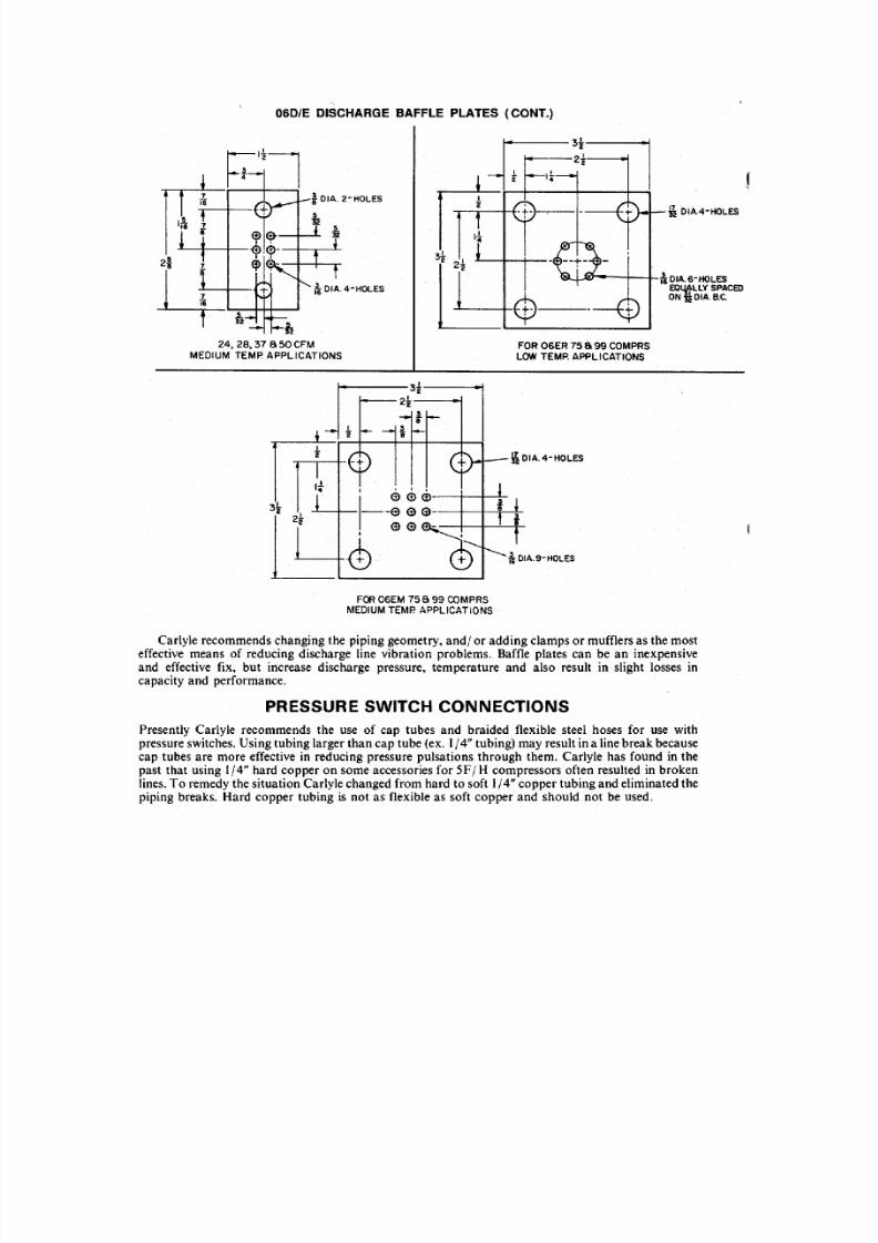
06D/E DISCHARGE BAFFLE PLATES
;\ O IA" 3- H OLE SON t OIA. B.C.
-M ! O IA . 2 - H OLE S
.13,16,18 S 20CFM 24, 28,37 S50 CFM
LOWTEMP. APPLICATIONS
7
8/7/2019 compressor piping
http://slidepdf.com/reader/full/compressor-piping 9/12
06D/E DISCHARGE BAFFLE PLATES (CONT.)
24, 28,37 850 CFM
MEDIUM TEMP APPLICATIONS
~ DIA.4-HOLES
FOR 06ER 75 8 99 COMPRS
LOW TEMP. APPLICATIONS
FOR 06EM 75899 COMPRS
MEDIUM TEMP. APPLICATIONS
Carlyle recommends changing the piping geometry, and/ or adding clamps or mufflers as the mosteffective means of reducing discharge line vibration problems. Baffle plates can be an inexpensiveand effective fix, but increase discharge pressure, temperature and also result in slight losses incapacity and performance.
PRESSURE SWITCH CONNECTIONS
Presently Carlyle recommends the use of cap tubes and braided flexible steel hoses for use withpressure switches. Using tubing larger than cap tube (ex. 1/4" tubing) may result in a linebreak becausecap tubes are more effective in reducing pressure pulsations through them. Carlyle has found in thepast that using 1/4" hard copper on some accessories for SF/ H compressors often resulted in brokenlines.To remedy the situation Carlyle changed from hard to soft 1/4" copper tubing and eliminated thepiping breaks. Hard copper tubing is not as flexible as soft copper and should not be used.
8/7/2019 compressor piping
http://slidepdf.com/reader/full/compressor-piping 10/12
> -z~~oC , . )
II:
o(/)
(/)
WII:0 . . .
~oC , . )
W...J
~II:
( 3
~~",,,",,. . . . . . . . . . . .
r-;............. . . . . . . . . _ _ " ' <,~ - . . . . . . . ,<:. . . . . . . . - - . . . . . . . . . . . . .
<,i ' . . _ , <,,. . . . . . . . . . . . <,~
~ - . . . . . . . , <, ~"' <,,r-,
l ' - - . .'"0.. r - - . . _ - . . . . . . . . . <,- - . . . . . . . . . . . . . I ! . . . . . <,
i ' . . . ' " ~ " " ", - - . . . . . . . . . <,<,1 ' - - . . . .<, <,
~"" ":-.........c-, <,<, r - - - . .. .. ; . . . . . . . . . . . . . . . . . r - . . . . . ~
~ . . . . . . . . .
" ' " , " " " ~ <, r-, <, r - . . . . . r-, '-: - - . ,': - - . . . . " <,<,~'-..: " - . . . . . r-, . . . . . . . . ...........l1li i'-.... . . . . . _ : : - - - -
," : - - . . . . ' : - - . . . .,'2 ' . . . . . - " " " ' " 0-...'<, . . . . . - . . . . . . . . . . . . . ~. . . . . . r - . . . . . "-. . . . . . . . . . . . . . . -._~"," , - - . . . . . . . . : ~ " " ' ", " ' " t " . . . . . - " " " " " _ <, . . . . . . .
~. . . . . _ - - . . . . - - . . . .
"-.-. - - -~",. . . . . . . . . . " r - - . . . . _ - . . . . . . . , . . . . . . . . . . . . - - . . . . . . . . . - : - . . . . . . .'. . . . . _ _. . . . . . . . . . . <, . . . . . . . . . . .!'-. i ' - . . . . . . . . . - - ~ .....r--.
~"-. ,". . . . . . . . - . . . . . . . . . . f ' . . . . - " " " " . . . . . . . . . . . . .',"-.., . . . . . . . . . .- - . . . . . . . . . . . : : - - . . . . . . . . - - . . . . . . . . . . . " r - - . . . . . . . - - . . . . . . . r-..~~ ," . . . . . . . . - . . . . . . . . . 1 ' . . . . - " " " " <,~ . . . . . . . . . . . . ' - . . . ._- . . . . . . . . . . . . .- . . . . . . . . . . . . . r-, - - . . . . . . . . . . . . . . . . . . - - ._
~""~". . . . . . . - . . . . . . . . . 1 - " " " " ' " <, r - - . . . . _ - - . . . . . . . . . <,. . . . . . . . . - . . . . . . . . . . - . . . . . . . . . . . . . ~ - . . . . . . . . . . . .
- - -' "~"""1'....' <, 1 ' . . . . " ' - 1 - . . . . . . . . . . . . . . . . . . . . . . . - . . . . . . . . . . . .. - - . . . . . .. . . . .
""r-; . . . . . . . .
: - . . . . . . .
-, " ' " 0 . . _ " 1 ' - . . . - " " " " <, r - . . . . . . - . . . . . ; <s,~. . . . . . . . - . . . . . . . . . t.............~ - . . . . . . . . . r:----~'\ ,,,-~~-"" <, r - - . . _ " , - . . . . . . <, . . . . . . . . . . . . . . . . ~ - - . . . . . . . . L~ : - . . . . . . . . - . . . . ~
"- 0.. .~ ~'"- . . . . . . . . . _ ' i ' . . . - " " " " "<,<, . . . . . . . . . . - - . . . . . . . . . . . . . . . . . . . . . . 1 - - " . . .. . .. . .. . .t.....-""'_ r--...- . . . . _ -
" ' " r ' - . " " ", - . . . . . . <,<, s, , - . . . . . . . . . . . . . - - . . . . . . . . . . . . . . . . . . . . . r-..._- 1 "- .... .... . . . . . . . . . . .
I '~~~"x-c-, <r-, ," , - . . . . . . . . . - . . . . . . . - - - . . . . . . ~ - . . . . . . i'-. . . . . . . . . . . .~ ~ " ' i 'o . . , , " , - . . . . . . .~ <, <, . . . . . . . . . . . . - - . . . . . .t - . . . . . . . . . . . . . . . .~~~..........' <». <, <,<, - - . . . . . . . . . . . . . <, - - - . . . . . . . . - . . . . . .
~
\ S'I&~" ": --." ':--" " r-, C " a . r-, - . . . . . . . . . . . . . . <, - . . . . . . . r--.../~<$-0r- ,<, i ' . . . " . . . . . . . . .' " "r-, r-, <, ~
v
~~,," <,-.........,'4 » - . . . . . . . . . . . . . . . . . . . . . . .
,. . . . . . rY"
7 > : . , " - . "<,-,<,~ r-, <, - - - . . . . . . V '
- < : 1 ' ~ _ , , : - - . . . . . .<,. . . . . . . . . . . - . . . . . . . . r . . . . . . . <r
~~~ r-,<, """!l <, <, /
~ \ . . - . . . . . . . . . ,,~<,r-, I~ ~ c $ - "- . . . . . . . . . ' <,1'..... ' {
'"<, 1 ' . . . . '
<, ~ , ,~~ - . . . . . . . <,
" " "<, 1 \<, ~
<, \- . .
• ! : ;: i ~ I ! , l!! !, ~ ;: 5. . .
III II) o n 10 . . . . . . . . .
03S/.1.::1A.lI0013A OINOS
•~
•~
••N
•tottil
Iu : : -e,WII:
~: : : : l
~II:
W0 . . .
• ~:!
~-
I-Z
!! [ 2- woa :
• u,
• WII:
It
•N
•I
•. . .I
lSIr-I
C\I
f 5d:

8/7/2019 compressor piping
http://slidepdf.com/reader/full/compressor-piping 11/12
> -zc(a,
~
ooa:oC/)
C/)
wa:a ..~ooW...J
~a:
C 3
~ "- " 'K~ 1" - - . . , " " ' - . <,t " - . ' - - . . I'..,<, <,r-,
" " " "<, , , " " <, s,
" , " " " <, r - . . . ~ <, 1 ' - - - - .. . . . . .. t - . . . . .
~""~ i'.,"" - . . . . . . . . " I'.... 1-....'
" " " " . . . . . . . e-, <,<,f " - . . . . . " l t -. .. .. . . .. .. .. ","-
~ " "t'0.."- <,<, r-, r - . . . ~ ~ " " " " f....-"';;""
i " . . . " " "<,r-,'"
! ' . . . . . . .~ I"" I'.... r - . . . " ' " t - "' . . . . . . . . . . . . .
. . . . . . . . . . . , . . . . . . . . . . . . . .
r-,"""-......~""-~ " ' " 1'-...' 1"-..'
<, ."". . . . . . . . . . . - . . . . . . . . . . <,I - . . . . .
. . . . . . r-..
" ' " " "i " . . . ' - . . . . " " " <:-.~<,
' " "<,<SI~ "" '"'
. . . . . . r-.. F . ; ; : : : : :
I,<,r - - . . . " ' " 1 ' - . . . . . . . . . . . . . . r-,<:r-;.-, <, "'. . . . . . . . . . . . . . <, '"'
. . . _ ~ r-... - -.""f"..." r - - . . . . . . . . . . . . . ."'. . . . . . . . . . . . r-,<,I " - . . . . . . r - - - . . . , . . . <, . . . . . . . . . . . . . . .
. . . . _ . . . . . .f - . . . . . - - . . . . . . . . . . .
" " " 1 ' - . . . . " . . . . . . . . . ."1'-.."" ['.....<, ~ . . . . . . . t - .. . _ '" r - - - . . . . r-; . . . . . . . . . _ - t - - . . . I'-- -10..." 1 ' - . . . . " 1"'-.." " " . . . . . . . . " " . . . . <,K'="
. . . . .'" I " " " - - - . . . ~ r-- --.:.
~""f'-."I, <, "",,' ~ ,,~ r-,........,h§s-, <,~ l'--. ", . _ - - . . . . . . .
'''''' t-..." 1 ' - . . . . " ' " " " " - ' "<, t........,"" <,~,. . . . . . . . . . . . . . . . . . . . . .
I - . . . . . - . . . . . . . . . : : : : : - -" " " r - . . . " " r - . . . . . " " - 1"-. ' "' <, t r - . . . . . . " " <, r - . . . . - - - - ; <,~ . . . . . . .r - . . . . . . ~
" ' " ~" ' "r - . . . " " - " " ' . . . . . . . . .<, "' . . . . . . . . .
<, t r - . . . . . . . . . , t - . . . . ' : : : - - . . . . . . . . . . . . . . . . . . r - . . . . . . . r - - . . . . . . .
, , " , " , '~",. . . . . . . . . . <, ",,,,, <, t r - . . . . . . . . . ' "<SI~ ~ . . . . . . . . . . . . . . . . . . . . . . _ r-._
' " ' ' ' , , " ' - '<, <, " , - . . . . . . . . . . , <; 1 " - . . . . . . ' ,N.............<, ~
. . . . . . . . _ . . . _ _'\
C ' -." ' "t ' r - . . . " " -
" . . . . . . . . <,<, t--....' "-: <,<;~
- -. . , _ . . ,
""2 ' - . . ' - ' <, <, I'-.. <, <, <, ~ . . . . . . . . . . . . . . - . . . . . -<,
r - . . . " ' - ", , , , , - <, <, <, <, ~ '<; ~
" ' " " " "tJ.,;,'-...........'" ~ "'" <, <, <,<, r-, r-; . . . . . . . . . _ - . . . . . . . . . . . . . . : . : :
~ O V " " " " " ' ' ' ,. . . . . . . . . . .' - . . . : . ' " <, r-; r-, K s, <;
"" " " "~~ ..............<,<,<, r - . . . . . . . . . . <, <, <, . . . . .t - . . . . ._ f'::: ~
'?IS'~<,<,<,:'....<, <, <, <, ~ . . .. . f . .. . ~
~ ~ ' ' ' ' ' ' ' ' ' ' ' ' ' ' t ' - . . . . <,r-, '<, . . . . . . . . : : . . : . '"V( ) I ~ ,<, I ' . . . . .<r-,<, <, <;
"- Ht. '7
O() l~K"" -<," <, <,
" " " ' " fY 7- - 1 - < ." " " " , . . . . . . . . . . . . . . . ~
1tb-~<,<,<,......<, "1
~~,<,<,......<,<, -: t
~~'"<, ~ " " " I
~~, <, <,
"II
<, ' "<,Ii!,. . . . . . . . . . <, l
<, <; r-Jr-, <, '\<, . . . . . . . .
~i~
I L ~ ! ~!! . ; l I
, . II lI', a . •N
o n o n . . . . . . . . . . . .
03S/.u Al.I00131\ OINOS
IIICD
'"
II'"
•a
I
III
~
•1ftN
c~
I wN a:
: : : : >
! ; {lSI a :!:; w
a,
~lSI
W
:!l-
I-Z
~~w- oa :u,
I wa:
IIIt I C >
r :
•I
III. .•
III
"I
C\ I.. -I
a:

8/7/2019 compressor piping
http://slidepdf.com/reader/full/compressor-piping 12/12
> -zc(
a ..:: E
ooII:
oCI)
CI)
WII:a ..:: EooW...J
~II:
( §
<,r-,r-,.-, f " . . . . . . . . . . . .t-.,['....'-.-;
" ' ". . . .
<,r - - . . . . ~ t ' . .. , . . . . .. . .t - . . . . : - " " "<, r - - . . . . " " ~ . . . . . . "' . . . . . . . . . . . <,
~ t " - . . . . ' -""-. r - - . . . . . . . . . . . . .. . <,s-:
~"t - - . . . . . . . . . . . . <," " ' . . . . . . r-..' 1 0 " " " - . . . . . . . . . . : . . :
~ " "~ <,r-, 1 ' - . . . . . . . . . . . ."-. . . . . . . . . . . .I e ' " " "
. . . . . . . . . . . . . .
~,0...,t " - . . . . " " - . <, 1 ' - . . . . . . . . . .. . . . . . . . . . . . . . . . . . e<; . . . . . . . . . . . . . . <;
,,"-..<,~"~<,I : ' . . . . . r - . . . . . . . . . . . .t--...' ""t: <, - . . . . . . . . . . . . : - . . . . . .1'-..'( ~ ""r-c-; I '-...~ t - -. , . .. .. .. ... . . . . . . . . . . . . . . . ~ <, ~ "" r0- t--.
l'...'-'~"" ' - , ~~ . . . . . . . . . ~<, <, <, ~ . . . . . . . . . . . . . . . . .I - - . . . <; ~ . . . . .
: : - - . . . . " [ ' . . _ " " - . . t " - . " ' - ' ""-..~ r - - . . . " " " t - - . . . " " " ' - . . . . . . . . . . . . . . . . <, <,. . . . . . . . . .
~ r - - . . . . . - - : . . . . . : . . . . .
~, ~,- " " . ' 1:'..." ['...,. . . . . . . . . . l'--.<,~ <, . . . . . . . . . . . . . .f . . . . . " r - - . . . . . ~
.....:;
~~ " " ' - ' ."-... . . . . . . . ~ . . . . . . . i ' . . " . . . . . ." - " ' " r - . . . . - - " " " " " : r-, <,- . . . . . . . . . . .. . . . . . ."-- ~ " " " ",,~~ " " ' - ,"", ,- ~ - . . . . . . . . . . :t'-..." C ' - - . . .. . . . . . . .. . . . . . . . . . . . . . . . . . . :<, ~ 'f.... ~ ~
"~~ ,,,-"'''-f"'..,.'-
: ' . . . . . _. . . . . . . . ."-~ . . . . . . . . . . . . . . . . . . . . . . , ....,.;:
I " " ""'-" i'.." 1"-<,
~ . . . . . .
"'''
. . . . . . . . . . . . . . . . . . . . . . . . . . . . . . . . . . . ~ r . . . . . . . . ~ f':::
' "~~
: - - . " ". . . . . . . .
<,t - . . . . , . . . . . . . . .. e-, ~ . . . . . . . . . . . . . . . . .~ . . . . . . . . . . . . . . : . . . . . . . . . . . . . . . . . . ."-
i'.."'0
~"1"-<, <,,
. . . . . . . . r--, s-, ~,~ ~ r-.-
"~~ ~,<, i'... ........~ <,. . . . . . . . . . . . . . . . t--.............. - . . . . . . . : : : . . . . . . . . . . . . . . . . . . . . . . . . . . .
f'.."" t " - . . " "<, i'... .........
"<,<, r - . . . . . . ' r - . . . . . " ' " f....~ f....""'"
n ,-,,,,,,,,,-,,~ ~ .... .. .. .<,"e.<, 1 ' . . . . . " " "'-..'"'-.."'" r-.""~& ~ "'" ~'" ~ <, <,<;<,
. . . . . . . . . . . . . . . . . ,. . . . . . r . . .. ._ . .. .. .r---_
< > v ~ ~ " r . . . . . " "l'-..."-.. r-, r-, : - - e . . . . . . . . . . . . . . . . . . . . . . . . . . . . . . . . , . . . . . . . . _ _
~oSI~~ ,~ ' " r . . . . . ~ . . . . . . .. . . . . . . . . . . . . . . . ~ . . . . . . . . . . . . . . . . . . . . . . . . . . . . . . . . . . . "'-..
~ ~ " '~ . . . . . . . . . . . : C ' . . . . . . . . . . . . . <, "'-t <, <, " " " r - . . . . .7
( ) ' Q -a "" , - " ~ " , , "<,<,<,<;7
( ) ' I > ; , " i'..<,r-," i'...i r-, r-; <,- < _ 1 - b - J r - . , , . ' <,<,
<,""
,. . . . . . .........1
~~.....<,........<,""",,-<, · r
19/~:".....
"~~ r":: 'I
~~<$ - ,,,- ~~ <,! ' - . . I<,~"<,N
i'..."" ~ N<;<,i'...\
~ I'-.. '\ .. . . . . . . ~
~ 1 \I'l
" "lIi
" • II III • - I I I - . -III II II:I(II
. .ca
. . .III
. . .III
onca
03S/1.:I A.lI0013A OINOS
•ro o. .
•g :
!
:I. . . .
!LL~w
• II:
~ : : : >
~II:W
til a ..:! :: E
w~~
!! z- ~
w~
C D II:III U.
WII:
:8
•ro o
til
I
C D. . .I
~I
C\JC\JI
II: