compressor wabco
TRANSCRIPT
7/27/2019 Compressor Wabco
http://slidepdf.com/reader/full/compressor-wabco 1/6
TP-02122Revised 02-07
Installation Guide
TP-021216579/22882 Revised 02-07Printed in the USA Copyright ArvinMeritor, Inc., 2007 Page
Cylinder HeadReplacement Kit
Part Number 911 906 800 2(Replaces Part Number 911 153 931 2)
WARNING
To prevent serious eye injury, always wear safeeye protection when you perform vehiclemaintenance or service.
Remove all pressure from the air system beforeyou disconnect any component. Pressurized aircan cause serious personal injury.
Park the vehicle on a level surface. Block thewheels to prevent the vehicle from moving.Support the vehicle with safety stands. Do notwork under a vehicle supported only by jacks.Jacks can slip and fall over. Serious personalinjury and damage to components can result.
For technical assistance, please contact theArvinMeritor Customer Service Center at
800-535-5560. For your reference Meritor WABCOservice and maintenance publications are availableon our web site:
www.meritorwabco.com
The instructions given in this bulletin are general.Depending on the type of vehicle involved,additional steps may be required. For example,there may be a power steering pump installed atthe back of the compressor and most installationswill have a governor mounted to the side of thecompressor. Refer to the vehicle manufacturer’smanual for information about removing andreplacing these components.
NOTE: Air and water fittings are not included inthis replacement kit. If it is necessary to replaceany of these fittings when installing the newcylinder head, use steel replacement fittings only.
Cylinder Head Replacement
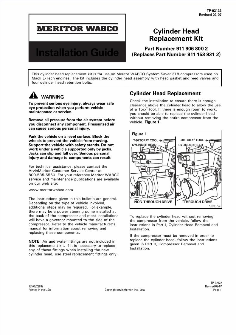
Check the installation to ensure there is enoughclearance above the cylinder head to allow the useof a Torx® tool. If there is enough room to work,you should be able to replace the cylinder head
without removing the entire compressor from thevehicle. Figure 1.
To replace the cylinder head without removingthe compressor from the vehicle, follow theinstructions in Part I, Cylinder Head Removal andInstallation.
If the compressor must be removed in order toreplace the cylinder head, follow the instructionsgiven in Part II, Compressor Removal andInstallation.
This cylinder head replacement kit is for use on Meritor WABCO System Saver 318 compressors used onMack E-Tech engines. The kit includes the cylinder head assembly with head gasket and reed valves andfour cylinder head retention bolts.
Figure 1
NON-THROUGH DRIVE THROUGH DRIVE
T-30 TORX® TOOL T-30 TORX® TOOL
CYLINDER HEAD CYLINDER HEAD
1003372c

7/27/2019 Compressor Wabco
http://slidepdf.com/reader/full/compressor-wabco 2/6
TP-02122Revised 02-07 16579/22882Page 2 Copyright ArvinMeritor, Inc., 2007 Printed in the USA
I. Cylinder Head Removal and Installation
A. Removal
1. Set the spring (parking) brakes and block thewheels of the vehicle.
2. Drain the air pressure from the system.
3. Drain the engine coolant system and thecylinder head of the compressor.
4. Use a cleaning solvent to remove road dirt andgrease from the exterior of the compressor.
5. Remove the air and water lines leading to thecylinder head.
6. Remove the four hex head bolts that attach thecylinder head to the crankcase. Remove thecylinder head and cylinder head gasket.
Figure 2.
7. Use a cleaning solvent to clean the top of thecrankcase.
NOTE: The piston bore must be kept free ofdebris. To avoid getting debris in the piston bore,cover the top of the crankcase with a clean cloth.
B. Installation
NOTE: A T-30 Torx® tool is required for thisprocedure.
Before you begin, remove any protective coveringfrom the top of the crankcase and inspect thepiston bore to ensure it is free of debris.
Cylinder head valve components MUST be alignedin the proper position in order for the compressorto function.
1. Align the hole in the cylinder head gasket withthe unloader passage on the top of thecrankcase. Figure 3.
2. Install the sliding leaf. The two holes in thesliding leaf must be installed over the two pinson the base of the cylinder head. Figure 4.
When removing the cylinder head from thecrankcase, do not damage the crankcasesince it will not be replaced.
Figure 2
Figure 3
Figure 4
Remove the fourbolts that attach
the cylinderhead to thecrankcase.
1003383b
CYLINDERHEAD GASKET
1003384b
UNLOADERPASSAGE
HOLE ALIGNMENT
1003386a
SLIDING LEAFVALVE
7/27/2019 Compressor Wabco
http://slidepdf.com/reader/full/compressor-wabco 3/6
TP-021216579/22882 Revised 02-07Printed in the USA Copyright ArvinMeritor, Inc., 2007 Page 3
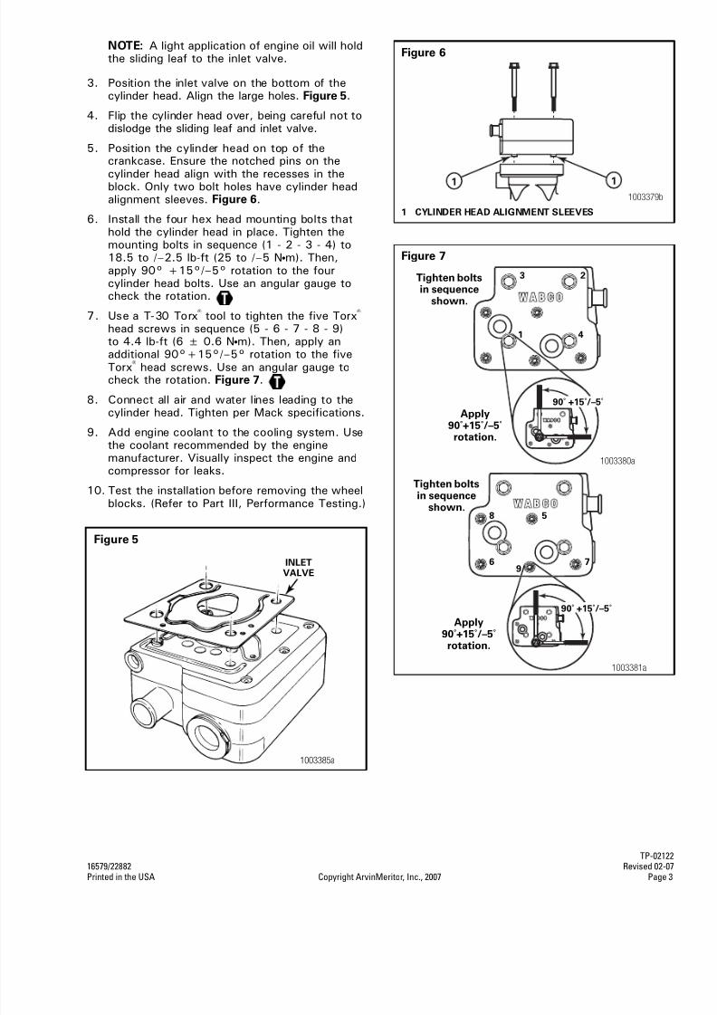
NOTE: A light application of engine oil will holdthe sliding leaf to the inlet valve.
3. Position the inlet valve on the bottom of thecylinder head. Align the large holes. Figure 5.
4. Flip the cylinder head over, being careful not todislodge the sliding leaf and inlet valve.
5. Position the cylinder head on top of thecrankcase. Ensure the notched pins on the
cylinder head align with the recesses in theblock. Only two bolt holes have cylinder headalignment sleeves. Figure 6.
6. Install the four hex head mounting bolts thathold the cylinder head in place. Tighten themounting bolts in sequence (1 - 2 - 3 - 4) to18.5 to /–2.5 lb-ft (25 to /–5 Nm). Then,apply 90° +15°/–5° rotation to the fourcylinder head bolts. Use an angular gauge tocheck the rotation.
7. Use a T-30 Torx® tool to tighten the five Torx® head screws in sequence (5 - 6 - 7 - 8 - 9)to 4.4 lb-ft (6 ± 0.6 Nm). Then, apply an
additional 90°+15°/–5° rotation to the fiveTorx® head screws. Use an angular gauge tocheck the rotation. Figure 7.
8. Connect all air and water lines leading to thecylinder head. Tighten per Mack specifications.
9. Add engine coolant to the cooling system. Usethe coolant recommended by the enginemanufacturer. Visually inspect the engine andcompressor for leaks.
10. Test the installation before removing the wheelblocks. (Refer to Part III, Performance Testing.)
Figure 5
1003385a
INLETVALVE
Figure 6
1 CYLINDER HEAD ALIGNMENT SLEEVES
Figure 7
1 1
1003379b
Tighten boltsin sequence
shown.
Apply90˚+15˚/–5˚rotation.
1 4
3 2
90˚ +15˚/–5˚
1003380a
Tighten boltsin sequence
shown.
Apply90˚+15˚/–5˚rotation.
6 7
8 5
9
90˚ +15˚/–5˚
1003381a

7/27/2019 Compressor Wabco
http://slidepdf.com/reader/full/compressor-wabco 4/6
TP-02122Revised 02-07 16579/22882Page 4 Copyright ArvinMeritor, Inc., 2007 Printed in the USA
II. Compressor Removal and Installation
The front of the Meritor WABCO System Saver 318air compressor is mounted to the engine.
Before you remove the compressor, make sure youhave a replacement gasket to install with the newcompressor (Mack Part Number 590GB2159).Figure 8.
A. Removal
1. Set the spring (parking) brakes and block thewheels of the vehicle.
2. Drain the air pressure from the air system.
3. Drain the engine cooling system and thecylinder head of the compressor.
4. Disconnect all air and water lines leading to thecompressor.
5. Through-drive version air compressor only: Ifthere is a power steering pump installed at theback of the compressor, remove the powersteering pump. Figure 9. Disconnect the powersteering pump. Refer to the manufacturer’s
manual for specific information. It is notnecessary to remove pumps installed at thefront of the compressor.
6. Remove the discharge and coolant fittings.Note fitting locations to aid in assembly.
7. Loosen the three flange mounting bolts thathold the compressor to the engine.
8. Remove the compressor from the vehicle.
Remove and retain the oil supply tube thatruns between the compressor and the engine.Figure 10.
The removal instructions given in thismanual are general. Depending on thetype of vehicle involved, additional stepsmay be required. Refer to the vehiclemanufacturer’s manual for additionalinformation.
Figure 8
1003382a
Figure 9
Figure 10
1003377a
1003378b
OIL
SUPPLY
TUBE
7/27/2019 Compressor Wabco
http://slidepdf.com/reader/full/compressor-wabco 5/6
TP-0212216579/22882 Revised 02-07Printed in the USA Copyright ArvinMeritor, Inc., 2007 Page
B. Installation
1. Reinstall the oil supply tube.
2. Install a new compressor gasket.
3. Position the compressor on the engine.
4. Install the three flange mounting bolts. Tightento 15 lb-ft (20 Nm) +90° rotation.
5. Attach the discharge and coolant fittings.Tighten to 22 lb-ft (30 Nm) +360° maximumto position fitting.
6. Connect all air and water and lines leading tothe compressor. Tighten per Mack specifications.
7. Through-drive version air compressor only: Ifnecessary, reinstall the power steering pump.Refer to the manufacturer’s maintenancemanual to make sure the installation is to theproper specifications.
8. Add engine coolant to the cooling system. Usethe coolant recommended by the enginemanufacturer. Visually inspect the engine andcompressor for leaks.
9. Start the engine and allow air system to buildto governor cutout. Stop the engine. Use asoap and water solution at connection pointsto check for air leaks. Make any necessaryrepairs.
10. Test the installation before removing the wheelblocks. Follow the instructions in Part III,Performance Testing, of this bulletin.
III. Performance Testing
Test the vehicle air system as follows:
1. With wheels blocked and spring (parking)brakes applied, bleed the vehicle air systemreservoir gauges down (apply brakes severaltimes) to approximately 85 psi.
2. With the engine running at full governed speed(no load, no air accessories being used), thecompressor should reach governor cutoutpressure, then unload.
If the compressor does not reach governorcutout pressure, check for air leaks in thesystem. If reservoir volume and engine RPM areper original vehicle manufacturer’s specifications,system plumbing leakage must be checked
and, if necessary, repaired. See air systemleakage test procedures which follow.
If the compressor fails to unload, verify propergovernor operation.
Air System Leakage Test
(Conforms to North American Uniform RoadsideInspection Criteria)
1. Park the vehicle on a level surface. Apply theparking brakes. Disconnect any attached ortowed vehicles (semi-trailer, full trailer, dolly,etc.). Leave engine on.
2. Chock the tires.
3. Release the parking brakes.
4. With the compressor in pumping mode, engineat idle and service brakes fully applied gaugemust stay between 80-90 psi or gradually rise.
If pressure is not maintained (pressure drops)there is an air leak in the system.
Listen for air leaks. Soapy water or highfrequency acoustic detectors may be used todetect any leaks. Make the necessary repairs.

7/27/2019 Compressor Wabco
http://slidepdf.com/reader/full/compressor-wabco 6/6
Meritor WABCO Vehicle Control Systems2135 West Maple RoadTroy, MI 48084-7121 USA800-535-5560meritorwabco.com
Information contained in this publication was in effect at the time the publication was approved forprinting and is subject to change without notice or liability. Meritor WABCO reserves the right to revise the information presented or to discontinue the production of parts described at any time.
Copyright 2007 TP-02122ArvinMeritor, Inc. Revised 02-07All Rights Reserved Printed in USA (16579/22882)