computation of electromagnetic fields
TRANSCRIPT

416 IEEE TRANSACTIONS ON MICROWAVE THEORY AND TECHNIQUES, VOL. MTT-17, NO. 8, AUGUST 1969
Computation of Electromagnetic Fields
ALVIN WEXLER, MEMBER, IEEE
Invited Paper
Abstract—This paper reviews some of the more useful, current and
newly developing methods for the solution of electromagnetic fields. It
begins with an introduction to numerical methods in general, including
specific references to the mathematical tools required for field analysis,
e.g., solution of systems of simultaneous linear equations by direct and
iterative means, the matrix eigenvulue problem, finite difference differ-
entiation and integration, error estimates, and common types of boundary
conditions. This is followed by a description of finite difference solution
of boundary and initial value problems. The paper reviews the mathe-
matical principles behind variational methods, from the Hilbert space
point of view, for both eigenvalue and deterministic problems. The signill-
cance of natural boundary conditions is pointed out. The Rayleigh-Ritz
approach for determining the minimizing sequence is explained, followed
by a brief description of the finite element method. The paper concludes
with an introduction to the techniques and importance of hybrid computa-
tion.
1. INTRODUCTION
W HENEVER ONE devises a mathematical expression
to solve a field quantity, one must be concerned
with numerical analysis, Other than those engineers
involved exclusively in measurements or in the proof of gen-
eral existence theorems or in administration, the remainder
of us are numerical analysts to a degree. Whenever we pre-
scribe a sequence of mathematical operations, we are design-
ing an algorithm. A theory is to us a means of extrapolating
our experiences in order to make predictions. A mathemat-
ical theory, of a physical problem, produces numbers and a
good theory produces accurate numbers easily.
To obtain these numbers, we must employ processes that
produce the required accuracy in a finite number of steps
performed in a finite time upon machines having finite word
length and store. Accepting these constraints we ask how
best to perform under them.
As far as engineers are concerned, there is no principal
difference between analytical and numerical approaches.
Both are concerned with numbers. Oftentimes, the so-called
“analytical” approach—as though to claim inefficiency as a
virtue—is none other than the algorithmically impotent one.
The contrast between efficient and inefficient computation
is emphasized whenever anything beyond the most trivial
work is performed. As an example, consider the solution of a
set of simultaneous, linear equations by Cramer’s rule in
which each unknown is found as a ratio of two determinants.
Manuscript received February 27, 1969; revised May 7, 1969. Thiswork was carried out with financial assistancefrom Atomic Energy ofCanada Ltd. and the National Research Council of Canada.
The author is with the Numerical Applications Group, ElectricalEngineering Department, University of Manitoba, Winnipeg, Man.,Canada.
A moment’s reflection will show that calculating these deter-
minants by evaluating all their cofactors is an insurmount-
able task when the order is not small. Expanding along each
row, n cofactors, each of order n — 1, are involved. Each of
these has cofactors of order n– 2 and so on. Continuing in
this way, we find that at least n! multiplications are needed
to expand the determinant. Neglecting all other operations,
and assuming that the computer does one million multipli-
cations per second, we find that it would take more years
than the universe is old to expand a determinant of order 24.
Even then, due to roundoff errors, the reliability of the result
will be questionable. Cramer’s rule then is surely not a useful
algorithm except for the smallest systems. It is certainly of
the greatest importance in general proofs and existence theo-
rems but is virtually useless for getting numerical answers.
Wilkinson, in a statement referring to the algebraic
eigenvalue problem [25, Preface] said”. . . the problem has
a deceptively simple formulation and the background theory
has been known for many years; yet the determination of
accurate solutions presents a wide variety of challenging
problems.” He would likely agree that the statement applies
equally to most of numerical analysis.
This paper is concerned with the solution of fields by
efficient, current and newly developing, computer practices.
It is intended as an introduction for those totally unfamiliar
with numerical analysis, as well as for those with some ex-
perience in the field. For the sake of consistency, many topics
had to be deleted including numerical conformal mapping,
point matching, mode matching and many others. Propo-
nents of these techniques should not feel slighted as the
author has himself been involved in one of them. In addi-
tion, it was felt advisable to concentrate on general numeri-
cal methods relevant to the microwave engineer, rather than
to review particular problems. Companion papers, in this
special issue, furnish many specific examples.
The principal methods surveyed are those of finite differ-
ences, variational, and hybrid computer techniques. Appro-
priate mathematical concepts and notations are introduced
as an aid to further study of the literature. Some of the refer-ences, found to be the most useful for the author, are classi-
fied and listed in the bibliography.
II. SYSTEMSOF LINEAR EQuArlom
The manipulation and solution of large sets of linear,
simultaneous equations is basic to most of the techniques
employed in computer solution of field problems. These lin-
ear equations are the consequence of certain approxima-
tions made to expedite the solution. For example, approxi-
mation of the operator (Vz, often) over a finite set of points

WEXLER : COMPUTATION OF ELECTROMAGNETIC FIELDS
at which the field is to be computed (as in finite differences),
or approximation of the field estimate (as in variational
methods) causes the problem to be modeled by simultaneous
equations. These equations are conveniently represented by
matrices, It happens, and we shall see why in succeeding sec-
tions, that the finite difference approach creates huge, sparse
matrices of order 5000 to 20000. Sparseness means that there
are very few nonzero elements, perhaps a tenth of one per-
cent. On the other hand, variational methods tend to pro-
duce matrices that are small (typically of order 50), but dense
by comparison.
The size and density of these matrices is of prime impor-
tance in determining how they should be solved. Direct meth-
ods requiring storage of all matrix elements are necessarily
limited to about 150 unknowns in a reasonably large mod-
ern machine. On the other hand, it turns out that iterative
techniques often converge swiftly for sparse matrices. In
addition, if the values and locations of nonzero elements are
easily computed (as occurs with finite differences) there is no
point in storing the large sparse matrix in its entirety. In
such cases, only the solution vector need be stored along
with five nonzero elements (the number produced by many
finite difference schemes) at any stage of the iterative process.
This maneuver allows systems having upto20000 unknowns
to be solved.
This section deals with examples of direct and iterative
techniques for the solution of systems of simultaneous linear
equations. This is followed by a method for solving the
eigenvalue problem in which the entire matrix must be stored
but all eigenvectors and eigenvalues are found at once. Solu-
tion of the eigenvalue problem, by an iterative technique, is
reserved for Section IV where it is more appropriate.
A. Solution by Direct Methods
One of the most popular algorithms for the solution of
systems of linear equations is known as the method of Gauss.
It consists of two parts—elimination (or triangularizution)
and back substitution. The procedure is, in principle, very
simple and is best illustrated by means of an example.
We wish to solve the system
Ax=b (1)
where A is an nX n matrix, x and b are n-element vectors
(column matrices). b is known and x is to be computed.
Consider, for convenience, a small set of equations in three
unknowns xl, x2, and x3,
ZI+4XZ+ X3= 7
ZI+6XZ— x3=13
2XI – Xx + 2x3 = ~.
This example is from [9, pp. 187–188]. Subtract the firstequation from the second of the set.
first from the last. This results in
XI+4ZZ+ X3=
2X2 – 2X3 =
– 9*z + 0Z3 =
Then subtract twice the
7
6
417
The first equation, which was used to clear away the first
column, is known as the pivot equation. The coefficient of the
equation, which was responsible for this clearing operation,
is termed the pivot. Now, the first term of the altered second
equation is made the pivot. Adding
equation to the last, we obtain
XI +4X2+ X3=
2x 2 – 2X: =
– 9X3 =
4.5 times the second
7
6
18.
Clearly, in the computer there is no need to store the equa-
tions as in the preceding sets. In practice, only the numerical
values are stored in matrix form with one vector reserved for
the as yet unknown variables. When the above procedure is
completed, the matrix is said to have been triangularized.
The final step, back substitution, is now initiated. Using
the last equation of the last set, it is a simple matter to solve
for X8= – 2. Substituting the numerical value of X3 into the
second equation, X2= 1 is then easily found. Finally, from
the first equation, we get xl = 5. And so on back through all
the equations in the set, each unknown is computed, one at
a time, whatever the number of equations involved.
It turns out that only n3/3 multiplications are required to
solve a system of n real, linear equations. This is a reasonable
figure and should be compared with the phenomenal amount
of work involved in applying Cramer’s rule directly. In addi-
tion, the method is easy to program.
This simplified account glosses over certain difficulties
that may occasionally occur. If one of the pivots is zero, it is
impossible to employ it in clearing out a column. The cure is
to rearrange the sequence of equations such that the pivot is
nonzero. One can appreciate that even if the pivot is nonzero,
but is very small by comparison with other numbers in its
column, numerical problems will cause error in the solution.
This is due to the fact that most numbers cannot be held
exactly in a limited word-length store. The previous exam-
ple, using integers only, is exceptional. Typically, depending
on the make of machine, computers can hold numbers with
7 to 11 significant digits in single precisioti.
To illustrate the sort of error that can occur, consider the
example, from [15, p. 34]. Imagine that our computer can
hold only three significant digits in j?oating point form. It
does this by storing the three significant digits along with an
exponent of the base 10. The equations
1.00 x 1O-4XI + 1.00Z, = 1.00
1.00X, + 1.0022 = 2.00
are to be solved. Triangularizing, as before, while realizing
the word-length limitation, we obtain
1.00 x lo–%, + 1 .Oox, = 1.00
– 1.00 x 10% = – 1.00 x 10⁴.
Solving for X2 then back-substituting, the computed result
is x.2= 1.00 and xl = 0.00 which is quite incorrect. By the sim-
ple expedient of reversing the order of the equations, we find. .– 9. the result m= 1.00 and ‘xl= 1.00 which is correct to three

418 IEEE TRANSACTIONS ON MICROWAVE THEORY AND TECHNIQUES, AUGUST 1969
significant digits. The rule then is, at any stage of the com-
putation, to select the largest numerical value in the relevant
column as the pivot and to interchange the two equations
accordingly. This procedure is known as a partial pivoting
strategy. Complete pivoting strategy involves the interchange
of columns as well as rows in order to use the numerically
largest number available in the remaining equations as the
pivot. In practice, the results due to this further refinement
do not appear to warrant the additional complications and
computing time.
The previous example suffered from a pure scaling prob-
lem and is easily handled by a pivoting strategy, On the other
hand, except for the eigenvalue problem, nothing can be
done about solving a system of linear equations whose co-
efficient matrix is singular. In the two dimensional case,
singularity (i.e. the vanishing of the coefficient matrix de-
terminant) means that the two lines are parallel. Hence, no
solution exists. A similar situation occurs with parallel
planes or hyperplanes when the order is greater than two. A
well-conditioned system describes hyperplanes that intersect
at nearly 90°. The intersection point (or solution) is relatively
insensitive to roundoff error as a consequence. If hyperplanes
intersect at small angles, roundoff error causes appreciable
motion of the intersection point with a low degree of trust
in the solution. Such systems are termed ill-conditioned.
It is unnecessary, and wasteful, to compute the inverse A–I
in order to solve (l). Occasionally, however, a matrix must
be inverted. This is reasonably easy to accomplish. One of
the simplest methods is to triangularize A, as previously de-
scribed, and then to solve (1) n times using a different right-
hand side b each time. In the first case b should have 1 in its
first element with zeros in the remainder. The 1 should then
appear in the second location for the next back-substitution
sequence, and so on. Each time, the solution gives one col-
umn of the inverted matrix and n back-substitutions produce
the entire inverted matrix. See [12, pp. 32–33 ]. The pro-
cedure is not quite so simple when, as is usually advisable, a
pivoting strategy is employed and when one wishes to tri-
angularize A only once for all n back-substitutions. IBM
supplies a program called MINV which does this, with a
complete pivoting strategy, in an efficient fashion.
Westlake [24, pp. 106-107] reports results of inverting a
matrix of order n= 50 on CDC 6600 and CDC 1604A mac-
hines. Computing times were approximately 0.3 and 17
seconds, respectively. These figures are about double thatpredicted by accounting only for basic arithmetic opera-
tions. The increased time is due to other computer operations
involved and is some function of how well the program was
written. Tests run on the University of Manitoba IBM
360/65 showed that MINV inverts a matrix of order 50 in
3.38 seconds. The matrix elements were random numbers in
the range O to 10.
Note that the determinant of a triangular matrix is simply
the product of the diagonal terms.
The elimination and back-substitution method is easily
adapted to the solution of simultaneous, linear, complex
equations if the computer has a complex arithmetic facility,
as most modern machines do. Failing this, the equations can
be separated into real and imaginary parts and a program
designed for real numbers can then be used. The latter pro-
cedure is undesirable as more store and computing time is
required.
Other inversion algorithms exist, many of which depend
upon particular characteristics of the matrix involved. In
particular, when a matrix is symmetric, the symmetric
Cholesky method [3, pp. 7678 and 95–97] appears to be
the speediest, perhaps twice as fast as Gauss’s method. Under
the above condition, we can write
A=LE (2)
where the tilde denotes transposition. L is a lower triangular
matrix, i.e., nonzero elements occur only along and below
the diagonal as in
111 0 0
[1
L= 121 122 0 . (3)
1,1 132 133
The elements of L may be easily determined by successively
employing the following equations:
all = 1112,a12 = 111121, a13 = 111131,a2.2= 1212+ 1222,(4)
aaa = 121131+ 122132j a33 = 1312 + 1322 + 1332.
Thus, the first equation of (4) gives 111explicitly. Using 111,
the second equation supplies 121,and so on. This operation
is known as triangular decomposition.
The inverse of A is
A-l = ~-1~-l = (L:l)L-I (5)
which requires the inverse of L and one matrix multiplica-
tion. The inverse of a triangular matrix is particularly easy
to obtain by the sequences
lIIZII = 1, 121X11+ 1222’21= o,
231Z11 + Z32$Z1 + Z33X21= o, 122X22= 1, (6)
l,,x,, + 1,3X32= o, 133X33 = 1,
In this way, a symmetric matrix is most economically
inverted.
From (4), it is clear that complex arithmetic may have to
be performed. However, if in addition to being symmetric A
is positive definite as well, we are assured [3, p. 78] that only
real arithmetic is required. In addition, the algorithm is ex-
tremely stable.
B. Solution by Iterative Methods
Iterative methods offer an alternative to the direct meth-
ods of solution previously described. As a typical ith equa-
tion of the system (l), we have
& a,,xj = b<. (7)j=l
Rearranging for the ith unknown
.i=:_~5.j. (8)j=l aitj#i

WEXLER : COMPUTATION OF ELECTROMAGNETIC FIELDS 419
This gives one unknown in terms of the others. The intention
is to be able to make a guess at all variables M and then suc-
cessively correct them, one at a time, as indicated above.
Different strategies are available. One can, for example,
compute revised estimates of all xi using the previously
assumed values. Upon completion of the scan of all equa-
tions, the old values are then overwritten by the new ones.
Intuitively, it seems reasonable to use an updated esti-
mate, just as soon as required, rather than to store it until
the equation scan is completed, With the understanding that
variables are immediately overwritten in computation, we
have
with 1S i< n, m> O. m denotes the iteration count. The two-
part summation indicates that some variables are newly up-
dated. With this method, only n storage locations need be
available for the xl (in comparison with 2n by the previous
system), and convergence to the solution is more rapid
[22, p. 71].
The difference between any two successive xi values cor-
responds to a correction term to be applied in updating the
current estimate. In order to speed convergence, it is possible
to overcorrect at each stage by a factor w Q usually lies be-
tween 1 and 2 and is often altered between successive scans
of the equation set in an attempt to maximize the conver-
gence rate. The iteration form is
(lo)
It turns out that convergence to the solution is guaranteed
if matrix A is symmetric and positive definite [34, pp. 237–
238] and if O< w<2. If m<1 we have underrelaxation, and
ovemelaxation if m>1. This procedure is known as successive
overrelaxation (SOR), there being no point in underrelaxing.
Surprisingly, (10) can be described as a simple matrix
iterative procedure [22, pp. 58–59 ]. By expansion, it is easy
to prove that
(D - @)x@+l) = {(1 - u)D + CJ’}x(n) + cob (11)
where D is a diagonal matrix consisting of the diagonal ele-
ments of A, E consists of the negative of all its elements be-
neath the diagonal with zeros elsewhere, and F is a matrix
having the negative of those elements above the diagonal of,4. Rearranging (11),
X(.+l) = (D _ ~~)–1{(’ _ ~)~ + ~~]x(m)
(12)+ (.o(D – O.E)-%.
Define the matrix accompanying x @’Jas
&. = @ – 6JE)-’{(1– CO)D+ d’]. (13)
&is known as the SOR iteration matrix and plays an impor-
tant role in convergence properties of the method.
The iterative procedure can be rewritten
where c is the last term of (12). Of course, one does not
literally set up &, in order to perform the SOR. process, but
& and (14) express mathematically what happens when the
algorithm described by (10) is implemented.
The process must be stationary when the solution is at-
tained, i.e., x(~+l) = x(~) =x. Therefore, we must have that
c = (1 — $.)x. (15)
Substitute (15) into (14) and rearrange to obtain
X(m+l) — x==J30(xbfd — x). (16)
These terms are clearly error vectors as they consist of ele-
ments giving the difference between exact and computed val-
ues. At the mth iteration, the form is
~(m) = ~(m) — ~. (17)
Therefore (16) becomes
~(m+l) = &@8 (m) = &@28(m–1)
(18). ..= &m+18(o)
due to the recursive definition of (16). It is therefore clear
that the error tends to vanish when matrix& tends to vanish
with exponentiation. It can be proved [22, pp. 13–15 ] that
any matrix A raised to a power r vanishes as r-+ co if and
only if each eigenvalue of the matrix is of absolute value less
than one. It is easy to demonstrate this for the special case
of a real, nonsymmetric matrix with distinct eigenvalues. We
cannot be sure that & (which is not symmetric in general)
has only distinct eigenvalues, but we will assume this for pur-
poses of illustration. In this case all eigenvectors are linearly
independent. Therefore, any arbitrary error vector & may
be expressed as a linear combination of eigenvectors 1; of
&@,i.e.,
~ = alll + a212 + . . “ + d.. (19)
If the eigenvectors are known, the unknown ai may be found
by solving a system of simultaneous linear equations. As the
Ii are linearly independent, the square matrix consisting of
elements of all the Ii has an inverse, and so a solution must
exist.
Performing the recursive operations defined by (18), we
obtain
where pi is the eigenvalue of.& corresponding to the eigen-
vector Ii. It is obvious, from (20), that if all eigenvalues of& are numerically less than unity, SOR will converge to the
solution of(l). In the literature, the magnitude of the largest
eigenvalue is known as the spectral radius p(&J.
It is also easily shown that the displacement vector 5,
which states the difference between two successive x esti-
mates, can replace s in (18>(20).
A sufficient, although often overly stringent condition, for

420 IEEE TRANSACTIONS ON MICROWAVE THEORY AND TECHNIQUES, AUGUST 1969
the convergence of SOR is that the coefficient matrix A dis-
play diagonal dominance. This occurs if, in each row of A,
the sum of the absolute values of all off-diagonal terms is
greater than the absolute value of the diagonal term itself.
In practice, we are concerned not only with whether or not
convergence will occur, but also with its speed. Equation (20)
indicates that the smaller the spectral radius of&, the more
rapidly convergence occurs. As indicated by the subscript,
.& and its eigenvalues are some function of the acceleration
factor u. The relationship between coand the spectral radius
P(SJ is a very complicated one and so only very rarely can
the optimum acceleration factor uoPt be predicted in ad-
vance. However, some useful schemes exist for successively
approximating uoP~ as computation proceeds (see [14],
[15], [17]-[20]).
To conclude, the main advantage of SOR is that it is un-
necessary to store zero elements of the square matrix as is
required by many direct methods. This is of prime impor-
tance for the solution of difference equations which require
only the vector to be stored. Also, the iteration procedure
tends to be self-correcting and so roundoff errors are some-
what restricted. There are direct methods that economize on
empty matrix elements, but SOR is perhaps the easiest way
to accomplish this end.
C. The Matrix Eigenvalue Problem
The general matrix eigenvalue problem is of the form
(A – AB)X = o (21)
where A and B are square matrices. This is the form that re-
sults from a variational solution (see Section V). The prob-
lem is to find eigenvalues x and associated eigenvectors x
such that (21) holds. This represents a system of linear,
homogeneous equations and so a solution can exist only if
determinant of (A – MI) vanishes. If A and B are known
matrices, then a solution can exist only for values of A which
make the determinant vanish. Eigenvectors can be found that
correspond to this set of eigenvalues. It is not a practical
proposition to find the eigenvalues simply by assuming trial
A values and evaluating the determinant each time until it is
found to vanish. Such a procedure is hopelessly inefficient.
An algorithm for matrices that are small enough to be
held entirely in the fast store (perhaps n = 100) is the Jacobi
method for real, symmetric matrices. Although it is not a
very efficient method, it is fairly easy to program and servesas an example of a class of methods relying upon symmetry
and rotations to secure the solution of the eigensystem.
If B= 1, the unit matrix, (21) becomes
(A – AI)X = o (22)
which is the form obtained by finite difference methods. If
A can be stored in the computer, and if A is symmetric as
well, a method using matrix rotations would be used. Equa-
tion (21) may not be put into this form, with symmetry pre-
served, simply by premultiplying by B–l. The product of two
symmetric matrices is not in general symmetric. However, if
we know that B is symmetric and positive definite, triangular
decomposition (as described in Section II-B) may be em-
ployed using only real arithmetic. Therefore
where
C = L-lAZ-l.
[23)
(24)
Note that ~ equals C and so it is symmetric.
Taking the determinant of both sides of (23),
det (A – hB) = det (L)’ det (C – Al). (25)
Since det (L) is nonzero, we can see that eigenvalues of A
are those of C. Therefore, instead of (21), we can solve the
eigenvalue problem
(c – M)y=o (26)
where
y = Zx. (27)
We therefore obtain the required eigenvalues by solving (26).
Eigenvectors y are easily transformed to the required x by
inverting ~ in (27).
Orthogonal matrices are basic to Jacobi’s method. A
matrix T is orthogonal if
If T consists of real elements, it is orthogonal if the sum of
the squares of the elements of each column equals one and
if the sum of the products of corresponding elements in two
different columns vanishes. One example is the unit matrix
and another is
[
Cos +T=
— sin @
sin @ 1Cos+- (29)
Matrix (29) can be inserted in an otherwise unit matrix such
that the cos @terms occur along the diagonal. This is also an
orthogonal matrix and we shall denote it T as well.
Since the determinant of a product of several matrices
equals the product of the determinants, we can see from (28)
that det (T)= 1 or – 1. Therefore
det (A – M) = det (T(A – M) ~)
= det (T.4 ~ – U)(30)
and so the eigenvalues of A and TAT are the same.It is possible to so position (29) in any larger unit matrix,
and to fix a value of @, such that the transformed matrix
TAT has zeros in any chosen pair of symmetrically placed
elements. Usually one chooses to do this to the pair of ele-
ments having the largest absolute values. In doing this, cer-
tain other elements are altered as well. The procedure is re-
peated successively with the effect that all off-diagonal terms
gradually vanish leaving a diagonal matrix. The elements of
a diagonal matrix are the eigenvalues and so these are all
given simultaneously. It is possible to calculate the maximum
error of the eigenvalues at any stage of the process and so to
terminate the operation when sufficient accuracy is guar-
anteed. The product of all the transformation matrices is

WEXLER : COMPUTATION OF ELECTROMAGNETIC FIELDS 421
continuously computed. The columns of this matrix are the
eigenvectors of A. See [3, pp. 109–1 12] and [7, pp. 129-131].
Probably the most efficient procedure, in both storage and
time, is that due to Householder. It is described by Wilkin-
son [26] and, in a very readable form, by Walden [23].
A method, employing SOR for large sparse matrices, is
described in Section IV,
III. FINITE DIFFERENCES
The importance of finite differences lies in the ease with
which many logically complicated operations and functions
may be discretized. Operations are then performed not upon
continuous functions but rather, approximately, in terms of
values over a discrete point set. It is hoped that as the dis-
tance between points is made sufficiently small, the approxi-
mation becomes increasingly accurate. The great advantage
of this approach is that operations, such as differentiation
and integration, may be reduced to simple arithmetic forms
and can then be conveniently programmed for automatic
digital computation. In short, complexity is exchanged for
labor.
A. Di&erentiation
First of all, consider differentiation. The analytic approach
often requires much logical subtlety and algebraic innova-
tion. The numerical method, on the other hand, is very direct
and simple in principle. However, implementation in many
instances presents problems of specific kinds.
Consistent with a frequent finite difference notation, a
function~ evaluated at any x is often written~(x) =f,. At a
point, distance h to the right f’(x+k) =f,+~. To the left we
have f~_~, f~_,~, etc. Alternatively, nodes (or pivotal points)
are numbered i yielding function values f ~,f i+l$ f i–l, etc. It is
understood that the distance between nodes is h and node i
corresponds to a particular x. Refer to Fig. 1. The derivative
f:= g/dx, at any specified x, may be approximated by theforward dl~erence formula
~, = .fz+h – f.x
h(31)
where the function is evaluated explicitly at these two points.
This, for very small h, corresponds to our intuitive notion of
a derivative. Equally, the derivative maybe expressed by the
backward dl~erence formula
(32)
These are, in general, not equal. The first, in our example,
gives a low value and the second a high value. We can there-
fore expec+ the average value
(33)
to give a closer estimate. This expression is the central dzjfer-
ence formula for the first derivative. In the figure, we see that
the forward and backward differences give slopes of chords
on alternate sides of the point being considered. The central
f(x)
I
fx.h I
fi.1 Ifx ‘
I $1 fx*I
‘i+l1x-h x-h/2 X X+h/Z x+h xl-l i-1/2 i i +l/2 i+l I
Fig. 1. Forward, backward, and central differences.
difference, given by the slope of the chord passing through
fzfh and f.-,, certainly appears to approximate the true de-rivative most closely. Usually, this is so. Forward and back-
ward difference formulas are required to compute derivatives
at extreme ends of series of tabulated data. The central dif-
ference formula is preferred and should be used if data are
available on both sides of the point being considered.
An idea of the accuracy of (31}(33) is obtained from a
Taylor’s expansion at x+h. This gives
Similarly, at x– h
Subtractingfz from (34), then rearranging, gives
O(h) means that the leading correction term deleted from this
forward difference derivative approximation is of order h.
Similarly, from (35), the backward difference formula can
be seen to be of order h as well.
Subtracting (35) from (34), and rearranging, we obtain
f: = (f.+}’ – fz-,)/2h – ~h2fJ” + .-.
= (fm+h– f.-h)/2h + O(h’)(37)
which is the central difference formula (33) with a leading
error term or order hz. Assuming that derivatives are well
behaved, we can consider that the h’ term is almost the sole
source of error. We see that decreasing the interval resultsin higher accuracy, as would be expected. In addition, we see
that the error decreases quadratically for the central differ-
ence derivative and only linearly for the forward or back-
ward difference ones.
Only two of the three pivotal points shown in Fig. 1 were
needed for evaluating the first derivative. Using the three
available pivots, a second derivative maybe computed. Con-

422 IEEE TRANSACTIONS ON MICROWAVE THEORY AND TECHNIQUES, AUGUST 1969
sider the derivative at x+h/2. Using central differences, with
half the previous interval,
.f~+hiz = (f~+~ – ~S)/h. (38)
Similarly,
f;-h/z = (.fz – j#t)/ii (39)
giving the values of the first derivative at two points distance
h apart. The second derivative at x is then
(40)
= (fcc+h– 3.+ f.-it)/h2
in which (33) has been applied with (38) and (39) supplying
two first derivative values. By adding (34) and (35), (40) may
be derived with the additional information that the error is
of order hz.
Another point of view for understanding finite difference
differentiation is the following. Assume that a parabola
f(z) = az’ + bx + c (41)
is passed through the three points f.–h, f., and fz+h of Fig. 1.
For simplicity let x= O. Evaluating (41) at x= – h, O, and h,
we easily find that
a = (f~ – 2~0 + f–h) /2h2, (42)
b = (fh – f-h)/2k (43)
and
c = fo. (44)
Differentiating (41), then setting x= O, we find we get the
same forms as (33) and (40) for the first and second deriva-
tives. Thus, differentiation of functions specified by discrete
data is performed by fitting a polynomial (either explicitly
or implicitly) to the data and then differentiating the poly-
nomial. It is clear then that an nth derivative of a function
can be obtained only if at least n+ 1 data points are avail-
able. A word of warning—this cannot be pursued to very
high orders if the data is not overly accurate. A high-order
polynomial, made to fit a large number of approximate data
points, may experience severe undulations. Under such cir-
cumstances, the derivative will be unreliable due to higher
order terms of the Taylor series. Also note that accuracy of
a numerical differentiation cannot be indefinitely increased
by decreasing h, even if the function can be evaluated at anyrequired point. Differentiation involves differences of num-
bers that are ahnost equal over small intervals. Due to this
cause, roundoff error may become significant and so the
lower limit to h is set largely by the computer word length.
Bearing in mind that high-order polynomials can cause
trouble, some increase in accuracy is possible by using more
than the minimum number of pivots required for a given
derivative. For example, as an alternative to (40), the second
derivative can be obtained from
f~’ = (–f.-z~+ 16f.-~– 30f.+ 16f.+h–f.r+m)/12h’ (45)
with an error of 0(h4).
Not always are evenly spaced pivotal points available.
Finite difference derivative operators are available for such
Y
I
Ii,j+l
h
I
‘-’--f--ih
1 i,j-1
x
Fig. 2. Five point, finite difference operator.
cases as well. This is obvious as approximating polynomials
can be fitted to data not equispaced. For example, if pivots
exist at x— h, x, and x+ ah (where a is a real number), an
appropriate derivative expression is
f:! = 2(af~-~ – (1 + a)f~ + f~+~) (46)
C& + l)h2
which is identical to (40) when a= 1. However, if a# 1, (46)
and other differentiation equations for unsymmetric pivots
have reduced accuracy.
The preceding, and many other differentiation expressions,
are given in [12, pp. 64-87]. For instance, since numerical
differentiation involves the determination and subsequent
differentiation of an interpolating polynomial, there is no
reason that the derivative need be restricted to pivotal
points.
Finally, the most important derivative operator for our
purposes is the Laplacian V2. In two dimensions it becomes
V?. Acting upon a potential 4(x, y) we have
(47)
where x and y are Cartesian coordinates. Using a double
subscript index convention, and applying (40) for each
coordinate, the finite difference representation of (47) is
Fig. 2 illustrates this five point, finite difference operator
which is appropriate for equispaced data. Often it is neces-sary to space one or more of the nodes irregularly. This is
done in the same fashion employed in the derivation of (46)
[12, pp. 231-234]. Finite difference Laplacian operators are
also available in many coordinate systems other than the
Cartesian. For example, see [12, pp. 237-252].
B. Integration
Numerical integration is used whenever a function cannot
easily be integrated in closed form or when the function is
described by discrete data. The principle behind the usual
method is to fit a polynomial to several adjacent points and
integrate the polynomial analytically.
Refer to Fig. 3 in which the function f(x) is expressed by
data at n equispaced nodes. The most obvious integration

WEXLER : COMPUTATION OF ELECTROMAGNETIC FIELDS
f(x
i-1 i i-1 i i+lx
Fig. 3, Integration under the curvej(x). Trapezoidal rule for a singlestrip and Simpson’s 1/3 rule for pairs of strips.
formula results by assuming that the function~(x) consists of
piecewise-linear sections. Each of these subareas is easily
computed through
where x; is the value of x at the ith pivot. The total area is
found by summing all A;. Equation (49) is the trapezoidal
rule for approximating the area under one strip with error of
order hs.The trapezoidal formula (49) may be applied, sequentially,
to a large number of strips. In this way we obtain
which has a remainder of order h2. The decrease in accuracy,
compared with the single-strip case, is due to error accu-
mulated by adding all the constituent subareas.
A more accurate formula (and perhaps the most popular
one) is Simpson’s * rule
(51).5
which, by using a parabola, approximates the integral over
two strips to 0(h5). If the interval (a, b) is divided into an
even number of strips, (51) can be applied at each pair in
turn. Therefore
Jbf(z)dz e : (f, + 4fl + 2f2 + 4f3 + “ “ “n (52)
+ 2fn-, + 4fn_, + f.)
with an error of 0(h4). Another Simpson’s formula, known
as the ~ rule (because the factor % appears in it), integrates
groups of three strips with the same accuracy as the $ rule.
Thus, the two Simpson’s rules may be used together to cater
for an odd number of strips.
By and large, integration is a more reliable process than
differentiation, as the error in integrating an approximating
polynomial tends to average out over the interval.
error i\i\
I\\1
423
/’/
i’,’
I ‘! /’\ /\\ /’1$
t’! 1’\\ /)I\ /’
“d
\ ,!\\
11\\ ,r/\\\ ,/’
‘\ //’‘\ total
round-off’. error ,Z’dkcretizotionerror ‘.
‘. /“ error,/==
I .;’- -.----- ------------ ---__...---
mesh intervol h
Fig. 4. Error as a function of mesh interval.
It is not possible to indefinitely reduce h with the expecta-
tion of increased accuracy. Although smaller intervals reduce
the discretization error, the increased arithmetic causes
larger roundoff error. A point is reached where minimum
total error occurs for any particular algorithm using any
given word length. This is indicated in Fig. 4.
Highly accurate numerical integration procedures are pro-
vided by Gauss’ quadrature formulas [7, pp. 3 12–367].
Rather than using predetermined pivot positions, this
method chooses them in order to minimize the error. As a
result, it can only be used when the integrand is an explicit
function.
Multiple integration [12, pp. 198–206] is, in theory, a
simple extension of one-dimensional integration. In practice,
beyond double or triple integration the procedure becomes
very time consuming and cumbersome.
To integrate
bdv= H f.,uclxdy (53)
ac
over the specified limits, the region is subdivided (see Fig.
5(a)). As one would expect, to perform a double integration
by the trapezoidal rule, two applications of (49) are required
for each elemental region. Integrating along x, over the ele-
ment shown, we obtain
hgj = ~ (fi,j + .fi+l!J (54)
h
9j+l = ~ Ui!,+l + fi+l!j+l). (55)
It now remains to perform the integration
which results from two applications of the trapezoidal rule,

424 IEEE TRANSACTIONS ON MICROWAVE THEORY AND TECHNIQUES, AUGUST 1969
i,j+l i+l, j+l
; ~hff(x,y)dxdy
ni ,j i+l, j
(a)
w“+’W“’;f[f(x’y)dxdy
‘1 -’”-’I
x
(b)
Fig. 5. Double integration molecules. (a) Trapezoidal rule.(b) Simpson’s 1/3 rule.
Similarly, three applications of Simpson’s ~ rule produce
V = ~ { 16j’;,j -1- 4(fi,j-1 + .ft+I,~ + .f’i,j+I + fi-1,~)
+ .fi+l,i-l + .ft+l,f+l + ,fi-l,i+l + J“.t-1,+1 }
(57)
which gives the double integral off. ,Vover the elemental two
dimensional region of Fig. 5(b). Molecules in the figure
illustrate the algorithm,
IV. FINITE DIFFERENCE SOLUTION OF
PARTIAL DIFFERENTIAL EQUATIONS
The finite difference technique is perhaps the most pop-
ular numerical method for the solution of ordinary and
partial differential equations. In the first place, the differen-
tial equation is transformed into a difference equation by
methods described in Section III. The approximate solution
to the continuous problem is then found either by solving
large systems of simultaneous linear equations for the
deterministic problem or by solving the algebraic eigenvalue
problem as outlined in Section II. From the point of view
of fields, the resulting solution is then usually a potential
function @ defined at a finite number of points rather than
continuously over the region.
A. Boundary Conditions
The most frequently occurring boundary conditions are of
several, very general forms. Consider, first of all, the Dirich-
Iet boundary condition defined by
0(s) = g(s) (58)
which states the values of potential at all points or along any
number of segments of the boundary. See Fig. 6 which
represents a general two-dimensional region, part of it obey-
ing (58). If we visualize this region as a sheet of resistive
material, with surface resistivity r, the Dirichlet border is
simply one maintained at a potential g(s). At ground poten-
tial, g(s) = O which is the homogeneous Dirichlet boundary
condition.
Dirichlet boundary
&%:&
I mn ‘:Po rs
e t
‘\ +-t.... .,....
---.--%----~ kouchy----- boundary
Neunmnnboundary 3$
%’ l:~’’’-’’’’---------”’’q(s)(d+(d’q(s)Fig. 6. A mixed boundary value problem.
The Neumann boundary condition
(59)
is also easy to interpret physically. Imagine current to be
forced into the region, from across the boundary, at a rate
independent of the potential. A large number of constant
current sources, strung along the boundary, would simulate
this effect. The normal, linear current flow density is – in(s),
the negative sign signifying a flow direction in a sense oppo-
site to the unit normal. The surface resistivity r divided into
the normal electric field strength at the boundary t@/&z \,—— —in(s), i.e., (1/r)/(&j/&z) 1, = —in(s). Another analogy is
the flux emanating from a distributed sheet of charge backed
by a conductor. In general then, the Neumann boundary
condition is written as in (59). Along an impermeable border,
an open circuit in Fig. 6, p(s)= O.
The remaining boundary condition, of concern to us, is
the Cauchy (or third) condition. Imagine that the border is
a film offering resistance R to current flowing across it. Such
a film occurs in heat transfer between, say, a metal and a
fluid. A series of resistors strung out across the boundary
would simulate such an effect. Let the potential just outside
the conducting region be ~O(s), a function of position along
the curve. The potential just inside is $(s) and so the linear
current density transferred across is iJs) = (+(s) – dO(s))/R
where R is the film resistance. Since (l/r)/(d@/iIn)]. = – i.(s),
we have by eliminating i.(s), (R/r)/(E@/&z) 1,+d(s) = +.(s).
In general, this is written
C3(j-& + a(s)cj(s) = q(s).
s(60)
A harmonic wave function 4, propagating into an infinite
region in the z direction, obeys &p/8z = –jp~ or &$/dz+j@$
= O at any plane perpendicular to z. This is a homogeneous
case of (60).
A region having two or more types of boundary conditions
is considered to constitute a mixed problem.
B. D@erence Equations of the Elliptic Problem
Second-order partial differential equations are conve-
niently classified as elliptic, parabolic, and hyperbolic [12,
pp. 190-191 ]. Under the elliptic class fall Laplace’s, Poisson’s,
WEXLER : COMPUTATION OF ELECTROMAGNT3TIC FIELDS
and the Helmholtz partial differential equations. By way of
illustration, we will now consider the first and last ones.
Fig. 6 shows several five-point operators in somewhat
typical environments. To be specific, consider the discretiza-
tion of Laplace’s equation
V%j = o (61)
consistent with the applied boundary conditions. From (48),
(61) becomes
+a+@%–@c+$d+&=O. (62)
A reasonably fine mesh results in a majority of equations
having the form of (62). The trouble occurs in writing finite
difference expressions near the boundaries. Near the Dirich-
Iet wall we have Of= g(sl) where SI denotes a particular point
on s. Making this substitution, the finite difference expres-
sion about node h is
+, –4r#J/, +@i+@lj=-gf (63)
where S1and nodef coincide. Along the Neumann boundary,
(59) must be satisfied. To simplify matters for illustration,
the five-point operator is located along a flat portion of the
wall. Using the central difference formula (33), (59) becomes
.
–410100
1–4 1 0 1 0
0 1–4 o 0 1
1 0 o–4 1 0
01 01–41
0010 1 –4
000 100
000010
(4~–&)/2h =p~. This equation can then be used to eliminatenode 1 from the difference equation written about node m.
Therefore
~~ – @., + 26. + @o= – 2hpm. (64)
Finally, at the Cauchy boundary, (4. – 4J/2h+ u,& = q,
which makes the node r difference equation
& + 24, – 4(1 + urhi~)or + @ = – 2hg,. (65)
SOR is employed to solve for each node potential in terms
of all other potentials in any given equation. As there are at
most five potentials per equation, each node is therefore
written in terms of its immediately adjacent potentials. In
other words, it is the central node potential of each operator
that is altered in the iterative process. As all points on aDirichlet boundary must maintain fixed potentials, no
operator is centered there. This does not apply to Neumann
and Cauchy boundaries, however, and so potentials on these
walls must be computed.
It is no mean feat to program the logic for boundaries
(particularly non-Dirichlet ones) which do not correspond
to mesh lines, and this is one of the major drawbacks of the
finite difference approach. The literature gives a number of
425
4(s) =V.-,
Fig. 7. Finite difference mesh for solution of Laplace’s equation underDirichlet boundary conditions.
appropriate schemes. See for example [28], (34, pp. 198–
204] , [35, pp. 262-266], [37, pp. 36-42].
In reference [27] a simple, although somewhat inaccurate,
method for fitting an arbitrary shape is given. For simplicity,
the boundary was permitted to deform, at each horizontal
mesh level, to the nearest node point.
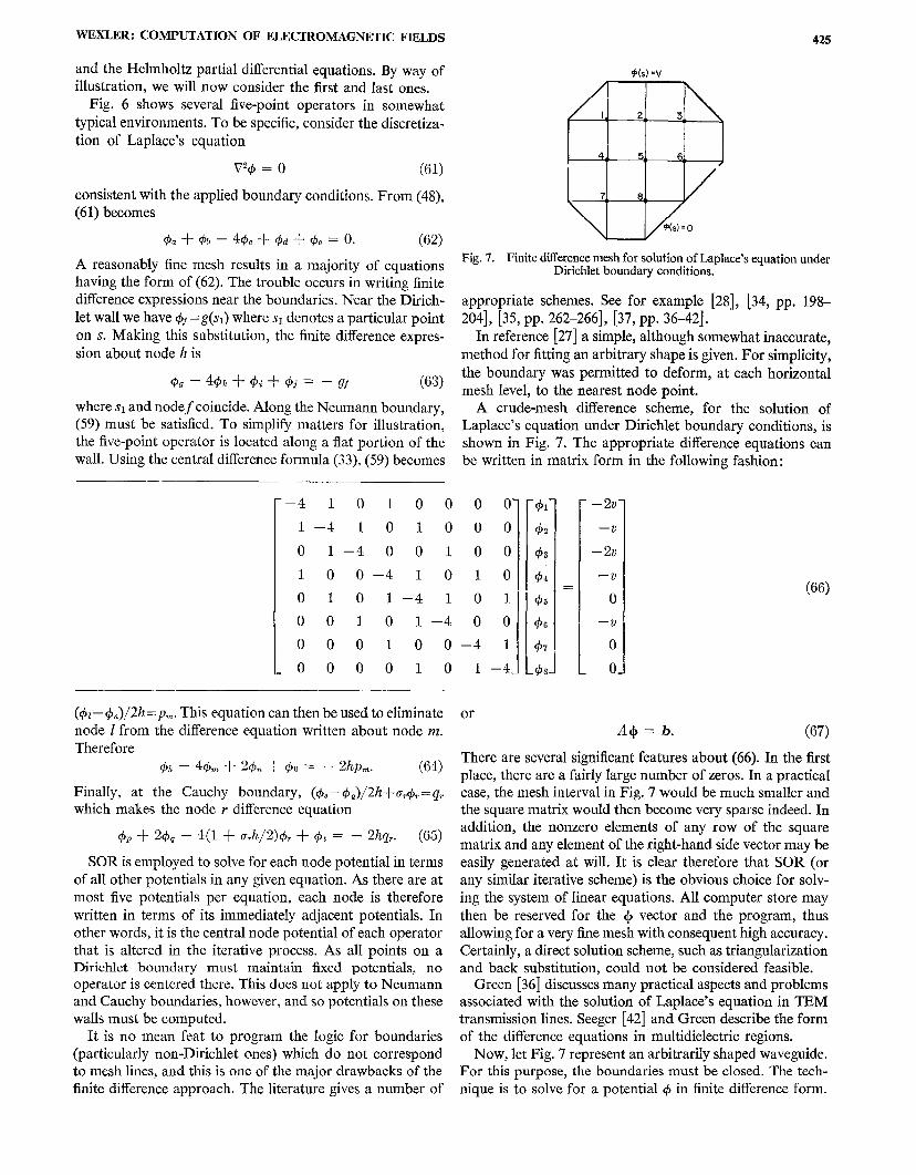
A crude-mesh difference scheme, for the solution of
Laplace’s equation under Dirichlet boundary conditions, is
shown in Fig. 7. The appropriate difference equations can
be written in matrix form in the following fashion:
o 0-
00
00
10
01
00
–4 1
1 –4.
or
.
– 2V
—v
– 2V
—v
o
—v I
o
01
(66)
A+ = b. (67)
There are several significant features about (66). In the first
place, there are a fairly large number of zeros. In a practical
case, the mesh interval in Fig. 7 would be much smaller and
the square matrix would then become very sparse indeed. In
addition, the nonzero elements of any row of the square
matrix and any element of the right-hand side vector maybe
easily generated at will. It is clear therefore that SOR (or
any similar iterative scheme) is the obvious choice for solv-
ing the system of linear equations. All computer store may
then be reserved for the ~ vector and the program, thus
allowing for a very fine mesh with consequent high accuracy.
Certainly, a direct solution scheme, such as triangularization
and back substitution, could not be considered feasible.Green [36] discusses many practical aspects and problems
associated with the solution of Laplace’s equation in TEM
transmission lines. Seeger [42] and Green describe the form
of the difference equations in multidielectric regions.
Now, let Fig. 7 represent an arbitrarily shaped waveguide.For this purpose, the boundaries must be closed. The tech-
nique is to solve for a potential @ in finite difference form.

426 IEEE TRANSACTIONS ON MICROWAVE THEORY AND TECHNIQUES, AUGUST 1969
If z is along the axial direction, z&+ is proportional to E, or
H. depending on whether TM or TE modes are being con-
sidered. For TM modes the boundary condition is the
homogeneous Dirichlet one (58), i.e., with g(s)= O. Fields
are then derived from
Z= +,4c
H,=O
if E, is made eaual to d. Likewise, the homogeneous
(68)
Neu-.mann condition (59) (with p(s)= O) applies to TE modes,
with fields obtainable from
Ez=O(69)
Hz = 4.
k, is the cutoff wavenumber and Y the propagation constant.
Of course, one does not solve for@ but rather for +, a vector
of discrete potentials, and so the differentiations indicated
by (68) and (69) must be performed by techniques outlined
in Section III-A.
Discretization of the Hehnholtz equation
(v,’ + k.’)d = o (70)
produces a matrix eigenvalue problem of the form
(A – AI)+ = o. (71)
About a typical internal node such as 5 in Fig. 7, the finite
difference form of (70) is
‘@z–@4+ (4– A)@5–@6– @8=0 (72)
where
A = (l:ch) ‘. (73)
Equations such as (72), suitably amended for boundary con-ditions, make up the set expressedby(71). Signs are changedin (72) to make, as is the frequent convention, the matrix
positive semidefinite rather than negative semidefinite.
Successive overrelaxation can be used to solve the matrix
eigenvalue problem (71). In the first place a fairly crude
mesh, with perhaps 50-100 nodes, is “drawn” over the guide
cross section. A guess at the lowest eigenvalue (either an
educated one or perhaps the result of a direct method on an
even coarser mesh) is taken as a first approximation. Theelements of vector @are set to some value, perhaps all unity.
SOR is then initiated generating only one row at a time of
A – AZ as required. A nontrivial solution of (A – A&$ canexist only if the determinant vanishes, i.e., the guess at k is
a true eigenvalue. In general, the 1 estimate will be in error
and so ~ cannot be found by SOR alone and an outer
iteration employing the Rayleigh quotient (defined later)
must be employed.
Application of SOR to a homogeneous set of equations
causes (14) to assume the form
+(m+l) = &@,A+(m). (74)
The subscript A has been added to the iteration matrix to
indicate a further functional dependence. As in Section II-B,
for illustration, assume that J&,l is a real (generally non-
symmetric) matrix with distinct eigenvalues. Then, @(~)
may be expressed as a linear combination of eigenvectors of
&,i, i.e.,
~(m) = alll + u,l, + . . . + al.. (75)
Iterating through (74)s times, we find that
+(m+.) = a w1’11 + awflz -1- . “ “ -t- anp~’1~. (76)
If KI is the eigenvalue having the greatest absolute value,
then ifs is large, we have substantially that
+(~+s) = alpls~l. (77)
Equation (74) must represent a stationary process when SOR
has converged and so ~, = 1 at the solution point. It is inter-
esting to note that the eigenvector 21of $ti,x is, or is propor-
tional to, the required eigenvector of A when the correct k
is substituted into (71).
Rewrite (71) as
B$=O (78)
where
B=.4– AI (79)
with an assumed or computed A approximation. The con-
vergence theorem [34, p. 240] states that if B is symmetric
and positive semidefinite, with all diagonal terms greater
than zero (which can always be arranged unless one of them
vanishes), and if the correct k is employed, then the method
of successive displacements (SOR with u = 1) converges to
the solution whatever @ is initially. It will also converge
[34, pp. 260-262] for 0<0<2 if the elements b~j=bi,SO
(i#j) and b,,> O.
As will usually happen, an eigenvalue estimate will not be
correct. If it deviates from the exact eigenvalue by a smallamount we can expect PI, in (77), to be slightly greater than
or less than unity. Therefore +(~+sl will grow or diminish
slowly as SOR iteration proceeds, It cannot converge to a
solution as B is nonsingular. (B is termed singular if its
determinant vanishes.) However, the important point is that
whether @tends to vanish or grow without limit, its elements
tend to assume the correct relative values. In other words,
the “shape” of 1$converges to the correct one. After several
SOR iterations the approximate @ is substituted into the
Rayleigh quotient [35, pp. 74-75]
(80)

WEXLER : COMPUTATION OF ELECTROMAGNETIC FIELDS 427
Equation (80), which depends only upon the “shape” of +,
is stationary about the solution point. In other words, Z~~
is a reasonable estimate to the eigenvector then (80) pro-
duces an improved eigenvalue estimate. The bracketed
superscripts give the number of the successive eigenvalue
estimate and are therefore used in a different context from
that in (74). Using the new eigenvalue approximation, and
returning to the SOR process with the most recent field esti-
mate, a second and better estimate to @is found, and so on
until sufficient accuracy is obtained. Whether or not con-
vergence has been achieved may be gauged firstly by observ-
ing the percentage change in two or more successive eigen-
value estimates. If the change is considered satisfactory, per-
haps less than one-tenth of a percent, then the displacement
norm as a percentage of the vector norm should be inspected.
(The norm of a column matrix is often defined as the square
root of the sum of squares of all elements.) When this is
within satisfactory limits, the process may be terminated.
These requirements must be compatible in that one cannot
expect the displacement norm to be very small if the eigen-
value estimate is very inaccurate. What constitutes sufficient
stationarity of the process is largely a matter of practical
experience with the particular problem at hand and no gen-
eral rule can be given. This entire computing procedure,
including a optimization, is described in [34, pp. 375-376]
and [38, pp. 114-129]. Moler [38] points out that no proof
exists guaranteeing convergence with the Rayleigh quotient
in the outer loop. However, experience indicates that with a
reasonable A estimate to begin with, and with other condi-
tions satisfied, we can be fairly confident.
Generally, the higher the accuracy required, the smaller
the mesh interval and the larger the number of equations to
be solved. The number of eigenvalues of Qti,x equals the
order of the matrix and a large number of eigenvalues means
that they are closely packed together. It is therefore clear,
from (76), that if the dominant and subdominant eigenvalues
of $. ,A(Y1 and wZ)are nearly equal, the process (74) will need
a great number of iterations before the dominant eigenvector
“shape” emerges. In fact, successive overrelaxation correc-
tions could be so small that roundoff errors destroy the
entire process and convergence never occurs. The answer is
to start off with a crude mesh having, perhaps, one hundred
nodes in the guide cross section. Solve that matrix eigenvalue
problem, halve the mesh interval, interpolate (quadratically
in two dimensions, preferably) for the newly defined node
potentials, and then continue the process. The rational
behind this approach is that each iterative stage (other than
the first) begins with a highly accurate field estimate and so
few iterations are required for the fine meshes. For arbitrary
boundaries, programming for mesh halving and interpola-
tion can be an onerous chore.As one additional point, the effect of Neumann boundary
conditions is to make B slightly nonsymmetric and so con-
vergence of the SOR process cannot be guaranteed. This
occasionally causes iteration to behave erratically, and some-
times fail, for coarse meshes in which the asymmetry is most
pronounced. Otherwise, the behaviour of such almost sym-
metric matrices is similar to that of symmetric ones. The
most convenient way to guarantee symmetric matrices is to
employ variational methods in deriving difference equations
near boundaries. Forsythe and Wasow [34, pp. 182–1 84]
give a good account of this approach.
When the solution for the first mode is obtained,
det (B)= O with the correct A substituted into (79). If one
then wanted to solve for a higher mode, a new and greater A
estimate would be used, If this differs from the first by a, this
is equivalent to subtracting a from all diagonal terms of B,
Now, if p is any eigenvalue of B, then
B+ = p~. (81)
Subtracting aI from both sides,
(1? – al)+ = (p – a)+ (s~)
we see that all eigenvalues of the new matrix (B– al) are
shifted to the left by a units. Since B had a zero eigenvalue,
at least one eigenvalue must now be negative. A symmetric
matrix is positive definite if and only if all of its eigenvalues
are positive [16, p. 105] and positive semidefinite if all are
nonnegative. Therefore, (B— aZ) is not positive semidefinite
and so the convergence theorem is violated. Consequently,
the previous SOR scheme cannot be employed for modes
higher than the first.
Davies and Muihvyk [32] published an interesting account
of the SOR solution of several arbitrarily shaped hollow
waveguides. Typical cutoff wavenumber accuracies were a
fraction of one percent. This is an interesting result as rea-
sonable accuracy was obtained even for those geometries
containing internal corners. Fields are often singular near
such points. The finite difference approximation suffers
because Taylor’s expansion is invalid at a singularity. If
errors due to reentrant corners are excessive, there are sev-
eral approaches available. The reader is referred to Motz
[39] and Whiting [45] in which the field about a singularity
is expanded as a truncated series of circular harmonics.
Duncan [33] gives results of a series of numerical experi-
ments employing different finite difference operators, mesh
intervals, etc.
An algorithm has recently been developed [27] which
guarantees convergence by SOR iteration. The principle is to
define a new matrix
C=~B (83)
C is symmetric whether or not B is. Equation (78) becomes
C+ =() (84)
which is solved by SOR. Note that
det (C) = det (S) det (B) = (det (B))’ (85)
and so (84) is satisfied by the same eigenvalues and eigen-vectors as (71) and (78).
SOR is guaranteed to bc successful on (84) as C is positive
semidefinite for any real B. Note that ix> O for any real col-
umn matrix x. Substitute the transformation x= By giving
Y~By z YCY >0 which defines a positive definite matrix C.
If det (C)= O, as happens at the solution point, then C is
positive semidefinite and so convergence is guaranteed. This

428 IEEE TRANSACTIONS ON MICROWAVE THEORY AND TECHNIQUES, AUGUST 1969
much is well known. The usefulness of the algorithm is that
it describes a method of deriving the nonzero elements of
one row at a time of C, as required by SOR, without recourse
to Bin its entirety. It is shown that the gth row of C requires
only the gth node point potential and those of twelve other
nodes in its immediate vicinity. The operations are expressed
in the form of a thirteen-point finite difference operator.
Thus, because storage requirements are minimal, and C is
positive semidefinite, SOR can be employed for higher
modes.
This method requires considerably more logical decisions,
while generating difference equations near boundaries, than
does the usual five-point operator. The process can be
speeded up considerably by generating (and storing) these
exceptional difference equations only once for each mesh
size.’ In this way, the computer simply selects the appropriate
equation for each node as required. In the internal region,
difference equations are generated very quickly so that stor-
ing them would be wasteful. This is an entirely feasible
approach because nodes near boundaries increase in num-
ber only as h–l while the internal ones increase as h–z
approximately. This boundary-node storage procedure
would likely be profitable for the five-point difference
operator as well.
The method can be adapted to the deterministic problem
(67). Normally, this would not be required, but if one at-
tempts higher order derivative approximations at the bound-
ary, for the Neumann or Cauchy problem, SOR often fails
[37, pp. 5&53]. Because it guarantees positive definiteness,
a suggested abbreviation is PDSOR.
Recently, Cermak and Silvester [29] demonstrated an
approach whereby finite differences can be used in an open
region. An arbitrary boundary is drawn about the field of
interest. The interior region is solved in the usual way and
then the boundary values are altered iteratively, until the
effect of the boundary vanishes. Then, the solution in the
enclosed space corresponds to a finite part of the infinite
region.
Davies and Muilwyk [40] have employed finite differences
in the solution of certain waveguide junctions and discon-
tinuities. The method is applicable when the structure has a
constant cross section along one coordinate. If this is so,
the ports are closed by conducting walls and their finite dif-
ference technique for arbitrarily shaped waveguides [32]
may be used. A limitation is that the ports must be suffi-ciently close together so that one seeks only the first mode in
the newly defined waveguide. Otherwise, SOR will fail as
described previously.
C. Parabolic and Hyperbolic Problems
Prime examples of these classes of differential equations
are furnished by the wave equation
(86)
which is hyperbolic and the source-free diffusion equation
(87)
which is parabolic. Note that if @ is time harmonic, (86)
becomes the Helmholtz equation. If @ is constant in time,
both becomes Laplace’s equation.
The solutions of partial differential equations (86) and (87)
are the transient responses of associated physical problems.
The solution of (86) gives the space-time response of a scalar
wave function. Equation (87) governs the transient diffusion
of charge in a semiconductor, heat flow through a thermal
conductor, or skin effect in an imperfect electrical conductor
[78, pp. 235-236]. Kis the diffusion constant. It is a function
of temperature, mobility, and electronic charge or thermal
conductivity, specific heat, and mass density, depending
upon the physical problem. For example, if a quantity of
charge (or heat) is suddenly injected into a medium, the
electric potential (or temperature) distribution is given by
the solution of (87). The result o is a function of space and
time,
Such problems are more involved computationally than
the elliptic problem is, due partly to the additional indepen-
dent variable. The function and sufficient time derivatives at
t= O must be specified in order to eliminate arbitrary con-
stants produced by integration. It is then theoretically pos-
sible to determine @for all t.Problems specified in this way
are known as initial-ualue problems. To be really correct, the
partial differential equation furnishes us with a boundary-
value, initial-value problem.
The finite difference approach is to discretize all variables
and to solve a boundary value problem at each time step.
For simplicity, consider the one dimensional diffusion equa-
tion
Wp 1 alj— —— .
~“K8t(88)
To solve for 4(x, t),the initial value @(x, O) and boundary
conditions, say, o(O, t)= O and (tl@/dx) I X=1= O are given.
Discretization of (88) gives
~~–1,.i – 24~,1 + 4%+1,3’ ~t,~+l – ~i,j.
h’ Kk(89)
where h and k are the space and time intervals respectively.
Rather than the central difference formula for second deriva-
tives, forward or backward differences must be used at the
boundary points—unless Dirichlet conditions prevail.
The first of each subscript pair in (89) denotes the node
number along x and the second denotes the time-step num-ber. Therefore
~ = ~h.> i=o, 1,2, . . .(90)
t = jk; j=o, 1,2, . . . .
Rearranging (89)
+t,j+l = @i,j + ‘(~~-l.~ – z+~,~ + ~~+1,~) (91)
with
r = Klc/hZ. (92)
In Fig. 8, the problem is visualized as a two-dimensional
region, one dimension t being unbounded. This algorithm
presents an explicit method of solution as each group of
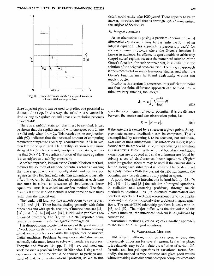
WEXLER: COMPUTATION OF ELECTROMAGNETIC FIELDS
IL & L
i-l,j i,j i+l,j i
(
=h
o +(X,O) I x
Fig. 8. Finite dfierence mesh for exdicit solutionof an initial value problem.
three adjacent pivots can be used to predict one potential at
the next time step. In this way, the solution is advanced in
time as long as required or until error accumulation becomes
unacceptable.
There is a stability criterion that must be satisfied. It can
be shown that the explicit method with one space coordinate
is valid only when O< r< ~. This restriction, in conjunction
with (92), indicates that the increased amount of computing
required for improved accuracy is considerable. If h is halved
then k must be quartered. The stability criterion is still more
stringent for problems having two space dimensions, requir-
ing that O< r< ~. The explicit solution of the wave equation
is also subject to a stability constraint.
Another approach, known as the Crank-Nicolson method,
requires the solution of all node potentials before advancing
the time step. It is unconditionally stable and so does not
require terribly fine time intervals. This advantage is partially
offset, however, by the fact that all potentials at each time
step must be solved as a system of simultaneous, linear
equations. Thus it is called an implicit method. The final
result is that the implicit method is some three or four times
faster than the explicit one.
The reader will find very fine introductions to this subject
in [12] and [44]. Three books, dealing generally with finite
differences and with special sections of interest here, are [3 I],
[34], and [35]. In [30] and [41], initial value problems are
discussed. Recently, Yee [46, pp. 302–307] reported some
results on transient electromagnetic propagation.
It is disappointing to note that in spite of the great amount
of work done on the subject, in practice the solution of many
initial value problems exhausts the capabilities of modern
digital machines. Problems having two spatial dimensions
can easily take many hours to solve with moderate accuracy.
Forsythe and Wasow [34, pp. 11–14] have estimated one
week for such a problem having 10000 nodes. Using a mod-
ern computer, the time would be reduced to perhaps one-
third of that. A three-dimensional problem, solved in fine
429
detail, could easily take 1000 years! There appears to be an
answer, however, and that is through hybrid computation,
the subject of Section VI.
D. Integral Equations
As an alternative to posing a problem in terms of partial
differential equations, it may be cast into the form of an
integral equation. This approach is particularly useful for
certain antenna problems where the Green’s function is
known in advance. Its efficacy is questionable in arbitrarily
shaped closed regions because the numerical solution of the
Green’s function, for each source point, is as difficult as the
solution of the original problem itself. The integral approach
is therefore useful in many free-space studies, and when the
Green’s function may be found analytically without too
much trouble.
Insofar as this section is concerned, it is sufficient to point
out that the finite difference approach can be used. For a
thin, arbitrary antenna, the integral
gives the z component of vector potential. R is the distance
between the source and the observation point, i.e.,
R= [r’–rl. (94)
If the antenna is excited by a source at a given point, the ap-
proximate current distribution can be computed. This is
accomplished by assuming I, to be constant, but unknown,
over each of the n subintervals. The integration in (93) is per-
formed with the trapezoidal rule, thus producing an equation
in n unknowns. Enforcing the required boundary conditions,
n equations are produced and so the unknowns are found by
solving a set of simultaneous, linear equations. (Higher
order integration schemes may be used if the current distri-
bution along each subinterval is presumed to be described
by a polynomial.) With the current distribution known, the
potential may be calculated at any point in space.
A good, descriptive introduction is furnished by [53]. In
[47], [49] -[51], and [54] the solution of integral equations,
in radiation and scattering problems, through matrix
methods is described. Fox [35] discusses mathematical and
practical aspects of Fredholm (corresponding to the elliptic
problem) and Volterra (initial-value problem) integral equa-
tions. The quasi-TEM microstrip problem is dealt with in
[48] and [52]. The major difficulty is the derivation of the
Green’s function; the numerical problem is insignificant by
comparison.
Variational methods (Section V) offer another approach
to the solution of integral equations.
V. VARIATIONAL METHODS
This subject, although not terribly new, is becoming
increasingly important for several reasons. In the first place,
it is relatively easy to formulate the solution of certain dif-
ferential and integral equations in variational terms. Sec-
ondly, the method is very accurate and gives good results
without making excessive demands upon computer store and
430 IEEE TRANSACTIONS ON MICROWAVE THEORY AND TECHNIQUES, AUGUST 1969
time. The solution is found by selecting a field which mini-
mizes a certain integral. This integral is often proportional to
the energy contained in the system and so the method em-
bodies a close correspondence with the real world.
The literature on variational methods is so scattered that
there is good reason to collate and review the principles here.
It is hoped that by reviewing these ideas, and relating them
to microwave problems, the engineer will be encouraged to
make immediate and more general use of them. Otherwise,
the initiate could well spend many months accumulating the
required information before being able to apply it.
The following theory is concerned almost exclusively with
the solution of scalar potentials. Obviously then, static fields
are the immediate beneficiaries. In addition, time-varying
fields, that may be derived from a single vector potential,
are also easily catered for. Although there are some indica-
tions of how to proceed, the author has not seen any general
computer methods for fields with all six components of
electric and magnetic field present. Such fields require both
an electric and magnetic vector potential function to gen-
erate them. Perhaps it would be just as well to solve the
electric and magnetic fields directly rather than through two
potential functions.
A. Hilbert Function Spaces
The concept of a Hilbert function space is, in principle,
very simple and most useful as well. It consists of a set of
functions that obey certain rules. Typically, we will con-
sider those functions belonging to this space as being all
those that are possible solutions of any particular field prob-
lem we wish to solve. For example, the field within a three-
dimensional region bounded by a perfectly conducting sur-
face, having some distribution of charge enclosed, is the
solution of the Poisson equation
–V’1$ = ~. (95)e
@is some function of position, i.e., o(P). We know that the
solution must be one of or a combination of functions of the
form u(P) = sin (lm/a)x. sin (nzr/b)y. sin (nm/c)z in a rec-
tangular region. a, b, and c are the dimensions of the rec-
tangular region and 1, m, and n are integers. If the conduct-
ing boundary of the box is held at zero potential any one or
summation of harmonic functions u will vanish at the wallsand will likewise give zero potential there. These compo-
nents of a Fourier series are akin to vector components of a
real space insofar as a summation of particular proportions
of functions yields another function whereas vector summa-
tion of components defines a point in space. Thus, a sum-
mation of harmonic “components” of the above form de-
fines a particular function which, by analogy, we consider
to be a point in an abstract function space. For this reason,such functions are often called coordinate functions. The
number of dimensions may be finite or perhaps infinite. The
Fourier series is an example of a particular function space
consisting of orthogonal coordinate functions. In general,
however, these functions need not be orthogonal.
The requirements we have placed upon functions belong-
ing to the function space is that they be twice differentiable
(at least) and that they satisfy the homogeneous Dirichlet
condition ~(s) = O at the conducting walls. Such functions
are considered to belong to a linear set. By this is meant that
if any two functions u and v belong to the set, then u+ v and
au (where a is a constant) likewise belong to it. In other
words, the functions u+ v and au are also twice differentiable
and satisfy the relevant boundary conditions.
An inner product
s(U,V)= uv”d~ (96)Q
is defined which, in a sense, gives the “component” of one
function in the “direction” of the other. This appears rea-
sonable when we recall that it is precisely in this way that a
Fourier component, v (omitting, for the moment, the com-
plex conjugate*) of an arbitrary function u is found. It is
really here that the analogy between vector and function
spaces becomes obvious. The reason for including the com-
plex conjugate sign will be shown in a moment. The integra-
tion is performed over Q which may be a one, two, or three-
dimensional physical space depending on the problem. In
our example, the limits correspond to the walls. If u and v
are vector functions of position, we alter (96) slightly to
include a dot between them, thus signifying the integral of
the vector product u. v. In this work, however, we will con-
sider them to be scalars although the generalization of the
subsequent derivations should be fairly straightforward.
In addition to linearity, functions that are elements of a
Hilbert space must satisfy the following axioms. For each
pair of functions u and v belonging to the linear set, a num-
ber (u, v) is generated that obeys the following axioms:
(u, v) = (v, U)*; (97)
(aIu, + a,uz, v) = al(ul, v) + a,(u,, v); (98)
(u, u) > o; (99)if
(u, u) = O then u = O. (100)
Note that the definition of inner product (96) satisfies re-
quirements (97~100) for all well-behaved functions. Note
also that in a real Hilbert space (i.e., one spanned by real
functions), (u, v)= (v, u). From axioms (97) and (98) it is
easy to see that
(u, au) = a“{v, u)* = a’(u, v) (101)
where a is a complex number here.
As a result of these definitions it is clear that an inner
product whose factors are sums can be expanded according
to the rules for multiplication of polynomials. The essential
difference is that the numerical coefficient of the second fac-
tor must be replaced by its complex conjugate in carrying it
outside of the brackets.
It is clear now why the complex conjugate must be em-
ployed in axiom (97). Property (99) states that (u, u)2 O.
Therefore, due to the linearity of the function space, new
elements au must also satisfy (au, au) ~ O where a is any
complex number. If property (100) were of the form {u, v)
WEXLI?R : COMPUTATION OF ELECTROMAGNETIC FIELDS
= (v, u) then we would have that (au, au) =a’(u, u) which,
for arbitrary complex a, would be a complex quantity and
not positive or equal to zero, perhaps even negative. Thus
(99) would be violated.
In the following, we will assume implicitly that the norm
of each function, defined by
]/lL/l == <~~ (102)
is finite. The operation beneath the radical is akin to the
inner product of a vector with itself and so I(UI\ is, by anal-
ogy, a measure of the “length” or “magnitude” of the func-
tion. Insofar as a field is concerned, it is its rms value.
B. The Extremum Formulation
Among elliptic differential equations, there are two classes
we are interested in: the deterministic and the eigenvalue
problem. Forsythe and Wasow [58, pp. 163-164] point out
that variational approaches are “computationally significant
for elliptic problems but not for hyperbolic problems,” They
leave its application to parabolic problems open. The prin-
ciple behind the variational method in solving elliptic prob-
lems rests on an approach which is an alternative to direct
integration of the associated partial differential equation.
The latter approach is often attempted by means of a
Green’s function conversion of a boundary value problem to
an integral equation. It frequently becomes overly compli-
cated, if not altogether impossible to handle, because the
Green’s function itself is difficult to derive. On the other
hand, a variational formulation presents an alternative
choice—to find the function that minimizes the value of a
certain integral, The function that produces this minimal
value is the solution of the field problem. On the face of it
the alternative seems as unappealing as the original problem.
However, due to certain procedures available for determin-
ing this minimizing function, the variational formulation has
great computational advantages. In addition, convergence
can be guaranteed under certain very broad conditions and
this is of considerable theoretical and numerical conse-
quence.Illustrative of the generality of the method is the use of a
general operator notation L. In practice, a great variety of
operations may be denoted by this single letter.
1) The deterministic problem: The deterministic problem
is written
Lu = f (103)
where~=~(l’) is a function of position. If
L=–vz (10.!J
and
.f”~ (105)e
is a known charge distribution, we require to find u, the
solution of the problem under appropriate boundary condi-
tions. (The minus sign in (104) makes the operator positive
definite, as will be shown.) Commonly, these boundary con-
ditions take the forms (58)-(60). In the first instance we will
431
concentrate on certain homogeneous boundary conditions,
i.e., (58}(60) with g =p =g = O.
Ifj= O, (103) becomes Laplace’s equation. IfL= –(V2+k2)
then (103) represents one vector component of an inhomo-
geneous Helmholtz equation. u is then one component of the
vector potential and ~ is an impressed current times p.
To begin the solution, we must consider a set of all func-
tions that satisfy the boundary conditions of the problem
and which are sufficiently differentiable. Each such element
u of the space belongs to the field of definition of the operator
L. Symbolically, u= D.. We then seek a solution of (103)
from this function space.
We consider only se~-a~oint operators. The self-adjoint-
ness of L means that (Lu, v) — (u, Lv), in which u, v= DL, is a
function of u and v and their derivatives on .r only. (s is the
boundary of Q and may be at infinity.) To have a se~-
adjoint problem we must have
(Lz.L,V)=(’u,Lv). (106)
It will be seen that (106) is required in the proof of the min-
imal functional theorem and therefore is a requirement on
those problems treated by variational methods in the
fashion described here. Whether or not an operator is self-
adjoint depends strongly upon the associated boundary
conditions.
In addition, the self-adjoint operator will be required to
be positive definite. The mathematical meaning of this is that
(Lu, U) >0 (107)
whenever u is not identically zero and vanishes only whenU=().
The significance of these terms is best
simple example. Let L= – V2. Therefore
s(Lu, U) = – vvzudo.Q
illustrated by a
(108)
For convenience, take u and v to be real functions. Green’s
identity
S::ds=JnVuVodQ+ SnvV2udfi (109)
converts (108) to the form
s sall(h, v} = Vu. Vudn – V—d!s (110)
$? .s drb
in which the last integration is performed over the boundary.
n is the outward normal. The one-dimensional analogue of
(110) is integration by parts. Similarly
Under either the homogeneous Dirichlet or Neumannboundary conditions, the surface integrals in (1 10) and (1 11)
vanish. Under the homogeneous Cauchy boundary condi-
tion, they do not vanish but become equal. At any rate, L istherefore self-adjoint under any one of these boundary con-
diticms or under any number of them holding ove~ various

432 IEEE TRANSACTIONS ON MICROWAVE THEORY AND TECHNIQUES, AUGUST 1969
sections of the boundary. Property (106) is akin to matrix
symmetry.
Positive definiteness of L is readily observed by making
u= v in (110) and substituting any of the previous homo-
geneous boundary conditions. An additional requirement,
for the homogeneous Cauchy condition to satisfy (107), is
that u> O.
It is a consequence of these properties that we can make
the following statement: if the operator L is positive definite
then the equation Lu=f cannot have more than one solu-
tion. The proof is simple. Suppose the equation to have
two solutions U1 and w such that Lul=f and Lu2 =f. Let
w= u1— uZ. Since the operator is a linear one (a further
requirement) we obtain (Lw, w)= O. Since L is positive
definite, we must then have w = O and so u1= uZ, thus proving
that no more than one solution can exist. This is simply a
general form of the usual proofs for uniqueness of solution
of boundary-value problems involving elliptic partial dif-
ferential equations,
For the solution of a partial differential equation, it was
stated earlier that we will attempt to minimize a certain
integral. The rule for forming this integral, and subsequently,
ascribing a value to it, is a particular example of afunctional.
Whereas a function produces a number as a result of giving
values to one or more of independent variables, a functional
produces a number that depends on the entire form of one
or more functions between prescribed limits. It is, in a sense,
some measure of the function. A simple example is the inner
product (u, v).
The functional we are concerned with, for the soIution of
the deterministic problem, is
F = (Lu, u) – 2(u, ~) (112)
in which we assume that u and f are real functions. The more
general form, for complex functions is
F = (Lu, u) – (ujj) – (f, u). (113)
It is seen that the last two terms of (1 13) give twice the real
part of (u, f ), Concentratingon(112), we will now show that
if L is a positive definite operator, and if Lu =f has a solu-
tion, then (112) is minimized by the solution uO.(The proof of
(113) is not much more involved.) Any other function u~l)~
will give a larger value to F. The proof follows.
Take the function U. to be the unique solution, i.e.,
Lu. = f. (114)
Substitute (114) into (112) for f. Thus
F = (Lu, u) – 2(u, Luo). (115)
Add and subtract (LuO, UO)to the right-hand side of (1 15) and
rearrange noting that if L is self-adjoint (Luo, u)= (Lu, Uo) in
a real Hilbert space. Finally, we obtain
F = {L(u – w), ?A— WJ) — (Luo, Z@). (116)
As L is positive definite, the last term on the right is positive
always and the first is ~ O. F assumes its least value if and
only if u= Uo. To summarize, this minimal functional
theorem requires that the operator be positive definite and
self-adjoint under the stated boundary conditions. It is also
required that the trial functions come from the field of defi-
nition of the operator L; i.e., they must be sufficiently dif-
ferentiable and satisfy the boundary conditions. Otherwise,
a function, which is not a solution, might give a lesser value
to F(u) and delude us into thinking that it is a better approx-
imation to the solution.
From (116), note that the minimal value of the functional
is~i. = _ (LuO, ZJo)F (117)
which occurs for the exact solution UO. Taking L= — V2, we
get
Fmin =s
uOV2uOdfi (118)Q
where the integration is over a volume Q. Now, say that
O(S)= O. Therefore, using Green’s theorem,
Fmin = – JI IVu. 2dL? (119)Q
This integral is proportional to the energy stored in the
region. The field arranges itself so as to minimize the con-
tained energy !
The most common approach, used for finding the mini-
mizing function, is the Rayleigh-Ritz method. As it relies
upon locating a stationary point, we wish to ensure that
once such a point is located, it in fact corresponds to the
solution. This is important because a vanishing derivative is
a necessary, although not a sufficient condition for a mini-
mum. In other words, if a function uOG DL causes (112) to
be stationary, is UOthen the solution of (103)? It is easy to
show that this is so. Let
5(,) = F(uo + q) – F(’uo) (120)
where c is an arbitrary real number. Using (112), substitut-
ing the appropriate expressions, and taking L to be self-
adjoint, we obtain
~(e) = 2c(Lu, – f, ~) + e2(Lq, q) (121)
after some algebraic manipulation. Differentiating
dti— = 2(LU0 – f, 7?)+ w% ~)de
(122)
which must vanish at a stationary point. By hypothesis, this
occurs when c= O, therefore
(Luo – j, TI) = O. (123)
If this is to hold, for arbitrary v, then we must have that
LUO =f identically. In other words, the stationary point cor-
responds to the solution.2) The eigenualue problem: Functional (115) cannot
a priori be used for the eigenvalue problem
Lu = iU (lp~)
because the right-hand side of (124) is not a known function
as is f in (103). The relevant functional, for the eigenvalue
problem, is

WEXLER: COMPUTATION OF ELECTROMAGNETIC FIELDS
~ = @u, ‘u)
(u, u)(125)
where UG DL. Equation (80) is one particular instance of it.
It is often called the Rayleigh quotient. If F~in is the lowest
bound, attained for some ul# O, then F~in = x is the lowest
eigenvalue of operator L and U1is the corresponding eigen-
function.
The proof of the preceding statements is quite direct. Let
v be an arbitrary function from the field of definition of
operator L, i.e., VG DL. Let a be an arbitrary real number.
Therefore ul+a~e DL. We want to investigate the conditions
under which F is stationary about u1. Substitute
into (125) giving
F=
U=ul+a?l (126)
(L(u, + aq), u, + a~). (127)
(’w + q, u, + (q)
As UI and 7 are fixed functions, F is a function only of a,
Differentiate (127) with respect to a. Then, by hypothesis,
the derivative vanishzs when a = O. We therefore get
(Lul, ~)(~~1, ~1) – (L~l, ul)(ul, T?) = O. (128)
With F= F~i. and u= ZL substitute (Lu,, u,) from (125) into
(128). Rearranging
Since v is arbitrary,
LU1 – F~i. UI = O (130)
and so FniD is the lowest eigenvalue Xl and U1the correspond-
ing eigenfunction. It is fairly easy to show [62, pp. 220-221]
that if the minimization of (125) is attempted with trial
functions u orthogonal to uI, in the sense
(u, u,) = o, (131)
that F~i. equals the second eigenvalue AZ. Similarly, defining
a Hilbert space orthogonal to U1and u2.,the next eigenvalue
and eigmvector results, and so on.
As the minimum of (125) corresponds to the lowest eigen-
value k, we can rewrite the functional in the following form:
~ < (Lu, U)
– (u, u) “(132)
The numerator of (132) is positive as L is a positive definite
operator. The denominator is positive by (99). Therefore,
rearranging the inequality
(Lu, U) – h{w, U) >0. (133)
We know that (133) is an equality only for the correct eigen-
value and eigenfunction. Consequently, the left-hand side is
otherwise greater than zero. Therefore, as an alternative to
minimizing (125), we can seek the solution of (1 24) by mini-
mizing
F = {Lu, u) – ~(u, u) (134)
433
instead, Successive eigenvalues and eigenvectors are found
by defining orthogonal spaces as before.
The differential equation, whose solution is a minimizing
function, is known as the Euler’s equation. We are interested
in finding functional whose Euler’s equations we wish to
solve, e.g., the Helmholtz equation, Laplace’s equation, etc.
C. Inhomogeneous Boundary Conditions
In solving Lu =f we have considered homogeneous bound-
ary conditions exclusively. Such a restriction causes the
more important problems (e.g., multiconductor lines at
various potentials) to be excluded. This happens because
self-adjointness cannot be proved. Substitute (58), say, into
the surface integrals of (1 10) and (111) to verify this state-
ment. In addition, the space is nonlinear as well.
Let us express inhomogeneous boundary conditions in the
form
B1’tt Is = h, B2u /, = bz, . 0 . (135)
where the B; are linear operators and the b~ are given func-
tions of position on the boundary. Equations (58>(60) are
the most common examples. The number of boundary con-
ditions required depends upon whether or not u is a vector
and upon the order of the differential equation.
Assume that a function of position w exists which is suffi-
ciently differentiable and satisfies boundary conditions (135).
u’ is not necessarily the solution. As w satisfies the boundary
conditions,
B1w/.=bl,Bzwl.=bz,.... (136)
PuttingV=u —’w ) (137)
B,v 1, = O, B2u /, = O (138)
as the B~ are linear operators. We have now achieved homo-
geneous boundary conditions.
Instead of attempting a solution of
Lu=f (139)
we examine
Lv = L(u – W)
= j – Lw.(140)
Let
f,= f–Lw (141)
and so we can now attempt a solution of
Lv = fl (142)
under homogeneous boundary conditions (13 8). In any par-
ticular case, it still remains to prove self-adjointness for
operator L with functions satisfying (138). If this can beaccomplished, then we may seek the function that minimizes
F = (h, v)– ~(v,fl). (143)
Substitute (137) and (141) into (143). After expansion,
F = (Lzt, U) – 2(tLjf) + (u, Lw) – (h, w)(144)
+ ~(w, f) – @w, w}.

434 IEEE TRANSACTIONS ON MICROWAVE THEORY AND TECHNIQUES, AUGUST 1969
f is fixed and w is a particular function selected (which we
need not actually know). Therefore, the last two terms are
constant and can play no part in minimizing the functional
as we have assumed that u is selected from the set of func-
tions that satisfies the required boundary condition. Other-
wise w would depend on u. The last two terms may be deleted
from (144) because of this.
It now remains to examine (u, Lw) – (Lu, w) in the hope
that u and w maybe separated. If this attempt is successful,
then an amended version of (144) may be written which
excludes the unknown w.
Let us illustrate these principles with a practical example.
Solve
–V%=f (145)
under the boundary condition
‘u(s) = g(s). (146)
The symmetrical form of Green’s theorem is
s J((Wv’u –Uv’w)dfl = )W ‘; – ZL: ds (147)n 8
where n is the external normal to s. Therefore, the third and
fourth terms of (144) are
(u, Lw) – (Lu, W) = h WV2U – wv2w)df2Jfl
-s((148)
du dw—
)W~n —U— ds.
s 8nSince
u(s) = w(s) = g(s) (149)we have
(zL, Lw) - (LzL, w) = ~ (,; - g ;;)ds. (150)s
Only the first term on the right-hand side of (1 50) is a func-
tion of u. In addition to neglecting the last two terms of
(144), the last term of (150) maybe disregarded as well. We
are then left with a new functional to be minimized
F=– sQ“Vzu’”-’ly”+f%” ‘15])Simplify (151) using identity (109)
J– 2 fudfi’.a
Because of (146), the second and third integrals cancel and
we are left with
that the existence of a function w was an unnecessary
assumption.
Although we shall not demonstrate it here, functional
may be derived for the inhomogeneous Neumann and
Cauchy problems. It is also not too difficult to formulate the
solution of electrostatic problems involving media that are
functions of position.
D. Natural Boundary Conditions
Thus far, we have required that trial functions substituted
into (112) should each satisfy the stipulated boundary con-
ditions. Except for the simplest of boundary shapes, such a
constraint makes it practically impossible to select an ap-
propriate set of trial functions. It turns out, however, that
8u/~nl. =p(s) and du/&z] ~+u(s)u(s) = q(s) are natural bound-
ary conditions for the operator L= — V2. The meaning of this
is that we are now permitted to test any sufficiently differenti-
able functions with the certainty that the minimal value
attained by (112) will be due to the solution and none other.
On the other hand, we cannot entertain this confidence under
the Dirichlet boundary condition.
It is easy to show this for the homogeneous Neumann
problem. The form of the functional is
F=sQ(]Vu12-2.fu)dQ. (154)
Substitute u= UO+CZVwhere n need not be in the field of
definition of L. Differentiate with respect to a, make a= O,
and set the result to zero. Finally, employing Green’s
formula,
Nowhere has q been required to satisfy boundary condi-
tions. As v is arbitrary (155) can hold only if – V2U0 =f and
tkJdn = O. Thus the solution is found with appropriate
boundary conditions.
E. Solution by the Rayleigh-Ritz Method
A number of functional have been derived, the minimiza-
tion of which produce solutions of differential or integral
equations. The remaining question is how to locate the mini-
mizing function. The most popular approach is the Ray-
leigh-Ritz method.Assume a finite sequence of n functions
where the aj are arbitrary numerical coefficients. Substitute
(156) into (112). Therefore
which is to be minimized for the solution of (145) under
inhomogeneous boundary conditions (146). It happens, in
this case, that (153) has the same form that homogeneous
boundary conditions would produce. It also turns out, here,
j,k=l j= 1
We now wish to select coefficients aj so that (157) is a min-
imum, i.e.,

WEXLER : COMPUTATION OF ELECTROMAGNETIC FIELDS
dF-==0; ~=l,z...~.
aai) (158)
Rearranging (157) into powers of a;,
+ terms not containing a~.
Now, write k instead of j in the second summation, and
assuming that L is self-adjoint
F = (L+i, @~)U;2+ 2 ~ (U@~,dk)a~akk#i (160)
– 2(f, @~)U;+ . . , .
Differentiating (160) with respect to Ui and setting equal to
zero
S (L&, ~, > ak = (j, ~,) (161)k=l
where i= 1, 2, . . . , n. Writing (161) in matrix form
which may be solved for the coefficients al, az, . . . , an by
the methods of Section II-A.
By a very similar approach [62, pp. 226-229], [63, pp.
193–194], the Rayleigh-Ritz method applied to the eigen-
value problem gives
1?’1
1]..= 0
an
which is a matrix eigenvalue problem of form (21). If the
trial functions are orthonormal, the eigenvalue k occurs only
along the diagonal giving
Similarly, (162) would have diagonal terms only, giving the
solution by the Fourier analysis method.
Because the functions are all real and the operator is self-
adjoint, from (97) and (106) we see that both the A and B
matrices are symmetric. Also, B is positive definite which
permits it to be decomposed, as in (23), using real arithmetic
only, thus resulting in an eigenvalue problem of form (22).
It can be shown that (162) and (163) ammoach the solution
435
of Lu =f and Lu = Au as n approaches infinity, In practice,
the matrices need not be very large for a high degree of
accuracy to result. Notice also that these matrices are dense.
These characteristics determine that direct methods should
be employed in their solution.
F. Some Applications
The bibliography lists several useful references for the
principles of variational methods. See, for example, [58],
[61], and [63]. One of the most detailed treatments avail-
able is [62].
Bulley [57] solves the TE modes in an arbitrarily shaped
guide by a Rayleigh-Ritz approach. The series of trial func-
tions, representing the axial magnetic field, are each of the
form x~y” thus constituting a two-dimensional polynomial
over the waveguide cross section. Obviously, these trial func-
tions cannot be chosen to satisfy all boundary conditions.
However, it turns out that the homogeneous Neumann con-
dition (which H. must satisfy) is natural and so no such con-
straint need be placed on the trial functions. On the other
hand, the homogeneous Dirichlet condition (which is im-
posed upon E,) is not satisfied naturally and so Bulley’s
method is inapplicable in this case. If the guide boundary is
fairly complicated, a single polynomial has difficulty in ap-
proximating the potential function everywhere. In such a
case, Bulley subdivides the waveguide into two or more fairly
regular regions and solves for the polynomial coefficients in
each. In doing this, his approach is virtually that of the
finite-element method. It differs from the usual finite-element
method in the way that he defines polynomials that straddle
subdivision boundaries while others vanish there.
Thomas [67] solves the TE problem by the use of Lagrange
multipliers. In this way, he permits all trial functions while
constraining the final result to approximate the homoge-
neous Dirichlet boundary condition. Although not essential
to his method, he employs a polar coordinate system with
polynomials in r and trigonometric 0 dependence.
Another possible approach, when boundary conditions
are not natural, is to alter the functional in order to allow
trial functions to be unrestricted [64, pp. 1131-1 133].
By a transformation, Yamashita and Mittra [68] reduce
the microstrip problem to one dimension. They then solve
the fields and line capacitance, of the quasi-TEM mode.
The finite element method is an approach whereby a region
is divided into subintervals and appropriate trial functions
are defined over each one of them. The most convenient
shape is the triangle, for two-dimensional problems, and the
tetrahedron in three dimensions. These shapes appear to
offer the greatest convenience in fitting them toegether, in
approximating complicated boundary shapes, and in satisfy-
ing boundary conditions whether or not they are natural.
Silvester [65], [66] has demonstrated the method in wave-
guide problems. An arbitrary waveguide is divided into
triangular subintervals [65]. If the potential is considered to
be a surface over the region, it is then approximated by an
array of planar triangles much like the facets on a diamond.
Higher approximations are obtained by expressing the
potential within each triangle by a polynomial [66].
Because of high accuracy, the finite element approach

436 IEEE TRANSACTIONS ON MICROWAVE THEORY AND TECHNIQUES, AUGUST 1969
appears useful for three-dimensional problems without
requiring excessive computing [69].
The method was originally expounded for civil engineer-
ing applications [70], [71 ], but has recently seen increasing
application in microwaves (e.g., [55], [56] as well as the
previous references).
Other implementations of variational methods are de-
scribed in [59] and [60].
VI. HYBRID COMPUTATION
In Section IV-C two methods for the solution of initial
value (transient) problems were introduced. Through the
explicit approach, one is able to predict the potential of any
node at the next time increment as a function of a few adja-
cent node potentials. The disadvantage is that a stability
constraint demands very small time steps, On the other
hand, the implicit method does not suffer from instability,
and permits larger time steps, but requires simultaneous solu-
tion of all node potentials for each step. As a result, both
techniques are very time consuming and sometimes impos-
sibly slow.
The hybrid computer offers a significantly different ap-
proach to the problem. It consists of two major parts—an
analog and a digital computer. The analog is a model that
obeys the same mathematical laws as the problem being
considered. So the analog, which is presumably easier to
handle, simulates the response of the system being studied.
More precisely, the particular form of analog intended here
is known as an electronic dl~erential analyzer. By connecting
electronic units (which perform integration, multiplication,
etc.) together, it is possible to solve ordinary differential
equations under appropriate initial conditions [74]. The
solution is given as a continuous waveform. Whereas the
digital computer will solve the problem in a number of dis-
crete time-consuming steps, the analog gets the answer
almost immediately. The analog computer is faster; it is a
natural ordinary differential equation solver.
This is fairly obvious for an ordinary differential equation,
but how is a partial differential equation to be solved? Con-
sider a one-dimensional diffusion equation
Wp 11$(165)
==%”
(Many of the following comments apply to the wave equa-
tion as well.) Discretize the spatial coordinates at the ith
node. We have, using central differences,
At boundaries, forward or backward differences must be
used.We have therefore reduced the partial differential equa-
tion to a system of ordinary differential equations, one at
each node point. This is known as the DSCT (discrete-space-
continuous-time) analog technique. Other formulations
exist as well. The time response of the potential at i, i.e.,
cA(t), may be found by integrating (166). Other functions of
-’+Jt)EG=lRl .AI+i.,(t)0 n
+I+l(t) 0 n
I *
T* ~t
Fig. 9. Single node, DSCX analog of the one-dimensional diffusion equation.
—— — —
,+O(t) l+,(t) )+2(t) ~+3(t) ~$dt) FJt)● xo .2 .4 .6 .8 1.0
Fig, 10. Simultaneous solution of the one-dimensional difTusion equa-tion, by DSC’T analog, with four internal nodes.
time @i--l(t) and &-l(t) are forcing functions which are asyet unknown. Assume, for the moment, that we know them
and let us see how the analog computer can produce the time
response Oi(t).
Fig. 9 indicates, symbolically, the operation of an analog
computer in solving (166). Circles indicate multipliers, the
larger triangle represents an integrator, and the smaller one
an inverter. Assume that functions r&.l(t)and ~ti l(t) are
known, recorded perhaps, and played back into the inte-
grator with the initial.value 4,(0). They are all multiplied by
l/h2 and fed into the integrator in the ratios indicated. This
is then integrated giving
h, ,’ (+i-l(t) – 2@i(0 + b+l(t))dt.@,(t) = : s (167)
In fact, the integrator produces the negative of (167), i.e.,
–@;(t). This is fed back thus completing the circuit and
allowing the process to continue to any time t. An inverter
follows the integrator to alter the sign if required.
We do not, of course, know the forcing functions +;-l(t)
and &l(t).They are the responses of adjacent nodes, and
they in turn depend upon forcing functions defined at other
nodes. However, the boundary conditions @o(t)and @s(t)
are known in advance as well as the initial conditions 4,(0)for all nodes, or +(x, t) where t= O.
To solve the entire finite difference system at one time
requires as many integrators as there are internal nodes
available. This is demonstrated in Fig. 10. (The factor l/h2 is
incorporated into the integrators for simplicity.) What this
scheme does, in fact, is to solve a system of four coupled
ordinary differential equations in parallel. The analog hastwo obvious advantages: 1) rapid integration; and 2)
parallel processing.
In order to reduce discretization error, one increases the
number of nodes. If the intention is to solve all node poten-
tials simultaneously, due to the limited number of integrators
available, the number of nodes must be small. One alterna-

WEXLER : COMPUTATION OF ELECTROMAGNETIC FIELDS 437
tive strategy is to attempt an iterative technique reminiscent
of the digital relaxation procedure. This is done by making
an initial guess at the transient response of each internal
node, frequently choosing just constant time responses as
shown by the uppermost curve in Fig, 11. Having made this
initial guess at each node’s time response, each @i(t) is solved
sequentially as described previously. Each di(t), upon being
solved, is transmitted via an ADC (analog-digital converter)
to the digital computer where it is stored as discrete data in
time. Attention is then focused upon node i+ 1 with adjacent
potential responses transmitted from store through DAC
(digital-analog conversion) equipment. OwI(t) is then com-
puted by the analog with the smoothed d,(t) and @A,(t)
acting as forcing functions. The flow of data is indicated by
arrowheads in Fig. 11. In sequence then, node transient
responses are updated by continually scanning all nodes
until convergence is deemed to be adequate. In effect, this
procedure involves the solution of coupled ordinary differ-
ential equations, one for each node, by iteration.
An additional refinement is to solve, not one node poten-
tial at a time but groups of them. The number that can be
catered for is, as pointed out before, limited by the amount of
analog equipment available. This parallel processing speeds
the solution of the entire problem and is one of the ad-
vantages over the purely digital scheme. Furthermore, be-
cause of the continuous time response (i.e., infinitesimal
time steps), we have an explicit method without the disad-
vantage of instability.
Parallel solution of blocks of nodes is the logical approach
for two dimensional initial value problems. Fig. 12(a) shows
one possible format involving the solution at nine nodes.
Forcing functions correspond to solutions at the twelve
nodes excluded from the enclosed region. The set of nodes
being considered would scan the region with alterations to
the block format near boundaries. The making of such log-
ical decisions, as well as storage, is the job of the digital com-
puter.
Hsu and Howe [75] have presented a most interesting
feasibility study on the solution of the wave and diffusion
equations by hybrid computation. The procedures mentioned
above are more fully explained in their paper. Hsu and
Howe did not actually have a hybrid computer available at
the time of their experiments; their results were obtained
through a digital simulation study. Hybrid computation of
partial differential equations is still in its early stages and
little has been reported on actual computing times. How-
ever, some preliminary reports indicate speeds an order of
magnitude greater than digital computing for such problems.
An intriguing possibility, for hybrid solution of the elliptic
problem, is the method of lines. The mathematical theory is
presented in [62, pp. 549–566]. The principle behind it isthat discretization is performed along one coordinate only,
in a two-dimensional problem, giving us a sequence of
strips (Fig. 12(b)). In three dimensions, two coordinates are
discretized, producing prisms. We thus obtain a number of
coupled difference-differential equations. Each equation is
then integrated under boundary conditions at each end of its
strip and with forcing functions supplied by adjacent strips.
km?,, ,,, ,,, -,
+2(7 , =rd I \
o— t
Fig. 11. Iterative DSCT solution of the diffusion equation.
Fig. 12. (a) Iterative, parallel processing scheme for the initial valueproblem. (b) Method of lines for the elliptic problem.
The analog computer does not as easily solve two-point
boundary value problems as it does initial value problems.
A common technique is to attempt various initial values at
one end of the strip until the far-end boundary condition is
satisfied. This can often be very wasteful. A better idea is to
solve each two-point boundary value problem as two initial
value problems [7, pp. 239–240], [74, pp. 83–85]. This could
be done for each strip in turn or perhaps in groups. The
entire region must then be scanned repeatedly, in this
fashion, until convergence occurs.
For other approaches to the solution of partial differential
equations by hybrid computation, see [72], [73], [74], [76],
and [77]. Finally, the hybrid system makes the Monte Carlo
method [74, pp. 239–242, 360] a more attractive one.
It should be emphasized that hybrid solution of partial
differential equations is still in its infancy. This section, in
part an optimistic forecast, is intended to show that digital
computing has no monopoly and certainly should not be
considered a more “respectable” branch of computing. The
analog machine integrates rapidly, and the digital machine
has the ability to store information and make logical de-
cisions. It therefore stands to reason that working as a pair,
each in its own domain, substantial advantages will be
gained.
VII. CONCLUDING REMARKS
The intention of this paper is to familiarize the readerwith the principles behind the numerical analysis of elec-
tromagnetic fields and to stress the importance of a clear
understanding of the underlying mathematics. Improper
numerical technique causes one to run up against machine
limitations prematurely.
In the immediate future, emphasis should perhaps be
placed upon the development of finite difference and varia-
tional techniques for solving fields having all components of
electric and magnetic field present everywhere. To date,
with a few exceptions (e.g., [59, pp. 172–1 88]), most methods

438 IEEE TRANSACTIONS ON MICROWAVE THEORY AND TECHNIQUES, AUGUST 1969
appear to permit solution only of fields deriveable from a
single scalar potential. It is not difficult to formulate and
solve field problems in a multidielectric region, but it may
not correspond to the actual electromagnetic problem. This
is indicated by the continuing discussion of “quasi-TEM”
microstrip waves.
Variational methods are being implemented now to a
greater extent than ever before. Hybrid computation is
likely to assume a significant, or perhaps commanding, role
in field computation due to its greater speed and flexibility.
Ahnost certainly, general purpose scientific computers will
permit optional analog equipment to be added, the analog
elements to be connected and controlled from the program.
Beyond this, it is virtually impossible to predict. It is futile
wishing for computer technology to keep pace with our
problem solving requirements. We have outstripped all
machine capabilities already. The greatest hope is in the
development of new numerical techniques. Due to his in-
sight into the physical processes and his modeling ability,
the engineer is ideally suited to this task.
ACKNOWLEDGMENT
The author wishes to express his appreciation to P. A.
Macdonald and G. Oczkowski for discussions on numerical
and programming techniques and to Dr. J. W. Bandler for
conversations on microwave problems. Views expressed
by M. J. Beaubien and B. H. McDonald, on finite differences
and hybrid computing respectively, were invaluable. Dr.
W. G. Mathers, of Atomic Energy of Canada Ltd., made a
number of helpful suggestions. Also to be thanked are librar-
ians, R. Thompson, Mrs. F. Ferguson, and Mrs. D. Glober-
man, for locating and checking many references, and Miss
L. Milkowski for carefully typing the manuscript.
Thanks are due W. J. Getsinger, Guest Editor of this
Special Issue, for the invitation to write this review paper.
REFERENCES
General Numerical Analysis
[1] I. S. Berezin and N. P. Zhidkov, Computing Methods, vols. I andII. Oxford: Pergamon, 1965.
[2] D. K. Faddeev and V. N. Faddeeva, Computational Methods ofLinear Algebra. San Francisco: Freeman, 1963.
[3] C.-E. Froberg, Introduction to Numerical Analysis. Reading,Mass.: Addison-Wesley, 1965.
[4] E. T. Goodwin, Modern Computing Methods. London: H. M.Stationery Office, 1961.
[5] R. W. Hamming, Numerical Methods for Scientists attd Engineers.New York: McGraw-Hill, 1962.
[6] P. Henrici, Elements of Numerical Analysis. New York: Wiley,
[7]
[8]
[9]
[10]
[11]
[12]
[13]
1964.F. B. Hildebrand, Introduction to Numerical Analysis. New York:McGraw-Hill, 1956.E. Isaacson and H. B. Keller, Analysis of Numerical Methods.New York: Wiley, 1966.M. L. James, G. M. Smith, and J. C. Wolford, Applied NumericalMethods for Digital Computation with Fortran. Scranton, Pa.:International Textbook, 1967.L. G. Kelly, Handbook of Numerica[ Methods and Applications.Reading, Mass.: Addison-Wesley, 1967.C. Lanczos, Applied Analysis. Englewood Cliffs, N. J.: Prentice-Hall, 1956.M. G. Salvadori and M. L. Baron, Numerical Methods in Engineer-ing. Englewood Cliffs, N. J.: Prentice-Hall, 1964.J. H. Wilkinson, Rounding Errors in Algebraic Processes. Lon-don: H. M. Stationery Office, 1963.
Matrices and Linear E@ations
[14] B.A. Carr&, “The determination of the optimum accelerating fac-tor for successive over-relaxation,” Computer J., vol. 4, pp. 73-7S,1961.
[15] G. E. Forsythe and C. B. Moler, Computer Solution of LinearAlgebraic Systems. Englewood CM%, N. J.: Prentice-Hall, 1967.
[16] J. N. Franklin, Matrix Theory. Englewood Cliffs, N. J.: Pren-tice-Hall, 1968.
[17] L. A. Hageman and R. B. Kellogg, “Estimating optimum over-relaxation parameters,” Math. Computation, vol. 22, DV. 60-68,January 19&S.
. . .
[18 ] T. Lloyd and M. McCallion, “Bounds for the optimum over-relaxation factor for the S.O.R. solution of Laplace type equa-tions over irregular regions;’ Computer J., vol. 11, pp. 329-331,November 1968.
[19] T. J. Randall, “A note on the estimation of the optimum succes-sive overrelaxation parameter for Laplace’s equation,” ComputerJ., vol. 10, pp. 400-401, February 196S.
[20] J. K. Reid, “A method for finding the optimum successive over-relaxation parameter;’ Computer J., vol. 9, pp. 201-204, August1966.
[21 ] J: F. Traub, Iterative Methods for the Solution of Equations.
Englewood Cliffs, N. J.: Prentice-Hall, 1964.[22] R. S. Varga, Matrix Iteratioe Analysis. Englewood ClilTs, N. J.:
Prentice-Hall, 1962.[23 ] D. C. Walden, “The Givens-Householder method for finding
eigenvalues and eigenvectors of real symmetric matrices,” M.I.T.Lincoln Lab., Cambridge, Mass., Tech. Note 1967-51, October 26,1967.
[24] J. R. Westlake, A Handbook of Numerical Matrix Inversion andSolution of Linear Equations. New York: Wiley, 1968.
[25] J. H. Wilkinson, The Algebraic Eigenvalue Problem. New York:Oxford, 1965.
[26] J. H. Wilkinson, “Householder’s method for the solution of thealgebraic eigenproblemfl Computer J., pp. 23-27, April 1960.
Finite Dl~erence Solution of Partial Dl~erential Equations
[27] M. J. Beaubien and A. Wexler, “An accurate finite-differencemethod for higher order waveguide modes,” IEEE Trans. Micro-waue Theory and Techniques, vol. MTT-16, pp. 1007-1017, Decem-ber 1968.
[28] C. T. Carson, “The numerical solution of TEM mode trans-mission lines with curved boundaries,” IEEE Trans. Microwave
Theory and Techniques (Correspondence), vol. MTT-15, pp. 269-270, April 1967.
[29] I. A. Cermak and P. Silvester, “Solution of 2-dimensional field
[30]
[31]
[32]
[33]
[34]
[35]
[36]
[37]
problems by boundary relaxation,” Proc. ZEE (Londpn), vol. 115,pp. 1341-1348, September 1968.F. Ceschino, J. Kuntzmann, and D. Boyanovich, Numerical Sola-tion of Initial Value Problems. Englewood Cliffs, N. J.: Prentice-Hall, 1966.L. Collatz, The Numerical Treatment of Differential Equations.Berlin: Springer, 1960.J. B. Davies and C. A. Muilwyk, “Numerical solution of uniformhollow waveguides with boundaries of arbitrary shape;’ Proc.IEE (London), vol. 113, pp. 277-284, February 1966.J. W. Duncan, “The accuracy of finite-difference solutions ofLaplace’s equation;’ IEEE Trans. Microwave Theory and Tech-niques, vol. MTT-15, pp. 575–582, October 1967.G. F. Forsythe and W. R. Wasow, Finite-Difference Methods for
Partial Differential Equations. New York: Wiley, 1960.L. Fox, Numerical Solution of Ordinary and Partial Differential
Equations. Oxford: Pergamon, 1962.H. E. Green, “The numerical solution of some important trans-mission-line problems,” IEEE Trans. Microwave Theory andTechniques, vol. MTT-13, pp. 676692, September 1965.D. Greensvan, Introductory Numerical Analvsis of El~irXic Bound-
ary Value Problems. Ne; York: Harper a;d R;w, i965.[38 1 C. B. Moler. “Finite difference methods for the eizenvalues of--
Laplace’s operator,” Stanford University Comp&er ScienceDept., Stanford, Calif., Rept. CS32, 1965.
[39] H. Motz, “The treatment of singularities of partial differentialequations by relaxation methods;’ @art. Appl. Math., vol. 4, pp.371–377, 1946.
[40] C. A. Muilwyk and J. B. Davies, “The numerical solution of rec-tangular waveguide junctions and discontinuities of arbitrary
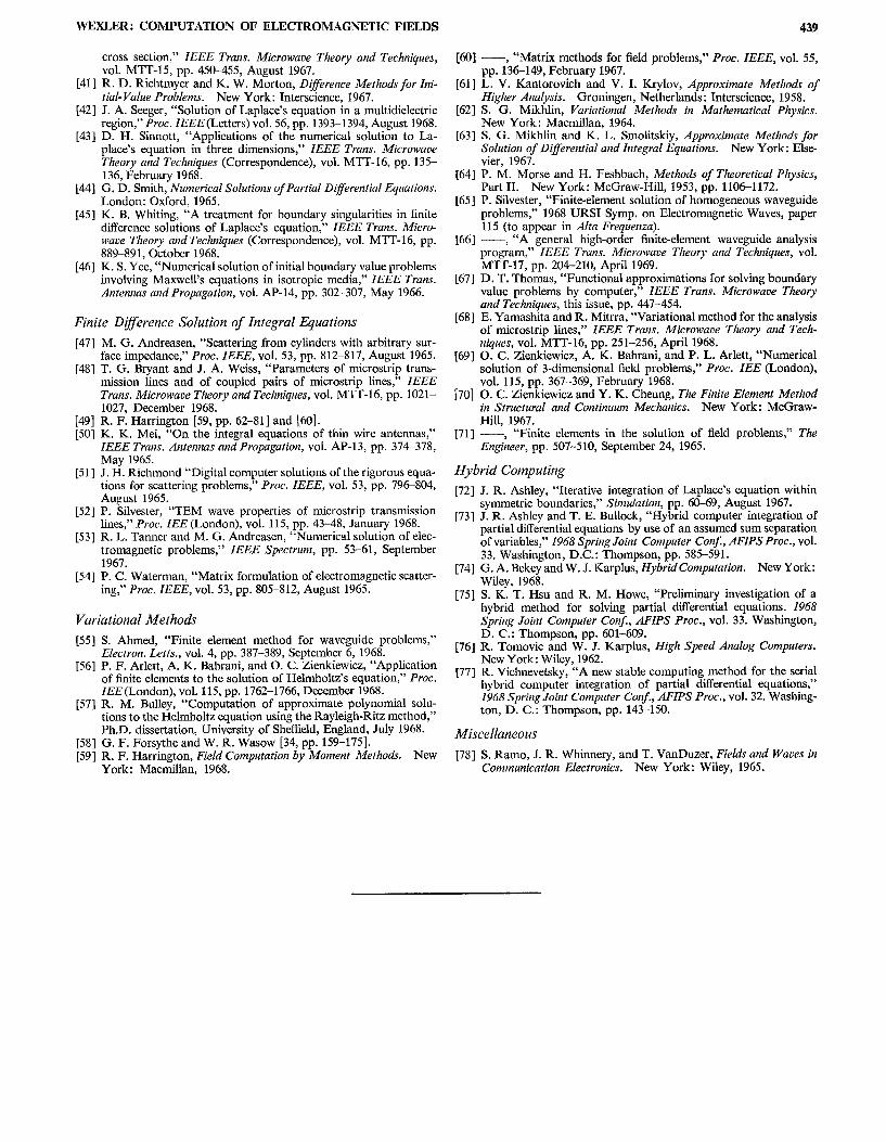
WEXLER : COMPUTATION OF ELECTROMAGNETIC FIELDS ..-
cross section,” IEEE Trans. Microwave Theory and Techniques,
VO1. MTT-15, pp. 450-455, August 1967.[41 ] R. D. Richtmyer and K. W. Morton, Difference Methods for Ini-
tial- Value Problems. New York: Interscience, 1967.[42] J. A. Seeger, “Solution of Laplace’s equation in a multidielectric
region,” Proc. ZEEE (Letters) vol. 56, pp. 1393–1 394, August 1968.[43 ] D. H. Sinnott, “Applications of the numerical solution to La-
place’s equation in three dimensions,” IEEE Trans. Microwave
Theory and Techniques (Correspondence), vol. MTT-16, pp. 135-136, February 1968.
[44] G. D. Smith, Numerical Solutions of Partial Differential Eqaations.
London: Oxford, 1965.[45 ] K. B. Whiting, “A treatment for boundary singularities in finite
ditTerence solutions of Laplace’s equation;’ IEEE Trans. Micro-waue Theory and Techniques (Correspondence), vol. MTT-1 6, pp.889-891, October 1968.
[46] K. S. Yee, “Numerical solution of initial boundary value problemsinvolving Maxwell’s equations in isotropic media,” IEEE Trans.Antennas and Propagation, vol. AP-14, pp. 302-307, May 1966.
Finite Dl~erence Solution of Integral Equations
[47] M. G. Andreasen, “Scattering from cylinders with arbitrary sur-face impedance:’ Proc. IEEE, vol. 53, pp. 812-817, August 1965.
[48] T. G. Bryant and J. A. Weiss, “Parameters of microstrip trans-mission lines and of coupled pairs of microstrip lines,” IEEE
Trans. Microwave Theory and Techniques, vol. MTT-16, pp. 1021-1027, December 1968.
[49] R. F. Barrington [59, pp. 62-81] and [60].[50] K. K. Mei, “On the integral equations of thin wire antennas,”
IEEE Trans. Antennas and Propagation, vol. AP-I 3, pp. 376378,May 1965.
[51 ] J. H. Richmond “Digital computer solutions of the rigorous equa-tions for scattering problems;’ Proc. IEEE, vol. 53, pp. 79tk804,August 1965.
[52] P. Silvester, “TEM wave properties of microstrip transmissionlines,” Proc. ZEE (London), vol. 115, pp. 43-48, January 1968.
[53] R. L. Tanner and M. G. Andreasen, “Numerical solution of elec-tromagnetic problems+” IEEE Spectrum, pp. 53–61, September1967.
[54] P. C. Waterman, “Matrix formulation of electromagnetic scatter-ing;’ Proc. IEEE, vol. 53, pp. 805–812, August 1965.
Variational Methods
[55] S. Ahmed, “Finite element method for waveguide problems,”Electron. Letts., vol. 4, pp. 387-389, September 6, 1968.
[56] P. F. Arlett, A. K. Bahrani, and O. C. Zienkiewicz, “Applicationof finite elements to the solution of Helmholtz’s equation,” Proc.ZEE (London), vol. 115, pp. 1762-1766, December 1968.
[57] R. M. Bulley, “Computation of approximate polynomial solu-tions to the Helmholtz equation using the Rayleigh-Ritz method,”Ph.D. dissertation, University of Sheffield, England, July 1968.
[58] G. F. Forsythe and W. R. Wasow [34, pp. 159-175].[59] R. F. Barrington, Field Computation by Moment Methods. New
York: Macmillan, 1968.
439
[60] — “Matrix methods for field problems:’ Proc. IEEE, vol. 55,pp. 1’36-149, February 1967.
[61 ] L. V. Kantorovich and V. I. Krylov, Approximate Methods of
Higher Analysis. Groningen, Netherlands: Interscience, 1958.[62] S. G. Mikhlin, Variational Methods in Mathematical Physics.
New York: Macmillan, 1964.[63] S. G. Mikhlin and K. L. Smolitskiy, Approximate Methods for
Solution of Differential and Integral Equations. New York: Else-vier, 1967.
[64] P. M. Morse and H. Feshbach, Methods of Theoretical Physics,Part II. New York: McGraw-Hill, 1953, pp. 1106-1172.
[65 ] P. Silvester, “Finite-element solution of homogeneous waveguideproblemsj’ 1968 URSI Symp. on Electromagnetic Waves, paper115 (to appear in Alta Frequenza).
[66] — “A general high-order finite-element waveguide analysisproglam,” IEEE Trans. Microwave Theory and Techniques, vol.
MTT-17, pp. 204-210, April 1969.[67] D. T. Thomas, “Functional approximations for solving boundary
value problems by computer:’ IEEE Trans. Microwave Theory
and Techniques, this issue, pp. 447–454.[68] E. Yamashita and R. Mitrra, “Variational method for the analysis
of microstrip lines,” IEEE Trans. Microwave Theory and Tech-
niques, vol. MTT-16, pp. 251–256, April 1968.[69] O. C. Zienkiewicz, A. K. Bahrani, and P. L. Arlett, “Numerical
solution of 3-dimensional field problems:’ Proc. ZEE (London),vol. 115, pp. 367–369, February 1968.
[70] O. C. Zienkiewicz and Y. K. Cheung, The Finite Element Method
in Structural and Continuum Mechanics. New York: McGraw-Hill, 1967.
[71] — “Finite elements in the solution of field problems,” The
Eng~eer, pp. 507-510, September 24, 1965.
Hybrid Computing
[72] J. R. Ashley, “Iterative integration of Laplace’s equation withinsymmetric boundaries;’ Simulation, pp. 60-69, August 1967.
[73] J. R. Ashley and T. E. Bullock, “Hybrid computer integration ofpartial differential equations by use of an assumed sum separationof variables:’ 1968 Spring Joint Computer Conj, AFIPS Proc., vol.33. Washington, D.C.: Thompson, pp. 585-591.
[74] G. A. Bekey and W. J. Karplus, Hybrid Computation. New York:Wiley, 1968.
[75] S. K. T. Hsu and R. M. Howe, “Preliminary investigation of ahybrid method for solving partial differential equations. 1968Spring Joint Computer Con$, AFIPS Proc., vol. 33. Washington,D. C.: Thompson, pp. 601-609.
[76] R. Tomovic and W. J. Karplus, High Speed Analog Computers.New York: Wiley, 1962.
[77] R. Vichnevetsky, “A new stable computing method for the serialhybrid computer integration of partial differential equations;’1968 Spring Joint Compater Corf, AFIPS Proc., vol. 32. Washing-ton, D. C.: Thompson, pp. 143-150.
Miscellaneous
[78] S. Ramo, J. R. Whinnery, and T. VanDuzer, Fields and Waues in
Communication Electronics. New York: Wiley, 1965.