computational fluid dynamics analysis of surgical adjustment of
TRANSCRIPT

1 | P a g e
COMPUTATIONAL FLUID DYNAMICS ANALYSIS OF SURGICAL ADJUSTMENT OF LEFT VENTRICULAR ASSIST DEVICE IMPLANTATION TO MINIMIZE STROKE RISK Andres F. Osorio1 [email protected] Ruben Osorio1 [email protected] Andres Ceballos1 [email protected] Reginald Tran1
[email protected] William Clark1 [email protected] Eduardo A. Divo1,2
[email protected]; [email protected]
I. Ricardo Argueta-Morales3
[email protected] Alain J. Kassab1 [email protected] William M. DeCampli3,4 [email protected] 1 Department of Mechanical, Materials and Aerospace Engineering, College of Engineering and Computer Science, University of Central Florida, Orlando, FL, USA 2 School of Engineering Technology, Daytona State College, Daytona Beach, Florida, USA 3 Congenital Heart Institute at Arnold Palmer Hospital for Children, Orlando, FL, USA 4 Department of Surgery, College of Medicine, University of Central Florida, Orlando, Florida, USA __________________________________________________________________________________

2 | P a g e
Abstract
Background: Currently, mechanical support is the most promising alternative to cardiac transplantation. Ventricular Assist
Devices (VADs) were originally used to provide mechanical circulatory support in patients awaiting planned heart
transplantation (“bridge-to-transplantation” therapy). The success of short-term bridge devices led to clinical trials
evaluating the clinical suitability of long-term support (“destination” therapy) with left ventricular assist devices (LVADs).
The first larger-scale, randomized trial that tested long-term support with a LVAD reported a 44% reduction in the risk of
stroke or death in patients with an LVAD. In spite of the success of LVADs as bridge-to-transplantation and long-term
support, patients managed by these devices are still at risk of several adverse events. The most devastating complication
is caused by embolization of thrombi formed within the LVAD or inside the heart into the brain. Prevention of thrombi
formation is attempted through anticoagulation management and by improving LVADs design; however there is still
significant occurrence of thromboembolic events in patients. Investigators have reported that the incidence of
thromboembolic cerebral events ranges from 14% to 47% over a period of 6-12 months.
Methods and Approach: An alternative method to reduce the incidence of cerebral embolization is proposed by the co-
authors, and the hypothesis is that it is possible to minimize the number of thrombi flowing into the carotid arteries by an
optimal placement of the LVAD outflow conduit, with or without the addition of aortic bypass connecting the ascending
aorta (AO) and the innominate artery (IA), or left carotid artery (LCA). This paper presents the computational fluid
dynamics (CFD) analysis of the aortic arch hemodynamics using a representative geometry of the human aortic arch with
or without an alternative aortic bypass.. In order to study the trajectory of the thrombi within the aortic arch bed, the CFD
code Fluent 6.3 is utilized to resolve the flow field and to solve the Lagrangian particle-tracking of thrombi released
randomly at the inlet of the LVAD cannula.
Results: Results are presented for simulations of thrombi in the range of 2mm-5mm. Percentage of individual diameter as
well as aggregate diameter thrombi flowing to the carotid arteries as a function of LVAD conduit placement and aortic
bypass implantation are reported. The influence of the LVAD conduit implantation and bypass reveal a nearly 50%
variation in predicted cerebral embolism rates.

3 | P a g e
Conclusions: The adjustment of the location of the anastomosis of the LVAD inflow cannula as well as its angle of
incidence plays a significant role in the level of thromboembolisms. By proper adjustment in this CFD study of a synthetic
model of an aortic arch bed, we found nearly a 50% reduction of cerebral embolism could be achieved for a configuration
consisting of a shallow angle of implantation over a baseline normal incidence of the LVAD cannula. Within the limitations
of our model we have established that the LVAD implantation geometry is an important factor and should be taken into
consideration when implanting an LVAD. It is possible that other parameters such as distance of the LVAD outflow cannula
to the root of the IA, could affect the thrombi embolization probabilities. However, the results of this study suggest that the
risk of stoke may be significantly reduced by as much as 50% by tailoring the VAD implantation by a simple surgical
maneuver. The results of this line of research may ultimately lead to techniques that can be used to estimate the optimal
LVAD configuration in a patient specific manner by pre-operative imaging.
Key words: LVAD, CFD, Lagrangian tracking, thromboembolism.

4 | P a g e
INTRODUCTION
Heart failure is a major public health problem affecting over 5 million people in the United States [1]. Orthotopic heart
transplantation is the best treatment option for patients with end-stage heart failure; however, the number of patients
awaiting heart transplantation far exceeds the number of donor hearts available [2]. At the present time, mechanical
circulatory support is the most promising alternative to cardiac transplantation [3]. Ventricular Assist Devices (VADs) were
originally used to provide mechanical circulatory support in patients awaiting planned heart transplantation (“bridge-to-
transplantation” therapy). The success of short-term bridge devices led to clinical trials evaluating the clinical suitability of
long-term support with left ventricular assist devices (LVADs). The first large-scale, randomized trial that tested long-term
support with an LVAD reported a 44% reduction in the risk of stroke or death in patients treated with an LVAD [4]. The
results of this study provided evidence for the Food and Drug Administration (FDA) approval of an LVAD for so-called
“destination” therapy in 2002 [5]. The well-documented imbalance between the number of potential transplant recipients
and available donor organs, and the technological advances in device design and miniaturization have allowed LVADs to
become a well-established therapy for adults and children [6], [7].
There are two types of LVADs: the 1st generation pulsatile-type that were designed to capture the cardiac output and
the 2nd generation of continuous axial-flow type LVADs such as the Heart Assist 5 (MicroMed, Houston, Texas), Jarvik
2000 (Jarvik Heart, Inc., Manhattan, New York) and Heartmate II (Thoratec Corporation, Inc., Pleasanton, California) that
are designed to augment cardiac output and provide continuous flow [8], [9]. The latter type of LVADs significantly reduce
but do not eliminate pulsatility [10], [11] associated with the native circulation. Moreover, the waveforms generated by
LVADs are closer to periodic than the natural waveform of the cardiac cycle and for a sick heart exhibit a low pulsatility
index. Continuous flow LVADs have shown much promise in terms of durability and superior clinical outcome [12], [13].
Figure 1: DeBakey LVAD and associated nomenclature.
Standard LVAD Configuration
(1) Inflow conduit(2) LVAD(3) Outflow Cannula(4) Ascending Aorta
12
1 1
13
1 4

5 | P a g e
Preservation of organ function using continuous flow LVADs has been demonstrated in a long term study [14]. It is this
second and newest generation of continuous flow LVADs that is the subject of the proposed investigation.
Survival with LVADs is currently in the range of 50% at 1 year. Furthermore, follow up studies have reported that
patients, children or adults, requiring pre-transplantation VAD support have long-term survival similar to that of patients
not requiring mechanical circulatory support [15], [16]. However, there are numerous adverse events that may occur
following initiation of circulatory support that can substantially diminish the benefit of this life-saving technology [5].
Bleeding, right-sided heart failure, air embolism, and progressive multisystem organ failure are the most common causes
of early morbidity and mortality after placement of an LVAD. The most common complications in the late postoperative
period are infection, thromboembolism, and failure of the device [3]. The most devastating complications are neurologic,
and are caused by embolization of particulate matter or air into the brain. Particulate matter can come from a thrombus
that enters the LVAD from the atrium or ventricle, or a thrombus that forms within the LVAD [5], [17]. Systemic thrombo-
embolization has been reported to occur considerably less often than cerebral [18].
All LVADs carry a risk for thromboembolism. This risk factor has been addressed, mainly, by improving the device
design and attempting adequate anticoagulation. State of the art technology is used to generate engineering designs of
LVADs that avoid step changes in lumen size, improperly sized conduits, surface imperfections of 10µm or larger, sharp
transitions of flow, small radius, right angle bends, multiple cross-sectional flow areas, multiple joints, and surface
protrusions; with the ultimate goal of minimizing thrombus formation. Adequate anticoagulation remains a key issue with
the use of LVADs; the need to balance the risk of bleeding with that of thrombosis complicates treatment in patients with
LVADs, and the ideal regimen for device-related thrombosis prophylaxis has not been determined. Conventional
anticoagulation management includes unfractionated heparin (UFH) in the post-operative period, oral anticoagulants in
the outpatient setting, and adjunctive anti-platelet therapy (clopidogrel) [19]-[21]. Despite all of these efforts, investigators
have reported that the incidence of thromboembolic cerebral events ranges from 14% to 47% over a period of 6 to 12
months [18], [22].
Thrombogenesis in LVADs is attributed to various mechanisms including platelet activation associated with non-
physiological flow patterns such as stagnation and re-circulating flows [23]-[25]. Consequently, several research groups
[23]-[30] have sought to characterize the hemodynamics of flows induced by LVADs utilizing powerful simulation
capabilities afforded by computational fluid dynamics (CFD). Most studies consider 3D models and steady flow while
some undertook transient modeling through the cardiac cycle [26], [30]. In all cases blood was modeled as a Newtonian

6 | P a g e
fluid and while various approaches were taken utilizing either synthetic representative geometries or by retrieving
geometric data of the aortic arch from CT scans of patients [30], these studies generally focused on abnormal
hemodynamics and shear stress distributions as thrombogenic. None of these studies considered predicting the paths
taken by the thrombi as they are carried by the flow in the aortic arch and if there was a possibility to preferentially guide
the thrombi, should they occur, away from the left and right carotid arteries and vertebral arteries by controlling the LVAD
conduit outflow insertion angle and location, or by some other means such as utilizing an aortic-to-innominate or aortic-to-
left-carotid bypass graft. This is the approach investigated in this paper. Thus, we depart from the premise that, despite all
attempts for mitigation, thrombus formation is an event that is currently afflicting a significant population of VAD patients,
and we offer a possible engineering-inspired surgical solution to what is a fluid mechanics problem, that is tailoring of the
VAD implantation to preferentially direct thrombi away from vertebral and carotid arteries to the descending aorta where
their impact on the patient is lessened compared to the devastating effect of the neurological ravages of stroke or the
ultimate death of the patient. That is, in this paper we seek to test the hypothesis that there is an optimal LVAD
implantation geometry that reduces the incidence of thromboembolism to the vertebral and carotid arteries in LVAD
patients, and we employ well-established computational fluid dynamics tools to examine this hypothesis. We first present
the geometry of the aortic vasculature under consideration, we then describe the computational model we utilized to
determine the flow fields and thrombus paths along with flow rate and boundary conditions we imposed, and we present
results and conclusions.
AORTIC ARCH MODEL
The aortic arch connects the ascending aorta (AO) with the descending aorta (DA). The most common aortic arch
branching pattern in humans consists of three great vessels originating from the arch of the aorta as shown in Figure 2.
Progressing along the dorsal portion of ascending aorta, the first branch is the innominate artery (IA), which branches into
the right subclavian artery (RSA) and the right common carotid artery (RCA). The second branch in the most common
pattern [31] is the left common carotid artery (LCA), followed by the left subclavian artery (LSA).
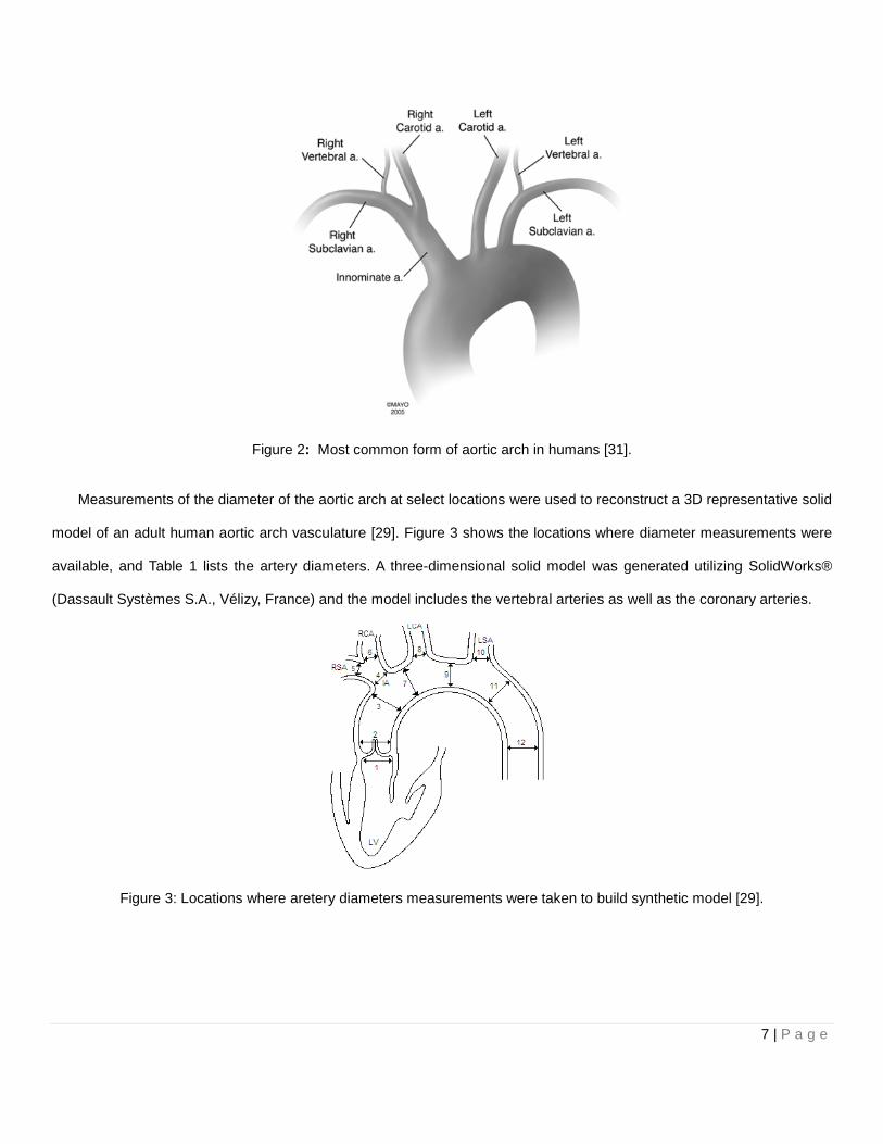
Figure 2: Most common form of aortic arch in humans
Measurements of the diameter of the aortic arch at select locations
model of an adult human aortic arch vasculature
available, and Table 1 lists the artery diameters.
(Dassault Systèmes S.A., Vélizy, France) and the model includes the vertebral arteries as well as the coronary arteries.
Figure 3: Locations where aretery diameters measurements were
Most common form of aortic arch in humans [31].
Measurements of the diameter of the aortic arch at select locations were used to reconstruct a
vasculature [29]. Figure 3 shows the locations where diameter measurement
artery diameters. A three-dimensional solid model was generated utilizing Solid
and the model includes the vertebral arteries as well as the coronary arteries.
Locations where aretery diameters measurements were taken to build synthetic model
7 | P a g e
construct a 3D representative solid
shows the locations where diameter measurements were
dimensional solid model was generated utilizing SolidWorks®
and the model includes the vertebral arteries as well as the coronary arteries.
taken to build synthetic model [29].

8 | P a g e
Table 1: Artery diameters at locations identified in Figure 3.
Location Diameter [mm]
1 24.80
2 29.00
3 25.00
4 12.40
5 8.00
6 7.40
7 21.80
8 7.40
9 21.80
10 7.40
11 21.40
12 20.00
Figure 4: The complete aortic bed solid model including vertebral and coronary arteries generated for the CFD model.
Standard LVAD Configuration
LVADs are implanted by means of surgical procedure. The procedure consists of connecting an inflow cannula from
the apex of the left ventricle to the LVAD, and
adults, the LVAD outflow cannula is typically
wall of the ascending aorta.
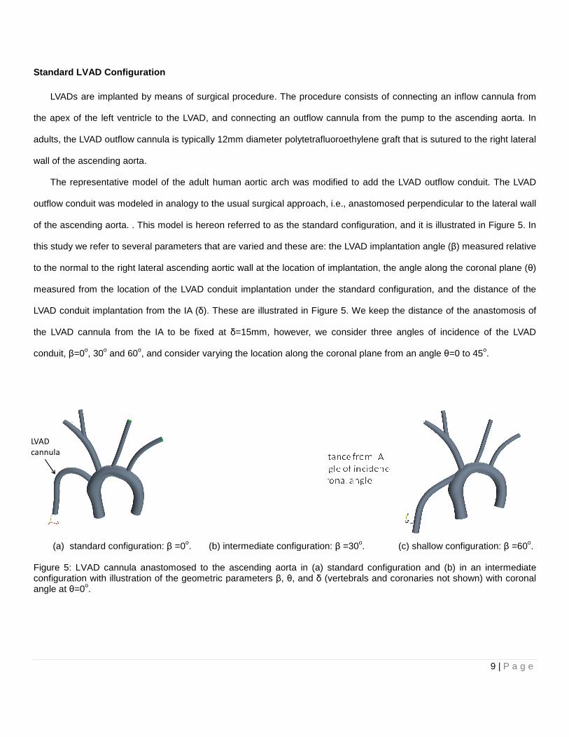
The representative model of the adult human aortic arch was modified to add the LVAD outflow conduit. The LVAD
outflow conduit was modeled in analogy to the usual surgical approach, i.e.,
of the ascending aorta. . This model is hereon referred to as the standard configuration, and it is illustrated in
this study we refer to several parameters that are varied and these are: the LVAD implantation angle (
to the normal to the right lateral ascending aortic wall
measured from the location of the LVAD conduit implantation under the standard configuration
LVAD conduit implantation from the IA (δ). These are
the LVAD cannula from the IA to be fixed at
conduit, β=0o, 30o and 60o, and consider varying the location along the coronal plane from an angle
(a) standard configuration: β =0o. (b) intermediate configuration
Figure 5: LVAD cannula anastomosed to the ascending aorta in (a) standard configuration and (b) in an intermediate configuration with illustration of the geometric parameters angle at θ=0o.
LVAD
cannula
LVADs are implanted by means of surgical procedure. The procedure consists of connecting an inflow cannula from
the apex of the left ventricle to the LVAD, and connecting an outflow cannula from the pump
typically 12mm diameter polytetrafluoroethylene graft that is sutured to the
The representative model of the adult human aortic arch was modified to add the LVAD outflow conduit. The LVAD
d in analogy to the usual surgical approach, i.e., anastomosed perpendicular to the
is hereon referred to as the standard configuration, and it is illustrated in
several parameters that are varied and these are: the LVAD implantation angle (
aortic wall at the location of implantation, the angle along the coronal plane (
measured from the location of the LVAD conduit implantation under the standard configuration
). These are illustrated in Figure 5. We keep the distance of the anastomosis of
the LVAD cannula from the IA to be fixed at δ=15mm, however, we consider three angles of
, and consider varying the location along the coronal plane from an angle
(b) intermediate configuration: β =30o. (c) shallow configuration:
: LVAD cannula anastomosed to the ascending aorta in (a) standard configuration and (b) in an intermediate configuration with illustration of the geometric parameters β, θ, and δ (vertebrals and coronaries not shown)
9 | P a g e
LVADs are implanted by means of surgical procedure. The procedure consists of connecting an inflow cannula from
the pump to the ascending aorta. In
graft that is sutured to the right lateral
The representative model of the adult human aortic arch was modified to add the LVAD outflow conduit. The LVAD
perpendicular to the lateral wall
is hereon referred to as the standard configuration, and it is illustrated in Figure 5. In
several parameters that are varied and these are: the LVAD implantation angle (β) measured relative
the angle along the coronal plane (θ)
measured from the location of the LVAD conduit implantation under the standard configuration, and the distance of the
. We keep the distance of the anastomosis of
three angles of incidence of the LVAD
, and consider varying the location along the coronal plane from an angle θ=0 to 45o.
(c) shallow configuration: β =60o.
: LVAD cannula anastomosed to the ascending aorta in (a) standard configuration and (b) in an intermediate (vertebrals and coronaries not shown) with coronal
10 | P a g e
(a) β= 0o (b) β= 30o (c) β= 60o
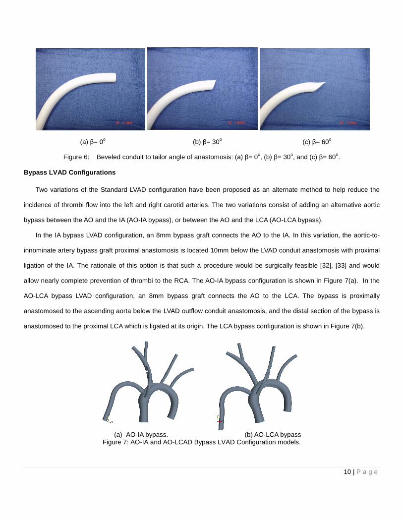
Figure 6: Beveled conduit to tailor angle of anastomosis: (a) β= 0o, (b) β= 30o, and (c) β= 60o.
Bypass LVAD Configurations
Two variations of the Standard LVAD configuration have been proposed as an alternate method to help reduce the
incidence of thrombi flow into the left and right carotid arteries. The two variations consist of adding an alternative aortic
bypass between the AO and the IA (AO-IA bypass), or between the AO and the LCA (AO-LCA bypass).
In the IA bypass LVAD configuration, an 8mm bypass graft connects the AO to the IA. In this variation, the aortic-to-
innominate artery bypass graft proximal anastomosis is located 10mm below the LVAD conduit anastomosis with proximal
ligation of the IA. The rationale of this option is that such a procedure would be surgically feasible [32], [33] and would
allow nearly complete prevention of thrombi to the RCA. The AO-IA bypass configuration is shown in Figure 7(a). In the
AO-LCA bypass LVAD configuration, an 8mm bypass graft connects the AO to the LCA. The bypass is proximally
anastomosed to the ascending aorta below the LVAD outflow conduit anastomosis, and the distal section of the bypass is
anastomosed to the proximal LCA which is ligated at its origin. The LCA bypass configuration is shown in Figure 7(b).
(a) AO-IA bypass. (b) AO-LCA bypass
Figure 7: AO-IA and AO-LCAD Bypass LVAD Configuration models.

11 | P a g e
CFD MODEL
The CFD analyses reported in this paper were conducted with the commercially available CFD software Fluent 6.3
(ANSYS Corp., Canonsburg, PA, USA) [34]. The flow field is resolved by numerically solving the mass and momentum
conservation equations, which neglecting gravitational and other body forces, are:
0 ( )V
V and V V pt
∂ρ ρ τ∂
∇ ⋅ = + ⋅∇ = −∇ + ∇ ⋅�
� � �
(1)
Where, ρ is the mass density, V is the velocity, and � is the viscous stress tensor. Blood is effectively an incompressible
fluid. We utilized a density of 31060 /kg mρ = and a dynamic viscosity of 20.04 /Ns mµ = . The models were meshed
in Fluent meshing software package Gambit utilizing typically approximately 2 million tetrahedral cells. This level of
discretization was determined to be adequate to ensure grid independence. This was established in a mesh convergence
study targeting the outlet mean velocity and pressures as measures of grid independence for models discretized with an
increasingly finer mesh as will be discussed in the results section where results from grid convergence studies are
provided. For our studies, a representative sick adult heart was modeled. The flow field was modeled as steady with a
cardiac ejection of 1 liter/min and a VAD flow rate of 3 liters/min resulting in a total flow of 4 liters/min. Continuous flow
LVADs significantly reduce pulsatility and, in contrast to the cardiac pulse, produce a steady flow baseline flow with a
small periodicity. A safe pulse pressure greater than 15mmHg has been suggested to open the aortic valve. With a
baseline pressure of 100mmHg, a 20mmHg pulse provides a 20% contribution to the flow. It is also noted that VAD
manufacturers recommend that VADs should be operated with a pulsatility index of 30%, with the pulsatility index defined
as the difference between the maximum and minimum over the baseline value of the flow rate waveform. Although not a
small perturbation, it is small enough, to assume that the steady baseline flow Lagrangian particle trajectories can yield
useful information that lends support to our hypothesis. The k-ω SST model was utilized to account for turbulence with 5%
turbulence imposed at the inlet of the LVAD and 5% turbulence at the inlet of the ascending aorta. For the outlets, a flow-
split boundary condition was applied to the different arteries assigning a fixed percentage of the total flow to each outlet
boundary with the various flow splits assignments shown in Figure 8.

12 | P a g e
Figure 8: AO-IA bypass model with assigned flow splits.
LAGRANGIAN PARTICLE TRACKING MODEL
In order to analyze the trajectory of the blood clots in the different aortic-arch LVAD models, the trajectories of
particles with similar properties to those of thrombi are computed using a mixed Eulerian-Lagrangian approach where
thrombi trajectories are predicted using a Lagrangian model in a Newtonian Fluid. In this approach, the discrete phase
(particles/thrombi) is uncoupled from the continuous phase (carrier/blood). Particles with properties analogous to the
blood clots are introduced in the computational domain (at the LVAD conduit inlet plane) and their trajectories are
governed by the momentum conservation equation (Newton’s second law of motion) in terms of the particle velocity, pV→
,
and sum of the forces acting on the particle:
p
body surfacep
dVm F F
dt
→→ →
= +∑ ∑ (2)
The only body force that is accounted is that due to added mass effect, with the buoyancy force neglected due to the
fact the density ratio between blood and the thrombus particle is ρparticle/ρblood=1.097, with the density of thrombi taken from
the literature to be 1117pρ = kg/m3.

13 | P a g e
For a particle of density, pρ , diameter, pd , entrained by a fluid of viscosity, fµ , flowing at a mean velocity, U, within a
conduit of diameter, D, the Stokes number (St) defined as the ratio of the particle response time,
2p p
pf
dρτ
µ= , to the
convective time scale, f
D
Uτ = , that
2
18p p p
f f
d DSt
U
τ ρτ µ
= = . The Stokes number is an indicator as to whether the surface
forces entraining the particle dominate over the particle momentum and the particle essentially follows the streamlines (St
<1) or the momentum of the particle dominates over the forces acting on the particle and the particle can deviate from the
streamlines (St>1) as these bend around an obstacle or in a conduit. With a diameter of 30mm in the ascending aorta
and a total flow of 4 liters/min, the Stokes number for the particles in the range of 1mm-6mm span the ranges of St=0.051-
1.828 while in the VAD conduit with a flow rate of 3 liters/min and a diameter of 12mm, the Stokes number range is
St=0.595-21.45. Thus, in general, the paths of thrombi of size greater than 2mm deviate significantly from the streamlines
in this model.
The main surface force in the model is that due to viscous drag force caused by the relative velocity of the particles
with respect to the continuous phase. The drag force for a given particle is given by:
1
2d d p p s sF C A V Vρ=� � �
(3)
Where Cd is the drag coefficient, Ap is the particle cross section, and the particle slip velocity is sV→
. The drag coefficient
can be estimated using correlations for drag on spherical particles. Such a correlation is available in Fluent, or
alternatively, user defined functions can be utilized to implement a desired correlation. The other surface forces, such as
the Saffman lift force and the Faxen correction due to pressure are neglected as they are not expected to significantly
affect the thrombi trajectories.
There is little about the size distribution of thrombi encountered in VAD-induced thrombi. Clinical experience
however suggests that thrombi encountered in such events have diameters that range from 2mm-5mm. Moreover,
interaction between thrombi and arterial walls are due to a complex set of biochemical and biophysical factors such as
arterial wall roughness, chemical bond formation, surface reactivity, and re-suspension. In our analysis, we assume that
the collisions between thrombi and arterial walls are elastic (restitution coefficients equal to unity). Particles are allowed a
maximum residence time of 300s after which the solver removes them from the computational domain. This would occur

14 | P a g e
for instance when a particle is captured in a recirculation zone and unable to deviate from a streamline, in such a case
after 300s such a particle will be removed from the simulation. Three different thrombi diameters were used as the particle
diameters, 2mm, 4mm, and 5mm in the simulation. Ultimately, our model allows us to predict the general pattern as to
what type of thrombus posses a higher chance of flowing into the carotid and vertebral arteries and causing cerebral
embolisms.
OUTFLOW CONDUIT PLACEMENT OPTIMIZATION
There are several factors that can potentially affect the trajectory of thrombi generated inside the LVAD. For this study,
we consider geometric effects by varying size, position and orientation of the VAD outflow conduit implantation in order to
identify a configuration that minimizes the incidence of carotid, vertebral, and coronary embolism. Moreover, we
numerically analyze the effectiveness of a proposed aortic-to-IA artery bypass graft and an aortic-to-LCA bypass graft in
reducing the incidence of carotid, vertebral, and coronary embolization. Thus, the ultimate goal of this work is to establish
that the orientation of the LVAD conduit significantly affects the incidence of cerebrovascular embolization and to suggest
that there exists an optimal placement and orientation of the LVAD outflow conduit and possibly the addition of an aortic-
to-IA an aortic-to-LCA bypass graft that will significantly reduce the occurrence of thromboembolism in the carotid and
vertebral arteries. We consider three values for the angle, β= 0o, 30o and 60o, and also consider varying the coronal angle
placement, θ. In all cases, we keep the distance of the VAD conduit anastomosis from the IA at δ=15mm. All of these
variations correspond to surgically achievable configurations.
RESULTS AND DISCUSSION
The main objective of the CFD simulations is to determine whether changing the LVAD outflow cannula angle, and/or
adding an aortic bypass significantly affected the trajectory of thrombi emanating from the LVAD conduit. That is we aim to
establish that the geometric configuration of the LVAD conduit anastomoses is an important consideration in determining
eventual stroke events, thus establishing the possibility of searching for an optimal LVAD conduit implantation
configuration that reduces stroke. No study had attempted to study trajectory of thrombi inside the aortic arch bed and
how these trajectories change depending on the implant geometry and thrombi diameter. In our work, we utilized CFD to
investigate the trajectories of representative 2mm, 4mm, and 5mm diameter randomly released particles at the LVAD
cannula inlet plane over a series of 5 trials for each particle diameter. We then computed the percentage of released
particles of a given diameter reaching the critical arteries as well as the pooled statistics.

15 | P a g e
We first comment on results from initial studies, reported in part in [35], in which we investigated fifteen geometric
configurations for a simple model that did not include vertebrals or coronaries with a release of a moderate number of
particles (30 per trial). The results obtained in these studies indicate that there is indeed a significant relation between the
LVAD implant geometry configuration and the number of thrombi flowing through the right and left carotid arteries with as
much a 50% (pooled statistic) variation found between configurations. Although the incidence of thromboembolism to the
carotids was never completely eliminated under any one of the considered configurations, the preliminary study
corroborated the hypothesis that there is an optimal LVAD implant configuration that can help reduce the number of
thrombi flowing into the carotid arteries.
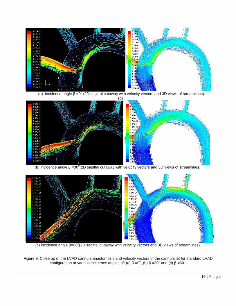
Varying the LVAD outflow conduit angle significantly affects the flow field within the aortic arch. Lower values of LVAD
cannula incidence angle β tend to create flows where the cannula outflow jet impinges on the contra-lateral wall of the
ascending aorta, thus creating re-circulation zones and stagnation point zones with low wall shear stresses that have
been associated with platelet activation [9]-[11] and are possible thrombogenic sites.
Figure 9 shows velocity vectors of the Standard LVAD Configuration for values of β of 0o, 30o, and 60o for a sagittal
plane as well as 3D streamlines produced by these flows. Increasing the value of β obviously reduced the impingement on
the contra-lateral wall of the ascending aorta, as well as the observed re-circulation where thrombi have a tendency to get
captured by the large recirculation zones, increasing their potential to be captured by the inflow to the IA. It is also
interesting to note the nature of the complex 3D flow field generated by the confluence of the jet emanating from the LVAD
cannula and the flow ejected by the left ventricle, the complex nature of the impingement flow at the contra-lateral wall of
the ascending aorta, as well as the rotational flow observed in the descending aorta. A large recirculation zone is
observed on the ventral aortic arch and this feature also has the tendency to trap particles that may subsequently be
ingested by the left carotid or innominate arteries. However, although increasing the angle β helped to reduce the
impingement on the ascending aorta, as well as the re-circulation, this had the negative effect of increasing thrombi flow,
particularly to the LCA as the flow is now directed more towards the take-off of the LCA. As the value of β increased, so
did the number of thrombi flowing into the LCA, as the thrombus were directed preferentially towards the take-off of that
vessel, however, that slight increase was accompanied by a decrease of thrombi reaching the RCA and, consequently, an
overall reduction in the incidence of thrombi reaching critical vessels. It is also worth noting that the level of the
impingement flow at the ascending aorta is reduced with an accompanying reduction in the recirculation close to the IA
16 | P a g e
(a) incidence angle β =0o (2D sagittal cutaway with velocity vectors and 3D views of streamlines).
(b)
(b) incidence angle β =30o(2D sagittal cutaway with velocity vectors and 3D views of streamlines).
(c) incidence angle β=60o(2D sagittal cutaway with velocity vectors and 3D views of streamlines).
Figure 9: Close up of the LVAD cannula anastomosis and velocity vectors of the cannula jet for standard LVAD configuration at various incidence angles of: (a) β =0o, (b) β =30o and (c) β =60o.
17 | P a g e
take-off and that the recirculation at the proximal aortic arch is also reduced. At a large angle of β, the features of re-
circulating flow patterns and impingement flow are essentially eliminated.
The possibility of adding an alternative aortic bypass was considered as a way to capitalize on the benefits of higher
values of β, while still reducing the number of thrombi flowing through the RCA and LCA. Models with the IA and LCA
bypasses suggested that it was possible to reduce the number of thrombi flowing into these arteries by routing some of
the blood flow from the aortic root into the IA and LCA, respectively. The advantage of the alternative aortic bypass is that
due to its location, i.e., it mainly feeds from blood being ejected from the heart. This blood has a lower chance of
containing thrombi in comparison to the blood being pumped by the LVAD. However, the addition of the IA Bypass, or the
LCA Bypass did not necessarily reduce overall the number of thrombi flowing through the RCA and LCA. The reason is
that the behavior of thrombi changes greatly as the thrombi diameter changes: smaller thrombi have Stokes numbers
based on the aorta diameter that is less than one and tend to follow the flow, while larger diameter particles have Stokes
numbers that are larger than one and their trajectory can deviate from that of the mean flow as the mean flow changes
direction. Therefore a particular configuration might be an optimum configuration that minimizes 2mm thrombi flow to the
carotid and vertebral arteries, while allowing a large number of 5mm thrombi to flow through these same arteries.
Guided by the results of our previous studies, we focused on a reduced set of configurations that yielded promising
result. These were analyzed for the complete aortic bed model that included both vertebral and coronary arteries. We
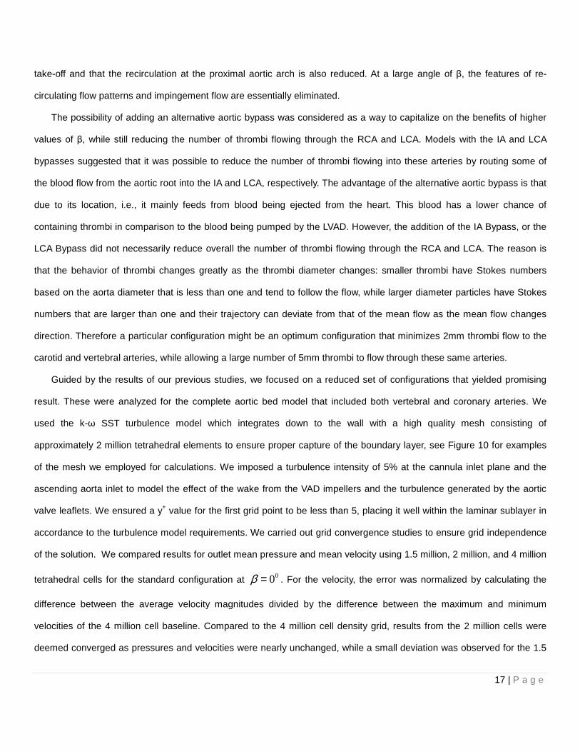
used the k-ω SST turbulence model which integrates down to the wall with a high quality mesh consisting of
approximately 2 million tetrahedral elements to ensure proper capture of the boundary layer, see Figure 10 for examples
of the mesh we employed for calculations. We imposed a turbulence intensity of 5% at the cannula inlet plane and the
ascending aorta inlet to model the effect of the wake from the VAD impellers and the turbulence generated by the aortic
valve leaflets. We ensured a y+ value for the first grid point to be less than 5, placing it well within the laminar sublayer in
accordance to the turbulence model requirements. We carried out grid convergence studies to ensure grid independence
of the solution. We compared results for outlet mean pressure and mean velocity using 1.5 million, 2 million, and 4 million
tetrahedral cells for the standard configuration at 00β = . For the velocity, the error was normalized by calculating the
difference between the average velocity magnitudes divided by the difference between the maximum and minimum
velocities of the 4 million cell baseline. Compared to the 4 million cell density grid, results from the 2 million cells were
deemed converged as pressures and velocities were nearly unchanged, while a small deviation was observed for the 1.5
18 | P a g e
million cell grid, see Figure 11 and Figure 12. Similar trends were seen in other configurations. As such, we report the
results from a grid density of nearly 2 million cells in all cases.
(a) close-up of aortic arch mesh with bypass to LCA.
(a) junction of IA, RCA and RVA. (c) cut-away of ascending aorta and cornaries.
Figure 10: Views of the mesh utilized in reported computations: approximately 2 million cells.
Figure 11: Mean pressure measured at outlets as mesh density varies.

19 | P a g e
Figure 12: Mean velocity measured at outlets as mesh density varies.
We randomly released nearly 300 particles at the inlet plane of the LVAD cannula and for each particle diameter, see
Figure 13. This was repeated five times for each particle diameter. The mean and standard deviation of the percentage of
released particles released reaching the LCA, RCA and VA were computed for each diameter using a 95% confidence
level. Moreover, an overall (pooled) static of the mean and standard deviation was also computed so as to better
characterize an overall assessment of a given configuration. If a particular thrombus diameter has a high embolization
probability, this will be reflected in a high overall probability, while a low overall probability will reflect consistently low
embolization probabilities across all thrombus diameters. A time lapse of the particle paths of a subset of 50 particles
taken from the nearly 300 released at the inlet cannula is provided in Figure 14 for 2mm and a subset of 15 particles in
Figure 15 for 5mm diameter particles, while particle paths colored by residence time are provided in Figure 16. The
computed statistics for the predicted rates of embolization of the particles for a given diameter as well as pooled statistics
are provided in Table 2 for several configurations we investigated in this paper.
Figure 13: Cannula inlet plane: location of particle release.
0
0.05
0.1
0.15
0.2
0.25
0.3
0.35
0.4
0.45
1350000 1850000 2350000 2850000 3350000 3850000
Vel
ocit
y M
agni
tude
(m
/s)
Number of Cells
Velocity Convergence
ao
cor_one
cor_two
da
lca
lsa
lvad
rca
rsa
va
LVAD
cannula
release
particles

20 | P a g e
Figure 14: A time lapse of the particle paths of a subset of 50 particles from the nearly 300 released at the inlet cannula for 2mm diameter particles.

21 | P a g e
Figure 15: A time lapse of the particle paths of a subset of 15 particles from the nearly 300 released at the inlet cannula for 5mm diameter particles.
22 | P a g e
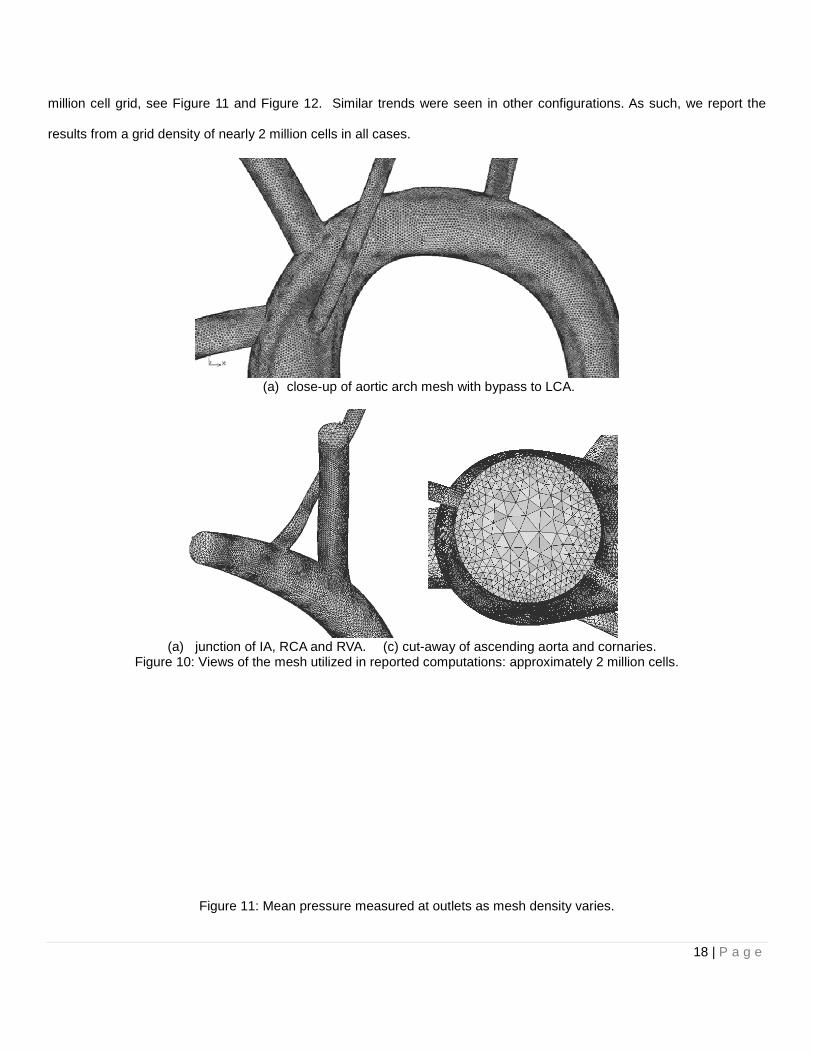
Figure 16: Particle paths colored by time of residence for a subset of 15 particles from the nearly 300 released at the inlet cannula for 2mm, 4mm, and 5mm diameter particles.
Table 2: Resulting statistics of k-ω SST model for AO bed with vetebrals and coronary arteries with
statistics computed at a 95% level of confidence. Configuration [5% inlet turbulence at LVAD cannula and AO]
2mm Thrombi [% reaching LCA, RCA & VA]
4mm Thrombi [% reaching LCA, RCA & VA]
5mm Thrombi [% reaching LCA, RCA & VA]
Overall [% reaching LCA, RCA & VA]
Standard β=00, θ=00, no bypass 18.14±3.69 21.24±2.66 25.05±3.18 21.48±3.2
Standard β =200, θ=00, no bypass 24.4±1.1 14.24±0.79 13.3±1.08 17.31±1
Standard β =300, θ=00, no bypass 22.12±1.27 15.37±2.85 14.92±4.71 17.47±3.26
IA Bypass β =300, θ=00 23.8±3.32 16.83±1.87 16.6±0.77 19.07±2.24
LCA Bypass β =300, θ=00 23.25±5.97 12.76±2.88 12.87±1.03 16.28±3.87
LCA Bypass β =300, θ=450 17.86±3.48 15.58±1.75 17.4±4.24 16.94±3.32
Standard β =600, θ=00, no bypass 12.91±1.95 10.45±1.43 9.63±1.13 11±1.54

23 | P a g e
The CFD simulations provide insight into the overall and particular rates of thromboembolization. In what we refer to
as the standard configuration with an angle of β=0, a major feature of the flow is a large recirculation zone and a
stagnation flow region as the jet emanates from the LVAD cannula. Thrombi of all diameters are trapped in that zone and
are susceptible to ingestion at the IA take-off. This is clearly seen in Figure 16 where the predominant path taken by all
thrombi is that leading to the IA and subsequently to the RCA and RVA leading to the highest embolization rates across
diameters and in terms of pooled statistics of all the configurations under consideration. Clearly, this is not a desirable
manner to implant the LVAD cannula. As the angle of implantation is increased to 200 and 300, the rate of embolization to
the RCA and RVA are reduced as the recirculation and impingement features of the flow field are reduced with a slight
accompanying increase in embolization to the LCA and LVA due to the redirection of the cannula jet towards the take-off
of the LCA and LSA. Overall, the rate of embolization is reduced by 20% over the standard configuration. Although
embolization rates of 2mm thrombi increased by 16%, the rates for 4mm and 5mm particles decreased by 29% and 40%
respectively. The increase of embolization of 2mm thrombi is due to the reflection of thrombi from the ventral wall of the
ascending aorta preferentially directed towards the intake of the IA as the angle is reduced. These thrombi have a low
Stokes number much smaller than one and thus generally follow the streamlines of the flow. Larger thrombi with Stokes
numbers close to and exceeding one have enough momentum not to be entrained by the mean flow to follow streamlines.
As such, their paths lead them away from the IA as can be clearly seen in Figure 14 - Figure 16, where the reduction of
thrombi reaching the IA, RCA and RVA is evident. With β=30o, with proximal ligation of the IA and with the addition of an
8mm diameter aortic-to-innominate artery bypass graft, with a proximal anastomosis located 10mm below the LVAD
conduit anastomosis, the overall incidence of thromboembolization was not reduced significantly. This is due to the fact
that the recirculation feature, although somewhat reduced, was still present at β=30o and thrombi caught in the
recirculation zone were still prone to be ingested by the inflow to the bypass ultimately reaching the RCA and RVA. An
alternative by-pass to the LCA with ligation of the LCA at the aortic arch did reduce the overall rate of embolization further
down to nearly 25% with slight reduction for 2mm diameter thrombi (<1% reduction) but more significant reduction for
4mm (~38% reduction) and 5mm thrombi (~52% reduction). Locating the LVAD conduit anastomosis to an angle of θ=45o
along the coronal plane with β=30o and with an LCA bypass did not significantly alter the overall thromboembolization rate
reduction obtained by an LCA bypass with β=30o configuration, however, the rates of thromboembolization across all
diameters were more uniformly reduced with an overall reduction of ~20% over the standard configuration.

24 | P a g e
Further increase of the angle of incidence of the cannula anastomosis to β=60o reduced the predicted overall rate of
thromboembolization by 50% with across-the-board reduction in rates of embolization for 2mm diameter thrombi (~28%
reduction), for 4mm (~50% reduction) and 5mm thrombi (~62% reduction). In this configuration, the jet from the cannula is
generally oriented to impinge just past the take-off of the LCA from the dorsal wall of the aorta. Smaller diameter thrombi
with small Stokes numbers are entrained away from the IA and are less subject to ingestion and consequently reaching
the RCA and RVA, while more susceptible to ingestion by the RCA. Overall, this leads to a slight decrease in embolization
of 2mm diameter thrombi. However, larger diameter thrombi with Stokes numbers greater than one adopt a trajectory that
leads them to impinge the dorsal aortic arch at locations between the LCA and RSA take-offs thereby reducing the
incidence of ingestion of these thrombi and leading to a significant overall reduction in predicted thromboembolisms to the
LCA and RVA.
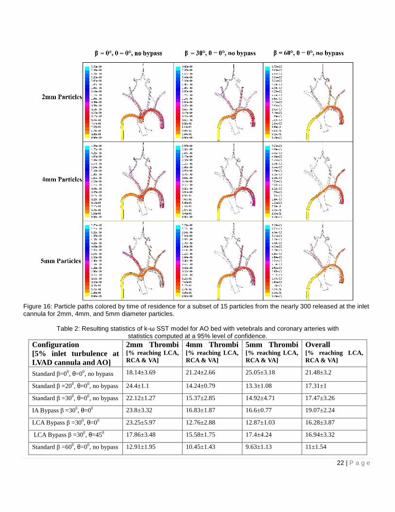
Comparative rates of predicted thromboembolization between the carotids and vertebral arteries provided in Figure 17
reveal that the predicted rates of embolization to the vertebral arteries remain fairly constant over all the configurations
under consideration at a rate of close to 5%. The embolization rates to the carotids are higher ranging from nearly 18% in
the nominal configuration to a low of nearly 7% in the best configuration. Of the two, the predicted embolization to the
carotids is the most affected by the geometric configuration of the LVAD conduit implantation. It can be reasoned that the
embolization to the vertebrals is less sensitive to changes in LVAD implantation configuration is due to their more distal
location relative to the inlet of the IA and LSA, allowing the flow to become more organized, rendering them less prone to
be affected by variations caused in the main flow by cannula orientation. The vertebrals are also smaller diameter vessels
that are oriented nearly normal to the IA or LSA. The carotids on the other hand are fed by flow which directly is affected
by variations of the cannula orientation in the case of the LCA which takes off the lateral wall of the aorta and the RCA
which is affected by the secondary flows present at the take off of the IA and is oriented as a shallow angle presenting a
large acceptance angle to the incoming flow.
25 | P a g e
Figure 17: Comparative rates of embolization to the carotids and vertebral arteries.
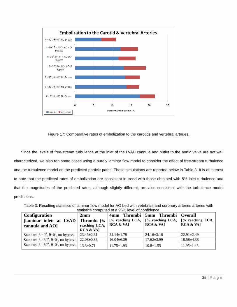
Since the levels of free-stream turbulence at the inlet of the LVAD cannula and outlet to the aortic valve are not well
characterized, we also ran some cases using a purely laminar flow model to consider the effect of free-stream turbulence
and the turbulence model on the predicted particle paths, These simulations are reported below in Table 3. It is of interest
to note that the predicted rates of embolization are consistent in trend with those obtained with 5% inlet turbulence and
that the magnitudes of the predicted rates, although slightly different, are also consistent with the turbulence model
predictions.
Table 3: Resulting statistics of laminar flow model for AO bed with vetebrals and coronary arteries arteries with statistics computed at a 95% level of confidence.
Configuration [laminar inlets at LVAD cannula and AO]
2mm Thrombi [% reaching LCA, RCA & VA]
4mm Thrombi [% reaching LCA, RCA & VA]
5mm Thrombi [% reaching LCA, RCA & VA]
Overall [% reaching LCA, RCA & VA]
Standard β =00, θ=00, no bypass 23.45±2.31 21.14±1.79 24.16±3.16 22.91±2.49 Standard β =300, θ=00, no bypass 22.08±0.86 16.04±6.39 17.62±3.99 18.58±4.38 Standard β =600, θ=00, no bypass 13.3±0.71 11.75±1.93 10.8±1.55 11.95±1.48

26 | P a g e
CONCLUSIONS
In summary, CFD models of a representative human aortic arch with a LVAD implant were used to establish that the
geometric configuration of the LVAD conduit implantation affects possible thromboembolic events leading to stroke.
Furthermore, our study establishes that the concept of an optimal LVAD implant configuration that reduces the number of
thrombi flowing through the RCA and LCA is a viable engineering solution to the present problem posed by thrombus
formation in VAD-outfitted patients. By adjusting the angle at which the LVAD outflow cannula is sutured, and the
presence, or lack of an alternative aortic bypass, it was possible to quantify the probability of embolization for 2mm, 4mm,
and 5mm diameter thrombi. In addition, an overall thromboembolization probability was calculated from the individual
probabilities, and used to assess each LVAD implant configuration. Individual results showed that the behavior of 2mm
thrombus differs from the behavior of 4mm, or 5mm thrombi due to the range of Stokes numbers spanned by these
particles over the various flow configurations. For example, configurations that reduce the number of 2mm thrombi flowing
through the carotid arteries might not necessarily reduce the number of 4mm, or 5mm thrombi that flow through the RCA
and LCA. Our simulations on a representative aortic arch geometry reveals that it is possible to reduce the overall rate of
embolization of thrombi by nearly 50% with as much as a 60% reduction of incidence for larger thrombi.
Within the limitations of our model we have established that the LVAD implantation geometry is an important factor
and should be taken into consideration when implanting an LVAD. It is possible that other parameters such as distance of
the LVAD outflow cannula to the root of the IA, could affect the thrombi embolization probabilities. However, the results of
this study suggest that the risk of stoke may be significantly reduced by as much as 50% by tailoring the VAD implantation
by a simple surgical maneuver. We will soon report on ongoing follow-up studies utilizing patient specific aortic arch
anatomies extracted from CT scans, although preliminary results corroborating the findings reported in this paper can be
found in [36]. The results of this line of research may ultimately lead to techniques that can be used to estimate the
optimal LVAD configuration in a patient specific manner by pre-operative imaging.

27 | P a g e
NOMENCLATURE
Ap particle’s projected area
Cd drag Coefficient
Dp particle’s diameter
p pressure
�
V velocity vector
�
V s particle slip velocity vector
Rep particle’s Reynolds number
α LVAD outflow conduit suture angle
ρ blood density
ρp particle’s density
µ blood viscosity
∇ gradient
∇ ⋅ divergence
REFERENCES
[1] Lietz K, Long JW, Kfoury AG, Slaughter MS, Silver MA, Milano CA, Rogers JG, Miller LW, Deng M,
Naka Y, Mancini D. Impact of center volume on outcomes of left ventricular assist device
implantation as destination therapy: analysis of the Thoratec HeartMate Registry, 1998 to 2005,”
Circ Heart Fail, 2009 Jan;2(1):3-10.
[2] Pal JD, Piacentino V, Cuevas AD, Depp T, Daneshmand MA, Hernandez AF, Felker GM, Lodge
AJ, Rogers JG, Milano CA.,”Impact of left ventricular assist device bridging on posttransplant
Outcomes,” Ann Thorac Surg., 2009 Nov;88(5):1457-61; discussion 1461.
[3] Goldstein D.J., Oz M.C., and Rose E. “Implantable left ventricular assist devices,” N. England J.
Med. 1998; 339:1522-33 and Stroke,1997, 28:2453-6.
[4] Lazar RM, Shapiro PA, Jaski BE, Parides MK, Bourge RC, Watson JT, Damme L, Dembitsky W,
28 | P a g e
Hosenpud JD, Gupta L, Tierney A, Kraus T, Naka Y.,”Neurological events during long-term mechanical circulatory
support for heart failure: the Randomized Evaluation of Mechanical Assistance for the Treatment of Congestive
Heart Failure (REMATCH) experience,” Circulation, 2004 25;109(20):2423-7.
[5] Frazier OH, Kirklin James K., Mechanical circulatory support, ISHLT Monograph series 1, 2006,
pp. 1-8, Elsevier. United States of America
[6] Slater JP, Rose EA, Levin HR, Frazier OH, Roberts JK, Weinberg AD, Oz MC., ”Low
thromboembolic risk without anticoagulation using advanced-design left ventricular assist Devices,” Circulation,
1995;1;92(9 Suppl):II467-71.
[7] Ruygrok PN, Esmore DS, Alison PM, Finucane KA, McGuinness SP, McGeorge AD, Negri J, Jones K, Gibbs HC.,
“Pediatric experience with the VentrAssist LVAD,” Ann Thorac Surg., 2008, Vol.86(2), pp. 622-626.
[8] Miller LW, Pagani FD, Russell SD, et al. ,”Use of a continuous-flow device in patients awaiting
heart Transplantation,” N Engl J Med, 2007, Vol. 357, pp. 885–896.
[9] Pagani FD, Miller LW, Russell SD, Aaronson KD, John R, Boyle AJ, Conte JV, Bogaev RC,
MacGillivray TE, Naka Y, Mancini D, Massey HT, Chen L, Klodell CT, Aranda JM, Moazami N,
Ewald GA, Farrar, Frazier OH, “Extended Mechanical Circulatory Support With a Continuous-
Flow Rotary Left Ventricular Assist Device,” Journal of the American College of Cardiology,
Vol. 54, No. 4, 2009.
[10] John R., “Current axial-flow devices--the HeartMate II and Jarvik 2000 left ventricular assist
devices,” Semin Thorac Cardiovasc Surg., 2008 Fall;20(3):264-72.
[11] Laufer G, Noon GP, DeBakey M, Wolner E, Wieselthaler GM, Schima H, Hiesmayr M, Pacher
R., “First Clinical Experience With the DeBakey VAD Continuous-Axial-Flow Pump for Bridge to
Transplantation,” Circulation 2000;101;356-359.
[12] Slaughter MS, Rogers JG, Milano CA, Russell SD, Conte JV, Feldman D, Sun B, Tatooles AJ,
Delgado RM 3rd, Long JW, Wozniak TC, Ghumman W, Farrar DJ, Frazier OH; HeartMate II
Investigators,” Advanced heart failure treated with continuous-flow left ventricular assist device,”
N Engl J Med., 2009 Dec 3;361(23):2241-51.
[13] Mark S. Slaughter, M.D., Joseph G. Rogers, M.D., Carmelo A. Milano, M.D., Stuart D. Russell,
M.D., John V. Conte, M.D., David Feldman, M.D., Ph.D., Benjamin Sun, M.D., Antone J.

29 | P a g e
Tatooles, M.D., Reynolds M. Delgado, III, M.D., James W. Long, M.D., Ph.D., Thomas C.
Wozniak, M.D., Waqas Ghumman, M.D., David J. Farrar, Ph.D., and O. Howard Frazier, M.D.,
for the HeartMate II Investigators, “Advanced Heart Failure Treated with Continuous-Flow Left
Ventricular Assist Device,” N. Engl J. Med 361;23, pp. 2241-2251.
[14] Radovancevic B, Vrtovec B, de Kort E, et al.,”End-organ function in patients on long- term
circulatory support with continuous- or pulsatile-flow assist devices,“ J. Heart Lung Transplant.,
2007;26: 815– 8.
[15] Davies RR, Russo MJ, Hong KN, O'Byrne ML, Cork DP, Moskowitz AJ, Gelijns AC, Mital S,
Mosca RS, Chen JM.,”The use of mechanical circulatory support as a bridge to transplantation
in pediatric patients: an analysis of the United Network for Organ Sharing database,” J. Thorac
Cardiovasc. Surg., 2008 Feb;135(2):421-7, 427.e1.
[16] Russo MJ, Hong KN, Davies RR, Chen JM, Sorabella RA, Ascheim DD, Williams MR, Gelijns AC,
Stewart AS, Argenziano M, Naka Y.,”Posttransplant survival is not diminished in heart transplant
recipients bridged with implantable left ventricular assist devices,” J Thorac Cardiovasc Surg., 2009
Dec;138(6):1425-32.e1-3.
[17] Thoennissen NH, Allroggen A, Ritter M, Dittrich R, Schmid C, Schmid HH, Ringelstein EB, Nabavi
DG.,”Influence of inflammation and pump dynamic on cerebral microembolization in patients with
Continuous-Flow DeBakey LVAD,” ASAIO J., 2006 May-Jun;52(3):243-7.
[18] Schmid C, Weyand M, Nabavi DG, Hammel D, Deng MC, Ringelstein EB, Scheld HH.,”Cerebral
and systemic embolization during left ventricular support with the Novacor N100 device,” Ann.
Thorac Surg., 1998 Jun;65(6):1703-10.
[19] Radovancevic R, Matijevic N, Bracey AW, Radovancevic B, Elayda M, Gregoric ID, Frazier OH.
Increased leukocyte-platelet interactions during circulatory support with left ventricular assist
devices. ASAIO J. 2009 Sep-Oct;55(5):459-64.
[20] Sandner SE, Zimpfer D, Zrunek P, Steinlechner B, Rajek A, Schima H, Wolner E, Wieselthaler GM.
“Low molecular weight heparin as an alternative to unfractionated heparin in the immediate
postoperative period after left ventricular assist device implantation,” Artif Organs, 2008,
Vol. 32(10), pp. 819-822.

30 | P a g e
[21] Meuris B, Arnout J, Vlasselaers D, Schetz M, Meyns B.,”Long-term management of an implantable
left ventricular assist device using low molecular weight heparin and antiplatelet therapy: a possible
alternative to oral anticoagulants,” Artif Organs, 2007;31(5):402-5.
[22] Tsukui H, Abla A, Teuteberg JJ, McNamara DM, Mathier MA, Cadaret LM, Kormos RL.,
“Cerebrovascular accidents in patients with a ventricular assist device,” J Thorac Cardiovasc Surg.
2007;134(1):114-23.
[23] May-Newman, K.D. et al., “Effect of LVAD Outflow Conduit Insertion Angle on Flow
Through Native Aorta,” J. Med. Eng. Technol., 2004, 28(3): 105-109.
[24] Bluestein, D., et al., “Steady flow in an aneurysm model: correlation between fluid dynamics and
blood platelet deposition,” J Biomech Eng, 1996. 118(3): p. 280-6.
[25] Nobili, M., Sherrif,J., Morbiducci, U., Redaelli, A. and Bluestein, D.,”Platelet Activation Due to
Hemodynamic Shear Stresses: Damage Accumulation Model and Comparison to in Vitro
Measurements,” Am. Soc. Artificial Internal Organs Journal, 2008, pp. 64-72.
[26] Kima, T., Cheera, A.Y., and Dwyerb, H.A., “A simulated dye method for Flow-visualization with a
computational model for blood flow,” Journal of Biomechanics, 2004, 37: 1125–1136
[27] Tokuda, Y. et al., “Three-dimensional numerical simulation of blood flow in the aortic arch during
cardiopulmonary bypass,” European Journal of Cardio-thoracic Surgery, 2008, 33:pp. 164—167
[28] Drummond, A., Onur Dur, O., Pekkan, K. and Antaki, J., “Simulation of Optimal Surgical
Anastomosis of Pediatric Aortic Cannula,” ASME Paper SBC2008-193064, Proceedings of the
ASME 2008 Summer Bioengineering Conference (SBC2008) June 25-29, Marriott Resort, Marco
Island, Florida, USA.
[29] Geigy Scientific Tables – Vol. 5: Heart and Circulation, Lenter, C. (ed.), CIBA-Geigy Coporation, West Caldwell, New
Jersey, 1990, P. 87.
[30] N. Shahcheraghi, N. et al., “Unsteady and Three-Dimensional Simulation of Blood Flow in the
Human Aortic Arch,” ASME Journal of Biomechanical Engineering, 2002, 124: pp. 378-387.
[31] Layton K., Kallmes, D., Cloft, H., Lindell E., Cox, V. “Bovine Aortic Arch Variant in Humans: Clarification of a
Common Misnomer,” American Journal of Neuroradiology. 2006; 27: pp. 1541-1542.
[32] Noon GP, Loebe Matthias, Irwin S, Lafuente JA., “Implantation of the MicroMed DeBakey VAD,”

31 | P a g e
Operative Techniques in Thoracic and Cardiovascular Surgery, 2002;7(3):126-38.
[33] Hetzer R, Potapov EV, Weng Y, Sinawski H, Knollmann F, Komoda T, Hennig E, Pasic
M.,”Implantation of MicroMed DeBakey VAD through left thoracotomy after previous median
sternotomy operations,” Ann. Thorac. Surg. 2004;77(1):347-50.
[34] ANSYS, Fluent 6.3 User Guide, 2008.
[35] Andres F. Osorio, Alain J. Kassab, Eduardo A. Divo, I. Ricardo Argueta-Morales, and William M. DeCampli,
"Computational Fluid Dynamics Analysis of Surgical Adjustement of Ventricular Assist Device Implantation to
Minimize Stroke Risk, "ASME paper IMECE2009-12813, Proceedings of IMECE09 2009 ASME International
Mechanical Engineering Congress and Exposition, November 13-19, 2009, Lake Buena Vista, Florida.
[36] I. Ricardo Argueta-Morales, Reginald Tran, William Clark, Eduardo Divo, Alain Kassab, William M. DeCampli, "Use
of Computational Fluid Dynamics (CFD) to Tailor the Surgical Implantation of a Ventricular Assist Device (VAD): A
Patient-Specific Approach to Reduce Risk of Stroke," Presented at the Surgical Forum program at the American
College of Surgeons 96th Annual Clinical Congress, October 3-7, 2010, Washington, DC. (Abstract SF2010-10094),
Journal of the American College of Surgeons, Vo. 211, No. 3, Sept. 2010, p. S26