computational photography and video: warping, morphing and...
TRANSCRIPT
Computational Photography and Video:
Warping, Morphing and Mosaics
Prof. Marc Pollefeys
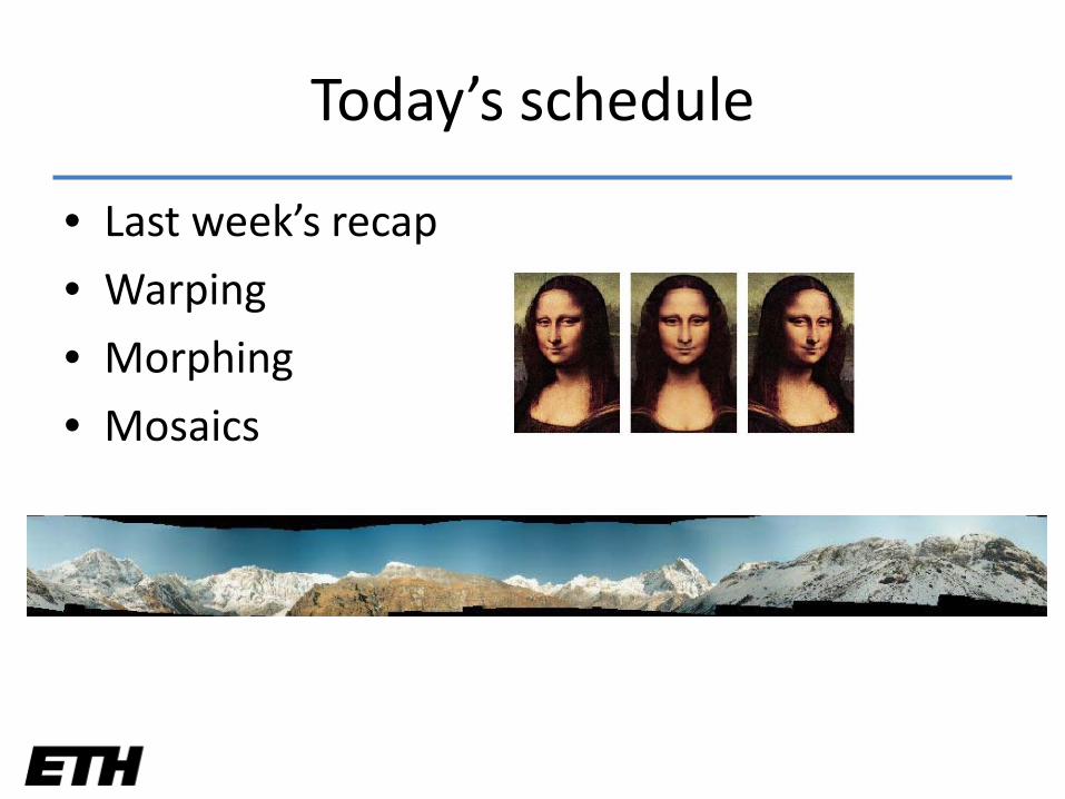
Today’s schedule
• Last week’s recap
• Warping
• Morphing
• Mosaics

Today’s schedule
• Last week’s recap
• Warping
• Mosaics
• Morphing
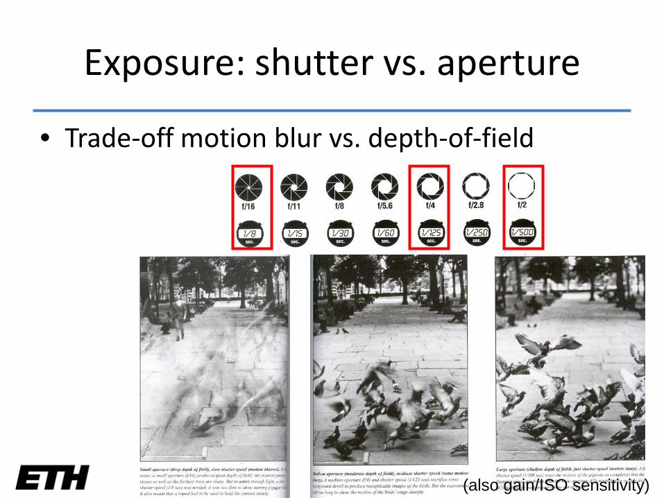
Exposure: shutter vs. aperture
• Trade-off motion blur vs. depth-of-field
(also gain/ISO sensitivity)
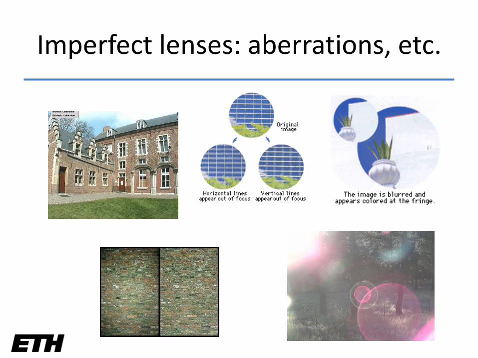
Imperfect lenses: aberrations, etc.
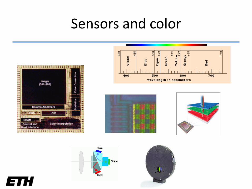
Sensors and color
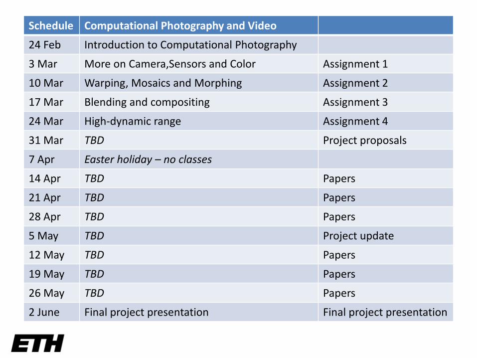
Schedule Computational Photography and Video
24 Feb Introduction to Computational Photography
3 Mar More on Camera,Sensors and Color Assignment 1
10 Mar Warping, Mosaics and Morphing Assignment 2
17 Mar Blending and compositing Assignment 3
24 Mar High-dynamic range Assignment 4
31 Mar TBD Project proposals
7 Apr Easter holiday – no classes
14 Apr TBD Papers
21 Apr TBD Papers
28 Apr TBD Papers
5 May TBD Project update
12 May TBD Papers
19 May TBD Papers
26 May TBD Papers
2 June Final project presentation Final project presentation

Today’s schedule
• Last week’s recap
• Warping
• Mosaics
• Morphing
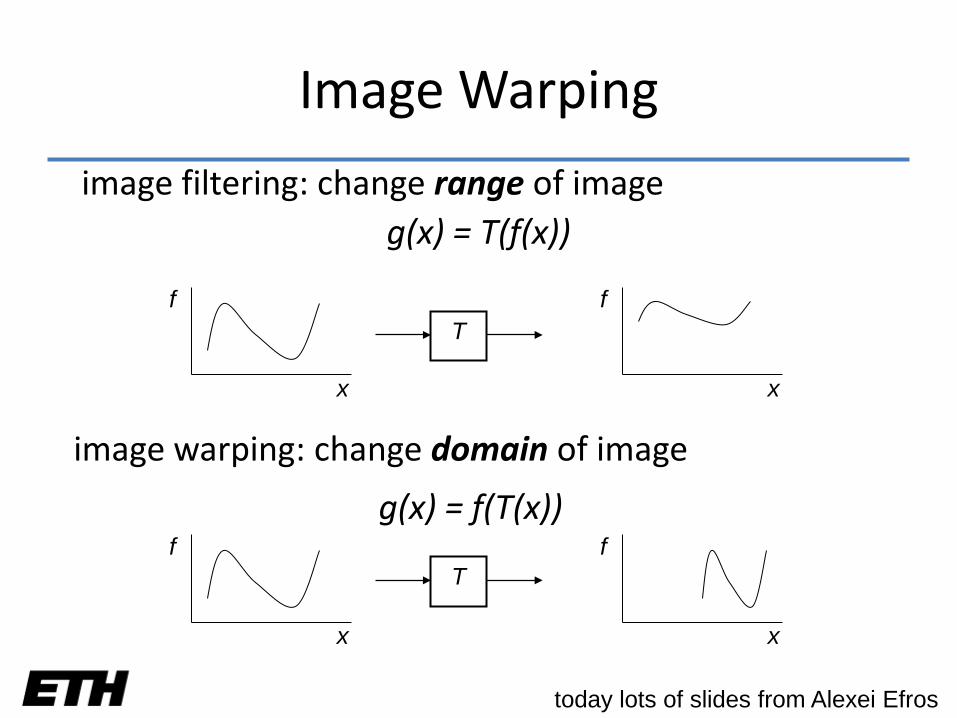
Image Warping
image filtering: change range of imageg(x) = T(f(x))
f
x
Tf
x
f
x
Tf
x
image warping: change domain of image
g(x) = f(T(x))
today lots of slides from Alexei Efros
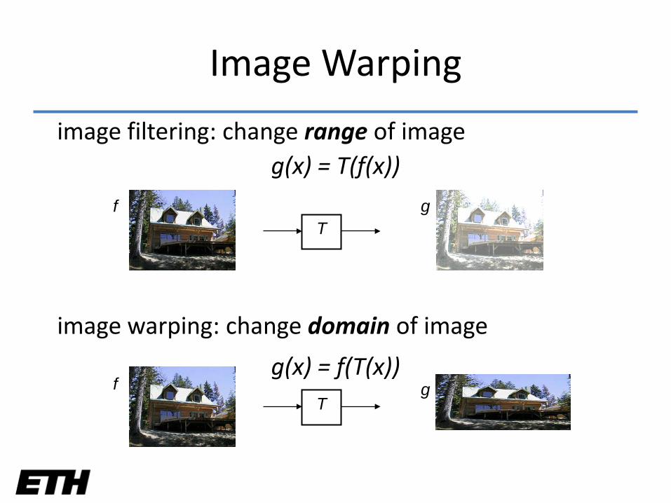
Image Warping
T
T
f
f g
g
image filtering: change range of imageg(x) = T(f(x))
image warping: change domain of image
g(x) = f(T(x))
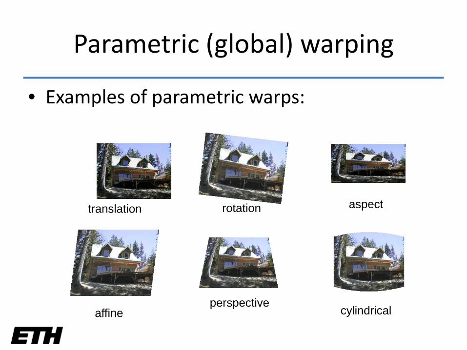
Parametric (global) warping
• Examples of parametric warps:
translation rotation aspect
affineperspective
cylindrical
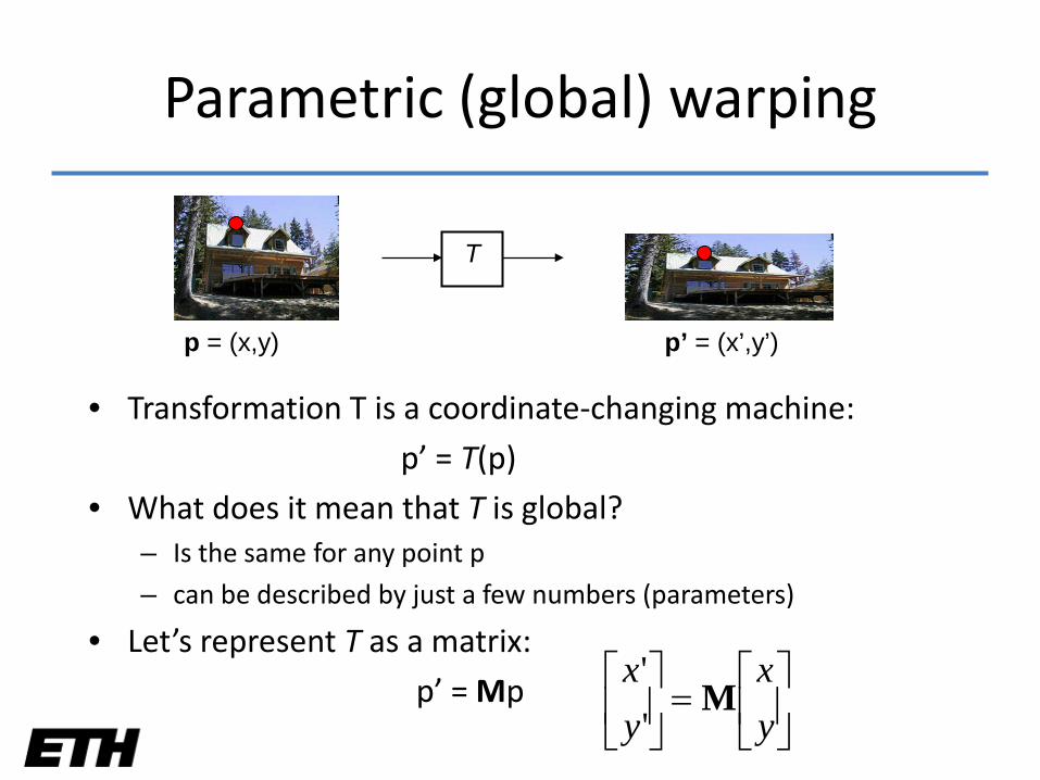
Parametric (global) warping
• Transformation T is a coordinate-changing machine:
p’ = T(p)
• What does it mean that T is global?– Is the same for any point p
– can be described by just a few numbers (parameters)
• Let’s represent T as a matrix:
p’ = Mp
T
p = (x,y) p’ = (x’,y’)
=
yx
yx
M''
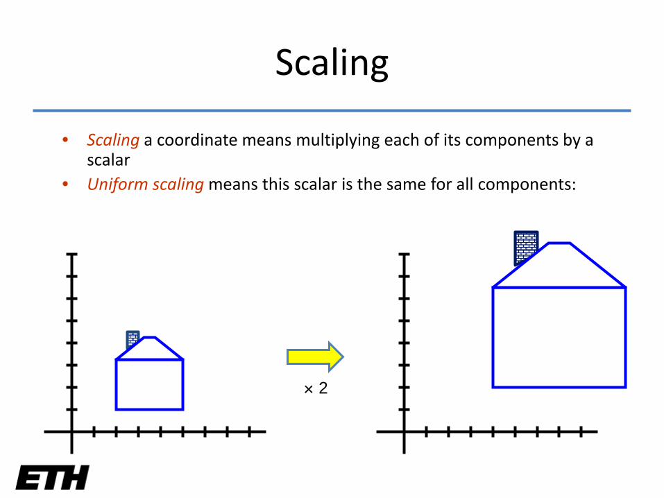
• Scaling a coordinate means multiplying each of its components by a scalar
• Uniform scaling means this scalar is the same for all components:
× 2
Scaling
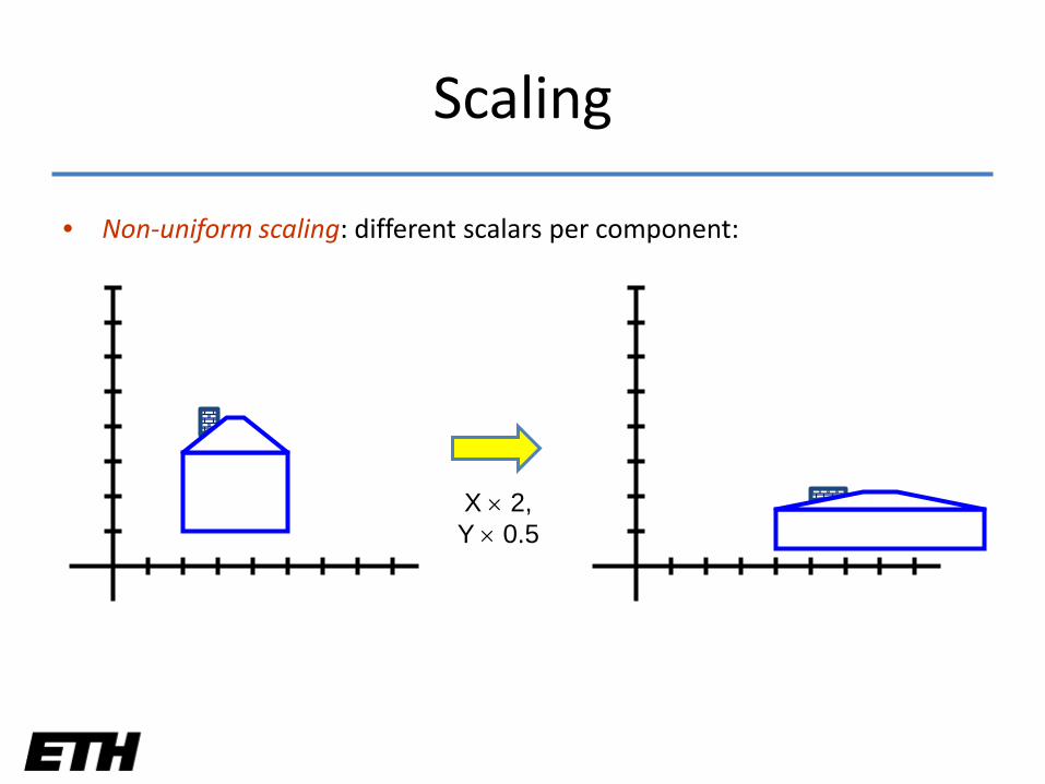
• Non-uniform scaling: different scalars per component:
X × 2,Y × 0.5
Scaling
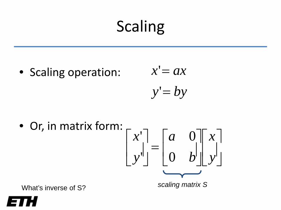
• Scaling operation:
• Or, in matrix form:
byyaxx
==''
=
yx
ba
yx
00
''
scaling matrix SWhat’s inverse of S?
Scaling
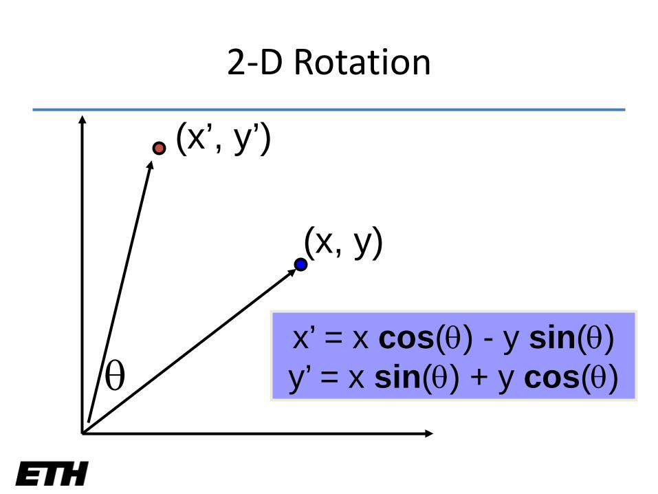
θ
(x, y)
(x’, y’)
x’ = x cos(θ) - y sin(θ)y’ = x sin(θ) + y cos(θ)
2-D Rotation
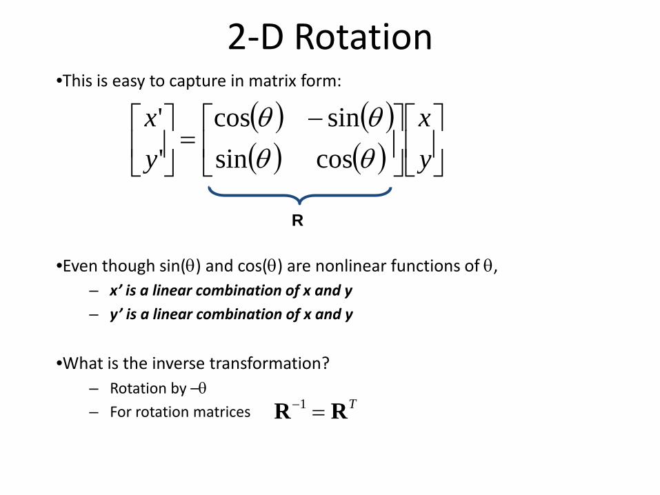
2-D Rotation•This is easy to capture in matrix form:
•Even though sin(θ) and cos(θ) are nonlinear functions of θ,– x’ is a linear combination of x and y
– y’ is a linear combination of x and y
•What is the inverse transformation?– Rotation by –θ– For rotation matrices
( ) ( )( ) ( )
−=
yx
yx
θθθθ
cossinsincos
''
TRR =−1
R
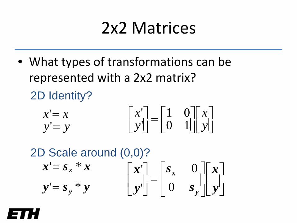
• What types of transformations can be represented with a 2x2 matrix?2D Identity?
yyxx
==''
=
yx
yx
1001
''
2D Scale around (0,0)?
ysyxsx
y
x
*'
*'
=
=
=
yx
ss
yx
y
x
00
''
2x2 Matrices
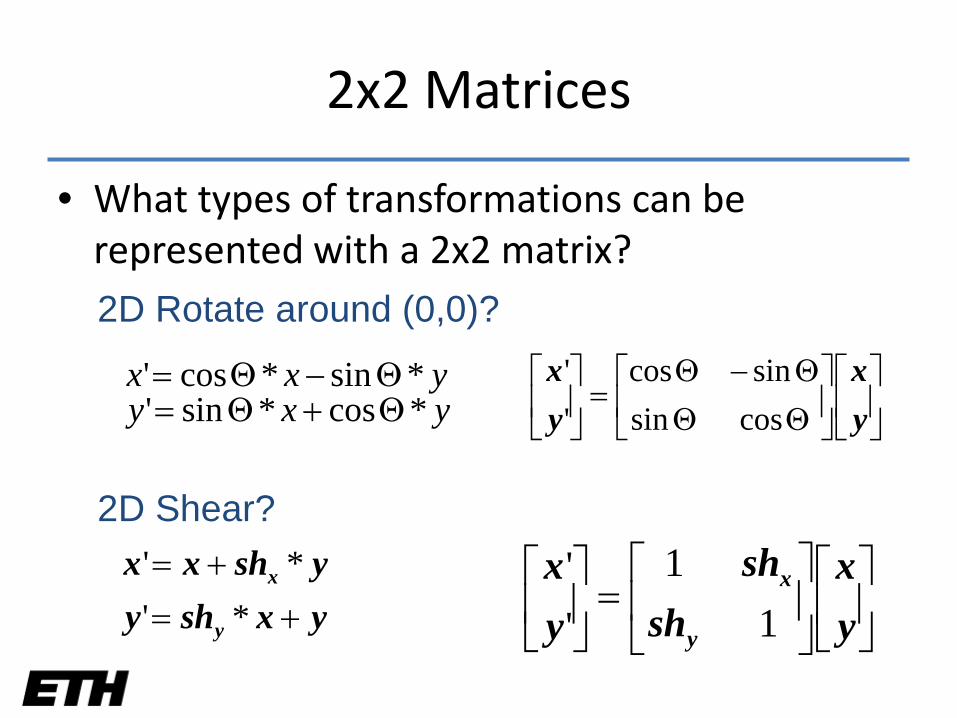
• What types of transformations can be represented with a 2x2 matrix?2D Rotate around (0,0)?
yxyyxx
*cos*sin'*sin*cos'
Θ+Θ=Θ−Θ=
ΘΘΘ−Θ
=
yx
yx
cossinsincos
''
2D Shear?
yxshyyshxx
y
x
+=+=
*'*'
=
yx
shsh
yx
y
x
11
''
2x2 Matrices
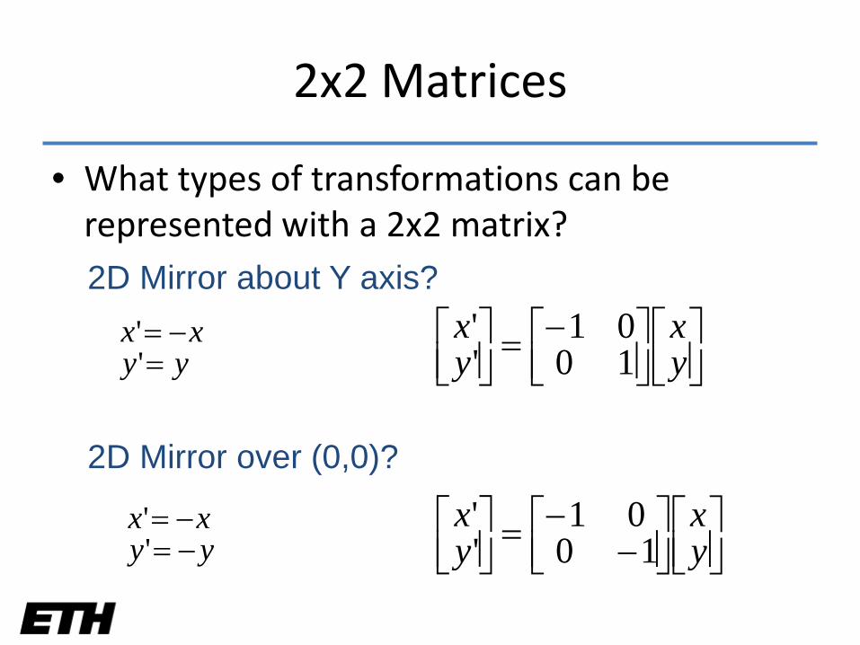
• What types of transformations can be represented with a 2x2 matrix?2D Mirror about Y axis?
yyxx
=−=
''
−=
yx
yx
1001
''
2D Mirror over (0,0)?
yyxx
−=−=
''
−−=
yx
yx
1001
''
2x2 Matrices
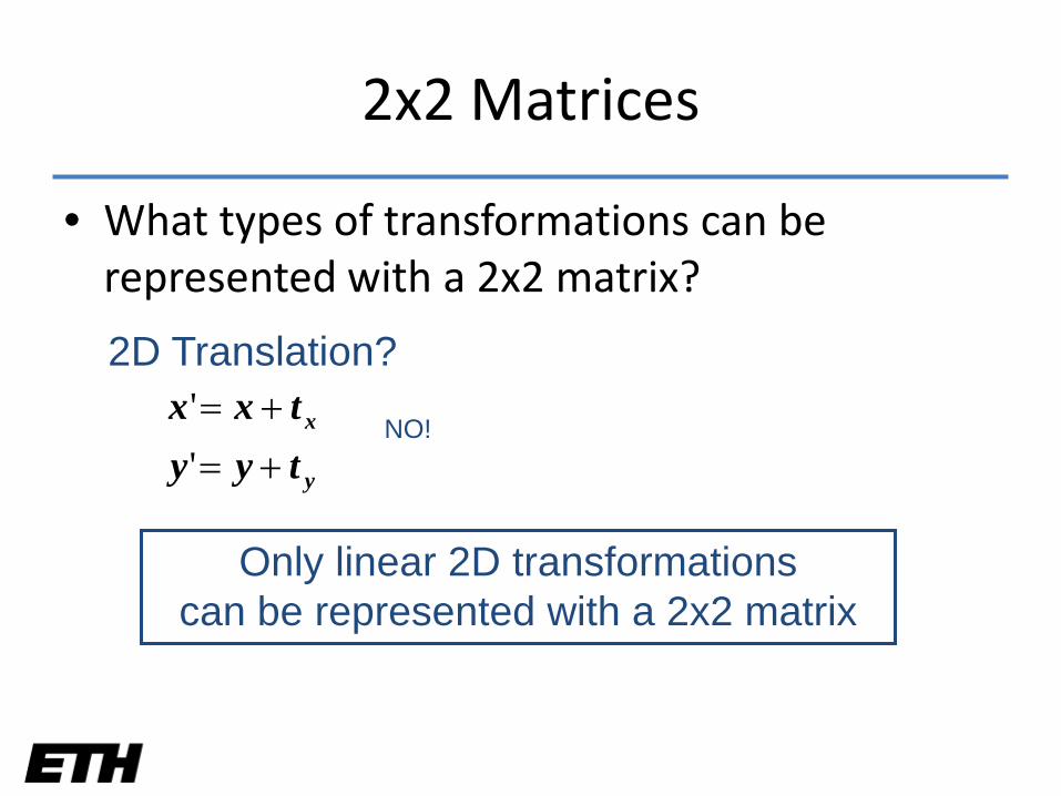
• What types of transformations can be represented with a 2x2 matrix?
2D Translation?
y
x
tyytxx
+=+=
''
Only linear 2D transformations can be represented with a 2x2 matrix
NO!
2x2 Matrices
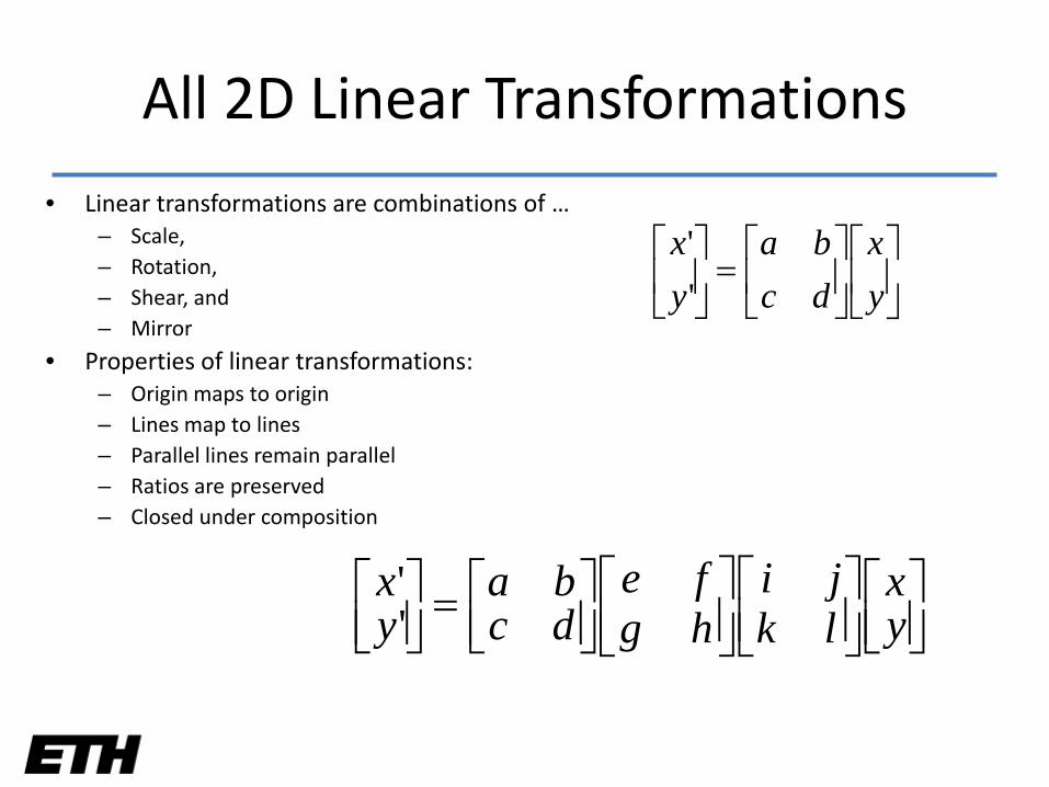
• Linear transformations are combinations of …– Scale,– Rotation,– Shear, and– Mirror
• Properties of linear transformations:– Origin maps to origin– Lines map to lines– Parallel lines remain parallel– Ratios are preserved– Closed under composition
=
yx
dcba
yx
''
=
yx
lkji
hgfe
dcba
yx''
All 2D Linear Transformations
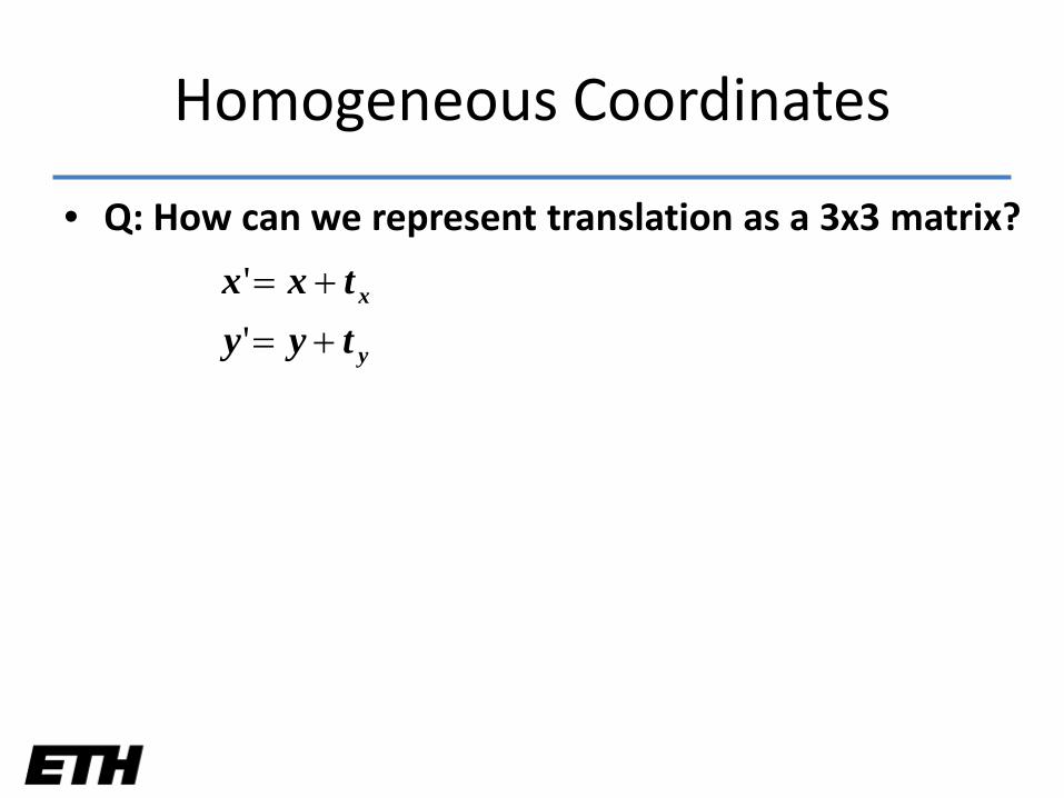
• Q: How can we represent translation as a 3x3 matrix?
y
x
tyytxx
+=+=
''
Homogeneous Coordinates
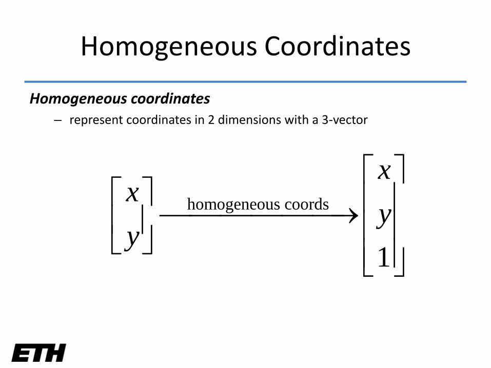
Homogeneous Coordinates
Homogeneous coordinates– represent coordinates in 2 dimensions with a 3-vector
homogeneous coords
1
xx
yy
→
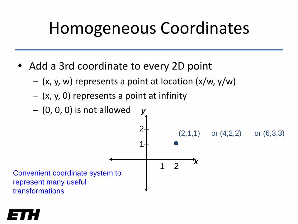
• Add a 3rd coordinate to every 2D point– (x, y, w) represents a point at location (x/w, y/w)
– (x, y, 0) represents a point at infinity
– (0, 0, 0) is not allowed
Convenient coordinate system to represent many useful transformations
1 2
1
2 (2,1,1) or (4,2,2) or (6,3,3)
x
y
Homogeneous Coordinates
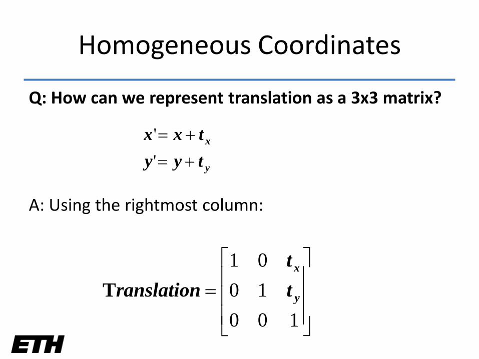
Q: How can we represent translation as a 3x3 matrix?
A: Using the rightmost column:
=100
1001
y
x
tt
ranslationT
y
x
tyytxx
+=+=
''
Homogeneous Coordinates
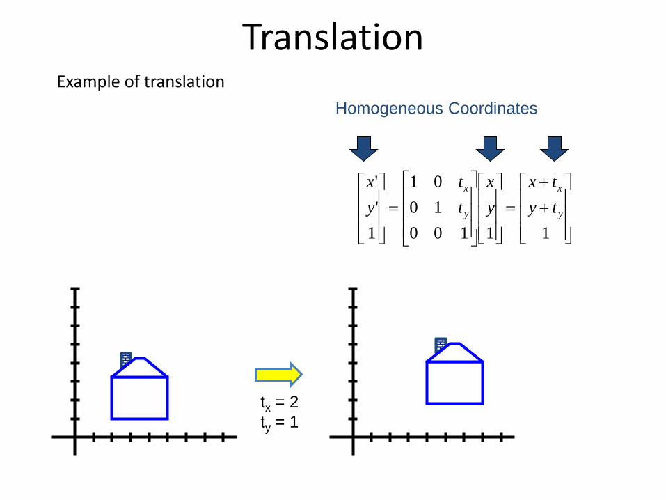
TranslationExample of translation
++
=
=
111001001
1''
y
x
y
x
tytx
yx
tt
yx
tx = 2ty = 1
Homogeneous Coordinates
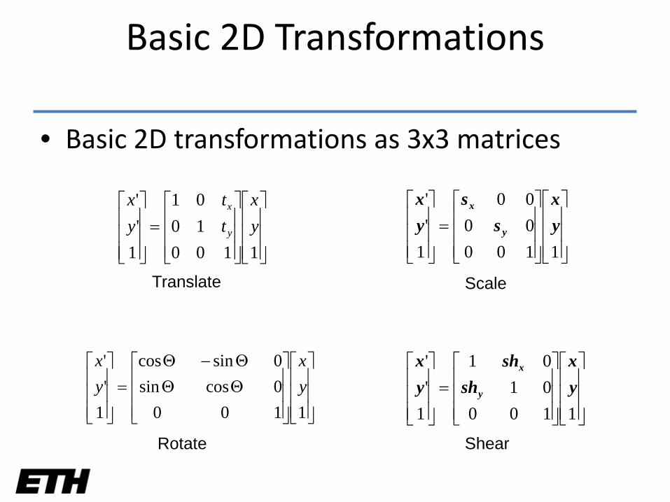
Basic 2D Transformations
• Basic 2D transformations as 3x3 matrices
ΘΘΘ−Θ
=
11000cossin0sincos
1''
yx
yx
=
11001001
1''
yx
tt
yx
y
x
=
11000101
1''
yx
shsh
yx
y
x
Translate
Rotate Shear
=
11000000
1''
yx
ss
yx
y
x
Scale
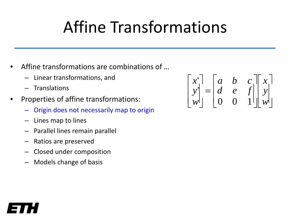
• Affine transformations are combinations of …– Linear transformations, and
– Translations
• Properties of affine transformations:– Origin does not necessarily map to origin
– Lines map to lines
– Parallel lines remain parallel
– Ratios are preserved
– Closed under composition
– Models change of basis
=
wyx
fedcba
wyx
100''
Affine Transformations
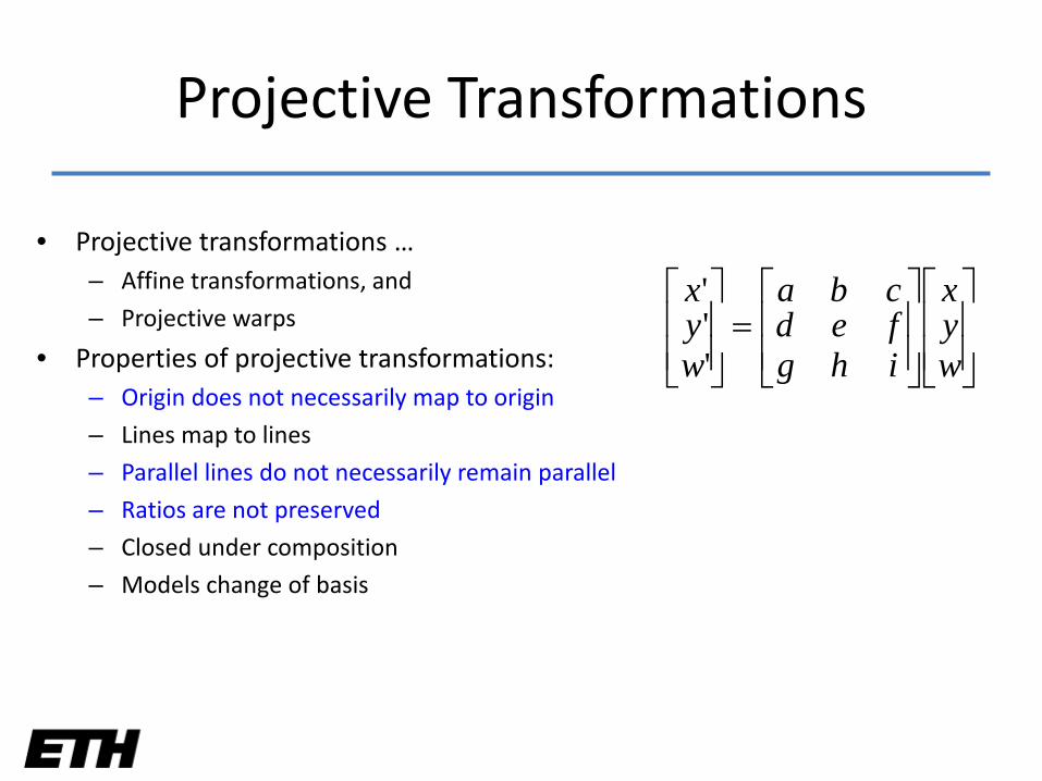
• Projective transformations …– Affine transformations, and
– Projective warps
• Properties of projective transformations:– Origin does not necessarily map to origin
– Lines map to lines
– Parallel lines do not necessarily remain parallel
– Ratios are not preserved
– Closed under composition
– Models change of basis
=
wyx
ihgfedcba
wyx
'''
Projective Transformations
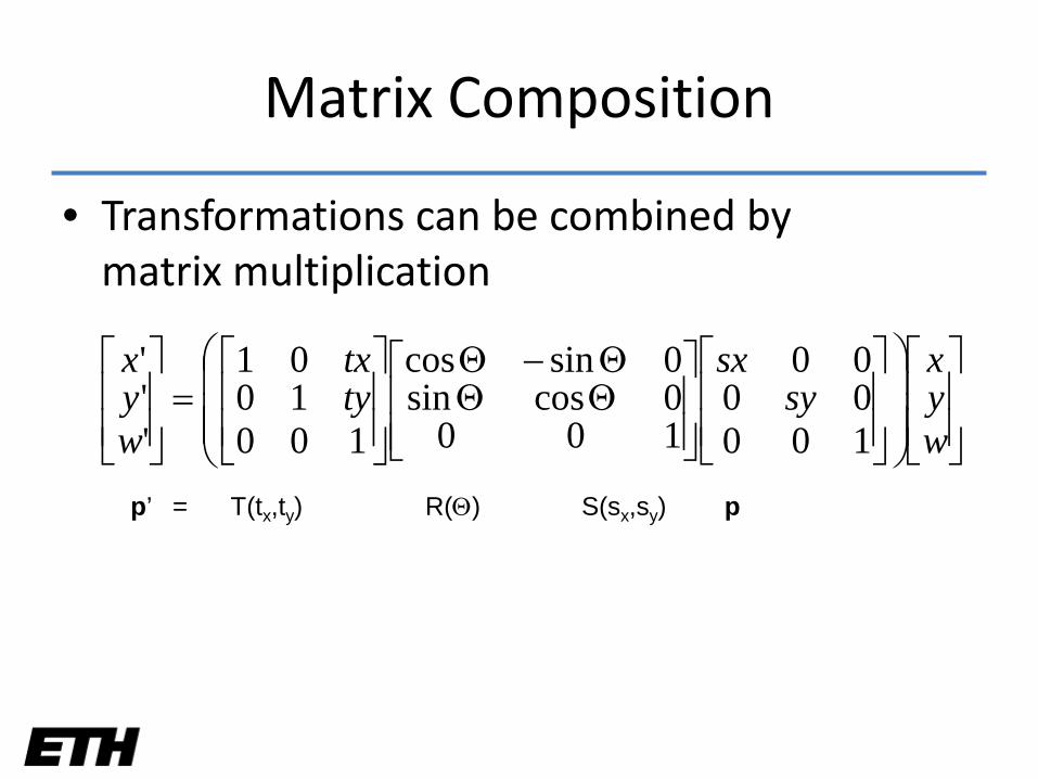
• Transformations can be combined by matrix multiplication
ΘΘΘ−Θ
=
wyx
sysx
tytx
wyx
1000000
1000cossin0sincos
1001001
'''
p’ = T(tx,ty) R(Θ) S(sx,sy) p
Matrix Composition
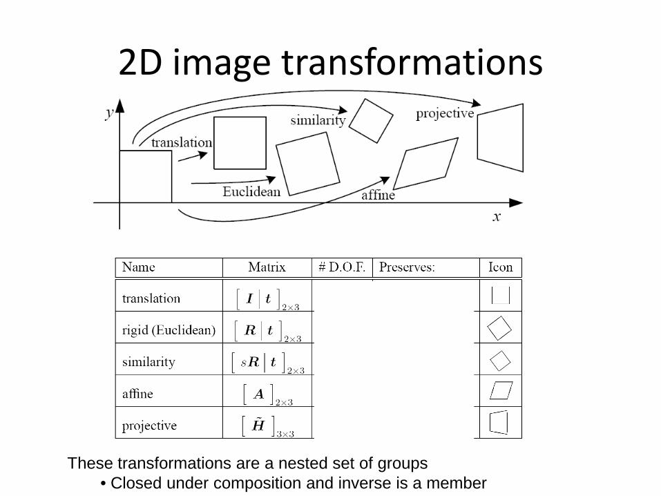
2D image transformations
These transformations are a nested set of groups• Closed under composition and inverse is a member
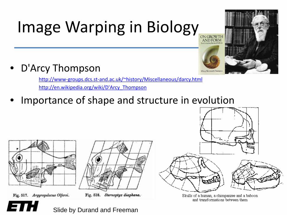
• D'Arcy Thompson http://www-groups.dcs.st-and.ac.uk/~history/Miscellaneous/darcy.html
http://en.wikipedia.org/wiki/D'Arcy_Thompson
• Importance of shape and structure in evolution
Slide by Durand and Freeman
Image Warping in Biology
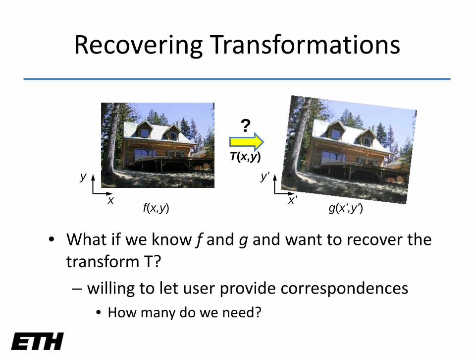
Recovering Transformations
• What if we know f and g and want to recover the transform T?
– willing to let user provide correspondences• How many do we need?
x x’
T(x,y)y y’
f(x,y) g(x’,y’)
?
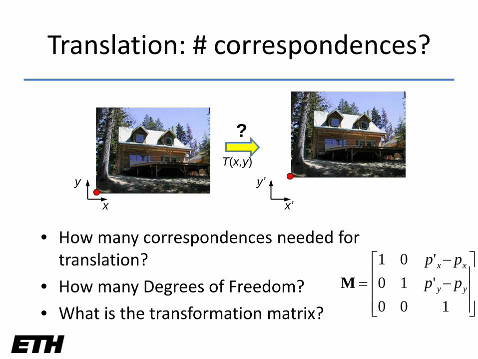
Translation: # correspondences?
• How many correspondences needed for translation?
• How many Degrees of Freedom?
• What is the transformation matrix?
x x’
T(x,y)
y y’
?
−−
=100
'10'01
yy
xx
pppp
M
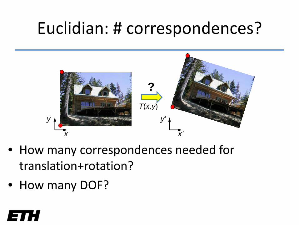
Euclidian: # correspondences?
• How many correspondences needed for translation+rotation?
• How many DOF?
x x’
T(x,y)
y y’
?
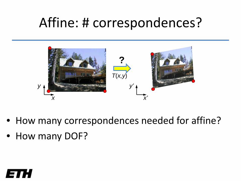
Affine: # correspondences?
• How many correspondences needed for affine?
• How many DOF?
x x’
T(x,y)
y y’
?
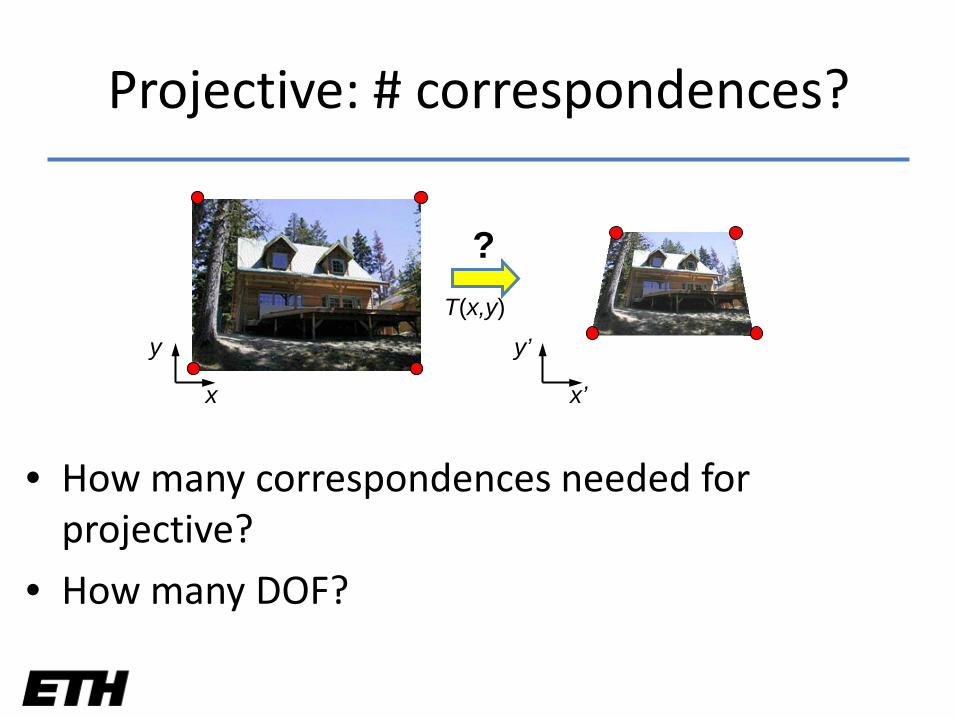
Projective: # correspondences?
• How many correspondences needed for projective?
• How many DOF?
x x’
T(x,y)
y y’
?
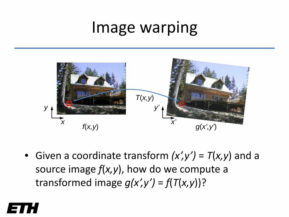
Image warping
• Given a coordinate transform (x’,y’) = T(x,y) and a source image f(x,y), how do we compute a transformed image g(x’,y’) = f(T(x,y))?
x x’
T(x,y)
f(x,y) g(x’,y’)
y y’
f(x,y) g(x’,y’)
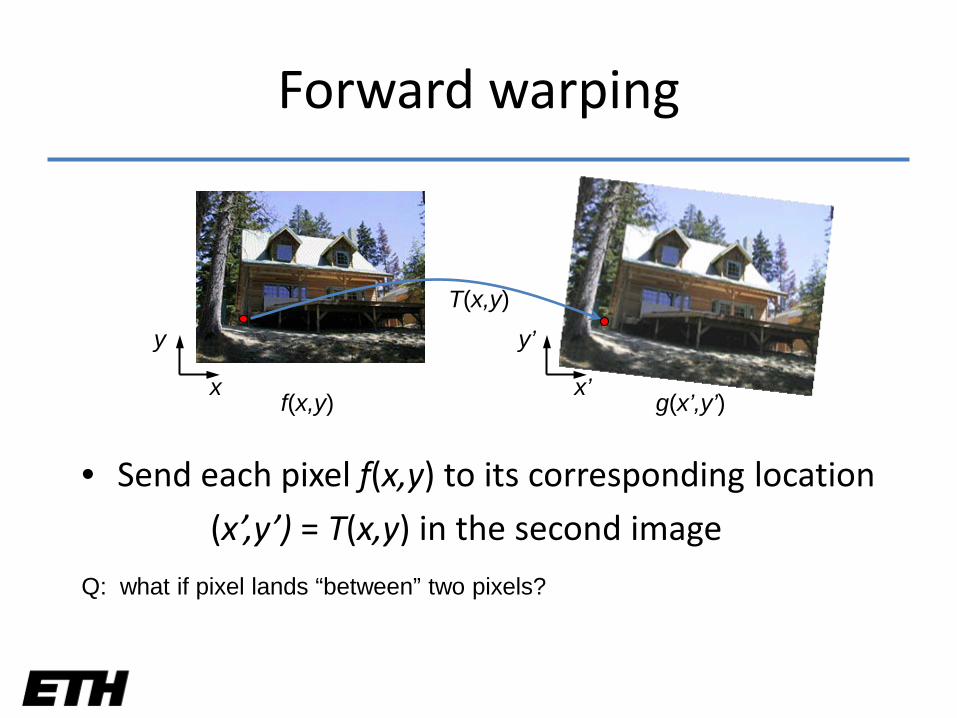
Forward warping
• Send each pixel f(x,y) to its corresponding location
(x’,y’) = T(x,y) in the second image
x x’
T(x,y)
Q: what if pixel lands “between” two pixels?
y y’
f(x,y) g(x’,y’)
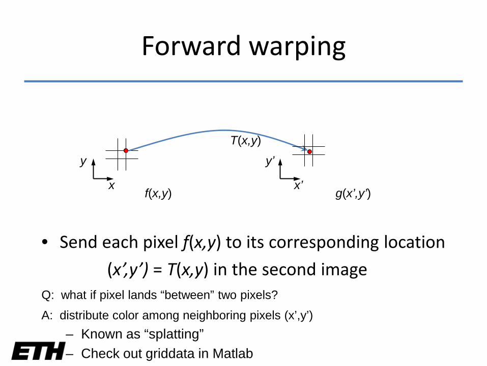
Forward warping
• Send each pixel f(x,y) to its corresponding location
(x’,y’) = T(x,y) in the second image
x x’
T(x,y)
Q: what if pixel lands “between” two pixels?
y y’
A: distribute color among neighboring pixels (x’,y’)– Known as “splatting”– Check out griddata in Matlab

f(x,y) g(x’,y’)x
y
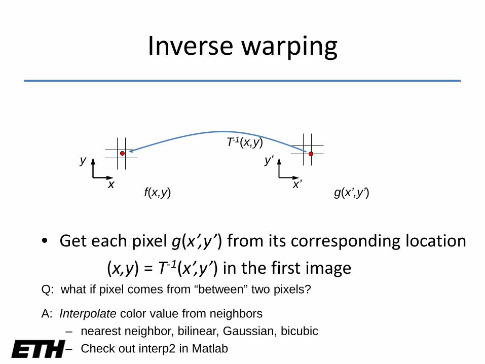
Inverse warping
• Get each pixel g(x’,y’) from its corresponding location
(x,y) = T-1(x’,y’) in the first image
x x’
Q: what if pixel comes from “between” two pixels?
y’T-1(x,y)
f(x,y) g(x’,y’)x
y
Inverse warping
• Get each pixel g(x’,y’) from its corresponding location
(x,y) = T-1(x’,y’) in the first image
x x’
T-1(x,y)
Q: what if pixel comes from “between” two pixels?
y’
A: Interpolate color value from neighbors– nearest neighbor, bilinear, Gaussian, bicubic– Check out interp2 in Matlab
Forward vs. inverse warping
Q: which is better?
A: usually inverse—eliminates holes– however, it requires an invertible warp function—not always possible...

Today’s schedule
• Last week’s recap
• Warping
• Mosaics
• Morphing
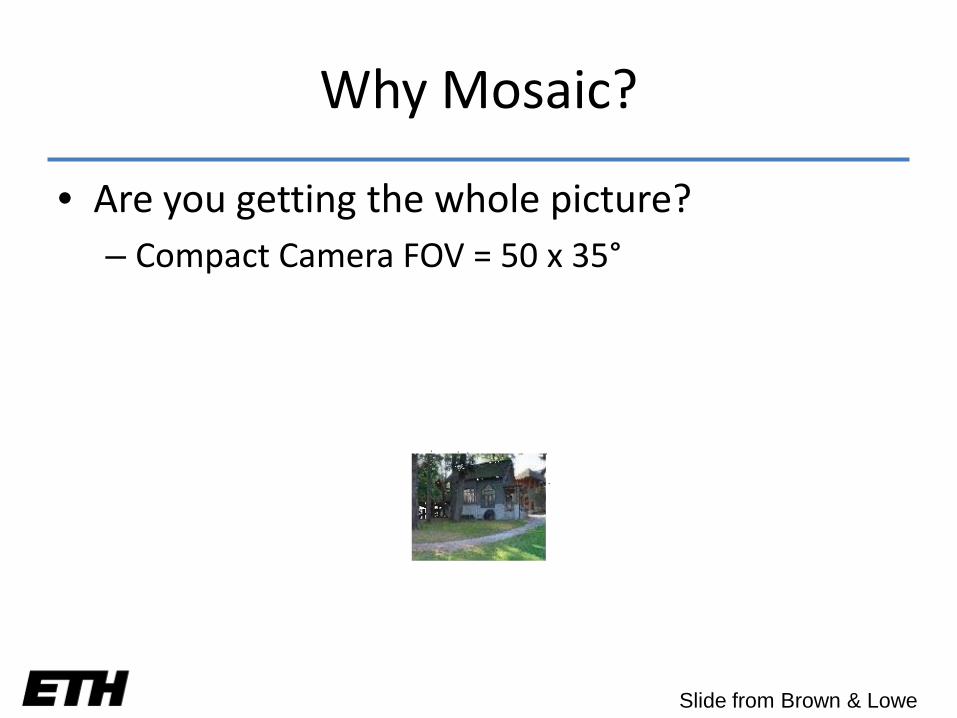
Why Mosaic?
• Are you getting the whole picture?– Compact Camera FOV = 50 x 35°
Slide from Brown & Lowe
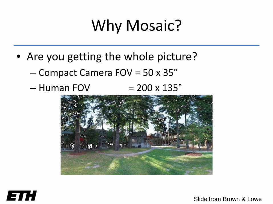
Why Mosaic?
• Are you getting the whole picture?– Compact Camera FOV = 50 x 35°
– Human FOV = 200 x 135°
Slide from Brown & Lowe
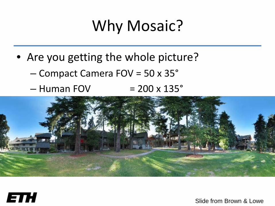
Why Mosaic?
• Are you getting the whole picture?– Compact Camera FOV = 50 x 35°
– Human FOV = 200 x 135°
– Panoramic Mosaic = 360 x 180°
Slide from Brown & Lowe
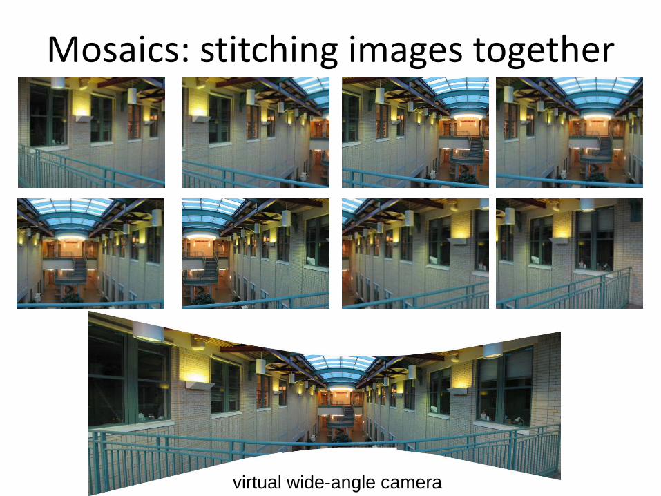
Mosaics: stitching images together
virtual wide-angle camera
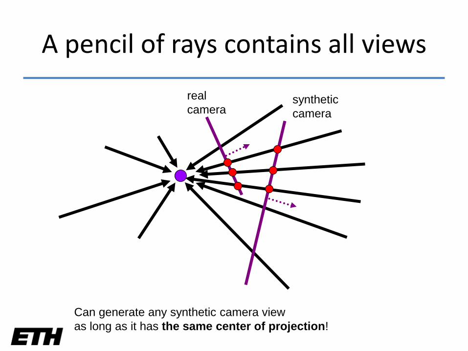
A pencil of rays contains all views
realcamera
syntheticcamera
Can generate any synthetic camera viewas long as it has the same center of projection!
How to do it?
• Basic Procedure– Take a sequence of images from the same position
• Rotate the camera about its optical center
– Compute transformation between second image and first
– Transform the second image to overlap with the first
– Blend the two together to create a mosaic
– If there are more images, repeat
• …but wait, why should this work at all?– What about the 3D geometry of the scene?
– Why aren’t we using it?
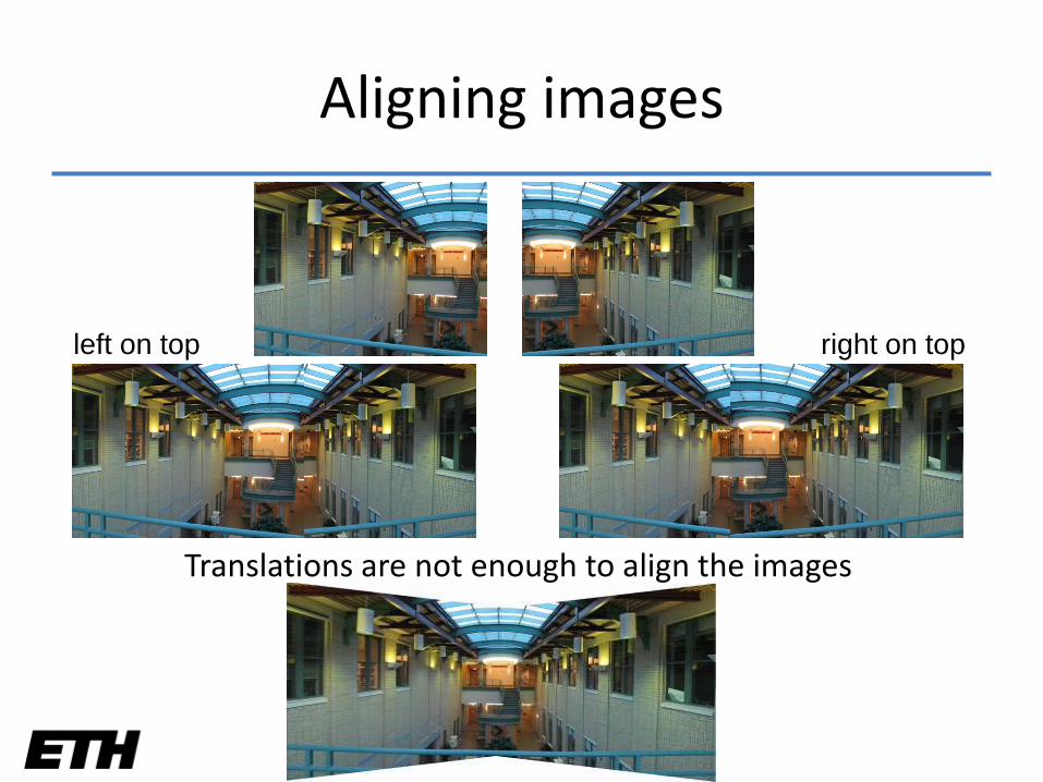
Aligning images
Translations are not enough to align the images
left on top right on top
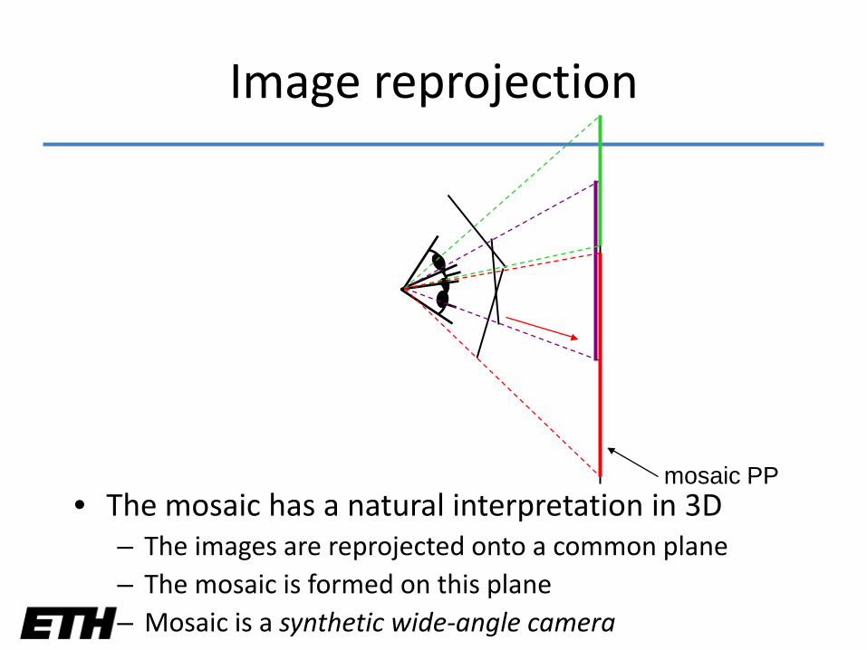
mosaic PP
Image reprojection
• The mosaic has a natural interpretation in 3D– The images are reprojected onto a common plane– The mosaic is formed on this plane– Mosaic is a synthetic wide-angle camera
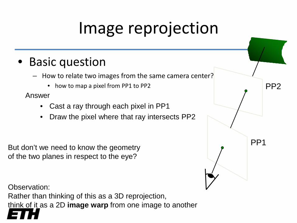
Image reprojection
• Basic question– How to relate two images from the same camera center?
• how to map a pixel from PP1 to PP2 PP2
PP1
Answer• Cast a ray through each pixel in PP1• Draw the pixel where that ray intersects PP2
But don’t we need to know the geometryof the two planes in respect to the eye?
Observation:Rather than thinking of this as a 3D reprojection, think of it as a 2D image warp from one image to another
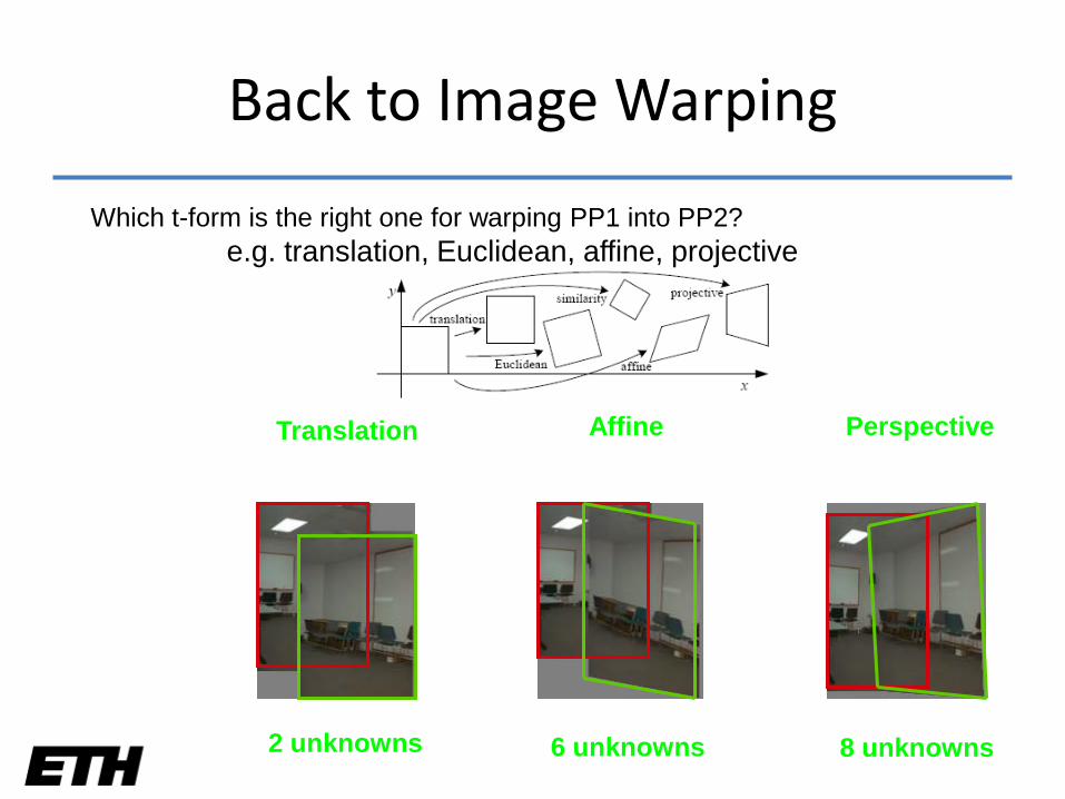
Back to Image Warping
Translation
2 unknowns
Affine
6 unknowns
Perspective
8 unknowns
Which t-form is the right one for warping PP1 into PP2?e.g. translation, Euclidean, affine, projective
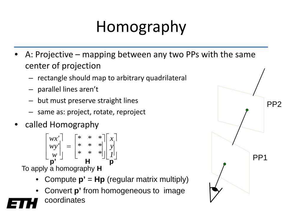
Homography
• A: Projective – mapping between any two PPs with the same center of projection– rectangle should map to arbitrary quadrilateral
– parallel lines aren’t
– but must preserve straight lines
– same as: project, rotate, reproject
• called Homography
PP2
PP1
=
1yx
*********
wwy'wx'
H pp’To apply a homography H
• Compute p’ = Hp (regular matrix multiply)• Convert p’ from homogeneous to image
coordinates
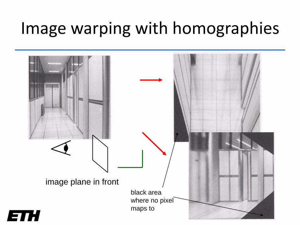
Image warping with homographies
image plane in front image plane belowblack areawhere no pixelmaps to
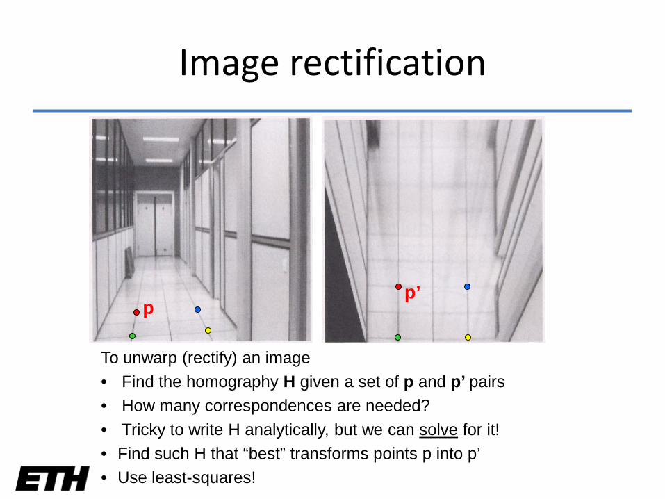
Image rectification
To unwarp (rectify) an image• Find the homography H given a set of p and p’ pairs• How many correspondences are needed?• Tricky to write H analytically, but we can solve for it!• Find such H that “best” transforms points p into p’ • Use least-squares!
pp’
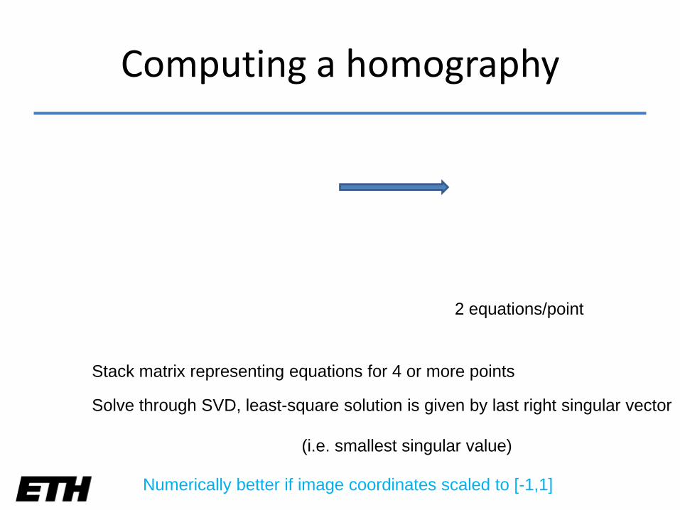
Computing a homography
Stack matrix representing equations for 4 or more points
Solve through SVD, least-square solution is given by last right singular vector
2 equations/point
Numerically better if image coordinates scaled to [-1,1]
(i.e. smallest singular value)
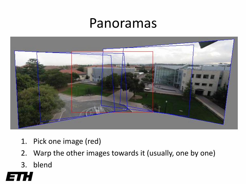
Panoramas
1. Pick one image (red)
2. Warp the other images towards it (usually, one by one)
3. blend
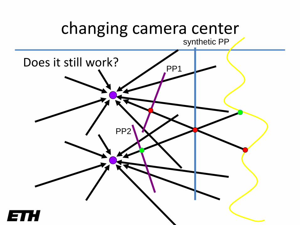
changing camera center
Does it still work?
synthetic PP
PP1
PP2
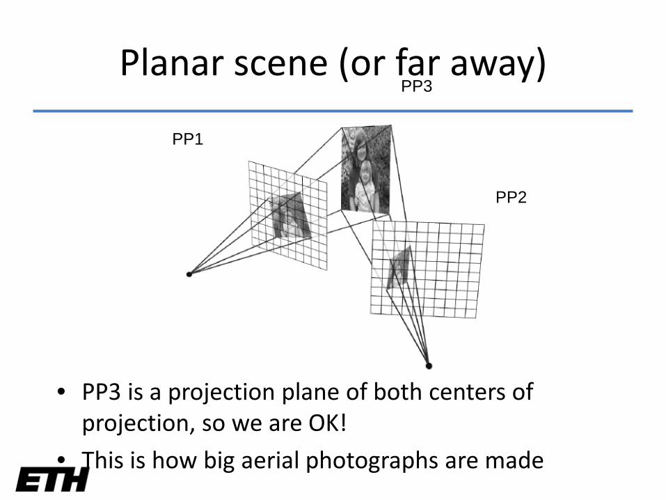
Planar scene (or far away)
• PP3 is a projection plane of both centers of projection, so we are OK!
• This is how big aerial photographs are made
PP1
PP3
PP2
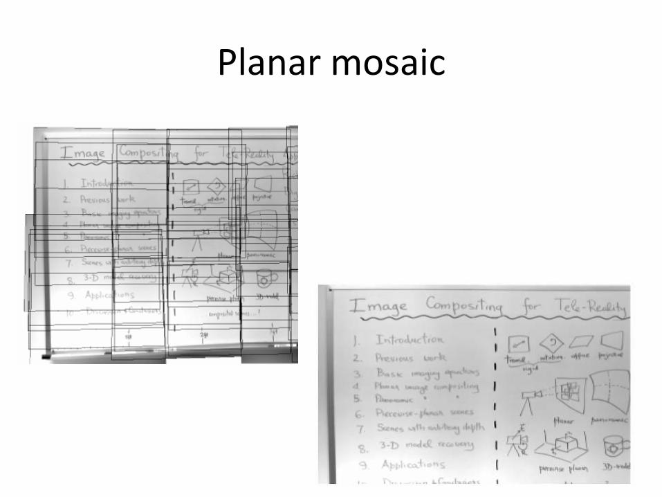
Planar mosaic

Today’s schedule
• Last week’s recap
• Warping
• Mosaics
• Morphing
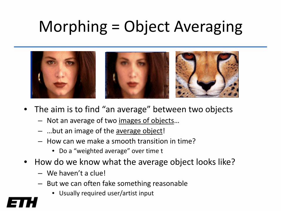
Morphing = Object Averaging
• The aim is to find “an average” between two objects– Not an average of two images of objects…– …but an image of the average object!– How can we make a smooth transition in time?
• Do a “weighted average” over time t
• How do we know what the average object looks like?– We haven’t a clue!– But we can often fake something reasonable
• Usually required user/artist input
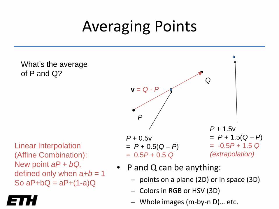
P
Qv = Q - P
P + 0.5v= P + 0.5(Q – P)= 0.5P + 0.5 Q
P + 1.5v= P + 1.5(Q – P)= -0.5P + 1.5 Q(extrapolation)
Linear Interpolation(Affine Combination):New point aP + bQ,defined only when a+b = 1So aP+bQ = aP+(1-a)Q
Averaging Points
• P and Q can be anything:– points on a plane (2D) or in space (3D)
– Colors in RGB or HSV (3D)
– Whole images (m-by-n D)… etc.
What’s the averageof P and Q?
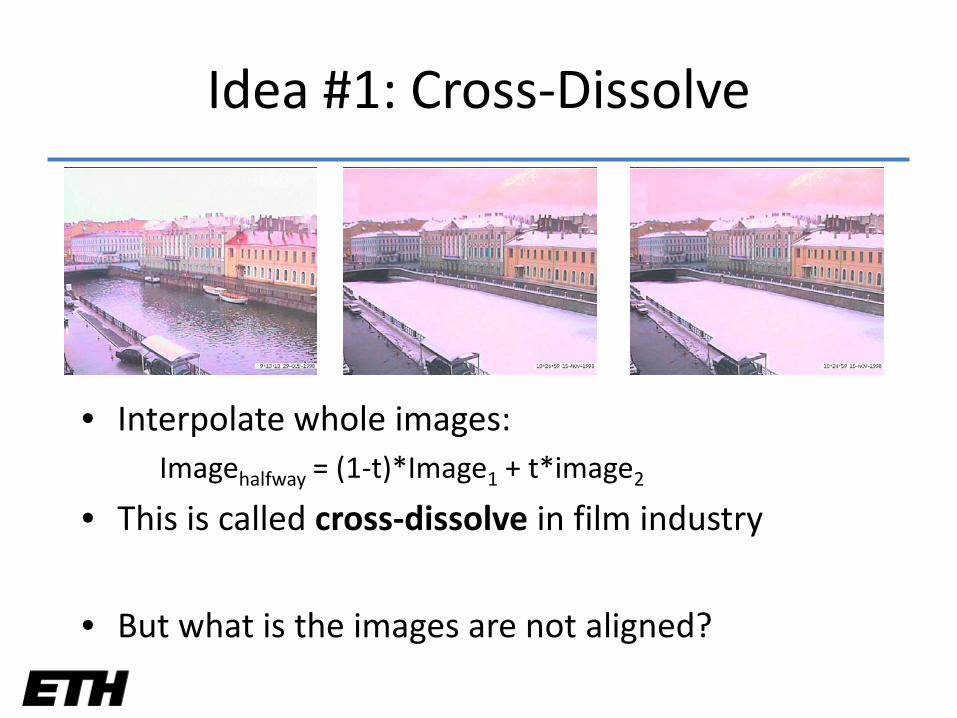
Idea #1: Cross-Dissolve
• Interpolate whole images:Imagehalfway = (1-t)*Image1 + t*image2
• This is called cross-dissolve in film industry
• But what is the images are not aligned?
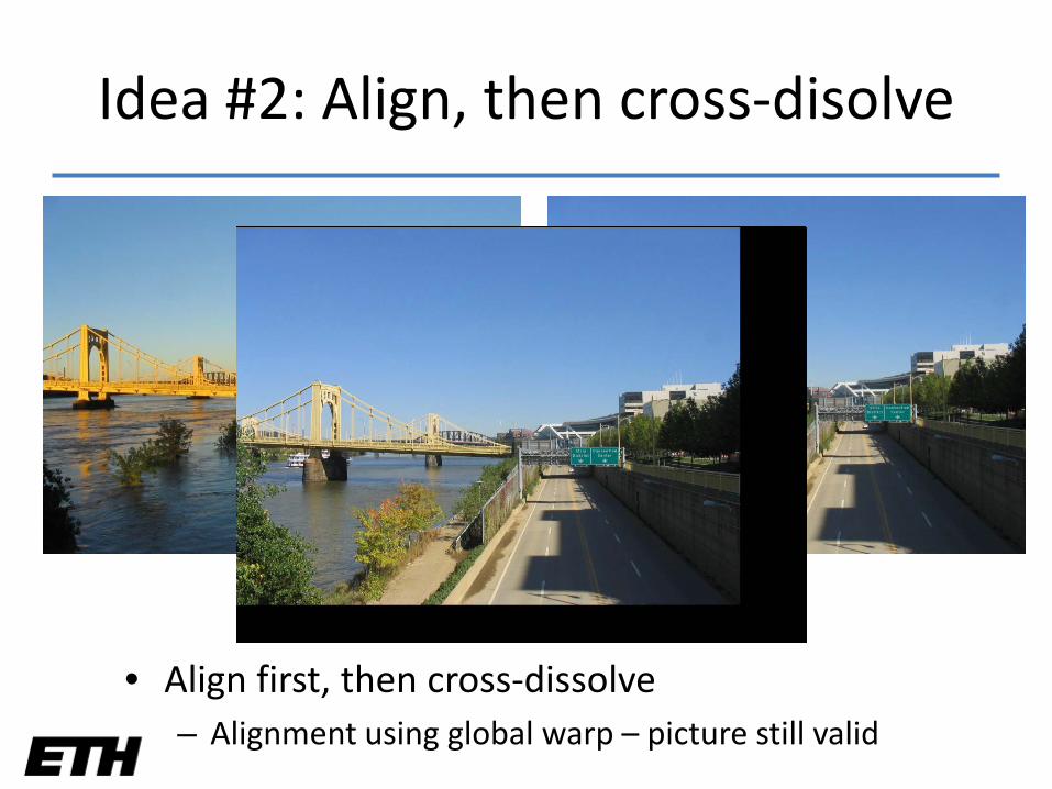
Idea #2: Align, then cross-disolve
• Align first, then cross-dissolve– Alignment using global warp – picture still valid
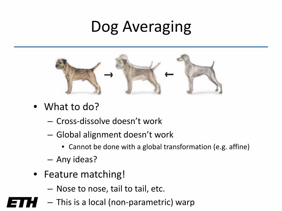
Dog Averaging
• What to do?– Cross-dissolve doesn’t work
– Global alignment doesn’t work• Cannot be done with a global transformation (e.g. affine)
– Any ideas?
• Feature matching!– Nose to nose, tail to tail, etc.
– This is a local (non-parametric) warp
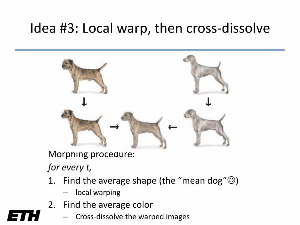
Morphing procedure: for every t,1. Find the average shape (the “mean dog”)
– local warping
2. Find the average color– Cross-dissolve the warped images
Idea #3: Local warp, then cross-dissolve
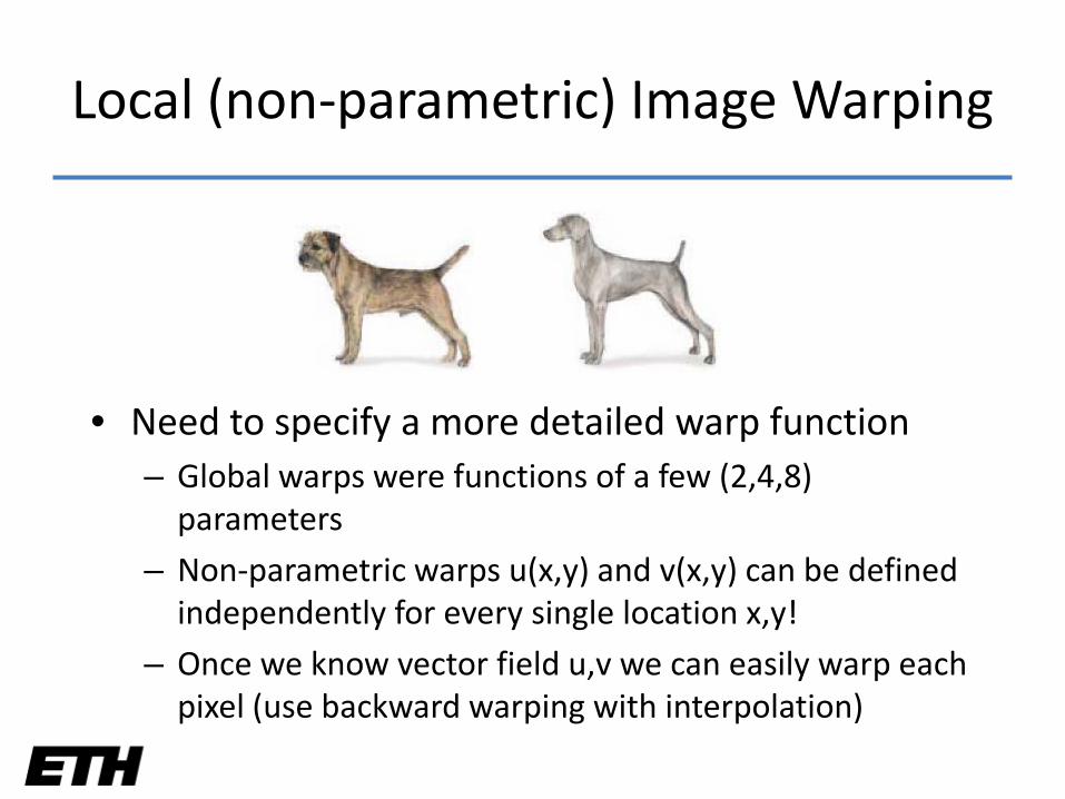
Local (non-parametric) Image Warping
• Need to specify a more detailed warp function– Global warps were functions of a few (2,4,8)
parameters
– Non-parametric warps u(x,y) and v(x,y) can be defined independently for every single location x,y!
– Once we know vector field u,v we can easily warp each pixel (use backward warping with interpolation)
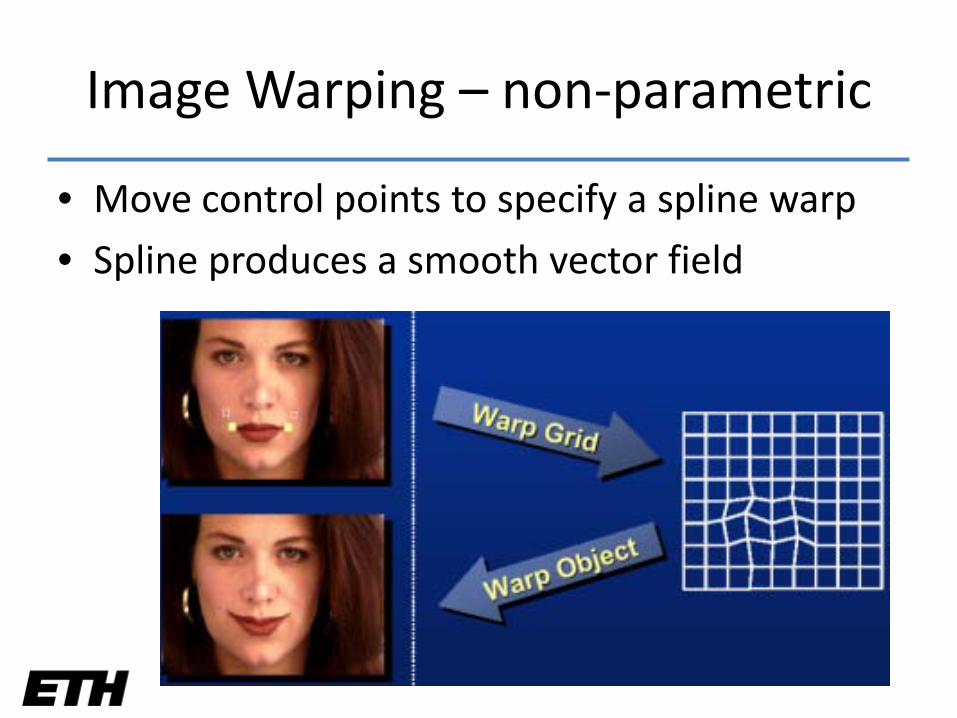
Image Warping – non-parametric
• Move control points to specify a spline warp
• Spline produces a smooth vector field
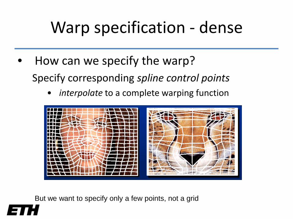
Warp specification - dense
• How can we specify the warp?Specify corresponding spline control points
• interpolate to a complete warping function
But we want to specify only a few points, not a grid
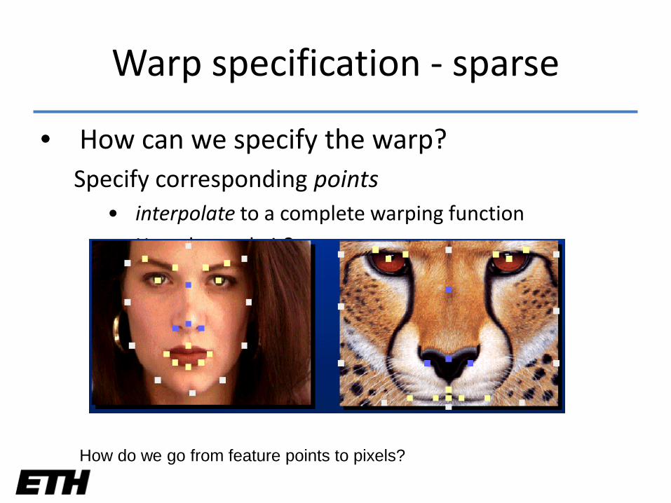
Warp specification - sparse
• How can we specify the warp?Specify corresponding points
• interpolate to a complete warping function
• How do we do it?
How do we go from feature points to pixels?
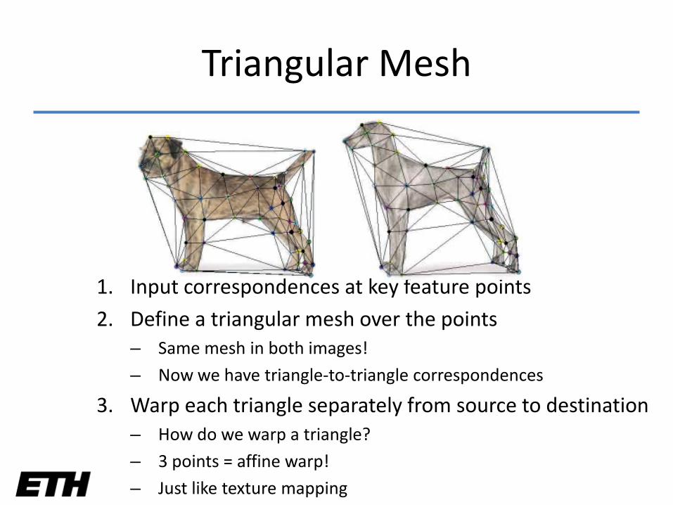
Triangular Mesh
1. Input correspondences at key feature points
2. Define a triangular mesh over the points– Same mesh in both images!
– Now we have triangle-to-triangle correspondences
3. Warp each triangle separately from source to destination– How do we warp a triangle?
– 3 points = affine warp!
– Just like texture mapping
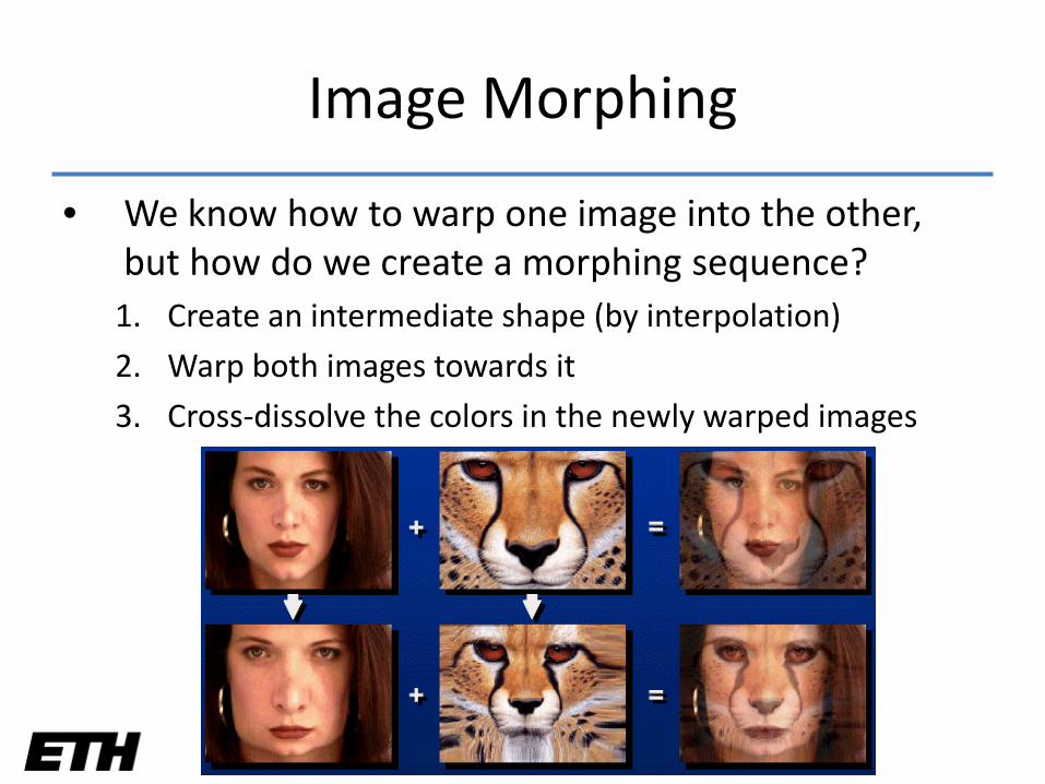
Image Morphing
• We know how to warp one image into the other, but how do we create a morphing sequence?
1. Create an intermediate shape (by interpolation)
2. Warp both images towards it
3. Cross-dissolve the colors in the newly warped images
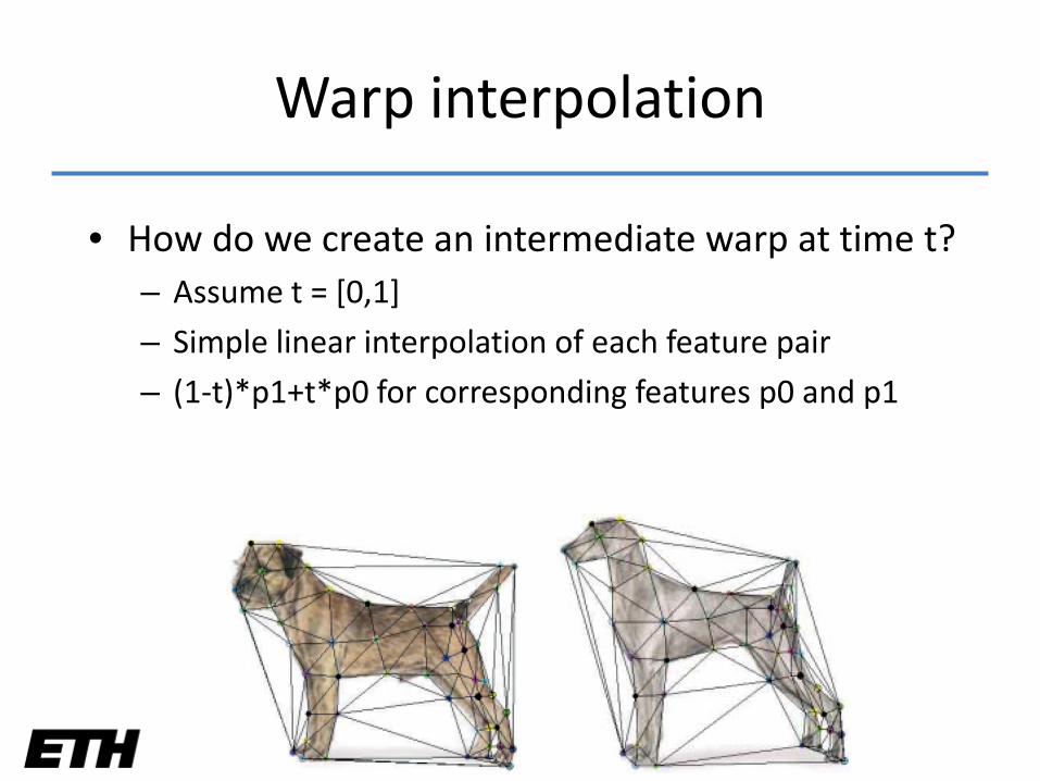
Warp interpolation
• How do we create an intermediate warp at time t?– Assume t = [0,1]
– Simple linear interpolation of each feature pair
– (1-t)*p1+t*p0 for corresponding features p0 and p1
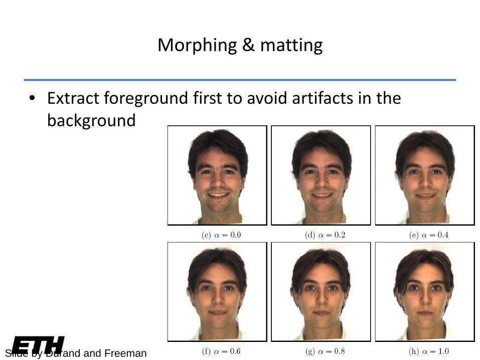
Morphing & matting
• Extract foreground first to avoid artifacts in the background
Slide by Durand and Freeman
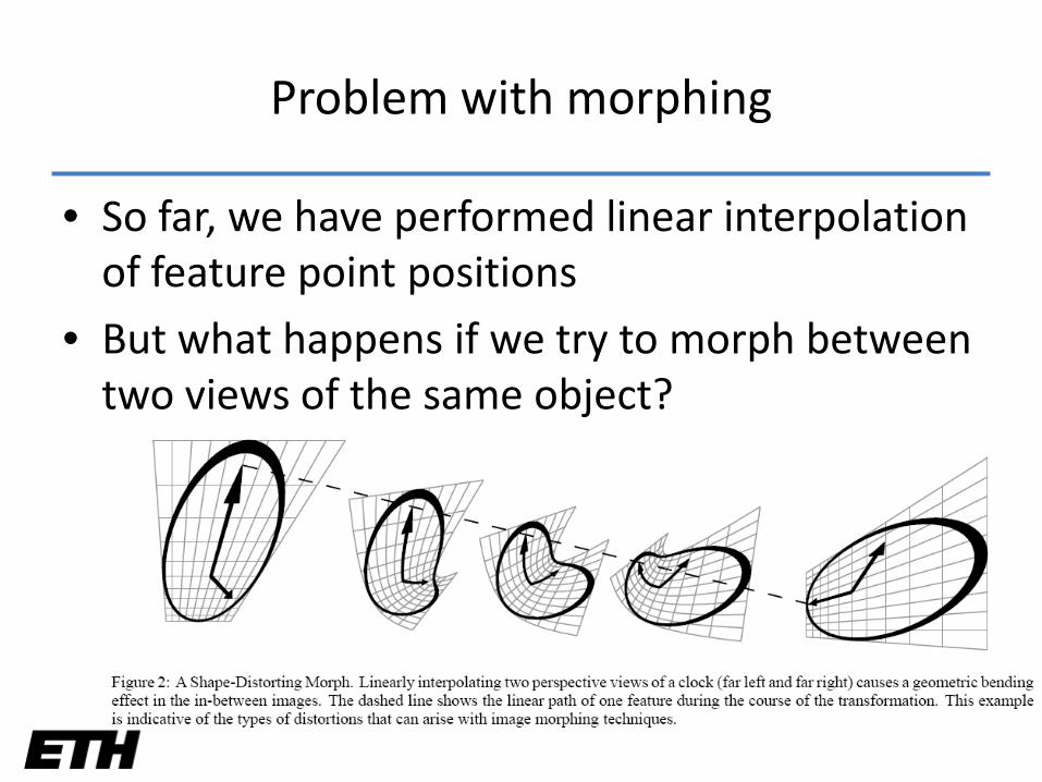
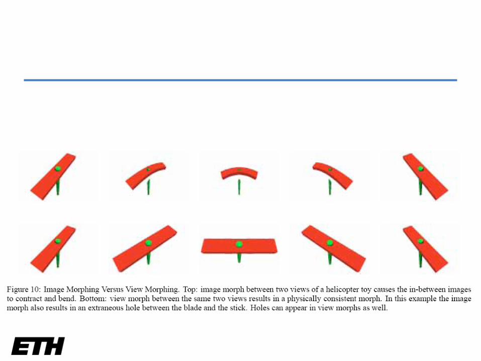
Problem with morphing
• So far, we have performed linear interpolation of feature point positions
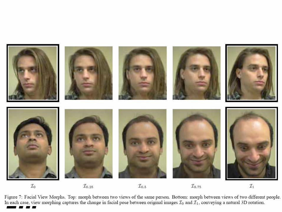
• But what happens if we try to morph between two views of the same object?
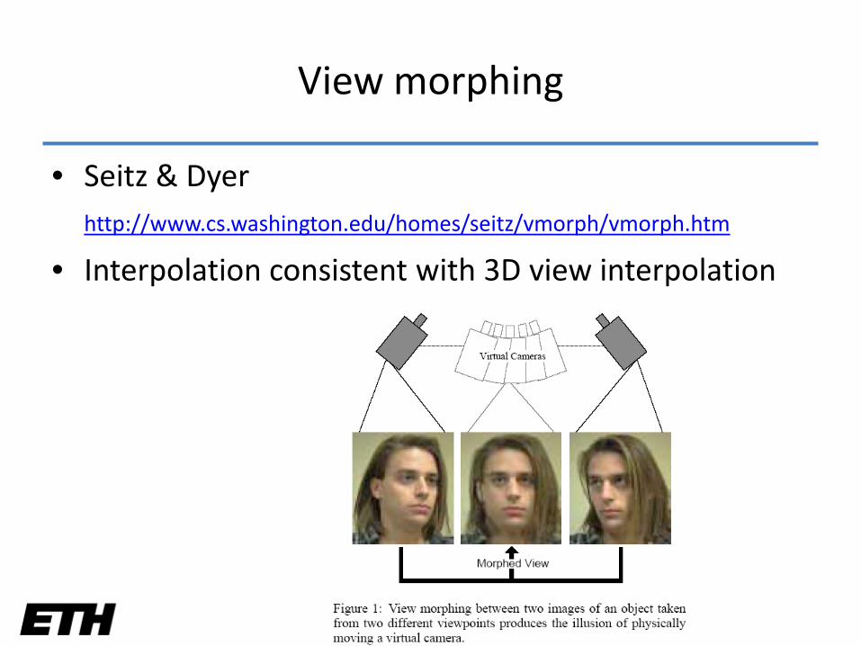
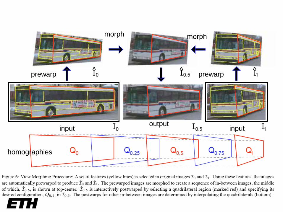
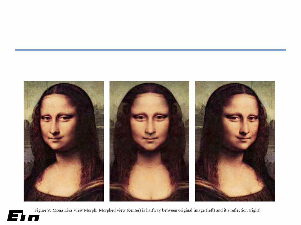
View morphing
• Seitz & Dyerhttp://www.cs.washington.edu/homes/seitz/vmorph/vmorph.htm
• Interpolation consistent with 3D view interpolation
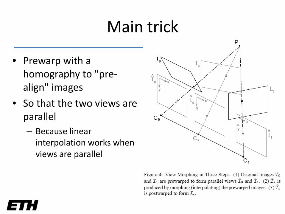
Main trick
• Prewarp with a homography to "pre-align" images
• So that the two views are parallel– Because linear
interpolation works when views are parallel
prewarp prewarp
morph morph
homographies
input inputoutput
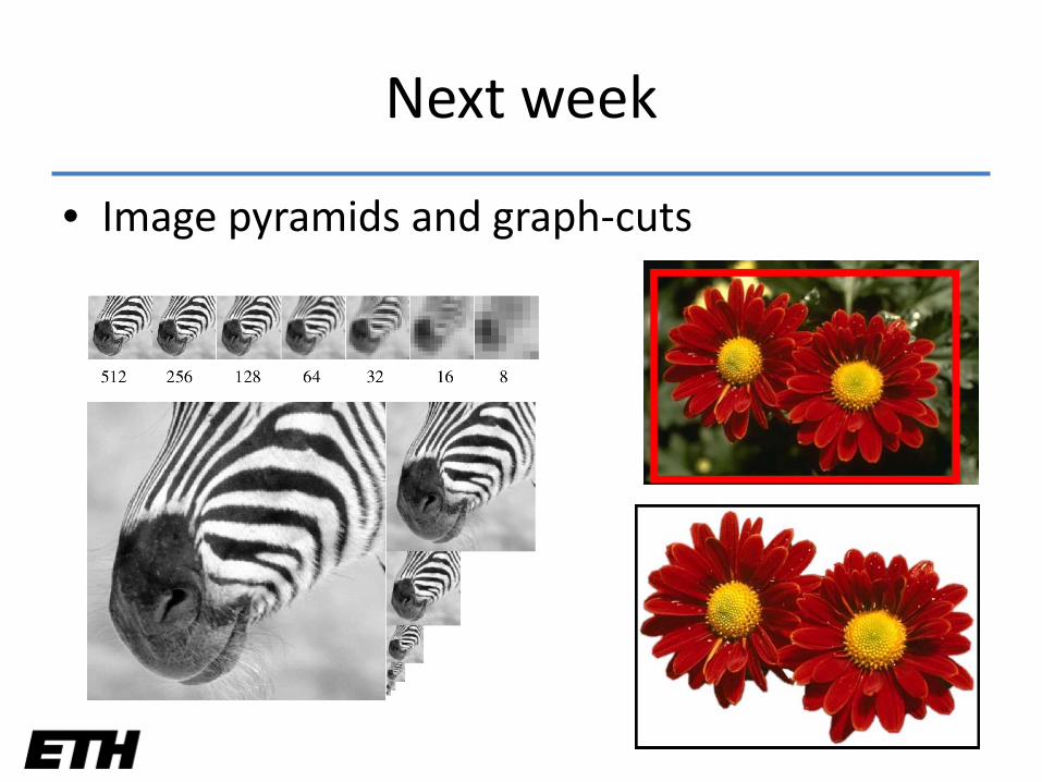
Next week
• Image pyramids and graph-cuts