computational system for real-time distributed control - dario
TRANSCRIPT
Computational System for Real-Time DistributedControl
Jose Manuel de Sousa de Matos Rufino(Mestre)
Dissertacao para obtencao do Grau de Doutor em
Engenharia Electrotecnica e de Computadores
Orientador: Doutor Paulo Jorge Esteves Verıssimo
Co-Orientador: Doutor Guilherme Diniz Moreno da Silva Arroz
Presidente: Reitor da Universidade Tecnica de Lisboa
Vogais: Doutor Alan Burns
Doutor Paulo Jorge Esteves Verıssimo
Doutor Guilherme Diniz Moreno da Silva Arroz
Doutor Antonio Manuel dos Santos Pascoal
Doutor Rui Manuel Rodrigues Rocha
Doutor Francisco Manuel Madureira e Castro Vasques de Carvalho
Julho 2002


Computational System for Real-Time Distributed Control
Jose Manuel de Sousa de Matos Rufino
Tese submetida para provas
de doutoramento em
Engenharia Electrotecnica e de Computadores
Departamento de Engenharia Electrotecnica e de Computadores
Instituto Superior Tecnico
Lisboa
Julho 2002


Este trabalho foi parcialmente financiado por:
FCT - Fundacao para a Ciencia e a Tecnologia
(atraves do Projecto PRAXIS/P/EEI/14187/1998: DEAR-COTS)
FEDER e fundos nacionais
(ao abrigo do Programa POSI)


Tese realizada sob a orientacao do
Prof. Doutor Paulo Jorge Esteves Verıssimo
Professor Catedratico do Departamento de Informatica da Faculdade de Ciencias da
Universidade de Lisboa
e co-orientacao do
Prof. Doutor Guilherme Dinis Moreno da Silva Arroz
Professor Associado do Departamento de Engenharia Electrotecnica e de
Computadores do Instituto Superior Tecnico da Universidade Tecnica de Lisboa


Resumo
As redes industriais normalizadas representam hoje em dia uma solucao atractiva
na concepcao de sistemas de controlo distribuıdo. Contudo, a concretizacao eficiente
de mecanismos de tolerancia a faltas e tempo-real nesta famılia de redes, nao e uma
simples tarefa de engenharia. Antes pelo contrario, envolve a resolucao de um conjunto
complexo e abrangente de problemas conceptuais, que abordamos no contexto da rede
CAN (Controller Area Network).
Um problema fundamental refere-se a disponibilidade de servicos de comunicacao
fiavel. O equıvoco de que a rede CAN garante a difusao fiavel de mensagens e desfeito.
Reflectindo sobre a fiabilidade das comunicacoes CAN e suas fragilidades, discute-se
uma famılia de protocolos que garante: difusao atomica e fiavel de mensagens; deteccao
de falhas e filiacao de estacoes; sincronizacao de relogios.
Contradizendo a conviccao generalizada que uma infra-estrutura de meio fısico
redundante seria de difıcil concretizacao em CAN, discute-se um mecanismo inovador
e extremamente simples que torna aquela ideia viavel, usando apenas componentes
convencionais. A robustez da rede CAN face a particoes permanentes e acautelada.
Finalmente, aborda-se um tema muito menosprezado na analise das propriedades
temporais da rede CAN: o efeito de particoes temporarias (inacessibilidade). Em
concreto, discute-se como acautelar o comportamento em tempo-real da rede CAN na
presenca de erros.


Abstract
Standard fieldbuses are nowadays a cost-effective solution for distributed control
systems. However, the efficient implementation of fault-tolerance and real-time mech-
anisms on fieldbus environments is far from being a plain engineering task. Rather, it
poses a comprehensive set of non-trivial problems whose solution requires a systemic
approach, taken here in the context of CAN, the Controller Area Network.
One key point is that fault-tolerant distributed systems may take advantage from the
availability of reliable communications. In this regard, we dismiss the misconception
that CAN native mechanisms guarantee reliable message broadcast. Then, reasoning
about the reliability of CAN communications and their weaknesses, we discuss a suite
of low-level protocols providing: reliable and atomic broadcast; node failure detection
and site membership; clock synchronization.
Refuting a common belief that bus media redundancy is too complex to be im-
plemented in the CAN infrastructure, we present an innovative and extremely simple
mechanism that makes such an approach feasible, using off-the-shelf components. This
secures resilience against permanent partitioning of the CAN infrastructure.
In addition, we discuss a problem often disregarded in many analysis of CAN
timing properties: temporary partitions (inaccessibility). We explain how to secure
CAN real-time operation in the presence of temporary network errors.


Palavras Chave
Sistemas distribuıdos
Tolerancia a faltas e tempo-real
Rede CAN (Controller Area Network)
Protocolos de difusao fiavel
Replicacao do meio fısico
Particoes da rede (inacessibilidade)
Keywords
Distributed systems
Fault-tolerance and real-time
CAN fieldbus
Reliable broadcast protocols
Media replication
Network partitioning (inaccessibility)

Agradecimentos
Aos meus orientadores, Prof. Paulo Verıssimo (orientador cientıfico) e Prof.
Guilherme Arroz (co-orientador), a quem desejo expressar o meu reconhecimento pelo
empenho que colocaram na orientacao deste trabalho. As suas crıticas, sugestoes,
incentivo e apoio constantes contribuiram de forma decisiva para a elaboracao da
presente dissertacao.
Ao Prof. Carlos Almeida (IST) pelas diversas e sempre frutuosas horas de dis-
cussao. Ao Prof. Luıs Rodrigues (FCUL) pela sua colaboracao em alguns dos trabalhos
cientıficos que estiveram na base desta dissertacao.
Aos colegas da Seccao de Sistemas Digitais e Computadores e do Centro de Sistemas
Telematicos e Computacionais (CSTC) pela excelente camaradagem, apoio e elevado
profissionalismo.
Ao Instituto Superior Tecnico e ao Centro de Sistemas Telematicos e Computa-
cionais, pela disponibilizacao dos meios tecnicos e de enquadramento cientıfico essen-
ciais para a realizacao deste trabalho.
Lisboa, Julho 2002
Jose Manuel de Sousa de Matos Rufino


Aos meus pais.


Contents
1 Introduction 1
1.1 Motivation ��������������������������������������������������������������������� 3
1.2 Approach to the Problem ����������������������������������������������������� 6
1.3 Research Contributions ������������������������������������������������������� 8
1.4 Document Organization ������������������������������������������������������� 9
2 State of the Art 11
2.1 Reliable Communications ����������������������������������������������������� 13
2.2 Dependability and Real-Time in LAN-based Systems ��������������������� 17
2.2.1 Network Availability ������������������������������������������������� 18
2.2.2 Enforcing a Bounded Transmission Time ��������������������������� 19
2.2.3 Handling Omission Failures ����������������������������������������� 22
2.2.4 Controlling Partitions: Inaccessibility ������������������������������� 24
2.3 Fieldbus Technologies ��������������������������������������������������������� 25
2.4 The TTP Architecture ��������������������������������������������������������� 37
2.5 TTP versus CAN ��������������������������������������������������������������� 40
2.6 Design of Dependable CAN-based Systems ��������������������������������� 43
i

3 Controller Area Network 45
3.1 CAN Physical Layer ����������������������������������������������������������� 47
3.2 CAN Data-Link Layer ��������������������������������������������������������� 52
3.3 Error Handling and Fault Confinement ������������������������������������� 61
3.4 Summary ����������������������������������������������������������������������� 66
4 Designing Dependable CAN-based Systems 69
4.1 Dependability of CAN ��������������������������������������������������������� 71
4.1.1 Reliability of CAN Communications ��������������������������������� 71
4.1.2 CAN Physical Level Fault-Tolerance ��������������������������������� 76
4.1.3 Reliable Hard Real-Time Operation of CAN ����������������������� 77
4.2 System Model ����������������������������������������������������������������� 79
4.2.1 Assumptions ����������������������������������������������������������� 79
4.2.2 CAN physical-level properties ��������������������������������������� 81
4.2.3 CAN MAC-level properties ������������������������������������������� 82
4.2.4 CAN LLC-level properties ������������������������������������������� 84
4.3 CAN Standard Layer and Extension ����������������������������������������� 85
4.4 System Architecture ����������������������������������������������������������� 86
4.5 Summary ����������������������������������������������������������������������� 90
5 Reliable Communication 91
5.1 Atomic Broadcast Properties ������������������������������������������������� 92
5.2 Fault-Tolerant Broadcasts in CAN ������������������������������������������� 93
5.2.1 Message Diffusion Protocol ������������������������������������������� 94
5.2.2 Unordered Reliable Message Diffusion ����������������������������� 97
ii

5.2.3 Totally Ordered Message Diffusion ��������������������������������� 99
5.2.4 Bounded Sequence Numbers ����������������������������������������� 101
5.2.5 Related Work ����������������������������������������������������������� 101
5.3 Group Communication in CAN ��������������������������������������������� 102
5.4 Failure Detection and Membership in CAN ��������������������������������� 104
5.4.1 Enforcing Agreement ������������������������������������������������� 106
5.4.2 Node Failure Detection ����������������������������������������������� 115
5.4.3 Membership Protocol ������������������������������������������������� 118
5.4.4 Protocol Efficiency ����������������������������������������������������� 120
5.4.5 Related Work ����������������������������������������������������������� 123
5.5 Clock Synchronization in CAN ����������������������������������������������� 124
5.6 Hardware Support For Reliable Communication ��������������������������� 125
5.7 Summary ����������������������������������������������������������������������� 128
6 Network Availability 129
6.1 Media Redundancy Mechanisms for CAN ��������������������������������� 131
6.2 CAN Media Redundancy Strategies ����������������������������������������� 135
6.3 Error Detection Mechanisms ������������������������������������������������� 139
6.4 CAN Media Selection Unit Design ������������������������������������������� 148
6.5 CAN Full Space-Redundancy ������������������������������������������������� 151
6.6 CAN Media and Full Space-Redundancy ����������������������������������� 153
6.7 Summary ����������������������������������������������������������������������� 158
iii

7 Securing Real-Time Properties 159
7.1 Enforcing a Bounded Transmission Time ����������������������������������� 160
7.2 Handling Omission Failures ������������������������������������������������� 163
7.3 Controlling Partitions: Inaccessibility ��������������������������������������� 164
7.3.1 CAN Accessibility Constraints ��������������������������������������� 166
7.3.2 Inaccessibility Control Methods ������������������������������������� 191
7.3.3 Implementing Inaccessibility Control in CAN ��������������������� 210
7.4 Summary ����������������������������������������������������������������������� 212
8 Conclusions and Future Work 215
8.1 CAN Enhanced Layer: Engineering Structure ������������������������������� 216
8.2 A Comparison with CAN and TTP ������������������������������������������� 218
8.3 Future Research Directions ��������������������������������������������������� 220
8.4 Summary of Results ����������������������������������������������������������� 221
8.5 Final Remarks ����������������������������������������������������������������� 223
A Abbreviations and Acronyms 225
B CAN Frame Formats and Timings 231
B.1 Data and Remote Frames ����������������������������������������������������� 231
B.2 Error Frames ������������������������������������������������������������������� 234
B.3 Overload Frames ��������������������������������������������������������������� 235
B.4 Frame Timings ����������������������������������������������������������������� 235
C CAN Enhanced Layer Message Encapsulation 241
iv

D Bandwidth Utilization by Membership Protocols 245
D.1 Analysis of Agreement Micro-Protocols ������������������������������������� 245
D.2 Analysis of Failure Detection and Membership ����������������������������� 250
v

vi

List of Figures
1.1 Sketch of the historical Watt’s regulator ������������������������������������� 1
1.2 General structure of a control system ��������������������������������������� 2
1.3 Sketch of the UoSAT-12 approach to CAN redundancy ������������������� 5
2.1 LAN media redundancy ������������������������������������������������������� 18
2.2 Comparison of fieldbus technologies ����������������������������������������� 35
2.3 Fieldbus market figures for automation applications in 1995 ������������� 36
2.4 CAN market past, present and future perspectives ������������������������� 37
2.5 The basic architecture of a TTP system ��������������������������������������� 38
2.6 Comparison of TTP and CAN ����������������������������������������������� 40
3.1 CAN three-layer protocol stack and node architecture overview ��������� 46
3.2 CAN physical layer and node architecture ��������������������������������� 48
3.3 Sketch of CAN bus operation timing ����������������������������������������� 50
3.4 Medium failure leading to CAN partitioning ������������������������������� 52
3.5 Fragment of a CAN data/remote frame showing the identifier structure � 53
3.6 CAN non-destructive arbitration ��������������������������������������������� 55
3.7 CAN bit-stuffing coding ������������������������������������������������������� 56
3.8 The end-of-frame sequence does not obey to bit-stuffing coding ��������� 57
vii

3.9 Frame acknowledgment and error signaling ������������������������������� 57
3.10 End-Of-Frame (EOF) delimiter ����������������������������������������������� 59
3.11 CAN interframe spacing ����������������������������������������������������� 61
3.12 Summary of CAN error detection mechanisms ����������������������������� 62
3.13 Error/overload frames ������������������������������������������������������� 64
3.14 Summary of CAN fault confinement mechanisms ������������������������� 65
4.1 Inconsistency in CAN error handling ��������������������������������������� 73
4.2 Probabilities of inconsistent errors ������������������������������������������� 74
4.3 Resilience to medium failures in the ISO 11898 CAN standard ����������� 77
4.4 Normalized CAN inaccessibility periods ����������������������������������� 78
4.5 PCAN Properties ��������������������������������������������������������������� 81
4.6 MCAN Properties ������������������������������������������������������������� 82
4.7 LCAN Properties ��������������������������������������������������������������� 84
4.8 CAN standard layer structure and interface ��������������������������������� 86
4.9 CAN Enhanced Layer architecture ������������������������������������������� 87
4.10 Relevant timer functions in the local support environment ��������������� 89
5.1 CAN fault-tolerant broadcast protocol suite ��������������������������������� 94
5.2 Eager diffusion-based protocol ����������������������������������������������� 95
5.3 CAN remote frame clustering ������������������������������������������������� 96
5.4 Unordered reliable broadcast protocol ��������������������������������������� 98
5.5 Totally ordered atomic broadcast protocol ����������������������������������� 100
5.6 CAN-based group communication protocol suite ��������������������������� 103
5.7 CAN node failure detection and site membership protocol suite ��������� 105
viii

5.8 Life-sign broadcast micro-protocol ������������������������������������������� 108
5.9 Restricted life-sign broadcast micro-protocol ������������������������������� 110
5.10 Failure detection agreement micro-protocol ��������������������������������� 111
5.11 Reception history agreement micro-protocol ������������������������������� 113
5.12 Utilization per node of CAN bandwidth in agreement protocols ��������� 115
5.13 Failure detection protocol ����������������������������������������������������� 116
5.14 Operation of failure detection and membership protocols in CAN ������� 117
5.15 Membership protocol ��������������������������������������������������������� 119
5.16 Bandwidth requirements of site membership micro-protocols ������������� 121
5.17 CAN bandwidth utilization by the site membership protocols ����������� 122
5.18 CAN Dependability Engine architecture ������������������������������������� 127
5.19 CAN Dependability Engine board prototype ������������������������������� 128
6.1 A complex approach to CAN media redundancy ��������������������������� 133
6.2 Abrupt partition of a media redundant CAN fieldbus ��������������������� 134
6.3 The Columbus’ egg idea for bus media redundancy in CAN ������������� 135
6.4 Channel and Media interfaces ����������������������������������������������� 136
6.5 End-of-frame sequence monitoring ������������������������������������������� 141
6.6 Error scenarios in a media redundant CAN fieldbus ����������������������� 143
6.7 Detecting a partition failure in a media redundant CAN fieldbus ��������� 146
6.8 Architecture of the CAN media selection unit ������������������������������� 149
6.9 CAN media selection unit management primitives ������������������������� 151
6.10 Full space-redundancy in CAN ����������������������������������������������� 152
6.11 Main attributes of CAN redundant architectures ��������������������������� 155
ix

6.12 Combining media and full space-redundancy in CAN ��������������������� 157
6.13 Extending the use of the standard CiA connector ��������������������������� 157
7.1 Transmit buffer management in commercial CAN controllers ������������� 162
7.2 Bits for starting error signaling at the end of a frame ����������������������� 169
7.3 Bits for starting overload signaling ������������������������������������������� 172
7.4 Example of a bit error burst disturbance ������������������������������������� 175
7.5 Updating Receive/Transmit Error Counts upon stuck-at-dominant failures181
7.6 Transmit/receive error-tolerance margins ����������������������������������� 186
7.7 Timing of the LAN-based inaccessibility trapping method ����������������� 195
7.8 Effectiveness of LAN-based inaccessibility control in CAN ��������������� 196
7.9 Timing of the CAN inaccessibility trapping method ����������������������� 197
7.10 Breaking down worst-case inaccessibility times of single error scenarios � 201
7.11 Analysis of CAN inaccessibility during a frame transfer ������������������� 202
7.12 Timing of the CAN channel monitoring signals ����������������������������� 204
7.13 Specification of the CAN inaccessibility flushing method ����������������� 208
7.14 Comparison of CAN inaccessibility control methods ����������������������� 209
7.15 CAN inaccessibility control unit management primitives ����������������� 211
8.1 Engineering structure of the CAN Enhanced Layer (CANELy) ����������� 217
8.2 Comparison of TTP, CAN and CANELy ������������������������������������� 219
B.1 CAN 2.0A data/remote frame ����������������������������������������������� 231
B.2 CAN 2.0B data/remote frame ������������������������������������������������� 233
B.3 CAN error frame ��������������������������������������������������������������� 235
x

B.4 CAN overload frame ��������������������������������������������������������� 235
B.5 Details of CAN data/remote frame bit-stuffing coding ��������������������� 237
C.1 CANELy control information for group communication ������������������� 241
C.2 CANELy control information for broadcast protocols ��������������������� 243
D.1 Operation of the RHA protocol in an inconsistent state ������������������� 249
xi

xii

List of Tables
4.1 CAN inconsistent errors per hour ������������������������������������������� 75
7.1 Raw normalized CAN inaccessibility durations ����������������������������� 184
7.2 Reduced normalized CAN inaccessibility durations ����������������������� 190
7.3 CAN communication delays at the different protocol layers ��������������� 198
B.1 Normalized duration of CAN frames ��������������������������������������� 239
xiii

xiv

Introduction
In 1788, James Watt completed the design of a control device that has become one of
the first control systems in the history of engineering. The so-called Watt’s regulator was
widely used during the industrial revolution period to stabilize the speed of rotation of
steam engines. Simplicity and cost-effectiveness were two main characteristics of this
device (Figure 1.1).
Figure 1.1: Sketch of the historical Watt’s regulator
Nowadays, the control functions required in a large number of modern machines
have become far more complex and their control units often need to be based in
digital computer systems, to be cost-effective. Examples of systems with such level of
complexity can be found in areas as diverse as shop-floor and process control, robotics,
medical systems, locomotives and railways, automotive, avionics and aerospace.
In some cases, the computational system needs to include multiple computers,
either because a single node cannot cope with the overall processing requirements or
due to the decentralized nature of the controlled system. Furthermore, multiple control
1

2 CHAPTER 1. INTRODUCTION
nodes are also used as a means to achieve fault-tolerance, i.e. guarantee of correct
system behavior despite the failure of a given number of individual components.
Fault-tolerant distributed computer systems are nowadays a mature technology,
used in a variety of applications and settings, from information repositories to coop-
erative work, not to mention computer-based control. The latter field is extremely
demanding, since it must normally combine distribution and fault-tolerance with real-
time. Given the decentralized nature of many of its problems, it is a natural application
for distributed systems.
input orreference comands actuators
sensors
output orcontrolledvariables
controller controlled system
Figure 1.2: General structure of a control system
The general structure of a control system is depicted in Figure 1.2. The output of the
system, which in some sense is related to the state of the system, is represented by a given
number of controlled variables. The control of the system is exerted by means of actuators,
which represent the way the controller may affect the state of the controlled system. The
controller determines proper control action based on the stimulus provided by reference
commands or inputs and based on the monitoring of system outputs, via sensors. The
presence or the absence of feedback channels results in either closed-loop or open-loop
control systems.
Computer-based distributed control systems intended for real-world interfacing,
i.e. integrating sensors and/or actuators, have increasingly been based on low-cost

1.1. MOTIVATION 3
standard fieldbuses�, as an alternative to specialized and thus costly architectures
(Kopetz & Grunsteidl, 1994). However, while there is a reasonable body of research on
distributed fault-tolerant systems based on Local Area Networks (LANs), we have not
seen a great deal of such systems based on standard fieldbuses.
One reason may be because the efficient implementation of distributed fault-
tolerance techniques relies on well-known paradigms like distributed state machines
and replication management protocols, and these are hard to implement in the simple
fieldbus environment. Given the multi-participant nature of the interactions between
replicated entities, the system may benefit to a great extent from the availability of
reliable communication services, such as those provided by group communication,
membership and failure detection. In fact, these services may be extremely relevant
for the design of distributed computer control systems, based on fieldbuses: not only
do they give replicas a uniform treatment, but they also handle constructs specifi-
cally intended for real-world interfacing, such as functional groups of sensors and/or
actuators.
However, the migration of fault-tolerant communication systems to the realm of
fieldbuses presents new and non-negligible problems, which we address in the context
of CAN, the Controller Area Network. CAN is a multi-master fieldbus that has as-
sumed increasing importance and widespread acceptance in control application areas
as diverse as shop-floor and process control (CWA, 2001), robotics (Bourdon et al., 1996),
medical systems (Heins, 1994), locomotives and railways (TCON, 2002), automotive
(Appel & Dorner, 1995; Callen, 1998), avionics (Devine, 1999) and aerospace (Curiel,
1996).
1.1 Motivation
The CAN fieldbus is nowadays a very important design component, being con-
sidered a highly robust real-time network. Nevertheless, bounded and known mes-
sage delivery latency, reduced jitter, and continuity of service, are requirements of
�Real-time network, mainly designed for sensing and actuating.

4 CHAPTER 1. INTRODUCTION
distributed control applications which are imperfectly fulfilled by the CAN standard
layer. The designers of CAN-based systems and applications have routinely resorted
to “ad hoc” solutions in the provision of the required dependability and timeliness
guarantees.
In such a process, the properties of the CAN protocol have not been always cor-
rectly interpreted and used effectively to secure system dependability and timeliness
attributes and to simplify the system design thus reducing its overall complexity.
One example of a naive approach to system design is the architecture of the CAN
redundant system sketched in Figure 1.3, which is intended to be used for distributed
telecommand and telemetry in the UoSAT-12 minisatellite mission (Sweeting et al.,
1996). The system aims to achieve resilience to network partitioning. Each satellite
payload and bus system contains one or more nodes, each of which is implemented
using a microcontroller with a CAN interface. The CAN network is dual redundant,
uses Direct Current (DC) isolated twisted pair connections and operates at a rate of
1 Mbps, as described in (Curiel, 1996).
In the system represented in Figure 1.3, only the transmission medium is replicated
and only one medium is active at a time. The medium interface, which includes
the transceiver (labeled “driver” in Figure 1.3) and the DC isolation device, provides
a single communication path between the CAN controller and the media selection
device. The failure of any of those components may then prevent the CAN controller
to communicate with the bus. Furthermore, the architecture of Figure 1.3 suggests
that the selection of the currently active medium is performed by a simple switch,
under the control of the microcontroller. The microcontroller has to detect, based on
the information provided by the CAN interface, whether or not a given medium has
failed and act accordingly. However, those actions take time and meanwhile there may
be some nodes which cannot communicate with each other. Clearly, this mechanism
does not represent an effective solution for the problem of maintaining glitch-free
connectivity amongst system nodes.
A similar approach was taken in a commercial solution for the automation arena,
dubbed RED-CAN (NOB, 1998). A ring network topology is used. Each node has a

1.1. MOTIVATION 5
Figure 1.3: Sketch of the UoSAT-12 approach to CAN redundancy
reconfiguration switch which may connect the node to the downstream section of the
ring, to the upstream section, or to both. A bus line is established by keeping one
section of the ring disconnected. In the presence of faults, network reconfiguration
is coordinated at each node by a microcontroller. The corresponding communication
blackout may last as long as������
, an extremely high figure with regard to hard
real-time operation of CAN.
In both cases, the physical layer properties of the CAN protocol were not exploited
in system design. A systemic approach that takes into account CAN’s own properties
is needed to obtain an effective solution to the problem of ensuring CAN non-stop
operation (Rufino et al., 1999b).
In addition, other properties of the CAN protocol are also often disregarded. For
example, most analyses of message transmission delays or of network schedulability
concentrate on the queuing delays caused by a given distribution of traffic arrivals,
assuming the network always functions normally (Wang et al., 1992; Zuberi & Shin,

6 CHAPTER 1. INTRODUCTION
1995). Bounds are established that will be violated upon the (even if rare) occurrence
of network errors. These may be the cause of timing failures in systems where CAN
operation in the presence of network errors was not a design concern (e.g. (Tuominen
& Virvalo, 1995; Gil et al., 1997)).
Another misconception, perhaps influenced by a certain lack of accuracy in the stan-
dard CAN documentation, is created by some published works that assume CAN sup-
ports a (totally ordered) atomic broadcast service (Peraldi & Decotignie, 1995; Poledna,
1995; Hilmer et al., 1997). The coverage of this assumption is only acceptable under
modest requirements on system reliability, and would lead to the implementation of
fault-tolerant systems that may function incorrectly, with unpredictable consequences
for the controlled systems.
1.2 Approach to the Problem
Those facts call for a systemic approach to substantiate any claim of hard real-time
behavior of CAN-based systems. This implies, to begin with, a characterization of the
bare CAN fieldbus, through a model and a well defined service specification. Then,
the services with the desired timeliness and fault-tolerance properties are constructed
over this network support service.
The definition of a systemic model for the CAN fieldbus formalizes a comprehensive
set of physical and data-link layer properties, which includes the set of properties com-
mon to networks, such as LANs and other fieldbuses, as well as the specific properties
of the CAN protocol. The former are helpful to investigate whether or not known LAN
design techniques are effective in CAN-based systems. The latter are crucial to single
out CAN properties which may be used to effectively reduce the complexity of the
system.
However, one question remains: how should the strict dependability and timeli-
ness attributes required by highly fault-tolerant real-time systems and applications be
included in the architecture of a CAN-based system?

1.2. APPROACH TO THE PROBLEM 7
The answer is given by a modular approach to system design. The model of the
CAN fieldbus is used during the system design process, to identify the problems that
need to be addressed, to structure the system architecture and, to some extent, define
the mechanisms needed to secure dependability and timeliness (Rufino et al., 1999b;
Rufino et al., 1998b; Verıssimo, Rufino & Ming, 1997).
Though the native CAN protocol exhibits a set of severe dependability shortcom-
ings, its operation can (and should) be complemented/enhanced with some simple
machinery and low-level protocols, able to secure the strict reliability, availability and
timeliness guarantees needed by highly fault-tolerant real-time systems and applica-
tions. We call this concept, CAN Enhanced Layer (CANELy).
The central component of the CANELy architecture is still the CAN standard layer.
However, in result of the present thesis, its functionality is complemented with addi-
tional mechanisms that, taking into account CAN own properties, provide cost-effective
solutions with regard to:
� the provision of a highly available network infrastructure;� the provision of a suite of reliable communication services, which includes:
– fault-tolerant broadcast and group communications;
– node failure detection and site membership;
– clock synchronization.
� the definition of a methodology to enforce system correctness in the time-domain,
despite the occurrence of network errors.
These are fundamental parts in the definition and design of distributed fault-
tolerant hard real-time communication systems (Verıssimo, 1993). Even though we
have not seen a great deal of those parts integrated in fieldbus technologies, CAN
included, their availability is extremely relevant to distributed fault-tolerant real-time
control systems and applications.
The fieldbus infrastructure is used to convey the information from and to the
extremities of the system: the sensors and the actuators. The system is expected to

8 CHAPTER 1. INTRODUCTION
exhibit a reliable hard real-time behavior and therefore is specially sensitive to the
availability of the network infrastructure.
The availability of semantically rich communication services, such as group com-
munication, node failure detection and membership, do represent a significant con-
tribution to narrow the semantic gap between the requirements of distributed control
applications and the guarantees provided by the embedded infrastructure.
1.3 Research Contributions
The original contributions to the problem of building a CAN-based distributed
fault-tolerant real-time embedded system, to be thoroughly discussed in this disserta-
tion, are the following:
� clear and accurate identification of CAN weaknesses with respect to the
reliability of communications (Rufino et al., 1998b);� formalization of CAN physical and data link layer properties in a system
model (Rufino et al., 1998b; Rufino et al., 1999b);� detailed specification of an innovative and extremely simple method for the
implementation of media redundancy in CAN (Rufino et al., 1999b);� definition and design of a suite of reliable communication services, which
includes:
– fault-tolerant broadcast and group (multicast) communications
(Rufino et al., 1998b);
– node failure detection and site membership (Rufino, 2000);
– clock synchronization (Rodrigues, Guimaraes & Rufino, 1998).
� detailed analysis of CAN behavior in the presence of faults, showing that
the corresponding glitches in network operation are time-bounded, and
deriving the value of those bounds (Verıssimo, Rufino & Ming, 1997);� definition of a methodology to enforce system correctness in the time-
domain, despite the occurrence of network errors (Rufino et al., 2000).

1.4. DOCUMENT ORGANIZATION 9
1.4 Document Organization
This dissertation, titled “Computational System for Real-Time Distributed Control”,
takes a systemic approach to the definition and design of a CAN-based fault-tolerant
real-time communication infrastructure for distributed control applications. The dis-
sertation is organized as follows:
– Chapter 2 reviews the state of the art, with regard to the design and implemen-
tation of hard real-time communications in LANs and fieldbuses. This concerns
issues such as: the availability of the network infrastructure; the provision of
group communication, node failure detection, site membership and clock syn-
chronization services; guarantees of a bounded and known message delivery
latency, in the presence of disturbing factors such as overload or faults. The use
of the CAN fieldbus is justified and its characteristics are compared with those
offered by the time-triggered architecture.
– Chapter 3 describes the Controller Area Network (CAN) standard functionality,
including the error handling and fault confinement mechanisms. The properties
of CAN physical and data-link layers are presented in an informal basis and the
shortcomings of CAN with regard to dependability and timeliness are identified.
– Chapter 4 analyzes in detail the dependability of native CAN communications
and shows why their weaknesses and shortcomings cannot be ignored in the
design of fault-tolerant real-time systems. The properties of the CAN protocol
are formalized in a system model and the architecture of a CAN infrastructure
for dependable hard real-time communications is discussed.
– Chapter 5 dismisses the misconception that CAN supports totally ordered mes-
sage dissemination, through the comparison of CAN properties with those used
in the classic definition of an atomic broadcast service. It also addresses the design
of a CAN-based protocol suite that effectively supports: fault-tolerant broadcast
and group communication services; node failure detection and site membership;
clock synchronization.
– Chapter 6 addresses the availability of the CAN communication infrastructure.
An innovative and extremely simple method of providing resilience against the

10 CHAPTER 1. INTRODUCTION
partitioning of the network infrastructure is presented. The integration of this
method into an architecture that supports glitch-free communication and tight
timeliness characteristics is also discussed.
– Chapter 7 discusses the reliable hard real-time operation of CAN. In particular,
we address the effects of a subtle form of partitioning, virtual rather than physical,
through a detailed study of CAN behavior in the presence of errors and through
the specification of mechanisms enforcing system correctness in the time-domain,
under those circumstances.
– finally, Chapter 8 concludes the dissertation. The dependability and real-time
characteristics of our architecture are then compared with the raw characteristics
of the CAN standard layer and with those offered by the time-triggered architec-
ture. Some final remarks on future projects are provided.

State of the Art
In less than two decades, an intense design and development effort has transformed
distributed systems from a research topic into a mature technology. In fact, distributed
systems are nowadays used in more and more applications. Information reposito-
ries, cooperative work, C � (communication, command and control), not to mention
computer-based control, are just a few examples of distributed system applications.
In many of these applications, if not in all of them, distribution needs to be combined
with fault-tolerance and real-time. For example, computer-based control applications
do exhibit strict dependability and timeliness requirements which must be guaranteed
at all the levels of the system. Therefore, computer-based control systems intended
for real-world interfacing, i.e. integrating sensors and/or actuators have increasingly
been based on standard fieldbuses.
Fieldbuses are low-cost network infrastructures, usually intended for cabling opti-
mization in device level interconnection. A large set of standard fieldbuses are able to
provide some form of determinism in network operation, which is essential to assure
the real-time properties of the system. However, most of them do exhibit severe short-
comings with regard to: the dependability of the network infrastructure; the provision
of semantically rich communication services, such as the provision of atomic multicast
communication. The availability of such services is extremely relevant to the imple-
mentation of distributed fault-tolerance techniques, which usually rely on well-known
paradigms like distributed state machines and replication management protocols.
However, the implementation of fault-tolerant real-time communications in the
simple fieldbus infrastructure is not a plain engineering task. Rather, it involves the
resolution of a comprehensive set of non-trivial problems.
11

12 CHAPTER 2. STATE OF THE ART
One reason of concern is related with the modest network bandwidth provided by
fieldbuses (usually, not higher than 1 Mbps). Traditional fault-tolerant communication
systems have routinely been based on LAN technologies, which exhibit a network
bandwidth at least one order of magnitude higher. In addition, fieldbus technologies
usually exhibit a frame efficiency�
lower than LANs, which further reduces the overall
amount of available network bandwidth.
Next, the difficulty of effectively implementing the required set of reliable com-
munication services on certain fieldbus infrastructures. For example: some fieldbus
infrastructures are strictly oriented to point-to-point interactions (e.g. BITBUS (In-
tel, 1984)); in such cases, the implementation of broadcast services may be extremely
complex and inefficient.
Finally, it is required to keep the complexity of any enhancing mechanisms low
enough to allow their integration in the basic fieldbus infrastructure. Simplicity and
effectiveness are thus two fundamental attributes in the design of fieldbus-based de-
pendable real-time communication systems.
Despite what was said, it is worthwhile to investigate whether or not the solutions
developed for reliable communications in LAN-based systems can be exploited in the
realm of fieldbuses.
Therefore, this chapter is organized as follows: in Section 2.1 we analyze the tradi-
tional designs used in LAN-based systems with respect to the provision of semantically
rich communication services, such as group communication, membership and clock
synchronization; the analysis of some specific mechanisms used in those approaches to
guarantee the availability of the network infrastructure and the provision of determin-
ism in message transmission delays, is presented in Section 2.2; a survey of standard
fieldbus technologies and their comparison is presented in Section 2.3; finally, the de-
scription of an alternative solution, based on a time-triggered approach, is presented in
Section 2.4 and its comparison with the standard CAN fieldbus is drawn in Section 2.5.
�The term frame is used to designate a piece of encapsulated information that travels on the network.
Frame efficiency is defined as the ratio between the amount of useful or “payload” information and thetotal frame length.
2.1. RELIABLE COMMUNICATIONS 13
2.1 Reliable Communications
This section analyzes the solutions described in the literature with regard to the
support of reliable communications in LAN-based systems. In particular, we analyze
the design and implementation of a set of LAN-based protocol suites with respect to
the provision of: group communication; node failure detection and site membership;
clock synchronization.
Group communication
A possible way to guarantee that a given message has been received and consistently
delivered to a group of participants (multicast) involves the use of two-phase protocols
(Rodrigues & Verıssimo, 1992; Birman & Renesse, 1994). In the first-phase, a node
broadcasts a message and each node in the group of participants that receives the
message correctly issues an acknowledgment message, that positively confirms the
reception of the message. The acknowledgment messages may transport protocol
semantically relevant information, such as the availability of the receiver to accept the
message or the message ordering in the receive queue. The first-phase ends when
the acknowledgment messages are received from all the participants or when a given
number of tries is reached. The second-phase issues a control message with a decision
concerning the (ordered) delivery of the message to higher layers and waits for the
corresponding acknowledgments.
This method is simple and potentially exhibits acceptably short termination times
(Verıssimo & Rodrigues, 1991). However, the overheads resulting from the issuing
of positive acknowledgments may lead to a potentially high utilization of network
bandwidth, a scarce resource in fieldbus environments.
A more effective way of confirming the reliable multicast of a message involves the
use of negative acknowledgment messages, which are issued only if the given message
has not been received.
In time-triggered architectures, the a priori knowledge of message arrival times

14 CHAPTER 2. STATE OF THE ART
may be used for that purpose (Kopetz & Grunsteidl, 1994). The use of the negative
acknowledgment method is also possible in other kind of network access methods,
such as token-based protocols.
For example, the use of a negative acknowledgment method is in the basis of the
Totem single-ring protocol, described in (Moser et al., 1996). A logical token-passing
ring is superimposed on the LAN infrastructure. A single-token circulates from node to
node, around the logical ring, with a token retransmission mechanism to tolerate token
loss. Only the node holding the token is allowed to broadcast messages. A sequence
number, broadcast in the token, provides a unique sequence numbering for all messages
broadcast on the logical ring. Upon the broadcast of a new message, this sequence
number is incremented. Other nodes recognize missing messages by detecting gaps in
the sequence of message numbers. Retransmission of missing messages can then be
requested.
A combination of positive and negative acknowledgment messages is used in the
token-based protocol described in (Chang & Maxemchuck, 1984). The protocol uses a
positive acknowledgment scheme between the source of the message and a primary
receiver, called the token site, which has the responsibility of ordering message broad-
casts. The negative acknowledgment scheme is used between the token site and the
remaining receivers.
A combination of positive and negative acknowledgments is also used in the Trans
protocol, as described in (Melliar-Smith & Moser, 1989). A list of positive and negative
acknowledgments indications, concerning whether or not the previous messages have
been received, is appended to each new message to be broadcast. This scheme is
effective in LANs, given that it significantly reduces the number of acknowledgment
messages, but inappropriate in the realm of fieldbuses, where the maximum length of
each data message is limited to a few octets.
One particular fieldbus, the Controller Area Network (CAN), uses a combination of
bit-wise positive/negative low-level acknowledgments to signal whether each message
has been correctly received or it has been heard with errors. The issuing of a negative
acknowledgment signal destroys the fixed format of the end-of-frame sequence and

2.1. RELIABLE COMMUNICATIONS 15
leads to the scheduling of the frame for retransmission.
Membership services
A membership service aims to provide information about the set of active nodes in
the system. This information should be updated when some node ceases to be active
(because it has failed or simply because it has been turned off) or when some node
joins/leaves the set of active nodes.
A comprehensive analysis of membership properties and its relation with message
delivery ordering is addressed in (Hiltunen & Schlichting, 1995). Those properties
range from agreement among the sites on membership changes, consistent ordering of
change notifications and timing properties related with the real-time operation of the
system.
A pioneering work, identifying the provision of site membership services as a
fundamental problem in the design of fault-tolerant distributed systems, is presented
in (Cristian, 1988). No assumption is made on the network topology, but the availability
of an underlying clock synchronization and atomic broadcast primitives is required.
In a so-called periodic group creation protocol, each site broadcasts a "present" message
whenever: a newly started node broadcasts a "join" request; a given time period has
elapsed. A consistent membership set is calculated locally at each site. A companion
protocol, dubbed attendance list protocol, reduces message overhead in the absence of
of joins and failures by circulating an attendance list through all sites.
Another example of a membership service is described in (Kopetz et al., 1989).
Optimized with regard to node failure detection latency in (Kim et al., 1992), this
protocol assumes the use of a Time Division Multiple Access (TDMA) strategy in a
shared transmission medium, made from a local area network (LAN). The availability
of common global time is assumed. Each node is allocated a given time slot, in a
round-robin fashion (TDMA round), where the node is allowed to send messages. To
handle omission failures, each message is sent twice in the same slot.
The TDMA strategy is exploited for node failure detection (Kopetz et al., 1989): since

16 CHAPTER 2. STATE OF THE ART
each node is expected to transmit at its time slot, the lack of transmission is interpreted
as an indication of node failure. Agreement on membership changes is reached by
including in each message the information concerning all the messages the node has
received in the last TDMA round.
A combination of site membership with the efficient management of multicast
addressing information is described in (Rodrigues, Verıssimo & Rufino, 1993). The
MGS (Multicast Group of Stations) protocol exploits the properties of local area networks
(e.g. bounded number of omission failures and bounded transmission delays) in order
to structure protocol execution in a predictably bounded number of clearly delimited
phases and each phase as a bounded number of transmission-with-reply series.
The execution of the MGS protocol involves: the request and implicit acquisition of a
lock on the membership table of each member; the changing of membership information
and its dissemination to all nodes; the confirmation of the new membership table. A
recovery procedure is included to ensure the consistency of membership information
in case of node failure.
The combination of lightweight membership services with a total ordered atomic
message delivery service is described in (Abdelzaher et al., 1996). An ordered set of
nodes is organized in a logical ring, representing a given multicast group. A node
detecting a message receive omission � takes itself out of the group, thus maintaining
agreement among the remaining nodes. Each receiver may deliver the message imme-
diately upon receipt, yet guaranteed that delivery is atomic since nodes which missed
that message will leave the group.
A proposal of a membership protocol for bandwidth-constrained broadcast net-
works, such as standard fieldbuses, has been addressed in (Katz et al., 1997). Al-
gorithms optimized to deliver maximum utilization from minimum resources are of
fundamental importance in the simple fieldbus environments.
In (Katz et al., 1997), a single acknowledgment bit, to be piggy backed onto existing
regularly scheduled broadcasts, is used to indicate whether or not the node retains the
�It is assumed message transmission delays are bounded and known, meaning that a message is
either received within a known bounded time or not received at all.

2.2. DEPENDABILITY AND REAL-TIME IN LAN-BASED SYSTEMS 17
previous node in the broadcast round in its membership set. By observing the presence
or absence of expected broadcasts, and by comparing the values of the acknowledgment
bits, each node will maintain a consistent view of the membership set.
Clock synchronization
The aim of a clock synchronization service is to provide all correct processes of
the system with a global timebase, despite the occurrence of faults in the network
infrastructure or in a minority of processes.
A clock synchronization service is needed because the hardware clocks that actually
furnish the clock pulses that control each node timing have nonzero drift rates that differ
from node to node. That means, a set of clocks cannot be maintained synchronized
without some periodic re-synchronization action. A common approach is to use the
node hardware clock to create a virtual clock, which is locally read. All virtual clocks
are internally synchronized by a clock synchronization algorithm.
Since we do not address this issue in detail, the interested reader is referred to
existing surveys of the clock synchronization problem (Schneider, 1987; Ramanathan
et al., 1990). Algorithms that explicitly exploit the properties of local area networks
(LANs), using either a software-based approach or relying on some form of hardware
assistance, have been described in (Verıssimo et al., 1997a) and (Kopetz & Ochsenreiter,
1987), respectively.
2.2 Dependability and Real-Time in LAN-based Systems
This section is devoted to the analysis of the specific mechanisms used in the LAN-
based distributed systems, to assure: continuity of service; determinism in message
transmission delays. The situation concerning the fieldbus arena, will be detailed in
Section 2.3.

18 CHAPTER 2. STATE OF THE ART
2.2.1 Network Availability
The provision of network non-stop operation in the presence of aggressive omission
failure bursts or even permanent failure of the transmission medium must rely on some
form of space redundancy.
Safety-critical applications would resort to full space-redundant network architec-
tures, replicating media and attachment controllers, providing a broad coverage of
faults and glitch-free communication (Cristian et al., 1990; Kopetz & Grunsteidl, 1994),
at a high design and implementation cost. An alternative approach is simple media
redundancy, such as it exists off-the-shelf in some standard LANs, or as developed
in Delta-4 (Powell, 1991). In these architectures, space redundancy is restricted to the
physical - electrical signaling at the medium - level, which may lead to simpler and
thus less expensive solutions.
LAN Controller
LAN Medium Interface
Media Selection
LAN Medium Interface
Primary bus
Secondary bus
Standard LAN Components
ISO 8802/3 CSMA/CDISO 8802/4 Token-Bus
Tx Rx
Figure 2.1: LAN media redundancy
The LAN media redundant extensions to the ISO 8802/4 Token-bus (ISO, 1985c) and
to the ISO 8802/3 Carrier Sense Multiple Access with Collision Detection (CSMA/CD)
(ISO, 1985b) standards, described in (Verıssimo, 1988; Mateus, 1993) and sketched in
Figure 2.1, rely on the replication of the physical path – transmission medium and
medium interfaces – used by the Medium Access Control (MAC) entities to communi-
cate (channel). It is assumed: channel redundancy is used, through replicated media
(physical and medium layers), but only one MAC sub-layer; each transmission medium

2.2. DEPENDABILITY AND REAL-TIME IN LAN-BASED SYSTEMS 19
replica is routed differently, being reasonable to consider failures in different media as
independent; all media are active, i.e. every bit issued from the MAC sub-layer is
transmitted simultaneously on all media.
In the implementation of LAN media redundancy (Verıssimo, 1988; Mateus, 1993),
one medium is selected at a time, for frame reception. A frame-wise strategy takes
a decision at the start of each frame � reception, based on the quality of the signals
currently received from each medium. A complementary selection strategy, uses an
indication on whether or not network errors occur during the reception of one frame,
to choose the medium from which the next frame should be received. A frame-wise
decision always supersedes an error-based selection, unless media switching is locked
by fault treatment procedures, i.e. measures to ensure the fault is passivated.
A similar approach can be applied to other networks (e.g. PROFIBUS), being found
in the standard specification of some fieldbuses, such as WorldFIP (Azevedo, 1996). No
provisions are specified in the standard CAN fieldbus with regard to media or network
redundancy (BOSCH, 1991; ISO, 1993).
2.2.2 Enforcing a Bounded Transmission Time
The guarantee that a given frame is locally transmitted within a bounded and
known time depends on multiple factors. The frame transmission delay upper bound
in the absence of disturbing factors, such as overload or faults, is related to: the node
traffic patterns, defining the temporal characteristics of message transmit requests
(e.g. interarrival time, message length and urgency level); the global offered load; the
(global) scheduling of message transmissions, taking into account the message delivery
constraints; the determinism in the access to the shared broadcast medium; network
sizing and parameterizing.
That means, enforcing a bounded and known frame transmission delay involves:
the user-level control of the load offered to the network; the own mechanisms of LANs
�In LAN terminology, the network level information packet handled by MAC protocol entities.

20 CHAPTER 2. STATE OF THE ART
and fieldbuses and how they can be exploited to enforce the correctness of system
properties in the time-domain.
Traffic patterns and user-level load control
The system designer must be able to characterize the temporal attributes of the
traffic offered to the network by each individual node (Verıssimo, 1993).
The length of each message and its period characterizes the use of network bandwidth
by the traffic of cyclic nature. In the case of acyclic traffic, the timing of message transmit
requests is defined by the minimum interarrival time between messages. Some traffic
may have a bursty pattern, characterized by: the minimum burst separation time; the
maximum burst size.
The provision of known message transmission delay bounds is also related to the
separation of network traffic in network access classes, defining a set of successively
higher transmission delay bounds with successively lower guarantees, corresponding
to the different levels of urgency in the system. Practical systems will usually provide
only a few network access classes, at the lowest level of communications. For example:
critical or hard real-time; best-effort or soft-real time; background or non real-time.
Additional network access classes may be assigned to protocol control traffic.
Knowing the individual traffic pattern of each node, for each network access class,
allows system designers to compute the overall load offered by peer senders in that
class. Higher urgency traffic may thus be guaranteed enough of the channel bandwidth
to fulfill its latency requirements, in detriment of lower urgency ones. However, the
latter may use the channel during idle periods, improving bandwidth efficiency of the
communication system (Verıssimo, 1993).
Finally, enforcing a real-time behavior at the communication system level is related
to user-level load control. The goal is to regulate the global offered load. We do
not address this issue in detail. An overview of the different user-level load control
methods (flow, rate or credit-based) is provided in (Verıssimo, 1993).

2.2. DEPENDABILITY AND REAL-TIME IN LAN-BASED SYSTEMS 21
Exploiting MAC-level mechanisms
The separation of network traffic into latency classes is usually supported directly
by the MAC-level mechanisms of real-time LANs and fieldbuses, through the use of
priorities. However, other MAC sub-layer mechanisms are required to ensure that the
access delays to the shared broadcast medium are bounded and known.
The timing properties of network operation, in the absence of faults, have been
studied in detail by a number of authors, for a comprehensive set of standard real-time
LANs. For example: ISO 8802/4 Token-bus (ISO, 1985c), studied in (Janetzky & Watson,
1986); ISO 8802/5 Token-ring (ISO, 1985d), investigated in (Strosnider & Marchok,
1989); ISO 9314 Fiber Distributed Data Interface (FDDI) (FDDI, 1986), addressed in
(Dykeman & Bux, 1987; Johnson, 1987). As a general rule, the provision of a bounded
and known message transmission delay is influenced by the size of the network and its
parameterization. For example, in token-based LANs it depends on the setting of the
corresponding token rotation timers (Gorur & Weaver, 1988; Rzehak et al., 1989; Jain,
1990).
Though those mechanisms allow, in principle, urgent frames to overtake less urgent
ones on the network, it has been shown in the literature that such a scheme may be
upset in real settings, by priority inversion (Peden & Weaver, 1988a). One reason
for this behavior concerns a potential lack of determinism with regard to a priority-
based ordering of transmissions, since the MAC sub-layer of most LANs and fieldbuses
cannot sequence transmissions based on the global knowledge of urgency requests.
One exception with that regard is the ISO 8802/5 Token-ring LAN (ISO, 1985d),
which uses a two-round approach: it assesses the requests in the current token rotation;
gives access to the highest priority level waiting for transmission in the next round.
However, the priority reservation method is not totally immune to priority inversion
due to the distributed nature of network operation (Peden & Weaver, 1988b). In
addition, the number of available priority levels is small, leaving no room for the
implementation of other frame discrimination schemes.
The situation is slightly different in the ISO 9314 FDDI (FDDI, 1987), where the
22 CHAPTER 2. STATE OF THE ART
transmission of non-synchronous � requests can be prioritized in a large number of
priority levels � : a small number of priority bits can be assigned to the classification of
latency classes; the remaining bits can be used to support a time-oriented scheduling
of transmit requests. Nevertheless, globally there may be an inversion on the order of
servicing message transmit requests.
Network protocols providing a deterministic access to the shared transmission
medium and even a time-oriented ordering of message transmit requests do exist
(LeLann, 1987; LeLann & Rivierre, 1993). Unfortunately, those protocols are not stan-
dardized and low-cost silicon implementations are not widely available.
Similar weaknesses and shortcomings can be found in the standard fieldbuses.
The CAN fieldbus, relying on a deterministic frame arbitration policy, exhibits a set of
interesting properties with respect to the scheduling of message transmit requests.
2.2.3 Handling Omission Failures
The susceptibility of the physical LAN/fieldbus infrastructure to electromagnetic
interference is one cause for the occurrence of network omission failures, which rep-
resents, amongst other factors, an impairment to the provision of a reliable message
transfer service. Different approaches have been described in the literature to handle
omission failures in communication networks.
When the dependability and timeliness requirements are very strict, the solution
is to use spatial redundancy (Babaoglu & Drummond, 1985; Cristian, 1990; Kopetz
& Grunsteidl, 1994). That means, multiple copies of the same message are sent at
different network interfaces. The reliability of message transfer is secured, provided
at least one communication channel is correct. A slightly different approach, that uses
a combination of spatial and temporal redundancy, is described in (Chen et al., 1997):
message copies are sent in a given number of communication channels; migration of a
message transmission to a fault-free channel is performed in the presence of faults.
�The use of the FDDI synchronous access class may be restricted to protocol control traffic.�For example, in the AMD Fiber Distributed Data Interface (FDDI) chipset it is used a 16-bit register
to prioritize non-synchronous traffic (AMD, 1989).

2.2. DEPENDABILITY AND REAL-TIME IN LAN-BASED SYSTEMS 23
In systems without replicated network interfaces, where spatial redundancy does
not exist at all or where, at most, simple media redundancy is used, one have to resort
to temporal redundancy to handle omission failures. This issue has been addressed in
the standardization bodies, under the scope of LLC, the Logical Link Control sub-layer
(ISO, 1985a; LLC, 1991), but mostly for point-to-point interactions.
The support to reliable broadcast/multicast interactions has been based on non-
standard solutions, usually defined in a network independent way, above the MAC
sub-layer (Chang & Maxemchuck, 1984; Melliar-Smith & Moser, 1989; Rodrigues &
Verıssimo, 1992; Birman & Renesse, 1994).
Handling network omission failures at the lowest level of communications is an
efficient solution, namely in harsh environments, such as those typically found in
industrial and automotive applications (Gallagher, 1985; Flint & Kent, 1981).
Furthermore, the provision of an omission-free low-level interface is an useful con-
struct to built dependable group communication protocols with bounded termination
times. Other properties of higher-level reliable broadcast/multicast, such as message
ordering, can be easily implemented above that layer (Verıssimo, 1993).
Two different algorithms designed to handle omission failures directly on the top
of an exposed MAC sub-layer interface, in non-replicated standard LANs and field-
buses, are described in (Verıssimo, Rufino & Rodrigues, 1991): one algorithm uses a
detection/recovery approach that only initiates the retransmission of a frame in the
presence of network omissions; the other algorithm masks omission errors by system-
atically transmitting ��� � copies � of the frame (frame diffusion).
At even a lowest level, there have been proposals to secure message delivery
guarantees at MAC sub-layer itself. For example: the atomic multicast extensions
for the 802.4 Token-bus, described in (Verıssimo et al., 1987); the modified token-ring
mechanism, described in (Guerin et al., 1985).
�Being � , the omission degree bound, i.e. the maximum number of consecutive omissions of a network
component in a time interval of reference (Verıssimo, 1993).

24 CHAPTER 2. STATE OF THE ART
2.2.4 Controlling Partitions: Inaccessibility
A network is partitioned when there are subsets of the nodes which cannot commu-
nicate with each other � . In a single LAN or fieldbus, the occurrence of certain events in
its operation (e.g. node entry/leave) or of individual failures (e.g. token loss) produce
a subtle form of partitioning, virtual rather than physical.
Standard LANs and fieldbuses have means of recovering from those situations,
but since the recovery process takes time, the network will exhibit periods where
it temporarily refrains from providing service, without that having to be necessarily
considered a failure. Most of non-critical applications can live with such temporary
glitches in network operation, provided these temporary partitions are time-bounded.
Let us call them periods of inaccessibility.
A solution to the problem of controlling inaccessibility was presented in (Verıssimo,
Rufino & Rodrigues, 1991; Verıssimo, 1993). It is based on the idea that if one knows for
how long a network is partitioned, and if those periods are acceptably short, then hard
real-time operation of the system is possible. To achieve it one must first assure that
all conditions leading to partition are recovered from. Then, one needs to show that all
inaccessibility periods are time-bounded and determine the upper bound. Should one
call for hard real-time behavior, the worst-case inaccessibility figure should be added
to the worst-case transmission delay expected in the absence of faults.
A set of studies, concerning the inaccessibility characteristics of standard LANs,
allow to compute for a given network configuration, the corresponding worst-case
inaccessibility period (Rufino & Verıssimo, 1992b; Tusch et al., 1988; Rufino & Verıssimo,
1992c; Rufino & Verıssimo, 1992d).
�The subsets may have a single element. When the network is completely down, all partitions have
a single element, since each node can communicate with no one.

2.3. FIELDBUS TECHNOLOGIES 25
2.3 Fieldbus Technologies
This section provides an analysis of standard fieldbuses with regard to the pro-
vision of: reliable communication services; availability of the network infrastructure;
guarantees of hard real-time operation.
BITBUS
The BITBUS (Intel, 1984) was one of the first fieldbuses in the market. Developed
by Intel in 1983, the BITBUS network uses a twisted pair cable as transmission medium
and RS-485 electrical signaling interfaces (EIA, 1978). Two standard bit rates have been
specified: 375 Kbps and 62.5 Kbps.
To avoid conflicts in the access to the shared transmission medium, BITBUS uses
the master-slave message exchanging scheme defined by the Synchronous Data Link
Control (SDLC) data-link layer protocol (SDLC, 1992), as specified in (Intel, 1984). The
SDLC protocol is a bit synchronous self-clocked protocol, using the NRZI encoding
scheme with zero bit insertion/deletion to guarantee a unique pattern for the frame
delimiting flags. Data integrity is checked through a 16-bit Cyclic Redundancy Check
(CRC) polynomial.
The SDLC protocol requires that one node be designated as the master and all other
nodes respond as slaves (Intel, 1984). The master originates all requests and gets replies
from the slave nodes. A slave cannot transmit without being polled so there are no bus
arbitration problems. As soon as the master has sent a request, it starts polling for a
reply. Special supervision messages are exchanged while waiting for the reply. Similar
messages are used by the slaves to acknowledge the reception of valid frames from the
master (Intel, 1984).
That means, the message exchange in BITBUS is reliable, though restricted to point-
to-point interactions. Extensions of the BITBUS specification to include broadcast and
!Non-Return-to-Zero Inverted (NRZI), a coding format in which: a logical zero is represented by a
change in the polarity of the data signal; a logical one implies no polarity change.

26 CHAPTER 2. STATE OF THE ART
multicast interactions have been defined (Goller, 2000). However, even in such kind of
interactions only a single slave is allowed to acknowledge the master request and to
provide the corresponding reply.
The application programming interface of BITBUS provide a standard command set
originally called Remote Access and Control (RAC), which have been recently renamed
to Generic Bus Services (GBS) (Casali et al., 1999). These services include a set of network
management entities which can be used in the implementation of node failure detection
and membership functions. No global notion of time is provided in BITBUS.
In addition, the BITBUS infrastructure does not provide any means for high network
availability, namely resilience to network partitioning.
Interbus-S
The Interbus-S network (IBUS, 1998) is made from a physical ring, where the
upstream and downstream connections are structured in a way that allows the network
infrastructure to be set up according to a bus/tree topology. The network maximum
length is 400m, with a bit signaling rate of 500 Kbps. The RS-485 electrical signaling
standard is used.
The Interbus-S has a single master/multiple slave architecture (IBUS, 1998). During
the data transfer phase, the network is operated like a binary shift register. Each node
is represented by a given number of input/output (I/O) bytes. The output bytes are
lined up in the physical order of the bus nodes, preceded by a loop back word. The
master shifts this data structure through the physical ring until the loop back word
has arrived again. At this point, each output byte has reached the corresponding slave
node. During this process, the contents of the input buffers of slave nodes have been
transfered to the master. The data transfer is full duplex and this sequence of actions is
known, according to the Interbus-S terminology (IBUS, 1998), as a user data cycle.
The network management entities in the master node may also execute a manage-
ment cycle (IBUS, 1998). This cycle is used to detect the number of currently active
slaves, a parameter required to correctly set up the user data cycle. The number of

2.3. FIELDBUS TECHNOLOGIES 27
active slaves is implicitly checked at the end of each user data cycle, when the loop
back word is received.
At the end of each user data and management cycles, the master initiates a CRC
check sequence (IBUS, 1998). If a CRC error is detected, the current user/management
cycle is invalidated and no data is exchanged at the I/O interface.
To enforce node synchronism during the data transfer process, each slave node
switches from the ring to a bus topology " (IBUS, 1998): during the issuing of the
network packet header, in a data byte transfer; when issuing the checksum status and
the I/O buffer latch signals, at the end of the CRC sequence.
Being optimized for I/O transfers, the Interbus-S network does not provide reliable
communication services, such as message reliable broadcast and clock synchronization.
In addition: the network infrastructure is not resilient to partitions; the master node is
not replicated, being a single point of failure.
WorldFIP
The WorldFIP protocol uses either a single bus or a tree/star topology. The trans-
mission medium can be either twisted pair or fiber optics. The bit stream is transmitted
using Manchester encoding and checked using a 16-bit CRC polynomial. A standard
bit rate of 1 Mbps is commonly used.
A producer/consumer model is used (Azevedo & Cravoisy, 1998), meaning that a
given data object is produced by one and only one node, though there may be several
consumers of that object. The data objects to be exchanged at the WorldFIP data link
layer include: named variables and messages.
The access of each node to the shared transmission medium is controlled by a
centralized management entity known as the bus arbitrator. Any WorldFIP node can si-
multaneously perform the bus arbitrating and the production/consumption functions,
but at a given instant only one node can be active in the function of performing bus
#Meaning that the bits issued during this period are simultaneously transmitted to all nodes.

28 CHAPTER 2. STATE OF THE ART
arbitration (Azevedo & Cravoisy, 1998).
In the process of coordinating node access to the shared medium, the bus arbitrator
broadcasts, according to a given scheduling table, a special frame containing the identi-
fier of a given named variable. One and only node node should recognize itself as being
the producer of that variable. One or more nodes recognize that they are consumers
of the variable. Variable exchanges are accomplished through broadcasting. However,
there are no guarantees of frame delivery to all nodes, i.e. frames can be lost in the
dissemination process.
A list of cyclic named variables, as well as the corresponding scanning periodicities,
is specified in the scheduling table used by the bus arbitrator. Provided the scheduling
is feasible, the scanning cycle will be infinitely repeated. The variable scanning is
automatic and deterministic, in the sense it is performed with the specified periodicity
(Azevedo & Cravoisy, 1998).
The network bandwidth not used by cyclic traffic can be used to fulfill requests for
aperiodic transfers (Azevedo & Cravoisy, 1998). The following sets of data objects can
apply for aperiodic transfer requests: event named variables; unacknowledged broad-
cast and point-to-point messages; acknowledged point-to-point messages. Each node
can only issue a request for an aperiodic transfer using responses to cyclic variables
that it produces. The servicing of those requests is coordinated by the bus arbitra-
tor. The service delay depends on multiple factors: periodic traffic load; number
and type (variable/message) of pending requests; priority of event variable requests
(urgent/normal).
A set of network management entities, specified in (Azevedo & Cravoisy, 1998),
allows the monitoring of: specific application/service entities; error reports; node
presence or identification; list of present nodes. The WorldFIP protocol does not
explicitly support the provision of a global notion of time (Ryu & Hong, 1998).
The WorldFIP protocol specifies the support of medium redundancy. Under normal
operation: a given frame is simultaneously transmitted in all media; each receiver
gets the frame from the medium that first activates a Carrier Detect signal. Network
management entities may shutdown a given medium: for maintenance reasons; when

2.3. FIELDBUS TECHNOLOGIES 29
too many errors have been detected (Azevedo & Cravoisy, 1998).
In addition, the WorldFIP protocol also specifies bus arbitrator redundancy. Special-
purpose network management entities: ensure that only one bus arbitrator is active at
a given time; elect the active bus arbitrator in case of failure or upon startup; replace
the current bus arbitrator by a higher priority one (Azevedo & Cravoisy, 1998).
PROFIBUS
The PROFIBUS network exhibits a bus topology. Traditionally, the transmission
medium consists of a twisted pair cabling, operated at bit rates up to 1.5 Mbps, using
RS-485 signaling. Higher bit rates (up to 12 Mbps) are allowed, but high-graded cabling
and connector components are required (SPIC, 1998).
The hierarchical structure of a PROFIBUS network is a multi-master/multi-slave
architecture. To control the access to the shared transmission medium the PROFIBUS
protocol uses a combination of two methods: a token passing procedure, inspired by
the ISO 8802/4 Token-bus; a master-slave pooling procedure (PFB, 1999).
The token passing procedure ensures that the bus access right (the token) is succes-
sively assigned to each master node in a strict order (logical ring). Whenever a master
node receives the token, it may initiate the execution of a message cycle, which consists
in a master send/request frame and the associated slave acknowledgment or response
frame. Once a message cycle is started it is always completed, including any required
retries (Tovar & Vasques, 1998a).
Upon token arrival, at least one high priority message cycle is executed, regardless
of the real token rotation time value. Node servicing of message transmit requests
proceed as long as the assigned target token rotation time is not reached (Tovar &
Vasques, 1998a). A single target token rotation value is used for the all network access
classes to establish the actual token holding time at each node. When holding the
token, a master node successively handles: high priority acyclic message cycles; pool
list message cycles; low priority acyclic message cycles; GAP List management.
The GAP List is a network management structure kept at each master node, that
30 CHAPTER 2. STATE OF THE ART
identifies the status of all nodes, from the current node to its successor. It is used to
find new nodes that are ready to enter the logical ring or to detect failed slaves, which
do not participate in token passing. In addition, each node in the logical ring (master)
maintains a List of Active Stations (LAS), which is a membership table, identifying the
nodes that are currently included in the logical ring, and their succession in token
passing. The LAS is updated and corrected as nodes enter or leave the logical ring. It
is used in fault recovery, to find out the successor of a failed node.
However, the PROFIBUS protocol lacks to provide other semantically rich com-
munication services such as reliable broadcast/multicast communication and clock
synchronization services.
Achieving real-time operation in PROFIBUS has to do with the dimensioning of the
individual target token rotation values (Tovar & Vasques, 1998b), given the worst-case
load conditions assumed. However, the token passing procedure real-time properties
may be disturbed by priority inversion incidents (Peden & Weaver, 1988a) and by the
occurrence of network errors (Verıssimo, Rufino & Ming, 1997).
With regard to the availability of the network infrastructure, it is foreseen (SPIC,
1998): the use of network redundancy, replicating the traditional twisted-pair media
and the corresponding network attachment controllers; a dual-ring network architec-
ture, when using fiber optics media.
LONWORKS
The LONWORKS fieldbus is a multi-master network that uses a bus topology
able to operate at signaling rates up to 1.25 Mbps. A Manchester encoding scheme is
commonly used, although the data bit stream may be alternatively presented at the
physical layer interface without encoding�%$
. Data integrity is checked through a 16-bit
CRC polynomial.
Each node competes for the access to the bus medium, using a predictive variant of
a p-persistent Carrier Sense Multiple Access (CSMA) protocol (LON, 1995). In CSMA
�%&Meaning, the encoding function will be handled by additional network components.

2.3. FIELDBUS TECHNOLOGIES 31
protocols, every node is compelled to wait for the bus to be idle before it is allowed to
begin to transmit. In p-persistent CSMA protocols, all nodes randomize their access to
the bus over a given number of delay periods, called randomizing slots. However, in
LONWORKS the number of randomizing slots is dynamically adjusted based upon the
network load. A node may include in the frame it sends the corresponding number of
expected acknowledgments. All nodes that receive the frame use that information to
proportionally increment the number of randomizing slots. At the end of each frame
period, the number of randomizing slots is decremented by a specified number of slots,
until its original value is reached.
An optional collision detection scheme may be used, provided the required hard-
ware is available. Upon the detection of a collision, the node stops transmitting and
submits the frame for retransmission. Given that a message transmit retry limit of 255
times is specified by the protocol, the probability that every message gets through is
very high, whenever the collision detection scheme is being used (Koopman, 1996).
In addition, priority slots may be allocated to specific nodes. However: only a
limited number of nodes may be assigned a high priority; reservation of time slots for
specific nodes pre-allocates network bandwidth.
The LONWORKS fieldbus offers a diversified set of broadcast/group communica-
tion services (LON, 1993a). The most reliable service is acknowledged, where a message
is sent to a node or group of nodes and individual acknowledgments are expected
from each receiver. A detection/recovery scheme is used to: detect the lack of an ac-
knowledgment; submit the frame for retransmission. A similar scheme is employed in
the request/response service, where individual application-level responses are expected
from each receiver. In the unacknowledged repeated service, a masking (diffusion-based)
algorithm is used: a message is sent to a group of nodes, multiple times; no responses
are expected. The least reliable service is unacknowledged, where a message is sent once
and no response is expected. Provisions are made with regard to the detection and
removal of message duplicates. However: message total ordering is not guaranteed;
the duplicate detection algorithm may work incorrectly upon reset of sender or receiver
nodes (LON, 1993a).

32 CHAPTER 2. STATE OF THE ART
The LONWORKS fieldbus does not provide distributed node failure detection,
site membership and clock synchronization services. However, it provides a set of
network management entities (e.g. node state variables) which may be useful for the
implementation of those services (LON, 1993a).
In respect to the provision of high network availability, the LONWORKS fieldbus
uses a self-healing bus/ring architecture (LON, 1993b): each end of the bus terminates
in an intelligent switch which is responsible for network reconfiguration in the event of
an open-wiring fault in the network cabling. Since the switch is not replicated, it is a
single-point of failure.
CAN
The Controller Area Network (CAN) (BOSCH, 1991; ISO, 1993) is a standard com-
munication bus intended for message transaction in small-scale distributed environ-
ments. Originally designed for automotive applications, the CAN fieldbus has assumed
increasing importance and widespread acceptance in areas as diverse as shop-floor and
process control (CWA, 2001), robotics (Bourdon et al., 1996; Gil et al., 1997), medical
systems (Heins, 1994), locomotives and railways (TCON, 2002), automotive (Appel &
Dorner, 1995; Callen, 1998), avionics (Devine, 1999) and aerospace (Curiel, 1996).
The CAN fieldbus uses a multi-master architecture over a bus infrastructure. The
bus is operated in quasi-stationary mode, meaning that, unlike longer and faster net-
works, it is given enough time for signal stabilization along the bus before nodes
perform bus sampling. That means, network maximum length depends on the data
rate. Typical values are: 40m @ 1 Mbps; 1000m @ 50 kbps.
The quasi-stationary bus operation allows, amongst other interesting properties, the
implementation of a wired-and bus signaling scheme. The bus line takes one out two
possible values: recessive, otherwise the state of an idle bus, occurs when all competing
nodes send a recessive value; dominant, which only needs to be sent by one node to
stand on the bus.
This behavior, together with the uniqueness of frame identifiers, is exploited for bus

2.3. FIELDBUS TECHNOLOGIES 33
arbitration. A Carrier Sense Multiple Access with Deterministic Collision Resolution
(CSMA/DCR) policy is used: several nodes may jump on the bus at the same time,
but while transmitting the frame identifier each node monitors the bus; for every bit, if
the transmitted bit is recessive and a dominant value is monitored, the node gives up
transmitting and starts to receive incoming data. That means, the node transmitting
the frame with the lowest identifier goes through and gets the bus. Frames that have
lost arbitration are automatically scheduled for retransmission.
That opens room for a real-time distributed scheduling of application-level mes-
sages (Tindell & Burns, 1994b; Livani et al., 1998; Zuberi & Shin, 1997).
The CAN fieldbus is considered a very robust network. A set of extensive error
detection and signaling schemes is used. These features, together with the automatic
scheduling for retransmission of frames destroyed by errors, may be in the origin
of a widespread assumption that CAN supports a (totally ordered) atomic broadcast
primitive, i.e. provision of a CAN frame delivery guarantee either to all nodes or to
no node within one round (Poledna, 1995). However, we discovered this is not so
under all circumstances (Rufino et al., 1998b). Under infrequent but plausible fault
scenarios, CAN does not provide neither reliable nor atomic broadcast services alone.
Some additional mechanisms are required to secure those primitives.
A set of CAN high layer protocols (SDS, Smart Distributed Systems (SDS, 1996);
J1939; OSEK, Open Systems and the Corresponding Interfaces for Automotive Electron-
ics (OSEK, 1997; OSEK, 2000a)) specify the use of multicast/broadcast communications,
but lack to provide a clear statement of whether or not CAN weaknesses with regard
to reliable communications have been taken into account.
Distributed network management service entities are provided in some high level
protocols (e.g. CAN Application Layer, CAL/CANopen (Boterenbrood, 2000) and
OSEK (OSEK, 2000b)) for the detection of node crash failures and the provision of a
site membership service. However, these approaches either have a centralized (mas-
ter/slave) architecture (Boterenbrood, 2000) or do exhibit a potentially high utilization
of the network bandwidth together with a high node failure detection latency (OSEK,
2000b). For an effective solution, a low-level approach is required.

34 CHAPTER 2. STATE OF THE ART
Some CAN high level protocols (e.g. CAN Kingdom (Fredriksson, 1995)) specifi-
cally require the availability of a global notion of time for the implementation of time
driven services. However, those high level protocol suites (Fredriksson, 1995) simple
assume the availability of a clock synchronization service, which is not provided by
the bare CAN protocol (BOSCH, 1991; ISO, 1993). Clock synchronization services can
be implemented as an additional component, on top of the native CAN protocol. One
example of such an implementation is the (non fault-tolerant) algorithm described in
(Gergeleit & Streich, 1994).
Finally, the mechanisms specified in CAN with respect to the availability of the
network infrastructure are restricted to the provision of resilience against a given set of
cabling failures. None of the CAN standard mechanisms addresses the fundamental
problem: the provision of resilience to network partitions.
Fieldbus comparison
A comparison of the different fieldbus technologies with respect to the points
analyzed in this section, is summarized in Figure 2.2.
The main drawback of fieldbus technologies analyzed in Figure 2.2 concerns the
lack of provision of a message reliable broadcast service. In fact, a given set of fieldbus
solutions (BITBUS, Interbus-S, PROFIBUS) does not even support message unreliable
broadcast. Reliable message transactions are restricted to point-to-point interactions
(e.g. BITBUS, WorldFIP, PROFIBUS). The LONWORKS fieldbus exhibits a service
which aims reliable message broadcast/multicast, but it uses message acknowledg-
ments, a solution which may consume a significant amount of network bandwidth. The
CAN fieldbus exhibits the most interesting solution with this regard: a combination of
bit-wise positive/negative acknowledgment scheme. Unfortunately, the properties of
a reliable/atomic broadcast service (Hadzilacos & Toueg, 1993; Rodrigues & Verıssimo,
1992) are imperfectly fulfilled by the native CAN protocol.
A set of network management entities, useful to the design of node crash fail-
ures and site membership services, are available in most of the analyzed fieldbuses.

2.3. FIELDBUS TECHNOLOGIES 35
Network Main Features Fundamental ProblemsBITBUS master/slave architecture no message reliable broadcast
membership service entities no clock synchronization servicesextensive I/O services unknown inaccessibility characteristics
no resilience to network partitionsInterbus-S master/slave architecture no message reliable broadcast
membership service entities no clock synchronization servicesbasic I/O services unknown inaccessibility characteristics
no resilience to network partitionsmaster is not replicated
WorldFIP producer/consumer cycles no message reliable broadcastmembership service entities no clock synchronization servicestime-constrained message scheduling unknown inaccessibility characteristicsdual-media redundancybus arbitrator redundancy
PROFIBUS multiple master/multiple slave no message reliable broadcasttoken passing/slave pooling possible priority inversionmembership service (LAS table) no clock synchronization services
no simple media redundancyLONWORKS predictive p-persistent CSMA no hard real-time guarantees
acknowledged message dissemination bandwidth inefficiencyself-healing ring/bus single reconfiguration switch
poor reliable communication servicesCAN deterministic collision resolution imperfect message reliable broadcast
error detection/signaling poor reliable communication servicesfault confinement no resilience to network partitionsphysical layer fault-tolerance
Figure 2.2: Comparison of fieldbus technologies
Those mechanisms, may be either built in the own media access control protocol (e.g.
PROFIBUS) or designed as a high level protocol (e.g. CAN (Boterenbrood, 2000; OSEK,
2000b)). On the other hand, no fieldbus implements clock synchronization and global
time services.
In respect to the provision of hard real-time network operation guarantees, the field-
buses exhibiting either time-constrained (WorldFIP) or urgency-constrained (CAN)
global message scheduling schemes do constitute the most interesting solutions. How-
ever, network operation may be affected by the occurrence of periods of inaccessibility.
Given the extensive error detection and signaling schemes of CAN, one may expect
those periods will be bounded and acceptably short. Conversely, recovery from net-
work errors in the WorldFIP protocol involves the use of error detection timeouts
(Azevedo & Cravoisy, 1998), which may possibly lead to longer inaccessibility periods.

36 CHAPTER 2. STATE OF THE ART
On the other hand, the WordFIP protocol specifies, and implements in special-
purpose silicon chips (Azevedo et al., 1998), the use of media redundancy mechanisms
for high network availability. Though the standard CAN protocol also incorporates
some fault-tolerant physical layer mechanisms, these are helpless in the provision of
resilience to partitions.
However, both media and network redundancy mechanisms can be added as ex-
tensions to the standard CAN protocol. Furthermore, the CAN protocol has a clear and
very significant advantage: it already provides (though imperfectly) a message reliable
broadcast primitive. A simple and effective suite of reliable communication services
can be built on top of the native CAN protocol.
In regard to the market situation, the position of each fieldbus in the automation
arena, in the year of 1995, is summarized in Figure 2.3. The fieldbus sales figures were
obtained from (Rostan & Jaeggi, 1997). The CAN fieldbus clearly assumes a leading
position and confirms the widespread acceptance of CAN in distributed control systems
and applications.
0 1000000 2000000 3000000 4000000 5000000 6000000
CAN
BITBUS
LONWORKS
Interbus-S
PROFIBUS
WorldFIP
Number of Units
Figure 2.3: Fieldbus market figures for automation applications in 1995
In addition, the growing of the CAN fieldbus market along the last years is drawn
in Figure 2.4. The annual sales of CAN controllers were obtained from the figures
collected and published each year, by the CAN in Automation (CiA) organization�'�
.
Furthermore, a wide set of CAN controllers (Intel, 1995; Siemens, 1995a; Philips,
�(�Further information is available at URL http://www.can-cia.de.
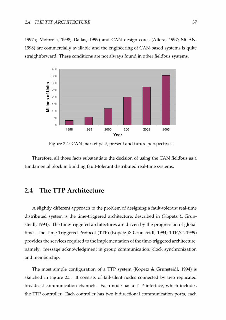
2.4. THE TTP ARCHITECTURE 37
1997a; Motorola, 1998; Dallas, 1999) and CAN design cores (Altera, 1997; SICAN,
1998) are commercially available and the engineering of CAN-based systems is quite
straightforward. These conditions are not always found in other fieldbus systems.
0
50
100
150
200
250
300
350
400
1998 1999 2000 2001 2002 2003
Year
Mili
ons
of U
nits
Figure 2.4: CAN market past, present and future perspectives
Therefore, all those facts substantiate the decision of using the CAN fieldbus as a
fundamental block in building fault-tolerant distributed real-time systems.
2.4 The TTP Architecture
A slightly different approach to the problem of designing a fault-tolerant real-time
distributed system is the time-triggered architecture, described in (Kopetz & Grun-
steidl, 1994). The time-triggered architectures are driven by the progression of global
time. The Time-Triggered Protocol (TTP) (Kopetz & Grunsteidl, 1994; TTP/C, 1999)
provides the services required to the implementation of the time-triggered architecture,
namely: message acknowledgment in group communication; clock synchronization
and membership.
The most simple configuration of a TTP system (Kopetz & Grunsteidl, 1994) is
sketched in Figure 2.5. It consists of fail-silent nodes connected by two replicated
broadcast communication channels. Each node has a TTP interface, which includes
the TTP controller. Each controller has two bidirectional communication ports, each

38 CHAPTER 2. STATE OF THE ART
Node n
TTPInterface
Node 2Node 1
TTPInterface
TTPInterface
TTP Redundant Channels
Figure 2.5: The basic architecture of a TTP system
one connected to a given TTP replicated channel. A sending node sends two identical
frames, one on each of the replicated channels. It is assumed that nodes synchronize
their clocks within a known precision.
Media-access is controlled by a conflict-free TDMA strategy. In the TDMA scheme,
time is divided into slots of not necessarily equal duration and each node is assigned a
unique slot where only this node is allowed to send. Once access to the shared medium
has been granted to all nodes (TDMA round), the access pattern is repeated.
Each TTP node contains a common message dispatching table specifying, among other
information, the type of message (initialization/normal), the length and the point in
time at which each message should be sent/received (TTP/C, 1999).
In TTP, the operation of the membership service is the basis for the implementation
of atomic multicast communication (Kopetz & Grunsteidl, 1994). Each node maintains
a reference to each currently active node in a membership vector (TTP/C, 1999). A node
adds itself in the set of active nodes (membership vector), when it is about to send. A
recipient, adds the sending node to its membership vector, whenever a correct frame
is received in the corresponding TDMA slot. The validation of a frame correctness,
through a 16-bit CRC, includes the contents of the frame and the contents of the local
membership vector. That means, for a frame to be correct, the membership vector of the
sender and of the recipients must be identical. A node is removed from the membership
vector, when no valid frame is received from the node, at the given slot.

2.4. THE TTP ARCHITECTURE 39
After a node, say ) , has sent a given frame,�+*-,/.
, it executes an implicit
acknowledgment� � algorithm, which waits for the next transmissions in the TDMA round
(TTP/C, 1999). The execution of the implicit acknowledgment algorithm is completed
when some node, say 0 , positively confirms the reception of� *-,/.
. Both nodes ) and 0will be added to the membership vector, as active members. In case other node, say 1 ,has negatively confirmed the reception of frame
�2*3,.before, 1 will be removed at this
point from the sender membership vector. On the other hand, the sender, ) , is obliged
to remove itself from its membership vector, whenever: frame reception has been neg-
atively confirmed; two nodes agree with the sender on a valid membership vector� �
from which the sender has been removed, before some other node acknowledges the
reception of frame� *3,.
.
If the sender is not able to complete the implicit acknowledgment algorithm before its
sending slot, in the next TDMA round, the node is shutdown due to a clique avoidance
algorithm (Bauer & Paulitsch, 2000; TTP/C, 1999). The clique avoidance algorithm uses
two counters, accounting for: the number of frames accepted by the node during the
last TDMA round; the number of frames rejected within the same period. A node
is shutdown if the number of rejected frames is larger than or equal to the number
of frames accepted by the node within the last TDMA round. The clique avoidance
algorithm is designed to perform the shutdown of nodes with a faulty receiver and it
aims to avoid network partitioning into cliques, i.e. two or more disjoint subsets of
nodes which are able to communicate only within each other (Bauer & Paulitsch, 2000).
In TTP, one can define a set of different operational envelopes. Each one of these
envelopes is known in TTP terminology as a mode. The protocol supports the change
from one mode to another consistently at all nodes (Kopetz & Grunsteidl, 1994).
The procedures required to initialize network operation are similar to those allow-
ing node reintegration. The system engineer must ensure that at least some nodes send
initialization frames periodically (Kopetz & Grunsteidl, 1994).
�%�Meaning that, no explicit acknowledgment message is actually exchanged. Rather, agreement on
local/remote membership vectors is checked, through CRC calculation.�4�At this point: the sender is removed from the membership vector; the two nodes are included as
active members, in the sender membership vector. The implicit acknowledgment algorithm is completed.The sender is allowed to be reintegrated within a given number of TDMA rounds (TTP/C, 1999).

40 CHAPTER 2. STATE OF THE ART
The protocol provides the fault-tolerant internal synchronization of the local clocks
to generate a global time-base within a microsecond range.
2.5 TTP versus CAN
A comparison of the TTP and CAN protocols is summarized in Figure 2.6. We use an
adaptation of the analysis presented in (Kopetz, 1998). Several parameters, concerning
the network operation and the service interface, are included in the comparison of the
two protocols.
Parameter TTP - Time-Triggered CAN StandardProtocol Layer
Maximum Rate 2 Mbps 1 MbpsNetwork operation transmission line quasi-stationary busMedia access control TDMA CSMA/DCRFrame efficiency 14.3% - 87.9% 45.3% - 59.2%Error detection value and value domain
time domainsFault confinement active error active
inactive error passive, bus offOmission handling masking detection/recovery
frame diffusion frame retransmissionMedia redundancy no noChannel redundancy yesBabbling idiot avoidance bus guardian not providedCommunications broadcast broadcastMembership service provided not providedClock synchronization in 576 rangeReplica determinism providedTemporal composability supported
Figure 2.6: Comparison of TTP and CAN
For the evaluation of frame efficiency, we assume that the 29-bit identifier� � of a
CAN frame carries semantically relevant information. A similar approach is followed
�4�This corresponds, in CAN terminology, to the utilization of CAN 2.0B (BOSCH, 1991; ISO, 1993).

2.5. TTP VERSUS CAN 41
in TTP with regard to the 3-bit mode change field (TTP/C, 1999).
The use of a priori message scheduling knowledge allows the detection in TTP of
errors in the time domain. In CAN, a similar functionality has to be built on top of
the bare network protocol and requires the use of additional services, such as a global
notion of time.
In regard to the confinement of faults, we assume a simplified description of the
operation of network controllers considering only two states: active, where the node is
fully integrated in network operation, being able to send and receive frames; inactive,
where the node has some severe restrictions or it is not even allowed to send/receive
frames. In CAN, the inactive state includes the error passive and bus off states (BOSCH,
1991; ISO, 1993). In TTP, the inactive state comprises a large number of states, including
those required for node start-up (TTP/C, 1999).
A node that does not respect the timing properties of a given message scheduling
(e.g. by queuing a given message too often or exceeding the given maximum size)
has been dubbed a babbling idiot. In TTP, babbling idiot avoidance has been achieved
through an independent bus guardian, which aims to prevent a node of transmitting out
of the preallocated time slot (Temple, 1998). Though the standard CAN layer does not
include mechanisms for babbling idiot avoidance, there are no fundamental obstacles to
the implementation of such mechanisms in CAN. As a matter of fact, possible solutions
to the problem have been described in (Tindell & Hansson, 1995; Broster & Burns,
2001a).
In TTP, the availability of channel redundancy results in essence from network
interface modular duplication, at the TTP controller level (TTP, 2001). Some commer-
cially available CAN microcontrollers include dual CAN interfaces (Motorola, 1996;
Motorola, 1998; Dallas, 1999). So, a similar design approach may be (and it will be)
followed in the implementation of dependable CAN-based systems and therefore the
absence of CAN standard network redundancy mechanisms does not constitute a basic
limitation of the CAN fieldbus.
On the other hand, the provision of reliable communications and other high level
characteristics, such as replica determinism, is addressed from an architectural view-

42 CHAPTER 2. STATE OF THE ART
point, in the Time-Triggered Architecture (Kopetz & Bauer, 2002), which is built on top
of TTP. Naturally, such architectural issues can also be addressed in a “CAN system”,
based on the CAN fieldbus.
Replica determinism means that replicated nodes must perform the same state
changes at about the same time. Replica determinism is needed to implement fault-
tolerance by active redundancy and facilitate system test (Kopetz, 1998). The availabil-
ity of atomic multicast and clock synchronization services are of fundamental impor-
tance to guarantee replica determinism.
A system is said to be composable with respect to a specified property if the system
integration will not invalidate this property once the property has been established at
the subsystem level (Kopetz, 1998). One example of such kind of properties is time-
liness. Temporal composability is a property of time-triggered architectures (Kopetz,
1998). This issue has not been addressed in CAN-based systems.
On the other hand, it should be noted that the engineering of TTP-based systems
requires the use of specialized design tools (TTP, n.d.) and that the availability of
commercial TTP controllers is currently restricted to a single source (TTP, 2001).
In (Kopetz, 1998), Kopetz concludes that CAN is well suited for soft real-time
systems where flexibility is important, while TTP is most appropriate for the design
of composable hard real-time systems with high dependability requirements. Such
a claim is slightly unfair in regard to the CAN fieldbus, given CAN has not been
specifically designed to achieve the high levels of dependability, which were always a
goal in TTP.
However, one needs to realize that what it is really missing in the low-cost CAN
standard architecture to secure the levels of dependability of TTP-based systems, is
a given set of reliability, availability and timeliness properties, which can be easily
provided off-the-shelf, through the use of some additional software/hardware compo-
nents.

2.6. DESIGN OF DEPENDABLE CAN-BASED SYSTEMS 43
2.6 Design of Dependable CAN-based Systems
The standard CAN layer can (and should) then be complemented/enhanced with
the means required to secure the strict reliability, availability and timeliness guarantees
needed by highly fault-tolerant real-time systems and applications.
This implies the provision of: a set of semantically rich reliable communication
services, such as group communication, node failure detection and membership, fault-
tolerant clock synchronization and global time; resilience to network partitioning,
through redundancy; guarantees of a reliable hard real-time operation, in the pres-
ence of network errors.
The objective of this dissertation is to study how those mechanisms can be effectively
implemented in the realm of the CAN fieldbus.

44 CHAPTER 2. STATE OF THE ART

Controller Area Network
The Controller Area Network (CAN) (BOSCH, 1991; ISO, 1993) is a standard com-
munication bus intended for message transaction in small-scale distributed environ-
ments. Originally designed for automotive applications, the CAN fieldbus has assumed
increasing importance and widespread acceptance in areas as diverse as shop-floor con-
trol, robotics, medical systems, railways, automotive, avionics and aerospace.
The standard CAN fieldbus is structured according to the Open System Interconnec-
tion (OSI) reference model, through the use of a collapsed three-layer communication
stack made from the physical, data-link and application layers, on top of which the con-
trol applications are executed (cf. Figure 3.1). The CAN fieldbus uses a multi-master
architecture over a bus infrastructure that together with a non-destructive message
arbitration scheme and extensive error checking capabilities provides a relevant set of
correctness, ordering and timeliness attributes.
Such a set of attributes, traditionally not secured by the MAC sub-layer of LANs
and other fieldbuses, justify the generalized notion that CAN is a very robust real-time
network. However, some of those attributes have been misinterpreted and sometimes
used thoughtlessly, for example to substantiate the claim that CAN is able to extremely
reliable communication (Peraldi & Decotignie, 1995; Poledna, 1995; Hilmer et al., 1997),
an assertion acceptable only in applications with modest requirements on system re-
liability. In fact, the CAN fieldbus exhibits, together with its exceptional properties, a
set of severe dependability shortcomings that cannot be ignored in the design of CAN-
based fault-tolerant real-time distributed systems, under the risk that those systems
would function incorrectly (Rufino et al., 1998b; Rufino et al., 1999d).
Hence, an accurate analysis of the CAN standard layer, establishing (even if in an
45

46 CHAPTER 3. CONTROLLER AREA NETWORK
Transmission Medium
Physical Layer (PHY)
Data Link Layer
ISO 11898 StandardBosch CAN Specification 2.0
CANCommunications
Host ControlApplications
MACLLC{
Application Layer
(e.g. CAL/CANopen)
(e.g. CORBA)
- Industry Standard Solutions
- Middleware Technologies
- Specialized Protocols
Figure 3.1: CAN three-layer protocol stack and node architecture overview
informal basis) the set of properties that one may actually expect from the CAN protocol
and identifying in a clear way its dependability weaknesses, is of crucial importance.
The former defines the CAN own properties that can (and should) be exploited in the
design of CAN-based systems. The latter enumerates the problems that need to be
addressed to secure dependability and timeliness.
In our approach to the design of an embedded fault-tolerant real-time distributed
system around the CAN fieldbus (Rufino et al., 1998a; Rufino et al., 1999d), the additional
mechanisms required to secure the strict dependability and timeliness guarantees of
highly fault-tolerant real-time applications are preferably integrated at the lowest levels
of the system architecture, where the implementation of simple and effective solutions
is feasible. Such an approach allows also higher layers to take advantage from the
availability of those low-level mechanisms, in order to: simplify their own design;
offer an interface yielding enhanced dependability and timeliness guarantees.
For example, the high-level protocols that constitute the application layer of CAN-
based systems (cf. Figure 3.1) may include components whose service interface is
in conformity with: one of the protocol suite solutions�
available from the industry;
emerging middleware technologies, such as the Common Object Request Broker Ar-
chitecture (CORBA) (OMG, 2001; Kim et al., 2000). In a fault-tolerant real-time system,
�This includes: the industry standard CAN Application Layer (CAL) and application programming
interface CANopen (Boterenbrood, 2000); SDS, the Smart Distributed System (SDS, 1996); DeviceNet;CAN Kingdom (Fredriksson, 1995). A fairly comprehensive overview of these CAN high-level protocolsand a comparison of their characteristics can be found in (Lennartsson, 1995; Etschberger, 1997).

3.1. CAN PHYSICAL LAYER 47
those application layer entities need to be complemented with the mechanisms required
for the management of dependability � and timeliness, which may call for specialized
protocols (Wolfe et al., 1997; Rufino et al., 1999d).
In any case, the central issue of this chapter is the analysis of lower levels of the
CAN architecture (Figure 3.1), addressing with particular attention the real-time and
dependability characteristics of the physical and data-link layers, as per the standard
(BOSCH, 1991; ISO, 1993). The chapter is organized as follows: the fundamental
aspects of the CAN physical layer are analyzed in Section 3.1; Section 3.2 describes
the CAN data-link layer functions, namely the medium access control (MAC) method
and the CAN message arbitration and retransmission schemes � ; finally, in Section 3.3,
we analyze the error checking and fault confinement mechanisms of CAN and their
relevance to the provision of CAN dependable communications.
3.1 CAN Physical Layer
The Physical Layer (PHY) has the responsibility of ensuring the transfer of bits of
information between the different nodes in the network. Relevant issues do include:
transmission medium and bus signaling levels; bit encoding and timing; synchroniza-
tion of the local receiver circuitry with the bit stream being transfered.
Transmission medium
In the original Robert Bosch CAN specification (BOSCH, 1991), no particular media
or bus signaling levels were defined, thus allowing different design options for the CAN
physical layer. The CAN bus signaling levels were defined only within the scope of the
International Organization for Standardization (ISO) international standard (ISO, 1993),
complemented by the industry standard CiA DS 102 (CiA, 1992; CiA, 1994), in regard
to the specification of the transmission medium and node connector characteristics.
�For example, replication management.�This is a function of LLC, the data-link Logical Link Control sub-layer (ISO, 1985a).

48 CHAPTER 3. CONTROLLER AREA NETWORK
Differential Two-Wire Bus Cable
Node nNode 1
Termination Termination
CAN_H
CAN_L
Physical Layer
"medium layer"
CANInterface
CANInterface
Physical Layer
Data-Link Layer
e.g. CAN transceiver
Tx Rx
CAN_H CAN_L
CANcontroller
mediuminterface
Figure 3.2: CAN physical layer and node architecture
Therefore, most of nowadays existing CAN implementations use a differential two-
wire bus line terminated at both ends by its characteristic impedance (cf. Figure 3.2),
as specified in (CiA, 1992; CiA, 1994). Each node interfaces the differential bus line
using off-the-shelf bus transceivers (e.g. (Philips, 1994; Alcatel, 1995)), in conformity
with the ISO specification (ISO, 1993). However, alternative designs are possible for the
CAN physical layer infrastructure. For example: a physical layer in conformity with
the Electronic Industries Association (EIA) RS-485 bus signaling standard � , is feasible;
in safety-hazard environments, the transmission medium can be galvanically isolated
through the use of fast optocoupling technology (Agilent, 1999); the use of (low-cost)
optical fibers, offering high robustness to electromagnetic interference, is a practicable
solution (Rucks, 1994).
This opens room for a large set of applications in a wide range of environments.
Bit signaling and encoding
In CAN, bus signaling takes one out of two possible values: recessive, otherwise the
state of an idle bus, occurs when all competing nodes send recessive values; dominant,
which only needs to be sent by one node to stand on the bus. That means, a dominant
value always overwrites a recessive value. This behavior comes from the wired-and
�The standard RS-485 bus (EIA, 1978), using differential signals with a voltage range higher than
CAN, offers a higher noise immunity.

3.1. CAN PHYSICAL LAYER 49
nature of the CAN physical layer and constitutes a very interesting and useful property,
extensively exploited: in the CAN protocol itself, to resolve conflicts in the access to the
shared transmission medium; in the design of fault-tolerant real-time communication
systems, to enforce a relevant set of dependability and real-time attributes � (Rufino
et al., 1998a; Rufino et al., 1999d).
Each bit is transmitted using the NRZ � code. The use of this encoding method is in
conformity with the CAN protocol wired-and multiple access property and given that
the NRZ code exhibits a low spectral density, it also allows a good utilization of the
transmission medium bandwidth.
Bit timing and synchronization
Since the NRZ code does not allow the self-extraction of bit timing information, the
CAN protocol must rely on an alternative solution to ensure the correct synchronization
of the local receiver circuitry with the incoming bit stream. The fundamental issues of
such a process are described next.
The nominal bit time, which is associated with a logical bit slot in Figure 3.3, is
divided into four non-overlapping segments. The propagation time segment (PRP) takes
into account the physical level delays: the bus propagation time plus the transmitter
and receiver delays at the medium interface devices. The idea is to give enough time for
signal stabilization along the bus before nodes perform sampling, which occurs at the
end of the PH1 segment (Figure 3.3). Bus signal transitions are expected to lie within
the synchronization segment (SYNC). Deviations from this ideal behavior produce phase
errors which are compensated for by using one of the two phase segments as elastic
buffers: the PH1 segment is lengthened in fast receivers, upon the detection of a phase
error; slow receivers compensate phase errors by shortening PH2.
�For example: resilience to network medium partitioning, through redundancy (Rufino et al., 1999b);
urgency constrained distributed scheduling of application-level messages (Tindell & Burns,1994b; Livaniet al., 1998; Zuberi & Shin, 1997).�
Non-Return-to-Zero (NRZ), a code format in which: a binary signal is mapped onto a two-levelsignal representation (the dominant/recessive values, in the particular case of the CAN fieldbus); withinone and the same bit time, the encoded signal level does not change.
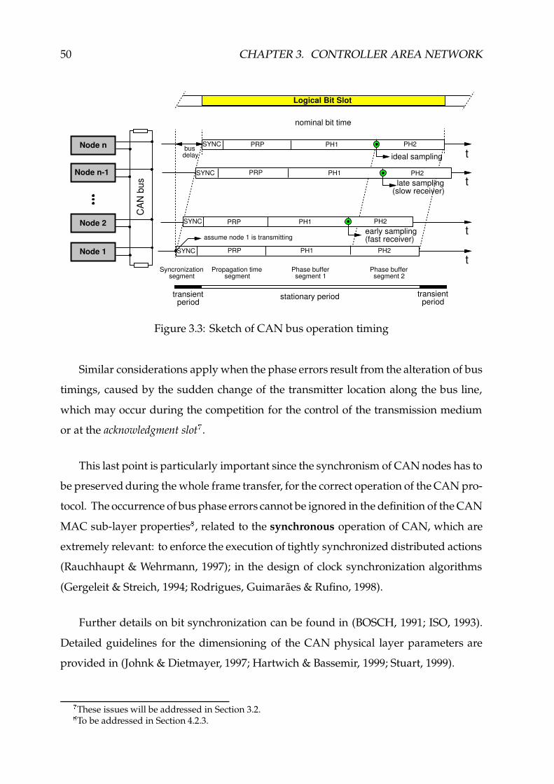
50 CHAPTER 3. CONTROLLER AREA NETWORK
SYNC PRP PH1 PH2
early sampling(fast receiver)
PRP PH1 PH2
t
t
t
tC
AN
bus
assume node 1 is transmitting
SYNC PRP PH1 PH2
Phase buffer segment 2
Propagation time segment
Phase buffer segment 1
Syncronization segment
transient period
transient period
stationary period
Node 1
SYNC PRP PH1
busdelay
nominal bit time
ideal sampling
late sampling(slow receiver)
PH2
Node 2
Node n-1
Node n
SYNC
Logical Bit Slot
Figure 3.3: Sketch of CAN bus operation timing
Similar considerations apply when the phase errors result from the alteration of bus
timings, caused by the sudden change of the transmitter location along the bus line,
which may occur during the competition for the control of the transmission medium
or at the acknowledgment slot � .
This last point is particularly important since the synchronism of CAN nodes has to
be preserved during the whole frame transfer, for the correct operation of the CAN pro-
tocol. The occurrence of bus phase errors cannot be ignored in the definition of the CAN
MAC sub-layer properties , related to the synchronous operation of CAN, which are
extremely relevant: to enforce the execution of tightly synchronized distributed actions
(Rauchhaupt & Wehrmann, 1997); in the design of clock synchronization algorithms
(Gergeleit & Streich, 1994; Rodrigues, Guimaraes & Rufino, 1998).
Further details on bit synchronization can be found in (BOSCH, 1991; ISO, 1993).
Detailed guidelines for the dimensioning of the CAN physical layer parameters are
provided in (Johnk & Dietmayer, 1997; Hartwich & Bassemir, 1999; Stuart, 1999).
�These issues will be addressed in Section 3.2.!To be addressed in Section 4.2.3.

3.1. CAN PHYSICAL LAYER 51
Quasi-stationary operation
With exception of the transient periods at bit boundaries, a single bit is present in
the CAN bus line at a time. As a consequence, all nodes get the same bit – with regard
to the incoming stream – when sampling the bus " . Such kind of operation is known as
quasi-stationary.
A major consequence of the quasi-stationary operation of the bus is that the network
maximum length depends on the data rate. Typical values for the CAN fieldbus are:
40m @ 1 Mbps; 1000m @ 50 kbps.
The quasi-stationary operation of CAN and the consequent “simultaneity” of bus
bit sampling, imposes a set of physical layer properties (to be formally defined in
Section 4.2.2) which are required by the CAN protocol for arbitrating accesses to the
shared transmission medium, bus state monitoring and data transfer.
Those physical layer properties do represent the essence of CAN bus operation
and are of utmost importance, given they can be effectively exploited to enhance CAN
dependability and real-time attributes (e.g. (Rufino et al., 1999b)).
Physical layer fault-tolerance
The mechanisms specified for the CAN physical layer in (ISO, 1993) allow the
provision of resilience against a set of medium failures, such as one-wire interruption,
two-wire short-circuit, or one-wire short-circuit either to power or ground.
Those mechanisms need to be implemented in special-purpose medium interfaces
(e.g. (Philips, 1997b)) that, by switching from the normal differential operation to a
single-wire mode, allow CAN bus operation to proceed, though with a reduced signal-
to-noise ratio. However, one limitation of the currently available devices (e.g. (Philips,
1997b)) is that they are intended for low-speed communication (up to 125 kbps) with
no more than 32 nodes.
#Although the sampled value may not be the same at all nodes, due to errors. Examples of causes
for erroneous bit sampling are: electromagnetic interference, loss of synchronism or defective receivercircuits.
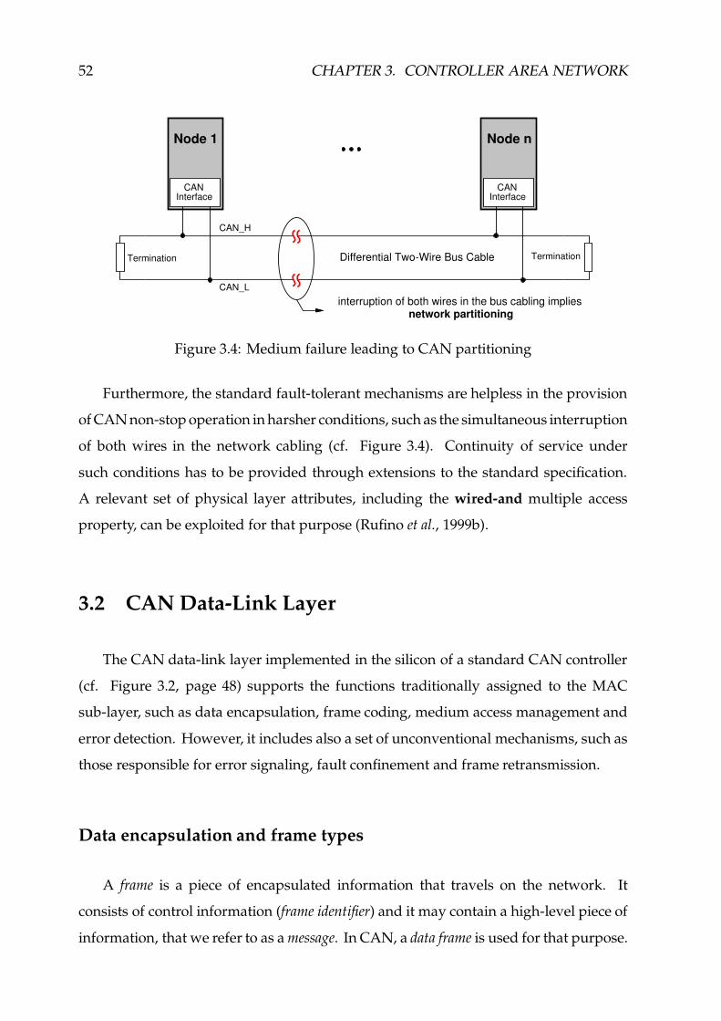
52 CHAPTER 3. CONTROLLER AREA NETWORK
CAN_H
CAN_L
Node 1
CANInterface
Node n
Differential Two-Wire Bus CableTermination Termination
CANInterface
interruption of both wires in the bus cabling impliesnetwork partitioning
Figure 3.4: Medium failure leading to CAN partitioning
Furthermore, the standard fault-tolerant mechanisms are helpless in the provision
of CAN non-stop operation in harsher conditions, such as the simultaneous interruption
of both wires in the network cabling (cf. Figure 3.4). Continuity of service under
such conditions has to be provided through extensions to the standard specification.
A relevant set of physical layer attributes, including the wired-and multiple access
property, can be exploited for that purpose (Rufino et al., 1999b).
3.2 CAN Data-Link Layer
The CAN data-link layer implemented in the silicon of a standard CAN controller
(cf. Figure 3.2, page 48) supports the functions traditionally assigned to the MAC
sub-layer, such as data encapsulation, frame coding, medium access management and
error detection. However, it includes also a set of unconventional mechanisms, such as
those responsible for error signaling, fault confinement and frame retransmission.
Data encapsulation and frame types
A frame is a piece of encapsulated information that travels on the network. It
consists of control information (frame identifier) and it may contain a high-level piece of
information, that we refer to as a message. In CAN, a data frame is used for that purpose.

3.2. CAN DATA-LINK LAYER 53
However, a frame may consist of control information only, such as a remote frame,
which has no data field and may be used in CAN to request the transmission of a data
frame from one or more remote nodes. In this sense, the remote frame can be thought as
intended to be used for control purposes, by the protocols above the MAC sub-layer.
Frame identifiers
In CAN, the frame identifiers assigned to data frames must be unique (BOSCH,
1991; ISO, 1993). However: the same identifier may be used in data and remote frames,
the distinction being made through the remote transmission request (RTR) bit (Figure 3.5);
several nodes may simultaneously transmit the same remote frame�8$
.
DLCSOF IDESRR Extended Identifier RTR rv1 rv0
4bit1bit 11bit 1bit 1bit 18bit 1bit 1bit 1bit
Base Identifier
only exists in CAN 2.0B{
Start-Of-Frame delimiter
RTR rv1
d d
r d
r r
CAN 2.0A data frame
CAN 2.0A remote frame
CAN 2.0B frameSRR IDE
d - dominantr - recessive
Remote Transmission Requestd - data framer - remote frame
Figure 3.5: Fragment of a CAN data/remote frame showing the identifier structure
The CAN specification (BOSCH, 1991; ISO, 1993; ISO, 1995) allows two differ-
ent values for the length of data/remote frame identifiers (Figure 3.5): standard 11-bit
identifiers (CAN 2.0A); extended 29-bit identifiers (CAN 2.0B). The distinction between
the two slightly different frame formats is made through the SRR (substitute remote re-
quest) and IDE (identifier extension) bits, as illustrated in Figure 3.5 and comprehensively
described in Appendix B (page 233).
In our approach to the design of a CAN-based fault-tolerant real-time system, the
frame identifier also includes message-related control information. As a consequence,
�%&Provided that the Data Length Code (DLC) field (Figure 3.5) is equal for all nodes. Otherwise, an
un-resolvable collision would prevail. The CAN specification allows any value within the admissiblerange 9 :<;>=@? , to be used in the DLC field of remote frames (cf. Appendix B).

54 CHAPTER 3. CONTROLLER AREA NETWORK
we may refer to frame and message identifiers interchangeably. The fault-tolerant protocol
suite above the MAC sub-layer (Rufino et al., 1998a; Rufino et al., 1998b), makes use of
the message-related control information�'�
, to ensure the uniqueness of frame identifiers.
Furthermore, we assume the utilization of the CAN 2.0B extended format (BOSCH,
1991; ISO, 1993; ISO, 1995): the identifier extension (Figure 3.5) is used to carry the
message-related control information, leaving the data field free to hold pure data. A
detailed specification of how the message-related control information is encapsulated
within the frame identifier is provided in Appendix C.
Frames with no identifiers
The CAN protocol specifies the use of two special frames, which have no identifier
fields, for data-link layer control purposes: an error frame is issued, by the CAN
controller, whenever a node detects an error in a frame broadcast process; an overload
frame is issued, upon a request from the protocol entities above the MAC sub-layer, to
extend the interval between two consecutive data/remote frame transmissions.
The issuing of an overload frame, by the CAN controller, is due when the minimum
bus idle period that precedes the transmission of a data/remote frame is violated or
when a dominant value is detected at the last bit of a frame, by the receiver of a
data/remote frame or by any node upon the issuing an error/overload frame (cf.
Figure 3.11, in page 61).
A comprehensive description of CAN error and overload frame formats and the
analysis of the corresponding timings is provided in Appendix B (page 238).
Frame non-destructive arbitration
In CAN, the frame/message identifiers assigned to data frames are unique. This
feature, together with the wired-and behavior, is exploited to resolve conflicts in the
�(�In conformity with the specified in Appendix C, this includes: the sender node unique identifier;
the protocol identifier; protocol-level message type and sequence number.

3.2. CAN DATA-LINK LAYER 55
access to the shared transmission medium, whose access policy is a carrier sense multiple
access with deterministic collision resolution (CSMA/DCR) scheme:
� nodes defer the start of a frame transmission, until the bus is idle;
� several nodes may then jump on the bus at the same time, but while transmitting
the frame identifier, each node monitors the bus;
� for every bit, if the transmitted bit is recessive and a dominant value is monitored
(e.g. Node ) , at bit 7, Figure 3.6), the node gives up transmitting and starts to
receive incoming data;
� the node transmitting the frame with the lowest identifier (Node � , from bit 3 on,
Figure 3.6), goes through and gets the bus.
SOF
10 9 8 7 6 5 4 3 2 1 0
Identifier bits
0 1 0 1 1 0 0 1 1 0 1 0
0 1 0 1 0 0 1 1 0 1 1 1
0 1 0 1 0 0 1 1 1 0 0 0
arbitration loss
arbitration loss
mid: 538 hexNode 1
mid: 537 hexNode k
Bus Staterecessive (logical one)
dominant (logical zero)
mid: 59A hexNode n
mid: message identifier
Figure 3.6: CAN non-destructive arbitration
This means that the collision resolution mechanism, arbitrating the access to the
shared transmission medium in the CAN fieldbus, is: non-destructive, given that the
transmission of the frame with the lowest identifier, once started, is not disturbed by
transmit requests from other nodes (cf. Figure 3.6); deterministic, in the sense that it
allows to secure a bounded and known delay from request to transmission of a frame,
given the worst-case load conditions assumed.
Moreover, the CAN medium access control method makes possible the real-time
distributed scheduling of message transmit requests (Tindell & Burns, 1994b; Livani

56 CHAPTER 3. CONTROLLER AREA NETWORK
et al., 1998; Zuberi & Shin, 1997), provided message urgency is included in the most
significant bits of the frame identifier, as specified in Appendix C.
Frame coding
In order to avoid the transmission of long sequences of bits with the same value� �
outgoing data/remote frames are subject to a bit-stuffing coding scheme that prevents
more than five consecutive bits of identical polarity to be transmitted, through the
automatic insertion of a bit of opposite value (Figure 3.7). The bit-stuffing coding is
performed from the start-of-frame delimiter up to the end of the 15-bit CRC sequence
(cf. Appendix B). The CRC delimiter, the acknowledgment field and the end-of-frame
(EOF) delimiter exhibit a fixed form, not subject to bit-stuffing coding (Figure 3.8).
Node n0 1 1 1 1 1 0 1 1 1 0 0 0
Bus State
0 1 1 1 1 1 1 1 1 0 0 0 row data
stuffed stream
recessive (logical one)
dominant (logical zero)
Figure 3.7: CAN bit-stuffing coding
The use of bit-stuffing coding makes the duration of data/remote frames to de-
pend on frame length and frame contents (Rauchaupt, 1994). A detailed analysis of
data/remote frame durations is provided in Appendix B (page 235).
The bit-stuffing coding rule excludes any sequence longer than five consecutive bits
of identical polarity from being part of a valid data/remote frame transfer, exception
made to the end-of-frame sequence (Figure 3.8). Specific sequences, not obeying to
the bit-stuffing coding rule, are used to define: the multi-field fixed form sequence
that ends every data/remote frame (cf. Figure 3.8); the 6-bit fixed form sequence of
the error and overload flags (Appendix B, page 234); the 8-bit fixed form sequence of
consecutive recessive bits that made up the error/overload frame delimiters.
�%�The absence of enough transitions in a bit stream would prevent an accurate synchronization of the
receiver clock, that locally controls the bus sampling process, with the incoming bit stream.

3.2. CAN DATA-LINK LAYER 57
CRC Sequence CRCDel
ACKSlot
ACK Del
EOF Delimiter
EFS - End-of-Frame Sequencebit-stuffing coding
nominal bit valuesr d r r r r rrr r
d - dominantr - recessive
Figure 3.8: The end-of-frame sequence does not obey to bit-stuffing coding
Those multi-bit fixed form sequences define unique patterns, detectable at the PHY-
MAC interface, which unambiguously identify: the occurrence/signaling of a network
error; the correct reception/termination of a data/remote frame. These features are of
utmost importance to the design of CAN-based systems with enhanced dependability
and real-time attributes (Rufino et al., 1998a; Rufino et al., 1999b).
Frame acknowledgment
The CAN protocol uses a combination of positive and negative acknowledgment
schemes to signal whether or not the contents of a data/remote frame are correct.
CRC Sequence CRCDel
ACKSlot
ACK Del EOF Delimiter
issued recessive by the transmitter
changed to dominant by nodes receiving a correct data/remote frame
r dframe is correct:
nodes signal the lack of a dominant bus level at the ACK-slot
receivers signal the local CRC error
local CRC error
global CRC error r
start of error signaling
frame is incorrect
d - dominantr - recessive
r d
Figure 3.9: Frame acknowledgment and error signaling
The acknowledgment process is initiated by the transmitter, which is constrained to
the issuing of a recessive level, during the acknowledgment slot of a data/remote frame
(Figure 3.9). Every node receiving a data/remote frame without errors� � , up to the
�4�This includes a correct CRC checking (Section 3.3).

58 CHAPTER 3. CONTROLLER AREA NETWORK
CRC delimiter, is compelled to positively acknowledge the frame reception, through
the issuing of a dominant bit level, at the acknowledgment slot. In the absence of errors,
this changes the bus level from recessive to a dominant value, and defines a fixed form
bit sequence that identifies the correct transfer of a data/remote frame.
If the data/remote frame transfer is disturbed by errors, different (error) signaling
sequences take place. A node receiving a frame with an incorrect CRC does not modify
the value of the acknowledgment slot. However, the subset of the nodes� � receiving the
frame correctly, may impose a dominant value at the acknowledgment slot. In this case,
the (local) CRC error is signaled through the transmission of an error frame, that starts
at the bit following the acknowledgment delimiter (Figure 3.9). A recessive value at the
acknowledgment slot means that the CRC error has been detected by all receivers. The
signaling of the (global) CRC error starts at the acknowledgment delimiter.
The distinction of local/global errors is of fundamental importance to the operation
of the standard CAN fault confinement mechanisms, to be discussed in Section 3.3.
Frame retransmission
The CAN protocol automatically schedules a data/remote frame for retransmission:
after a loss in an arbitration process; upon the detection of an error.
The first condition is a natural consequence of the CAN medium access mechanism
and is usual in other real-time LANs (LeLann, 1987) and fieldbuses (LON, 1995), using
carrier sense multiple access schemes.
The second feature is not commonly implemented in the silicon of LAN and fieldbus
controllers. Roughly, it corresponds to the functionality provided by the LLC sub-layer
acknowledged connectionless service (Pimentel, 1990). In CAN, the transmit retry
on demand of error detection mechanisms aims to secure frame delivery either to
all nodes or to no node. The use of simple error detection/signaling mechanisms,
as the bit-wise frame acknowledgment scheme, allows an optimum utilization of the
network bandwidth (a scarce resource in CAN). Upon the detection of an error in
�4�This subset may have only one element.

3.2. CAN DATA-LINK LAYER 59
a frame broadcast process, the frame is: discarded by the receivers; scheduled for
retransmission, by the transmitter.
Frame validation
The correctness of CAN data/remote frame transfers is monitored in a slightly
different way by the transmitter and the receiver nodes, as per the standard (BOSCH,
1991; ISO, 1993):
“The point of time at which a frame is taken to be valid, is different for the transmitter
and the receivers of the frame. Transmitter: the frame is valid for a transmitter, if
there is no error until the end of End-Of-Frame. Receivers: the frame is valid for
receivers, if there is no error until the last but one bit of End-Of-Frame.”
In CAN, a correct data/remote frame ends with a given sequence of recessive bits
(Figure 3.8, page 57). The use of a recessive sequence allows the monitoring of error
situations at each bit of End-Of-Frame (EOF) delimiter� � . In addition, the end-of-frame
delimiter needs to have a length long enough to allow the detection of a lack of error
signaling (cf. Figure 3.10), after having induced a violation of the bit-stuffing coding
width, ACB4DFEHGIG . Given the acknowledgment delimiter also exhibits a recessive value, this
corresponds to a length of J(A B4DKEHGHG � �<L bits, within the EOF delimiter.
CRC Sequence CRCDel
ACKSlot
ACK Del EOF Delimiter
bit-stuffing coding violation
no error is signaled
stuffl Tx: recessive value
Rx: don’t care value
stuffl
Figure 3.10: End-Of-Frame (EOF) delimiter
�%�Provided error signaling involves the issuing of a dominant flag (cf. Section 3.3).

60 CHAPTER 3. CONTROLLER AREA NETWORK
However, one additional bit needs to be included in the end-of-frame delimiter� �
(Figure 3.10). Under correct operation, the transmitter should detect a recessive value
at such a bit. This secures that: an error detected at the J(A B4DKEHGHG � �ML DON bit of the EOF
delimiter by a subset of the active receivers� � , can also be detected by the transmitter,
given the signaling of the error by those receivers starts at the J>APB4DKEHGHGQ�SR L DON bit of the
EOF delimiter; in consequence, the transmitter starts its own error signaling process
and schedules the frame for retransmission. Should the transmitter and the receivers
obey to the same validity rule, those attributes would not be assured.
Unfortunately, the simple procedure used in the CAN protocol for frame validation
is not effective in all situations and may lead to: the generation of data frame duplicates,
when an error hits the last but one bit of the EOF delimiter; inconsistent data/remote
frame omissions, in case of transmitter failure (Rufino et al., 1998b).
These issues are of utmost importance to the design of highly dependable CAN-
based systems and applications (Rufino et al., 1999d) and they will be thoroughly
addressed in Section 4.1.1.
Interframe spacing
After the end of any frame transfer, each node is forced by the CAN protocol to
wait for a mandatory bus idle period, before it is allowed to start the transmission of a
data/remote frame. Such a sequence of recessive bits, known in CAN terminology as
intermission, has a nominal duration of three bit-times (Figure 3.11).
In conformity with the CAN 2.0B specification (BOSCH, 1991), a dominant value
at the last bit of the nominal intermission should be interpreted as a start-of-frame
delimiter. As a consequence, the intermission period has a minimum duration of two
bit-times (Figure 3.11). If no node has a frame queued for transmission, the interframe
space may exceed the nominal intermission period (Figure 3.11).
�%�Meaning, the total length of the EOF delimiter (in bits) is given by TVUXWZY\[]TF^C_F`bacaZd\e .� �This subset may have only one element. An active node starts the signaling of an error through the
issuing of an active error flag consisting of six consecutive dominant bits (cf. Section 3.3).
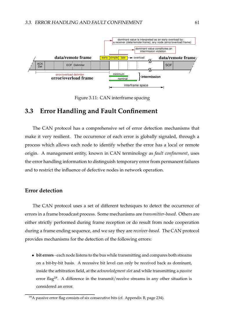
3.3. ERROR HANDLING AND FAULT CONFINEMENT 61
early simple latedata/remote frameSOF
data/remote frameEOF DelimiterACK
Del
error/overload delimitererror/overload frame
interframe space
dominant value is interpreted as an early overload by:a receiver (data/remote frame); any node (error/overload frame)
overload
dominant value constitutes an intermission violation
} intermissionminimum
nominal
Figure 3.11: CAN interframe spacing
3.3 Error Handling and Fault Confinement
The CAN protocol has a comprehensive set of error detection mechanisms that
make it very resilient. The occurrence of each error is globally signaled, through a
process which allows each node to identify whether the error has a local or remote
origin. A management entity, known in CAN terminology as fault confinement, uses
the error handling information to distinguish temporary error from permanent failures
and to restrict the influence of defective nodes in network operation.
Error detection
The CAN protocol uses a set of different techniques to detect the occurrence of
errors in a frame broadcast process. Some mechanisms are transmitter-based. Others are
either strictly performed during frame reception or do result from node cooperation
during a frame ending sequence, and we say they are receiver-based. The CAN protocol
provides mechanisms for the detection of the following errors:
f bit errors - each node listens to the bus while transmitting and compares both streams
on a bit-by-bit basis. A recessive bit level can only be received back as dominant,
inside the arbitration field, at the acknowledgment slot and while transmitting a passive
error flag� . A difference in the transmit/receive streams in any other situation is
considered an error.
�4!A passive error flag consists of six consecutive bits (cf. Appendix B, page 234).

62 CHAPTER 3. CONTROLLER AREA NETWORK
f bit-stuffing errors - a sequence of more than g B4DKEHGHG consecutive bits of identical level
is detected in a data or remote frame, up to the end of the 15-bit CRC sequence
(cf. Appendix B). Error signaling is started at the bit following the detection of the
bit-stuffing coding violation.
f CRC errors - data and remote frames include a 15-bit CRC sequence used to check
the integrity of frame contents. Should the CRC be correct, the node is obliged to
positively acknowledge frame reception, through the issuing of a dominant bus level
at the acknowledgment slot. Conversely, if the CRC is incorrect, the receiver starts the
transmission of an error frame at the bit following the acknowledgment delimiter, unless
an error signaling process due to other error condition has already been started.
f acknowledgment errors (ACK) - a node does not monitor a dominant level on the bus
during the acknowledgment slot. Error signaling starts at the acknowledgment delimiter.
All nodes cooperate in frame acknowledgment, though only the transmitter is strictly
obliged to the monitoring of the acknowledgment slot value (BOSCH, 1991; ISO, 1993).
f form errors - an illegal value is detected within a fixed form field of a frame. For
data/remote frames this includes the 1-bit CRC delimiter, the 1-bit acknowledgment
delimiter and the 7-bit end-of-frame delimiter. For error/overload frames that includes
both the flag and delimiter fields (cf. Figure 3.13, page 64). The transmission of an
error/overload flag is started at the next bit slot. A dominant value at the last bit of
a frame is not an error when: it is detected by the receiver of a data/remote frame; it
belongs to an error/overload frame. An early overload condition is then signaled.
Node Detection MechanismFunction bit error stuffing CRC ACK form overload
Transmission a � �Reception b � � � � �a – not strictly performed during arbitration, at the acknowledgment slot andwhile sending a passive error flag.b – monitoring is due only while sending an active error flag and whenissuing a dominant bit at the acknowledgment slot.
Figure 3.12: Summary of CAN error detection mechanisms
The operation of CAN error detection mechanisms is summarized in Figure 3.12.
The monitoring of bus values is performed by more than one mechanism: during a

3.3. ERROR HANDLING AND FAULT CONFINEMENT 63
frame ending sequence, when the node is transmitting; during frame CRC computa-
tions and at the acknowledgment slot, when the node assumes receiver functions. For
completeness, Figure 3.12 also includes the monitoring of overload conditions.
Overload detection
An overload signaling process must be started by a CAN controller, whenever: a
dominant value is detected at the last bit of a frame, by a receiver of a data/remote frame
or by any node upon the issuing of an error/overload frame; the minimum duration
of the interframe space has been violated (Figure 3.11). Given the CAN controller is
reacting to external events, we say this is a reactive overload process.
In conformity with the CAN specification (BOSCH, 1991; ISO, 1993), LLC sub-layer
protocol entities may request the increase of the interframe space length on account of
a receiver internal overload. This is achieved through the issuing of a LLC-requested
overload frame, at the first bit of intermission. Currently, no commercial CAN controller
(Intel, 1995; Motorola, 1998; Dallas, 1999) or CAN design core (Altera, 1997; SICAN,
1998) needs to make use of this feature.
Error and overload signaling
As a general rule, an error/overload signaling process is started at the bit slot which
immediately follows the detection of an error or overload condition. One exception
is the signaling of a local CRC error, which is delayed by the receiver of the incorrect
data/remote frame until the end of the acknowledgment delimiter. In addition, the
issuing of a LLC-requested overload frame must start at the first bit of intermission.
The error/overload process is initiated by the subset of the nodes� " detecting the
error or the overload condition, but all the nodes participate in the error/overload sig-
naling process. The fixed form of the error/overload flag either imposes a violation of
the bit-stuffing coding rule � $ or destroys a fixed form field in a frame. Each node issues
�%#This subset may have only one element.�(&Meaning that the duration of an error/overload flag TOaihkj(l (in bits) is given by Tmaihkj(ln[]TF^C_F`bacaHdpo�[rq bits.

64 CHAPTER 3. CONTROLLER AREA NETWORK
6 bits 8 recessive bits0-6 bitsFlag field Flag field Delimiter field
partially or non-overlapping flags
single or completely overlapping flags
overload flag
error flag active - 6 dominant bitspassive - 6 recessive bits
6 dominant bits
Figure 3.13: Error/overload frames
an error/overload flag and waits for the beginning of the error/overload delimiter. It
then completes the issuing of the error/overload delimiter through the transmission of
seven recessive bits (Figure 3.13).
Fault confinement
The fault confinement mechanisms provided by the CAN protocol are based on
two different error counters at each node, recording transmit and receive errors. These
counters have a non-proportional update method, with each error causing an increment
larger than the decrement resulting from a successful data or remote frame transfer.
A relevant set of Receive and Transmit Error Count update rules is summarized in
Figure 3.14. Additional details can be found in (BOSCH, 1991; ISO, 1993). The rules
used in error counts have been defined in order that the set of nodes originally disturbed
by the network errors will experience, with a very high probability, the highest error
count increase. This way, disturbances due to a faulty node can be localized and their
influence restricted, according to the following modes:
f error active - the normal operating mode; able to transmit and receive frames; fully
participates in error detection and signaling.
f error passive - able to transmit and receive frames, but after transmitting a data
or remote frame the node is obliged to an extra eight bit bus idle period following
intermission, before it can start a new transmission � � ; only succeeds to signal errors
while transmitting.
�s�An action known in CAN terminology as Suspend Transmission. If during this period another node
starts transmitting, the node becomes a receiver of that frame (BOSCH, 1991; ISO, 1993).

3.3. ERROR HANDLING AND FAULT CONFINEMENT 65
f bus off - the node does not participate in any bus activity, being unable to send or
receive frames.
The mode transition rules are summarized in Figure 3.14: a node enters the error
passive mode when any error count exceeds 127; goes back to error active when both
counts are equal to or lower than 127. An error passive node enters the bus off mode,
if the transmit error count exceeds 255; only leaves after reset. Both error counts are set
to zero when a node enters the error active mode upon reset. Error count updates are
not due in response to overload conditions.
REC<=127 and TEC<=127
REC>127 or TEC>127
Reset and 128 occurrences of End-Of-Frame Sequence
Reseterror active
TEC>255error passive bus off Incorrect
Correct(active)
(inactive)
Relevant set of CAN fault confinement rulesDescription Symbol Value
REC - Receive Error CountA receiver detects either a stuffing, a CRC, an ACK or a form error. t�u(vHw4u � xryA receiver detects a dominant bit as the first bit after sending an error flag. t�u(vHw4u � x{zA receiver detects a bit error while sending an active error or overload flag. t�u(vHw4u G x{zA receiver detects fourteen consecutive dominant bits, or any additionalsequence of eight consecutive dominant bits.
t|u>vHwCu'} x{z
TEC - Transmit Error CountA transmitter detects either a bit, an ACK or a form error. t D vHw4u(u x{zA transmitter detects a bit error while sending an active error or overload flag.A transmitter detects fourteen consecutive dominant bits, or any additionalsequence of eight consecutive dominant bits.
trD vHw4u'} x{z
Figure 3.14: Summary of CAN fault confinement mechanisms
In our approach to the design of a CAN-based fault-tolerant real-time system
(Rufino et al., 1998a; Rufino et al., 1999d), we assume a node is correct when it is
in the error active mode. Otherwise, the node is considered incorrect (cf. Section 4.1.1).

66 CHAPTER 3. CONTROLLER AREA NETWORK
The CAN fault confinement rule associated in Figure 3.14 to the symbol ~�u(vHw4u � ,allows a receiver to detect that the error has a local origin. Should the node be reacting
to error signaling, no dominant bit would be detected after the transmission of the own
error flag (cf. Appendix B, page 234).
In addition, the rules defined by the ~Su(vHw4u'} and ~ D vHw4u'} symbols are related to the
tolerance of CAN fault confinement mechanisms to a stuck-at-dominant fault at the
receiver/transmitter channel interface: any receiver/transmitter tolerates up to A B4DO� }consecutive dominant bits, after sending an active error flag �'� . The update of Receiver
and/or Transmit Error Count, with the values specified by ~�u(vHw4u'} and ~ D vHwCu'} respectively,
is due: after an initial period of R � A B4DV� } consecutive dominant bits; for each sequence
of additional A BCDO� }� � consecutive dominant bits. These rules are specially relevant for
the treatment of node permanent failures.
The Receive Error Count is decremented in one unity �(� whenever a receiver detects
no error up to the acknowledgment slot of the incoming frame. The Transmit Error Count
is decremented in one unity �(� whenever the transmitter detects no error up to the last
bit of the frame being transmitted.
The standard CAN controller issues a notification to upper level management
entities if the Receive or the Transmit Error Count assumes a value greater than 96.
3.4 Summary
The Controller Area Network (CAN) (BOSCH, 1991; ISO, 1993) is a standard com-
munication bus intended for message transaction in small-scale distributed environ-
ments. Originally designed for automotive applications, the CAN fieldbus has assumed
increasing importance and widespread acceptance in areas as diverse as shop-floor con-
trol, robotics, medical systems, railways, automotive, avionics and aerospace.
�(�Meaning, TK^4_F� � has a duration of TK^4_F� ��[�T3aihkj(lZdro�[�� bits, where Tmachkj(l is the length (in bits) of the
error flag (cf. Appendix B, page 239).�8�Provided it has a value greater than zero. Otherwise, it stays zero. In addition, the value of REC is
not decremented but set to a value between 119 and 127, if it was greater than 127.�8�Provided it has a value greater than zero. Otherwise, it stays zero.

3.4. SUMMARY 67
The CAN standard layer exhibits a set of correctness, message ordering and timeli-
ness properties which makes it a robust and very interesting networking solution to the
design of dependable distributed systems. Those properties include attributes from
the physical and data-link layers, such as:
� wired-and multiple access and quasi-stationary bus operation;
� non-destructive, deterministic arbitration of frame transmit requests;
� extensive error handling and fault confinement mechanisms.
Nevertheless, the standard CAN communication and error handling mechanisms
do exhibit a set of severe dependability shortcomings that cannot be ignored in highly
dependable real-time applications of CAN, under the risk that those systems would
function incorrectly. In particular, we have identified that the following issues need to
be thoroughly addressed:
� resilience of the network infrastructure to partitioning;
� provision of reliable communications, despite the limitations of CAN frame validation
and retransmission schemes;
� potential lack of determinism, when the network operation is disturbed by errors.

68 CHAPTER 3. CONTROLLER AREA NETWORK

Designing DependableCAN-based Systems
Fault-tolerant distributed systems are nowadays used in a variety of applications
and settings, from information repositories to computer control. In this latter field,
distributed systems have increasingly been based in fieldbus networks.
Fieldbuses are low-cost network infrastructures widely used to convey information
from and to the extremities of the system: the sensors and the actuators. Since such an
area of application is specially sensitive to dependability and timeliness requirements,
fieldbuses are expected to exhibit a reliable hard real-time behavior. However, the
provision of strict reliability, availability and timeliness guarantees in fieldbus-based
systems, CAN included, involves the resolution of a set of non-trivial problems.
One key issue in this regard, is that the efficient implementation of distributed fault-
tolerance techniques usually relies on well-known paradigms like distributed state
machines and replication management protocols, and these are hard to implement in
the simple fieldbus environment. Given the multi-participant nature of the interactions
between replicated entities (e.g. input/output device representatives), the system may
benefit to a great extent from the availability of semantically rich services such as group
communication, membership and failure detection, clock synchronization and group
management services (Kopetz & Verıssimo, 1993).
However, the design and implementation of fault-tolerant real-time communication
services in the realm of CAN fieldbus implies to deal with a set of dependability related
problems, regarding some severe shortcomings of CAN fieldbus operation (Rufino et al.,
1998b; Rufino et al., 1999b; Verıssimo, Rufino & Ming, 1997).
69

70 CHAPTER 4. DESIGNING DEPENDABLE CAN-BASED SYSTEMS
One cause of concern is related to a data consistency property defined in the standard
CAN documentation (BOSCH, 1991; ISO, 1993):
“Within a CAN network it is guaranteed that a message is simultaneously accepted
by all nodes or by no node.”
This claim may be in the origin of a widespread assumption that CAN supports a
(totally ordered) atomic broadcast primitive, i.e. provision of a CAN frame delivery
guarantee either to all nodes or to no node within one round (Poledna, 1995). However,
we discovered that the coverage of such assumption is only acceptable under modest
requirements on system reliability, and would lead to the implementation of fault-
tolerant systems that would function incorrectly, with unpredictable consequences for
the controlled systems.
Thus, we start by dismissing that misconception, explaining how network errors
may lead to: inconsistent data frame transfers; generation of data frame duplicates.
Given their probability of occurrence, that we also estimate, the influence of those errors
cannot be ignored, for fault-tolerant systems and applications (Rufino et al., 1998b).
Though reliable real-time protocols can guarantee a bounded and known message
delivery latency in the presence of sporadic transient faults, they are helpless when
faced with aggressive omission failure bursts or even permanent failure of the medium.
To ensure CAN non-stop operation, in these conditions, there is no solution but using
some form of space redundancy (Rufino et al., 1999b).
In addition, even if one excludes solid faults such as CAN physical partitioning,
the network is subject to periods of inaccessibility. They derive from incidents in the
operation of the CAN protocol (e.g. bit errors) that affect non-faulty components, and
are often disregarded, leading to failure of the expected hard real-time properties of
the network (Verıssimo, Rufino & Ming, 1997).
Since the need remains for dependable group communications on the CAN fieldbus,
we address these problems in a comprehensive way, reasoning about the reliability of
CAN communications and their weaknesses, integrating CAN own properties into a

4.1. DEPENDABILITY OF CAN 71
systemic model and defining how a CAN dependable communication system can be
built around commercially available standard CAN controllers.
This chapter is organized as follows: the dependability of CAN is thoroughly
analyzed in Section 4.1; in Section 4.2 we present our system model, explaining the
fault assumptions and discussing in detail the properties of CAN; the structure and
interface of the CAN standard layer is described in Section 4.3; finally, in Section 4.4,
we define how the additional mechanisms required to enforce fault-tolerant real-time
communications in CAN can be integrated with the CAN standard layer.
4.1 Dependability of CAN
This section thoroughly analyzes the shortcomings of CAN with regard to reliability,
availability and timing properties, using the results established in (Rufino et al., 1998b;
Rufino et al., 1999b; Verıssimo, Rufino & Ming, 1997).
4.1.1 Reliability of CAN Communications
Let us discuss in detail the impairments of the CAN protocol (BOSCH, 1991; ISO,
1993) with respect to the provision of highly-dependable communication services.
Those include shortcomings in fault confinement and error detection/signaling mech-
anisms. CAN has a comprehensive set of such mechanisms, that make it very resilient.
We discuss them in Section 7.3.1, but the interested reader is also referred to (BOSCH,
1991; ISO, 1993; Charzinski, 1994; Tran, 1999) for further information. Most failures are
handled consistently by all nodes.
However, we have identified failure scenarios that can lead to undesirable symp-
toms such as inconsistent omission failures and duplicate message reception. These
scenarios occur when faults hit the last two bits of the seven-bit end-of-frame delimiter
(see Figure 4.1). However infrequent it may be, we also show ahead that the probability
of occurrence of this scenario is high enough to be taken into account, at least for highly
fault-tolerant applications of CAN. In fact, a naive atomic multicast protocol based on

72 CHAPTER 4. DESIGNING DEPENDABLE CAN-BASED SYSTEMS
CAN properties alone, would fail under such a scenario. So, in this section we start
by discussing the fault confinement mechanisms, then we discuss inconsistent failures,
and finally equate the probability of such failures occurring.
Fault confinement aims at restricting the influence of defective nodes in bus opera-
tion. It is based on two different counters recording, at each node, transmit and receive
errors, that is, omission errors causing frames not to be received at their destinations. A
fully-integrated node is in the error active state, the normal operating condition, where
it is able to transmit/receive frames and fully participates in error detection/signaling
actions. In the presence of errors, the error counters are updated, according to rules
(BOSCH, 1991; ISO, 1993) that make faulty nodes experience, with a very high prob-
ability, the highest error counter increase. When any error counter exceeds 127 (cf.
Figure 3.14, in page 65), the node enters an error passive state where it is still able to
transmit and receive frames, but after transmitting a data or remote frame is obliged to
an extra eight-bit wait period, before it is allowed to start a new transmission. Further-
more, an error passive node can only signal errors while transmitting. After behaving
well again for a certain time, a node is allowed to re-assume the error active status.
The erratic behavior of error passive nodes represents a source of inconsistency that
cannot go uncontrolled. A possible solution is that prior to a node reaching the error
passive state, it will have given a pre-specified number of omission errors, after which it
will be shut-down, by forcing it to enter what is called the bus off state. Most of existing
CAN controllers (e.g. (Intel, 1995; Philips, 1997a)) are able to issue a warning signal,
to be used for that purpose, if any error counter exceeds a given threshold (BOSCH,
1991). A node in the bus off state does not participate in any bus activity, being unable
to send or receive frames.
In consequence, the first problem, concerning the control of omission failures, is
easily solvable, but the failure assumptions must be quantified and the protocols must
take those assumptions into account (see Section 4.2 ahead). In absence of failures other
than consistent omissions and node failures, the CAN protocol would assure what is
called atomic multicast: a totally ordered message delivery either to all correct nodes
or to none. For example, amongst the several error recovery mechanisms, the sender
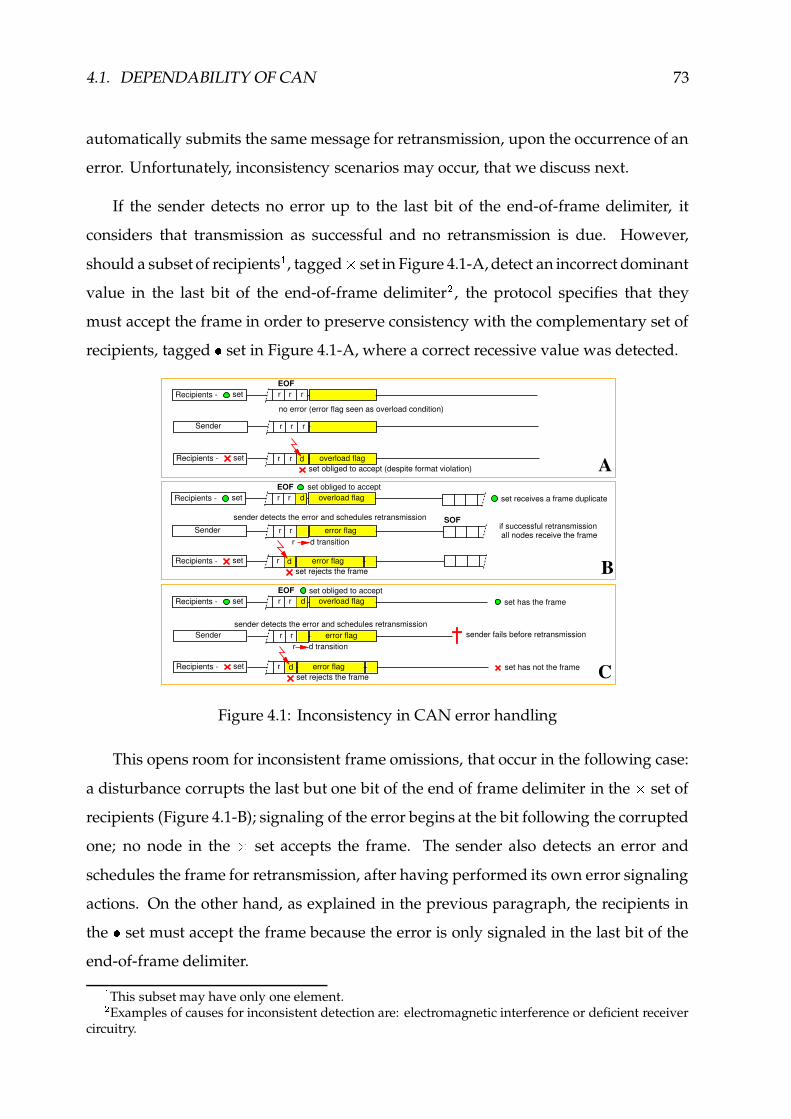
4.1. DEPENDABILITY OF CAN 73
automatically submits the same message for retransmission, upon the occurrence of an
error. Unfortunately, inconsistency scenarios may occur, that we discuss next.
If the sender detects no error up to the last bit of the end-of-frame delimiter, it
considers that transmission as successful and no retransmission is due. However,
should a subset of recipients�, tagged � set in Figure 4.1-A, detect an incorrect dominant
value in the last bit of the end-of-frame delimiter � , the protocol specifies that they
must accept the frame in order to preserve consistency with the complementary set of
recipients, tagged � set in Figure 4.1-A, where a correct recessive value was detected.
A
no error (error flag seen as overload condition)
setRecipients - r r dset obliged to accept (despite format violation)
overload flag
Sender r r r
setRecipients - EOFr r r
set obliged to accept
setRecipients - r dset rejects the frame
error flag
setRecipients - EOFr r d
sender detects the error and schedules retransmission
Sender r r error flag
B
set receives a frame duplicate
if successful retransmissionall nodes receive the frame
SOF
overload flag
setRecipients - EOFr r d
set obliged to accept
Sender r rsender detects the error and schedules retransmission
error flag
setRecipients - r dset rejects the frame
error flag C
sender fails before retransmission
set has the frame
set has not the frame
overload flag
r d transition
r d transition
Figure 4.1: Inconsistency in CAN error handling
This opens room for inconsistent frame omissions, that occur in the following case:
a disturbance corrupts the last but one bit of the end of frame delimiter in the � set of
recipients (Figure 4.1-B); signaling of the error begins at the bit following the corrupted
one; no node in the � set accepts the frame. The sender also detects an error and
schedules the frame for retransmission, after having performed its own error signaling
actions. On the other hand, as explained in the previous paragraph, the recipients in
the � set must accept the frame because the error is only signaled in the last bit of the
end-of-frame delimiter.�This subset may have only one element.�Examples of causes for inconsistent detection are: electromagnetic interference or deficient receiver
circuitry.

74 CHAPTER 4. DESIGNING DEPENDABLE CAN-BASED SYSTEMS
At this point, we have a problem: an exact duplicate of the message will be accepted
by the recipients in the � set of Figure 4.1-B, once retransmission is accomplished. This
happens because the CAN protocol automatic message retransmission does not modify
any frame field.
The problem gets worse if the sender fails after the first transmission and before
the retransmission. This last scenario is depicted in Figure 4.1-C, which shows that
inconsistent message omissions take place, affecting only the � set.
Probability of inconsistent errors
In order to establish the importance of inconsistent error scenarios we have eval-
uated the probability of their occurrence. Other types of errors are not addressed:
consistent errors are correctly processed by the CAN controllers; the residual proba-
bility of errors undetected by built-in CAN error-detection is negligible (Charzinski,
1994).
Node crash failures 0 GI�'�F��� ���+���������� � DInconsistent frame omissions 0 ��� J ������/ L(¡b¢%£(¤-£i� � � ���/ Inconsistent Message Duplicates 0Q¥(¦�§ � 0�� � J �{� 0XGI�'�F� LInconsistent Message Omissions 0 ¥(¦�¨�� 0 � � 0 GH�s�m�
Figure 4.2: Probabilities of inconsistent errors
The results of our evaluation are summarized in Figure 4.2. The CAN inconsis-
tent error probabilities are established as a function of a fundamental communication
channel parameter - the bit error rate (���/
). The model further considers an exponential
distribution for the time elapsed until a node crash ( © is the failure rate). The number
of correct bits before the occurrence of an error in a particular bit of a frame has a
geometric distribution, because the sender stops transmitting after the signaling of the
first error. In addition, it is assumed that the probability for the same bit error being
perceived simultaneously by all the nodes in the system is much lower than having

4.1. DEPENDABILITY OF CAN 75
it perceived only by a subset of the nodes. Thus, in this slightly simplified model the
probability of inconsistent frame omissions (0 � , in Figure 4.2) only accounts for a tem-
poral distribution of errors, occuring in the last but one bit of a frame with an overall
length of ª } �sDO� bits. The node crash failures are regarded as independent from frame
omissions. That means, the probability of occurrence of both events is given by the
product of the probabilities of occurrence of each individual event. Given a ~¬« period,
corresponding to the interval between the end of a transmission and the end of the
last retransmission, if the sender crashes within ~¬« after the first error, an inconsistent
message omission (IMO) occurs, with probability 0 ¥(¦�¨ (cf. Figure 4.2). Otherwise, the
sender retransmits the message, but this recovery action generates inconsistent message
duplicates (IMD), with probability 0 ¥(¦�§ .
Bit Error Rate Node failures IMD/hour IMO/hour(��/
) per hour ( © ) ~« �¯® �� �/�°� � �/�°� � R �3±<² � �/� � ³ �3´<² � ��Z� ��/�°� � R �3±<² � �/� � ³ �3´<² � ��Z� ��/�°� � �/�°� � R �3±µ � �/� � ³ �3´± � ��Z� ��/� � � R �3±µ � �/� � ³ �3´± � �� � �/�°� � �/�°� � R �3±°¶ � �/� � ³ �3´± � ��Z� �/�°� � R �3±°¶ � �/� � ³ �3´± � ��Z� "
Table 4.1: CAN inconsistent errors per hour
To finalize, we estimate the error rates in failures per hour, for several scenarios, in
the reference period of one hour � . The number of inconsistency incidents per hour goes
down proportionally with a decrement in the network data rate, overall offered load
or number of nodes. For a 32 node CAN fieldbus at 1 Mbps, a network overall load
of 90% and an average frame length of ª·} �sDO�Q� ����bits are assumed. Bit error rates are
presented (cf. Table 4.1) both for benign and aggressive environments, such as noisy
industries and automotive. Node crash failure rates are compliant with the values in
(Verıssimo & Kopetz, 1993; Kopetz & Grunsteidl, 1994). A latency of 5 ms is used as
�The average number of IMO incidents per hour is given by ¸I¹»º�¼H½¾b¿�Àr[2ÁÃÂ>Ä]W�Å Æa¼H½¾b¿�À , whereÆaM¼H½¾b¿�À is the number of frames transmitted in the reference period of one hour. In a similar way,¸H¹»Ç{¼I½�¾b¿ÀÈ[ÉÁ<Â(Ä{Ê�Å Æa¼H½¾b¿�À .

76 CHAPTER 4. DESIGNING DEPENDABLE CAN-BASED SYSTEMS
~¬« , a time interval roughly corresponding to the time required for the transmission of
one frame from each node in the network.
The results from this evaluation, presented in Table 4.1, should be compared with
the reference value of�� � " incidents per hour, the well-known safety number from the
aerospace industry (Powell, 1992), which is today also a goal for automotive applica-
tions (Kopetz, 1995). They are a clear indication that the influence of inconsistent errors
on system correctness cannot be neglected, at least for highly fault-tolerant applications
of CAN. A solution to this problem is required.
4.1.2 CAN Physical Level Fault-Tolerance
The CAN transmission medium is usually a two-wire differential line. The CAN
physical layer specified in (ISO, 1993) allows resilience against some of the transmission
medium failures illustrated in Figure 4.3, by switching from the normal two-wire
differential operation to a single-wire mode. After mode switch-over bus operation is
allowed to proceed, though with a reduced signal-to-noise ratio, in the presence of one
of the following failures:
– one-wire interruption (A or B failures, in Figure 4.3);
– one-wire short-circuit either to power (C or D) or ground (E or F);
– two-wire short-circuit (G).
CAN medium interfaces that automatically switch to single-wire operation upon
the detection of any of these failures and switch back to differential mode when re-
covered, are commercially available. Usually, such devices are intended for low-speed
applications (up to 125 kbps) with no more than 32 nodes (Philips, 1997b). One excep-
tion is the CAN interface described in (Alcatel, 1995).
The CAN bus line is usually terminated at both ends by its characteristic impedance
(CiA, 1992). Resilience to the failure of one termination (H failure, in Figure 4.3)
can be achieved simply by taking into account the extra time needed for bus signal
stabilization, when dimensioning the propagation time segment (ISO, 1993).

4.1. DEPENDABILITY OF CAN 77
In any case, no standardized mechanisms exist to provide resilience to the simulta-
neous interruption of both bus line wires (A and B failures, in Figure 4.3). Upon such a
failure, there may be subsets of the nodes which cannot communicate with each other.
Because damaging of all wires in a bus line may result from single incidents with the
network cabling, the probability of its occurrence is not negligible.
CAN_H
CAN_LGnd
A C E
HPower
Power
Node 1
CANInterface
Node n
Two-Wire Bus CableTermination TerminationGnd
B D FG
CANInterface
Figure 4.3: Resilience to medium failures in the ISO 11898 CAN standard
The provision of resilience to CAN physical partitioning is thus a requirement of
dependable real-time systems that is not fulfilled by the standard CAN specification.
A solution to this problem must resort to some form of network redundancy: media
redundancy allows to achieve high levels of availability in the presence of perma-
nent medium faults; full space-redundancy provides glitch-free operation and tight
timeliness guarantees.
4.1.3 Reliable Hard Real-Time Operation of CAN
The classical definition of network partitioning is normally attached to a notion of
physical disconnection: a network is partitioned when there are subsets of the nodes
which cannot communicate with each other � .However, even in a physically connected network, the occurrence of certain events
in its operation or of individual failures produce side-effects on the other nodes, which
are a subtle form of partitioning, virtual rather than physical. Standard LANs and
�The subsets may have a single element. When the network is completely down, all partitions have
a single element, since each node can communicate with no one.

78 CHAPTER 4. DESIGNING DEPENDABLE CAN-BASED SYSTEMS
fieldbuses have their own means of recovering from these situations, but since this
recovery process takes time, the network will exhibit periods where service is not
provided to some or all of the nodes (inaccessibility).
The impact of inaccessibility on real-time communication is the error it introduces
in the specification of timing bounds, such as deadlines, timeouts, etc. Most analyses of
message transmission delays or of network schedulability concentrate on the queuing
delays caused by the studied arrival patterns. They do so while modeling the network
as always functioning normally (Janetzky & Watson, 1986; Jain, 1990; Wang et al., 1992;
Zuberi & Shin, 1995; Tovar & Vasques, 1998a).
In consequence, bounds are established that will be violated upon the (even if rare)
occurrence of inaccessibility events. These faults, that temporarily prevent communi-
cation and whose effect is to increase the network access delay as seen by one or more
nodes, may lead to the failure of task or protocol timing assumptions and ultimately,
to the failure of the hard real-time system (Verıssimo, Rufino & Ming, 1997).
The duration of CAN inaccessibility periods, for the comprehensive set of error
scenarios that we address in Section 7.3.1, is represented in Figure 4.4. These may be
the cause of a severe time-domain misbehavior in systems where CAN operation in the
presence of network errors was not a design concern (e.g. (Tuominen & Virvalo, 1995;
Gil et al., 1997)).
0
500
1000
1500
2000
2500
3000
Bit Stuff CRC Form ACK Ovload React.Ovload
OvloadForm
Incons.Ovload
Burst M. Burst Deaf Rx Stuck Tx Stuck Rx Fail Tx Fail
Error Scenarios
CA
N 2
.0B
Inac
cess
ibili
ty (b
it-tim
es)
Min.Max.
Figure 4.4: Normalized CAN inaccessibility periods
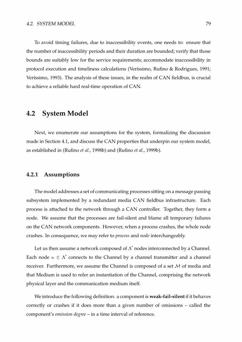
4.2. SYSTEM MODEL 79
To avoid timing failures, due to inaccessibility events, one needs to: ensure that
the number of inaccessibility periods and their duration are bounded; verify that those
bounds are suitably low for the service requirements; accommodate inaccessibility in
protocol execution and timeliness calculations (Verıssimo, Rufino & Rodrigues, 1991;
Verıssimo, 1993). The analysis of these issues, in the realm of CAN fieldbus, is crucial
to achieve a reliable hard real-time operation of CAN.
4.2 System Model
Next, we enumerate our assumptions for the system, formalizing the discussion
made in Section 4.1, and discuss the CAN properties that underpin our system model,
as established in (Rufino et al., 1998b) and (Rufino et al., 1999b).
4.2.1 Assumptions
The model addresses a set of communicating processes sitting on a message passing
subsystem implemented by a redundant media CAN fieldbus infrastructure. Each
process is attached to the network through a CAN controller. Together, they form a
node. We assume that the processes are fail-silent and blame all temporary failures
on the CAN network components. However, when a process crashes, the whole node
crashes. In consequence, we may refer to process and node interchangeably.
Let us then assume a network composed of Ë nodes interconnected by a Channel.
Each node )ÍÌÎË connects to the Channel by a channel transmitter and a channel
receiver. Furthermore, we assume the Channel is composed of a set Ï of media and
that Medium is used to refer an instantiation of the Channel, comprising the network
physical layer and the communication medium itself.
We introduce the following definition: a component is weak-fail-silent if it behaves
correctly or crashes if it does more than a given number of omissions – called the
component’s omission degree – in a time interval of reference.

80 CHAPTER 4. DESIGNING DEPENDABLE CAN-BASED SYSTEMS
In the context of CAN network components, an omission is an error that destroys
a data or remote frame. It does not matter how many individual bits get corrupted: a
single omission is accounted for each destroyed data/remote frame.
The CAN bus is viewed as a single-channel broadcast local network with the follow-
ing failure semantics for the network components (anything between two processes,
including network adapters and the physical layer path):
f individual components are weak-fail-silent with omission degree Ð�Ñ ;f failure bursts never affect more than ÐMÑ transmissions in a time interval of reference � ;f omission failures may be inconsistent (i.e., not observed by all recipients);
f there is no permanent failure of the Channel (e.g. the simultaneous partition of all media).
Establishing a bound for the omission degree ( ÒÔÓ �+Õ Ñ ) of individual components
provides a general method for the detection of failed components. If each omission is
detected and accounted for, the component fails once it exceeds the omission degree
bound. In particular, a Medium fails if it crashes (stuck-at or broken failures) or if it
exceeds ÒÔÓ .
The omission degree is also a general measure of the reliability of the CAN compo-
nents to transient errors: failure bursts affect at most Õ Ñ transmissions in a time interval
of reference. However, for the particular set Ï of media, we make the additional fault
assumptions:
f failures in different media are independent;
f permanent omission failures never affect more than Ör×ÙØ y media.
The weak-fail-silent assumption can be enforced at the CAN controller level by
the fault confinement mechanisms discussed in Section 4.1.1. This is important to
parameterize system and protocol operation. Furthermore, we assume that:
f in a time interval of reference, no more than Ð nodes/processes are affected by crash
failures.
�For instance, the duration of a broadcast round. Note that this assumption is concerned with the
total number of failures of possibly different components.
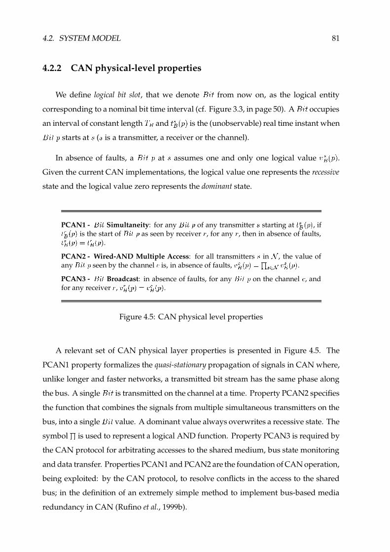
4.2. SYSTEM MODEL 81
4.2.2 CAN physical-level properties
We define logical bit slot, that we denote Ú�Û%« from now on, as the logical entity
corresponding to a nominal bit time interval (cf. Figure 3.3, in page 50). A Ú�Û8« occupies
an interval of constant length Ü·Ý and « BÝ JO0 L is the (unobservable) real time instant when
Ú�Û8«70 starts at
(
is a transmitter, a receiver or the channel).
In absence of faults, a Ú�Û8«�0 at
assumes one and only one logical value Þ BÝ JV0 L .Given the current CAN implementations, the logical value one represents the recessive
state and the logical value zero represents the dominant state.
PCAN1 - ß]à4á Simultaneity: for any ß�à4ánâ of any transmitter 6 starting at á BÝäã â�å , ifá uÝ ã â�å is the start of ß]àCá7â as seen by receiver æ , for any æ , then in absence of faults,á BÝ ã â�åèçéá uÝ ã â�å .PCAN2 - Wired-AND Multiple Access: for all transmitters 6 in ê , the value ofany ß�à4ánâ seen by the channel ë is, in absence of faults, ìZíÝ ã â�åèç�î B(ïIð ì BÝ ã â�å .PCAN3 - ß]à4á Broadcast: in absence of faults, for any ß]àCá�â on the channel ë , andfor any receiver æ , ì uÝ�ã â�åèç�ì íÝäã â�å .
Figure 4.5: CAN physical level properties
A relevant set of CAN physical layer properties is presented in Figure 4.5. The
PCAN1 property formalizes the quasi-stationary propagation of signals in CAN where,
unlike longer and faster networks, a transmitted bit stream has the same phase along
the bus. A single Ú�Û%« is transmitted on the channel at a time. Property PCAN2 specifies
the function that combines the signals from multiple simultaneous transmitters on the
bus, into a single Ú�Û8« value. A dominant value always overwrites a recessive state. The
symbol î is used to represent a logical AND function. Property PCAN3 is required by
the CAN protocol for arbitrating accesses to the shared medium, bus state monitoring
and data transfer. Properties PCAN1 and PCAN2 are the foundation of CAN operation,
being exploited: by the CAN protocol, to resolve conflicts in the access to the shared
bus; in the definition of an extremely simple method to implement bus-based media
redundancy in CAN (Rufino et al., 1999b).

82 CHAPTER 4. DESIGNING DEPENDABLE CAN-BASED SYSTEMS
4.2.3 CAN MAC-level properties
We can look at CAN as having a basic medium access control (MAC) sub-layer, that
behaves basically like a LAN MAC sub-layer – as do most other fieldbuses – and as
such, exhibits the same kind of properties that have been identified in previous works
on LANs. See for example (Verıssimo, 1993) for a description of abstract properties of
a LAN. Figure 4.6 enumerates a relevant set of CAN MAC-level properties.
MCAN1 - Broadcast: correct nodes receiving an uncorrupted frame transmission,receive the same frame.
MCAN2 - Error Detection: correct nodes detect any corruption done by the net-work in a locally received frame.
MCAN3 - Network Order: any two frames received at any two correct nodes, arereceived in the same order at both nodes.
MCAN4 - Local Full-Duplex: a correct node may receive, on request, local frametransmissions.
MCAN5 - Bounded Omission Degree: in a known time interval ñQuP} , omissionfailures may occur in at most ò transmissions.
MCAN6 - Bounded Inaccessibility: in a known time interval ñQu'} , the networkmay be inaccessible at most à times, with a total duration of at most ñ � , � .MCAN7 - Bounded Transmission Delay: any frame queued for transmission istransmitted on the network within a bounded delay of ñ D } x ñ � , � .MCAN8 - Tightness: correct nodes receiving an uncorrupted frame transmission,receive it at real time values that differ, at most, by a known small constant t�ó DF�õô@NiD .
Figure 4.6: CAN MAC-level properties
Properties MCAN1 and MCAN2 impose correctness in the value domain, in a
broadcast. Property MCAN1 formalizes that it is physically impossible for a node
to send conflicting information to different nodes, in the same broadcast (Babaoglu
& Drummond, 1985). Property MCAN2 derives directly from CAN built-in error
detection and signaling: a comprehensive set of mechanisms � allows the detection of
incorrect bit values in data/remote frames; the occurrence of an error is signaled by the
�Including protection through a CRC polynomial.

4.2. SYSTEM MODEL 83
issuing of an error frame; frames affected by errors are discarded, usually by the CAN
controller itself. Such kind of operation ensures that: frame errors are transformed in
omissions; with a very high probability, an error in the information encapsulated in a
data/remote frame is handled consistently by all correct nodes; the residual probability
of undetected frame errors is negligible (Charzinski, 1994).
Property MCAN5 maps the failure semantics introduced earlier onto the oper-
ational assumptions of CAN, being ��ö Õ Ñ . This property is crucial to implement
protocols yielding bounded termination times. A bounded omission degree is secured
by CAN fault confinement (cf. ÷ 4.1.1) and by media redundancy mechanisms.
Properties MCAN3 and MCAN4 are common in LANs and fieldbuses. The order
property (MCAN3) is imposed by the communication medium within a single network
segment and results directly from the serialization of frame transmissions on the shared
bus. Property MCAN4 specifies that the sender itself is also included in that ordering
property, as a recipient. Property MCAN4 is secured directly in some CAN controllers
(Philips, 1997a; Motorola, 1998). Otherwise, firmware algorithms and/or specialized
hardware mechanisms may be used to secure the property.
The behavior of CAN in the time domain is described by the remaining properties.
Property MCAN7 specifies a maximum frame transmission delay, which is Ü D } in the
absence of faults. The value of Ü D } includes the queuing, access and transmission delays.
It depends on message latency classes and offered load bounds (Tindell & Burns, 1994b;
Zuberi & Shin, 1997; Livani et al., 1998) and in general it may also include the extra
delays resulting from the queuing effects caused by the occurrence of inaccessibility
events. The bounded frame transmission delay also includes �� , � , a corrective term
which accounts for the worst-case duration of the inaccessibility glitches, given the
bounds specified by property MCAN6. The inaccessibility characteristics of CAN
depend on the network alone and can be predicted by the analysis of the CAN protocol
(Rufino & Verıssimo, 1995; Verıssimo, Rufino & Ming, 1997).
Finally, property MCAN8 defines the maximum interval between frame reception
instants in different nodes. The value of ~�ø DF�õô@NiD depends on the network propagation
delay variance, which in CAN is always a small fraction of the nominal network bit
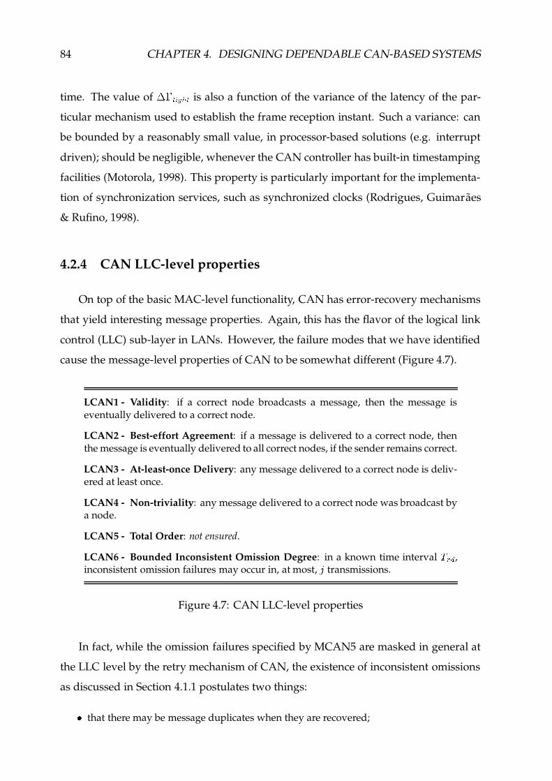
84 CHAPTER 4. DESIGNING DEPENDABLE CAN-BASED SYSTEMS
time. The value of ~�ø DF�õô@NiD is also a function of the variance of the latency of the par-
ticular mechanism used to establish the frame reception instant. Such a variance: can
be bounded by a reasonably small value, in processor-based solutions (e.g. interrupt
driven); should be negligible, whenever the CAN controller has built-in timestamping
facilities (Motorola, 1998). This property is particularly important for the implementa-
tion of synchronization services, such as synchronized clocks (Rodrigues, Guimaraes
& Rufino, 1998).
4.2.4 CAN LLC-level properties
On top of the basic MAC-level functionality, CAN has error-recovery mechanisms
that yield interesting message properties. Again, this has the flavor of the logical link
control (LLC) sub-layer in LANs. However, the failure modes that we have identified
cause the message-level properties of CAN to be somewhat different (Figure 4.7).
LCAN1 - Validity: if a correct node broadcasts a message, then the message iseventually delivered to a correct node.
LCAN2 - Best-effort Agreement: if a message is delivered to a correct node, thenthe message is eventually delivered to all correct nodes, if the sender remains correct.
LCAN3 - At-least-once Delivery: any message delivered to a correct node is deliv-ered at least once.
LCAN4 - Non-triviality: any message delivered to a correct node was broadcast bya node.
LCAN5 - Total Order: not ensured.
LCAN6 - Bounded Inconsistent Omission Degree: in a known time interval ñQu'} ,inconsistent omission failures may occur in, at most, ù transmissions.
Figure 4.7: CAN LLC-level properties
In fact, while the omission failures specified by MCAN5 are masked in general at
the LLC level by the retry mechanism of CAN, the existence of inconsistent omissions
as discussed in Section 4.1.1 postulates two things:
f that there may be message duplicates when they are recovered;

4.3. CAN STANDARD LAYER AND EXTENSION 85
f that some ù of the ò omissions will show at the LLC interface as inconsistent omissions.
Figure 4.7 enumerates the LLC-level properties of CAN. The first five properties
result from the frame retransmission scheme of CAN, in the presence of (inconsistent)
omissions. Property LCAN6 specifies the probability of inconsistent omission failuresú, where
úis normally several orders of magnitude smaller than � (cf. ÷ 4.1.1). Property
LCAN6 is extensively exploited in the design of reliable communication services.
4.3 CAN Standard Layer and Extension
The CAN standard layer is made from a CAN controller and the corresponding
software driver, that includes primitives for: request the transmission (.req) of data or
control messages � , supporting arbitration of requests by urgency level on both local and
global basis; confirm to the user a successful message transmission (.cnf), guaranteeing
that property LCAN1 is secured; indication of a message arrival (.ind).
The semantics of each particular primitive is summarized in Figure 4.8. Most of the
attributes are defined in the standard document (ISO, 1993) and have an appropriate
support from the CAN controller. However, a few exceptions exist: i) local arbitration
by urgency level may require specific management actions (Intel, 1995; Dallas, 1999);
ii) reception of own transmissions is not assured in all controllers (Intel, 1995; Dallas,
1999), so low-level engineering may be required; iii) the local execution environment
must process frame arrivals with a latency low enough to guarantee that no receive
buffer overrun incidents will ever occur .The information encapsulated in data/remote frames always include a message
control field. Data frames may also include message data. The message control field
consists of: a type reference, the sender identifier and a sequence number. The type
reference merges urgency and protocol control information.
�Control messages are encapsulated in remote frames.!This kind of omission failures have not been included in our model.

86 CHAPTER 4. DESIGNING DEPENDABLE CAN-BASED SYSTEMS
.req .cnf .ind
can-abortcan-data can-rtr
.req
CAN Layer
CAN Communication Channel
.req.cnf.ind.nty
CAN controller
Primitives Semantics summaryData Remote
can-data.req Only a node is allowed to transmit, at a time.can-rtr.req Several nodes may simultaneously transmit the same
remote frame.can-data.cnf can-rtr.cnf Signals the successful transmission of a frame.can-data.ind can-rtr.ind Signals the arrival of a data/remote frame, including
own transmissions.can-data.nty Extension to standard: signals the arrival of a data frame,
without delivering the message data.can-abort.req Aborts a frame transmission request. Has effect only on
pending requests.
Figure 4.8: CAN standard layer structure and interface
The set of primitives specified in Figure 4.8 includes a small extension to the stan-
dard interface: a notification primitive (.nty), signaling the arrival of a data frame (own
transmissions included). However, the message data field is not delivered. Only the
message control information is included in the notification.
4.4 System Architecture
The CAN fieldbus is nowadays a very important design component. A large set
of devices, intended for the implementation of the CAN standard layer, are available
in different configurations: stand alone CAN controllers (Intel, 1995; Philips, 1997a);
devices integrating, in a single chip, single/dual CAN controllers and an intelligent
processor infrastructure (Dallas, 1999; Siemens, 1995a; Motorola, 1998).
This represents a very strong argument in favor of using commercially available
CAN devices and drivers. Though the native CAN protocol exhibits a set of severe
dependability shortcomings, which we have identified in Section 4.1, its operation can
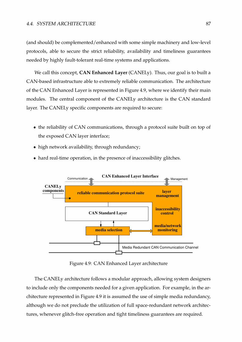
4.4. SYSTEM ARCHITECTURE 87
(and should) be complemented/enhanced with some simple machinery and low-level
protocols, able to secure the strict reliability, availability and timeliness guarantees
needed by highly fault-tolerant real-time systems and applications.
We call this concept, CAN Enhanced Layer (CANELy). Thus, our goal is to built a
CAN-based infrastructure able to extremely reliable communication. The architecture
of the CAN Enhanced Layer is represented in Figure 4.9, where we identify their main
modules. The central component of the CANELy architecture is the CAN standard
layer. The CANELy specific components are required to secure:
� the reliability of CAN communications, through a protocol suite built on top of
the exposed CAN layer interface;
� high network availability, through redundancy;
� hard real-time operation, in the presence of inaccessibility glitches.
CAN Standard Layer
CAN Enhanced Layer Interface
reliable communication protocol suite
media selection
layermanagement
inaccessibility control
media/network monitoring
Media Redundant CAN Communication Channel
CANELycomponents
Communication Management
Figure 4.9: CAN Enhanced Layer architecture
The CANELy architecture follows a modular approach, allowing system designers
to include only the components needed for a given application. For example, in the ar-
chitecture represented in Figure 4.9 it is assumed the use of simple media redundancy,
although we do not preclude the utilization of full space-redundant network architec-
tures, whenever glitch-free operation and tight timeliness guarantees are required.

88 CHAPTER 4. DESIGNING DEPENDABLE CAN-BASED SYSTEMS
The functional modules in the CANELy reliable communications protocol suite aim
to render an interface enhanced with a set of semantically rich services, such as group
communication, membership and failure detection, clock synchronization and support
to group management, useful to the implementation of distributed fault-tolerance
techniques (Rufino et al., 1999d).
Other modules in the CAN Enhanced Layer architecture are intended to support:
the control of CAN inaccessibility; media redundancy and network operation moni-
toring; configuration and layer management. The additional information provided by
these modules can be made available to upper layer entities, through a management in-
terface. For example, the CANELy layer management entities may issue a notification
that: a given Medium has failed; the network has been inaccessible for a given period
of time. Such kind of information may be extremely relevant, e.g. in management and
diagnose applications.
Execution platform
The CANELy software components can be installed on the same processing infras-
tructure than application processes, being executed at the operating system level: as
traditional device drivers, in general-purpose operating systems (e.g. Linux (Rubini,
1998)); in real-time multitasking executive environments (eCos, 2000; RTEMS, 2000b).
On the other hand, one may take advantage of the availability of specific hardware
platforms, such as those integrating in a single chip, single/dual CAN controllers and
intelligent processing infrastructures (Dallas, 1999; Siemens, 1995a; Motorola, 1998).
The use of platforms dedicated to the execution of CANELy software components
is extremely advantageous, in the sense that it allows to reduce the interference from
application level processing entities on the execution of CANELy protocols. This design
approach is also of fundamental importance to: prevent the occurrence of receive
overrun incidents, a kind of omission failures not included in our model; introduce,
with a little extra cost, a relevant set of additional functions, such as a highly flexible
low-level address filtering scheme (Rufino et al., 1998c).

4.4. SYSTEM ARCHITECTURE 89
Operating system support
Should a dedicated processing platform be used, the operating system support
needed at the application level is extremely simplified, being restricted to a simple
device driver interface (Rubini, 1998; eCos, 2000; RTEMS, 2000a).
The dedicated processing infrastructure may still benefit from operating system
services, through the use of: simple real-time multitasking executives, such as the
DCX-51 (DCX51, 1987) or û C/OS (Labrosse, 1992); operating systems compatible with
the OSEK specification (OSEK, 2000c), such as ERCOS (Poledna et al., 1996); simplified
versions of the eCos or RTEMS multitasking executives (eCos, 2000; RTEMS, 2000b).
Local support environment
To ensure a high portability of CANELy software components, the design of those
components assumes the availability of operating system independent services, such
as those provided by the Local Support Environment (LSE), described in (Fonseca et al.,
1990). Such kind of services can be mapped directly on the execution platform hardware
or preferably on top of the local executive.
A CAN-oriented local support environment should handle effectively: the manage-
ment of message buffers, taking into account urgency semantics; a comprehensive set of
local timer management and signaling functions, such as those specified in Figure 4.10.
LSE Timer Management
Primitive Parameters Description
lse start alarm.req t out timeout value starts an alarm service.
key user identifier (optional)
tid timer identifier (output)
lse cancel alarm.req key/tid user/timer identifier cancels the specified alarm.
lse alarm.nty key/tid user/timer identifier notifies that an alarm has expired.
Figure 4.10: Relevant timer functions in the local support environment

90 CHAPTER 4. DESIGNING DEPENDABLE CAN-BASED SYSTEMS
The timer management functions included in the local support environment
(Figure 4.10) should allow CANELy modules to: start a timer (lse start alarm.req),
given the wait period and an optional user level identifier; cancel an active timer
(lse cancel alarm.req), given the corresponding user or system-level identifiers; be
notified (lse alarm.nty), whenever a timer expires. The user-level identifier specifies
whether the timer is being used for the surveillance of local or remote interactions.
4.5 Summary
This chapter discusses the shortcomings of the native CAN protocol, with respect
to dependability related properties and formalizes such discussion in the definition of
a system model, which takes the properties of CAN into account.
The definition of a systemic model for a CAN-based system is extremely useful, in the
sense it shows the weaknesses of CAN with regard to dependability and provides the
grounds to handle those shortcomings effectively.
This chapter also discusses the structure and the interface of the CAN standard
layer and how such communication infrastructure can be complemented/enhanced
with a set of additional mechanisms, able to secure the provision of:
� reliable communication;
� high network availability;
� reliable hard real-time operation.
We call this concept and the corresponding network component, which may consist
of an intelligent processing infrastructure complemented with some simple machinery
and low-level protocol modules, CAN Enhanced Layer (CANELy).

Reliable Communication
The design of dependable distributed control systems may benefit to a great extent
from the availability of reliable communication services, such as those foreseen for
the CAN Enhanced Layer interface (group communication, membership and failure
detection, clock synchronization).
In fact, those services may be extremely relevant for an efficient implementation
of distributed fault-tolerance techniques useful in a variety of applications, including
those interacting with replicated input/output entities: not only do they give replicas a
uniform treatment, but they easily handle constructs specifically intended to interface
real devices, such as functional sets of sensors/actuators (Kopetz & Verıssimo, 1993).
Fieldbus technologies are networking infrastructures specifically designed and
widely used in sensing and actuating. However, the design and implementation of
fault-tolerant communication systems in the simple fieldbus environment presents
non-negligible problems, that we address in the context of CAN.
One key point with that regard concerns a widespread belief that CAN native
mechanisms provide reliable communication. Perhaps influenced by a certain lack
of accuracy in the standard CAN documentation, there have been published works
that assume CAN supports a (totally ordered) atomic broadcast service (Peraldi &
Decotignie, 1995; Poledna, 1995; Hilmer et al., 1997). The coverage of this assumption is
only acceptable under modest requirements on system reliability (Rufino et al., 1998b).
In Section 4.1.1, we have analyzed the reliability of CAN communications and
their weaknesses, explaining how network errors may lead to: inconsistent data frame
transfers; generation of data frame duplicates. Given their probability of occurrence,
91

92 CHAPTER 5. RELIABLE COMMUNICATION
that we have estimated (Rufino et al., 1998b) (cf. Table 4.1, page 75), the influence of
those errors cannot be ignored, for fault-tolerant systems and applications.
In this chapter, we use the results of (Rufino et al., 1998b) to: compare the properties
of CAN with a common definition of atomic broadcast, dismissing the misconception
that CAN supports a totally ordered message dissemination service ( ÷ 5.1); show how
a fault-tolerant broadcast primitive can be efficiently supported by a simple software
layer built on top of an exposed CAN controller interface ( ÷ 5.2); discuss how those
mechanisms can be used to support reliable group communication in CAN ( ÷ 5.3).
Secondly, since there are no standardized distributed membership and node failure
detection services in CAN, we address the problem in a comprehensive way, reasoning
about the different design options, discussing how those services can be supported by
software components above the CAN standard layer and analyzing protocol efficiency,
in terms of network bandwidth utilization and failure detection latency ( ÷ 5.4). In
addition, we shortly address how a fault-tolerant clock synchronization service can be
implemented in CAN ( ÷ 5.5).
Finally, in Section 5.6, we discuss the advantages of providing a specialized support
for the execution of the reliable communication protocols.
5.1 Atomic Broadcast Properties
The error-recovery mechanisms built within the CAN protocol yield interesting
message properties, which we have formalized in Figure 4.7, page 84. Such properties
have substantiated the claim that CAN exhibits atomic broadcast capability (Peraldi
& Decotignie, 1995; Poledna, 1995; Hilmer et al., 1997). However, let us analyze the
definition of such a broadcast, in order that we may understand why this is not so
under all circumstances. We use an adaptation of the definition of atomic broadcast
used by several authors (Hadzilacos & Toueg, 1993; Rodrigues & Verıssimo, 1992):
AB1 - Validity: if a correct node broadcasts a message, then the message is eventually
delivered to a correct node.
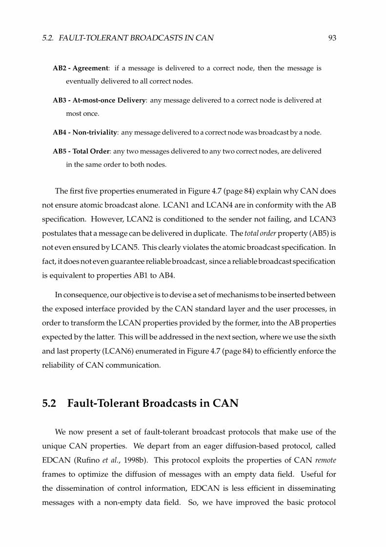
5.2. FAULT-TOLERANT BROADCASTS IN CAN 93
AB2 - Agreement: if a message is delivered to a correct node, then the message is
eventually delivered to all correct nodes.
AB3 - At-most-once Delivery: any message delivered to a correct node is delivered at
most once.
AB4 - Non-triviality: any message delivered to a correct node was broadcast by a node.
AB5 - Total Order: any two messages delivered to any two correct nodes, are delivered
in the same order to both nodes.
The first five properties enumerated in Figure 4.7 (page 84) explain why CAN does
not ensure atomic broadcast alone. LCAN1 and LCAN4 are in conformity with the AB
specification. However, LCAN2 is conditioned to the sender not failing, and LCAN3
postulates that a message can be delivered in duplicate. The total order property (AB5) is
not even ensured by LCAN5. This clearly violates the atomic broadcast specification. In
fact, it does not even guarantee reliable broadcast, since a reliable broadcast specification
is equivalent to properties AB1 to AB4.
In consequence, our objective is to devise a set of mechanisms to be inserted between
the exposed interface provided by the CAN standard layer and the user processes, in
order to transform the LCAN properties provided by the former, into the AB properties
expected by the latter. This will be addressed in the next section, where we use the sixth
and last property (LCAN6) enumerated in Figure 4.7 (page 84) to efficiently enforce the
reliability of CAN communication.
5.2 Fault-Tolerant Broadcasts in CAN
We now present a set of fault-tolerant broadcast protocols that make use of the
unique CAN properties. We depart from an eager diffusion-based protocol, called
EDCAN (Rufino et al., 1998b). This protocol exploits the properties of CAN remote
frames to optimize the diffusion of messages with an empty data field. Useful for
the dissemination of control information, EDCAN is less efficient in disseminating
messages with a non-empty data field. So, we have improved the basic protocol

94 CHAPTER 5. RELIABLE COMMUNICATION
to provide an unordered reliable broadcast primitive, called RELCAN, and a totally
ordered primitive, called TOTCAN. The protocol suite, which is illustrated in Figure 5.1,
executes on top of the CAN standard layer. Each protocol provides a request primitive
(used to invoke the protocol), a confirm primitive (used to inform the sender of protocol
local completion), and an indication primitive (used to deliver the message at the upper
layer interface).
CAN Standard Layer
EDCAN TOTCAN(totally ordered)
RELCAN(unordered)
Upper Layer Interface
Primitive ProtocolType Description EDCAN RELCAN TOTCAN
Request protocol invocation edcan.req relcan.req totcan.reqConfirm signaling of local completion edcan.cnf relcan.cnf totcan.cnfIndication upper layer message delivery edcan.ind relcan.ind totcan.ind
Figure 5.1: CAN fault-tolerant broadcast protocol suite
None of the protocols is based on the exchange of acknowledgments (Melliar-Smith
& Moser, 1989; Rodrigues & Verıssimo, 1992): such an approach is not an interesting
solution in CAN, because it consumes too much bandwidth (a scarce resource in CAN)
and makes no use of the built-in error detection properties.
5.2.1 Message Diffusion Protocol
The first protocol that we discuss is a diffusion-based protocol (Cristian, 1990;
Babaoglu & Drummond, 1985) with some optimizations to save channel bandwidth.
In this protocol, the recipients are responsible for retransmitting the message. Retrans-
missions are issued as soon as the original message is received; thus we have called this
protocol “Eager Diffusion”, or simply EDCAN. If enough nodes retransmit the mes-

5.2. FAULT-TOLERANT BROADCASTS IN CAN 95
sage, one of these nodes will be a non-faulty sender and CAN properties will ensure
the reliability of message delivery. The protocol is sketched in Figure 5.2. The protocol
is invoked by the upper layer providing two parameters: a unique message identifier
and an optional data field. The control information in the message identifier (mid)
includes the message type (type), the sender identifier (s), and a sequence number (sn).
Eager Diffusion-based Protocol (EDCAN)
Initializationi00 ndup(mid) := 0; // number of duplicates, kept for each message
Senders00 when edcan.req(mid
*type,s,sn
., mess) invoked at p do // mid, message identifier
s01 if mess = NULL thens02 can-rtr.req (mid);s03 elses04 can-data.req (mid, mess);s05 fi;s06 od;s07 when can-rtr.cnf(mid, mess:=NULL) confirmed at p or can-data.cnf(mid, mess) confirmed at p dos08 edcan.cnf (mid, mess);s09 od;
Recipientr00 when can-rtr.ind(mid, mess:=NULL) received at q or can-data.ind(mid, mess) received at q dor01 ndup(mid) := ndup(mid) + 1;r02 if ndup(mid) = 1 then // new messager03 edcan.ind (mid, mess);r04 if mess = NULL thenr05 can-rtr.req (mid); // clustered transmissionsr06 elser07 can-data.req (mid, mess);r08 fi;r09 else if ndup(mid) ü j then // ý , is the inconsistent omission degree boundr10 can-abort.req (mid);r11 fi;r12 fi;r13 od;
Figure 5.2: Eager diffusion-based protocol
The protocol works as follows. The sender requests the transmission of the message
to the CAN layer. For messages with data field the can-data primitive is used. For
messages with an empty data field, remote frames (can-rtr) are used. If the sender does
not fail the original message is delivered. To tolerate the failure of the original sender,
recipients deliver the first copy of the message and eagerly retransmit it.
For messages with a data field, retransmissions flow on the channel one at a time.
This may be too costly in terms of network load. The bounded inconsistent omission
degree property (LCAN6, Figure 4.7) is exploited to optimize network bandwidth
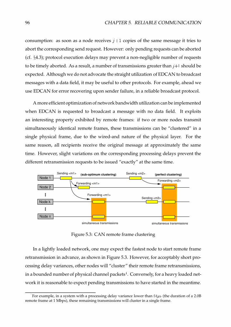
96 CHAPTER 5. RELIABLE COMMUNICATION
consumption: as soon as a node receivesú � � copies of the same message it tries to
abort the corresponding send request. However: only pending requests can be aborted
(cf. ÷ 4.3); protocol execution delays may prevent a non-negligible number of requests
to be timely aborted. As a result, a number of transmissions greater thanú � � should be
expected. Although we do not advocate the straight utilization of EDCAN to broadcast
messages with a data field, it may be useful to other protocols. For example, ahead we
use EDCAN for error recovering upon sender failure, in a reliable broadcast protocol.
A more efficient optimization of network bandwidth utilization can be implemented
when EDCAN is requested to broadcast a message with no data field. It exploits
an interesting property exhibited by remote frames: if two or more nodes transmit
simultaneously identical remote frames, these transmissions can be “clustered” in a
single physical frame, due to the wired-and nature of the physical layer. For the
same reason, all recipients receive the original message at approximately the same
time. However, slight variations on the corresponding processing delays prevent the
different retransmission requests to be issued “exactly” at the same time.
Node 2
Node n
Node 1Sending <m1>
Forwarding <m1>
simultaneous transmissions
(sub-optimum clustering)
Forwarding <m1>
Sending <m2>
Sending <m3>
Forwarding <m2>
(perfect clustering)
simultaneous transmissions
Node k
Figure 5.3: CAN remote frame clustering
In a lightly loaded network, one may expect the fastest node to start remote frame
retransmission in advance, as shown in Figure 5.3. However, for acceptably short pro-
cessing delay variances, other nodes will “cluster” their remote frame retransmissions,
in a bounded number of physical channel packets�. Conversely, for a heavy loaded net-
work it is reasonable to expect pending transmissions to have started in the meantime.
�For example, in a system with a processing delay variance lower than qbþHÿ�� (the duration of a 2.0B
remote frame at 1 Mbps), these remaining transmissions will cluster in a single frame.
5.2. FAULT-TOLERANT BROADCASTS IN CAN 97
The delays in network access, introduced by these transmissions, balance processing
delays variance and thus it is reasonable to expect all retransmissions following the
original dissemination of a remote frame to be clustered in a single physical layer
transmission. In any case, for a network with a moderate number of nodes, this allows
significant savings in network bandwidth. The upper layer should use remote frame
features as much as possible, relying on control frames that do not require a data field.
We discuss next an (unordered) reliable protocol and an atomic broadcast protocol that
use this approach.
5.2.2 Unordered Reliable Message Diffusion
Despite the optimizations we have introduced in the EDCAN protocol, the “Eager
Diffusion” approach is not cost-effective for broadcast of data messages due its high
bandwidth consumption. We now present a protocol that exploits the CAN validity
(LCAN1) and best-effort agreement (LCAN2) properties. The protocol, illustrated in
Figure 5.4, was called RELCAN as it provides an unordered reliable broadcast service
for data messages (Rufino et al., 1998b). Message retransmission by the protocol is only
due in the event of sender failure.
The protocol works as follows. The sender assigns a unique identifier to the data
message based on the node unique identifier (s) and on a local sequence number
(rel sn). The control information is carried within the message identifier (type is set
to R-DATA). Then, the sender calls an auxiliary “send-and-confirm” function, that
initiates a two-phase protocol.
In the first phase, send-and-confirm requests message transmission and awaits
the corresponding confirmation from the CAN controller. When this confirmation is
obtained, the sender is sure that the message has been received by all correct recipients
and initiates the second phase, disseminating a CONFIRM message. The reception
of the CONFIRM message indicates to all recipients that the associated data message
has been received and that no retransmission is required. Recipients deliver the first
copy of the message and prepare themselves to retransmit the message. However,
and in opposition to the eager protocol, retransmissions are not initiated immediately.

98 CHAPTER 5. RELIABLE COMMUNICATION
Instead, recipients wait first for the CONFIRM message. Only in the case the CONFIRM
message is not received, the receivers retransmit the message by invoking the EDCAN
protocol. The timer management functions used by the RELCAN protocol to implement
the alarm detecting the absence of CONFIRM messages are supported in the CAN local
support environment ( ÷ 4.4).
Unordered Reliable Message Diffusion Protocol (RELCAN)
Initializationi00 rel sn := 0; // local sequence numberi01 ndup(mid) := 0; // number of duplicates, kept for each messagei02 data(mid) := NULL; // buffer to store the data part of the message
send-and-confirm (auxiliary function)a00 send-and-confirm(mid
*R-DATA,s,sn
., mess) do
a01 can-data.req (mid*R-DATA,s,sn
., mess);
a02 when can-data.cnf(mid*R-DATA,s,sn
., mess) confirmed do
a03 can-rtr.req (mid*CONFIRM,s,sn
.);
a04 od;a05 od;
Senders00 when relcan.req(mess) invoked at p dos01 rel sn := rel sn + 1;s02 send-and-confirm (mid
*R-DATA,s:=p,rel sn
., mess);
s03 relcan.cnf (mess);s04 od;
Recipientr00 when can-data.ind(mid
*R-DATA,s,sn
., mess) received at q do
r01 ndup(mid) := ndup(mid) + 1;r02 lse start alarm.req (
�����������,mid); //
�����������, is the protocol timeout value
r03 if ndup(mid) = 1 then // new messager04 data(mid) := mess; // stores the received messager05 relcan.ind (mess);r06 fi;r07 od;r08 when can-rtr.ind(mid
*CONFIRM,s,sn
.) received at q do
r09 data(mid) := NULL; // clears the stored messager10 lse cancel alarm.req (mid);r11 od;r12 when lse alarm.nty(mid) received at q do // timer expiresr13 edcan.req (mid, data(mid));r14 od;r15 when edcan.ind(mid
*R-DATA,s,sn
., mess) received at q do
r16 ndup(mid) := ndup(mid) + 1;r17 if ndup(mid) = 1 then // new messager18 relcan.ind (mess);r19 fi;r20 od;
Figure 5.4: Unordered reliable broadcast protocol
At this stage, we have succeeded in making properties LCAN2 and LCAN3 equiv-
alent to properties AB2 and AB3. A slight modification to the RELCAN protocol allows
to yield multicast (group) addressing (cf. ÷ 5.3).

5.2. FAULT-TOLERANT BROADCASTS IN CAN 99
In the best case, the RELCAN protocol sends once the data message and once the
CONFIRM control message. In the event of sender failure, the performance of RELCAN
approaches the one observed in the EDCAN protocol.
5.2.3 Totally Ordered Message Diffusion
The previous protocol makes no effort to enforce a total order on message delivery.
In this section we discuss a new protocol, called TOTCAN, that uses the CAN network
order property (MCAN3, Figure 4.6 - page 82) to provide a totally ordered reliable
broadcast service (Rufino et al., 1998b). The basic idea of the protocol is to have the
messages delivered in the same order by which the encapsulating frames cross the
communication channel. If due to omissions, the same message is forced to cross the
channel more than once, only the order of the last retransmission (the successful one)
is considered (previous duplicates are discarded).
The protocol is illustrated in Figure 5.5. As RELCAN, the protocol is also a two-
phase protocol. In the first phase, called the dissemination phase, the sender tags the
data message with its node identifier (s) and a sequence number (tot sn). As before,
control information is carried in the identifier field (type is set to T-DATA). Then, the
sender broadcasts the message using the CAN interface. When the message is received,
instead of being immediately delivered to the application, it is held in a receive queue
marked as UNSTABLE. In the presence of inconsistent omissions, the same message
can be received more than once. To preserve network order, an UNSTABLE message
is moved to the tail of the queue each time a message duplicate is received. The data
message is never retransmitted by the recipients; should the sender fail before the
message becomes stable, it is simply discarded by all recipients.
The second phase is initiated as soon as the sender receives, from the local CAN
controller, a confirmation of success in the broadcast of the data message. At this point,
the sender can be sure that all correct recipients have received the message. To make
this information available to the recipients, the sender transmits an ACCEPT message.
Because the ACCEPT message must be reliably broadcast to all correct recipients, the
EDCAN protocol is used. Since the control field is able to hold all the information
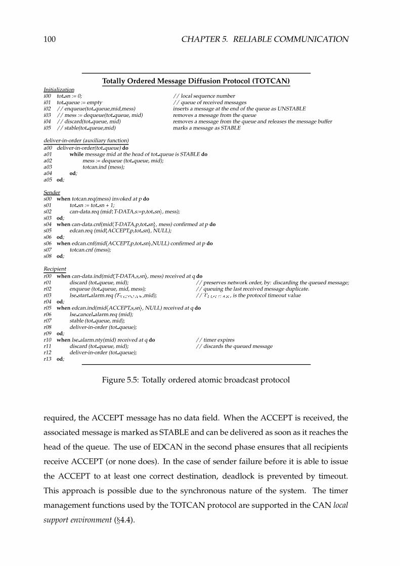
100 CHAPTER 5. RELIABLE COMMUNICATION
Totally Ordered Message Diffusion Protocol (TOTCAN)Initializationi00 tot sn := 0; // local sequence numberi01 tot queue := empty // queue of received messagesi02 // enqueue(tot queue,mid,mess) inserts a message at the end of the queue as UNSTABLEi03 // mess := dequeue(tot queue, mid) removes a message from the queuei04 // discard(tot queue, mid) removes a message from the queue and releases the message bufferi05 // stable(tot queue,mid) marks a message as STABLE
deliver-in-order (auxiliary function)a00 deliver-in-order(tot queue) doa01 while message mid at the head of tot queue is STABLE doa02 mess := dequeue (tot queue, mid);a03 totcan.ind (mess);a04 od;a05 od;
Senders00 when totcan.req(mess) invoked at p dos01 tot sn := tot sn + 1;s02 can-data.req (mid
*T-DATA,s:=p,tot sn
., mess);
s03 od;s04 when can-data.cnf(mid
*T-DATA,p,tot sn
., mess) confirmed at p do
s05 edcan.req (mid*ACCEPT,p,tot sn
., NULL);
s06 od;s06 when edcan.cnf(mid
*ACCEPT,p,tot sn
.,NULL) confirmed at p do
s07 totcan.cnf (mess);s08 od;
Recipientr00 when can-data.ind(mid
*T-DATA,s,sn
., mess) received at q do
r01 discard (tot queue, mid); // preserves network order, by: discarding the queued message;r02 enqueue (tot queue, mid, mess); // queuing the last received message duplicate.r03 lse start alarm.req (
�� ��� �����,mid); //
�� ��� �����, is the protocol timeout value
r04 od;r05 when edcan.ind(mid
*ACCEPT,s,sn
., NULL) received at q do
r06 lse cancel alarm.req (mid);r07 stable (tot queue, mid);r08 deliver-in-order (tot queue);r09 od;r10 when lse alarm.nty(mid) received at q do // timer expiresr11 discard (tot queue, mid); // discards the queued messager12 deliver-in-order (tot queue);r13 od;
Figure 5.5: Totally ordered atomic broadcast protocol
required, the ACCEPT message has no data field. When the ACCEPT is received, the
associated message is marked as STABLE and can be delivered as soon as it reaches the
head of the queue. The use of EDCAN in the second phase ensures that all recipients
receive ACCEPT (or none does). In the case of sender failure before it is able to issue
the ACCEPT to at least one correct destination, deadlock is prevented by timeout.
This approach is possible due to the synchronous nature of the system. The timer
management functions used by the TOTCAN protocol are supported in the CAN local
support environment ( ÷ 4.4).
5.2. FAULT-TOLERANT BROADCASTS IN CAN 101
In the best-case, TOTCAN requires the transmission of the data message plus
the bandwidth corresponding to a pair of remote frames, required by the EDCAN
protocol in the reliable broadcast of the ACCEPT message, if remote frame clustering
is perfect. When remote frame clustering is sub-optimum, an extra ACCEPT message
is transmitted (Figure 5.3).
At this point, we also have secured property LCAN5 (equivalent to AB5), finally
reaching our original goal of ensuring that CAN satisfies atomic broadcast. A variant
of the TOTCAN protocol allows to yield multicast addressing (cf. ÷ 5.3).
5.2.4 Bounded Sequence Numbers
For sake of clarity, we describe the protocols using unbounded sequence numbers.
The synchronous properties of the system allow to bound the sequence numbers: just
two bits in the CAN message identifier are required to ensure correct protocol operation.
In case of sender failure, the recipients are able to establish the message order and, if
required, retransmit the last message. The use of a sequence number based on a single
bit will not allow message ordering. This problem was identified and thoroughly
analyzed in (Feio & Lageira, 1998).
5.2.5 Related Work
The use of multicast/broadcast communications is not very common, in the so-
called fieldbus arena where most standards rely on OSI-like point-to-point communi-
cations. One of the few exceptions is the Controller Area Network (ISO, 1993; BOSCH,
1991). A set of CAN high layer protocols (SDS (SDS, 1996), J1939, OSEK (OSEK, 1997;
OSEK, 2000a)) specify the use of multicast/broadcast communications, but lack to pro-
vide a clear definition of the corresponding system fault-model. An accurate definition
of the system fault-model is essential to evaluate whether or not CAN weakness with
regard fault-tolerant broadcast have been taken into account. Perhaps mislead by some
lack of accuracy in CAN standards, some researchers neglect those aspects and claim

102 CHAPTER 5. RELIABLE COMMUNICATION
that CAN supports (totally ordered) atomic broadcasts (Peraldi & Decotignie, 1995;
Poledna, 1995; Hilmer et al., 1997).
An alternative solution to such a problem, to be implemented as an extension to the
CAN protocol by an additional hardware mechanism (SHARE), is described in (Kaiser
& Livani, 1999). Such mechanism detects the conditions which may lead to a possible
inconsistent message omission failure and provide message retransmission. An addi-
tional protocol provides a deadline-based ordering of hard real-time messages. The
drawbacks of this solution are: the need for specialized hardware; a possible violation
of the standard CAN specification, since more than one node may be simultaneously
transmitting the same data frame.
5.3 Group Communication in CAN
The fault-tolerant broadcast protocols discussed in Section 5.2 provide the grounds
to built a versatile group communication protocol suite, offering different qualities of
service in terms of ordering, agreement and synchronism properties.
The architecture of a CAN-based group communication protocol suite is depicted
in Figure 5.6. The top layer of the CAN-based group communication protocol suite
actually defines the service properties. For example, the R-CAN and the T-CAN pro-
tocols of Figure 5.6 are, respectively, the multicast variants of the reliable (RELCAN)
and totally ordered (TOTCAN) fault-tolerant broadcast protocols of Section 5.2. How-
ever, a comprehensive combination of different ordering, agreement and synchronism
properties are possible. For example, the L-CAN protocol described in (Rufino et al.,
1997), maintains the order and agreement properties of the R-CAN/RELCAN protocol
but trades a higher message delivery bound with a lower utilization of CAN network
bandwidth.
A set of other companion protocols are integrated in the architecture of the CAN-
based group communication protocol suite. For example: the EDCAN protocol, dis-
cussed in Section 5.2.1, has been integrated in the protocol suite to assist other protocols
in the reliable dissemination of control information. This includes: message retrans-

5.3. GROUP COMMUNICATION IN CAN 103
CAN Standard Layer
EDCAN
G-CAN(Group Addressing and Filtering)
F-CAN
R-CAN L-CAN T-CAN
Upper Layer Interface
Figure 5.6: CAN-based group communication protocol suite
mission, which may be required in the event of sender failure; pure control messages,
such as the T-ACCEPT and/or the R-CONFIRM control signals issued by the T-CAN
and R-CAN protocols, respectively.
Two other auxiliary protocols, G-CAN and F-CAN, complete the architecture of the
CAN-based group communication layer (Rufino et al., 1997; Rufino et al., 1998a).
The G-CAN protocol is intended to provide efficient group addressing and filtering
functions, restricting protocol processing in higher layers to the traffic actually ad-
dressed to the node. The group addressing information is included in the CAN frame
identifier, as specified in Appendix C.
The G-CAN protocol uses the group address field (cf. Figure C.1, page 241), together
with a list of locally active groups, to decide whether or not each message should
be delivered to the top layer protocols for processing. A message addressed to a
group which is not active in the node is simply discarded (message filtering). This
message filtering scheme is highly flexible, in the sense it does not depend of any
specific hardware mechanism. Protocol-dependent (e.g. group/broadcast) addressing
schemes can be easily implemented (Rufino et al., 1998c; Monteiro & Pedrosa, 1998).
Message filtering allows valuable savings of node processing resources, which are often
very scarce in the simple fieldbus infrastructures where CAN interfaces are included.

104 CHAPTER 5. RELIABLE COMMUNICATION
In addition, the G-CAN protocol includes a set of mechanisms helpful to: de-
tect/remove message duplicates, when the delivery of all message copies is not required
by the top layer group communication protocol; low-level generation of protocol con-
trol messages.
The F-CAN is the message fragmentation and reassembly protocol. The F-CAN
protocol exploits the MCAN3 (network order) and LCAN2 (best-effort agreement)
properties to support an efficient message fragmentation scheme that does not need
to use sequence numbers for fragment ordering. To save network bandwidth, each
fragment of the message (but the last), is simply disseminated using CAN standard
interface, with message type set to F-CAN (cf. Figure C.1, page 241). The last fragment,
disseminated with a message type corresponding to the requested quality of service (i.e.
set to R-CAN, L-CAN or T-CAN) establishes the message ordering, agreement and
synchronism properties.
An early prototype of a CAN-based group communication protocol suite has
been implemented and evaluated using the MIT LCS Advanced Network Architec-
ture group’s network simulator NETSIM (Heybey, 1990). A thorough description of
such a work is provided in (Feio & Lageira, 1998).
5.4 Failure Detection and Membership in CAN
A membership service is intended to provide, at any given time, consistent in-
formation about the state of a collection of participants. Though “participant” may
generically refer either to a process in a group of processes or to a site/node (processor)
in a distributed system, this section is specifically concerned with the provision of site
membership services in CAN-based systems.
The availability of a site membership service is extremely relevant to CAN reliable
communication, in the sense that: it may be a valuable auxiliary for process group
membership management; it may be used to simplify the design of other CAN-based
protocols (e.g. group communication, clock synchronization); it may be of great utility
for the implementation of very efficient protocol-related timer management functions.

5.4. FAILURE DETECTION AND MEMBERSHIP IN CAN 105
FailureDetection
Membership
CAN Standard Layer
Upper Layer Interface
Invocation Primitives (msh-can.req)
Description Parameters
Join 6 site/node identifier
Leave 6 site/node identifier
Get Membership View� B current set of active sites/nodes
Notification Primitives (msh-can.nty)
Description Parameters
Membership Change� B set of active sites/nodes� B set of failed nodes
Figure 5.7: CAN node failure detection and site membership protocol suite
The architecture of a failure detection/membership protocol suite, supported by
a software layer built on top of an exposed CAN controller interface, is depicted in
Figure 5.7. Upper layer protocol entities may request the local node to: join/leave the
set of active nodes; obtain the current site/node membership view. A notification of a
change in the composition of the set of currently active nodes is due whenever a node
joins/leaves the service or upon the detection of a node crash failure.
Let us assume a network composed of Ë nodes. We use � DB J() L to denote the site
membership view at node )ÉÌ Ë , after the « DON execution of the membership protocol.
Naturally, � DB J>) L�� Ë . For simplicity of exposition, we omit: the superscript identifying
the protocol round, when it refers to the last protocol execution; the variable identifying
the node, when it refers to the membership view agreed by all correct nodes.
Thus, the fundamental problem to be solved with regard to the provision of a
site/node membership service in CAN concerns the ability of correct nodes to reach
agreement on the � B set, within a bounded and known time. In essence, this is equiva-

106 CHAPTER 5. RELIABLE COMMUNICATION
lent to a consensus problem (Hadzilacos & Toueg, 1993).
The synchronous properties of the system allow to secure bounded protocol ter-
mination times. However, since CAN does not provide agreement guarantees in all
circumstances (cf. LCAN2, in Figure 4.7), such an attribute must be secured above
the CAN layer. This concerns mechanisms intended to (consistently) handle both
join/leave events and node crash failures.
5.4.1 Enforcing Agreement
A fundamental set of low-level agreement enforcement techniques, extremely rele-
vant to the design of failure detection and membership services in CAN, was identified
in (Rufino, 1998). In this section, we shortly discuss how such mechanisms can be
implemented as software modules (micro-protocols) built on top of an exposed CAN
controller interface. Further details can be found in (Rufino, 1998).
RECEPTION HISTORY BROADCAST
The first protocol that we address simply uses the CAN standard primitives to
request the broadcast of a special activity signal, called reception history vector (RHV).
Therefore, we dubbed this method Reception History Broadcast (RHB). The RHB protocol
is executed cyclicly, with a period given by �� . A given protocol round is started upon
the occurrence of the first of the following events: a local timer with a duration equal
to �� expires; an RHV signal is received from the network. Each active node performs
then the following actions:
f broadcast the reception history vector (RHV) built locally during the previous round;
f built the RHV to be broadcast in the next protocol round. The bit corresponding to a given
node in the RHV is marked active if an RHV signal is received from that node during the
current protocol round or marked inactive, otherwise;
f insert the data field of an RHV signal received from a given node into the corresponding
column of a local reception history matrix (RHM). Should no RHV signal be received within
a given time bound (cf. MCAN7, Figure 4.6), that node is considered failed.

5.4. FAILURE DETECTION AND MEMBERSHIP IN CAN 107
Given that the agreement property offered by CAN (cf. LCAN2, best-effort agree-
ment, in Figure 4.7 - page 84) is conditioned to the sender not failing, additional
mechanisms external to the RHB protocol are needed, in order to: analyze the status
of the local RHM; decide whether a node should be included in the site membership
view, � B J>) L , because it is fully integrated or should be withdrawn from ��B J>) L , because
it has failed or it has been turned off.
The RHB method is inspired by well-known techniques, used in other systems
(Kopetz et al., 1989; Kim et al., 1992). The application to CAN of the RHB method exhibits
several problems, that we discuss in (Rufino, 1998): a potentially high utilization of
network bandwidth, since the length of an RHV signal may be equal to the maximum
length of a CAN data frame; non-negligible overheads in the processing of the different
RHV signals.
Furthermore, the RHB companion protocols required for the analysis of RHM
exhibit even more severe drawbacks: a significant increase in complexity, if the incon-
sistent omission degree boundú�� �
(LCAN6, Figure 4.7); a worst-case latency in the
order of twice the cycle period, for the notification of a change in the membership view;
a potential lack of consistency in the provision of membership change notifications, in
the presence of simultaneous join and node failure events.
Therefore, we do not recommend the use of this method. It has been presented
only for completeness.
LIFE-SIGN BROADCAST
A first measure to reduce the network bandwidth consumed by the RHB protocol
replaces the RHV transmissions by the broadcast of simple life-sign messages. This
method was dubbed Life-Sign Broadcast (LSB) and given that all the relevant protocol
information (message type and node identifier) can be included in the control field of
the life-sign messages, these can be encapsulated in CAN remote frames, with no data
field. The LSB protocol is specified in Figure 5.8.

108 CHAPTER 5. RELIABLE COMMUNICATION
The execution of a LSB protocol round is started in a fully integrated node � either
when the node locally issues a request primitive or upon the reception of a life-sign
message from a remote node. In both cases, each active node requests the broadcast of
its own life-sign message and, during a given period, awaits the reception of life-sign
indications from other nodes.
Life-Sign Broadcast (LSB)
Initializationi00 � �����
:= � ; // Reception History Vectori01 tid := NULL; // tid, timer identifier
Senders00 when lsb-can.req() invoked at p dos01 if tid = NULL thens02 tid := lse start alarm.req (
���� �,p); // local timer.
���� �, is the worst-case protocol termination time
s03 can-rtr.req(mid*LSB,p
.); // life-sign transmit request
s04 fi;s05 od;
Recipientr00 when can-rtr.ind(mid
*LSB,s
.) received at q do
r01 if tid = NULL thenr02 tid := lse start alarm.req (
���� �,q); // local timer
r03 can-rtr.req(mid*LSB,q
.); // local life-sign transmit request
r04 fi;r05 � �����
:= � ���!�#"%$mid
*s.'&
; // includes node s in the � �����set
r06 od;r07 when lse alarm.nty(tid) received at q do // timer expiresr08 lsb-can.nty( � �����
); // upper layer notificationr09 tid := NULL;r10 � �����
:= � ;r11 od;
Figure 5.8: Life-sign broadcast micro-protocol
Each time a life-sign message is received, the sender node identifier (s) is included
in a reception history vector, �%(*),+ , as specified in Figure 5.8. If no life-sign message
is received from a node, its identifier is not included in the �-(*),+ set and such a node
is considered inactive � . When the waiting period ends, the LSB protocol notifies the
upper layer entities � of the current set of active nodes.
To prevent non integrated nodes to induce ill-timed executions of the LSB pro-
tocol, leading to the delivery of incorrect �.(*),+ values, those nodes are forced to a
�Meaning, the node has executed with success a set of protocol initialization actions (Rufino, 1998).�Possible causes of node inactivity are: the occurrence of a node crash failure; node switch off.�I.e., the node failure detection and/or the site membership protocol entities.

5.4. FAILURE DETECTION AND MEMBERSHIP IN CAN 109
wait/synchronization period (during a protocol initialization phase not specified in
Figure 5.8), before they are allowed to issue life-sign broadcasts.
The LSB protocol does not guarantee the consistency of the �-(*),+ sets delivered at
the different nodes, when the broadcast of a life-sign message is affected by an incon-
sistent omission error and the sender fails before completing the life-sign transmission.
This happens because CAN native mechanisms do not ensure message delivery to
all correct nodes in those circumstances. As a consequence, the LSB protocol cannot
provide the guarantee that a change in the composition of the �-(*),+ set is consistently
detected by all correct nodes within the same protocol round.
Nevertheless, the LSB protocol is extremely useful for node failure detection, in
the sense that: it allows each node to explicitly signal its active status using only a
small amount of network bandwidth (a scarce resource in CAN); it ensures that node
crash failures are always detected, at least by a subset of the correct nodes � , even if the
node failure is preceded by an inconsistent dissemination of the corresponding life-sign
message. Other mechanisms, external to the LSB protocol, can then be used to enforce
the consistency of node failure notifications.
RESTRICTED LIFE-SIGN BROADCAST
An optimized variant of the LSB protocol, which we have dubbed Restricted Life-
sign Broadcast (RLB), is discussed next. The RLB protocol favors a low utilization of
CAN bandwidth provided that only a subset of the nodes need to explicitly issue life-
sign messages; other nodes may signal their active state implicitly, for example while
transmitting normal traffic (Rufino et al., 1998a).
The RLB protocol (specified in Figure 5.9) is extremely simple: upon local protocol
invocation, e.g. by upper layer failure detection entities, a life-sign transmit request is
issued, using the standard CAN layer interface; when a life-sign is received from the
network, the corresponding notification is delivered to the upper layer entities.
�This subset may have only one element.
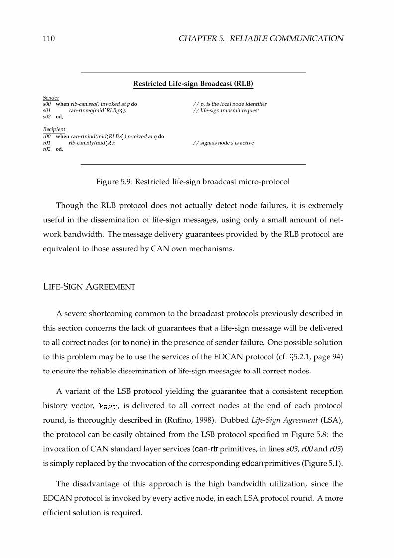
110 CHAPTER 5. RELIABLE COMMUNICATION
Restricted Life-sign Broadcast (RLB)
Senders00 when rlb-can.req() invoked at p do // p, is the local node identifiers01 can-rtr.req(mid
*RLB,p
.); // life-sign transmit request
s02 od;
Recipientr00 when can-rtr.ind(mid
*RLB,s
.) received at q do
r01 rlb-can.nty(mid*s.); // signals node s is active
r02 od;
Figure 5.9: Restricted life-sign broadcast micro-protocol
Though the RLB protocol does not actually detect node failures, it is extremely
useful in the dissemination of life-sign messages, using only a small amount of net-
work bandwidth. The message delivery guarantees provided by the RLB protocol are
equivalent to those assured by CAN own mechanisms.
LIFE-SIGN AGREEMENT
A severe shortcoming common to the broadcast protocols previously described in
this section concerns the lack of guarantees that a life-sign message will be delivered
to all correct nodes (or to none) in the presence of sender failure. One possible solution
to this problem may be to use the services of the EDCAN protocol (cf. ÷ 5.2.1, page 94)
to ensure the reliable dissemination of life-sign messages to all correct nodes.
A variant of the LSB protocol yielding the guarantee that a consistent reception
history vector, �/(0),+ , is delivered to all correct nodes at the end of each protocol
round, is thoroughly described in (Rufino, 1998). Dubbed Life-Sign Agreement (LSA),
the protocol can be easily obtained from the LSB protocol specified in Figure 5.8: the
invocation of CAN standard layer services (can-rtr primitives, in lines s03, r00 and r03)
is simply replaced by the invocation of the corresponding edcan primitives (Figure 5.1).
The disadvantage of this approach is the high bandwidth utilization, since the
EDCAN protocol is invoked by every active node, in each LSA protocol round. A more
efficient solution is required.

5.4. FAILURE DETECTION AND MEMBERSHIP IN CAN 111
FAILURE DETECTION AGREEMENT
The strategy chosen to reduce the network bandwidth used by the LSA protocol
is based on the observation that: node crash failures are relatively rare events (cf.
Table 4.1, in page 75); it is reasonable to assume that, in a period of reference, no more
than a given number of nodes, Õ , may fail. This opens room for the design of very
efficient protocols, in terms of network bandwidth utilization.
In the event of sender failure, the dissemination of life-sign messages by simple
broadcast protocols, such as the RLB protocol, may be inconsistent. Additional mecha-
nisms are needed to secure that upper layer entities are consistently notified of the lack
of life-sign messages, which constitutes a signal of a node crash failure.
Failure Detection Agreement (FDA)
Initializationi00 fs ndup(mid) := 0; // number of failure-sign duplicatesi01 fs nreq(mid) := 0; // number of failure-sign transmit requests
Senders00 when fda-can.req(s 1 ) invoked at p do // s 1 , is the failed node identifiers01 fs nreq(mid) := fs nreq(mid) + 1;s02 if fs nreq(mid) = 1 thens03 can-rtr.req(mid
*FDA,s 1 . ); // failure-sign transmit request
s04 fi;s05 od;
Recipientr00 when can-rtr.ind(mid
*FDA,s 1 . ) received at q do
r01 fs ndup(mid) := fs ndup(mid) + 1;r02 if fs ndup(mid) = 1 thenr03 fda-can.nty(mid
*s 1 . ); // notifies node s 1 has failed
r04 fs nreq(mid) := fs nreq(mid) + 1;r05 if fs nreq(mid) = 1 thenr06 can-rtr.req(mid
*FDA,s 1 . ); // failure-sign transmit request
r07 fi;r08 fi;r09 od;
Figure 5.10: Failure detection agreement micro-protocol
The Failure Detection Agreement (FDA) protocol, specified in Figure 5.10, is inspired
by the “Eager Diffusion” protocol ( ÷ 5.2.1) and aims to secure the reliable broadcast of
a failure-sign message. The identifier of the failed node (s G ) is specified, e.g. by upper
layer failure detection entities, when the protocol is invoked. The failed node identifier
and a message type indication can be included in the control field of a CAN frame,

112 CHAPTER 5. RELIABLE COMMUNICATION
meaning that remote frames may be used.
The FDA protocol works as follows: when invoked, the sender issues a single
request to the CAN layer for the transmission of a failure-sign message; the recipients,
deliver the first copy of the failure-sign message and in the absence of an equivalent
transmit request, invoke the CAN layer for failure-sign retransmission.
RECEPTION HISTORY AGREEMENT
Having described a set of micro-protocols useful to the signaling of node crash
failures, we address next how to consistently handle node join/leave events. Though
a variant of the LSA protocol could be used to manage individual occurrences of those
events, such a solution would be clearly inefficient in the presence of a massive number
of join/leave requests, due to a very high utilization of network bandwidth. The
Reception History Agreement (RHA) protocol, specified in Figure 5.11, aims the efficient
handling of multiple join/leave requests, using a small amount of network bandwidth.
The RHA protocol works as follows: each node in the site membership view
proposes its own value for a reception history vector (RHV); protocol execution ensures
that all correct nodes agree on the value of RHV to be delivered to upper layer entities.
We assume that the RHA protocol shares with upper layer entities the following
local variables: � B , the site membership view; � ý , the set of nodes in a joining process;� � , the set of nodes requesting to be withdrawn from the site membership view.
For a node included in the site membership view, the execution of the RHA protocol
starts: upon a request from upper layer entities; after the reception of an RHV signal
from a remote peer entity. In any case, the protocol establishes an initial value for the
reception history vector, based on the values of ��B , � ý and � � , and requests the broadcast
of the corresponding RHV signal (a message containing the value obtained for � (*)-+ ).
Should the initial value of �%(*)-+ be the same for all the nodes included in the site
membership view � , the RHA protocol simply ensures the reliable broadcast of the RHV
�Meaning: 2�3 and 2h have identical values for any node �-452�^ .
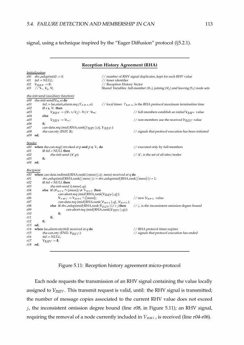
5.4. FAILURE DETECTION AND MEMBERSHIP IN CAN 113
signal, using a technique inspired by the “Eager Diffusion” protocol ( ÷ 5.2.1).
Reception History Agreement (RHA)
Initializationi00 rhv ndup(mid) := 0; // number of RHV signal duplicates, kept for each RHV valuei01 tid := NULL; // timer identifieri02 � �����
:= � ; // Reception History Vectori03 // ��6 , �87 , ��9 Shared Variables: full-member ( ��6 ), joining ( �:7 ) and leaving ( �;9 ) node sets
rha-init-send (auxiliary function)a00 rha-init-send( �;< ,s) doa01 tid := lse start alarm.req (
�����0�,s); // local timer.
�;���*�, is the RHA protocol maximum termination time
a02 if s ï ��6 thena03 � �����
:= (( ��6 " �:7 ) - �;9 ) =>� < ; // full-members establish an initial � �����value
a04 elsea05 � �����
:= � < ; // non-members use the received � �����value
a06 fi;a07 can-data.req (mid
*RHA,rank
* � ���!� . ,s . , � ���!� );a08 rha-can.nty (INIT, � ); // signals that protocol execution has been initiateda09 od;
Senders00 when rha-can.req() invoked at p and p ï ��6 do // executed only by full-memberss01 if tid = NULL thens02 rha-init-send ( ð ,p); // ð , is the set of all sites/nodess03 fi;s04 od;
Recipientr00 when can-data.ind(mid
*RHA,rank
* $mess
&'.,s., mess) received at q do
r01 rhv ndup(mid*RHA,rank
* $mess
&'.) := rhv ndup(mid
*RHA,rank
* $mess
&s.) + 1;
r02 if tid = NULL thenr03 rha-init-send (
$mess
&,q);
r04 else if ( � ���!� = $mess
&) ?@ � �����
thenr05 can-abort.req (mid
*RHA,rank
* � ����� .,q.);
r06 � �����:= � ���!� = $
mess&; // new � �����
valuer07 can-data.req (mid
*RHA,rank
* � ����� .,q., � ���!� );
r08 else if rhv ndup(mid*RHA,rank
* � ���!� .V. ) ü j then // ý , is the inconsistent omission degree boundr09 can-abort.req (mid
*RHA,rank
* � ����� .,q.);
r10 fi;r11 fi;r12 fi;r13 od;r14 when lse alarm.nty(tid) received at q do // RHA protocol timer expiresr15 rha-can.nty (END, � �����
); // signals that protocol execution has endedr16 tid := NULL;r17 � �����
:= � ;r18 od;
Figure 5.11: Reception history agreement micro-protocol
Each node requests the transmission of an RHV signal containing the value locally
assigned to �/(0),+ . This transmit request is valid, until: the RHV signal is transmitted;
the number of message copies associated to the current RHV value does not exceedú, the inconsistent omission degree bound (line r08, in Figure 5.11); an RHV signal,
requiring the removal of a node currently included in �>(0),+ , is received (line r04-r06).

114 CHAPTER 5. RELIABLE COMMUNICATION
The possible issuing of inconsistent �.(*),+ values by some nodes in the � B set is a
consequence of the occurrence of inconsistent omission failures during the transmission
of node join/leave requests, that lead to inconsistent values for � ý and/or � � . Upon the
processing of the remote RHV signal, any node not included in both RHV sets (local
and remote) is removed from the current � (*),+ value and the broadcast of the new� (*),+ value is requested (line r07). The number of rounds of the RHA protocol that
need to be executed to reach consensus on the value of � (*),+ to be delivered to upper
layer entities is bounded and can be known (cf. Appendix D.1).
Given that nodes in a joining process may not have a valid �pB value, such nodes are
not allowed to start the RHA protocol in isolation (line s00, of Figure 5.11). However,
those nodes are obliged to: initiate the execution of the RHA protocol as soon as they
receive an RHV signal from another node; use the contents of the RHV signal as the
initial value of �/(0),+ (line a05); participate in the dissemination of the different �-(*)-+values; deliver to the upper layer entities the final �-(*)-+ value.
The ranking function included in the RHA protocol (e.g. lines a07 and r07, in
Figure 5.11) aims to give the highest transmission priority to the RHV signals with the
highest number of inactive nodes, in order to reduce the overall number of messages
needed to execute the protocol.
Protocol comparison
This section compares the network bandwidth consumed by the different agreement
enforcement micro-protocols, in a period of reference. A detailed analysis of CAN
bandwidth utilization by each agreement micro-protocol is provided in Appendix D.1.
The results from that analysis, representing the utilization of CAN bandwidth per each
active node, are summarized in Figure 5.12.
An industrial setting of reference, consisting of a 32 node CAN fieldbus, is assumed.
When relevant (cf. Appendix D.1), the CAN related parameters are: inconsistent
omission degree bound,ú � �
; maximum number of message transmit requests not
aborted due to protocol processing delays, A � �. Harsh operating conditions are

5.4. FAILURE DETECTION AND MEMBERSHIP IN CAN 115
0
50
100
150
200
250
300
RHB LSB RLB(n=32,b=8)
LSA FDA(n=32,f=4)
RHA (n=32)
CA
N b
andw
idth
util
izat
ion
per n
ode
(bit-
times
) min.max.
Figure 5.12: Utilization per node of CAN bandwidth in agreement protocols
defined for the agreement protocols. In the period of reference:� � ± nodes need to
issue a life-sign; Õ�� ² nodes, may fail.
As expected, the RLB, FDA and RHA protocols exhibit the most efficient utiliza-
tion of CAN bandwidth. A failure detection/membership service matching strict
application-level latency requirements can be designed with very low costs in network
bandwidth, using those protocols.
5.4.2 Node Failure Detection
This section discusses the design of a node failure detection service for CAN, that
uses the RLB and FDA micro-protocols. The RLB micro-protocol is used to reduce
the network bandwidth consumed by explicit life-sign messages; node activity may
be signaled implicitly, transmitting normal traffic. This scheme may be very efficient,
namely when CAN applications exhibit a cyclic traffic pattern (Tindell & Burns, 1994b;
Gil et al., 1997) and the message periods are smaller than the specified node failure
detection latency. The FDA micro-protocol is used to consistently signal node failures.
The node failure detection protocol is specified in Figure 5.13. The node failure
detection service is started (or stopped) on a node-by-node basis, through the issuing
of a request primitive by upper layer entities.
Upon a request to start the service (lines f00-f01, in Figure 5.13), a surveillance
timer is started for the specified node: local timers have a duration equal to Ü/� , the

116 CHAPTER 5. RELIABLE COMMUNICATION
Failure Detection Protocol
Initializationi00 tid(s) := NULL; // timer identifiers, kept for each node
fd-alarm-start (auxiliary function)a00 fd-alarm-start(s) doa01 if s = p thena02 tid(s) := lse start alarm.req (
� < ,s); // local timera03 elsea04 tid(s) := lse start alarm.req ((
� </B � ¤-¢ ),key*s.); // remote node monitoring
a05 fi;a06 od;
Node failure detectorf00 when fd-can.req(START,s) invoked at p do // start service: s, is the node identifierf01 fd-alarm-start (s);f02 od;f03 when can-data.nty(s) received at p or rlb-can.nty(s) received at p do // node activity detectedf04 fd-alarm-start (s);f05 od;f06 when lse alarm.nty(tid
*s.) received at p do // timer expires
f07 if s = p thenf08 rlb-can.req (); // local node requests life-sign broadcastf09 elsef10 fda-can.req (s); // remote node has failedf11 fi;f12 od;f13 when fda-can.nty(s) received at p dof14 lse cancel alarm.req (tid
*s.);
f15 fd-can.nty (s); // notifies node s failuref16 od;f17 when fd-can.req(STOP,s) invoked at p do // stop service: s, is the node identifierf18 lse cancel alarm.req (tid
*s.);
f19 od;
Figure 5.13: Failure detection protocol
heartbeat period, i.e. the maximum time interval between consecutive life-sign transmit
requests; timers monitoring the activity of remote nodes should additionally include
ÜQD } , the network transmission delay bound � , defined in MCAN7 (Figure 4.6 - page 82).
The discrimination of the timeout values associated to the monitoring of lo-
cal/remote actions, by the node failure detection protocol, is illustrated in Figure 5.14,
where Node ) with a timeout value of ÜC� is referenced as the local node. The timers
with a timeout value of ÜD����Ü D } are being used in the monitoring of remote nodes. The
timer associated with Node R is considered inactive in the diagram of Figure 5.14, as a
consequence of the execution of a service stop request (lines f17-f18, of Figure 5.13).
�The operation of timers monitoring remote actions should also include the measures, that we will
discuss in Section 7.3.2, to control CAN inaccessibility (MCAN6).

5.4. FAILURE DETECTION AND MEMBERSHIP IN CAN 117
RHA round
inconsistent failure
FDA round
high-layer transmissions (used as heartbeats)
Node k
Node n
Node 3leave request
Tm Tm
Node 1
Node 2
no "RHA round"
RLB "round"
join request
failuredetection
Timer Table
local heartbeat timer (e.g. node n)Tm
3
k
n
2 stop timer (node leave)
timer expiresno frame from node k
re-start timer (frame reception)
(node failure)
1 start timer (node join)
Tm
membershipcycle period
sitemembership
Tm Ttd+-
Active nodeInactive nodemsh-can.nty
Tm Ttd+
Tm Ttd+
3 k n21
node joinnode leave
RHA round }V s
FDA round
3 k n21V s
Figure 5.14: Operation of failure detection and membership protocols in CAN
An extension to the CAN standard layer interface, specified in Section 4.3, allows
the node failure detection protocol to be notified each time a data message is received
from the network (own transmissions included). This simple mechanism allows the
high-level data messages to be implicitly used as heartbeats (cf. Figure 5.14 - all nodes
but Nodes�
to ³ ). Explicit life-sign messages may need to be issued, but only if and
when the time between message transmit requests is higher than the heartbeat period,
as exemplified by Nodes�
to ³ , in Figure 5.14. Life-sign message notifications are
conveyed through the RLB micro-protocol (cf. Figure 5.14 - RLB "round").
Upon the notification a given node is active, the corresponding surveillance timer
is restarted (lines f03-f04, of Figure 5.13). If a given node remains silent during a period
longer than the specified detection latency, the surveillance timer is not restarted and
it will expire (line f06, in Figure 5.13). If the timer is associated to the local node, the
RLB micro-protocol is invoked for the broadcast of a life-sign message (line f08, in
Figure 5.13). Otherwise, the expired timer is an indication that a remote node has failed
and the FDA micro-protocol is used to consistently disseminate such a sign (line f10, in
Figure 5.13). The failure notification is delivered, as soon as it is received (lines f13-f15,
of Figure 5.13), to a companion site membership protocol.

118 CHAPTER 5. RELIABLE COMMUNICATION
The site membership protocol uses the notifications of the FDA micro-protocol to
handle node failures and rounds of the RHA micro-protocol to handle node join/leave
requests, as illustrated in Figure 5.14, and described next.
5.4.3 Membership Protocol
This section describes a CAN membership service intended to consistently handle
node crash failures and node join/leave events. The operation of the membership
protocol, informally illustrated in Figure 5.14, is specified in Figure 5.15. Some details
have been omitted for simplicity of exposition.
The site membership protocol aims to ensure a consistent value for � B , the site
membership view, at all the correct nodes. In the design of the membership protocol
it is assumed that any node removed from � B , in the sequence of a withdrawn request
or after the failure of the node, does not initiate a reintegration attempt before a period
much higher than ÜD� , the membership cycle period, has elapsed.
The operation of the membership protocol of Figure 5.15 is quite straightforward.
The request of a node to be integrated in the set of active sites is broadcast using the
standard CAN interface. Local and remote requests issued during a given membership
cycle are handled in the same way, being included in � ý , the set of nodes in the joining
process. A similar treatment is given to node leave requests, that are included in � � ,the set of nodes requesting to be withdrawn from the site membership view.
When the membership cycle timer expires at some node and there is at the least one
pending join/leave request, the RHA micro-protocol is invoked to secure the consis-
tency of join/leave operations. Should no request be pending when the membership
cycle timer expires, the execution of the RHA micro-protocol is skipped, in order to
save CAN bandwidth. If the membership timer expires at a non integrated node,
meaning no full-member is active, the current value of � ý is (temporarily) assigned to� B , the site membership view, before the RHA micro-protocol is invoked.
!Initially set with a timeout value, EGF�jIH3_J3 KLHNM , much longer than the membership cycle period, EGO .

5.4. FAILURE DETECTION AND MEMBERSHIP IN CAN 119
Site Membership ProtocolInitializationi00 tid := NULL; // timer identifieri01 ��6 := �:7 := �GP7 := �;9 := Q!6 := � ; // membership protocol data setsmsh-view-proc (auxiliary function)a00 msh-view-proc( �;< ) doa01 � 6 := ��< � Q 6 ; Q 6 := � ; // updating membership viewa02 od;msh-data-proc (auxiliary function)a03 msh-data-proc() doa04 for each s ï>R �:7�=/��6TS do // processing node joinsa05 fd-can.req(START,s); od;a06 �:7 := R �:7 � � 6 S � �GP7 ; �GP7 := �87 ;a07 for each s ï>R �;9U= RWV ��6'SXS do // processing node leavesa08 fd-can.req(STOP,s); od;a09 � 9 := � 9 � RYV � 6 S ; od;msh-chg-nty (auxiliary function)a10 msh-chg-nty( �;< , Q0< ) doa11 if p ï ��6 then // p, is the local node identifiera12 msh-can.nty ( � <%Z Q < ); // member notificationa13 else if p ï � 9 thena14 lse cancel alarm.req (tid);a15 msh-can.nty ( � 6 , $ p
&); // leaving member notification
a16 fi;a17 fi;a18 od;
Site memberships00 when msh-can.req(JOIN,s:=p) invoked at p and s ?ï ��6 do // join request - s, is the node identifiers01 tid := lse start alarm.req (
��[ £]\õ¤ 7_^ \J` ,s); // local timer.�;[ £a\k¤ 7b^ \c` , is the max. join wait delay
s02 can-rtr.req(mid*JOIN,p
.);
s03 od;s04 when can-rtr.ind(mid
*JOIN,s
.) received at p do
s05 �:7 := �87 ">$mid
*s.'&
;s06 od;s07 when msh-can.req(LEAVE,s:=p) invoked at p and s ï � 6 do // leave request - s, is the node identifiers08 can-rtr.req(mid
*LEAVE,p
.);
s09 od;s10 when can-rtr.ind(mid
*LEAVE,s
.) received at p do
s11 � 9 := � 9 ">$mid
*s.'&
;s12 od;s13 when fd-can.nty(s) received at p do // node failure notifications14 Q!6 := Q!6 "%$
s&;
s15 msh-chg-nty ( ��6 � Q!6 , $ s&); // membership change - node failure
s16 od;s17 when (lse alarm.nty(tid) or rha-can.nty(INIT, � )) received at p do // timer expires at some nodes18 if timer tid has expired and p ?ï ��6 then // no full-member nodess19 ��6 := �87 ;s20 fi;s21 tid := lse start alarm.req (
� < ,p); // local timer.� < , is the msh. cycle period
s22 if �:7D?@ ��d>� 9 ?@ � thens23 rha-can.req ();s24 elses25 msh-view-proc ( � 6 );s26 fi;s27 od;s28 when rha-can.nty(END, � �����
) received at p do // RHA protocol finishes executions29 msh-view-proc ( � �����
);s30 if R �:7e=%� 6 S0?@ �fd R � 9 = RWV � 6 SXS0?@ � thens31 msh-chg-nty ( � 6 , � ); // membership change notifications32 fi;s33 msh-data-proc ();s34 od;
Figure 5.15: Membership protocol

120 CHAPTER 5. RELIABLE COMMUNICATION
When the execution of the RHA micro-protocol ends, the value of � B is updated,
using the values of a reception history vector, �>(0),+ , established by RHA execution,
and of g B , the set of node crash failures detected during the current membership cycle.
If the composition of �ÈB is modified, in the sequence of of a node join/leave operation:
a membership change notification is delivered to the upper layer entities; the � ý and��� sets are updated " ; the failure detection service is started/stopped for each node in
those circumstances.
The issuing of a membership change notification is used at the relevant nodes as
an indication of success of a node join/leave operation. At fully integrated nodes,
a membership change notification is also delivered to upper layer entities, upon the
signaling of a node crash failure, by the companion failure detection services.
5.4.4 Protocol Efficiency
Next, we discuss a relevant set of efficiency metrics, quantifying the execution
times of the site membership protocol, in different situations. The maximum duration
of a join process, Ü ý Ñ � , , is obtained when no node has been included yet in the site
membership view, � B , and it is given by equation:
Ü ý Ñ � , � Ü�hX�s�-D ý Ñ � , �éÜ (*).i (5.1)
where, Ü hX�s�-D ý Ñ � , , is the timeout value initially assigned to the membership timer and
�(0)>i , is the RHA micro-protocol maximum termination time.
A similar metric is defined in equation (5.2) for node leave events. The following
contributions are considered: the maximum delay associated with the transmission
of the leave request, Ü·D } ; the membership protocol cycle period, Ü � ; the maximum
execution time of the RHA micro-protocol, Ü (*)>i .
#An auxiliary set of node identifiers, 2�j3 , allows to remove from 2 3 , within a period of two membership
cycles, any node that on account of an inconsistent failure, does not succeed to be included in 2n^ .

5.4. FAILURE DETECTION AND MEMBERSHIP IN CAN 121
Ü � w �lk w � Ü D } �éÜ��2�éÜ�(*).i (5.2)
An additional parameter, quantifying the maximum time required to detect and
signal a node crash failure in the absence of other failures (e.g. inaccessibility), is given
by equation (5.3) and accounts for the time needed to detect the failure, Ü/���ÉÜ D } , plus
the maximum FDA micro-protocol termination time, Ü�m § i .
Ü GH�s�F� E u'w � J>Ü��+��Ü D } L ��Ü�m § i (5.3)
Since CAN bandwidth is a scarce resource, the requirements of site membership
with this regard are analyzed (cf. ÷ D.2). The CAN bandwidth individually consumed,
in the worst-case, by each micro-protocol invoked in the sequence of site membership
operation, is drawn in Figure 5.16, as a function of given events (e.g. the number of
life-sign messages,�, issued per membership cycle, by the RLB micro-protocol).
0
500
1000
1500
2000
0 1 2 3 4 5 6 7 8
Number of nodes/events (values of b, f or c)
CA
N b
andw
idth
util
izat
ion
(bit-
times
)
RLB (b)
FDA (f)
RHA (c)
Figure 5.16: Bandwidth requirements of site membership micro-protocols
As expected, the network bandwidth consumed by the RHA micro-protocol does
not actually depend of the number of join/leave requests, n , issued by the site mem-
bership protocol. Optimization tradeoffs, with regard the utilization of the FDA/RHA
micro-protocols in the (consistent) signaling of node crash failures, do exist. The use of

122 CHAPTER 5. RELIABLE COMMUNICATION
the FDA micro-protocol is advantageous, provided the number of node crash failures,
Õ , detected and processed during a given membership cycle is not extremely high.
The fraction of CAN bandwidth used by the site membership protocol with regard
to the overall duration of the membership cycle period, Üo� , is analyzed in Appendix D.2
and represented in Figure 5.17, for a relevant set of operating conditions. In the absence
of node crash failures and of join/leave events, no changes in the site membership view
need to be disseminated. The network bandwidth consumed by the site membership
protocol concerns the issuing of at most�
life-sign messages, by the RLB micro-protocol.
If a given number of nodes, Õ , fail within a membership cycle period, the FDA micro-
protocol is invoked and the corresponding network bandwidth needs to be added to
the CAN utilization, by the RLB micro-protocol. Similar considerations apply to the
processing of a given number, n , of join/leave requests, by the RHA micro-protocol.
0%
2%
4%
6%
8%
10%
12%
14%
30 40 50 60 70 80 90
Membership cycle period, Tm (ms)
CA
N b
andw
idth
util
izat
ion
no msh. changesf crash failuresjoin/leave eventmultiple join/leave
n=32, b=8, f=4
c=20
c=0
Figure 5.17: CAN bandwidth utilization by the site membership protocols
A very conservative approach is taken in the analysis of the CAN bandwidth
used by the site membership micro-protocols, in a period of reference (Figure 5.17):
multiple events occur in the same period of reference; every micro-protocol consumes
the maximum amount of network bandwidth; extremely harsh operating conditions
are assumed�%$
. Should the number of requests to join/leave the site membership view
be moderate, the utilization of CAN bandwidth in the period of reference, is acceptably
�%&In the given period of reference: p<[Ô= nodes issue a life-sign message; qè[]þ nodes, may fail.

5.4. FAILURE DETECTION AND MEMBERSHIP IN CAN 123
low, given the values of ÜD� specified in Figure 5.17. A significant increase in the
utilization of CAN bandwidth, by the site membership protocol suite, occurs in the
presence of a massive number of join/leave requests�'�
, as illustrated in Figure 5.17.
5.4.5 Related Work
The industry standard CAN Application Layer (CAL), e.g. used in the CANopen
communication profile (Boterenbrood, 2000), specifically defines network management
service elements for the detection of node crash failures. A master-slave architecture
is used: one master node cyclically inquires each slave node, through the issuing
of a CAN remote frame; the slave node replies with its actual state. Alternatively,
a producer-consumer communication model can be used: nodes broadcast a heartbeat
message containing their status. The consumer of this heartbeat message is typically the
network master. Only one node is allowed to act as a master. The main disadvantages
of this approach are related to: its centralized nature; the lack of an effective support
to fault-tolerant node failure detection and site membership services.
Distributed network management services are provided in OSEK, the industry
standard for automotive electronics (OSEK, 2000b). In OSEK network management,
every node is actively monitored by every other node in the network, using a logical
ring organization that includes the set of currently active nodes. Node join/leave
events and node failures are handled in two-phases, with nodes being temporarily
included in a transient configuration of the logical ring, before their addition/removal
from the stable configuration.
The disadvantages of this method are concerned with: a potentially high utilization
of network bandwidth and a high node failure detection latency. For example, for a
reference value of Ü � � ¶ � �V�O� �/���� , the period required to detect the failure of a
node may be in the order of one second (OSEK, 2000b). To save network bandwidth,
the OSEK network management may alternatively use an indirect monitoring service:
specific application level periodic messages are chosen to be monitored and implicitly
�(�Each join/leave request contributes with an increase of :<;>eI�r (assuming E�O�[tsH:vuw� ) to the overall
utilization of CAN bandwidth, by the site membership protocol suite.
124 CHAPTER 5. RELIABLE COMMUNICATION
used to evaluate node status (OSEK, 2000b). This service is intended for very simple
or time-critical applications (OSEK, 2000b).
A distributed site membership protocol that uses a CAN-oriented version of the
RHB method has been studied in (Rodrigues & Conceicao, 1997). This work also
addresses the use of a variant of the RELCAN protocol (cf. ÷ 5.2.2) to overcome the lack
of consistency guarantees of RHB-like solutions. The merit of this work is to show that
a RHB approach is clearly inappropriate for CAN settings, due both to complexity and
reliability issues.
5.5 Clock Synchronization in CAN
The last component to be included in the reliable communication protocol suite of
the CANELy architecture concerns fault-tolerant CAN clock synchronization. The aim
of a clock synchronization service is to provide all correct processes of the system with
a global timebase, despite the occurrence of faults in the network infrastructure or in a
minority of processes. A common approach is to use the node hardware clock to create
a virtual clock, which is locally read. All virtual clocks are internally synchronized by
a clock synchronization algorithm.
Since we do not address this issue in detail, the interested reader is referred to
(Rodrigues, Guimaraes & Rufino, 1998), where it is described a clock synchronization
algorithm inspired by the generic a posteriori agreement algorithm for broadcast net-
works (Verıssimo et al., 1997a) and by a non fault-tolerant CAN clock synchronization
algorithm (Gergeleit & Streich, 1994). Significantly different from those algorithms, the
new protocol has been dubbed phase-decoupled and explicitly exploits the CAN proper-
ties to offer a clock synchronization service with a tight precision and a good accuracy,
at reasonable bandwidth costs.
An early prototype of phase-decoupled fault-tolerant CAN clock synchronization
algorithm has been implemented and evaluated using the MIT LCS Advanced Net-
work Architecture group’s network simulator NETSIM (Heybey, 1990). A thorough
description of such a work is provided in (Guimaraes, 1996).

5.6. HARDWARE SUPPORT FOR RELIABLE COMMUNICATION 125
A hierarchical approach can be used to combine internal and external clock syn-
chronization and to synchronize several CAN network segments, by making use of
the techniques described in (Verıssimo et al., 1997a) to provide clock synchronization
beyond the borders of a single broadcast segment.
5.6 Hardware Support For Reliable Communication
Though no strict assumptions have been made concerning an execution platform
for the CANELy reliable communication protocol suite, some guarantees have to be
provided. For example, it has to be guaranteed that no overrun incidents will ever occur
in the management of CAN controller receive buffers, because this kind of omission
failures� � will jeopardize the whole CAN protocol reliability guarantees.
One key point with that regard, is that the short number of buffers usually available
for the storage of incoming messages, in current CAN controllers, imposes the need
of an appropriate hardware support in order to avoid overrun incidents. To cope
with this problem we have devised in (Rufino et al., 1998c) a special-purpose hardware
infrastructure, in complement to the CAN controller chip. Dubbed CAN Dependability
Engine, this infrastructure can be efficiently implemented using commercially available
state-of-the-art CAN devices such as the Motorola MPC555 (Motorola, 1998) or the
Dallas Semiconductors 80C390 (Dallas, 1999). Furthermore, one may take advantage
of such architecture to effectively:
� support the execution of the reliable communication protocol suite;
� allow the design and implementation of highly flexible frame addressing and
filtering schemes;
� support urgency-based message management (cf. Appendix C);
� support message timestamping.
At this point, it is interesting to note that some major manufactures of CAN de-
vices are including in silicon high-level CAN-related protocols. For example, the
�%�Not included in the model of CAN defined in Section 4.2.

126 CHAPTER 5. RELIABLE COMMUNICATION
Philips XA-C3 device incorporates CAN transport layer support in hardware to boost
CAN performance and decrease design time for industrial and automotive applica-
tions (Philips, 2000). Our approach is not so specialized, in the sense it uses completely
standard commercial off-the-shelf components.
The architecture of the CAN Dependability Engine, represented in Figure 5.18, is
modular since it makes no assumptions about upper and lower interfacing technologies.
The CAN Dependability Engine is made from the following units:
System interface - this unit comprises two different channels, implemented through
dual-port memories. To preserve latency, service requests are queued one at a time, on
the input channel. The confirm of service requests and service indications are queued, on
the output channel, according to their urgency. The output channel memory should be
made as large as required to support traffic bursts under the worst-case system latency.
CAN controller - is one of the main units of the CAN Dependability Engine. In
order to cope with different service request urgency levels and to efficiently support
the execution of the reliable communication protocol suite – frame retransmissions by
the EDCAN protocol included – the management of CAN controller message buffers
should ensure:
� the reception of incoming traffic, without buffer overrun incidents;
� the assignment of buffers for the transmission of control/data messages,
according to their urgency;
� assignment of buffers for frame retransmission, by the EDCAN protocol.
In order to prevent priority inversion (Meschi et al., 1996), the management of
transmit buffers should take into account how the CAN controller internally sched-
ules multiple on-chip requests (buffer identifiers (Dallas, 1999), message identifiers
(Motorola, 1998) or special-purpose schemes (Microchip, 1999)).

5.6. HARDWARE SUPPORT FOR RELIABLE COMMUNICATION 127
Execution Environment
Physical Layer Interface
System Interface
Output Channel
Microcontroler EPROM
RAM Programable Timers
{
Tx Rx
CAN controller
Input Channel
CAN Dependability Engine
To:From:
Figure 5.18: CAN Dependability Engine architecture
Execution environment - entirely responsible for the command of the CAN controller,
including message buffer management. Furthermore, it must support the execution of
the reliable communication protocol suite.
The processing characteristics of the underlying microcontroller are a fundamental
factor to guarantee execution of all competing threads (receive, transmit and layer man-
agement) within the period corresponding to the minimum frame inter-arrival time.
In addition, the execution environment should also provide the resources required
to support and manage the competition between the different reliable communica-
tion protocols (group communication, node failure detection and membership, clock
synchronization).
The execution environment provided by state-of-the-art components ((Dallas, 1999;
Motorola, 1998)), integrating in a single-chip high performance microcontrollers and
CAN controllers, allows to save board space and costs. An early prototype of a CAN
Dependability Engine board with an ISA-Bus interface is shown in Figure 5.19, being
thoroughly described in (Monteiro & Pedrosa, 1998).
Physical layer interface - the physical layer circuitry is intentionally not included in
the definition of the CAN Dependability Engine architecture, in order to allow multiple
design solutions. For example: classical wiring, low-cost optical fibers or dual-media
solutions for resilience against network partitions (cf. Chapter 6).

128 CHAPTER 5. RELIABLE COMMUNICATION
Figure 5.19: CAN Dependability Engine board prototype
5.7 Summary
This chapter thoroughly discusses the design and implementation of reliable com-
munication services in CAN. A systemic approach is followed to:
� dismiss a common misconception that CAN supports per se a totally ordered atomic
broadcast service;
� show how a fault-tolerant atomic broadcast primitive and a group communication protocol
suite can be efficiently supported by software components built on the top of a standard
CAN layer;
� identify a family of low-level agreement enforcement algorithms, extremely useful to the
provision of failure detection and membership services in CAN;
� show how a relevant subset of those algorithms can be used in the design of very efficient
node failure detection and site membership protocols.
� discuss how to take advantage of commercially available CAN devices to provide an
effective support to the execution of the reliable communication protocol suite.

Network Availability
Continuity of service and determinism in message transmission delays are two
fundamental requirements of fault-tolerant real-time applications. Though reliable
real-time protocols, such as those described in Chapter 5, can provide such guarantees
in the presence of sporadic transient faults, they are helpless when faced with aggressive
omission failure bursts or even permanent failure of the medium. There is no solution
but using some form of space redundancy.
Safety-critical applications would resort to full space-redundant network architec-
tures, replicating media and attachment controllers, providing a broad coverage of
faults and glitch-free communication (Cristian et al., 1990; Kopetz & Grunsteidl, 1994),
at a traditionally high design and implementation cost.
An alternative approach is simple media redundancy, such as it exists off-the-shelf
in some standard LANs, or as developed in Delta-4 (Powell, 1991). In these archi-
tectures, space redundancy is restricted to the physical – electrical signaling at the
medium – level, which may lead to simpler and thus less expensive solutions. Using
the appropriate design techniques, the timeliness, reliability and accessibility guaran-
tees achieved, satisfy a wide spectrum of fault-tolerant real-time applications, with
exception of those with very stringent safety and timeliness requirements (Verıssimo,
1993).
In any case, cost-effectiveness and shorter design cycles, are strong arguments in
favor of using off-the-shelf LAN and fieldbus technologies in the design of fault-tolerant
real-time distributed systems.
Fieldbuses are in essence a technology whose area of application requires continuity
129

130 CHAPTER 6. NETWORK AVAILABILITY
of service, since they are widely used to convey information from and to the bound-
aries of the system: the sensors and the actuators. Systems intended for real-world
interfacing are specially sensitive to the availability of the network infrastructure.
The CAN fieldbus is traditionally viewed as a robust network. Together with
protocol level extensive error checking capabilities, the use of differential two-wire
communication medium and the use of physical level fault-tolerant mechanisms allows
CAN to operate in the presence of one-wire failures in the network cabling (ISO, 1993).
However, these standard fault-tolerant mechanisms are helpless in the provision of
CAN non-stop operation in harsher conditions, such as the simultaneous interruption
of both wires in the network cabling.
CAN-based redundant architectures using replicated buses have been identified
as being too costly, when compared with alternative designs based on ring topologies
(NOB, 1998). An existing commercial redundant CAN solution implements a self-
healing ring/bus architecture (NOB, 1998), but does not solve the problem of CAN
continuity of service efficiently: ring reconfiguration takes time and meanwhile the
network is partitioned.
A systemic analysis of how bus redundancy mechanisms can be implemented in
CAN was required. Initially, we tried the adaptation of techniques that have been
developed with success for LANs (Verıssimo, 1988; Mateus, 1993). Unexpectedly, we
discovered that these techniques would become extremely complex to apply in the
setting of CAN. Moreover, in this process we ended-up with a Columbus’ egg idea�:
an extremely simple mechanism that makes bus-based redundancy easy to implement
in CAN using off-the-shelf components.
This chapter is entirely dedicated to the discussion of CAN highly available network
architectures: Section 6.1 analyzes CAN media redundancy; Section 6.2 presents our
core strategy to implement a bus-based solution, complemented in Section 6.3 with
the addition of extended error detection capabilities; Section 6.4 is concerned with the
�Columbus’ egg: popular expression, with origin in a story about the navigator Christopher Columbus,
that is widely used to refer an extremely simple solution to a difficult problem, hard to find, but thatonce known, looks trivial and even obvious. The navigator, in front of a meeting of lords, demonstratedhow to make an egg stand on end... by cracking its shell in one of the poles!
6.1. MEDIA REDUNDANCY MECHANISMS FOR CAN 131
architecture of a CAN media selection unit; CAN full space-redundancy is discussed
in Section 6.5; finally, Section 6.6 compares media and full space-redundancy and
discusses how they can be combined in the same infrastructure.
6.1 Media Redundancy Mechanisms for CAN
This section is devoted to the analysis of media redundancy mechanisms for CAN.
Based on the results presented in (Rufino et al., 1999b), it starts with a description of
existing approaches to physical layer redundancy in CAN. Next, it is analyzed how
LAN-based techniques could be adapted to CAN and finally our Columbus’ egg idea
for CAN media redundancy is presented.
Existing solutions
In (NOB, 1998) it is described a commercial solution (RED-CAN) that uses a self-
healing ring/bus architecture to ensure resilience against open and short-circuits in the
network physical wiring. Each RED-CAN node has its own reconfiguration switch. In
case of failure, nodes perform a sequence of steps to find out the failure location and
heal the physical network by isolating the failed segment. However, this reconfigu-
ration process takes time and meanwhile the network is partitioned: communication
blackouts can last as long as������
. This is an extremely high figure when compared,
for instance, with the worst-case time required by the standard CAN protocol to recover
from severe network errors ( R �-´ � yx���z � 0 - CAN 2.0B transmitter failure) (Rufino &
Verıssimo, 1995; Verıssimo, Rufino & Ming, 1997).
An adaptation of the CAN protocol to an actively-coupled optical fiber ring which
appear to the CAN controller as a conventional bus, is described in (Mores et al., 1993).
Fault-tolerance is attained through operation of the self-healing mechanism, which is
used when single or multiple faults occur. The drawbacks of this proposal are: the
need to modify (even if slightly) the CAN protocol; the extra delays introduced by the
active coupling, which significantly reduces the achievable bit rate.

132 CHAPTER 6. NETWORK AVAILABILITY
Are redundant media bus architectures feasible?
Our initial approach to the design of an infrastructure supporting CAN non-stop
operation tries to exploit the techniques used in former works on LANs (Verıssimo,
1988; Mateus, 1993), that proved quite effective. We maintain the assumptions defined
in those works for LAN-based approaches, namely:
� channel � redundancy is used, through replicated media (physical and
medium layers), but only one MAC sub-layer;
� each transmission medium replica is routed differently, being reasonable to
consider failures in different media as independent;� all media are active, i.e. every bit issued from the MAC sub-layer is transmit-
ted simultaneously on all media.
However, the CAN own properties are taken into account in the definition of media
switching rules. For example, the quasi-stationary operation of CAN, guarantees the
simultaneous reception at all redundant media interfaces of the same bit, in a given
stream ordering.
That property is exploited in the definition of a frame-wise strategy for CAN. The
frame bit values are continuously compared and switching to a medium receiving a
dominant value is required, whenever the current medium is receiving a recessive value:
at the start-of-frame delimiter; within the frame arbitration field; at the acknowledgment
slot � . The reasons that justify this strategy are: in a correct medium, a dominant bit
transmission always overwrites a recessive value; physical disconnection from the net-
work partition that includes a transmitter leads to a recessive idle bus; the frame bits
where switching is allowed are the intervals, in the normal transmission of a frame,
where several nodes may be transmitting simultaneously.
For the definition of an error-based media selection strategy, the CAN media re-
dundancy entities must be able to identify the medium originating the error before
�The channel is the physical path – transmission medium and medium interfaces – used by the MAC
entities to communicate.�The CAN protocol obliges a correct node to acknowledge the reception without errors of a frame,
by asserting a dominant value at the acknowledgment slot (BOSCH, 1991; ISO, 1993).
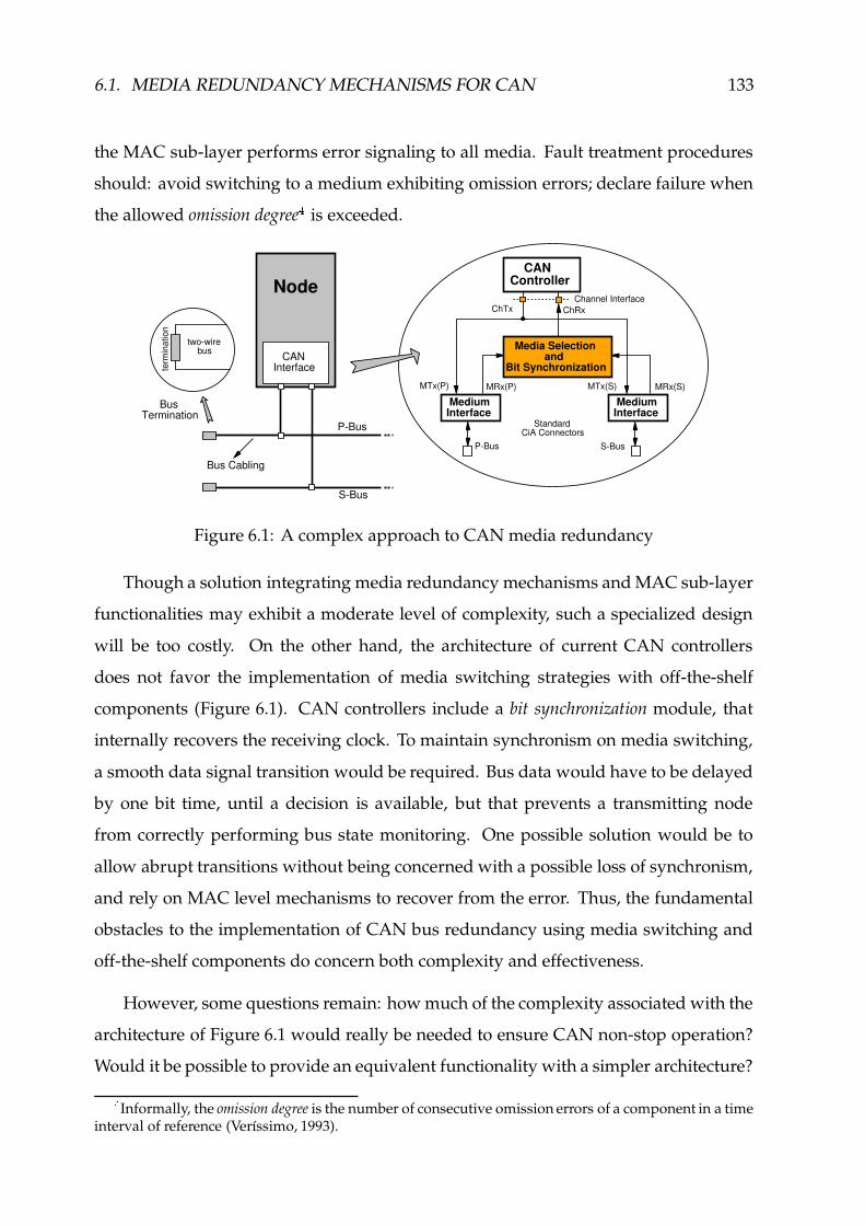
6.1. MEDIA REDUNDANCY MECHANISMS FOR CAN 133
the MAC sub-layer performs error signaling to all media. Fault treatment procedures
should: avoid switching to a medium exhibiting omission errors; declare failure when
the allowed omission degree � is exceeded.
Bus Cabling
two-wire bus
term
inat
ion
Node
CAN Interface
BusTermination
P-Bus
S-Bus
Channel Interface
CANController
ChRxChTx
MediumInterface
S-Bus
StandardCiA Connectors
MRx(S)MRx(P)
MediumInterface
P-Bus
Media Selection andBit Synchronization
MTx(S)MTx(P)
Figure 6.1: A complex approach to CAN media redundancy
Though a solution integrating media redundancy mechanisms and MAC sub-layer
functionalities may exhibit a moderate level of complexity, such a specialized design
will be too costly. On the other hand, the architecture of current CAN controllers
does not favor the implementation of media switching strategies with off-the-shelf
components (Figure 6.1). CAN controllers include a bit synchronization module, that
internally recovers the receiving clock. To maintain synchronism on media switching,
a smooth data signal transition would be required. Bus data would have to be delayed
by one bit time, until a decision is available, but that prevents a transmitting node
from correctly performing bus state monitoring. One possible solution would be to
allow abrupt transitions without being concerned with a possible loss of synchronism,
and rely on MAC level mechanisms to recover from the error. Thus, the fundamental
obstacles to the implementation of CAN bus redundancy using media switching and
off-the-shelf components do concern both complexity and effectiveness.
However, some questions remain: how much of the complexity associated with the
architecture of Figure 6.1 would really be needed to ensure CAN non-stop operation?
Would it be possible to provide an equivalent functionality with a simpler architecture?
�Informally, the omission degree is the number of consecutive omission errors of a component in a time
interval of reference (Verıssimo, 1993).

134 CHAPTER 6. NETWORK AVAILABILITY
The Columbus’ egg idea
To answer those questions, let us analyze the problem under a slightly different
perspective. Let us assume a simplified fault model, considering only the abrupt
interruption of a transmission medium, as shown in Figure 6.2. In addition, let us
assume a single node (Node 1 in Figure 6.2) is transmitting, for example a data or a
remote frame.
Tx
out-partition
BusTermination
Node n
dr
CANInterface
Node 2Node 1
d d d d
CANInterface
CANInterface
P-Bus
S-Bus
Bus Cablinginterruption
in-partition
incorrect value
Figure 6.2: Abrupt partition of a media redundant CAN fieldbus
When a given node transmits a frame, all the nodes located at the in-partition �receive a correct signal on all redundant media interfaces. On the other hand, the
nodes at the out-partition only receive a correct signal on all media interfaces when the
transmitter is sending recessive symbols. Otherwise, the recessive signal from the (idle)
failed media does not match the dominant symbol transmitted in the correct media.
A fault treatment component, to be inserted in the incoming path, between the
medium interfaces and the CAN controller, will allow the delivery of correct results.
Hence, we came up with this Columbus’ egg idea of extending the bare properties of
CAN bus operation to the media interface level (Rufino, 1997a; Rufino et al., 1999b).
Assuming a common CAN implementation, where a dominant value is represented
by a logical zero and a recessive value is represented by a logical one, all the media will
operate in parallel, being seen at the channel interface, as an unique bus implementing
a logical AND function.
�I.e., the partition that includes the transmitter.

6.2. CAN MEDIA REDUNDANCY STRATEGIES 135
Channel Interface
CANController
Bus Cabling
two-wire bus
term
inat
ion
Node
CAN Interface
BusTermination
P-Bus
S-Bus
ChRx
MRx(S)
MediumInterface
S-Bus
StandardCiA Connectors
MediumInterface
P-Bus
MRx(P) MTx(S)MTx(P)
ChTx
Figure 6.3: The Columbus’ egg idea for bus media redundancy in CAN
This solution can be implemented by a conventional AND gate, as exemplified
in Figure 6.3 for a dual-media architecture. The complexity associated with media
switching is avoided. The only disadvantage of this approach is that it is based on too
restrictive a fault model. However, this basic architecture can be enhanced in order to
support a less restrictive and thus more realistic fault model.
6.2 CAN Media Redundancy Strategies
This section discusses our implementation of bus-based media redundancy in CAN,
which is based in the model defined in Section 4.2 and exploits a relevant set of the CAN
physical layer properties enumerated in Figure 4.5 (page 81). In essence, we follow the
results of (Rufino et al., 1999b).
Again, let us assume a network composed of Ë nodes interconnected by a Channel.
Each node )»Ì Ë connects to the Channel by a channel transmitter (outgoing bit stream)
and a channel receiver (incoming bit stream). The channel transmitter and the channel
receiver of node ) are denoted as {tA ,� v and {tA ,(nv , respectively. If the Channel is
composed of several media� Ì Ï ,
z ,� v J � L andz ,(nv J � L
are used to represent the
Medium�
transmitter and receiver interfaces, at node ) . The node is connected by the
Channel transmitter and receiver to a media selection unit (as depicted in Figure 6.4),

136 CHAPTER 6. NETWORK AVAILABILITY
ChTx
nCh
Rx
n
M (1)Txn
M (1)Rxn
M (m)Txn
M (m)Rxn
Standard CAN controller
Standard Media interfaces
Media Selection Unity
Figure 6.4: Channel and Media interfaces
which internally connects to each Medium, accordingly to a given strategy.
For simplicity of exposition, the superscript identifying the node will be omitted,
whenever Channel and Medium refer to the same node. Medium is used to refer an
instantiation of the Channel, comprising the network physical layer and the communi-
cation medium itself.
Operational assumptions
Let us start with a description of some additional assumptions about the network
infrastructure:
N1 - channel redundancy is used, through replicated media (physical and medium layers), but
only one MAC sub-layer.
However, apart from replication, standard CAN components are used. In particu-
lar, we do not exploit any of the fault-tolerant mechanisms of (Philips, 1997b; Alcatel,
1995). Furthermore, we do not assume the use of any specific transmission medium.
Hence, different solutions are allowed for the physical layer: inexpensive differential
pair wiring and non fault-tolerant medium interfaces or fiber optic technology.
N2 - each medium replica is routed differently.
N3 - all media are active, meaning every bit issued from the MAC sub-layer is transmitted
simultaneously on all media.

6.2. CAN MEDIA REDUNDANCY STRATEGIES 137
Assumption N3 is simply enforced by logically connecting the Channel and all the
Medium outgoing links together, thus implementing the function:
z � vZJ � L � {5A � v | � Ì»Ï (6.1)
The Columbus’ egg strategy
The Columbus’ egg strategy extends the PCAN2 wired-AND multiple access prop-
erty (vide Figure 4.5, page 81) to the Media interface level, taking into account the
PCAN1 property. The receive signals of each Medium interface are combined in an
AND function before interfacing the MAC sub-layer, as defined by equation:
{tA*(nv � }� ï�~ z (nvZJ � L (6.2)
where: the symbol î is used to denote the AND function; Ï is the set of Medium
interfaces. For example, in the dual-media architecture of Figure 6.3, Ï ���G�,�v�,� .
This technique provides resilience to Medium partitions (e.g. A and B failures in
Figure 4.3, page 77) and to stuck-at-recessive failures (e.g. failure D in Figure 4.3),
without violating property PCAN3.
Handling stuck-at-dominant failures
A Medium stuck-at-dominant failure prevents equation (6.2) from delivering cor-
rect results. To detect these failures a special-purpose watchdog timer is used. In
CAN, a correct Medium is not allowed to be at a dominant state for more than a given
number of bit times, that we denote ª B4DFE í �:� }a� . This parameter is important because it
provides an upper bound for the delay in the detection of a stuck-at-dominant Medium
failure. The method that we specify for the treatment of stuck-at-dominant Medium
failures is inspired by the rules defined in (BOSCH, 1991; ISO, 1993) for the treatment

138 CHAPTER 6. NETWORK AVAILABILITY
of stuck-at-dominant Channel failures (cf. ÷ 7.3.1 - pages 180, 186 and 188). The value
of ª B4DFE í �:� }a� , defined accordingly with those rules, is given by equation:
ª B4DFE í �:� }a� ��� R � A B4DO� } �¯J(A B4DO� } � �<L � �/ M B4DKE í �8� u(v RW�VEHB SG� � ª �V�-D (6.3)
where, A BCDO� } represents the length of the sequence of consecutive dominant bits, tol-
erated by the CAN fault confinement mechanisms upon the transmission of an active
error flag (BOSCH, 1991; ISO, 1993). Equation (6.3) accounts for the first and subse-
quent violations of the active error flag tolerance. We denote:�/ M B4DKE í �8� u(v RW�VEHB S , as the
allowed Medium receive-error-tolerance margin in the violation of the active error flag
tolerance (cf. ÷ 7.3.1, page 188); ª��V�3D , represents one bit-time.
The state of each Medium is permanently monitored. Upon the detection of a
stuck-at-dominant condition, an indication of Medium�
failure is provided:
z B4DO� � }MJ � L ���� �� « ��·� if ª § J � L � ª BCDFE í �:� }a�Õ�� A � if ª § J � L#� ª B4DFE í �:� }a��� z (nvZJ � L � (6.4)
where, ª § J � L � ª�J z (nvZJ � L � Ó L represents the normalized time elapsed since Medium�is at a dominant state. If it exceeds ª BCDFE í �8� }I� , the Medium has failed. The values true
and false are represented by a logical one and a logical zero, respectively.
Thez BCDO� � } failure indication can be used to directly request the disabling of the
failed Medium, as follows:
z } �FB J � L � z BCDO� � }J � L (6.5)
The receive signal – {tA!(nv – delivered at the channel interface is established by the
receive signals of the non-failed media interfaces, as specified in equation (6.6), where
the symbols î and � are used to denote the AND and the OR functions, respectively.
{tA*(nv � }� ï;~ J z (nvZJ � L � z } �FB J � LiL (6.6)

6.3. ERROR DETECTION MECHANISMS 139
This simple technique secures resilience to Medium stuck-at-dominant failures,
such as failures C or G in Figure 4.3 (page 77).
The resulting increase in the complexity of the media selection unit is moderate:
a simple module-64 binary counter is the core of the additional circuitry required to
support the functionality specified in expression (6.4), for a relevant range of the stuck-
at-dominant Medium receive-error-tolerance margin.
6.3 Error Detection Mechanisms
This section extends the functionality of our architecture by introducing mecha-
nisms able to detect and to account for omission errors � . Provisions for the detection
and monitoring of Medium and node permanent failures are also included.
Operational assumptions
We begin by making the following operational assumptions concerning the observ-
able behavior of CAN at the PHY-MAC interface, as per the standard (BOSCH, 1991;
ISO, 1993):
N4 - there is always a detectable minimum idle period preceding the start of every CAN data
or remote frame transmission.
N5 - there is a detectable and unique fixed form sequence that identifies the correct reception of
a CAN data or remote frame.
N6 - there is a detectable bit sequence that identifies the signaling of errors in the CAN bus.
Let us shortly justify these assumptions. With regard to N4, the {5AC� ¨ � signal is
asserted at the end of each frame transmission, when the minimum bus idle period
�The occurrence of omission errors is usually due to electromagnetic interference. However, they
may also have their origin in subtle causes, such as a defective connector mount or a smashed cable,causing impedance mismatches that may introduce a reflection pattern which sporadically preventscommunication. Other cause may be the incorrect dimensioning of CAN physical layer parameters.

140 CHAPTER 6. NETWORK AVAILABILITY
that precedes the start of every data or remote frame transmission has elapsed. It is
negated at the start of a frame transmission. The normalized duration of the End-Of-
Transmission sequence ( ª�� ¨ � ) includes the nominal three bit intermission ( ª �mGIB ) and is
equal for data/remote and for error/overload frames � . Equation (6.7) takes into account
that a transmission may start at the last bit of the intermission, being ªC� � ª � ¨ � � ª!�V�-D .{tA*� ¨ � �
���� ��� « ��·� if ª�Jl{5A*(nv � L ö ª �Õ�� A Ã� if ª�Jl{5A*(nv � L#� ª � ��{tA*(nv � Ó
(6.7)
With regard to assumption N5, if a data or remote frame transmission ends without
errors, the Frame correct signal ( {tA!m7Ñ � ) is asserted, changing of state accordingly to
expression (6.8). The fixed form sequence of assumption N5 includes the recessive (r)
CRC delimiter, the dominant (d) acknowledgment slot and the recessive acknowledgment
delimiter plus the first six recessive bits of the seven bit end-of-frame delimiter (Figure 6.5).
The frame’s last bit was not included because it is never considered by the recipients
in the evaluation of frame correctness (BOSCH, 1991; ISO, 1993; Rufino et al., 1998b).
{tA*m7Ñ ���� ���� ��� « ��·� if {5A�(Xv � Ó < M M M M < ÕD� A � when {tA � ¨ � (6.8)
Conversely, as defined by assumption N6, when a frame transmission is aborted
due to errors, the {tA��Qu>u signal changes of state accordingly to expression (6.9). Errors
are signaled on the bus through a detectable sequence of dominant bits (assumption
N6), violating the bit-stuffing coding rule. Defining A BCDFEHGHG , as the bit-stuffing width:
{tA*�7u(u �� ���� ��� « ��·� if ª�Jl{tA*(nv � Ó L ö J>A BCDFEHGHG � �<L � ª �V�-DÕ�� A � when {5A�� ¨ � (6.9)
�Being: �<UXW��S[����LH-_'d �MUXW°Y d ��H-ab^È[¡��]¢Ch%d ��H-a@^ , where �<UXW°Y and ��]¢Ch are the normalized durations
of the end-of-frame and of the error/overload delimiters (BOSCH, 1991; ISO, 1993). The normalizedduration associated to the ending sequence of data/remote frames includes the one-bit acknowledgmentdelimiter (cf. Figure 6.5).

6.3. ERROR DETECTION MECHANISMS 141
CRC Sequence CRCDel
ACKSlot
ACK Del
correct data/remote frame ending sequence
r d r r r r rrr
EOF Delimiter
FokCh
EOTCh
r rr
nominal 3-bit intermission
Figure 6.5: End-of-frame sequence monitoring
Frame monitoring
In order to evaluate whether or not a given Medium is exhibiting omission errors,
the reception of data and remote frames is continuously monitored. For every bit,
the signal received from Medium�
–z (nv�J � L – is compared with the channel receive
signal ( {5A�(nv ), until the frame transfer is successfully completed or aborted by errors.
A frame mismatch signal –z m0�rJ � L – is asserted for Medium
�, if the two signals do
not exhibit the same value:
z m*�ÔJ � L �� ��� �� « ��·� ifz (nvZJ � Lw£� {tA*(nv ¤�{5A � �N¥
ÕD� A � when {5A�� ¨ � (6.10)
where, {5A � �N¥ �§¦ {5A�m�Ñ � ¤ ¦ {5A��7u(u signals that a frame transfer is in progress. Once
asserted, thez m*�rJ � L signal is kept in that state even if the two signals become equal
again. It is negated only when {5A�� ¨ � becomes true.
Frame monitoring is suspended: after the detection of an error and assertion of
the corresponding {tA!�7u(u signal; after the successful reception of a data/remote frame,
recognized through the assertion of the {tADm�Ñ � signal. Network errors occuring at the
last bit of the end-of-frame delimiter or during the minimum intermission period are not
accounted for as frame omissions " .!The mandatory two-bit bus idle period between every correct frame transmission.#As we will see in Sections 7.3.1 and 7.3.2, these will be considered overload errors.

142 CHAPTER 6. NETWORK AVAILABILITY
Detecting Medium omissions
Thez m*� J � L signals are used, together with the {tA m7Ñ � and {tA �7u(u signals, in the
update of the Medium omission degree. The following set of auxiliary functions is
defined:
z m*� � B � ¨� ï;~ z m0��J � L (6.11)z ¨ w4uJ � L � {5A�m�Ñ � ¤ z m*�rJ � L(6.12)z ¨ í N J � L � {5A��7u(u/¤ z m0� � B ¤ ¦ z m0�rJ � L (6.13)z¡© w4uJ � L � {5A��7u(u/¤»J ¦ z m*� � B � z m*�rJ � LiL (6.14)
The signal produced by equation (6.11), where the symbol ª is used to denote
a logical sum, simply provides an indication of whether or not a frame mismatch has
been detected at some media. Thez m0� � B signal is asserted if there is at least one
Medium with thez m*�rJ � L signal asserted. The
z m*� � B signal is negated only when
no media report frame mismatches, which may occur in two situations: when no
errors have occurred during the transfer of a frame (Figure 6.6-A); if all the media are
simultaneously disturbed by errors with origin in a common cause (Figure 6.6-B).
As a general rule, an omission error should be accounted for Medium�
whenever
there is a clear indication the error has its origin in that Medium. The omission
degree of Medium�
should be incremented if thez m*� J � L and the {tA m7Ñ � signals are
simultaneously asserted at the end of a frame transfer. This condition, specified by
equation (6.12), means: a correct data or remote frame has been successfully received;
at least one bit in the stream received from Medium�
did not have a correct value, as
illustrated in Figure 6.6-C.
On the other hand, an omission error should also be accounted for if a frame
omission is detected at the Channel interface, unless the error does not have its origin
in any Medium or one cannot unambiguously identify the Medium is producing the
error. Equation (6.13) specifies the conditions for incrementing the omission degree
of Medium�
, upon the assertion of the {tA��7u(u signal: a Medium having itsz m0�rJ � L

6.3. ERROR DETECTION MECHANISMS 143
Esingle-medium errors(both transitions)
(r d)
Medium P d r
Medium S r d
MFm
(P)
MFm
(S)
ChErr
(d r) MUer
(P) MOd
(P)unchanged
MUer
(S) MOd
(S)unchanged
(d r transition) Csingle-medium errors
Medium P r r
Medium S r d
MFm
(P)
MFm
(S)
ChFok
(d r) MOer
(P) MOd
(P) incremented
MOd
(S)=0
Bcommon-mode errorsMedium P d d
Medium S d d
MFm
(P)
MFm
(S)
ChErr
incorrect values
MUer
(P) MOd
(P)unchanged
MUer
(S) MOd
(S)unchanged
(r d)
Medium P d d
Medium S r d
MFm
(P)
MFm
(S)
ChErr
MOch
(P) MOd
(P) incremented
MUer
(S) MOd
(S)unchanged
Dsingle-medium errors(r d transition)
Ano errors
r d
r d
MFm
(P)
MFm
(S)
ChFok
Medium P
Medium S
MOd
(P)=0
MOd
(S)=0
Figure 6.6: Error scenarios in a media redundant CAN fieldbus
signal negated when a frame transfer is aborted due to errors, can be made responsible
for those errors and its omission degree count should be incremented, if there is a frame
mismatch signal –z m*�rJ � L
– asserted for some Medium (Figure 6.6-D).
Conversely, equation (6.14) specifies the conditions that prevent the increment of
the omission degree of a given Medium, in the presence of Channel errors. We discuss
them next:
– the omission degree count of Medium�
should not be modified, despite the
assertion of the {tA��Qu>u signal, if no Medium has thez m*�]J � L signal asserted, as
illustrated in Figure 6.6-B. Easily detectable, through the negation of thez m*� � B

144 CHAPTER 6. NETWORK AVAILABILITY
signal, this situation have its origin in common-mode errors, caused, for example,
by a node with a failed transmitter (Rufino & Verıssimo, 1995).
– the omission degree count of Medium�
should also remain unchanged if the{5A��7u(u andz m0�rJ � L signals are both asserted, because one cannot be sure whether
or not Medium�
has exhibit omission errors�%$
. One particular case of this
scenario is represented in Figure 6.6-E: it concerns single-medium errors, that
nevertheless generate frame mismatches in all media. This scenario calls for fault
treatment procedures where some “incorrect” media are temporarily disabled
(quarantined), to allow operation to proceed with a “correct” set. The specification
of CAN-oriented quarantine techniques, similar to those introduced in (Verıssimo,
1988) for LANs, is under study and it will be reported in a future work.
The functions given by equations (6.12), (6.13) and (6.14) are directly used in ex-
pression (6.15) to account for the omission degree of Medium�
, if an error occurs. For
a Medium exhibiting a correct behavior, i.e. when a frame is correctly received and
no frame mismatches have been reported for that Medium, the corresponding omission
degree count is set to zero, as specified in the last line of expression (6.15).
The use of the {5A!m�Ñ � signal in the error situations of expression (6.15) is required,
because in the presence of overload errors the {tADm�Ñ � and {tA��7u(u signals are both asserted
whenz ¨ }J � L is evaluated, which occurs upon the assertion of the {tA�� ¨ � signal
�'�.
z ¨ }J � L @«8�¬ ���� ������� ������
z ¨ }J � L � �if
z ¨ w4uJ � L � J z ¨ í N J � L ¤ ¦ {tA*m7Ñ � Lz ¨ }J � L ifz¡© w4uJ � L ¤ ¦ {5A*m7Ñ �
�if {tA m7Ñ �¤ ¦ z m*� J � L (6.15)
A Medium that exceeds its omission degree bound should be declared failed and
its contribution to equation (6.6) disabled, by layer management entities.
�%&One exception can be found in a dual-media architecture, when only one ¹ÉYGO¯®Xuw° signal is negated.
Under a single-failure assumption the Medium not exhibiting omission errors will have its ¹SYGOw®'u�°signal asserted.�(�
Signaled in equation (6.15) trough the symbol ±�²f³ ´;µ;¶ .

6.3. ERROR DETECTION MECHANISMS 145
Media monitoring
The signaling of an incorrect recessive value at a given Medium interface does not
disturb the results of the AND function that constitutes the core of our media redun-
dancy mechanisms. Nonetheless, such incidents should be detected and monitored.
The occurrence of Medium partitions and/or of Medium stuck-at-recessive failures
induce the signaling of abnormally long bus idle periods, at the corresponding Medium
interfaces. A special-purpose watchdog timer may be used to detect those failures. The
delay required to detect such kind of failures, whose normalized duration we denote
ª B4DFE í � � ua� , can be defined in conformity with a philosophy that aims to provide an
uniform treatment of stuck-at failures. The value of ª BCDFE í � � ua� , defined by:
ª BCDFE í � � ua� � J(R � A B4DV� } L � ª �V�-D (6.16)
is inspired by equation (6.3) and fulfills two fundamental conditions: it is longer than
the sequence of recessive bits that precedes the assertion of the {5A m7Ñ � signal (Figure 6.5),
in every correct reception of a data/remote frame; it is shorter than the minimum period
of inactivity, expected at the receiver interface of a failed Medium during the reception
of a data/remote frame, for any node located at the out-partition� � . That is:
ª0� ¨ m � ª BCDFE í � � ua� � ª í DO� ��ª í u í (6.17)
where, ª*� ¨ m is the normalized duration of the end-of-frame delimiter. The definition
of the error detection upper bound accounts for the normalized nominal durations of
the control ( ª í DO� ) and CRC� � ( ª í u í ) fields in a data/remote frame. No other frame field is
included, because: the data field may have a zero length; it may exist network activity
at any partition during the arbitration field and at the acknowledgment slot (Figure 6.7).
Whenever a node detects an abnormal recessive period in Medium�
during the
reception of a data/remote frame, thez � u¸·�J � L signal is asserted, as described by the
�%�I.e., the partition that does not include the transmitter.�4�The value defined for ��¹Lº¸¹ includes the 15-bit CRC sequence plus the one-bit CRC delimiter.

146 CHAPTER 6. NETWORK AVAILABILITY
BusTermination
P-Bus
S-BusBus cabling interruptionout-partitionin-partition
winning Tx
Node n
CANInterface
Node 1
CANInterface
SOF arbitration field control field CRC sequence EOFCRC
Del.ACK Del.
ACK slot
possible multiple Tx activity (both partitions)
failure induces Medium inactivity (out-partition)
min. period of inactivity
frame transmission period
in-partition
Figure 6.7: Detecting a partition failure in a media redundant CAN fieldbus
following expression:
z � u¸·�J � L �� ���� ��� « ��·� if ª*(ÈJ � L � ª BCDFE í � � ua�»¤ ¦ {tA*m7Ñ �Õ�� A � when {5A�� ¨ � (6.18)
where, ª�( J � L � ª�J z (nvZJ � L � Lrepresents the normalized time elapsed since Medium
�is at a recessive state. If it exceeds ª BCDFE í � � ua� , the
z � u¸·�J � L signal is asserted. This
signal is negated only when {tA�� ¨ � becomes true.
An indication of Medium�
abnormal idleness should be delivered to higher layers,
e.g. for diagnose purposes. However, this indication should be generated only upon
the reception of a correct data/remote frame, at the Channel interface. Such a condition,
recognized through the assertion of the {tADm7Ñ � signal, is specified in equation (6.19) and
ensures that the recognition of an abnormal bus idle period is not disturbed by the
occurrence of other network errors.
z � } � wbJ � L ����� ��� « ��·� if
z � u¸·�J � L ¤�{5A*m7Ñ �Õ�� A Ã� when {tA*� ¨ � (6.19)
To distinguish Medium partitions from stuck-at-recessive failures, it is required
to continuously monitor the activity of each Medium, as specified by equation (6.20).
Thez } B signal is asserted if a dominant bit is detected at Medium
�interface, being
negated only when the {5A�� ¨ � becomes true.

6.3. ERROR DETECTION MECHANISMS 147
z } B J � L �� ��� �� « ��·� ifz (nvÃJ � L � Ó
ÕD� A � when {tA�� ¨ � (6.20)
Thez } B signal remains negated for any Medium interface affected by a stuck-at-
recessive failure.
Channel monitoring
The error detection mechanisms introduced earlier in the architecture of the CAN
media selection unit do not take into account that a given node may fail and start to
transmit only dominant symbols at the Channel interface. The operation of the entire
network may be disturbed by this single failure.
One way to provide resilience to such a Channel failure would be to prevent
Medium disabling, whenever a stuck-at-dominant condition is signaled for all media
and rely on CAN fault confinement mechanisms to perform the removal of the failed
node. However, this solution exhibits some severe drawbacks:
f additional measures (e.g. node parameterizing) and/or management components
may be required to ensure that only the node with the failed transmitter is removed,
by the CAN fault confinement mechanisms;
f there may be a significant delay until the withdraw of the failed node, by the native
CAN fault confinement mechanisms (cf. Table 7.1, page 184);
f the simultaneity of the stuck-at-dominant indications provided by equation (6.4), is
not guaranteed for all media, in the presence of other network errors.
A simpler solution uses a dedicated watchdog timer. The period required to detect
the Channel transmitter failure has a normalized duration that we denote ª�BCDFE í � � D v and
define in conformity with the rules of CAN fault confinement mechanisms specified in
(BOSCH, 1991; ISO, 1993). The value of ª�BCDFE í � � D v is thus given by equation:
ª BCDFE í � � D v �¼� R � A BCDO� }È� J(A B4DO� }p� �<L � �/ M B4DKE í �8��D v � � ª �V�-D (6.21)
148 CHAPTER 6. NETWORK AVAILABILITY
where,�/ M B4DFE í �:��D v is the stuck-at-dominant transmit-error-tolerance margin (cf. ÷ 7.3.1,
pages 180 and 186). The value of�/ M B4DKE í �8��D v should obey to the relation:
�½� �/ M B4DFE í �:��D v � �/ M BCDFE í �8� u(v RW�VEHB S (6.22)
The definition in equation (6.22) of a transmit-error-tolerance margin,� M B4DFE í �:��D v ,
lower than�/ M B4DKE í �8� u(v RW�VEHB S , the stuck-at-dominant Medium receive-error-tolerance margin,
guarantees that the Channel transmitter failure is detected earlier than the stuck-at-
dominant condition induced at the Medium receiver interfaces. The value of�/ < BCDFE í �:��D v
can be set to zero, as specified in equation (6.22), because the resulting error detection
delay is longer than the duration of the longest sequence of dominant symbols signaled
at the Channel transmitter interface, in the absence of permanent failures� � .
The state of the Channel is permanently monitored. Upon the detection of a stuck-
at-dominant condition, an indication of a permanent failure in the Channel transmitter
is provided:
{tA B4DO� � � v � ��� �� « ��·� if ª�Jl{5A � v � Ó L � ª B4DKE í � � D vÕ�� A � when mngt. request
(6.23)
The {5A B4DV� � � v signal is negated only upon the issuing of a specific layer manage-
ment request. The indication provided by {tA B4DO� � � v can be used directly to disable
the medium interface transceiver circuitry, whenever those components support that
functionality (e.g. (Alcatel, 1995; Infineon, 2000)). Otherwise, the architecture of the
media selection unit should include the circuitry required for that purpose (Figure 6.8).
6.4 CAN Media Selection Unit Design
The architecture of the media selection unit, to be inserted between the redundant
media interfaces and a standard CAN controller, is depicted in Figure 6.8. Apart from
�4�The normalized duration of this sequence is given by �����(^a¾¿M;KWÀ�[Á®b®KTm^C_F`baiaÃdroU°cd\T-aihkj(l�°'Å ���LH-_ , where T-achkjPl
is the nominal length of an error flag. The length parameters obey to the relation: T4^C_F`baca*Â{T-aihkj(l!Â{TF^4_F� � .
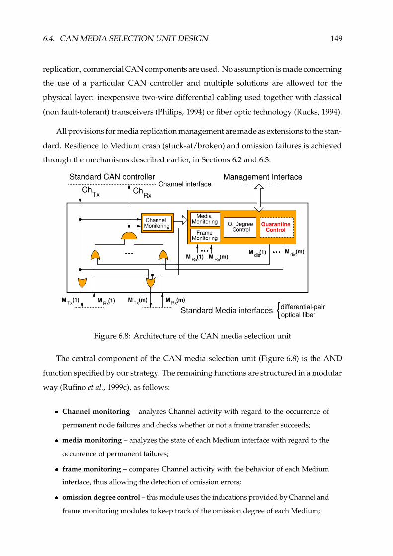
6.4. CAN MEDIA SELECTION UNIT DESIGN 149
replication, commercial CAN components are used. No assumption is made concerning
the use of a particular CAN controller and multiple solutions are allowed for the
physical layer: inexpensive two-wire differential cabling used together with classical
(non fault-tolerant) transceivers (Philips, 1994) or fiber optic technology (Rucks, 1994).
All provisions for media replication management are made as extensions to the stan-
dard. Resilience to Medium crash (stuck-at/broken) and omission failures is achieved
through the mechanisms described earlier, in Sections 6.2 and 6.3.
ChTx Ch
Rx
Standard CAN controller
{differential-pairoptical fiber
Channel interface
ChannelMonitoring
M (1)RxM (1)Tx M (m)Tx M (m)Rx
Management Interface
M (m)Rx
M (m)disM (1)disM (1)Rx
FrameMonitoring
Quarantine Control
O. Degree Control
MediaMonitoring
Standard Media interfaces
Figure 6.8: Architecture of the CAN media selection unit
The central component of the CAN media selection unit (Figure 6.8) is the AND
function specified by our strategy. The remaining functions are structured in a modular
way (Rufino et al., 1999c), as follows:
f Channel monitoring – analyzes Channel activity with regard to the occurrence of
permanent node failures and checks whether or not a frame transfer succeeds;
f media monitoring – analyzes the state of each Medium interface with regard to the
occurrence of permanent failures;
f frame monitoring – compares Channel activity with the behavior of each Medium
interface, thus allowing the detection of omission errors;
f omission degree control – this module uses the indications provided by Channel and
frame monitoring modules to keep track of the omission degree of each Medium;
150 CHAPTER 6. NETWORK AVAILABILITY
f quarantine control – under development. Aims to control the effects of single-
medium errors that nevertheless affect the behavior of media monitoring functions
at all media interfaces.
The attributes of the CAN protocol can and should be exploited in the design of
media redundancy management modules, in order to keep complexity low (Rufino
et al., 1999c). For example, stuck-at dominant and recessive failures are mutually
exclusive events, and this may be used to reduce the complexity of the media monitoring
circuitry. A similar approach can be followed in the design of the pattern recognition
machinery that identifies the error signaling and frame termination sequences.
At a slightly different level, the assignment of pre-defined constant values to a
relevant set of protocol-related parameters, such as the error tolerance margins, allows
to simplify the implementation of CAN monitoring mechanisms, at the cost of a lower
flexibility in the configuration of those parameters.
Complexity issues are of major relevance to the integration of the media selection
unit in a single, inexpensive, medium capacity programmable logic device. A prototype
of the media selection unit, aiming its integration in a field programmable gate array, is
currently being specified in VHDL� � . A preliminary specification of such a design is
described in (Matias, 2000).
Assuming a fundamental role to the integration of the CAN media selection unit in
the system architecture, the set of functions defined for the corresponding management
interface are summarized in Figure 6.9.
The operation of the media selection unit is started upon the issuing of the layer
management action specified in the first-half of Figure 6.9, which defines the rate of
data signaling in the bus and the allowed media omission degree bound.
The second-half of Figure 6.9 specifies how the failures detected by the CAN media
selection unit are signaled to higher layers. Those layer management notifications
allow the implementation of high-level applications, providing diagnose functions
�%�Very High-Speed Integrated Circuits (VHSIC) Hardware Description Language. A fairly compre-
hensive introduction to VHDL can be found in (Ashenden, 1990).

6.5. CAN FULL SPACE-REDUNDANCY 151
Invocation Primitives (can-msu.req)
Description Parameters
Initialize Ã8ÄyÅ�Æ bit rate signaling parametersò�� media omission degree bound
Notification Primitives (can-msu.nty)
Description Condition Parameters
Omission degree exceeded Ç ¨ }¯È+ò�� É failed Medium
Stuck-at-dominant Medium Ç»B4DO� � } É failed Medium
Stuck-at-recessive Medium Ç � } � w!ÊÌË�Ç } B É failed MediumɬàbÆ message identifier
Medium partition Ç � } � w ÊÌÇ } B É failed MediumɬàbÆ message identifier
Stuck-at-dominant Channel ÍÏÎ B4DV� � � v node transmitter failure
Figure 6.9: CAN media selection unit management primitives
extremely helpful to maintenance activities. For example: the signaling that a given
Medium has failed calls for an action to repair the network infrastructure. Furthermore,
the functionality provided by the CAN media selection unit allows to distinguish a
stuck-at-recessive from a medium partition failure and the set of parameters signaled
upon failure detection permits a high-level diagnose application to establish a node
connectivity matrix, useful to pinpoint the location of the failure in the network cabling.
Crucial for such a kind of applications, the correctness of every message identifier
captured at the PHY-MAC interface and signaled upon the detection of a given Medium
failure, is secured. Such notifications are issued only in the absence of Channel errors,
as specified in equation (6.19).
6.5 CAN Full Space-Redundancy
In order to complete our analysis of highly available CAN fieldbus architectures,
we discuss next how complex it will be to design and implement full space-redundancy
in CAN.

152 CHAPTER 6. NETWORK AVAILABILITY
Full space-redundancy, replicating media and network controllers, traditionally
exhibits a cost higher than simple media redundancy. However, CAN is a low-cost
technology: stand-alone CAN controllers are widely available at rather low prices
(Intel, 1995; Philips, 1997a); a few microcontroller families already provide devices
with dual CAN interfaces (Motorola, 1996; Motorola, 1998; Dallas, 1999).
This opens room for the design and implementation of CAN-based full space-
redundant network infrastructures, at acceptably low costs. The architecture of a CAN
space-redundant platform is not complex to design, as illustrated in Figure 6.10, for
a dual-redundant solution. For each CAN controller, the channel interface transmit
and receive signals are connected directly to the corresponding medium interface sig-
nals. Redundancy management is performed by a software layer (not represented in
Figure 6.10) built directly on the top of the standard MAC sub-layers.
Bus Cabling
two-wire bus
term
inat
ion
Node
Dual-CAN Interface
BusTermination
Bus A
Bus B
Bus A
MediumInterface
MediumInterface
Channel Interfaces
CANController
CANController
ChTx(A) ChRx(A) ChRx(B)ChTx(B)
Bus B
MRx(B)MTx(B)MRx(A)MTx(A)
StandardCiA Connectors
Figure 6.10: Full space-redundancy in CAN
Next, we discuss the pros and cons of using either simple media-redundancy or
full space-redundancy techniques in the design of a CAN-based fault-tolerant real-time
communication system.

6.6. CAN MEDIA AND FULL SPACE-REDUNDANCY 153
6.6 CAN Media and Full Space-Redundancy
This section discusses the main attributes of CAN media and full space-redundancy
schemes and performs their comparison. In addition, it is discussed how the two
redundancy approaches can be combined in the same architecture. The contents of this
section are based on the results of (Rufino, 1997b).
Attributes of CAN media redundancy
The main attributes of CAN media redundant architectures are characterized next.
Both positive and negative aspects are analyzed.
� network availability – replication of the CAN physical and medium layers provides
resilience to network stuck-at, partition and omission failures, on the assumption
that permanent failures do not affect simultaneously all media replicas (cf. ÷ 4.2).
� narrowed coverage of faults – simple media redundancy cannot provide resilience to
common mode errors that temporarily may affect all the media simultaneously.
These errors may have its origin, for example, in a node with a failed transmitter
or a failed receiver. Though CAN has means to recover from such errors, that
recovery takes time and meanwhile the network is completely down, because
each node can communicate with no one.
� redundancy transparency – with the possible exception of network configuration ac-
tions by layer management entities, all provisions for redundancy are introduced
at the lowest layers of communication. The operation of protocols above the
PHY-MAC interface is transparent with regard to the use of media redundancy.
� hardware-based redundancy management – the need for a specialized hardware in-
frastructure is not necessarily a disadvantage. All actions required for the man-
agement of redundancy are performed by dedicated machinery, without intro-
ducing any protocol processing overheads. This can be of major importance
in simple CAN infrastructures, with modest processing resources, where media
redundancy may be the only solution for achieving high network availability.
154 CHAPTER 6. NETWORK AVAILABILITY
Attributes of CAN full space-redundancy
The fundamental attributes of CAN full space-redundant architectures are charac-
terized next, once again analyzing both positive and negative aspects.
� network availability – a full space-redundant CAN communication infrastructure
should provide availability figures similar to those furnished by simple media
redundancy, for the same fault assumptions and level of replication.
� broad coverage of faults – assuming independence of channel failures, the use of
full space-redundancy provides tolerance to temporary and permanent channel
partitions.
� tight timeliness – the use of full space-redundancy allows to narrow the variability
of CAN timing properties, in the presence of network errors. The timeliness of
CAN error-free operation may be preserved by transmitting the same message on
all channels. Assuming channel failures are independent, a copy of that message
will be delivered to all recipients, at least by one channel.
The provision of strict real-time guarantees at the MAC sub-layer interface is
obtained by securing CAN glitch-free operation in the presence of inaccessibility
faults.
� software-based redundancy management – to assure transparency with regard to the
use of network redundancy, a given number of actions have to be performed at
a software layer, to be inserted between the redundant MAC sub-layers and the
higher layer protocols. For example: the same message may need to be queued
for transmission on all the communication channels; each channel receive buffer
has to be read upon the reception of a message.
This software layer introduces processing overheads which may have a non-
negligible impact on CAN platforms with modest processing resources. It is
common knowledge among CAN practitioners that in some simple CAN infras-
tructures, built around small microcontrollers, it may be difficult to handle a
high data throughput. For these architectures, full space-redundancy may not be
recommended.

6.6. CAN MEDIA AND FULL SPACE-REDUNDANCY 155
� extra network bandwidth – the glitch-free operation and the tight timeliness char-
acteristics of full space-redundant architectures can be traded with a lower uti-
lization of the available network bandwidth. Under error-free operation, each
message is queued for transmission at a single channel interface. Given suffi-
ciently low network error rate figures, that may lead to significant savings in the
utilization of the network bandwidth.
The extra network bandwidth can be used to: increase the probability of having
soft real-time traffic meeting the corresponding timeliness requirements; increase
the network bandwidth available for non real-time traffic.
Upon the detection of a network error, the message queuing policy changes and
each message will be submitted for transmission at multiple channel interfaces.
The timing guarantees achieved with this adaptive scheme are naturally less tight
than in a traditional space-redundant configuration. The worst-case time required
to detect the network error and perform mode switch, Ü/Ð N � � B , must be added
to worst-case message transmission delay, Ü D } , defined in MCAN7 (Figure 4.6,
page 82). The method is effective because Ü/Ð N � � BfÑ Ü � , � , the worst-case duration
of an inaccessibility period.
Comparing CAN redundant architectures
The main attributes of the different CAN redundancy schemes are compared in
Figure 6.11. If no redundancy is used, the system will exhibit the availability and the
fault coverage secured by the native CAN protocol.
MAC Redundant Network Fault Tight Processingarchitecture media availability coverage timeliness overheads
single no low low no noyes high high
dual no high very high yes yesyes very high very high
Figure 6.11: Main attributes of CAN redundant architectures

156 CHAPTER 6. NETWORK AVAILABILITY
The use of simple media redundancy allows the provision of resilience to Medium
crash (stuck-at/broken) and omission failures in a highly available network architec-
ture. Glitch-free operation and tight timeliness characteristics can only be achieved
with full space-redundant architectures, at the cost of additional message processing
overheads.
Combining CAN media and full space-redundancy
The combination, in a single network architecture, of full space-redundancy and of
simple media redundancy, allows to achieve all the features of network redundancy
together with very high levels of network availability.
In CAN, the combination of media and full space-redundancy is extremely simple
to achieve, as illustrated in Figure 6.12. Each network cable has two differential pairs:
� one pair is used as a primary bus� � (P-Bus) for a given channel interface, as
illustrated in Figure 6.12;
� the other pair, is used as a secondary bus (S-Bus) for a different channel
interface.
The architecture of Figure 6.12 illustrates the design of a Dual-MAC/Quad-Bus
CAN architecture. Media redundancy is supported by the CAN media selection unit
described in Section 6.4. The medium interface receive signals, for both primary and
secondary buses, are combined in the AND-based media selection unit, to obtain the
channel receive signal.
The architecture of Figure 6.12 includes two different CAN controllers. A soft-
ware/firmware protocol layer (not represented in Figure 6.12), to be inserted between
the CAN standard layer and higher level protocols, is responsible for managing com-
munication redundancy. If desired, this layer can ensure a transparent operation of
higher level protocols, with regard to network redundancy.
�%�This designation is completely arbitrary because, in the absence of permanent medium errors, all
media replicas are active.

6.6. CAN MEDIA AND FULL SPACE-REDUNDANCY 157
MediumInterface
Dual-Bus A
P-BusCh (A)
MediumInterface
S-BusCh (B)
MediaSelection
Dual-Bus Cabling
two-wireprimary bus (P-Bus)
term
inat
ion
two-wiresecondary bus (S-Bus)
term
inat
ion
Node
Dual-CAN Interface
Dual-BusTermination
Dual-Bus A
Dual-Bus B
Channel Interfaces
CANController
CANController
ChTx(A) ChRx(A) ChRx(B)ChTx(B)
Extended use of thestandard CiA connector
MediaSelection
MediumInterface
Dual-Bus B
P-BusCh (B)
MediumInterface
S-BusCh (A)
Figure 6.12: Combining media and full space-redundancy in CAN
The physical attachment of the network controller to each dual-bus infrastructure
has to support a dual-media connection. Fortunately, this attachment can be made
compliant with the definition of the CiA standard connector (CiA, 1994). In our pro-
posal, the standard connector definition is extended to allow the use of two reserved
pins, shown in Figure 6.13 through a gray shaded label, to support the connection of
the secondary bus. Other types of connectors, such as those specified in (CiA, 1999),
can be easily extended to support a combination of network/media redundancy.
1
2
3
4
5
6
7
8
9 CAN_V+ (optional power)
reserved (error line)
CAN_H (CiA standard)
optional CAN ground
CAN ground
optional CAN shield
(secondary) CAN_H
(secondary) CAN_L
(CiA standard) CAN_L
Figure 6.13: Extending the use of the standard CiA connector
The high levels of dependability achieved by this unified architecture, namely the
very high network availability in the presence of permanent failures, glitch-free com-
munication and tight timeliness characteristics do represent a step toward a possible
utilization of CAN in safety-critical applications. The same architecture supports an
alternative design solution, where the tight timeliness guarantees are traded by an
improvement in the available network bandwidth and overall system throughput.

158 CHAPTER 6. NETWORK AVAILABILITY
6.7 Summary
This chapter is entirely dedicated to the design and implementation of highly
available network architectures for dependable systems built around the CAN fieldbus.
In particular, the following contributions are thoroughly addressed:
� detailed specification of an innovative and extremely simple method for the implementation
of media redundancy in CAN, providing resilience to Medium crash (stuck-at/broken)
and omission failures;
� definition of a modular architecture for a CAN media selection unit, aiming the integration
of that method in a single, inexpensive programmable logic device, and specification of the
corresponding layer management interface;
� comparative analysis of simple media redundancy and full space-redundancy in CAN and
definition of an architecture that combines both solutions.

Securing Real-TimeProperties
A bounded and known message delivery latency, in the presence of disturbing
factors such as overload or faults, is a fundamental requirement of communications
in reliable real-time systems. In many communication infrastructures that bound can
be unfolded, with successively lower guarantees, in a given number of network access
classes, where the system urgency requirements can be mapped. Next, we discuss how
the real-time communications requirement can be achieved in systems built around the
CAN fieldbus.
To obtain a reliable real-time behavior out of a standard LAN or fieldbus com-
munication network, CAN included, one have first to reason about the failure modes
that must be taken into account. In addition, some specific architectural factors may
also need to be considered. For example, the LAN or the fieldbus infrastructure may
not be replicated, with the possible exception of the physical – medium and electrical
signaling – level, making unavoidable that the effects of transmission errors will show
at the LLC-level interface.
Without loss of generality, let us recall from Chapter 4 the failure modes that we
have previously assumed for CAN-based systems: timing failures (delays) due to
transient overloads; omission failures (lost frames) due to transmission errors; network
partitions (physical/virtual). To enforce system correctness in the time-domain, the
effects of those disturbances in network operation need to tolerated or at least limited.
In addition, let us assume that the transmission Channel is not replicated, and use a
divide-and-conquer strategy that treats in isolation each of the faults we consider in
our model: timing, omission, partitions.
159

160 CHAPTER 7. SECURING REAL-TIME PROPERTIES
In this context, the following conditions must be observed to secure the attributes
of reliable real-time communication (Verıssimo, Rufino & Rodrigues, 1991):
RT1 - enforce bounded delay from request to transmission of a frame�, given the
worst-case load conditions assumed (avoid timing failures);
RT2 - ensure that a message � is delivered despite the occurrence of omissions
(tolerate omission failures);
RT3 - control partitions.
Condition RT1 assures that a frame is sent within a known time bound, even if it
does not arrive. Enforcing RT1 requires an user-level control of the offered load and
determinism in the MAC-level mechanisms of the LAN or fieldbus. Condition RT2 has
been introduced to tolerate omission faults and ensures that a message is delivered,
even if that implies the transmission of several frames. Enforcing condition RT2 at the
lower levels of communication is a cost-effective solution, given that fieldbuses must
often operate in harsh environments (Gallagher, 1985; Flint & Kent, 1981; IBET, 1995).
Condition RT3 is related to maintain connectivity between network nodes. Achieving
RT3 in non-replicated network infrastructures is a complex problem that requires the
utilization of appropriate design techniques (Verıssimo, 1993). Hence, this chapter
thoroughly discusses how to secure RT3 in CAN-based systems (Rufino & Verıssimo,
1997; Rufino et al., 2000).
7.1 Enforcing a Bounded Transmission Time
The guarantee that a given frame is locally transmitted within a bounded and
known time (condition RT1) depends on multiple factors. The frame transmission
delay upper bound (vide property MCAN7 in Figure 4.6, page 82), is related to: the
node traffic patterns, defining the temporal characteristics of message transmit requests
(e.g. interarrival time, message length and urgency level); the global offered load; the
�Network level information packet.�User level information packet.
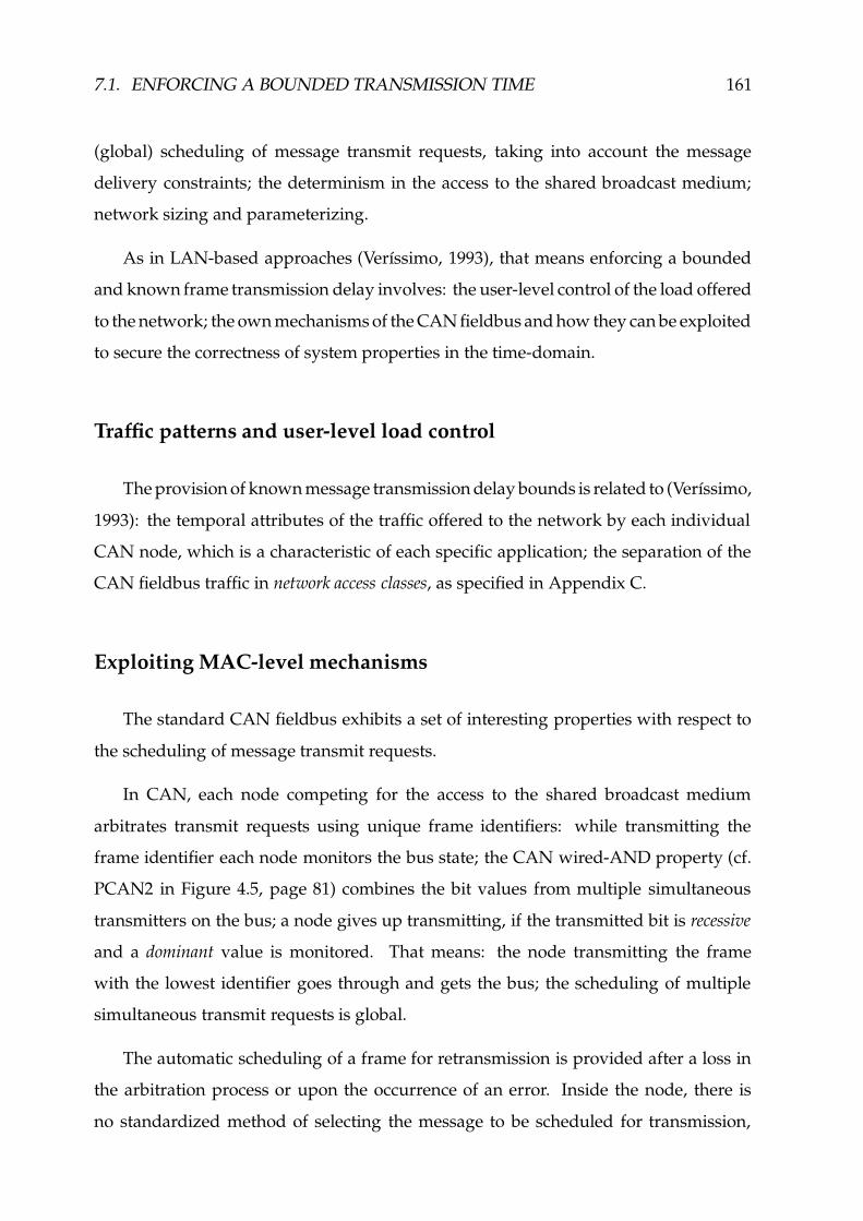
7.1. ENFORCING A BOUNDED TRANSMISSION TIME 161
(global) scheduling of message transmit requests, taking into account the message
delivery constraints; the determinism in the access to the shared broadcast medium;
network sizing and parameterizing.
As in LAN-based approaches (Verıssimo, 1993), that means enforcing a bounded
and known frame transmission delay involves: the user-level control of the load offered
to the network; the own mechanisms of the CAN fieldbus and how they can be exploited
to secure the correctness of system properties in the time-domain.
Traffic patterns and user-level load control
The provision of known message transmission delay bounds is related to (Verıssimo,
1993): the temporal attributes of the traffic offered to the network by each individual
CAN node, which is a characteristic of each specific application; the separation of the
CAN fieldbus traffic in network access classes, as specified in Appendix C.
Exploiting MAC-level mechanisms
The standard CAN fieldbus exhibits a set of interesting properties with respect to
the scheduling of message transmit requests.
In CAN, each node competing for the access to the shared broadcast medium
arbitrates transmit requests using unique frame identifiers: while transmitting the
frame identifier each node monitors the bus state; the CAN wired-AND property (cf.
PCAN2 in Figure 4.5, page 81) combines the bit values from multiple simultaneous
transmitters on the bus; a node gives up transmitting, if the transmitted bit is recessive
and a dominant value is monitored. That means: the node transmitting the frame
with the lowest identifier goes through and gets the bus; the scheduling of multiple
simultaneous transmit requests is global.
The automatic scheduling of a frame for retransmission is provided after a loss in
the arbitration process or upon the occurrence of an error. Inside the node, there is
no standardized method of selecting the message to be scheduled for transmission,

162 CHAPTER 7. SECURING REAL-TIME PROPERTIES
DeviceParameter Intel Philips Microchip Dallas Siemens Motorola
82527 SJA1000 MCP2510 80C390 C167 MPC555
Buffers (Rx+(Rx/Tx)) 1+14 1+1Tx 2+3 1+14 1+14 16 Rx/TxTx-first buffer msg. ID f
scheduling buff. nb. f f f fpolicy priority f
Rescheduling arb. loss fafter error f
Figure 7.1: Transmit buffer management in commercial CAN controllers
at a given time. The attributes of a relevant set of commercial CAN controllers with
that regard, are summarized in Figure 7.1. One CAN controller implements a policy
that selects for transmission the message with the lowest identifier (msg. ID option, in
Figure 7.1). Most controllers transmit first the message stored in the buffer with the
lowest number reference (buff. nb., in Figure 7.1). One particular controller (Microchip,
1999) uses a special-purpose priority field that software components can co-relate with
either of the previous parameters, upon submission of a transmit request.
The management of message transmit buffers is of fundamental importance to pre-
vent priority inversion, namely when the ordering of message transmissions by the
CAN controller depends on the buffer numbering. If priority inversion occurs, the
results of a traditional message schedulability analysis may be invalid. A comprehen-
sive set of priority inversion scenarios, their degree of severity and impact in terms of
message schedulability, is analyzed in (Meschi et al., 1996).
In any case, the main conclusion to be drawn from our previous analysis of the
CAN arbitration process is that the definition of message/frame identifiers is crucial to
the provision of CAN timeliness guarantees. Despite its importance, we do not address
this issue in detail, since it has been thoroughly studied by a number of authors:
� in (Tindell & Burns, 1994b), the message identifiers are assigned fixed-priorities
defined accordingly with a deadline-monotonic (DM) scheduling, given a static
set of messages. The guarantee that the message timeliness requirements are met

7.2. HANDLING OMISSION FAILURES 163
is provided by an off-line feasibility test. This method was applied with success
to the SAE automotive control systems benchmark;
� in (Zuberi & Shin, 1995), it is used a combination of dynamic and static scheduling.
Hard real-time messages with tight deadlines are scheduled using a mixture of
EDF � and DM methods while other hard real-time messages are scheduled using
the DM method alone. Non real-time messages are ordered by a fixed-priority
scheduling;
� an approach combining dynamic and static scheduling is also followed in (Livani
et al., 1998). A calendar-based resource reservation scheme allocates in advance all
the time slots required to hard real-time communication. Soft real-time traffic is
scheduled according to an EDF strategy and non real-time messages are assigned
fixed priorities.
The use of dynamic scheduling requires the on-line update of message identifiers.
This is possible because most of the currently available CAN controllers: provide a
dual-port access to the message buffers; reload the internal outgoing buffer, each time
an arbitration process is started (cf. Figure 7.1).
Finally, note that the functions assigned to the message identifier field, in our
approach to the design of real-time CAN communication systems (cf. Appendix C),
are flexible enough to allow the implementation of a comprehensive set of message
scheduling techniques, including those described in the works cited earlier.
7.2 Handling Omission Failures
The standard CAN protocol has a built-in method to handle omission failures, sup-
ported on a comprehensive set of error detection and signaling mechanisms. Upon the
signaling of an error: the recipients discard the incorrect frame; the sender automati-
�EDF, Earliest Deadline First. Actually, the method followed in (Zuberi & Shin, 1995) is a variant
of EDF that uses the slack time (time to deadline) instead of the deadline itself. Excellent tutorials onreal-time scheduling can be found in (Audsley & Burns, 1990; Redell, 1998).
164 CHAPTER 7. SECURING REAL-TIME PROPERTIES
cally submits the same message for retransmission. Most omission failures are handled
consistently by all nodes.
However, we have identified in Section 4.1.1 a set of subtle failure modes that
may lead to an inconsistent delivery of a message: a node in the error passive state
detects an incorrect incoming frame and it is unable to signal the error to other nodes;
a sender fails, after the inconsistent dissemination of a message and before message
retransmission.
Given these error scenarios cannot be ignored, at least for highly fault-tolerant
applications of CAN, one cannot rely on the operation of the CAN protocol alone
to secure condition RT2 (page 160). A solution to this problem has been thoroughly
discussed in previous chapters, where we have specified the control methods and/or
the mechanisms required to: avoid the erratic behavior of error passive nodes (cf. ÷ 4.1.1);
ensure that a given message is delivered, despite sender failure (cf. ÷ 5.2).
7.3 Controlling Partitions: Inaccessibility
Let a network be partitioned when there are subsets of the nodes which cannot
communicate with each other � . This is the classical definition, and it is normally
attached to a notion of physical disconnection, a problem that we have thoroughly
addressed in Chapter 6.
However, such a definition is helpful in explaining the notion of inaccessibility.
In a “sane” network the occurrence of certain events in its operation (e.g. entry or
leave of new nodes) or of individual failures (such as: bit errors; transmitter or receiver
glitches; node failures; token loss) may produce side-effects on the other nodes, which
are a subtle form of partitioning, virtual rather than physical. Standard LANs and
fieldbuses have their own means of recovering from these situations, but since this
recovery process takes time, the network will exhibit periods where service is not
provided to some or all of the nodes.
�The subsets may have a single element. When the network is completely down, all subsets have a
single element, since each node can communicate with no one.

7.3. CONTROLLING PARTITIONS: INACCESSIBILITY 165
In short, an inaccessibility fault occurs when a component temporarily refrains from
providing service, on account of a foreseen (specified) transition in its internal state. If
such kind of faults are not tolerated, timeliness of applications is at stake, which is not
acceptable in a hard real-time system. In consequence, a semantics of inaccessibility
faults must be defined, so that adequate fault-tolerance techniques may be devised.
The problem of inaccessibility was thoroughly equated in previous works on LANs
(Verıssimo & Marques, 1990; Verıssimo, Rufino & Rodrigues, 1991). Its formal defini-
tion, in (Verıssimo & Marques, 1990), is recapitulated next.
Inaccessibility:
i) a component temporarily refrains from providing service;
ii) its users perceive that state;
iii) the limits of the periods of inaccessibility (duration, rate) are specified;
iv) violation of those limits implies the permanent failure of the component.
The approach taken to tolerate inaccessibility faults is based on the following idea:
if one knows for how long it lasts, then reliable real-time operation of the system
is possible, provided that those glitch periods are acceptably short, with regard to
service requirements. Hence, as specified in (Verıssimo, Rufino & Rodrigues, 1991), to
implement inaccessibility control in a given LAN or fieldbus all that is necessary is to
complement the LAN or fieldbus functionality, in order to:
� guarantee recovery from all conditions leading to partition (physical or virtual)
in a given failure scenario, i.e. reestablish connectivity among affected nodes;
� ensure that the number of inaccessibility periods and their duration have a bound
and that it is suitably low for the service requirements;
� accommodate inaccessibility in protocol execution and timeliness calculations, at
all the relevant levels of the system.
That means, the techniques used in the control of inaccessibility will: “allow” a
set of temporary network partitions; stipulate limits for the duration of the resulting

166 CHAPTER 7. SECURING REAL-TIME PROPERTIES
glitches during a protocol execution; require from the network components some self-
assessment capability. This way, all partitions are controlled. Uncontrolled partitions
are of course still possible, because systems do fail, but that event means the total and
permanent failure of the real-time communication system.
Next, we discuss in detail how to control inaccessibility in CAN-based systems:
Section 7.3.1 discusses the bounded duration of CAN inaccessibility events; Section 7.3.2
describes and compares a set of different inaccessibility control methods relevant to the
reliable hard real-time operation of CAN; finally, Section 7.3.3 describes a set of specific
details concerning the implementation of inaccessibility control in CAN.
7.3.1 CAN Accessibility Constraints
This section will be devoted to the study of CAN accessibility constraints. Ear-
lier results from our previous works (Rufino & Verıssimo, 1995; Rufino & Verıssimo,
1997; Verıssimo, Rufino & Ming, 1997) are extended with regard to: the provision of
compliance with the CAN 2.0B specification (BOSCH, 1991); the introduction of an
unifying analysis of burst error scenarios; the definition of possible strategies to reduce
the longest periods of inaccessibility.
The analysis is based on the protocol specification in the standard documents
(BOSCH, 1991; ISO, 1993). Its objective is to derive analytical expressions for all the
inaccessibility events, show that their durations are bounded, and determine those
bounds. We start with very simple situations that then evolve to less restrictive – and
thus more realistic – operating conditions/fault assumptions. For most of the cases, we
explicitly derive best and worst-case figures, that we signal with superscripts � í and h í ,respectively. The worst-case analysis is crucial for a complete understanding of CAN
timeliness properties. The best-case results are provided for completeness.
Unless stated otherwise, we assume that all the nodes are in the error active state
(BOSCH, 1991; ISO, 1993), thus being able to fully participate in the process of detecting
and signaling network errors. The following parameters, whose values are defined in
Appendix B, are extensively used:

7.3. CONTROLLING PARTITIONS: INACCESSIBILITY 167
ÒÔÓ �V�-D - the normalized duration of a bit, being Ó �V�-D ç y bit-time;ÒÔÓ } �sDO� - the normalized duration of a data frame;ÒÔÓ w4u(u'Ñ8u - the normalized duration of an error frame;ÒÔÓ Ñ � Ñ � } - the normalized duration of an overload frame;ÒÔÓ �FGHB - the normalized duration of the nominal intermission period.
Our analysis starts with a discussion of single-error disturbances, detected by the
CAN protocol through a transmitter-based scheme (bit errors) or using a different set of
techniques (BOSCH, 1991; ISO, 1993) which, in their essence, are receiver-based schemes
(bit-stuffing, CRC, acknowledgment and form errors). Next, we analyze a special case
of single errors: overload conditions. Having in mind that sometimes errors occur in
bursts, we extend our analysis to multiple error scenarios. Finally, the occurrence of
permanent node failures is discussed.
BIT ERRORS
Let us start our analysis considering the corruption of a single bit of a frame, for
instance, due to electromagnetic interference. In CAN, the occurrence of single-bit
errors can be detected within a very short period of time, provided the transmitting
node is included in the set of nodes being affected by the error.
Transmitter-based error detection is achieved by listening to the bus while trans-
mitting, and comparing both streams on a bit-by-bit basis. A recessive level issued on
the bus, by a given transmitter, can only be received back as dominant, without that
being considered an error, in the following circumstances:
� inside the arbitration field, meaning the loss of the arbitration process;
� during the acknowledgment slot, meaning at least one node has not detected,
so far, any error in the current transmission;
� when a passive recipient is transmitting an error flag.

168 CHAPTER 7. SECURING REAL-TIME PROPERTIES
All other situations are errors, signaled on the bus by starting the transmission of
an error frame at the next bit slot. While the transmission of the damaged frame plus
the error frame last, the network is inaccessible.
The corruption of a bit can occur as soon as the first bit of a frame is being trans-
mitted. Therefore, in the best-case, the duration of an inaccessibility period due to
single-bit transmission errors is given by:
ª � í� , �:�#� w4u(u � ª �V�-D � ª � íw4u(u'Ñ8u � ª �FGHB (7.1)
On the other hand, the corruption of the transmitted bit-stream cannot occur later
than the transmission of the last bit of the end-of-frame delimiter. The worst-case dura-
tion of network inaccessibility, due to single-bit transmission errors, is obtained when
considering the transmission of data and error frames with the maximum size:
ª h í� , �8�#� wCu(u � ª h í} �sDO� ��ª h íw4u(u'Ñ%u � ª �FGHB (7.2)
Transmitter-based error detection is helpless in the detection of errors affecting
only sets of receiving nodes. Thus, the CAN protocol also uses receiver-based error
detection mechanisms.
BIT-STUFFING ERRORS
The first receiver-based error detection scheme we analyze performs the monitoring
of bit-stuffing violations. A bit-stuffing coding scheme is used in the transmission of data
and remote frames, up to the end of the 15-bit CRC sequence. Whenever a receiving
node monitors A B4DFEHGIG consecutive bits of identical level, it automatically deletes the next
received (stuff) bit. Under error free operation, the deleted bit presents a polarity
opposite to the preceding ones; should this condition be violated, an error will be
signaled on the bus, by starting the transmission of an error frame.
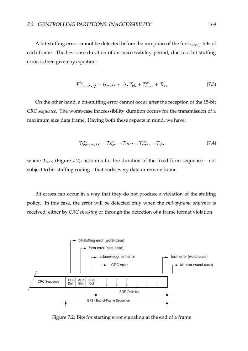
7.3. CONTROLLING PARTITIONS: INACCESSIBILITY 169
A bit-stuffing error cannot be detected before the reception of the first A BCDFEHGHG bits of
each frame. The best-case duration of an inaccessibility period, due to a bit-stuffing
error, is then given by equation:
ª � í� , �8��BCDFEHGHG � J(A B4DFEHGIG � �ML � ª �V�-D ��ª � íw4u(u'Ñ%u ��ª �FGHB (7.3)
On the other hand, a bit-stuffing error cannot occur after the reception of the 15-bit
CRC sequence. The worst-case inaccessibility duration occurs for the transmission of a
maximum size data frame. Having both these aspects in mind, we have:
ª h í� , �:��B4DFEHGIG � ª h í} �sDO� � ª*�!m!Õr��ª h íwCu(uPÑ8u ��ª �mGIB (7.4)
where ª*�!m!Õ (Figure 7.2), accounts for the duration of the fixed form sequence – not
subject to bit-stuffing coding – that ends every data or remote frame.
Bit errors can occur in a way that they do not produce a violation of the stuffing
policy. In this case, the error will be detected only when the end-of-frame sequence is
received, either by CRC checking or through the detection of a frame format violation.
CRC Sequence CRCDel
ACKSlot
ACK Del
bit error (worst-case)
form error (worst-case)
form error (best-case)
bit-stuffing error (worst-case)
acknowledgment error
CRC error
EOF Delimiter
EFS - End-of-Frame Sequence
Figure 7.2: Bits for starting error signaling at the end of a frame

170 CHAPTER 7. SECURING REAL-TIME PROPERTIES
CRC ERRORS
We discuss now, the actions to be performed by a node upon CRC checking. After
the reception of the 15-bit CRC sequence, a node should do one of two things, depending
on whether the CRC was good:
� if the CRC is correct, the node is obliged to change the bus level from recessive
to dominant, during the acknowledgment slot;
� otherwise, the node does not modify the value of the acknowledgment slot, and
signals the CRC error through the transmission of an error frame, that starts
immediately after the acknowledgment delimiter (Figure 7.2).
The corresponding inaccessibility time is generically given by expression:
ªX� , �8� í u í � ª } �'DO� � ª � ¨ m ��ª w4u(u'Ñ8u � ªn�FGHB (7.5)
where ª�� ¨ m represents the duration of the end-of-frame delimiter. The best and worst-
case bounds of equation (7.5) are obtained considering the shortest and the longest data
and error frames.
ACKNOWLEDGMENT ERRORS
Whenever a transmitter does not monitor a dominant level on the bus during the
acknowledgment slot, it interprets that as an error, and the transmission of an error frame
is started at the next bit (Figure 7.2). So, the duration of the corresponding network
inaccessibility period is generically given by equation:
ª � , �8��� í �r� ª7} �sDO� � ª*�!m!Õ���R � ª �V�-D ��ª7w4u(u'Ñ%up� ª �FGHB (7.6)
The best and worst-case inaccessibility bounds are obtained as usual, i.e. consider-
ing the minimum and the maximum durations for data and error frames.

7.3. CONTROLLING PARTITIONS: INACCESSIBILITY 171
In the presence of multiple errors, it may happen the transmitter monitors a faulty
dominant level, at the acknowledgment slot. The transmitter cannot detect such an error.
However, the lack of success in the transfer of the frame is signaled by the recipients
that having detected a CRC error issue a negative acknowledgment, in the form of an
error frame, immediately after the acknowledgment delimiter.
FORM ERRORS
All the frames used by the CAN protocol obey to a few pre-defined formats. Data
and remote frames have a fixed form end-sequence, where:
� the CRC delimiter and the acknowledgment delimiter, should always exhibit
recessive values;
� the end-of-frame delimiter, consists of seven consecutive recessive bits.
An error in the frame ending sequence implies the transmission of an error frame.
In the best-case, a form error occurs while receiving the CRC delimiter of a minimum
size data frame. The corresponding inaccessibility time is given by:
ª � í� , �:��G Ñ8ua� � ª � í} �sDO� � ª0��m�Õ���ª �V�3D � ª � íwCu>u'Ñ8u ��ª �FGHB (7.7)
The longest period of inaccessibility caused by a form error is when it occurs while
receiving the last but one bit of the end-of-frame delimiter, because a receiver monitoring
a dominant level at the last bit of this delimiter does not take that as a form error � . The
worst-case expression relates to the maximum size data and error frames:
ª h í� , �8��G Ñ8u]� � ª h í} �sDO� � ª �V�-D ��ª h íw4u(u'Ñ%u � ª �FGHB (7.8)
�As we will see ahead, this will be considered an early reactive overload error.

172 CHAPTER 7. SECURING REAL-TIME PROPERTIES
REQUESTED OVERLOAD
After a frame transfer, a node needs to wait for a given bus idle period before it is
allowed to initiate the transmission of other data/remote frame. The nominal duration
of this period � , is three bit-times (cf. Section 3.2, page 60).
However, the CAN specification allows a LLC sub-layer entity to increase the period
between consecutive data/remote frame transmissions, whenever it is not ready to
receive those frames. That is achieved on a frame-by-frame basis, by issuing a special
packet, known in CAN as LLC-requested overload frame. Though no currently available
commercial CAN controller implements such a feature, we examine the situation.
The transmission of a LLC-requested overload frame can only be started at the first bit
of the expected intermission (Figure 7.3) and, at most, two overload frame transmissions
may be consecutively requested. The best and worst-case inaccessibility times are
simply given by:
ª � í� , �:� Ñ � Ñ � } � ª � íÑ � Ñ � } (7.9)
ª h í� , �:� Ñ � Ñ � } � R � ª h íÑ � Ñ � } (7.10)
reactive overload (late, i.e. worst-case)
reactive overload (early, i.e. best-case)
data/remote frame
requested overload
nominal intermission
{EOF Delimiter
Figure 7.3: Bits for starting overload signaling
�Known in CAN terminology as intermission.

7.3. CONTROLLING PARTITIONS: INACCESSIBILITY 173
REACTIVE OVERLOAD ERRORS
The CAN specification obliges each data/remote frame transmission to be preceded
by a minimum bus idle period (cf. Section 3.2, page 60). To be in conformity with the
standard specification a CAN controller must react to the violation of this protocol
rule: whenever a dominant bit is detected at the last bit of the end-of-frame delimiter
(early overload) or at the first/second bit of the intermission (simple/late overload), the
transmission of a reactive overload frame is initiated one bit after the detection � .The best-case inaccessibility bound assumes the transmission of a single reactive
overload frame is initiated at the first bit of the expected intermission (Figure 7.3):
ª � í� , �:� u � Ñ � } � ª � íÑ � Ñ � } (7.11)
On the other hand, the transmission of a reactive overload frame is started, at the
latest, at the third bit of the expected intermission (Figure 7.3). The corresponding
worst-case inaccessibility duration is given by:
ª h í� , �:� u � Ñ � } � R � ª �V�3D � ª h íÑ � Ñ � } (7.12)
OVERLOAD FORM ERRORS
The CAN specification defines the same format for the LLC-requested and reactive
overload frames. A violation in the format of any of those frames triggers, according
to CAN specification 2.0B, an error/overload signaling process at the next bit slot.
An error signaling process is initiated when the frame format violation is detected
up to the last but one bit of the overload frame. The corresponding error counters are
�This description is in conformity with CAN specification 2.0 Part B (BOSCH, 1991). Our previous
studies of CAN inaccessibility (Rufino & Verıssimo, 1995; Rufino & Verıssimo, 1997; Verıssimo, Rufino& Ming, 1997) have assumed CAN 2.0A operation. The differences between the two analysis concerndetails that do not significantly affect the corresponding inaccessibility results (cf. Table 7.1, page 184).!
A short description of the overload signaling process and of the resulting format of overload framesis provided in Appendix B.3. Further details can be found in (BOSCH, 1991; ISO, 1993).

174 CHAPTER 7. SECURING REAL-TIME PROPERTIES
updated. The best-case duration of such an inaccessibility period is given by:
ª � í� , �:��GH� Ñ � } � ª �V�-D ��ª � íw4u(u'Ñ%u (7.13)
Conversely, when the frame format violation is detected only at the last bit of the
overload frame, it is initiated an overload signaling process. The error counts are not
incremented. To obtain the worst-case inaccessibility bound, it is assumed that two
LLC-requested overload frames are consecutively transmitted and the error occurs only
at the last bit of the second overload frame:
ª h í� , �8��GI� Ñ � } � ª h í� , �8� Ñ � Ñ � } � ª h íÑ � Ñ � } (7.14)
INCONSISTENT OVERLOAD ERRORS
Let us now consider that a subset " of the nodes detect, correctly or erroneously, a
dominant level in the second bit of the intermission. Those nodes initiate, at the next bit
slot, the transmission of a reactive overload frame (Figure 7.3). However, this action is
perceived in a different manner by the set of nodes that did not monitor the intermission
violation: those nodes interpret the first of the six dominant bits that made up the
overload flag as a start-of-frame delimiter. The sixth dominant bit violates the bit-stuffing
rule and causes the signaling of an error condition. Under these circumstances, the
corresponding inaccessibility period does not last more than:
ª � í� , �:���F� Ñ � } � R � ª �V�-D � J(A B4DFEHGIG � �<L � ª �V�3D � ª � íwCu>u'Ñ8u� A B4DKEHGHG � ª �V�-D ��ª � íw4u(u'Ñ8u � ª �FGHB (7.15)
In a less favorable fault scenario, some bits within the overload frame may also
get corrupted. As a consequence, there are no guarantees bit-stuffing monitoring may
#This subset may be restricted to a single node.

7.3. CONTROLLING PARTITIONS: INACCESSIBILITY 175
detect the error immediately. In any case, the error condition will be detected by one
of the other CAN error detection mechanisms, ultimately by CRC checking. To derive
the worst-case inaccessibility period due to an inconsistent overload signaling process,
we assume the inconsistency in intermission monitoring occurs only after the extension
of the interframe space through two consecutive LLC-requested overload frames:
ª h í� , �:���F� Ñ � } � R � ª h íÑ � Ñ � } ��R � ª �V�3D � ª h í} �sDO� � ª*� ¨ m���ª h íw4u(u'Ñ%u� R � ª h íÑ � Ñ � } � ª!�V�-D7��ª h í} �'DV� � ª � ¨ m � ª h íw4u(u'Ñ8u � ªn�FGHB� ª h í� , �:� Ñ � Ñ � } � ª �V�-D ��ª h í� , �:� í u í (7.16)
BIT ERROR BURST
Network errors may have many origins: mechanical defects in a cable or connector;
electromagnetic interference; loss of synchrony in a receiver circuitry, etc. Sometimes
these errors occur in bursts. In order to cope with error bursts, we extend our single-error
analysis to a multiple-error one.
data frame error frame intermission
d bitse
error burst Correct bit
Incorrect bit
Figure 7.4: Example of a bit error burst disturbance
Let us assume a given data stream is corrupted by multiple bit errors (as exempli-
fied in Figure 7.4) in a way that: only a single transmission of a data/remote frame is
corrupted; not all the bits inside the error burst disturbance necessarily exhibit an incor-
rect value; error signaling does not succeed while the disturbance lasts. In conformity
with the approach taken in (Charzinski, 1994), let us define:
Ö ÓZw - as the distance (measured in bits) between the first and the last incorrect
bit in a given bit error burst (Figure 7.4).

176 CHAPTER 7. SECURING REAL-TIME PROPERTIES
In the analysis of the worst-case scenario, we consider the first error occurs only at
the last bit of a maximum size data frame. The length of the bit error burst is given by Ó7wand the end of this disturbance is signaled through the transmission of an error frame
with a maximum size. The worst-case inaccessibility period due to a single burst of
errors is then given by:
ª h í� , �8��B¸�VE u BCD � ª h í} �'DO� � ª!�V�-D7��Ó w � ª!�V�-D7��ª h íw4u(u'Ñ8u ��ªX�FGIB� ª h í} �'DO� �Ô× h í � ª h íwCu(uPÑ8u ��ª �mGIB (7.17)
where, × h í accounts for the relative duration of the bursty error period with regard to a
reference value that we have made equal to the maximum duration of an error frame.
The value of × h í , the error burst length factor in a worst-case scenario, is then given by:
× h í � � � J(ÓZw � �ML � ª �V�-Dª h íwCu(uPÑ8u (7.18)
In the presence of a single error, Ó�w � �bit and therefore we have × h í � �
. For a burst
of errors, affecting the transmission of a particular data/remote frame, × h í � �. The
value of the × h í upper bound depends of the maximum bit error burst distance.
For transient errors the study presented in (Charzinski, 1994) uses an upper bound
value of Ó°w � R � bits. This is a very conservative value, higher than the bit error burst
distance of Ó°w � � ® bits considered in the standard documentation (BOSCH, 1991), a
value which is commonly used in other analysis of CAN error characteristics (Tran,
1999). The value of Ó°w for several CAN node permanent failures is established ahead.
On the other hand, to obtain the best-case inaccessibility bound due to a single burst
of errors we assume the first error, within a burst of length Ónw , occurs while transmitting
the start-of-frame delimiter:

7.3. CONTROLLING PARTITIONS: INACCESSIBILITY 177
ª � í� , �8��B¸�VE u BCD � ÓZw � ª �V�-D � ª � íw4u(u'Ñ8u ��ª �mGIB� ª �V�-D �Ô× � í � ª � íw4u(u'Ñ8u � ª �FGHB (7.19)
where, × � í accounts for the relative duration of the bursty error period with regard to
a reference value that we have now made equal to the minimum duration of an error
frame. The value of ×C� í is then given by:
× � í � � � J(ÓZw � �<L � ª �V�3Dª � íwCu(uPÑ8u (7.20)
The result provided by equation (7.19) is slightly pessimistic, in the sense that in a
best-case scenario, the transmission of the error frame flag may partially coincide with
the error burst period.
MULTIPLE ERROR BURSTS
We now consider a scenario where multiple bursts of errors affect different trans-
missions of data/remote frames, i.e. we consider the occurrence of multiple omission
failures. By assumption (cf. Section 4.2) all the errors have its origin in one single
component. Moreover, we assume the different error bursts do affect consecutive
transmissions of data/remote frames�%$
. The bounded omission degree assumption, for-
malized earlier in the MAC sub-layer properties (cf. Figure 4.6, page 82), provides the
grounds for bounding the total duration of one inaccessibility period with origin in
multiple bursts of errors: in a known time interval, no more than � data or remote frames are
corrupted by errors.
Therefore, the corresponding worst-case inaccessibility bound directly results from
the application of the bounded omission degree assumption, as formalized in the MAC
�%&Meaning, there are no good transmissions of data/remote frames between any two error bursts.
Only error signaling succeeds.

178 CHAPTER 7. SECURING REAL-TIME PROPERTIES
sub-layer property MCAN5, to the result provided by equation (7.17):
ª h í� , �:� � �VE u B4D � � � J8ª h í} �'DV� �Ô× h í � ª h íwCu>u'Ñ8u ��ª �FGIB L (7.21)
The bounded omission degree property MCAN5 describes CAN behavior with regard
to omission failures even when network omissions are successive, meaning they can
be interleaved with good data/remote frame transmissions�'�
. As a consequence, the
worst-case value for the total duration of all those successive inaccessibility periods,
within a known time interval, is also given by equation (7.21).
NODE PERMANENT FAILURES
So far, we have assumed CAN operation is disturbed only by the occurrence of
transient errors. In order to complete our analysis of CAN inaccessibility, we proceed
with the study of a few examples, where the occurrence of permanent node failures
is assumed. Those examples include: the study of CAN behavior in the presence of
stuck-at conditions; the analysis of the consequences of a CRC circuitry failure, both at
receiver and transmitter nodes.
DEAF RECEIVER
Let us assume the receiver of a given node fails and start to hear only recessive
symbols. When the node tries to perform the transmission of a frame an error occurs
at the first bit, because the node is unable to monitor the dominant value of the start-of-
frame delimiter. The transmission of the corresponding error frame does not succeed
either and a burst of dominant bits is sent by the node, before its transition to the error
passive state� � (BOSCH, 1991; ISO, 1993). Given the length of this burst can be known,
equation (7.19) can be used to obtain the best-case inaccessibility time:
�(�Such kind of errors may have its origin in a faulty transmitter.�%�The behavior of an error passive node is not compliant with the model of CAN defined in Chapter 4.
The impact on CAN inaccessibility of the corrective actions specified in Section 4.1 to secure a behaviorin conformity with the weak-fail-silent model, is discussed ahead.
7.3. CONTROLLING PARTITIONS: INACCESSIBILITY 179
ª � í� , �:� }'w �iG � ª �V�-D �Ô× � í � }'w �cG � ª � íw4u(u'Ñ8u � ª �FGHB (7.22)
where, × � í � }'w �cG is the corresponding error burst length factor. The result provided by
equation (7.22) takes into account that an error condition letting a node become error
passive causes the node to send an active error flag (BOSCH, 1991; ISO, 1993).
In addition, we consider the inaccessibility time upper bound due to a deaf receiver
failure can be obtained directly from equation (7.17), given the corresponding error
burst length factor, × h í � }'w �iG :ª h í� , �:� }'w �iG � ª h í} �sDO� �Ø×!h í � }'w �iG � ª h íwCu(uPÑ8u � ªn�FGHB (7.23)
The inaccessibility time specified by equation (7.23) is slightly higher than the real
worst-case duration of an inaccessibility period caused by a deaf receiver, because
expression (7.23) does not take into account that, in the absence of other errors, a stuck-
at-recessive failure occuring after the acknowledgment slot (Figure 7.2) can no longer be
detected in the current transmission.
The value of the Ó�w upper bound, to be used in the evaluation of the error burst
length factors related to a deaf receiver failure, is given by expression:
ÓZw � }'w �iG�� � �ÚÙ �/ M � DON } � ~u(vHw4u �~¬u(vHwCu G Û (7.24)
where ÜØÝ represents the ceiling function� � . This expression is obtained assuming that
the error occurs while a frame is being received and accounts for the total number of
consecutive dominant bits transmitted by the defective node, before it enters the error
passive state. This includes: the original error in the monitoring of a dominant bit
value (e.g. at the acknowledgment slot); the subsequent errors in the issuing of an active
error flag. According to the CAN fault confinement mechanisms, specified in (BOSCH,
1991; ISO, 1993) and summarized in Section 3.3 (page 64), the Receive Error Count is
�4�The ceiling function Þ'ßyà is defined as the smallest integer not smaller than ß .

180 CHAPTER 7. SECURING REAL-TIME PROPERTIES
increased: ~u(vHw4u � , upon the occurrence of the first bit error; ~Su>vHwCu G , for each error in the
error signaling process. The node enters the error passive state, when the Receive Error
Count equals or exceeds�/ < � DON } , the error active count threshold.
STUCK-AT-DOMINANT FAILURES
Let us now assume the receiver/transmitter circuitry of a given node fails and starts
receiving/transmitting only dominant symbols. A stuck-at-dominant receiver failure
exhibits a moderate level of severity. A node with this kind of failure stops to disturb
bus operation when it enters the error passive state. The bit error burst distance ( Ó7w )related to a stuck-at-dominant receiver failure is given by:
Ó w ��B4DFE í �:R u(v S � R � A4BCDO� } � J>A4BCDO� } � �ML � Ù �/ M � DON } � J(~¬u(vHwCu � �é~u(vHw4u � �é~u(vHw4u'} L~u(vHw4u'} Û (7.25)
where: A BCDO� } represents the length of the sequence of consecutive dominant bits, tol-
erated by the CAN fault confinement mechanisms after the transmission of an active
error flag. The specification of CAN fault confinement mechanisms in (BOSCH, 1991;
ISO, 1993) implies the application of a set of independent rules in the increment of the
Receive Error Count (cf. Figure 3.14, page 65).
During an initial sequence of R � A BCDO� } consecutive dominant bits, the Receive Error
Count is increased (cf. Figure 7.5): ~Su>vHwCu � , upon the detection of the error by the receiver;
~¬u(vHwCu � , one bit after the transmission of the corresponding error flag; ~�u(vHwCuP} , at the end
of the R � A B4DO� } sequence of consecutive dominant bits. For each additional sequence of
A B4DV� }@� � consecutive dominant bits, the Receive Error Count is increased ~�u(vHw4u'} . The node
enters the error passive state when the Receive Error Count equals or exceeds�/ M � DON } , the
error active count threshold.
Conversely, a node exhibiting a stuck-at-dominant transmitter severely disturbs
CAN operation, because such a failure completely destroys any kind of bus activity,
error signaling included. At this point, we assume a node with a stuck-at-dominant

7.3. CONTROLLING PARTITIONS: INACCESSIBILITY 181
TEC
stk_dl stk_dl +1stk_dl +1stk_dl
txerdtxerr txerd txerd
REC
rxerd rxerd rxerdrxer2rxer1
error detection (worst-case) error flag
stuck-at-dominant stream
Figure 7.5: Updating Receive/Transmit Error Counts upon stuck-at-dominant failures
transmitter only stops to interfere in network operation when it enters the bus off state� � .
The CAN fault confinement mechanisms record the occurrence of transmission errors in
a Transmit Error Count (cf. Figure 3.14, page 65). The corresponding update procedure is
illustrated in Figure 7.5: the Transmit Error Count is increased ~ D vHw4u(u upon the detection
of the error and ~ D vHw4u'} , at the end of the initial sequence of R � A B4DO� } consecutive dominant
bits; the Transmit Error Count is increased ~ D vHwCu'} , for each additional sequence of A B4DO� }s� �consecutive dominant bits. The value of ÓXw to be used in computing the error burst
length factors of a stuck-at-dominant transmitter failure, is thus:
Ó w ��B4DFE í �:R3D v S � R � A4B4DO� } �¯J(A4B4DO� } � �<L � Ù �/ M � Ñ GHG � J(~ D vHw4u(u���~ D vHw4u'} L~ D vHw4u'} Û (7.26)
where,�/ < � Ñ GHG is the bus off state count threshold.
The best and worst-case inaccessibility times can be derived directly from equations
(7.19) and (7.17), respectively. The expressions derived are common to receiver and
transmitter failures, given the corresponding error burst length factors:
ª � í� , �8��BCDFE í � � ª �V�-D �Ô× � í ��BCDFE í � � ª � íw4u(u'Ñ8u � ª �FGHB (7.27)
ª h í� , �:��B4DFE í � � ª h í} �sDO� �Ø× h í ��B4DFE í � � ª h íw4u(u'Ñ8u � ª �FGHB (7.28)
�4�A node in the bus off state is not allowed to have any influence on the bus (BOSCH, 1991; ISO, 1993).
This attribute can be secured by disabling the medium interface driver circuitry (cf. á 6.3, page 147).

182 CHAPTER 7. SECURING REAL-TIME PROPERTIES
RECEIVER FAILURE
Let us now assume the CRC checker of an error active node receiver fails, starting
to report an error for every data/remote frame it receives� � . Since no transmission
of a data/remote frame succeeds while the defective node is in the error active state,
omission failures are consecutive in the network. In the absence of other errors, each
data/remote frame omission is followed by a successful transmission of an error frame,
being × h í � �. This faulty behavior subsists until the defective node enters the error
passive state, which only happens after the occurrence of a number of data/remote
frame omissions, given by:
�u(v GH�s�F�n�ãâ �/ M � DON }~ u(vHw4u � �é~ u(vHw4u ��ä (7.29)
where the terms under the fraction represent two different contributions from the CAN
fault confinement mechanisms to the increase of the Receive Error Count (cf. Figure 3.14,
page 65). They derive from the application of more than one error counting rule to the
same data/remote frame transfer, as specified in (BOSCH, 1991; ISO, 1993).
The worst-case inaccessibility time of the network due to the failure of a receiver is
thus obtained applying expression (7.29) to equation (7.21), given × h í � �. Thus:
ª h í� , �:� u>v GI�'�F� � � u(v GI�'�F� � J%ª h í} �sDO� ��ª h íw4u(u'Ñ8u ��ªX�FGIB L (7.30)
TRANSMITTER FAILURE
A malfunction in the CRC generator of an error active transmitter produces a similar
faulty behavior. However, the omission failures are, in general, successive in the
network. The only exception occurs if the failed node is transmitting the message with
the lowest identifier in the system. In any case, the return to a normal bus operation
�%�In (Rufino et al., 1999a), we study how the use of some simple self-checking mechanisms may
improve the detection of node permanent failures, CRC circuitry included. Most of the existing CANcontrollers do not provide such features. One exception is the simplified CRC checking scheme of owntransmissions, implemented in the Siemens 81C90/91 family (Siemens, 1995b).

7.3. CONTROLLING PARTITIONS: INACCESSIBILITY 183
does not occur until the defective node becomes error passive. The number of omission
failures causing this transition is bounded by the following expression:
� D v GI�'�F��� â �/ M � DON }~ D vHwCu(u ä (7.31)
where, ~ D vHw4u(u is the Transmit Error Count increment produced by each transmission error
(BOSCH, 1991; ISO, 1993).
The longest period of inaccessibility period due to a transmitter failure is then
obtained applying expression (7.31) to equation (7.21), being × h í � �. Therefore:
ª h í� , �8��D v GI�'�F� � � D v GH�s�m� � J%ª h í} �sDO� � ª h íwCu>u'Ñ8u ��ª �FGIB L (7.32)
Analytic results
For consolidation of our study regarding accessibility constraints we now evaluate
the inaccessibility time bounds, for a given CAN application, for example, a 32 node
CAN fieldbus for real-time sensing and actuating, in an industrial environment. We
assume conservative bounds for the omission degree ( � � � ³ ) and for the bit burst error
distance ( Ó w � R � ), due to medium errors. The standard values of the CAN protocol
parameters are listed next:Ò bit-stuffing width: g B4DFEHGIG ç»å ;Ò stuck-at-dominant error tolerance width: g BCDO� }�ç»æ ;Ò error active count threshold: çHææ/� DON } ç yèMz ;Ò bus off count threshold: çHææ � Ñ GIG ç è å�é ;Ò Receiver Error Count increment (all errors): t�u(vHw4u � ç y ;Ò Receiver Error Count increment (local errors): t�u(vHw4u � ç z ;Ò Receiver Error Count increment (error/overload flag errors): t u(vHw4u G]ç z ;Ò Receiver Error Count increment (stuck-at-dominant errors): t�u>vHwCu'} ç z ;Ò Transmitter Error Count increment (all errors): t D vHw4u(u ç z .Ò Transmitter Error Count increment (stuck-at-dominant errors): t D vHw4u'}Èç z .
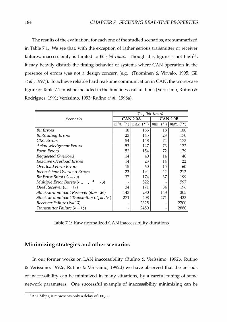
184 CHAPTER 7. SECURING REAL-TIME PROPERTIES
The results of the evaluation, for each one of the studied scenarios, are summarized
in Table 7.1. We see that, with the exception of rather serious transmitter or receiver
failures, inaccessibility is limited to µ �� bit-times. Though this figure is not high� � ,
it may heavily disturb the timing behavior of systems where CAN operation in the
presence of errors was not a design concern (e.g. (Tuominen & Virvalo, 1995; Gil
et al., 1997)). To achieve reliable hard real-time communication in CAN, the worst-case
figure of Table 7.1 must be included in the timeliness calculations (Verıssimo, Rufino &
Rodrigues, 1991; Verıssimo, 1993; Rufino et al., 1998a).
Ó � , � (bit-times)Scenario CAN 2.0A CAN 2.0B
min. ( � í ) max. ( h í ) min. ( � í ) max. ( h í )Bit Errors 18 155 18 180Bit-Stuffing Errors 23 145 23 170CRC Errors 54 148 74 173Acknowledgment Errors 53 147 73 172Form Errors 52 154 72 179Requested Overload 14 40 14 40Reactive Overload Errors 14 23 14 22Overload Form Errors 15 60 15 60Inconsistent Overload Errors 23 194 22 212Bit Error Burst ( ÆÃwMç è�ê ) 37 174 37 199Multiple Error Bursts ( ò � çìë , Æ w ç è�ê ) - 522 - 597Deaf Receiver ( Æw<ç y æ ) 34 171 34 196Stuck-at-dominant Receiver ( ÆZwMç yè é ) 143 280 143 305Stuck-at-dominant Transmitter ( ÆZw�ç è å;í ) 271 408 271 433Receiver Failure ( òèç y å ) - 2325 - 2700Transmitter Failure ( òèç y é ) - 2480 - 2880
Table 7.1: Raw normalized CAN inaccessibility durations
Minimizing strategies and other scenarios
In our former works on LAN inaccessibility (Rufino & Verıssimo, 1992b; Rufino
& Verıssimo, 1992c; Rufino & Verıssimo, 1992d) we have observed that the periods
of inaccessibility can be minimized in many situations, by a careful tuning of some
network parameters. One successful example of inaccessibility minimizing can be
�%�At 1 Mbps, it represents only a delay of qH:H: ÿ�� .

7.3. CONTROLLING PARTITIONS: INACCESSIBILITY 185
found in (Rufino & Verıssimo, 1992a), where for the ISO 8802/4 Token-bus we had
managed a five-fold decrease in the worst-case inaccessibility figure.
As a general rule, CAN inaccessibility has very little sensitivity to network parame-
ter tuning. However, one can define a minimizing strategy aiming to reduce the periods
of CAN inaccessibility upon the permanent failure of a node. An effective strategy,
based on the early detection of node permanent failures, will hopefully be feasible
on top of modern CAN controllers, supporting on-line access to the Transmit/Receive
Error Counts (Philips, 1997a; Motorola, 1998). The analysis of these counts upon the
occurrence of each error should allow to distinguish the failure of the local node from
the failures of other nodes in the system (Rufino et al., 1999a).
An alternative solution exploits the mechanisms available in most of the existing
CAN controllers (e.g. (Intel, 1995)). The technique is based on the issuing of a warning
signal by the CAN controller if any error count exceeds a given threshold (BOSCH,
1991; ISO, 1993). This warning signal is used to force the node to enter the bus off state.
The application of this technique has been specified in Section 4.1.1, as a fault-tolerance
measure, to avoid the sources of inconsistency due to the erratic behavior of error passive
nodes. Next, we analyze the effectiveness of this policy with regard to the reduction
of the longest periods of inaccessibility. The CAN specification in (BOSCH, 1991; ISO,
1993) sets the threshold of the warning signal to�/ M hXGHBä� ´µ . A node exhibiting a
permanent failure stops to interfere in network operation when the Transmit/Receive
Error Count equals or exceeds�/ M hnGHB .
DEAF RECEIVER
The best and worst-case inaccessibility times due to a deaf receiver failure are given
by equations (7.22) and (7.23), respectively. However, the value of Ó�w to be used in the
evaluation of burst error length factors is now given by:
ÓZw � í }'w �cG� � �ÚÙ �/ M hXGIB � ~ u(vHw4u �~u>vHwCu G Û (7.33)

186 CHAPTER 7. SECURING REAL-TIME PROPERTIES
STUCK-AT-DOMINANT FAILURES
A similar method is used in equations (7.34) and (7.35), in the definition of the
bit error burst distance ( Ó�w ) concerning, respectively, stuck-at-dominant receiver and
transmitter failures.
Ó w � í B4DFE í �:R u(v S � R � A BCDO� }È� J>A BCDO� }È� �ML � Ù �/ M hXGIB � J>~u(vHw4u � �é~u(vHw4u � �é~u(vHw4u'} L~¬u(vHw4u'} Û (7.34)
Ó w � í BCDFE í �:R3D v S � R � A4B4DO� } � J(A4B4DO� } � �<L � Ù �/ M hnGHB � J>~ D vHw4u(uÈ��~ D vHwCuP} L~ D vHwCuP} Û (7.35)
The results of equations (7.34) and (7.35) assume that the mechanisms detecting the
pre-specified number of receive/transmit errors (i.e. omission errors), after which the
node will be shut-down, are provided by the built-in fault confinement functions of the
standard CAN protocol.
However, in Section 6.3 (page 147), we have introduced a dedicated Channel moni-
toring function intended to provide an early detection of stuck-at-dominant transmitter
failures. The idea is to control the length of the sequence of consecutive dominant bits
transmitted by a node, as illustrated in Figure 7.6, taking into account the discrete
values defined by equations (7.26) and (7.35).
stuck-at-dominant Rx signal
stuck-at-dominant Tx signalstk_d2 . l +1stk_dl +1stk_dl
TEC
txerdtxerr txerd
transmit-error-tolerance margin
REC
rxerd rxerd rxerdrxer2rxer1
receive-error-tolerance marginerror occurrence
Figure 7.6: Transmit/receive error-tolerance margins
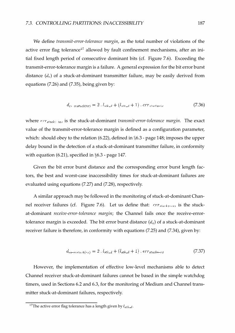
7.3. CONTROLLING PARTITIONS: INACCESSIBILITY 187
We define transmit-error-tolerance margin, as the total number of violations of the
active error flag tolerance� � allowed by fault confinement mechanisms, after an ini-
tial fixed length period of consecutive dominant bits (cf. Figure 7.6). Exceeding the
transmit-error-tolerance margin is a failure. A general expression for the bit error burst
distance ( Ó w ) of a stuck-at-dominant transmitter failure, may be easily derived from
equations (7.26) and (7.35), being given by:
Ó w � � BCDFE í �:R3D v S � R � A B4DO� }È� J(A B4DO� }È� �<L � �/ M BCDFE í �8��D v (7.36)
where�/ M B4DFE í �:��D v , is the stuck-at-dominant transmit-error-tolerance margin. The exact
value of the transmit-error-tolerance margin is defined as a configuration parameter,
which: should obey to the relation (6.22), defined in ÷ 6.3 - page 148; imposes the upper
delay bound in the detection of a stuck-at-dominant transmitter failure, in conformity
with equation (6.21), specified in ÷ 6.3 - page 147.
Given the bit error burst distance and the corresponding error burst length fac-
tors, the best and worst-case inaccessibility times for stuck-at-dominant failures are
evaluated using equations (7.27) and (7.28), respectively.
A similar approach may be followed in the monitoring of stuck-at-dominant Chan-
nel receiver failures (cf. Figure 7.6). Let us define that:� M B4DFE í �:� u(v , is the stuck-
at-dominant receive-error-tolerance margin; the Channel fails once the receive-error-
tolerance margin is exceeded. The bit error burst distance ( Ó w ) of a stuck-at-dominant
receiver failure is therefore, in conformity with equations (7.25) and (7.34), given by:
Ó w � � B4DFE í �:R u>v S � R � A B4DO� }È� J(A B4DO� }È� �<L � �/ M BCDFE í �8� u(v (7.37)
However, the implementation of effective low-level mechanisms able to detect
Channel receiver stuck-at-dominant failures cannot be based in the simple watchdog
timers, used in Sections 6.2 and 6.3, for the monitoring of Medium and Channel trans-
mitter stuck-at-dominant failures, respectively.
� �The active error flag tolerance has a length given by TV^4_K� � .

188 CHAPTER 7. SECURING REAL-TIME PROPERTIES
One reason is that, the stuck-at-dominant Channel receiver failure may be internal
to the CAN controller itself. Without specialized mechanisms, one have to resort to the
native CAN fault confinement mechanisms, to detect the failure (Rufino et al., 1999a):
as specified in equation (7.34); possibly, using the Receive Error Count value available
on-line in some CAN controllers (Philips, 1997a; Motorola, 1998).
RECEIVER FAILURE
We now consolidate the inaccessibility parameters related with receiver permanent
failures manifesting their effects as CRC errors:
� í u(v GH�s�m� � â �/ M hXGIB~¬u(vHw4u � ��~¬u(vHw4u � ä (7.38)
ª h í� , �:� í u>v GI�'�F� � � í u(v GI�'�F� � J%ª h í} �sDO� ��ª h íw4u(u'Ñ8u ��ª �FGIB L (7.39)
TRANSMITTER FAILURE
Similar expressions are derived for transmitter permanent failures causing CRC
errors:
� í D v GI�'�F��� â �/ M hnGHB~ D vHwCu>u ä (7.40)
ª h í� , �8� í D v GI�'�F� � � í D v GH�s�m� � J8ª h í} �'DO� � ª h íwCu>u'Ñ8u ��ª �FGHB L (7.41)
BUS RECONFIGURATION
We discuss next the inaccessibility scenario that results from the occurrence of
stuck-at-dominant failures in the bus physical layer. Resilience to those failures has
to be provided by special fault-tolerance mechanisms, such as the media redundancy

7.3. CONTROLLING PARTITIONS: INACCESSIBILITY 189
mechanisms discussed in Section 6.2. The inaccessibility period associated with bus
reconfiguration in the presence of stuck-at-dominant medium failures is analyzed.
Let us denote by ª BCDFE í �:� }a� the detection latency of a stuck-at-dominant medium
failure, as specified by equation (6.3), page 138. The duration of corresponding inac-
cessibility period accounts for two different contributions: the time required to detect
the error and the time needed for recovery. Under a slightly pessimistic approach,
we consider the recovery process includes the transmission of a complete error frame,
despite the resume of normal bus operation requires only the signaling of the error
frame ending delimiter. The best-case inaccessibility time is then given by equation:
ª � í� , �8�#�VEHB � ª7B4DKE í �8� }a� � ª � íwCu>u'Ñ8u ��ªn�FGHB� ª �V�-D �Ô× � í �#�VEHB � ª � íw4u(u'Ñ8u ��ª �FGIB (7.42)
To obtain the corresponding worst-case inaccessibility time we consider the
medium failure occurs while transmitting the last bit of a maximum size data frame:
ª h í� , �8�#�VEHB � ª h í} �'DV� � ª �V�-D ��ª BCDFE í �:� }a����ª h íw4u(u'Ñ%u ��ª �FGHB� ª h í} �'DV� �Ô× h í �#�VEHB � ª h íw4u(u'Ñ8u ��ª �mGIB (7.43)
The corresponding burst error length factors result from a value of Ónw obtained in
conformity with equation (6.3), page 138:
ÓZw �#�VEHB � R � A BCDO� }È� J>A BCDO� }È� �ML � � M B4DFE í �:� u(v RY�VEHB S (7.44)
where,�/ < B4DKE í �8� u(v RW�VEHB S is the receive-error-tolerance margin associated to a Medium stuck-
at-dominant receiver failure and represents the total number of allowed violations, but
the first, of the active error flag tolerance.

190 CHAPTER 7. SECURING REAL-TIME PROPERTIES
Consolidated analytic results
We now consolidate the values of the CAN inaccessibility bounds with regard to
the occurrence of permanent failures. The parameters provided by expressions (7.33)
up to (7.44) are used in this evaluation. The results are summarized in Table 7.2. The
following values – obeying to the relation (6.22), page 148 – are used as error-tolerance
margins:Ò stuck-at-dominant transmit-error-tolerance margin: çIæ/æ B4DKE í �8��D v·ç y ;Ò stuck-at-dominant receive-error-tolerance margin (Medium): çHææ B4DFE í �:� u(v RY�VEHB S ç è ;Ò standard stuck-at receive-error-tolerance margin (warning threshold): çHææ BCDFE í �:� u>v7ç yê .
The value of the standard stuck-at receive-error-tolerance margin is obtained con-
sidering the threshold of�/ < hXGHB � ´�µ , for the issuing of a warning signal by the CAN
controller (BOSCH, 1991).
Ó � , � (bit-times)Scenario CAN 2.0A CAN 2.0B
min. ( � í ) max. ( h í ) min. ( � í ) max. ( h í )Deaf Receiver ( Æw<ç y ë ) 30 167 30 192Stuck-at-dominant Receiver ( ÆZwMçìî;í ) 111 248 111 273Stuck-at-dominant Tx-confinement ( ÆÃw<çìî;í ) 111 248 111 273Stuck-at-dominant Tx-monitoring ( Æ w ç è�è ) 39 176 39 201Receiver Failure ( òèç yMy ) - 1705 - 1980Transmitter Failure ( òèç yè ) - 1860 - 2160Bus Reconfiguration ( Æ w çìë ê ) 47 184 47 209
Table 7.2: Reduced normalized CAN inaccessibility durations
As expected, the decrease achieved in the duration of the longest periods of inac-
cessibility is moderate. However, the reduction of CAN inaccessibility periods was not
the main reason for the application of a node shutting-down policy, upon the warning
the node has given a number of errors exceeding a pre-defined threshold. This policy
was introduced to secure a weak-fail-silent behavior (cf. Section 4.1.1).
On the other hand, notice the extremely low worst-case figure of bus reconfiguration
(209 û @ 1 Mbps), compared with the 100�
of the RED-CAN system (NOB, 1998).

7.3. CONTROLLING PARTITIONS: INACCESSIBILITY 191
7.3.2 Inaccessibility Control Methods
The study of CAN accessibility constraints presented in Section 7.3.1 constitutes a
crucial step for the control of CAN inaccessibility, in the sense it shows the bounded
nature of CAN inaccessibility events and establishes a comprehensive set of easy-to-use
formulas for the evaluation of those bounds.
The next step towards a reliable hard real-time operation of CAN concerns the
accommodation of the periods of inaccessibility in the timeliness model. This accom-
modation process needs to be extended to all the relevant levels of the system and it
implies that the timing specifications of each level have to be derived through a per-
formability analysis, rather than established by a model that only considers no-fault
scenarios (Verıssimo, Rufino & Ming, 1997).
The occurrence of periods of network inaccessibility must be considered: in the
calculation of the real worst-case message transmission delays, having in mind the
analysis of message network schedulability guarantees (Tindell & Burns, 1994a; Livani
et al., 1998); in the calculation of the real worst-case protocol execution times, e.g. for
real-time processing purposes; in the dimensioning of timeouts (Verıssimo, 1993).
Next, we analyze in detail the implications of inaccessibility on the operation of
a CAN-based real-time communication system. Let us consider a system only with
local clocks (timers), used to implement timeouts. Timeouts may be used in CAN
communications to detect timing, omission and crash failures in low-level protocols,
such as those described in Chapter 5. They can also be used by upper-layer protocols to
perform the surveillance of remote parties, upon waiting for the response to a request
(e.g. the invocation of a remote object).
Timeout values are set as a function of protocol execution times, which in general
include terms that depend on the protocol processing delays and on the worst-case
message transmission delay, Ü D } , observed at a given level of the system and defined
in MCAN7 (Figure 4.6 - page 82). Usually, protocol processing delays have values
much lower than Ü D } , and therefore they have a negligible influence in the timeliness
of remote interactions. If this condition does not hold, the protocol designer can be

192 CHAPTER 7. SECURING REAL-TIME PROPERTIES
given a consolidated Ü D } value, accounting for processing delays. Without loss of
generality� , we assume that Ü D } represents the optimum value for the delay associated
to the detection of a failure in a remote peer entity.
However, ÜQD } cannot be used in the low-level and upper-layer protocol timers
without special inaccessibility control measures, or else they could timeout too early
upon the occurrence of an inaccessibility period. This might lead to protocol failure.
For example, a timer expiring prematurely in the totally ordered CAN communication
protocol of Section 5.2.3, may cause a data message to be wrongly discarded because
the corresponding ACCEPT message is delayed in some queue by the occurrence of an
inaccessibility period.
According to MCAN6 (Figure 4.6, page 82), in a time interval of concern, Ü�u'} ,there may be at most Û periods of inaccessibility adding-up to at most Ü � , � . Let, Ü�uP}be the longest protocol execution duration. At this point, note that incorporating a
corrective term given by the inaccessibility duration worst-case bound (MCAN6), Ü � , � ,in the timeout values is a sufficient condition for running synchronous (hard real-time)
timeout-based protocols over a CAN infrastructure. However, timeouts do not have
anymore an optimum sizing. Furthermore, Ü � , � may be much greater than Ü D } , at least
at the low-levels of communication, causing the timeouts to be undesirably long. Long
timeouts unnecessarily increase the delay associated to the detection of a failure, in the
absence of inaccessibility.
As a consequence, a solution taking away the effects of CAN inaccessibility from the
timeout values would be much welcome. To the programmer it can be given a simple
and elegant abstraction of a distributed environment which is always connected, with
timers yielding optimal values with regard to the detection of failures.
A comprehensive set of mechanisms intended for the control of inaccessibility
in LAN-based protocols was discussed in (Verıssimo, Rufino & Rodrigues, 1991;
Verıssimo, 1993). We reanalyze the problem next, in the context of CAN.
�4!The utilization of such a simplified protocol model does not significantly influence the results of a
timeliness analysis. It simply aims to avoid the introduction of parameters not included in the model ofCAN defined in Section 4.2.

7.3. CONTROLLING PARTITIONS: INACCESSIBILITY 193
Are LAN-based solutions effective in CAN?
In LANs, and in most fieldbuses, there are no specific low-level mechanisms to
enforce message delivery upon the occurrence of network omissions. The definition of
a bounded omission degree assumption (Verıssimo & Marques, 1990), specifying that
no more than � omissions can occur in a time interval of reference, Ü u'} , provides the
foundation for the design of basic error processing protocols with bounded termination
times, crucial for the reliable real-time operation of the LAN or fieldbus.
Two general methods to handle network omissions in LANs, analyzed in
(Verıssimo, Rufino & Rodrigues, 1991), are summarized next. Tolerance to � omis-
sion faults can be achieved through a diffusion-based masking algorithm: the proto-
col systematically repeats a transmission ��� � times; no error-detecting timeouts are
used. Since the error rate in LANs is expected to be low, a more efficient solution,
for the average case, uses an error detection/recovery algorithm implemented through
transmission-with-reply rounds: after a transmission, replies from a number of recipi-
ents are awaited for; if some reply is missing, the data message is retransmitted upon
a given timeout period has elapsed.
The own properties of CAN should be exploited in the adaptation of those proto-
cols to a cost-effective operation in CAN-based infrastructures. Given diffusion-based
protocols do not use timeouts, the control of CAN inaccessibility may be simply based
on the implicit signaling of network accessibility, provided by the standard communi-
cation interface, when the transmission of a frame is confirmed. This technique was
used with success in the design of the EDCAN protocol (cf. ÷ 5.2.1). Next, we analyze
in detail how to control CAN inaccessibility in timeout-based protocols.
INACCESSIBILITY ADDITION
The simplest method to control the implications that the periods of inaccessibil-
ity may have in the operation of timeout-based protocols, transmission-with-reply
included, is to add to the timeout values set in function of Ü D } (MCAN7, Figure 4.6
- page 82), a corrective term, Ü � , � , defined in MCAN6 and accounting for the worst-

194 CHAPTER 7. SECURING REAL-TIME PROPERTIES
case duration of an inaccessibility incident. No further action is needed to tolerate
inaccessibility faults.
The engineering of such a method, which we call herein inaccessibility addition, is
extremely simple. The management of protocol timers (cf. Figure 4.10, page 89) can
be easily mapped into the service interface of a standard timer agency (ANSI/IEEE,
1993; Digital, 1996). For example, the incorporation of Ü � , � in the timeout values can
be made transparent to the programmer: upon the issuing of a request to start a timer,
the corresponding standard primitive is invoked with the extended timeout value.
The inaccessibility addition method did not proved effective in LANs, because in
such networks and in many fieldbuses, Ü � , � may have values much greater than Ü D } .For example, in an industrial setting of reference, using the ISO 8802/4 Token-bus
LAN or the PROFIBUS network, with a size of 32 nodes, ÜèD } is usually in the order of
a few tens of milliseconds (Rzehak et al., 1989; Tovar & Vasques, 1998a). On the other
hand: ÜQ� , � � � ² ���� , in a 5 Mbps ISO 8802/4 Token-bus (Rufino & Verıssimo, 1992b);
Ü � , �Q� ¶ ® � , in a 500 Kbps PROFIBUS (Verıssimo, Rufino & Ming, 1997). The situation
for CAN-based systems is analyzed ahead.
INACCESSIBILITY TRAPPING
An alternative way of incorporating the periods of inaccessibility in the operation of
timeout-based protocols was thoroughly discussed in (Verıssimo, Rufino & Rodrigues,
1991), for LAN-based infrastructures. Dubbed inaccessibility trapping in (Verıssimo,
1993), the method is based on the transformation of inaccessibility periods in omissions.
A standard MAC sub-layer communication interface is assumed.
Protocol timers, such as Ü hn�'�-D (7wL�ÈÑ D w in the diagram of Figure 7.7, do not include
Ü � , � , being set to the optimum timeout value Ü D } . A timer is started only after the
confirmation the transmission was issued, because that represents a signal the network
was accessible. Should the network be inaccessible, the confirmation does not come.
The protocol is prevented from proceeding and the timer start is postponed until the
network becomes accessible again (e.g. situations I1 or I4, in Figure 7.7).

7.3. CONTROLLING PARTITIONS: INACCESSIBILITY 195
t_outstart
(I2) (I3)(I1) (I4)
LAN Interface
User Interfacerequest
start
retry
Inaccessibility
waitRemoteT
Through the system layers
.req .cnf .cnf.req
~~ ~~ ~~ ~~
waitRemoteT
Figure 7.7: Timing of the LAN-based inaccessibility trapping method
This technique provides a basis to secure the correctness of protocol operation in the
presence of inaccessibility events, with timers yielding optimum timeout values. All
inaccessibility events occuring between two consecutive network accessibility signals
(e.g. situations I2, I3 or I4 in Figure 7.7) are transformed into one “omission”. In the
presence of omission and/or inaccessibility faults, a timer may expire and a recovery
process may have to be initiated. However, a protocol designed to take care of �omissions in the system, will keep working for �Q��Û “omissions”, being Û the maximum
number of inaccessibility occurrences (MCAN6, Figure 4.6 - page 82) during protocol
execution. The system programmer may then use a consolidated ï � �p�SÛ omission
bound figure.
Given the low-level transmission-with-reply protocol was used in former works
on LANs to build very efficient communication services (Rodrigues & Verıssimo, 1992;
Rodrigues, Verıssimo & Rufino, 1993), we take it as an example of timeout-based
protocols, to analyze in Figure 7.8 the effectiveness of the inaccessibility control methods
we have been discussing.
For simplicity of exposition, we restrict the results presented in Figure 7.8 to one
relevant parameter: the delay for the detection of a failure, i.e. absence of reply afterï � �tries, being ï the consolidated omission degree bound. The results inscribed
in the LAN part of Figure 7.8 use Ü � , � and « � , � , to account for the worst-case and the
real durations of inaccessibility incidents. The inaccessibility trapping method is very
effective in LANs (Verıssimo, Rufino & Rodrigues, 1991), because: Û assumes rather low

196 CHAPTER 7. SECURING REAL-TIME PROPERTIES
values; should inaccessibility occur, the delay to detect a failure is increased at most by
« � , � , the real duration of the inaccessibility period in lieu of Ü � , � , its worst-case bound;
« � , � may be much lower than Ü � , � (cf. Table 7.1 - page 184, for the results concerning
the CAN fieldbus). Similar results can be drawn for other protocol-related parameters,
such as the worst-case message delivery delay.
Failure Detection Latency
Network Scenario Inac. Control Method
Addition Trapping
LANs no inac. ã ò x¬y å!ð ã ñ D } x ñ � , � å ã ò x à xy å!ðsñ D }( ò��y� Ð È êGñ à_�¿� Яò y ) inac. ã ò x¬y å�ð ã ñ�D } x ñn� , �Iå ã ò x à x¬y å!ð'ñ�D } x á8� , �
CAN no inac. ñ D } x ñ � , � è ðsñ D }( ò �y� Ð{ç êGñ à �¿� Ð�ç y ) inac. ñ D } x ñ � , � è ð'ñ D } x á � , �
Figure 7.8: Effectiveness of LAN-based inaccessibility control in CAN
The results presented in the second-half of Figure 7.8, for the CAN fieldbus, are
derived directly from the LAN results, using the CAN LLC-level specific parameters.
The frame retransmission scheme of CAN: secures � �¿� Ð � � , when a frame transmission
is confirmed; makes useless the incorporation of sender-based retry mechanisms, on top
of CAN; represents the fundamental reason why the inaccessibility trapping method
should be adapted and optimized for CAN operation.
In a CAN-oriented version of the inaccessibility trapping method (Figure 7.9), an
accessibility test is started, upon a timeout. The properties of the priority-based CAN
arbitration mechanism are exploited for this purpose. A CAN remote frame, having a
“dummy identifier” with an urgency level lower than the message that is being awaited
for by the protocol, is submitted for transmission. If it is confirmed before the arrival of
the expected message that is an implicit signal of network accessibility and the protocol
is notified that the timer has expired. Otherwise, the timeout signal is ignored.
That means, all the inaccessibility periods occuring inside the interval defined
by the accessibility signals implicitly provided by the standard CAN communication
primitives, are seen as “one” single event, securing Û �¿� Ð � �.

7.3. CONTROLLING PARTITIONS: INACCESSIBILITY 197
timeoutstart timer
(I2) (I3)(I1) (I4)
CAN Standard Interface
User Interface send request
Inaccessibility
waitRemoteT
.req .cnf .ind.req
send("test")
receive
.cnf("test")
twait trap
Figure 7.9: Timing of the CAN inaccessibility trapping method
One other consequence is that, upon a timeout, each expiring timer is extended by
« hn�'�-DL��D u � · (cf. Figure 7.9), the effective duration of the accessibility test. To establish an
upper bound for « hX�s�3D_��D u � · , we use the definition of Ü D } given in MCAN7 (Figure 4.6 -
page 82). Should no inaccessibility event occur, the CAN accessibility test is completed
within a time interval that does not exceed:
« h íhX�s�-DL��D u � · J()Dó�Û>) � n L � ÜQD } (7.45)
In the presence of inaccessibility, the value of « hn�'�-DL��D u � · is upper bounded by:
« h íhn�'�-DL��D u � · J(Û() � n L � « � , � ��Ü D } (7.46)
These values are in conformity with the results inscribed in Figure 7.8, which were
derived directly from the LAN bounds, using the CAN LLC-level specific parameters.
To assess the effectiveness of these inaccessibility control methods, we take into
account that: the values of Ü � , � , obtained from Tables 7.1 and 7.2; the values that Ü D }may typically assume, at the different layers of a CAN-based system
� " . The results
presented in Table 7.3 assume an industrial setting of reference, consisting of a 32 node
CAN fieldbus for real-time sensing and actuating.
�%#The values in Table 7.3 roughly consider the delays of: one atomic multicast transmission from
each network node (group communication); one reliable message dissemination for each urgency class(control traffic). These figures are in conformity with known results (Almeida et al., 1999; Upender &Dean, 1996). The four-fold increase from the group communication to the application level aims toaccount for the different protocol execution and queuing delays, namely those induced by lower layers.

198 CHAPTER 7. SECURING REAL-TIME PROPERTIES
CAN 2.0B @ 1 Mbps
Protocol Layer ñ D } ñ � , � ã 576Iåã 576Hå standard reduced
Application level 51200 2880 2160Group communication level 12800 2880 2160CAN LLC-level (control traffic) 560 2880 2160
Table 7.3: CAN communication delays at the different protocol layers
Some immediate conclusions can be drawn from the results of Figure 7.8 and Ta-
ble 7.3: the inaccessibility trapping method is unable to ensure an optimum failure
detection latency, even in the absence of periods of inaccessibility; the inaccessibility
addition method may be used at upper-layer protocols, provided the systematic exten-
sion of timeout values by Ü·� , � only leads to slightly longer waiting periods. However,
these timeout values depend on the traffic patterns at the different layers of the system,
and have to be established by a complex analysis of message queuing delays in the
presence of inaccessibility (e.g. (Tindell & Burns, 1994a; Livani et al., 1998)), which is a
severe design disadvantage.
In any case, none of these methods provides an effective solution for the problem of
controlling CAN inaccessibility at the low-level protocols. The question that remains
to be answered is whether such a solution, even if extremely tight to CAN, exists?
Towards CAN-oriented inaccessibility control methods
So far, we discussed a set of inaccessibility control methods that are strictly based
on the functionality provided by a standard communication interface. Next, drawn
from (Rufino et al., 2000), we address solutions that exploit CAN specific mechanisms.
The CAN protocol has a comprehensive set of error detection and fault confinement
mechanisms that ensures most failures are perceived consistently by all nodes. Existing
CAN controllers (e.g. (Philips, 1997a)) may issue an error notification signal, to be
delivered to protocol entities above the MAC/LLC levels, upon the detection of a
disturbance in the transfer of a data/remote frame.

7.3. CONTROLLING PARTITIONS: INACCESSIBILITY 199
A simple way to integrate CAN error notifications with the control of inaccessibil-
ity would be to start protocol timers always with an optimum timeout value, being
extended by Ü � , � upon the notification of an error. Unfortunately, such an algorithm
does not allow an accurate control of CAN inaccessibility, on account of:
f occurrence of inconsistent frame omissions, with origin in the subtle failure scenarios
identified in Section 4.1.1;
f lack from some CAN controllers (e.g. (Intel, 1995; Motorola, 1998; Dallas, 1999)) in
providing error notifications upon the occurrence of overload errors.
Some of these problems can be overcome through the introduction of specialized in-
accessibility control mechanisms. Though we do not advocate the use of such solutions
as a general rule, in the CAN fieldbus:
f those mechanisms are not complex to implement;
f the functionality required is, in a great extent, common to other special-purpose
mechanisms, such as those providing support to bus media redundancy (cf. ô 6.2);
f that may be the only way of assessing the real values of network inaccessibility
parameters, having them available on a system-wide basis.
The evaluation of CAN inaccessibility with respect to the number of events, their
duration and rate of occurrence, is of extreme relevance to the validation of system
correctness in the time-domain. Hence, we discuss next how the mechanisms required
for the evaluation of those parameters can be implemented. We assume and exploit the
integration with the architecture of the CAN media selection unit, drawn in Chapter 6.
In particular, the Channel monitoring signals, {tA m�Ñ � and {tA �Qu>u , defined in ÷ 6.3 by
equations (6.8) and (6.9), are used in equations (7.47) and (7.48) to account for: the
total number of inaccessibility incidents; the number of those events strictly due to
Channel omission errors. Evaluated at the end of each transmission � $ , the {5A ¥ w and the{tA ¨ w counters are monotonically incremented, being cleared only through the issuing
of specific layer management action requests.
�(&I.e., when the õ�½�UXWy� signal defined by equation (6.7), page 140, becomes active ( ±�²�³U´;µ;¶ ).

200 CHAPTER 7. SECURING REAL-TIME PROPERTIES
{tA ¥ w @«8�¬ ���� ��� �� {tA ¥ w�� �if {5A*�Qu>u�when mngt. request
(7.47)
{tA ¨ w @«8�¬ ���� ��� �� {tA ¨ w�� �if {5A*�Qu>u%¤ ¦ {tA*m7Ñ �
�when mngt. request
(7.48)
The difference between the {5A ¥ w and the {5A ¨ w counters provides the number of
inaccessibility incidents strictly due to overload conditions. In addition, the {tAom7Ñ �and {tA��7u(u signals are also used in the evaluation of the Channel omission degree � � , as
specified by equation:
{tA ¨ } @«8�¬ ���� ��� �� {tA ¨ } � �if {tA*�7u(u>¤ ¦ {5A*m7Ñ ��if {tA*m7Ñ � (7.49)
As a general rule, a Channel exceeding the omission degree bound specified by
property MCAN5 (Figure 4.6, page 82), should be considered failed.
At this point, we have the mechanisms required to evaluate CAN inaccessibility
with respect to the number of events. On the other hand, to evaluate the duration of
each CAN inaccessibility incident, one needs to mark when a period of inaccessibility
begins and of how long it lasts. This calls for extra mechanisms, not available in
commercial CAN controllers, and that did not have to be included in the machinery of
Chapter 6.
One aspect of the problem is illustrated in Figure 7.10, where we discriminate the
periods of CAN inaccessibility, in their different components, for a relevant set of single
error scenarios. For most of those errors, there may be a non-negligible time interval
between the beginning of the period of inaccessibility and the start of error recovery �s� ,a period which is in general much shorter than the total duration of the inaccessibility
event, as shown in Figure 7.10. This may be caused by a high latency in the detection
�s�The Channel omission degree is the number of consecutive Channel omissions in a time interval of
reference, Eyº>� (Verıssimo, 1993). Its evaluation by equation (7.49) assumes that E�º>�yöÔ÷ .�(�Signaled through the assertion of the õ�½Ufºbº signal.

7.3. CONTROLLING PARTITIONS: INACCESSIBILITY 201
0 50 100 150 200
Bit Error
Bit-Stuffing Error
CRC Error
Acknowledgment Error
Form Error
Reactive Overload Error
Normalized CAN 2.0B Inaccessibility (bit-times)
Tocur Tldet Tlrec
Components of CAN Inaccessibility PeriodsScenario Error Occurrence Error Detection (local) Error Recovery (local)�¿KL¹4`8º �Mhk�a¢4_ �Mhøºa¢L¹
Bit Error � FG¹�(j(_Oj 0Bit-Stuffing Error � FG¹�(j(_Ojoù � U�Y�ú ù T ^4_F`baia Å � �LH-_ T ^4_F`baia Å � �LH-_CRC Error � �LH3_ � FG¹�(j(_Ojoù � U�Y�ú d�eMÅ � �LH-_ � FG¹¢_ºbº]K_º dì� H3ab^Acknowledgment Error � �LH3_ � FG¹�(j(_Vj ù � U�Y�ú dì� �LH-_Form Error � FG¹�(j(_Ojoù � �LH3_ 0
Reactive Overload Error e<Å � �LH-_ 0 � FG¹K4hcK8j'�Figure 7.10: Breaking down worst-case inaccessibility times of single error scenarios
of the error (e.g. CRC error) or because the error occurs only near the end of the
frame transmission (e.g. form error). In any case, to accurately evaluate the duration
of each CAN inaccessibility event, the transmission of a data/remote frame should be
considered, a priori, as a period of inaccessibility. Should the frame transfer end without
errors, no inaccessibility period is accounted for. Otherwise, the time interval between
the start of the frame and the first incorrect bit may need to be accounted for as part of
the period of inaccessibility.
The analysis of CAN operation with that regard is summarized in Figure 7.11,
where for each type of error, it is given: the action taken by the CAN controller, with
regard to frame handling; the effective duration of the inaccessibility event. A con-
servative approach is taken in the handling of early/simple reactive errors: assuming
the scheduling of the frame for retransmission in both cases, on account of a possible
inconsistency in the detection of the error; accounting for the frame transmission dura-
tion as a period of inaccessibility. The guarantee that the frame will not be scheduled

202 CHAPTER 7. SECURING REAL-TIME PROPERTIES
Intermission Period Nominal
CRCSequence
CRCDel
ACKSlot
ACK DelSOF EOF Delimiter
Minimum
Error Type First Error AnalysisIncorrect Bit
Omission up to q _'³ bit of frame discardedError EOF frame scheduled for retransmission
inaccessibility period: start-of-frame ö assertion of õp½ÃUXWy�Early � _'³ bit of EOF frame acceptedReactive possible scheduling of frame for retransmissionOverload inaccessibility period: start-of-frame ö assertion of õ�½ZUXWy�Simple o ^4_ bit of frame acceptedReactive intermission possible scheduling of frame for retransmissionOverload inaccessibility period: start-of-frame ö assertion of õ�½ UXWy�Late e M/� bit of frame acceptedReactive intermission no retransmissionOverload inaccessibility period: e M/� bit of intermission ö assertion of õ�½ UXWy�No Error frame accepted
no retransmissionno inaccessibility
Figure 7.11: Analysis of CAN inaccessibility during a frame transfer
for retransmission can only be achieved if no error is detected before the second bit of
intermission.
Having established the need to extend the functionality of the channel monitoring
mechanisms we have introduced earlier, in Chapter 6, we complete the operational
assumptions made in Section 6.3, concerning the observable behavior of CAN at the
PHY-MAC interface:
N7 - there is a detectable sequence that identifies the beginning of a possibly correct CAN data
or remote frame transmission.
N8 - there is a detectable and unique fixed form sequence that identifies the correct transmission
of a CAN data or remote frame.
N9 - there is a detectable and unique fixed form sequence that identifies the correct termination
of a CAN data or remote frame.

7.3. CONTROLLING PARTITIONS: INACCESSIBILITY 203
Assumption N7 describes the method used by standard CAN controllers to de-
tect the beginning of a frame transmission, after a minimum intermission period has
elapsed. The {5ADÕ ¨ m signal is asserted when a dominant (d) bit is detected after the
assertion of {5A � ¨ � , as described by equation (7.50).
{tA!Õ ¨ m �� ��� �� « ��·� if {tA*� ¨ � ¤�{tA*(nv � ÓÕ�� A Ã� when {tA�Õ ¨ m (7.50)
where, {tA*� ¨ � is the signal given by equation (6.7), page 140, which identifies the end
of the minimum bus idle period that precedes the start of every data/remote frame
transmission.
Assumption N8 allows to handle the subtle difference between a transmitter omis-
sion error and a receiver early reactive overload condition. The {tA � Ñ � signal is asserted
only if no violation in the frame transfer format is detected up to the first bit of the
intermission (Figure 7.12), meaning there is no reason for the transmitter to submit the
frame for retransmission. The state of the {tA � Ñ � signal is specified by equation:
{5A � Ñ �¯�� ��� �� « �� � if {5A*(nv � Ó M M M < M M M ÕD� A � when {5A�� ¨ � (7.51)
In addition, we define an auxiliary signal, {5A � Ñ � � · , as a one bit-time pulse signal
generated whenever the {5A � Ñ � is asserted.
Assumption N9 specifies the conditions whereby a frame transfer is completed
without being disturbed by any inaccessibility events. Should no violation be detected
in the termination sequence of a data/remote frame up to the second bit of intermission,
the {tA ¥ m!Õ signal is asserted, as specified by equation (7.52).
{5A ¥ m!Õ �� ��� �� « ��·� if {tA*(nv � Ó M M M M < M M M ÕD� A � when {tA*� ¨ � (7.52)
Given the conditions for the assertion of the {5AD� ¨ � signal are also met, the {tA ¥ m!Õsignal will be asserted only during one bit-time (Figure 7.12).

204 CHAPTER 7. SECURING REAL-TIME PROPERTIES
CRC Sequence CRCDel
ACKSlot
ACK Del EOF Delimiter
Intermission
Minimum
Ch Fok
Ch Tok
Ch IFS
Figure 7.12: Timing of the CAN channel monitoring signals
The channel monitoring mechanisms we have just introduced allow to implement
a simple scheme for the evaluation of the periods of CAN inaccessibility. A timer is
started when the {5ADÕ ¨ m signal is asserted, as specified in equation (7.53). That timer is
restarted when: the transmission of a data/remote frame succeeds; the transmission of
a data/remote frame is correctly terminated by a minimum intermission period. Should
an inaccessibility event occur, ª � , � will hold its exact duration, upon the assertion of
the {tA�� ¨ � signal.
ª � , ���
������� �������
if {tA!Õ ¨ mû�ü{tA � Ñ � � · ��{tA ¥ m!Õª � , � � ª �V�-D if ¦ {tA*� ¨ �
ªn� , � if {tA � ¨ � (7.53)
At the end of each period of network activity, signaled through the assertion of the{tA*� ¨ � signal, the value given by equation (7.53) is added to the overall inaccessibility
time accumulated during system operation, as defined by equation (7.54). The value of
ª � , � B is cleared only through the issuing of a specific layer management action request.
ª � , � B @«8�¬ ���� ��� �� ª � , � B � ª � , � when {tA�� ¨ ��when mngt. request
(7.54)
At this stage, we have the mechanisms required to evaluate CAN operation with
respect to the effective number, Ûsw G , and duration, « � , � , of inaccessibility incidents.
Though ÛPw G and « � , � , given by the variation of {tA ¥ w and ª � , � B values �P� , in a period
of reference, might be used to obtain a corrective term for the timeout values, there
�8�Note that: ýbHNM/j[�þ*��HNM/j ^bÅ ýb�LH-_ , where þ*��HÿMj ^ is the variation of ��HNMj ^ and ýb�LH-_ is the nominal bit time.

7.3. CONTROLLING PARTITIONS: INACCESSIBILITY 205
is another fundamental issue that needs to be addressed with regard to the control
of CAN inaccessibility. It concerns the exact definition of the conditions whereby a
protocol timer needs to be extended, on account of an inaccessibility event.
For example, in a lightly loaded network one may expect that, at least in some
cases, the retransmission of a frame upon a network error, will succeed before the
protocols above CAN initiate recovery, due to a timeout. In those cases, no extension
of protocol timers is required. Conversely, in a heavily loaded network it may happen
that even a protocol timer started after the period of network inaccessibility will need
to be compensated for the effects of CAN inaccessibility. A (simple) methodology able
to treat all these cases in an uniform manner is required.
Inaccessibility control in CAN
The methodology that we have devised to control inaccessibility in CAN meets
both simplicity and effectiveness requirements and it is discussed next.
INACCESSIBILITY FLUSHING
The method that we call inaccessibility flushing is inspired by the inaccessibility
trapping method. The use of some simple machinery allows to avoid the additional
“accessibility test” transmissions, that waste network bandwidth.
Let us assume that we assign to the accessibility test frame (cf. Figure 7.9, page 197)
the “dummy identifier” with the lowest urgency level in the system. This frame would
only be transmitted after servicing any other frame transmit request. In the presence
of Û(w G inaccessibility events, having a total duration of « � , � , such an accessibility test
will provide a corrective term, that we denote « í �, � , compensating for the effects of
inaccessibility on protocol execution. In addition, let us assume that no node actually
submits for transmission the accessibility test frame. The corrective term, « í �, � , can still
be obtained, provided one have a mechanism able to detect the “lack” of those trans-
missions. To introduce such mechanism, we begin to extend our earlier operational

206 CHAPTER 7. SECURING REAL-TIME PROPERTIES
assumptions concerning the observable behavior of CAN at the PHY-MAC interface,
as per the standard (BOSCH, 1991; ISO, 1993):
N10 - there is a detectable and unique sequence that identifies the absence of frame transmissions
in the CAN bus.
With regard to assumption N10, the {tAQÝ � } � w signal, specified in equation (7.55), is
asserted when the minimum bus idle period that identifies the absence of any frame
transmission, has elapsed. The normalized duration of such a period exceeds exactly
in one bit-time the period corresponding to the normalized duration of the End-Of-
Transmission sequence ( ª!� ¨ � ). This period includes the nominal three bit intermission
( ªn�mGIB ) and it is equal for data/remote and error/overload frames �(� . Thus, ª Ý � ª � ¨ � �·ª��V�-D .{tAnÝ � } � w � ���� ��� « ��·� if ª�Jl{5A*(nv � L ö ªXÝ
Õ�� A Ã� if ª�Jl{5A*(nv � L#� ªnÝü��{tA*(nv � Ó(7.55)
The assertion of the {5A7Ý � } � w signal defines the end of the period where the trans-
mission of data/remote frames may be delayed by the effects of inaccessibility.
An additional signal, {tA�¥ , � , defines when a period of inaccessibility begins and
how long their effects last. The {5A·¥ , � signal is asserted upon the detection of an
inaccessibility event and negated upon the assertion of the {5A Ý � } � w signal, as specified
by equation:
{5A ¥ , ���� ��� �� « ��·� if {5A��7u(uÕ�� A � when {tAnÝ � } � w (7.56)
The duration of the corresponding extended inaccessibility period �'� , ª í �, � , derived
from equations (7.53) and (7.56), accounts for the entire period where the effects of
inaccessibility last, being given by equation:
�8�Being: �MUnWy��[ ���LH3_%d-�MUXW°Y d>��H3ab^·[ ���a¢ChOd>��H-ab^ , where �MUXW°Y and ��a¢4h are the normalized durations of
the end-of-frame and of the error/overload delimiters (BOSCH, 1991; ISO, 1993).�(�The duration of ý¸¹ HNM/j[w��¹ HNM/j·Å_ýb�LH-_ , is upper bounded by E�¹ HNMj .

7.3. CONTROLLING PARTITIONS: INACCESSIBILITY 207
ª í �, �r�
������� �������
if J {tA!Õ ¨ mû�ü{tA � Ñ � � · ��{tA ¥ m!Õ L ¤ ¦ {tA ¥ , �ª í �
, � ��ª �V�-D if ¦ {5A�� ¨ mû�ü{5A ¥ , �ª í �
, � if {5AnÝ � } � w (7.57)
Given the definition of Ü D } provided in MCAN7 (Figure 4.6 - page 82), i.e. given
that ÜQD } includes the delays resulting from the queuing effects caused by the occurrence
of inaccessibility �(� , one may establish the relation:
« í �, � � « � , � �éÜ D } (7.58)
meaning that, the value of « í �, � obtained from equation (7.57) is upper bounded by the
value established for the inaccessibility trapping method, in equation (7.46) - page 197.
This result is important to the comparison of the different CAN inaccessibility control
methods.
Next, we explain how to use the inaccessibility flushing mechanisms in the manage-
ment of protocol timers. The inaccessibility flushing technique, specified in Figure 7.13,
uses the {tA ¥ , � signal to decide whether or not a protocol timer should be extended
upon a timeout.
When a request to start a timer is issued at the programming interface (line t00, in
Figure 7.13), a timer is started with the specified timeout value. Should the {5A ¥ , � signal
be asserted when a timer expires, the timer descriptor is inserted in a queue, waiting
for the end of the extended period of network inaccessibility (lines t04-t05). If a timer
remains in the timer queue when the {tA ¥ , � signal is negated, meaning that the effects
of the inaccessibility incidents have ended, the timer is removed from the timer queue
and a notification that the timer has expired is issued (lines t11-t13). When a request to
cancel a timer is issued, the timer descriptor is either removed from the timer queue or
deleted from the system (lines t17-t21).
�(�These effects, handled by the inaccessibility flushing mechanisms, are accounted for in definition of
equation (7.57).

208 CHAPTER 7. SECURING REAL-TIME PROPERTIES
Timer Management - Inaccessibility Flushing
i00 timer queue := empty // queue of timer descriptorsi01 // enqueue(timer queue, tid
*key.) inserts a timer descriptor at the end of the timer queue
i02 // tid := dequeue(timer queue, tid*key.) removes a timer descriptor from the timer queue
t00 when lse start alarm.req (t out, key) invoked do // key, is an user-level timer identifiert01 start alarm (t out, tid
*key.);
t02 od;t03 when alarm (tid
*key.) expires do // timer expires at timer management
t04 if Ð N � `i£ is asserted thent05 enqueue (timer queue, tid
*key.);
t06 elset07 lse alarm.nty (tid);t08 fi;t09 od;t10 when Ð N � `c£ is negated do // extended period of inaccessibility endst11 while timer tid
*key.
at the head of timer queue dot12 tid := dequeue (timer queue, tid
*key.);
t13 lse alarm.nty (tid);t14 od;t15 od;t16 when lse cancel alarm.req (t out, key) invoked dot17 if timer tid
*key.
is at timer queue thent18 tid := dequeue (timer queue, tid
*key.);
t19 elset20 cancel alarm (tid);t21 fi;t22 od;
Figure 7.13: Specification of the CAN inaccessibility flushing method
For simplicity of exposition, we have restricted the application of the inaccessibility
flushing method to a single network traffic class. However, the method can be easily
extended to the multiple network access classes specified in Appendix C.
Comparison of CAN inaccessibility control methods
The main attributes of the different CAN inaccessibility control methods we have
been discussing are compared in Figure 7.14.
The inaccessibility addition method, through the systematic addition of Ü � , � to the
timeout value specified at the programming interface, controls CAN inaccessibility
directly in the definition of the real timeout values. Given Ü � , � assumes in CAN quite
low values, the delay introduced with regard to the detection of failures is acceptably
low, in high level protocols. The main advantage of this method is its simplicity.
The inaccessibility trapping method, despite being effective for LAN-based proto-

7.3. CONTROLLING PARTITIONS: INACCESSIBILITY 209
Attribute Inac. Control MethodAddition Trapping Flushing
Complexity low fair high
Bandwidth overheads fSpecialized hardware fRequested timeout value ñ�D }Real timeout value ñ D } x ñ � , � ñ D }
Worst-case no inac. ñ D }delivery delay inac. ñ�D } x á8� , �
Failure detection no inac. ñ D } x ñ � , � è ð ñ D } ñ D }latency inac. ñnD } x ñn� , � è ð ñnD } x á8� , � ñXD } x á í �
, �Resilience to lack of none detects violation of
coverage ò ñ à ñ ñ D } ñ ñ � , � ñ ñ í � , �Figure 7.14: Comparison of CAN inaccessibility control methods
cols, performs very poorly in CAN, in the sense: it does not exhibit an optimum failure
detection latency, in the absence of inaccessibility events; it requires the transmission of
additional control traffic every time a protocol timer expires, a procedure that wastes
network bandwidth, a scarce resource in CAN.
The inaccessibility flushing method exhibits the lowest delay with regard to the
detection of failures. In the absence of inaccessibility, the delay required to detect a
failure is Ü D } . Should inaccessibility occur, the delay to detect the failure is increased at
most by « í �, � , the real duration of the effects of inaccessibility on frame transmission
delays. The main disadvantages of the inaccessibility flushing method are the need
for specialized hardware and the additional complexity added to the management of
timer functions. Nonetheless the mechanisms associated to the inaccessibility flushing
method add an extremely important value to the design of a fault-tolerant real-time
communication system.
The accurate assessment of the system real parameters with regard to timing, omis-
sion and inaccessibility faults allows the implementation of mechanisms for controlling
and/or monitoring whether or not the system specification is being fulfilled. That
means, one can monitor/detect a potential lack of coverage of the system assumptions

210 CHAPTER 7. SECURING REAL-TIME PROPERTIES
and act accordingly (e.g. stopping in a fail-safe state). Furthermore, given those pa-
rameters are assessed, one can make them available at the different levels of the system.
For example, one can control inaccessibility through the flushing method in the lower
levels of the communication system and use the inaccessibility addition at the appli-
cation level, monitoring in both cases the correctness of the system parameters. The
validation of the system assumptions, through the monitoring of the relevant depend-
ability and timeliness parameters, can be incorporated directly at the operating system
level or preferably be based on an independent local support environment, executing on
top of a given operating system (Fonseca et al., 1990).
The timeout values used in the inaccessibility trapping and flushing methods can
be further optimized by removing the contributions that account for the extra delays
resulting from the queuing effects caused by the occurrence of inaccessibility events
(Rufino et al., 2000). That means, the results of a classic message schedulability analysis,
i.e. that does not take into account the occurrence of inaccessibility events, may be
applied to the dimensioning of timeouts. The inaccessibility addition method cannot
be optimized in this regard (Rufino et al., 2000).
7.3.3 Implementing Inaccessibility Control in CAN
The specialized mechanisms specified earlier for the assessment of CAN inacces-
sibility parameters can be structured around a CAN inaccessibility control unit (ICU),
whose management interface is specified in Figure 7.15. The operation of the ICU is
started upon the issuing of the initialize primitive, inscribed in the first-half of Fig-
ure 7.15.
The occurrence of a period of CAN inaccessibility is signaled by the notification
primitive specified in the second-half of Figure 7.15. The real ( ª � , � ) and consolidated
( ª í �, � ) normalized durations of an inaccessibility incident are evaluated in run-time,
in conformity with equations (7.53) and (7.57), and are available at the ICU interface.
As a general rule, any of the inaccessibility control methods specified in Section 7.3.2
may be used without restrictions in CAN-based producer-consumer interactions. The
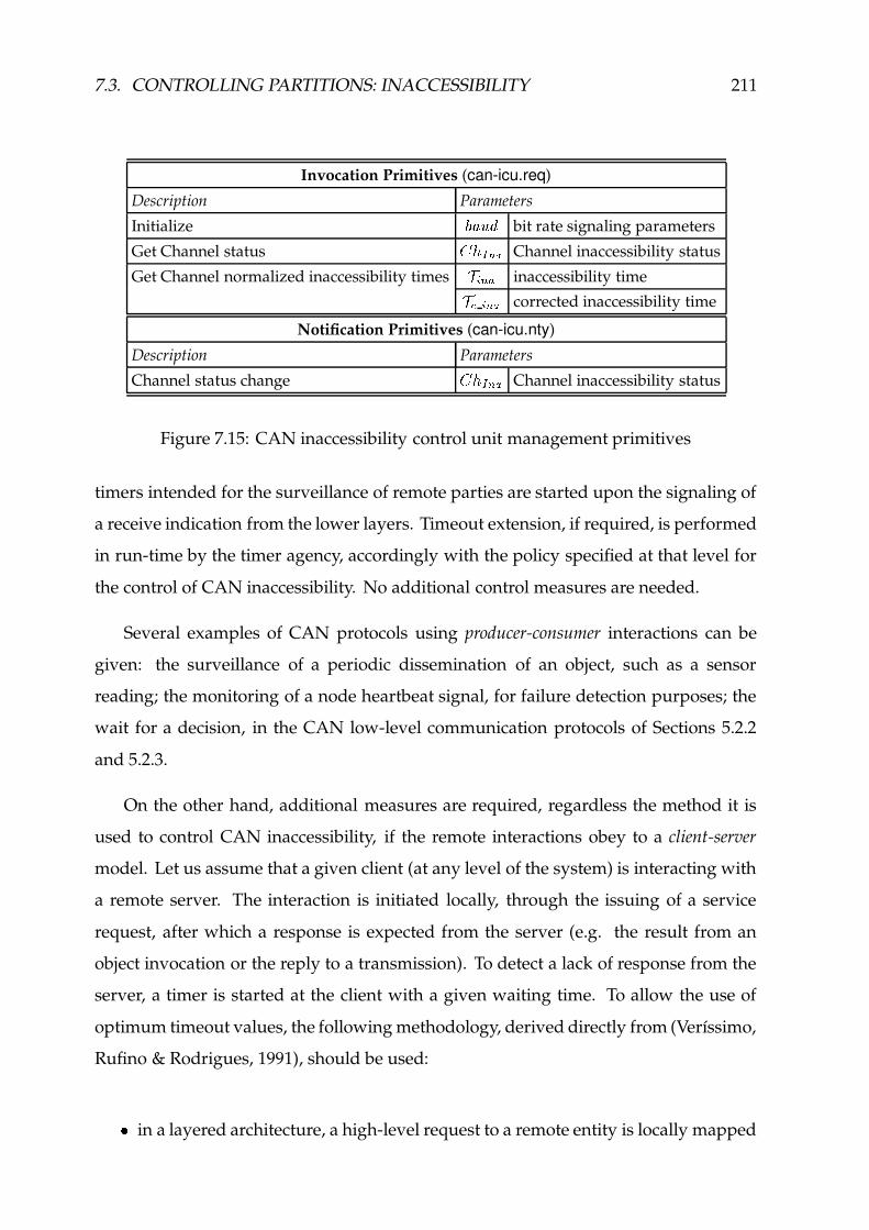
7.3. CONTROLLING PARTITIONS: INACCESSIBILITY 211
Invocation Primitives (can-icu.req)
Description Parameters
Initialize Ã8ÄyÅ�Æ bit rate signaling parameters
Get Channel status ÍÏÎ ¥ , � Channel inaccessibility status
Get Channel normalized inaccessibility times Ó � , � inaccessibility timeÓ í � , � corrected inaccessibility time
Notification Primitives (can-icu.nty)
Description Parameters
Channel status change ÍÏÎ ¥ , � Channel inaccessibility status
Figure 7.15: CAN inaccessibility control unit management primitives
timers intended for the surveillance of remote parties are started upon the signaling of
a receive indication from the lower layers. Timeout extension, if required, is performed
in run-time by the timer agency, accordingly with the policy specified at that level for
the control of CAN inaccessibility. No additional control measures are needed.
Several examples of CAN protocols using producer-consumer interactions can be
given: the surveillance of a periodic dissemination of an object, such as a sensor
reading; the monitoring of a node heartbeat signal, for failure detection purposes; the
wait for a decision, in the CAN low-level communication protocols of Sections 5.2.2
and 5.2.3.
On the other hand, additional measures are required, regardless the method it is
used to control CAN inaccessibility, if the remote interactions obey to a client-server
model. Let us assume that a given client (at any level of the system) is interacting with
a remote server. The interaction is initiated locally, through the issuing of a service
request, after which a response is expected from the server (e.g. the result from an
object invocation or the reply to a transmission). To detect a lack of response from the
server, a timer is started at the client with a given waiting time. To allow the use of
optimum timeout values, the following methodology, derived directly from (Verıssimo,
Rufino & Rodrigues, 1991), should be used:
� in a layered architecture, a high-level request to a remote entity is locally mapped

212 CHAPTER 7. SECURING REAL-TIME PROPERTIES
into a CAN layer request primitive;
� in the interface with the CAN layer, all requests are positively confirmed when the
frame is transmitted;
� in a layered architecture, the higher-level request is also confirmed: the low-level
confirmation that the request was served propagates up the layers;
� timers to control remote interactions are only started after the confirmation that
the request was issued.
This ensures that the process of waiting for a response from a remote peer entity is
initiated only after success in issuing the corresponding request. The delays associated
with the local issuing of the service request do not need to be accounted for and timers
used in the surveillance of remote interactions may then assume optimum timeout
values.
7.4 Summary
This chapter is entirely dedicated to the analysis of CAN real-time properties.
Following a structured approach to the problem of enforcing a real-time operation in
a CAN-based communication system we treat in isolation the implications that each
kind of faults (timing, omission, partitions) may have on the system behavior.
The analysis of CAN operation in the presence of partitions is the central issue of
this chapter. In particular, we discuss in detail a subtle form of partitioning, virtual
rather than physical, called inaccessibility. The study of CAN inaccessibility, presented
in this chapter, consists in the following main contributions:
� analysis of CAN inaccessibility characteristics, including the provision of a set of easy-
to-use formulas to evaluate the worst-case bounds of the periods of inaccessibility;
� definition of possible strategies to reduce the longest periods of inaccessibility;
� analysis of a set of inaccessibility control methods, relevant to CAN;
� definition and design of an effective method for the control of inaccessibility in CAN;

7.4. SUMMARY 213
� provision of guidelines on how to incorporate the control of inaccessibility at the
different levels of a CAN-based system.

214 CHAPTER 7. SECURING REAL-TIME PROPERTIES

Conclusions and FutureWork
A catedral de Burgos tem trinta metros de altura
e as pupilas dos meus olhos dois milımetros de abertura.
Olha a catedral de Burgos com trinta metros de altura!
in Antonio Gedeao, Poesias Completas.
The CAN fieldbus (BOSCH, 1991; ISO, 1993) assumes nowadays a very important
role in the design of small-scale distributed systems. Originally developed to the auto-
motive industry it has been used in more and more systems and applications, in areas
as diverse as shop-floor and process control, robotics, medical systems, locomotives
and railways, automotive, avionics and aerospace.
The CAN fieldbus is traditionally viewed as a robust real-time network, on the
ground of: using a deterministic control scheme in the access to the shared transmission
medium; exhibiting a comprehensive set of error detection and signaling procedures.
However, we have identified a set of severe dependability shortcomings in regard
to the utilization of CAN in highly fault-tolerant real-time systems and applications.
For each one of those problems, we have provided a cost-effective solution based on
the use of commercial off-the-shelf components, as described next:
� dismissing a common misconception that CAN supports a totally ordered atomic
broadcast primitive, we explained how the occurrence of network errors may lead
to: inconsistent message delivery; generation of message duplicates. Handling
the problem effectively, we presented a suite of low-level protocols that secures
both reliable and atomic multicast services (Rufino et al., 1998b).
215

216 CHAPTER 8. CONCLUSIONS AND FUTURE WORK
� given the lack of a site membership service and of a global notion of time embed-
ded in the CAN infrastructure, we have designed a suite of low-level protocols
providing: node failure detection and site membership (Rufino, 2000); fault-
tolerant clock synchronization (Rodrigues, Guimaraes & Rufino, 1998).
� since the standard CAN fieldbus is not resilient to the partitioning of the network
infrastructure, we have handled the problem through: the design of a simple and
innovative method for bus media redundancy (Rufino et al., 1999b); the use of
plain network redundancy; a combination of both redundancy schemes (Rufino,
1997b).
� finally, we have addressed the foundations of a problem which has been neglected
in many analysis of CAN timing properties. Given that CAN operation can be
disturbed by a subtle form of partitioning, virtual rather than physical (periods
of inaccessibility), we have analyzed the problem thoroughly, showing that: the
CAN protocol is able to recover from those incidents; the corresponding glitches
are time-bounded (Verıssimo, Rufino & Ming, 1997); the effects of the periods of
inaccessibility can be accommodated in the operation of the system (Rufino et al.,
2000).
This comprehensive set of simple machinery resources and low-level protocols,
was dubbed CAN Enhanced Layer (CANELy). Each component in the CAN Enhanced
Layer architecture contributes to complement/enhance the native CAN protocol, in
order to secure the strict reliability, availability and timeliness guarantees needed by
highly fault-tolerant real-time systems and applications. The result is a CAN-based
infrastructure able of extremely reliable communication.
8.1 CAN Enhanced Layer: Engineering Structure
From an engineering viewpoint, the CAN Enhanced Layer exhibits a modular
architecture which includes both hardware and software components, as shown in
Figure 8.1, and summarized next:
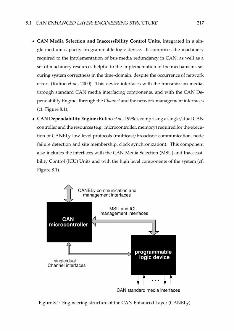
8.1. CAN ENHANCED LAYER: ENGINEERING STRUCTURE 217
� CAN Media Selection and Inaccessibility Control Units, integrated in a sin-
gle medium capacity programmable logic device. It comprises the machinery
required to the implementation of bus media redundancy in CAN, as well as a
set of machinery resources helpful to the implementation of the mechanisms se-
curing system correctness in the time-domain, despite the occurrence of network
errors (Rufino et al., 2000). This device interfaces with the transmission media,
through standard CAN media interfacing components, and with the CAN De-
pendability Engine, through the Channel and the network management interfaces
(cf. Figure 8.1);
� CAN Dependability Engine (Rufino et al., 1998c), comprising a single/dual CAN
controller and the resources (e.g. microcontroller, memory) required for the execu-
tion of CANELy low-level protocols (multicast/broadcast communication, node
failure detection and site membership, clock synchronization). This component
also includes the interfaces with the CAN Media Selection (MSU) and Inaccessi-
bility Control (ICU) Units and with the high level components of the system (cf.
Figure 8.1).
programmable logic device
MSU and ICUmanagement interfaces
single/dualChannel interfaces
CAN standard media interfaces
CANELy communication and management interfaces
CAN microcontroller
Figure 8.1: Engineering structure of the CAN Enhanced Layer (CANELy)

218 CHAPTER 8. CONCLUSIONS AND FUTURE WORK
A set of companion works have addressed the engineering of different aspects of the
CANELy architecture: CAN Dependability Engine hardware infrastructure (Monteiro
& Pedrosa, 1998); CAN atomic multicast protocols (Feio & Lageira, 1998); CAN me-
dia redundancy mechanisms (Matias, 2000); CAN fault-tolerant clock synchronization
(Guimaraes, 1996).
8.2 A Comparison with CAN and TTP
Given that the attributes of the CAN standard layer have been compared in the lit-
erature (Kopetz, 1998), and also in Section 2.5, with the attributes of the Time-Triggered
Protocol (TTP), it is mandatory to extend such analysis in order to include the CAN
Enhanced Layer (CANELy). The results from this comparison are summarized in
Figure 8.2.
The first difference signaled in Figure 8.2 between the CAN standard layer and the
CANELy architecture concerns the definition of fault confinement rules: a CANELy
node will be shutdown, by forcing it to enter what is called the bus off state, after
the node has given a pre-specified number of omission errors, prior reaching the error
passive state (Rufino et al., 1998b).
This enforces a node weak-fail-silent behavior: a node either behaves correctly or
stops if it does more than a given number of omissions. This way, the erratic behavior
of CAN error passive nodes, which represents a source of inconsistency, is controlled
(Rufino et al., 1998b).
On the other hand, the fault confinement rules used in the CANELy architecture
are in the origin of a small decrease observed in the worst-case duration of the inacces-
sibility periods (cf. Figure 8.2). The inaccessibility characteristics of TTP only recently
have began to be evaluated (Lourenco, 2002). Explicit mechanisms for the control of
inaccessibility are present only in the CANELy architecture.
The CANELy architecture exhibits the most flexible options in regard to the pro-
vision of resilience against partitions of the network infrastructure. Both media and
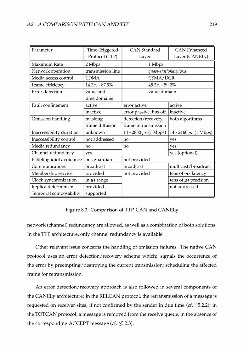
8.2. A COMPARISON WITH CAN AND TTP 219
Parameter Time-Triggered CAN Standard CAN EnhancedProtocol (TTP) Layer Layer (CANELy)
Maximum Rate 2 Mbps 1 MbpsNetwork operation transmission line quasi-stationary busMedia access control TDMA CSMA/DCRFrame efficiency 14.3% - 87.9% 45.3% - 59.2%Error detection value and value domain
time domainsFault confinement active error active active
inactive error passive, bus off inactiveOmission handling masking detection/recovery both algorithms
frame diffusion frame retransmissionInaccessibility duration unknown 14 - 2880 576 (1 Mbps) 14 - 2160 5�6 (1 Mbps)Inaccessibility control not addressed no yesMedia redundancy no no yesChannel redundancy yes yes (optional)Babbling idiot avoidance bus guardian not providedCommunications broadcast broadcast multicast/broadcastMembership service provided not provided tens of ɬ6 latencyClock synchronization in 576 range tens of 576 precisionReplica determinism provided not addressedTemporal composability supported
Figure 8.2: Comparison of TTP, CAN and CANELy
network (channel) redundancy are allowed, as well as a combination of both solutions.
In the TTP architecture, only channel redundancy is available.
Other relevant issue concerns the handling of omission failures. The native CAN
protocol uses an error detection/recovery scheme which: signals the occurrence of
the error by preempting/destroying the current transmission; scheduling the affected
frame for retransmission.
An error detection/recovery approach is also followed in several components of
the CANELy architecture: in the RELCAN protocol, the retransmission of a message is
requested on receiver sites, if not confirmed by the sender in due time (cf. ÷ 5.2.2); in
the TOTCAN protocol, a message is removed from the receive queue, in the absence of
the corresponding ACCEPT message (cf. ÷ 5.2.3).
220 CHAPTER 8. CONCLUSIONS AND FUTURE WORK
On the other hand, an error masking/diffusion algorithm is used in the EDCAN
protocol (cf. ÷ 5.2.1), to ensure message delivery to all correct nodes, even in the presence
of sender failure.
A combination of error detection/recovery and masking algorithms is used for
handling message omissions in the protocol suite supporting node failure detection,
site membership and clock synchronization functions.
The availability of reliable communication services is of fundamental importance,
e.g. to the provision of replica determinism, an issue not addressed in this dissertation.
On the other hand, though no provisions are made to avoid babbling idiot failures,
some research has been done on this issue (Tindell & Hansson, 1995; Broster & Burns,
2001a). The incorporation of babbling idiot avoidance mechanisms in the CANELy
architecture is feasible�
and would be very interesting.
Finally, temporal composability is an attribute of time-triggered architectures
(Kopetz, 1998). As a matter of fact, this issue (together with, e.g. replica deter-
minism) is a system level concern. System level attributes are not directly provided
by any network infrastructure, CAN included. Therefore, the comparative analysis of
TTP system level attributes with their absence in the CAN fieldbus infrastructure, as
performed in (Kopetz, 1998), is naturally unfair to CAN.
The work presented in this dissertation does provide the fundamental basis for the
integration of system level attributes, such as replica determinism, on top of CAN, thus
offering a highly fault-tolerant real-time distributed system.
8.3 Future Research Directions
The availability within the CANELy architecture of a programmable logic device,
needed for the implementation of the CAN media selection and inaccessibility con-
trol units, opens room for the design and integration of other relevant dependability
enforcement mechanisms.
�Being integrated as an additional unit, in the programmable logic device of Figure 8.1 - page 217.

8.4. SUMMARY OF RESULTS 221
Future research may address the design of: effective mechanisms providing the
early shutdown of a node upon its permanent failure, which may significantly reduce
the worst-case inaccessibility bound, Ü � , � ; Medium quarantine techniques, aiming to
guarantee, with a very high probability, an extremely low Channel omission degree at
the MAC-level ( �æ i*Р� �); hardware assistance to the total ordering of messages, in
dual-redundant Channel architectures.
A slightly different line of research is inspired by the recent public domain avail-
ability of CAN controller VHDL cores (Stagnaro, 2000). In this context, the integration
of CAN dependability enforcement mechanisms directly into the CAN controller ar-
chitecture is a cost-effective solution. As a matter of fact, some mechanisms may even
be optimized.
One other interesting project concerns the application of our CAN-based depend-
able communications infrastructure to the design and development of a distributed
agency for reliable input/output, where the nodes integrating the interfaces with the ex-
tremities of the system (i.e. sensor/actuator connections) would exhibit a simplified
architecture. However, a set of fundamental issues have to be addressed. For example:
how much of the CANELy functionality would be effectively needed in these simplified
nodes to ensure the required dependability levels? what strategies should be followed
in case of sensor/actuator failure?
8.4 Summary of Results
Having originally identified that CAN, the Controller Area Network, exhibits a
set of dependability shortcomings that would lead to the implementation of fault-
tolerant systems that would function incorrectly, with unpredictable consequences for
the controlled systems, we have handled the problem effectively, through the definition
and design of a CAN-based infrastructure able of extremely reliable communication.
A combination of machinery resources and low-level software components, which
we have dubbed CAN Enhanced Layer (CANELy), adds to the CAN standard layer the
following functionalities:

222 CHAPTER 8. CONCLUSIONS AND FUTURE WORK
� resilience to network partitioning, through redundancy;
� provision of semantically rich communication services, which includes re-
liable group communication, node failure detection, site membership and
clock synchronization;
� hard real-time operation, in the presence of network errors (i.e. periods of
network inaccessibility).
The original contributions to the problem of building a CAN-based distributed
fault-tolerant real-time embedded system, addressed in this dissertation, are summa-
rized next:
� clear and accurate identification of CAN weaknesses with respect to the
reliability of communications;
� formalization of CAN physical and data link layer properties in a system
model;
� detailed specification of an innovative and extremely simple method for the
implementation of bus media redundancy in CAN;
� definition and design of a suite of reliable communication services, which
includes:
– fault-tolerant broadcast and group (multicast) communications;
– node failure detection and site membership;
– clock synchronization.
� detailed analysis of CAN behavior in the presence of faults, showing that
the corresponding glitches in network operation are time-bounded, and
deriving the value of those bounds;
� definition of a methodology to enforce system correctness in the time-
domain, despite the occurrence of network errors.

8.5. FINAL REMARKS 223
8.5 Final Remarks
Other researchers have cited some of our technical documents, that are in the basis
of this dissertation. For example: in (Ventura, 2001), the RELCAN protocol is studied
with respect to: decomposition in a set of fundamental modules (micro-protocols);
analysis of micro-protocol schedulability and response time characteristics.
In (Pinho, 2001), the author claims that in the EDCAN protocol "the worst-case
response time grows exponentially with the number of nodes", although that is not
the case. Then, the author presents an alternative suite of atomic broadcast protocols,
inspired by the ~ -protocols (Cristian et al., 1985), based on the conservative assumption
that the inconsistent omission degree boundú � �
. This leads to performance figures
that are only comparable with a similar omission degree, and is obviously only valid
forú � �
.
However, the value of the inconsistent omission degree bound (ú) that should be
assumed for the system depends on the network error characteristics at each particular
CAN setting. These may strongly depend on external and environment conditions that
are usually unknown during the system design phase. In any case, a violation of the
assumed inconsistent omission degree bound would have a very high cost, given that it
would have unpredictable consequences on the communication and on the controlled
systems.
This clearly justifies our approach of allowing an arbitrary value for the inconsistent
omission degree bound in the design of highly fault-tolerant CAN-based real-time
systems.
Our work on the analysis of fault-tolerant broadcast in CAN is cited, for example in
(Kaiser & Mock, 1999; Kaiser & Livani, 1999; Tran, 1999). The analysis of CAN behavior
in the presence of inaccessibility is referenced in (Kaiser & Livani, 1998; Livani et al.,
1998; Broster & Burns, 2001b) and used in (Pinho et al., 2000). Finally, the use of the CAN
fault-tolerant clock synchronization algorithm described in (Rodrigues, Guimaraes &
Rufino, 1998) is assumed in (Broster & Burns, 2001b) and (Pinho, 2001).

224 CHAPTER 8. CONCLUSIONS AND FUTURE WORK
Abbreviations andAcronyms
ACK Acknowledgment
AMD Advanced Micro Devices, Inc.
CAL CAN Application Layer
CAN Controller Area Network
CANELy CAN Enhanced Layer
CORBA Common Object Request Broker Architecture
CRC Cyclic Redundancy Check
CSMA Carrier Sense Multiple Access
CSMA/CD Carrier Sense Multiple Access with Collision Detection
CSMA/DCR Carrier Sense Multiple Access with Deterministic Collision Resolution
CiA CAN in Automation
DCX-51 Distributed Control eXecutive
DLC in CAN, Data Length Code
DM Deadline-Monotonic scheduling
Del Delimiter
225

226 APPENDIX A. ABBREVIATIONS AND ACRONYMS
Delta-4 Definition and Design of an open Dependable Distributed system architecture
(ESPRIT Project 2252)
EDCAN in CANELy, Eager Diffusion CAN protocol
EDF Earliest Deadline First scheduling
EFS in CAN, End-of-Frame Sequence
EIA Electronic Industries Association
EOF End-Of-Frame
EOT in CAN, End-Of-Transmission sequence
ERCOS Embedded Real-time Control Operating System
F-CAN in CANELy, the message Fragmentation protocol
FDA in CANELy, the Failure Detection Agreement protocol
FDDI Fiber distributed Data Interface
FPGA Field Programmable Gate Array
G-CAN in CANELy, the Group management protocol
GBS in BITBUS, Generic Bus Services
I/O Input/Output
ICU in CANELy, Inaccessibility Control Unit
IDE in CAN, IDentifier Extension
IEEE Institute of Electrical and Electronic Engineers
IMD in CAN analysis, Inconsistent Message Duplicates
IMO in CAN analysis, Inconsistent Message Omissions
ISO International Organization for Standardization
227
L-CAN in CANELy, a multicast variant of a Lazy reliable message diffusion protocol
LAN Local Area Network
LAS in PROFIBUS, List of Active Stations
LCAN in CAN analysis, LLC-level properties
LLC Logical Link Control
LONWORKS Local Operating NetWORKS
LSA in CANELy analysis, the Life-Sign Agreement protocol
LSB in CANELy analysis, the Life-Sign Broadcast protocol
LSE Local Support Environment
MAC Medium Access Control
MCAN in CAN analysis, MAC-level properties
MGS Multicast Group of Stations
MSU in CANELy, Media Selection Unit
NRZI Non-Return-to-Zero Inverted
NRZ Non-Return-to-Zero
OSEK Open Systems and the Corresponding Interfaces for Automotive Electronics
OSI Open System Interconnection
PCAN in CAN analysis, Physical level properties
PHY PHYsical layer
PROFIBUS PROcess FIeldBUS
R-CAN in CANELy, the multicast variant of RELCAN
RAC in BITBUS, Remote Access and Control

228 APPENDIX A. ABBREVIATIONS AND ACRONYMS
REC in CAN, Receive Error Count
RED-CAN Redundant CAN interface, a commercial product from NOB Electronik AB
RELCAN in CANELy, RELiable message diffusion CAN protocol
RHA in CANELy, the Reception History Agreement protocol
RHB in CANELy analysis, the Reception History Broadcast protocol
RHM in CANELy analysis, the Reception History Matrix
RHV in CANELy, the Reception History Vector
RLB in CANELy, the Restricted Life-sign Broadcast protocol
RTEMS Real-Time Executive for Multiprocessor Systems
RTR in CAN, Remote Transmission Request
SAE Society for Automotive Engineers
SDLC Synchronous Data Link Control
SDS Smart Distributed Systems
SOF Start-Of-Frame
SRR in CAN, Substitute Remote Request
T-CAN in CANELy, the multicast variant of TOTCAN
TDMA Time Division Multiple Access
TEC in CAN, Transmit Error Count
TOTCAN in CANELy, TOTally ordered message diffusion CAN protocol
TTP/C Time Triggered Protocol for SAE Class C Applications
TTP Time Triggered Protocol
VHDL Very High-speed integrated circuits hardware Description Language

229
WorldFIP World Factory Instrumentation Protocol
ber bit error rate
eCOS embedded Configurable Operating System
mid in CANELy, message identifier
pid in CANELy, protocol identifier
tid in CANELy, timer identifier
û C/OS MicroController Operating System

230 APPENDIX A. ABBREVIATIONS AND ACRONYMS

CAN Frame Formats andTimings
This appendix provides a description of the formats defined in the standard CAN
documents (BOSCH, 1991; ISO, 1993; ISO, 1995) for the data, remote, error signaling
and overload frames. For each one of those frames, we also derive a set of expressions
allowing the computation of their minimum and maximum normalized durations.
B.1 Data and Remote Frames
The CAN specification allows two different values (11 and 29 bits) for the length
of a data/remote frame identifier. In order to maintain the compatibility between the
two definitions, slightly distinct frame formats are used. We start by describing the
structure of the standard CAN 2.0A frame (11-bit identifier), illustrated in Figure B.1:
SOF CRCDelimiter
ACKDelimiter
ACKSlot
CRCSequence EOFBase Identifier DLC Data FieldRTR rv1 rv0
11bit1bit 1bit 1bit 1bit 4bit 0-64bit 15bit 1bit 1bit 1bit 7bit
End of Frame SequenceBit-Stuffing and CRC Coverage
Arbitration Field Control Field
CRC Field ACK Field
does not exist in remote frames
Figure B.1: CAN 2.0A data/remote frame
f SOF - Start-Of-Frame delimiter - the transfer of a data/remote frame is usually started
with the transmission of a single dominant bit. However, a CAN controller in
conformity with the CAN 2.0B specification may omit the transmission of the SOF
231

232 APPENDIX B. CAN FRAME FORMATS AND TIMINGS
delimiter when it has a frame queued for transmission and detects a dominant value
at the third bit of the intermission�. In this case, the CAN controller initiates frame
transmission with the issuing of the first bit of the base identifier.
f base identifier - a 11-bit sequence that, at a particular moment, identifies system-wide
a given CAN 2.0A frame. A restriction applies to the definition of base identifiers: at
least one of the seven most significant bits must be dominant.
f RTR - Remote Transmission Request - a single bit that assumes a dominant value for
data frames or is set recessive in remote frames. Hence, for the same base identifier
the transmission of the data frame takes precedence over remote frames.
f control - a 6-bit field, where the first two bits are always set dominant. The following
four bits represent the Data Length Code (DLC) and may assume any value in the
interval [0,8], indicating the number of bytes in the data field. In remote frames there
is no data field. Though any value, within the admissible range [0,8], may be used in
the DLC field of a given remote frame, one must ensure that all the nodes transmit
the same value. Otherwise, an un-resolvable collision would prevail.
f data field - holds the data to be transfered. The frame payload can assume any value
between zero and eight bytes.
f CRC field - a 16-bit field consisting of the following two elements:
– CRC sequence - a 15-bit cyclic redundancy code (CRC) used by receivers
to check the integrity of the incoming stream, up to the CRC delimiter.
– CRC delimiter - a single bit always set to a recessive value.
f acknowledgment field - a two-bit field used by receivers to acknowledge a correct
data/remote frame transfer, if no errors have been detected up to the end of the CRC
sequence. It contains two different elements:
– ACK slot - a single bit sent with a recessive value by the transmitter; its
value is changed to dominant by any node receiving a data/remote frame
without CRC errors.
– ACK delimiter - a single bit assuming always a recessive value.
f EOF - End-Of-Frame delimiter - a fixed form sequence of seven recessive bits.
�The bus idle period, with the nominal duration of three bit times, that usually precedes any data or
remote frame transmission.

B.1. DATA AND REMOTE FRAMES 233
The length of the CAN data/remote identifiers was extended from 11 to 29 bits in
the CAN 2.0B specification (BOSCH, 1991; ISO, 1995), as illustrated in Figure B.2. Com-
patibility with the former CAN 2.0A specification is maintained, through a different
utilization given to the two bits that immediately follow the base identifier.
SOF CRCDelimiter
ACKDelimiter
ACKSlot
CRCSequence EOFIDESRR Extended Identifier DLC Data FieldRTR rv1 rv0
End of Frame SequenceBit-Stuffing and CRC Coverage
Arbitration Field Control Field
CRC Field ACK Field
1bit 11bit 1bit 1bit 18bit 1bit 1bit 1bit 4bit 0-64bit 15bit 1bit 1bit 1bit 7bit
BaseIdentifier
only exists in CAN 2.0B{
RTR rv1
d d CAN 2.0A data frame
r d CAN 2.0A remote frame
r r CAN 2.0B frameSRR IDE
does not exist in remote frames
Figure B.2: CAN 2.0B data/remote frame
Those two bits start a sequence, which only exists in the extended CAN 2.0B format
(BOSCH, 1991; ISO, 1995), having the following specification:
f SRR - Substitute Remote Request - a single recessive bit.
f IDE - Identifier Extension - a single bit, set recessive to break the format of CAN 2.0A
frames, thus signaling the presence of the extended identifier field.
f extended identifier - a 18-bit sequence of additional identifier bits.
The two frame formats are distinguished as follows: in a CAN 2.0A frame, the RTR
bit and the control field follow the base identifier; conversely, in a CAN 2.0B frame
the base identifier is followed by a unique SRR/IDE sequence of recessive bits that
unambiguously identify the CAN 2.0B format (Figure B.2).
The SRR and IDE bits are included in the arbitration field. In the competition with
CAN 2.0A traffic for bus access, the recessive value of those bits in CAN 2.0B frames
always lead to the loss of the arbitration process.

234 APPENDIX B. CAN FRAME FORMATS AND TIMINGS
The size of the CRC sequence and the corresponding generator-polynomial are the
same for both formats. This check sequence was derived from a cyclic redundancy
code best suited for streams with bit counts less than 127 bits (BOSCH, 1991; ISO, 1995).
Most of nowadays commercially available CAN controllers (Intel, 1995; Siemens,
1995a; Philips, 1997a; Motorola, 1998; Dallas, 1999) and CAN design cores (Altera, 1997;
SICAN, 1998) support the handling of both CAN 2.0A and CAN 2.0B frame formats.
B.2 Error Frames
In CAN, the occurrence of an error is signaled, upon its detection, through the
issuing of an error frame. An error frame begins with an error flag and ends with
an error delimiter. An error flag consists of six consecutive bits of identical polarity,
assuming dominant values if transmitted from an error active node or a recessive value,
otherwise. The error delimiter is made from eight consecutive recessive bits.
The occurrence of a given error, e.g. the corruption of a bit by electromagnetic
interference (IBET, 1995; Bridal, 1989), may affect only a subset of the nodes. Hence:
� the subset of the nodes � detecting the error, start the error signaling process
by transmitting one error flag;
� the transmission of this error flag violates the bit-stuffing coding rule � , thus
allowing all nodes to detect the error;
� nodes that did not have detected any error earlier, respond by starting their
own transmissions of one error flag;
� the different error flag transmissions may totally or partially overlap; in the
worst-case, two non-overlapping error flags flow on the network (Figure B.3);
� a bus idle period, corresponding to the error delimiter field, ends the error
signaling process.
�This subset may have only one element.�Exception made to the error flags issued from passive receivers (BOSCH, 1991; ISO, 1993).

B.3. OVERLOAD FRAMES 235
6 bits 8 recessive bits0-6 bits
Error Flag Error Flag Error Delimiterdata/remote frame
transmitted by node k
transmitted by node n
bit corruptionerror flags may overlap
Error Occurrence
Error Detection
Error Signaling
Figure B.3: CAN error frame
B.3 Overload Frames
The signaling of overload conditions in the CAN bus follows a methodology similar
to the signaling of error situations. The process is started with the transmission of an
overload flag and ends with a overload delimiter. The overload flag always consists of
six consecutive dominant bits. The overload delimiter is made from eight consecutive
recessive bits. The overload flags transmitted by the different nodes may totally or
partially overlap, as illustrated in Figure B.4.
Overload Signaling
Overload Flag Overload Delimiter
transmitted by node k
transmitted by node n
8 recessive bits
intermission violation
nominal intermission"3 recessive bits"
6 dominant bits
Overload Flag
0-6 dominant bits
data/remote frame
overload flags may overlap
Figure B.4: CAN overload frame
B.4 Frame Timings
In this section we establish a set of easy-to-use expressions that allows the compu-
tation of the minimum and maximum normalized durations of each CAN frame. This
evaluation is performed independently of the actual network bit signaling rate. To
obtain the real duration of a frame, say « G u � �Èw , the normalized frame duration, ª G u � � w ,must be multiplied by the nominal bit time, « �V�-D .

236 APPENDIX B. CAN FRAME FORMATS AND TIMINGS
« G u � � w � ª G u � � w � « �V�-D (B.1)
where, « �V�-D � ��4�sE } , being� � � Ó the nominal rate of bit signaling, on the bus. The
normalized duration of a bit is represented by ª �V�-D , being ª �V�3D� �bit-time.
Data and remote frames
The main parameters that define the normalized duration of a data frame are the
frame format specification (2.0A or 2.0B) and the size of its data field. However, with
exception of the end-of-frame sequence, all the fields in a frame are subject to bit-stuffing
coding. That means: the actual duration of a frame may depend on its contents.
To establish a lower bound ( �c� ) for the duration of a data frame, we assume no bits
are stuffed in the outgoing stream � . Therefore:
ª �c�} �sDO� � J>A G � v\��A4} �sDO� ��A4w GIB L � ª �V�-D (B.2)
The meaning of the different length parameters in equation (B.2) is explained next:
Ö A Gb� v - represents the length (in bits) of fixed size fields subject to bit-stuffing.
It includes the start-of-frame delimiter, the arbitration and control fields, as
well as the CRC sequence. Its exact value depends on CAN frame format
specification (2.0A or 2.0B).Ö A } �sDO� - represents the length (in bits) of the data field. It varies between 0 and
64, in 8 bit increments.Ö A4w GIB - represents the length (in bits) of the fixed form sequence, not subject
to bit-stuffing, that ends every data or remote frame. It includes the CRC
delimiter, the acknowledgment field and the end-of-frame delimiter.
�Equations (B.2) up to (B.7) do not account for the nominal three bit bus idle period that usually
precedes any data or remote frame transmission (intermission).

B.4. FRAME TIMINGS 237
On the other hand, to establish an upper bound ( E� ) for the duration of a data frame,
we assume that all the fields subject to bit-stuffing exhibit a pattern that leads to the
maximum insertion of stuffed bits. Therefore:
ª E�} �sDO� � �A4Gb� v �éA } �'DO� � � ��� A Gb� v � A B4DFEHGIG ��A4} �sDO�
A B4DFEHGIG � � � �éA w GHB�� � ª!�V�-D (B.3)
where � represents the floor function � ; A B4DFEHGIG represents the bit-stuffing width, i.e.
the maximum number of consecutive bits of identical value that can be found in the
outgoing stream, stuffed bits included (Figure B.5).
1 1 1 1 1 0 0 0
stuffed stream
0 0 0 0 0 1 1 1 1 0 0 0 row data
0 0
SOF
0
0 0 1
recessive (logical one)
dominant (logical zero)
Bus State
Start-Of-Frame delimiter(SOF)
Node n0 0 0
stuffl
Figure B.5: Details of CAN data/remote frame bit-stuffing coding
The minimum and maximum durations of a data frame can be derived by setting
A } �sDO� to zero in equation (B.2) and by setting A } �sDO� to the maximum value (64 bits) in
equation (B.3), respectively. The minimum and maximum durations of remote frames
can be derived from equations (B.2) and (B.3), by setting A(} �sDO� to zero. The results from
such an evaluation are summarized in Table B.1.
A more detailed analysis on data/remote frame duration variability, including a
study on the probability of insertion of a given number of stuffed bits, can be found in
(Rauchaupt, 1994).
�The floor function �'ß � is defined as the greatest integer not greater than ß .

238 APPENDIX B. CAN FRAME FORMATS AND TIMINGS
Error and overload frames
Error and overload frames are not subject to bit-stuffing coding. The evaluation of
their best ( � í ) and worst-case ( h í ) durations is extremely simple. Equations (B.4) and
(B.5) specify those durations for error frames:
ª � íwCu>u'Ñ8u � J(A GH�k�Pô ��A4}'w � L � ª �V�-D (B.4)
ª h íwCu>u'Ñ8u � J(R � A4GH�k�Pô���A }'w � L � ª!�V�-D (B.5)
where A GH�õ�(ô and AC}'w � are, respectively, the length in bits of the error flag and of the error
delimiter.
Similar expressions can be established with regard to the evaluation of overload
frame durations:
ª � íÑ � Ñ � } � J>A GI�k�Pô �éA4}'w � L � ª �V�-D (B.6)
ª h íÑ � Ñ � } � J>R � A4GI�k�Pô��éA }'w � L � ª!�V�-D (B.7)
Analytic results
The numerical values for the normalized duration bounds of data/remote frames,
evaluated through the application of equations (B.2) and (B.3) to the shortest (i.e. best-
case � ) and to the longest (i.e. worst-case � ) frame sizes, respectively, are shown in
Table B.1. For completeness, Table B.1 also includes error and overload frame timings.
The set of frame related parameters, defined in conformity with the CAN standard
specification (BOSCH, 1991; ISO, 1993; ISO, 1995), do include:
�Signaled with superscript �L¹ .�Signaled with superscript FG¹ .

B.4. FRAME TIMINGS 239
Ò total length of the frame fixed-size fields, subject to bit-stuffing: g Gb� vnçìë;í bits (CAN 2.0A),
g G � v�çìå�í bits (CAN 2.0B);Ò end-of-frame sequence (not subject to bit-stuffing) length: g w GIBMç yê bits;Ò bit-stuffing coding width: g BCDFEHGHG çìå bits;Ò error/overload flag length: g GI�k�Pô çìé bits;Ò error/overload delimiter length: g4}'w � ç z bits.
Duration (bit-times)Frame Symbol CAN 2.0A CAN 2.0B
min. ( � í ) max. ( h í ) min. ( � í ) max. ( h í )Data frame ªQ} �'DV� 44 132 64 157Remote frame ªnu'} �sDO� 44 52 64 77Error frame ª7wCu(uPÑ8u 14 20 14 20Overload frame ªQÑ � Ñ � } 14 20 14 20
Table B.1: Normalized duration of CAN frames
Note that equations (B.2) up to (B.7), as well as the results of Table B.1, do not
account for the nominal duration of the intermission period, i.e. the nominal bus
idle period that usually precedes the transmission of any data or remote frame. The
normalized duration of the nominal intermission, which corresponds to the duration
of the interframe space imposed by a error active node in normal circunstances , is
represented by ª �FGHB , and given by equation:
ª �FGHBp� A �FGHB � ª �V�-D (B.8)
where, A �FGHB�� ³ bits, is the nominal length (in bits) of the intermission (BOSCH, 1991;
ISO, 1993) and therefore, ª �FGHB°� ³ bit-times.
!I.e., no bit corruption by electromagnetic interference and nodes correctly synchronized with the
bus bit stream.

240 APPENDIX B. CAN FRAME FORMATS AND TIMINGS

CAN Enhanced LayerMessage Encapsulation
This appendix defines how the control information of the CANELy protocol suite is
encapsulated within the base/extended identifier fields of a standard CAN 2.0B frame.
Two slightly different definitions of such fields concern the use of the CANELy
group communication protocol suite (cf. ÷ 5.3) and the CANELy broadcast protocols
(cf. ÷ 5.2 and ÷ 5.4). The specification of the control information used by the CANELy
group communication protocol suite is drawn in Figure C.1 and described next:
Base Identifier (11 bits) Extended Identifier (18 bits)
6 bits 6 bits 2 bits3 bits 8 bits4 bits
G-fieldsender idA-field pid sn
u-field (urgency)
high
low
{
L-bit (low-level protocol)
p-field (group/broadcast protocols)
T-CANR-CANL-CANreservedreservedF-CANreservedbroadcast protocols
EDCANG-CAN
control (EDCAN retransmissions)control (hard real-time)data (hard real-time)control (soft real-time)data (soft real-time)control (non real-time)data (non real-time)(not used)
dddddrdrddrrrddrdrrrdrrr
--------
dddddrdrddrrrddrdrrrdrrr
--------
dr
--
Figure C.1: CANELy control information for group communication
f u-field - this 3-bit field defines the urgency of CANELy messages. Several options
are possible for the assignment of urgency values as a function of message types
(control/data). In Figure C.1 it is specified one possible assignment policy: within
241

242 APPENDIX C. CAN ENHANCED LAYER MESSAGE ENCAPSULATION
each class, control frames have precedence over data messages; traffic could be
classified in three urgency classes (hard real-time, soft real-time, non real-time). The
non assignment of any class to lowest possible urgency is in conformity with the
CAN standard specification (BOSCH, 1991; ISO, 1993), which obliges to the presence
of at least one dominant bit (d) in the first seven bits of the CAN base identifier.f A-field - arbitration field - this 6-bit contains information concerning the scheduling
of message transmit requests. This field may have different meanings, depending on
the urgency class and on the message scheduling policy to be used. Some possible
options have been described in the literature (Tindell & Burns, 1994b; Zuberi & Shin,
1997; Livani et al., 1998).
This field may be reused with a different meaning, by some CANELy protocol entities.
For example, it may be reused by the EDCAN protocol (cf. ô 5.2.1), to hold the source
identifier�, during EDCAN frame retransmissions.
In addition, it may also be used to specify different control message types, to be
disseminated by the EDCAN protocol.f sender id - sender identifier - a 6-bit field that uniquely defines the identity of each
network node. In case of frame retransmission, by the EDCAN protocol (cf. ô 5.2.1),
this field holds the identity of the original sender.
f pid - protocol identifier - identifies which protocol in the CANELy protocol suite is
intended process a given frame.
– L-bit - low-level protocol identifier - identifies the low-level protocol which
will process the frame (EDCAN/G-CAN).
– p-field - group/broadcast protocol identifier - this 3-bit field identifies the pro-
tocol that will process the frame. Several group communication protocols
are specified in Figure C.1. One particular value references all the broadcast
protocols, to be specified ahead.
f sn - sequence number - a 2-bit number defining the order of frame transmissions from
a given node and protocol.f G-field - group address field - identifies the set of nodes intended to receive this message
(group address). In a node, specifies the application/process to which the frame is
addressed.
�The source identifier is a 6-bit field identifying the node that is actually retransmitting the frame.

243
The control information specifically used by the CANELy broadcast protocols is
specified in Figure C.2. In the absence of further reference, the CANELy message fields
are used as defined in the group communication protocol suite. Assuming the p-field is
set with the value referencing the broadcast protocols, the last eight bits of the extended
CAN identifier are redefined, as follows (Figure C.2):
Base Identifier (11 bits) Extended Identifier (18 bits)
6 bits 6 bits 2 bits3 bits 8 bits4 bits
sender idA-Field pid sn
u-field (urgency){
p-field (broadcast protocols)
{{ {
TOTCANRELCANFailure Dect./MembershipClock Synchronizationreservedreservedreservedreserved
B-field
Msg. Type
M-field
dddddrdrddrrrddrdrrrdrrr
--------
Figure C.2: CANELy control information for broadcast protocols
f B-field - Broadcast Protocol - this 3-bit field defines which broadcast protocol is in-
tended to process the current frame. Several options are defined for this field, in the
specification of Figure C.2.f M-field - micro-protocol/message field - this 3-bit field defines, inside each broadcast
protocol, which entity is intended to process the current frame and/or the kind of
message being transfered.
For example, with regard to the node failure detection and site membership services of
Section 5.4, the RLB, FDA, RHA or the membership protocol entities can be specified.f Message Type - This 2-bit field specifies the message type to be exchanged between
broadcast (micro) protocol entities.
For example, again with regard to the node failure detection and site membership
services of Section 5.4, the membership protocol will issue and process join/leave
messages.

244 APPENDIX C. CAN ENHANCED LAYER MESSAGE ENCAPSULATION

Bandwidth Utilization byMembership Protocols
This appendix analyzes the utilization of CAN bandwidth by each of the agreement
enforcement micro-protocols discussed in Section 5.4.1 and by the node failure detection
and site membership services, described in Sections 5.4.2 and 5.4.3.
D.1 Analysis of Agreement Micro-Protocols
The analysis of CAN bandwidth utilization by the low-level agreement enforcement
micro-protocols discussed in Section 5.4.1, is provide next. For each micro-protocol
we analyze the corresponding best and worst-case scenarios, that we signal with the
superscripts � í and h í , respectively.
RECEPTION HISTORY BROADCAST
The CAN bandwidth consumed in each round by the RHB protocol is accounted
for considering the transmission of a reception history vector (RHV) message from each
active node, in the period of reference corresponding to the protocol round.
ª � íu N8� � ) � ª � íu NUk (D.1)
where: ) , is the number of nodes; ª7u NUk , is the normalized duration of a reception history
vector message being the superscript � í used to signal its minimum duration.
245

246 APPENDIX D. BANDWIDTH UTILIZATION BY MEMBERSHIP PROTOCOLS
The maximum CAN bandwidth consumed by the RHB protocol in the same period
of reference is obtained assuming the transmission of a reception history vector message
of maximum length, that we denote by ª h íu NUk . Thus:
ª h íu N8� � ) � ª h íu NUk (D.2)
LIFE-SIGN BROADCAST
The CAN bandwidth consumed in each round by the LSB protocol is accounted
for considering the transmission of a life-sign message from each active node. Given
life-sign messages only disseminate control information, CAN remote frames are used.
Thus:
ª � í�õBb� � ) � ª � í�õB (D.3)
where, ª �kB is the normalized duration of a life-sign message and the superscript � í is
used to signal its minimum duration.
The corresponding worst-case value, signaled by the superscript h í , is simply given
by equation:
ª h í�kB¸� � ) � ª h í�õB (D.4)
RESTRICTED LIFE-SIGN BROADCAST
In the best-case, the utilization of CAN bandwidth by the RLB protocol during
a period of reference, assumes that one single node transmits a life-sign message of
minimum length, as specified by equation:
ª � íu �c� � ª � í�kB (D.5)

D.1. ANALYSIS OF AGREEMENT MICRO-PROTOCOLS 247
The corresponding worst-case value is obtained assuming that in the same period
of reference, at the most�
nodes transmit a life-sign message of maximum length. Thus:
ª h íu �c� J �L � � � ª h í�õB (D.6)
Naturally, the network bandwidth consumed in the worst-case by the RLB protocol
comes up to the maximum network utilization of the LSB protocol, if all the nodes need
to issue a life-sign (of maximum duration) in the same protocol round, i.e. if� � ) .
LIFE-SIGN AGREEMENT
The CAN bandwidth consumed by the LSA protocol, in a period of reference
corresponding to a single protocol execution, is obtained assuming a given number of
nodes ) is in the active state and it is given by:
ª � í�kB8� � ) � J(R � ª � í�kB L (D.7)
ª h í�kB8� � ) � J(³ � ª h í�kB L(D.8)
The best-case value (equation D.7) accounts for the transmission of a life-sign mes-
sage from each active node, assuming the perfect “clustering” of all life-sign retransmis-
sions (cf. Figure 5.3, in page 96). Conversely, equation (D.8) accounts for the worst-case
value and assumes that none of the life-sign retransmissions will “cluster” perfectly.
FAILURE DETECTION AGREEMENT
In the analysis of the network bandwidth consumed by the FDA protocol, it is
assumed that in the best-case a single node fails, during a period of reference. In
addition, we consider that all the active nodes consistently detect the node failure and

248 APPENDIX D. BANDWIDTH UTILIZATION BY MEMBERSHIP PROTOCOLS
start the transmission of the failure-sign message simultaneously (perfect “clustering”).
That means:
ª � íG } � � ª � íGHB (D.9)
where, ª � íGHB is the minimum normalized duration of a failure-sign message.
Conversely, in the accounting of the corresponding worst-case value we consider
that the failure is inconsistently detected by the active nodes. The retransmission of a
failure-sign message by the nodes that have not detect the failure follows the original
failure-sign dissemination, but not all the retransmissions are initiated at the same time
(sub-optimum “clustering”- Figure 5.3, page 96). Therefore:
ª h íG } � J Õ L � Õ � J>³ � ª h íGIB L (D.10)
where, ª h íGIB is the maximum normalized duration of a failure-sign message and Õ is the
maximum number of node crash failures, in the period of reference.
RECEPTION HISTORY AGREEMENT
The utilization of CAN bandwidth by the RHA protocol is analyzed next. For
a best-case scenario, we assume: all the correct nodes hold consistent �(0),+ values,
meaning no more than� � ú transmissions of a RHV signal are required; all pending
transmit requests are aborted with success. Thus:
ª � íu Nb� � J � � ú L � ª � íu NUk (D.11)
where, ª � íu NUk is the minimum normalized duration of a RHV signal andú, the inconsistent
omission degree bound (LCAN6, in Figure 4.7 - page 84).
The occurrence ofú
inconsistent omission failures, during a period of reference, is
assumed to account for the maximum CAN utilization by the RHA protocol. In the

D.1. ANALYSIS OF AGREEMENT MICRO-PROTOCOLS 249
worst-case: the protocol is executed inú � � rounds, beginning with the dissemination
of a �o(*),+ value that includes all the (inconsistent) join requests; in each round, no more
than one inconsistent join indication is removed from the current �-(*),+ value.
A process to abort the execution of a given protocol round is initiated: whenever
a new �o(*),+ is established and the execution of a new round is started; after the
reception of� � ú copies of the corresponding RHV signal. Given the effects of protocol
processing delays, the transmission of the RHV signals associated to a given round
may be interleaved with the transmission of pending RHV signals from the previous
round, as illustrated in Figure D.1: it may take up to a period equivalent to the duration
of A RHV signal transmissions for a node to initiate the next round; it may take up to
a second period of the same duration, to have all the active nodes executing the same
protocol round�.
Node n
Node k
Node 1
inconsistent join request
Node 2
k n21 k n21
RHV k n21
RHV RHV
node n does notreceive the join request
h RHV signalsj RHV signals
RHV signal
min{j+h,h}=hRHV signals
RHV signal
g=min{j-1,h} RHV signals
Active nodeInactive nodej=1 h=1round 2 periods
round 1 periods
Figure D.1: Operation of the RHA protocol in an inconsistent state
As a consequence, the maximum utilization of CAN bandwidth by the RHA proto-
col, expressed by equation (D.12), results from the sum of two different contributions.
The first term quantifies the network bandwidth consumed in the execution of the firstúprotocol rounds. The second term accounts for the network bandwidth needed to
reliable disseminate the final �%(*),+ value.
ª h íu Nb� � � ú � J � �»A¬� � Û() � ú ��� � A � L � J � � ú �»A L � � ª h íu NUk (D.12)
�The maximum number of RHV signals (maximum length) that may be transmitted in those periods,
is (Rufino, 2000): u��VÆ����Zd{½�;(½��n[�½ , in the first period; � [ u��VÆ���� ù oI;>½�� , in the second period. The lastresult assumes all correct nodes receive at least obd�� RHV signal copies before the end of the first period;the process to abort further RHV transmit requests is initiated and no more than ��[�� ù o transmissionswill be performed in the second period. Otherwise, up to ½ transmissions may be issued.

250 APPENDIX D. BANDWIDTH UTILIZATION BY MEMBERSHIP PROTOCOLS
where, ª h íu NUk is the maximum normalized duration of the RHV signal,ú
is the inconsistent
omission degree bound and A represents the maximum number of message transmit
requests that cannot be timely aborted, due to protocol processing delays. The� Û() �G�
function gives the smallest number in a set of values.
D.2 Analysis of Failure Detection and Membership
The CAN bandwidth used by the node failure detection and site membership
protocols is obtained, in a best-case scenario, by considering only the effects of the RLB
micro-protocol. Thus:
ª � íG } � � B%N � ª � íu �J� (D.13)
where, ª � íu �J� is the minimum CAN bandwidth consumed by the RLB micro-protocol.
To account for the CAN bandwidth used in the worst-case by the node failure
detection and by the site membership protocol suite, one needs to consider not only
the maximum utilization of CAN bandwidth by the RLB micro-protocol but also that
during a membership cycle period: Õ nodes may fail; n nodes may issue requests to
join/leave the membership service, thus leading to the execution of the RHA micro-
protocol. Therefore:
ª h íG } � � B8N � ª h íu �c� J ��L � ª h íG } � J Õ L �»n � ª h í�õB ��ª h íu Nb� (D.14)
where: ª h í�õB , is the maximum normalized duration of a join/leave request message;
ª h íu �c� , ª h íG } � and ª h íu Nb� represent the maximum CAN bandwidth consumed, respectively,
by the RLB, FDA and RHA micro-protocols.

References
ABDELZAHER, T., SHAIKH, A., JAHANIAN, F., & SHIN, K. 1996. RTCAST: Lightweight
Multicast for Real-Time Process Groups. In: Proceedings of Real-Time Technology and
Applications Symposium. Boston, MA: IEEE.
AGILENT. 1999 (Nov.). HCPL7720 40ns Propagation Delay CMOS Optocoupler. Agilent
Technologies.
ALCATEL. 1995 (Dec.). MTC-3054 CAN Interface Data Sheet. Alcatel.
ALMEIDA, L., FONSECA, J., & FONSECA, P. 1999. A Flexible Time-Triggered Communica-
tion System Based on the Controller Area Network: Experimental Results. Pages
342–350 of: DIETRICH, D., NEUMANN, P., & SCHWEINZER, H. (eds), Fieldbus Technol-
ogy - System Integration, Networking and Engineering. Springer. (Proceedings of the
Fieldbus Conference FeT’99, Magdeburg, Germany).
ALTERA. 1997 (Sept.). CAN Bus Megafunction. Altera Corporation. Solution Brief 22.
AMD. 1989 (Feb.). The SUPERNET Family for FDDI Data Book. Advanced Micro Devices,
Sunnyvale, CA-USA.
ANSI/IEEE. 1993. 1003.1b-1993 Portable Operating System Interface (POSIX) - Part 1: API
C Language - Real-Time Extensions. IEEE Standard. ISBN 1-55937-375-X.
APPEL, W., & DORNER, J. 1995. Integration of external functions in CAN-based in-vehicle
networks. Pages 5.2–5.9 of: Proceedings of the 2nd International CAN Conference.
London, England: CiA.
251

252 REFERENCES
ASHENDEN, P. 1990 (July). The VHDL Cookbook. Department Computer Science,
University of Adelaide, South Australia. Available from the following URL:
ftp://chook.cs.adelaide.edu.au/pub/VHDL-Cookbook.
AUDSLEY, N., & BURNS, A. 1990 (Jan.). Real-Time System Scheduling. Tech. rept. YCS 134.
University of York, United Kingdom.
AZEVEDO, J. 1996 (Nov.). The WorldFIP protocol. WorldFIP International Technical Center,
Antony, France. http://www.worldfip.org.
AZEVEDO, J., & CRAVOISY, N. 1998 (Oct.). The WorldFIP protocol. WorldFIP International
Technical Center, Antony, France. Available from URL http://www.worldfip.org.
AZEVEDO, J., P., GEORS, & CRAVOISY, N. 1998 (Aug.). WorldFIP technology. World-
FIP International Technical Center, Clamart, France. Available from URL
http://www.worldfip.org.
BABAOGLU, O., & DRUMMOND, R. 1985. Streets of Byzantium: Network Architectures
for Fast Reliable Broadcasts. IEEE Transactions on Software Engineering, SE-11(6).
BAUER, G., & PAULITSCH, M. 2000. An Investigation of Membership and Clique Avoid-
ance in TTP/C. In: Proceedings of the 19th Symposium on Reliable Distributed Systems.
Nurnberg, Germany: IEEE.
BIRMAN, K., & RENESSE, R. 1994. Reliable Distributed Computing With the ISIS Toolkit.
IEEE Computer Society Press. ISBN 0-8186-5342-6.
BOSCH. 1991 (Sept.). CAN Specification Version 2.0. Robert Bosch GmbH.
BOTERENBROOD, H. 2000 (Mar.). CANopen high-level protocol for CAN-bus. NIKHEF,
Amsterdam. Version 3.0.
BOURDON, G., RUAUX, P., & DELAPLACE, S. 1996. CAN for Autonomous Mobile Robot.
In: Proceedings of the 3rd International CAN Conference. Paris, France: CiA.
BRIDAL, O. 1989 (June). Electromagnetic Compatibility Considerations for Automotive
Electronic Systems. In: Proceedings of the International Symposium on Automotive
Technology and Automation.

REFERENCES 253
BROSTER, I., & BURNS, A. 2001a. The Babbling Idiot in Event-triggered Real-time Sys-
tems. Pages 25–28 of: FOHLER, G. (ed), Proceedings of the Work-In-Progress Session,
22nd Real-Time Systems Symposium, YCS 337. London, United Kingdom: Depart-
ment of Computer Science, University of York, for IEEE.
BROSTER, I., & BURNS, A. 2001b. Timely use of the CAN Protocol in Critical Hard
Real-time Systems with Faults. In: Proceedings of the 13th Euromicro Conference on
Real-time Systems. Delft, The Netherlands: IEEE.
CALLEN, J. 1998. Distributed Control for Unmanned Vehicles. IEEE Concurrency, 6(2),
16–20.
CASALI, M., SAFADI, B., MONDADA, M., OSKARSSON, O., & GOLLER, V. 1999 (Jan.). BITBUS
Application Programmers Interface. BITBUS European Users Group.
CHANG, J., & MAXEMCHUCK, N. 1984. Reliable Broadcast Protocols. ACM Transactions
on Computer Systems, 2(3), 251–273.
CHARZINSKI, J. 1994. Performance of the Error Detection Mechanisms in CAN. Pages
1.20–1.29 of: Proceedings of the 1st International CAN Conference. Mainz, Germany:
CiA.
CHEN, B., KAMAT, S., & ZHAO, W. 1997. Fault-Tolerant, Real-Time Communication in
FDDI-Based Networks. IEEE Computer, 30(4), 83–90.
CIA. 1992 (Oct.). CAN Physical Layer for Industrial Applications - CiA/DS102-1. CiA -
CAN in Automation.
CIA. 1994 (Apr.). CAN Physical Layer for Industrial Applications - CiA Draft Standard 102
Version 2.0. CiA - CAN in Automation.
CIA. 1999 (Oct.). CANopen Cabling and Connector Pin Assignment - CiA Draft Recommen-
dation DR-303-1. Version 1.0 edn. CiA - CAN in Automation.
CRISTIAN, F. 1988. Agreeing on who is present and who is absent in a synchronous dis-
tributed system. Pages 206–211 of: Digest of Papers, The 18th International Symposium
on Fault-Tolerant Computing. Tokyo - Japan: IEEE.

254 REFERENCES
CRISTIAN, F. 1990 (Apr.). Synchronous Atomic Broadcast for Redundant Broadcast Channels.
Tech. rept. RJ 7203. IBM Research Division, San Jose, California.
CRISTIAN, F., H., AGHILI., STRONG, R., & DOLEV, D. 1985. Atomic Broadcast: From
Simple Message Diffusion to Byzantine Agreement. In: Digest of Papers, The 15th
International Symposium on Fault-Tolerant Computing. Ann Arbor, USA: IEEE.
CRISTIAN, F., DANCEY, R., & DEHN, J. 1990. High Availability in the Advanced Automa-
tion System. Pages 6–19 of: Digest of Papers, The 20th International Symposium on
Fault-Tolerant Computing. Newcastle, United Kingdom: IEEE.
CURIEL, A. 1996 (Feb.). UoSAT-12 Minisatellite Mission, Telemetry and Telecom-
mand. Surrey Satellite Technology Limited. Document available from URL:
http://teleri.ee.surrey.ac.uk/EE/CSER/UOSAT/missions/uo12/uo12 ttc.html.
CWA. 2001 (Apr.). CAN-based warehouse automation system. CiA - CAN Newsletter.
DALLAS. 1999 (Sept.). DS80C390 Dual-CAN High-Speed Microprocessor. Preliminary edn.
Dallas Semiconductors.
DCX51. 1987. DCX-51 Distributed Control Executive User’s Guide. Intel Corporation.
DEVINE, S. 1999 (Dec.). Glass Cockpit Design document - Architecture. Document Available
from URL: http://www.tzogon.com/ steve/glass cockpit/architecture.shtml.
DIGITAL. 1996. Digital Unix - Guide to Realtime Programming. Digital Equipment Corpo-
ration. Chap. Clocks and Timers.
DYKEMAN, D., & BUX, W. 1987. An Investigation of the FDDI Media-Access Control Pro-
tocol. Pages 229–236 of: Proceedings of the EFOC/LAN Conference. Basel, Switzerland:
IGI.
ECOS. 2000 (Mar.). eCos Reference Manual. Red Hat Inc.
EIA. 1978 (Dec.). RS-485 EIA Standard: Electrical Characteriscs of Balanced Voltage Digital
Interface Circuits. EIA.
ETSCHBERGER, K. 1997. CAN-based Higher Layer Protocols and Profiles. Pages xx–xx
of: Proceedings of the 4th International CAN Conference. Berlin, Germany: CiA.

REFERENCES 255
FDDI. 1987. FDDI Token-Ring Media Access Control (MAC). ANSI X3.139.
FDDI, X3T9.5. 1986. FDDI documents: Media Access Layer, Physical and Medium Dependent
Layer, Station Mgt.
FEIO, J., & LAGEIRA, J. 1998 (Feb.). CANAMp - Controller Area Network Atomic Multicast
Protocol. IST Graduation Project Report, Advisors: J. Rufino and L. Rodrigues,
Instituto Superior Tecnico, Lisboa, Portugal. (in portuguese).
FLINT, S., & KENT, L. 1981. Electronic Engine Control: Automakers Conted with One of
the Harshest Application Environments. IEEE Spectrum, 18(10), 61–62.
FONSECA, H., RODRIGUES, L., RUFINO, J., & VERISSIMO, P. 1990 (Aug.). Local Support
Environment: User Specification. Tech. rept. RT/50-90. INESC, Lisboa, Portugal.
FREDRIKSSON, L. 1995. CAN Kingdom - Revision 3.01. KVASER, Sweden.
GALLAGHER, M. 1985. Low cost Networking for Islands of Automation. Control Engin-
nering Magazine, Oct.
GERGELEIT, M., & STREICH, H. 1994 (Sept.). Implementing a Distributed High-Resolution
Real-Time Clock using the CAN-Bus. Pages 9.02–9.07 of: Proceedings of the 1st
International CAN Conference. CiA, Mainz, Germany.
GIL, J., PONT, A., BENET, G., BLANES, J., & MARTINEZ, M. 1997. A CAN Architecture
for an Intelligent Mobile Robot. In: Proceedings of the IFAC International Symposium
on Intelligent in Components and Instrumentation for Control Applications. Annecy,
France: IFAC.
GOLLER, V. 2000 (Apr.). BITBUS Extended Broadcast. BITBUS European Users Group.
GORUR, R., & WEAVER, A. 1988. Setting Target Rotation Times in an IEEE Token Bus
Network. IEEE Transactions on Industrial Electronics, 35(3), 366–371.
GUERIN, C., RAISON, H., & MARTIN, P. 1985 (Jan.). Procede de Diffusion Sure de messages
dans un anneau et dispositif permettant la mise en oeuvre du procede. French Patent -
85.002.02.

256 REFERENCES
GUIMARAES, M. 1996 (Dec.). Clock Synchronization in CAN. IST Graduation Project
Report, Advisors: J. Rufino and L. Rodrigues, Instituto Superior Tecnico, Lisboa,
Portugal. (in portuguese).
HADZILACOS, V., & TOUEG, S. 1993. Fault-Tolerant Broadcasts and Related Problems.
Chap. 5, pages 97–145 of: MULLENDER, S.J. (ed), Distributed Systems, 2nd edn. ACM-
Press. Addison-Wesley.
HARTWICH, F., & BASSEMIR, A. 1999. The Configuration of the CAN Bit Timing. Pages
xx–xx of: Proceedings of the 6th International CAN Conference. Turin, Italy: CiA.
HEINS, E. 1994. A Real-Time PC with iRMX for Windows controls Medical System
Components directly via a CAN network. Pages 5.2–5.10 of: Proceedings of the 1st
International CAN Conference. Mainz, Germany: CiA.
HEYBEY, A. 1990 (Sept.). The Network Simulator Version 2.1. Tech. rept. MIT.
HILMER, H., KOCKS, H., & DITTMAR, E. 1997. A Fault-Tolerant Architecture for Large-
Scale Distributed Control Systems. Pages 43–48 of: Proceedings of the 4th IFAC
Workshop on Distributed Computer Control Systems. Seoul, Korea: IFAC.
HILTUNEN, M., & SCHLICHTING, R. 1995 (July). Understanding Membership. Tech. rept.
TR 95-07. University of Arizona, Department of Computer Science, Tucson, AZ.
IBET. 1995 (Nov.). Electromagnetic Interference: Causes and Concerns in the Health Care
Environment. IBET - Institut of Biomedical Engineering Technology. Available from
URL: http:www.asttbc.org/ibet/educatn/emi.htm.
IBUS. 1998 (June). The INTERBUS system - INTERBUS Uart’s View. Version 1.0 edn.
INTERBUS Support Center.
INFINEON. 2000 (May). CAN Transceiver TLE 6250 Data Sheet. Infineon Technologies,
Munich, Germany.
INTEL. 1984 (Jan.). The BITBUS Interconnect Serial Control Bus. Intel.
INTEL. 1995 (Dec.). 82527 - Serial Communications CAN Protocol Controller. Intel.

REFERENCES 257
ISO. 1985a. ISO DIS 8802/2-85, Logical Link Control. IEEE.
ISO. 1985b. ISO DIS 8802/3, Carrier Sense Multiple Access with Collision Detection. ISO.
ISO. 1985c. ISO DIS 8802/4, Token Passing Bus Access Method.
ISO. 1985d (Apr.). ISO DP 8802/5, Token Ring Access Method.
ISO. 1993 (Nov.). International Standard 11898 - Road vehicles - Interchange of digital
information - Controller Area Network (CAN) for high-speed communication. ISO.
ISO. 1995 (Apr.). International Standard 11898 - Road vehicles - Interchange of digital infor-
mation - Controller Area Network (CAN) for high-speed communication - Amendment 1.
ISO.
JAIN, R. 1990 (Sept.). Performance Analysis of FDDI Token Ring Networks: effect of
parameters and guidelines for setting TTRT. Pages 472–478 of: Proceedings of the
ACM-SIGCOM’90 Symposium.
JANETZKY, D., & WATSON, K. 1986. Token Bus Performance in MAP and PROWAY. In:
Proceedings of the IFAC Workshop on Distributed Computer Protocol System. IFAC.
JOHNK, E., & DIETMAYER, K. 1997 (July). Determination of Bit Timing Parameters for
SJA1000 CAN Controller. Application Note AN97046. Philips Semiconductors.
JOHNSON, M. 1987. Proof that Timing Requirements of the FDDI Token Ring Protocol
are Satisfied. IEEE Transactions on Communications, 35(6), 620–625.
KAISER, J., & LIVANI, M. 1998. Invocation of Real-Time Objects in a CAN Bus-System. In:
Proceedings of the 1st International Symposium on Object-oriented Real-Time distributed
Computing. Kyoto, Japan: IEEE.
KAISER, J., & LIVANI, M. 1999 (Sept.). Achieving Fault-Tolerant Ordered Broadcasts in
CAN. In: Proceedings of the 3th European Dependable Computing Conference.
KAISER, J., & MOCK, M. 1999. Implementing the Real-Time Publisher/Subscriber Model
on the Controller Area Network (CAN). Pages 172–181 of: Proceedings of the 2nd
International Symposium on Object-oriented Real-time distributed Computing. Saint
Malo, France: IEEE.
258 REFERENCES
KATZ, S., LINCOLN, P., & RUSHBY, J. 1997. Low-Overhead Time-Triggered Group Mem-
bership. Pages 155–169 of: MAVRONICOLAS, M., & TSIGAS, P. (eds), Proceedings of the
11th International Workshop on Distributed Algorithms (WDAG’97). Lecture Notes in
Computer Science, vol. 1320. Saarbrucken Germany: Springer-Verlag.
KIM, K., JEON, G., HONG, S., KIM, S., & KIM, T. 2000. Resource-Conscious Customization
of CORBA for CAN-based Distributed Embedded Systems. Pages 34–41 of: Proceed-
ings of 2000 IEEE International Symposium on Object-Oriented Real-Time Distributed
Computing. Newport Beach, USA: IEEE.
KIM, K.H. (KANE), KOPETZ, H., MORI, K., SHOKRI, E.H., & GRUENSTEILD, G. 1992 (Oct.).
An Efficient Decentralized Approach to Processor-Group Membership Mainte-
nance. Pages 74–83 of: Proceedings of the 11th Symposium on Reliable Distributed
Systems. IEEE.
KOOPMAN, PHILIP J. 1996. Lost Messages and System Failures. Embedded Systems
Programming, 9(11), 38–52.
KOPETZ, H. 1995 (June). Automotive Electronics - Present State and Future Prospects.
Pages 66–75 of: Digest of Papers of the 25th International Symposium on Fault-Tolerant
Computing Systems - Special Issue. IEEE, Pasadena, California-USA.
KOPETZ, H. 1998. A Comparison of CAN and TTP. In: Proceedings of the 15th IFAC
Workshop on Distributed Computer Control Systems. Como, Italy: IFAC.
KOPETZ, H., & BAUER, G. 2002. The Time-Triggered Architecture. IEEE Special Issue on
Modeling and Design of Embbeded Systems.
KOPETZ, H., & GRUNSTEIDL, G. 1994. TTP - A Protocol for Fault-Tolerant Real-Time
Systems. IEEE Computer, 27(1), 14–23.
KOPETZ, H., & OCHSENREITER, W. 1987. Clock Synchronization in Distributed Real-Time
Systems. IEEE Transactions on Computers, 36(8), 933–940.
KOPETZ, H., & VERISSIMO, P. 1993. Real Time and Dependability Concepts. Chap. 16,
pages 411–446 of: MULLENDER, S. (ed), Distributed Systems, 2nd edn. ACM-Press.
Addison-Wesley.
REFERENCES 259
KOPETZ, H., GRUNSTEIDL, G., & REISINGER, J. 1989. Fault-tolerant Membership Service
in a Synchronous Distributed Real-time System. Pages 167–174 of: Proceedings of the
IFIP Int’l Working Conference on Dependable Computing for Critical Applications. Sta
Barbara - USA: IFIP.
LABROSSE, J. 1992. û C/OS: the Real-Time Kernel. Lawrence, Kansas: R & D Publications.
LELANN, G. 1987. The 802.3D Protocol: A variation of the IEEE 802.3 Standard for Real-time
LANs. Tech. rept. INRIA, Le Chesnay, France.
LELANN, G., & RIVIERRE, N. 1993 (Mar.). Real-time communications over broadcast networks:
the CSMA-DCR and the DOD-CSMA-CD protocols. Tech. rept. RR-1863. INRIA,
France.
LENNARTSSON, K. 1995 (Oct.). Fundamental Parts in SDS, DeviceNet and CAN-
Kingdom. In: Proceedings of the 2nd International CAN Conference. CiA, London,
England.
LIVANI, M.A., KAISER, J., & JIA, W.J. 1998. Scheduling Hard and Soft Real-Time Com-
munication in the Controller Area Network (CAN). In: Proceedings of the 23rd
IFAC/IFIP Workshop on Real-Time Programming. Shantou, China: IFAC/IFIP.
LLC. 1991. LLC High Speed Transfer Service and Protocol type4 operation. IEEE 802.2
working draft 1.0 and ANSI X3T9.5/91-679 document.
LON. 1993a (Apr.). LonTalk Protocol. Echelon LONWORKS Engineering Bulletin.
LON. 1993b (Aug.). LONWORKS 78kbps Self-Healing Ring Architecture. Echelon LON-
WORKS Marketing Bulletin.
LON. 1995 (Jan.). Enhanced Media Access Control with LonTalk Protocol. Echelon LON-
WORKS Engineering Bulletin.
LOURENCO, R. 2002 (June). TTP Inaccessibility Characteristics. IST Graduation Project
Report, Advisors: J. Rufino and G. Arroz, Instituto Superior Tecnico, Lisboa,
Portugal. (in portuguese).

260 REFERENCES
MATEUS, C. 1993 (Sept.). Design and implementation of a non-stop Ethernet with a redundant
media interface. IST Graduation Project Report, Advisors: J. Rufino and P. Verıssimo,
Instituto Superior Tecnico, Lisboa, Portugal. (in portuguese).
MATIAS, A. 2000 (Feb.). Design and Implementation of CAN Media Redundancy Mechanisms.
IST Graduation Project Report, Advisors: J. Rufino and G.Arroz, Instituto Superior
Tecnico, Lisboa, Portugal. (preliminary version - in portuguese).
MELLIAR-SMITH, P.M., & MOSER, L.E. 1989. Fault-Tolerant Distributed Systems Based
on Broadcast Communication. Pages 129–133 of: Proceedings of the 9th Internacional
Conference on Distributed Computing systems. IEEE.
MESCHI, A, NATALE, M., & SPURI, M. 1996 (June). Priority Inversition at the Network
Adapter when Scheduling Messages with Earliest Deadline Techniques. Pages
243–248 of: Proceedings of the 8th Euromicro Workshop on Real-Time Systems. IEEE, L’
Aquila, Italy.
MICROCHIP. 1999. MCP2510 stand-alone CAN controller with SPI interface. Microchip
Technology Inc.
MONTEIRO, J., & PEDROSA, N. 1998 (Oct.). Advanced CAN Communications Adapter for
the PC Architecture. IST Graduation Project Report, Advisor: J. Rufino, Instituto
Superior Tecnico, Lisboa, Portugal. (in portuguese).
MORES, R., MORSE, M., & KUNTZ, W. 1993. CAN Operated on an Optical Double Ring
at Improved Fault-Tolerance. ETT Journal, 4(4), 465–470.
MOSER, L., MELLIAR-SMITH, P., AGARWAL, D., BUDHIA, R., & C., LINGLEY-PAPADOPOULOS.
1996. Totem: a Fault-Tolerant Multicast Group Communication System. cacm,
39(4), 54–63.
MOTOROLA. 1996. MC68336/376 Users Manual. Motorola, Inc., USA.
MOTOROLA. 1998 (May). MPC555 User’s Manual. Motorola, Inc., USA.
NOB. 1998. RED-CAN a fully redundant CAN-System. NOB Elektronik AB Product Note
- Sweden. http://www.nob.se.

REFERENCES 261
OMG. 2001 (Dec.). The Common Object Request Broker: Architecture and Specification -
Revision 2.6. Object Management Group, Inc.
OSEK. 1997 (Oct.). OSEK/VDX Communications - Open Systems and the corresponding
interfaces for automotive electronics (version 2.0A). OSEK/VDX Working Group.
OSEK. 2000a (Dec.). OSEK/VDX Communications - Open Systems and the corresponding
interfaces for automotive electronics (version 2.2.2). OSEK/VDX Working Group.
OSEK. 2000b (May). OSEK/VDX Network Management Concept and Application Program-
ming Interface. OSEK/VDX Working Group. (Version 2.51).
OSEK. 2000c (Nov.). OSEK/VDX Operating System Specification. OSEK/VDX Working
Group. (Version 2.1 revision 1).
PEDEN, J., & WEAVER, A. 1988a. An Intuitive Approach to Priority Operation on Token
Ring Networks. Transfer Magazine, Protocol Engine Information, 1(5).
PEDEN, J., & WEAVER, A. 1988b. The Utilization of Priorities on Token Ring Networks.
Pages 472–478 of: Proceedings of the 13th Conference on Local Computer Networks.
Minneapolis, USA: IEEE.
PERALDI, M., & DECOTIGNIE, J. 1995 (Oct.). Combining Real-Time Features of Local Area
Networks FIP and CAN. Pages 8.11–8.21 of: Proceedings of the 2nd International CAN
Conference. CiA, London, England.
PFB. 1999 (Sept.). Profibus Technical Description. Profibus Nutzerorganization, Karlsruhe,
Germany.
PHILIPS. 1994 (Apr.). PCA82C250 - CAN Controller Interface. Philips Semiconductors.
PHILIPS. 1997a (Nov.). SJA1000 - Stand-alone CAN controller. Philips Semiconductors.
PHILIPS. 1997b (Oct.). TJA1053 - Fault-tolerant CAN transceiver. Philips Semiconductors.
PHILIPS. 2000 (Jan.). Philips Semiconductors announces new 16-bit CAN 2.0B compliant mi-
crocontroller. Press Release - Product News From Philips Semiconductors. Available
from URL: http://www-us.semiconductors.philips.com/can/.
262 REFERENCES
PIMENTEL, J. 1990. Communication Networks for Manufacturing. Prentice-Hall.
PINHO, L. 2001 (July). A Framework for the Transparent Replication of Real-Time Applications.
Ph.D. thesis, Faculdade de Engenharia da Faculdade do Porto, Porto, Portugal.
PINHO, L., VASQUEZ, F., & TOVAR, E. 2000. Integrating Inaccessibility in Response Time
Analysis of CAN Networks. Pages 77–84 of: Proceedings of the 3rd International
Workshop on Factory Communication Systems. Porto, Portugal: IEEE.
POLEDNA, S. 1995 (June). Fault Tolerance in Safety Critical Automotive Applications:
Cost of Agreement as a Limiting Factor. Pages 73–82 of: Digest of Papers of the
25th International Symposium on Fault-Tolerant Computing Systems. IEEE, Pasadena,
California-USA.
POLEDNA, S., T., MOCKEN, & SCHIEMANN, J. 1996 (Feb.). ERCOS: an operating system for
automotive applications. In: Proceedings SAE International Congress and Exposition.
SAE, Detroit, Michigan - USA.
POWELL, D. (EDITOR). 1991. Delta-4 - A Generic Architecture for Dependable Distributed
Computing. ESPRIT Research Reports. Springer Verlag.
POWELL, DAVID. 1992. Failure Mode Assumptions and Assumption Coverage. Pages
386–395 of: Digest of Papers, The 22nd International Symposium on Fault-Tolerant
Computing Systems. Boston, Massachusetts-USA: IEEE.
RAMANATHAN, P., SHIN, K., & BUTLER, R. 1990. Fault-Tolerant Clock Synchronization
in Distributed Systems. IEEE Computer, 23(10), 33–42.
RAUCHAUPT, L. 1994 (Sept.). Performance Analysis of CAN Based Systems. Pages 1.12–
1.19 of: Proceedings of the 1st International CAN Conference. CiA, Mainz, Germany.
RAUCHHAUPT, L., & WEHRMANN, S. 1997. Synchronous Processes with CAN Higher
Layer Implementations. In: Proceedings of the 4th international CAN Conference.
Berlin, Germany: CiA.
REDELL, O. 1998 (Mar.). Global Scheduling in Distributed Real-Time Computer Systems: an
Automatic Control Perspective. Tech. rept. TRITA-MMK 1998:6. Royal Institute of
Technology, Stockholm, Sweden.

REFERENCES 263
RODRIGUES, A., & CONCEICAO, J. 1997 (Sept.). A CAN-based Membership Protocol. IST
Graduation Project Report, Advisors: J. Rufino and L. Rodrigues, Instituto Superior
Tecnico, Lisboa, Portugal. (in portuguese).
RODRIGUES, L., & VERISSIMO, P. 1992. � AMp: a Multi-primitive Group Communications
Service. Pages 112–121 of: Proceedings of the 11th Symposium on Reliable Distributed
Systems. Houston, Texas: IEEE. (also as INESC AR/66-92).
RODRIGUES, L., VERISSIMO, P., & RUFINO, J. 1993. A low-level processor group mem-
bership protocol for LANs. Pages 541–550 of: Proceedings of the 13th International
Conference on Distributed Computing Systems. Pittsburgh, Pennsylvania, USA: IEEE.
(also as INESC AR/30-93).
RODRIGUES, L., GUIMARAES, M., & RUFINO, J. 1998. Fault-Tolerant Clock Syncronization
in CAN. Pages 420–429 of: Proceedings of the 19th Real-Time Systems Symposium.
Madrid, Spain: IEEE.
ROSTAN, M., & JAEGGI, M. 1997 (Jan.). Communication with CANopen. In: Proceedings
of the CiA Forum CAN for Newcomers. CiA, Braga, Portugal.
RTEMS. 2000a (Sept.). RTEMS BSP and Device Driver Development Guide. Edition 1, for
RTEMS 4.5.0 edn. On-Line Applications Research Corporation, Huntsville, AL -
USA. Available from URL: http://www.oarcorp.com.
RTEMS. 2000b (Sept.). RTEMS C User’s Guide. Edition 1, for RTEMS 4.5.0 edn. On-Line
Applications Research Corporation, Huntsville, AL - USA. Available from URL:
http://www.oarcorp.com.
RUBINI, A. 1998. Linux Device Drivers. O’Reilly & Associates, Inc.
RUCKS, M. 1994. Optical Layer for CAN. Pages 2.11–2.18 of: Proceedings of the 1st
International CAN Conference. Mainz, Germany: CiA.
RUFINO, J. 1997a (Jan.). Dual-Media Redundancy Mechanisms for CAN. Tech. rept. CSTC
RT-97-01. Centro de Sistemas Telematicos e Computacionais do Instituto Superior
Tecnico, Lisboa, Portugal.
264 REFERENCES
RUFINO, J. 1997b (Dec.). Redundant CAN Architectures for Dependable Communication.
Tech. rept. CSTC RT-97-07. Centro de Sistemas Telematicos e Computacionais do
Instituto Superior Tecnico, Lisboa, Portugal.
RUFINO, J. 1998 (Dec.). Low-level Node Failure Detection Protocols for CAN. Tech. rept.
CSTC RT-98-06. Centro de Sistemas Telematicos e Computacionais do Instituto
Superior Tecnico, Lisboa, Portugal.
RUFINO, J. 2000 (Dec.). Node Failure Detection and Site Membership in CAN. Tech. rept.
CSTC RT-00-03. Centro de Sistemas Telematicos e Computacionais do Instituto
Superior Tecnico, Lisboa, Portugal.
RUFINO, J., & VERISSIMO, P. 1992a. Minimizing token-bus inaccessibility through
network planning and parameterizing. Pages 253–258 of: Proceedings of the
EFOC/LAN92 Conference. Paris, France: IGI. (also as INESC AR 17-92).
RUFINO, J., & VERISSIMO, P. 1992b. A study on the inaccessibility characteristics of ISO
8802/4 Token-Bus LANs. Pages 958–966 of: Proceedings of the IEEE INFOCOM’92
Conference on Computer Communications. Florence, Italy: IEEE. (also INESC AR
16-92).
RUFINO, J., & VERISSIMO, P. 1992c (Feb.). A study on the inaccessibility characteristics of ISO
8802/5 Token-Ring LANs. Tech. rept. RT/24-92. INESC, Lisboa, Portugal.
RUFINO, J., & VERISSIMO, P. 1992d (Mar.). A study on the inaccessibility characteristics of
the FDDI LAN. Tech. rept. RT/25-92. INESC, Lisboa, Portugal.
RUFINO, J., & VERISSIMO, P. 1995 (Oct.). A study on the inaccessibility characteristics of
the Controller Area Network. Pages 7.12–7.21 of: Proceedings of the 2nd International
CAN Conference. CiA, London, England.
RUFINO, J., & VERISSIMO, P. 1997 (Jan.). Hard Real-time Operation of CAN. Tech. rept.
CSTC RT-97-02. Centro de Sistemas Telematicos e Computacionais do Instituto
Superior Tecnico, Lisboa, Portugal.
RUFINO, J., VERISSIMO, P., ARROZ, G., ALMEIDA, C., & RODRIGUES, L. 1997 (Dec.). Design
of Fault-Tolerant Broadcast Protocols for CAN. Tech. rept. CSTC RT-97-06. Centro

REFERENCES 265
de Sistemas Telematicos e Computacionais do Instituto Superior Tecnico, Lisboa,
Portugal.
RUFINO, J., VERISSIMO, P., & ARROZ, G. 1998a. Defining a CAN-based Infrastructure
for Faul-Tolerant Real-Time Distributed Computing. Pages 27–30 of: Proceedings
of the 19th Real-Time Systems Symposium. Work In Progress. Madrid, Spain: IEEE.
(published as Technical Report UNL-CSE-98-002, from University of Nebraska-
Lincoln, Department of Computer Science and Engineering).
RUFINO, J., VERISSIMO, P., ARROZ, G., ALMEIDA, C., & RODRIGUES, L. 1998b. Fault-
Tolerant Broadcasts in CAN. Pages 150–159 of: Digest of Papers, The 28th International
Symposium on Fault-Tolerant Computing Systems. Munich, Germany: IEEE.
RUFINO, J., PEDROSA, N., MONTEIRO, J., VERISSIMO, P., & ARROZ, G. 1998c. Hardware
support for CAN fault-tolerant communication. Pages 263–266 of: Proceedings of
the 5th IEEE International Conference on Electronics, Circuits and Systems. Lisbon,
Portugal: IEEE.
RUFINO, J., VERISSIMO, P., & ARROZ, G. 1999a (Nov.). Assessment of the Error Confinement
Mechanisms in Controller Area Networks. Tech. rept. CSTC RT-99-04. Centro de
Sistemas Telematicos e Computacionais do Instituto Superior Tecnico, Lisboa,
Portugal. (preliminary version).
RUFINO, J., VERISSIMO, P., & ARROZ, G. 1999b. A Columbus’ Egg Idea for CAN Media
Redundancy. Pages 286–293 of: Digest of Papers, The 29th International Symposium on
Fault-Tolerant Computing Systems. Madison, Wisconsin - USA: IEEE.
RUFINO, J., VERISSIMO, P., & ARROZ, G. 1999c. Design of Bus Media Redundancy in CAN.
Pages 375–380 of: DIETRICH, D., NEUMANN, P., & SCHWEINZER, H. (eds), Fieldbus
Technology - System Integration, Networking and Engineering. Springer. (Proceedings
of the Fieldbus Conference FeT’99, Magdeburg, Germany).
RUFINO, J., VERISSIMO, P., & ARROZ, G. 1999d. Embedded Platforms for Distributed
Real-Time Computing: Challenges and Results. Pages 147–152 of: Proceedings of
the 2nd International Symposium on Object-oriented Real-time distributed Computing.
Saint Malo, France: IEEE.

266 REFERENCES
RUFINO, J., VERISSIMO, P., & ARROZ, G. 2000 (May). Controlling Inaccessibility in Con-
troller Area Networks. Tech. rept. CSTC RT-00-01. Centro de Sistemas Telematicos
e Computacionais do Instituto Superior Tecnico, Lisboa, Portugal. (preliminary
version).
RUFINO, JOSE. 1997c (Jan.). An Overview of the Controller Area Network. In: Proceedings
of the CiA Forum CAN for Newcomers. CiA, Braga, Portugal.
RYU, M., & HONG, S. 1998. Designing FIP-based Distributed Real-Time Systems. Pages
1209–1212 of: Proceedings of the International Technical Conference on Circuits/Systems,
Computers and Communications. Sokcho, Korea: IEEE.
RZEHAK, H., ELNAKHAL, A., & JAEGER, R. 1989. Analysis of Real-Time Properties and
Rules for Setting Protocol Parameters of MAP Networks. Real-time Systems, 1(3),
221–241.
SCHNEIDER, F. 1987 (Aug.). Understanding protocols for byzantine clock synchronization.
Tech. rept. Cornell University, Ithaca, New York.
SDS. 1996 (Nov.). Smart Distributed System - Application Layer Protocol (version 2.0).
Honeywell Inc - MICRO SWITCH Division, Freeport, IL, USA.
SICAN. 1998 (Mar.). CAN Bus Interface (R3.0). SICAN Microelectronics Corp. Product
Specification.
SIEMENS. 1995a (June). C167CR 16-bit Single-Chip Microcontroller Data Sheet. Siemens.
SIEMENS. 1995b (June). SAE 81C90/91 Stand Alone Full CAN Controller Data Sheet.
Siemens.
SDLC. 1992 (Aug.). Communication Standards and Architecures: IBM Synchronous Data
Link Control (SDLC). McGraw-Hill, Incorporated. Datapro Information Services
Group., Delran, USA.
SPIC. 1998 (Mar.). EN50170 - PROFIBUS. Workshop Presentation Slides - Siemens
PROFIBUS Interface Center.

REFERENCES 267
STAGNARO, L. 2000 (Mar.). HurriCANe - Free VHDL CAN Controller core. Spacecraft
Control and Data Systems Division - Eupean Space Agency, Noordwidjk, The
Netherlands. Version: Alpha 4.
STROSNIDER, J., & MARCHOK, T. 1989. Responsive, Deterministic IEEE 802.5 Token-Ring
Scheduling. Real-Time Systems, 1(2), 133–158.
STUART, R. 1999. CAN Bit Timing Requirements. Application Note AN1798. Motorola,
Inc., East Kilbride, Scotland.
SWEETING, M., CURIEL, A., & MONEKOSSO, N. 1996. Low cost lunar mission for the year
2000.
TCON. 2002. The Automation, Control and I/O System for Vehicles and Harsh Environ-
mental Condition. YACOUB - product prospect. Document available from URL:
http://www.yacoub.de.
TEMPLE, C. 1998. Avoiding the Babbling Idiot Failure in a Time Triggered Communica-
tion System. Pages 218–227 of: Digest of Papers, The 28th International Symposium on
Fault-Tolerant Computing Systems. Munich, Germany: IEEE.
TINDELL, K., & BURNS, A. 1994a (Sept.). Guaranteed Message Latencies for Distributed
Safety-Critical Hard Real-Time Control Networks. Tech. rept. YCS 229. Real-Time
Systems Research Group, University of York, England.
TINDELL, K., & BURNS, A. 1994b (Sept.). Guaranteeing Message Latencies on Controler
Area Network. Pages 1.2–1.11 of: Proceedings of the 1st International CAN Conference.
CiA, Mainz, Germany.
TINDELL, K., & HANSSON, H. 1995 (Oct.). Babbling Idiots, the Dual-Priority Protocol
and Smart CAN Controllers. Pages 7.22–7.28 of: Proceedings of the 2nd International
CAN Conference. CiA, London, England.
TOVAR, E., & VASQUES, F. 1998a. Guaranteeing Real-Time Message Deadlines in
PROFIBUS Networks. Pages 79–86 of: Proceedings of the 10th Euromicro Workshop on
Real Time Systems. Berlin, Germany: IEEE.

268 REFERENCES
TOVAR, E., & VASQUES, F. 1998b. Setting Target Rotation Time in PROFIBUS Based Real-
Time Distributed Applications. Pages 1–6 of: Proceedings of the 15th IFAC Workshop
on Distributed Computer Control Systems. Como, Italy: IFAC.
TRAN, E. 1999 (May). Multi-Bit Error Vulnerabilities in the Controller Area Network Protocol.
M.Phil. thesis, Carnegie Mellon University, Pittsburgh, PA, USA.
TTP. TTP Tools - TTP Software Development Environment. TTTech Computertechnik AG.,
Vienna, Austria.
TTP. 2001 (July). AS8202 - TTP/C-C2 Communication Controller. TTTech Computertech-
nik AG and Austria Mikro Systeme International AG, Vienna, Austria.
TTP/C. 1999 (July). TTP/C Protocol Specification. TTTech Computertechnik, Vienna,
Austria.
TUOMINEN, P., & VIRVALO, T. 1995 (Oct.). Synchronization of servosystem using CAN.
Pages 9.12–9.20 of: Proceedings of the 2nd International CAN Conference. CiA, London,
England.
TUSCH, J., MEYR, H., & ZURFLUH, E. 1988. Error Handling Performance of a Token
Ring LAN. Pages 355–363 of: Proceedings of the 13th Conference on Local Computer
Networks. Minneapolis, USA: IEEE.
UPENDER, B., & DEAN, A. 1996. Variability of CAN Network Performance. In: Proceed-
ings of the 3rd International CAN Conference. Paris, France: CiA.
VENTURA, J. 2001 (May). Analise do Tempo de Resposta da Composicao de Micro-Protocolos.
M.Phil. thesis, Faculdade de Ciencias da Universidade de Lisboa, Lisboa, Portugal.
(in portuguese).
VERISSIMO, P. 1988. Redundant Media Mechanisms for Dependable Communication
in Token-Bus LANs. Pages xx–xx of: Proceedings of the 13th Local Computer Network
Conference. Minneapolis-USA: IEEE.
VERISSIMO, P. 1993. Real-Time Communication. Chap. 17, pages 447–490 of: MULLENDER,
S.J. (ed), Distributed Systems, 2nd edn. ACM-Press. Addison-Wesley.

REFERENCES 269
VERISSIMO, P., & KOPETZ, H. 1993. Design of Real-Time Systems. Chap. 19, pages 491–536
of: MULLENDER, S. (ed), Distributed Systems, 2nd edn. ACM-Press. Addison-Wesley.
VERISSIMO, P., & MARQUES, JOSE A. 1990. Reliable Broadcast for Fault-Tolerance on Local
Computer Networks. In: Proceedings of the 9th Symposium on Reliable Distributed
Systems. Huntsville, Alabama-USA: IEEE. (also as INESC AR/24-90).
VERISSIMO, P., & RODRIGUES, L. 1991. Reliable Multicasting in High-speed LANs. Pages
397–412 of: PUJOLLE, G. (ed), High-Capacity Local and Metropolitan Area Networks.
NATO ASI, vol. F72. Springer Verlag.
VERISSIMO, P., RODRIGUES, L., & MARQUES, J. 1987. Atomic Multicast Extensions for 802.4
Token-Bus. Pages xx–xx of: Proceedings of the FOC/LAN 87 Conference. Anaheim,
USA: IGI.
VERISSIMO, P., RUFINO, J., & RODRIGUES, L. 1991. Enforcing Real-Time behaviour of
LAN-based protocols. In: Proceedings of the 10th IFAC Workshop on Distributed
Computer Control Systems. Semmering, Austria: IFAC.
VERISSIMO, P., RODRIGUES, L., & CASIMIRO, A. 1997a. CesiumSpray: a Precise and
Accurate Global Time Service for Large-scale Systems. Journal of Real-Time Systems,
12(3), 243–294.
VERISSIMO, P., RUFINO, J., & MING, L. 1997 (June). How hard is hard real-time commu-
nication on field-buses? Pages 112–121 of: Digest of Papers, The 27th International
Symposium on Fault-Tolerant Computing Systems. IEEE, Seattle, Washington - USA.
WANG, Z., HEDRICK, G., & STONE, M. 1992. Message delay analysis for CAN based
networks. Pages 89–94 of: Proceedings of the 1992 ACM/SIGAPP Symposium on
Applied Computing (SAC’92). Kansas City - USA: ACM.
WOLFE, V., DIPIPPO, L., GINIS, R., SQUADRITO, M., WOHLEVER, S., ZYKH, I., & JOHNSTON,
R. 1997 (June). Real-Time CORBA. Tech. rept. TR97-256. University of Rhode Island.
ZUBERI, K., & SHIN, K. 1995 (May). Non-preemptive Scheduling of Messages on Con-
troller Area Networks for Real-Time Control Applications. In: Proceedings of the
IEEE Real-Time Technology and Application Symposium. IEEE, Chicago, Illinois-USA.

270 REFERENCES
ZUBERI, K., & SHIN, K. 1997. Scheduling messages on Controller Area Network for
real-time CIM applications. IEEE Transactions on Robotics and Automation, 13(2),
310–314.