computationalfluiddynamicsmodelingofsteam ...downloads.hindawi.com/journals/stni/2012/106759.pdf ·...
TRANSCRIPT

Hindawi Publishing CorporationScience and Technology of Nuclear InstallationsVolume 2012, Article ID 106759, 7 pagesdoi:10.1155/2012/106759
Research Article
Computational Fluid Dynamics Modeling of SteamCondensation on Nuclear Containment Wall Surfaces Based onSemiempirical Generalized Correlations
Pavan K. Sharma, B. Gera, R. K. Singh, and K. K. Vaze
Reactor Safety Division, Bhabha Atomic Research Centre, Engg. Hall-7, Trombay, Mumbai 400085, India
Correspondence should be addressed to Pavan K. Sharma, [email protected]
Received 12 May 2011; Revised 22 September 2011; Accepted 28 September 2011
Academic Editor: Leon Cizelj
Copyright © 2012 Pavan K. Sharma et al. This is an open access article distributed under the Creative Commons AttributionLicense, which permits unrestricted use, distribution, and reproduction in any medium, provided the original work is properlycited.
In water-cooled nuclear power reactors, significant quantities of steam and hydrogen could be produced within the primarycontainment following the postulated design basis accidents (DBA) or beyond design basis accidents (BDBA). For accuratecalculation of the temperature/pressure rise and hydrogen transport calculation in nuclear reactor containment due to suchscenarios, wall condensation heat transfer coefficient (HTC) is used. In the present work, the adaptation of a commercial CFDcode with the implementation of models for steam condensation on wall surfaces in presence of noncondensable gases is explained.Steam condensation has been modeled using the empirical average HTC, which was originally developed to be used for “lumped-parameter” (volume-averaged) modeling of steam condensation in the presence of noncondensable gases. The present papersuggests a generalized HTC based on curve fitting of most of the reported semiempirical condensation models, which are valid forspecific wall conditions. The present methodology has been validated against limited reported experimental data from the COPAINexperimental facility. This is the first step towards the CFD-based generalized analysis procedure for condensation modelingapplicable for containment wall surfaces that is being evolved further for specific wall surfaces within the multicompartmentcontainment atmosphere.
1. Introduction
Steam condensation in the presence of noncondensable gasesis a relevant phenomenon in many industrial applications,including nuclear reactors. Condensation on the contain-ment structures during an accident and associated compu-tations are important for the containment design of all theexisting reactors for LOCA DBA, DBA, and BDBA hydrogendistribution and recombination and passive emergency sys-tems in the nuclear reactors of new generation. Rate of steamcondensation at containment walls affects the transient pres-sure in the containment after loss of coolant accident. Apartfrom this during a severe accident in a water-cooled powerreactor nuclear power plant (NPP), large amounts of hydro-gen would presumably be generated due to core degradationand released into the containment. The integrity of the con-tainment could be threatened due to hydrogen combustion.
If composition of the hydrogen-steam-air mixture lies withina certain limits, the combustion will occur. The steam con-densation phenomenon is important from hydrogen distri-bution point of view to locate the flammable region in thecontainment for adequate accident management procedures(Royl et al., 2000 [1]).
Currently use of CFD techniques to model such scenariois popular, since CFD codes provide more detailed infor-mation in such scenario. These commercially available CFDcodes generally do not have built-in steam condensationsmodels. Consequently, it is necessary to implement steamcondensation via user-defined subroutines. Two main ap-proaches have been proposed by various authors to modelwall condensation in CFD codes. In the first approach (two-phase flow approach) separate momentum equations aresolved for vapour and liquid phases. A fine mesh is required,and liquid film and the diffusion of steam towards wall

2 Science and Technology of Nuclear Installations
through boundary layer formed by noncondensable gases aremodeled. This approach is quite close to first-principle con-densation modeling but requires very large computationaltime and will probably take some time to be used for anypractical applications (full containment modeling) in future.In the second approach a single-fluid model is used wheresteam is modeled as a separate species via species conser-vation equation. For modeling steam condensation, masssink and corresponding energy sink are modeled in the veryfirst cell near to condensing wall. In this second approachthere are two ways to calculate these sink terms. The firstone is based on diffusion theory which requires a very finemesh near the wall and computes steam condensation ratethat diffuses towards wall through species boundary layer.Houkema et al., in 2008, [2] have used this approach withoutthe use of engineering correlations for steam condensationon walls. Babic et al., 2008 [3], Kljenak et al., 2006 [4],and Kljenak et al., 2004 [5], have used individual HTC-based approach with CFD code CFX to simulate exper-iments on containment atmosphere behavior at accidentconditions, which were performed in the TOSQAN andThAI experimental facilities. Currently the most popularway is to include heat or mass transfer correlations thatwere originally developed for “lumped-parameter” (volume-averaged) calculations and apply them in the layer of cellscontiguous to the condensation surface. These correlationsuse the temperature and steam mass fraction value from bulkflow and calculate the condensing heat transfer coefficient,since the corresponding sink term is applied for the veryfirst fluid cell near the condensing wall, and the bulk flowparameters and thermophysical properties are evaluated atthese cell centres. Thus in this approach rate of heat andmass transfer depends on the cell width near the condensingwall. CFD codes were developed to solve equations that arederived from the first principles, using local instantaneousdescription, so that the inclusions of correlations, which arebased on averaged physical quantities and provide averagecondensation rates, are somehow contrary to the basic “phi-losophy” of CFD (Kljenak et al., 2006 [4]).
Wide ranges of HTCs have been reported which havecome from condensation experimental setup largely differentfrom actual containment accident situation during accident.Uses of the so-called conservative (safe values in contextof peak pressure, temperature, or hydrogen concentration,etc.) individual HTC also have conflicting position in respectof containment pressure transient calculation and hydrogendistribution/management calculation. An HTC value whichresults in lower condensation of steam gives conservativeresults for containment pressure calculation, but gives non-conservative results for hydrogen management calculationdue to artificial inerting atmosphere because of less con-densation of steam. Authors try to overcome this weaknessby trying to use many empirical correlations and theoret-ical calculations by making a generalized HTC from mostof the generally reported approaches. The present combinedapproach allows relatively fast calculations and should beadequate for large industrial applications.
Steam condensation was modeled as a sink of mass andenthalpy by applying the correlation by Uchida et al., 1965
[6]. Valdepenas et al., 2007 [7], have also used the secondapproach for modeling steam condensation on walls wherecondensation rate was based on correlation developed byTerasaka and Makita, 1997 [8]. Mimouni et al., 2010 [9], havemodeled steam condensation by a two-phase flow approachthat takes into account the physical phenomena of impor-tance like effect of liquid film thickness. In the CFD codeTONUS developed for hydrogen risk analysis (Kudriakovet al., 2008 [10]), steam condensation was implemented assteam diffusion through a mass boundary layer based on heatand mass transfer analogy (Chilton-Colburn type).
The present paper is about development and comparisonof the wall condensation model based on semiempirical cor-relation (existing and proposed based on curve fit of variousexisting correlations) in CFD-ACE+ [11]. The implementedcondensation model will be described, and results of val-idation calculations are compared with experimental data.A brief overview will be given on the comparison of resultsobtained with CFD-ACE+ versus experimental results fromCOPAIN test facility. The simulation was performed with theknowledge of experimental results.
2. Condensation for Containment ThermalHydraulics for Practical Applications
Review papers on condensation on the containment struc-tures (Green and Almenas, 1996 [12], Rosa et al., 2009 [13])enlist the various parameter of interest, that is, subcooling,interfacial shear, superheating, difference of temperatures,noncondensables gases, lighter gases, effect of pressure, effectof velocity, density difference between bulk and interface,leaning of the surface, length of the surface, and so forth,mostly for average heat transfer coefficient. Some other pa-rameters which affect the containment condensation are thematerial of wall, structure porosity, wettability, use of epoxypaints, effect of aerosol, and so forth. In the context of aver-age heat transfer coefficient, the dimension of the test setupat which the coefficient is experimentally derived is also animportant factor which can be in the form of volume scalingin context of energy addition from hot steam and heightscaling in context of buoyancy (both due to temperatureand concentration density gradient). The authors have plot-ted most of the reported empirical correlations from theliterature. Several of such HTCs have been used in lumped-parameter-and CFD-based analysis. Table 1 compiles fewother reported empirical HTC.
The major limitations for individual HTC use in CFDcodes which have been mentioned earlier come from the factthat, the use of global correlation as the local one, differentlength and energy addition/removal time scales, modeling ofsurface condensation phenomenon as volume phenomena,different reported range of experimental parameters like size,flow regimes of convection, type and quantity of combusti-ble, type of walls, configuration of wall (mostly pipes), andso forth. Some of the HTCs are plotted in Figure 1 by takingparameters from the Copain experiment (described later inthe paper) data especially the temperature difference betweenwall and the bulk mixture along with pressure values.

Science and Technology of Nuclear Installations 3
Table 1: Review of containment-specific steam condensation HTC.
S. no. Name Equation
1 Uchida (Rosa et al., 2009 [13]) h = 380η−0.7, h (W/m2)
2 Tagami steady state (Rosa et al., 2009 [13]) h = 11.4 + 284(η/(1− η)), h (W/m2)
3 Debhi (Rosa et al., 2009 [13]) h = L0.05[(3.7 + 28.0P)− (243.8 + 458.3P) logη]/((Tb − Tw)0.25) ,h (W/m2), P (Atm), L (m), T (K)
4 Kataoka (Rosa et al., 2009 [13]) h = 430η−0.8, h (W/m2)
5 Murase (Rosa et al., 2009 [13]) h = 0.47η−1.0, h (W/m2)
6 Liu (Lee and Kim, 2008 [14]) h = 55.635(1− η)2.344P0.252((Tb − Tw)0.307), h (W/m2), P (Pa), T (K)
7 Green (Green and Almenas, 1996 [12]) h = 316η−0.86((Tb − Tw)−0.15), h (W/m2), T (K)
8 Kawakubo (Kawakubo et al., 2009 [15]) h = min(0.33η−0.8 × (Tb − Tw)0.25,η−1.0 × (Tb − Tw)−0.22η−0.25)× (P + 0.5),
h (Kw/m2), P (MPa)
9 Nusselt UCB Multiplier (Park et al., 1999 [16])
h = f1 × f2 × hnusselt where f2 = (1 + 2.88E−05Re1.18mix ) and a maximum fixed
value of 2.0 is used in present paper. h (W/m2)hnusselt = k f /δ and f2 = (1− 10.0η) for η < 0.063f2 = (1− 0.938η0.13) for 0.063 < η < 0.6f2 = (1− η0.22) for η > 0.6
10 Nusselt LEE Multiplier (Lee and Kim, 2008 [14]) h = flee × hnusselt wherehnusselt = k f /δ and flee = τmix
0.3124(1− 0.964η0.402), h (W/m2)
11 Proposed fit from all the curves h = 3522.70− 14324.78η + 22090.84η2 + 11393.13η3, h (W/m2)
0 0.1 0.2 0.3 0.4 0.5 0.6 0.7 0.8 0.9 10
0.5
1
1.5
2
2.5
3
3.5
4
4.5
5
Amount of noncondensible gases
Nusselt with UCB multipliersUchida correlationStedy-state tagami correlationGreen (real scale)Liu et al.
Dehbi correlationKawakubo et al.Nusselt (Lee correction)Kataoka correlationProposed correlation
Hea
t tr
ansf
er c
oeffi
cien
t (W
/m2K
)
×103
Figure 1: Various HTCs from the literature and proposed HTCbased on curve fitting.
The classical Nusselt theory gives the HTC as the con-ductivity of the liquid film divided by the film thickness, sothe classical HTC will be a fixed value. Subsequently Nusselttheory gets modified with the use of two multipliers (UCBmultipliers): first one takes care of enhancement of the HTCdue to liquid film shearing and the associated effects, and the
second multiplier takes care of the degradation of the HTCdue to presence of non condensable gases. Authors have alsosuggested and used the multiplier developed by Lee and Kim,2008 [14], to modify the Nusselt HTC. The compilation ofall such correlations, from various experimental correlationsalong with the classical Nusselt theory, Nusselt USB corre-lation and the almost real scale HDR test setup based onGreen’s HTC is depicted in Figure 1. In real situations forHDR, HTC is normally less as compared to the experimentalscale and conditions.
Another issue is about the conservatism of the HTC innuclear regulatory organization suggesting HTC and prac-tical HTC due to large variations in reported values. Weuse a correlation with small HTC value (being conservative)for containment pressure and temperature calculation whichwill result in higher containment peak pressure values. Butthe same conservatism aspect may not be valid for hydrogendistribution in the reactor containment atmosphere as higherpressure differences in multiple-compartment configura-tions will result in increased intercompartmental mixingand reduction in hydrogen concentration. The lower HTCmay also result in relatively uniform temperature field whichwill decrease the amount of hydrogen stratification due tobuoyancy and also results in lower hydrogen concentrationvalues. A lower HTC gives non-conservative results for hy-drogen management calculation due to artificial inertingatmosphere due to low condensation of steam. Another issueof bias for use in the lower HTC values was with regard tothe earlier correlations developed for low velocity of steamand calm and undisturbed atmosphere. The actual accidentscenario may have more turbulent flow dynamics. In realaccident situation the accident conditions will be very com-plex and uncertain. The most logical approach could be to fita curve from all the possible HTC correlations for the most
4 Science and Technology of Nuclear Installations
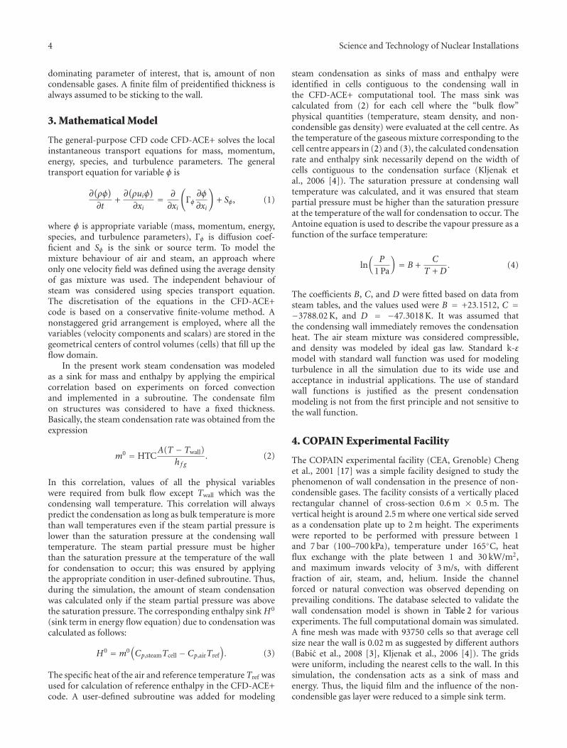
dominating parameter of interest, that is, amount of noncondensable gases. A finite film of preidentified thickness isalways assumed to be sticking to the wall.
3. Mathematical Model
The general-purpose CFD code CFD-ACE+ solves the localinstantaneous transport equations for mass, momentum,energy, species, and turbulence parameters. The generaltransport equation for variable φ is
∂(ρφ)
∂t+∂(ρuiφ
)
∂xi= ∂
∂xi
(
Γφ∂φ
∂xi
)
+ Sφ, (1)
where φ is appropriate variable (mass, momentum, energy,species, and turbulence parameters), Γφ is diffusion coef-ficient and Sφ is the sink or source term. To model themixture behaviour of air and steam, an approach whereonly one velocity field was defined using the average densityof gas mixture was used. The independent behaviour ofsteam was considered using species transport equation.The discretisation of the equations in the CFD-ACE+code is based on a conservative finite-volume method. Anonstaggered grid arrangement is employed, where all thevariables (velocity components and scalars) are stored in thegeometrical centers of control volumes (cells) that fill up theflow domain.
In the present work steam condensation was modeledas a sink for mass and enthalpy by applying the empiricalcorrelation based on experiments on forced convectionand implemented in a subroutine. The condensate filmon structures was considered to have a fixed thickness.Basically, the steam condensation rate was obtained from theexpression
m0 = HTCA(T − Twall)
h f g. (2)
In this correlation, values of all the physical variableswere required from bulk flow except Twall which was thecondensing wall temperature. This correlation will alwayspredict the condensation as long as bulk temperature is morethan wall temperatures even if the steam partial pressure islower than the saturation pressure at the condensing walltemperature. The steam partial pressure must be higherthan the saturation pressure at the temperature of the wallfor condensation to occur; this was ensured by applyingthe appropriate condition in user-defined subroutine. Thus,during the simulation, the amount of steam condensationwas calculated only if the steam partial pressure was abovethe saturation pressure. The corresponding enthalpy sink H0
(sink term in energy flow equation) due to condensation wascalculated as follows:
H0 = m0(Cp,steamTcell − Cp,airTref
). (3)
The specific heat of the air and reference temperature Tref wasused for calculation of reference enthalpy in the CFD-ACE+code. A user-defined subroutine was added for modeling
steam condensation as sinks of mass and enthalpy wereidentified in cells contiguous to the condensing wall inthe CFD-ACE+ computational tool. The mass sink wascalculated from (2) for each cell where the “bulk flow”physical quantities (temperature, steam density, and non-condensible gas density) were evaluated at the cell centre. Asthe temperature of the gaseous mixture corresponding to thecell centre appears in (2) and (3), the calculated condensationrate and enthalpy sink necessarily depend on the width ofcells contiguous to the condensation surface (Kljenak etal., 2006 [4]). The saturation pressure at condensing walltemperature was calculated, and it was ensured that steampartial pressure must be higher than the saturation pressureat the temperature of the wall for condensation to occur. TheAntoine equation is used to describe the vapour pressure as afunction of the surface temperature:
ln(
P
1 Pa
)= B +
C
T + D. (4)
The coefficients B, C, and D were fitted based on data fromsteam tables, and the values used were B = +23.1512, C =−3788.02 K, and D = −47.3018 K. It was assumed thatthe condensing wall immediately removes the condensationheat. The air steam mixture was considered compressible,and density was modeled by ideal gas law. Standard k-εmodel with standard wall function was used for modelingturbulence in all the simulation due to its wide use andacceptance in industrial applications. The use of standardwall functions is justified as the present condensationmodeling is not from the first principle and not sensitive tothe wall function.
4. COPAIN Experimental Facility
The COPAIN experimental facility (CEA, Grenoble) Chenget al., 2001 [17] was a simple facility designed to study thephenomenon of wall condensation in the presence of non-condensible gases. The facility consists of a vertically placedrectangular channel of cross-section 0.6 m × 0.5 m. Thevertical height is around 2.5 m where one vertical side servedas a condensation plate up to 2 m height. The experimentswere reported to be performed with pressure between 1and 7 bar (100–700 kPa), temperature under 165◦C, heatflux exchange with the plate between 1 and 30 kW/m2,and maximum inwards velocity of 3 m/s, with differentfraction of air, steam, and, helium. Inside the channelforced or natural convection was observed depending onprevailing conditions. The database selected to validate thewall condensation model is shown in Table 2 for variousexperiments. The full computational domain was simulated.A fine mesh was made with 93750 cells so that average cellsize near the wall is 0.02 m as suggested by different authors(Babic et al., 2008 [3], Kljenak et al., 2006 [4]). The gridswere uniform, including the nearest cells to the wall. In thissimulation, the condensation acts as a sink of mass andenergy. Thus, the liquid film and the influence of the non-condensible gas layer were reduced to a simple sink term.

Science and Technology of Nuclear Installations 5
Table 2: Parameters of the COPAIN tests.
Test no.Convective heat
transferAir velocity at inlet
(m/s)Pressure
(bar)Air temperature at inlet
(K)Wall temperature
(K)Mass fraction of
noncondensible gases
P0441 Forced 3 1.02 353.23 307.4 0.767
P0443 Free 1 1.02 352.33 300.06 0.772
P0444 Natural 0.5 1.02 351.53 299.7 0.773
P0344 Natural 0.3 1.21 344.03 322 0.864
Inlet
Condensing section
0.2250.220.2150.210.2050.20.1950.190.1850.180.1750.17
Z = 0 m
Z = 2 m
H2O
Figure 2: Steam mass fraction on the condensing wall for testP0444.
5. Results and Discussion
Figure 2 depicts the steam mass fraction on the layer of celladjacent to the condensation wall for the test P0441. Figures3, 4, 5, and 6 show the condensation flux at wall along theheight in the condensing section for all the steady states.The amount of steam condensed (numerically estimated)is slightly overestimated in the case of free convective heattransfer (P0443) experimental data by the proposed fit andproposed Nusselt (Lee corrected); however, it was in goodagreement in case of natural convection with lower velocity(P0444, P0344) and with forced convection (P0441) againstexperimental data. Use of individual empirical correlationpredicted numerical results are expectedly different as com-pared to the experimental data. The proposed fit is derivedfrom various experimental conditions and the parameterswhich reduce the uncertainty and ensure the consistentapplicability of the correlation irrespective of the parameterranges. The present fit has been derived taking a fixed value ofliquid film thickness and temperature gradient. However thiscan be improved based on specific requirement, and inputscan be generated for complex intercompartmental configu-rations within CFD framework. This result also advocatesthe replacement of simplified condensation model (lumped
0 0.5 1 1.5 2
2
3
4
5
6
7
8
9
10
11
ExperimentProposed fit
Proposed Nusselt (Lee corrected)Nusselt (UCB multiplier)Liu
Distance from the start of the condensing section (m)
Flu
x (W
/m2)
×103
Figure 3: Variation of condensation flux with height, test P0441.
0 0.5 1 1.5 2
1
2
3
4
5
6
7
8
ExperimentProposed fit
Proposed Nusselt (Lee corrected)Nusselt (UCB multiplier)Liu
Distance from the start of the condensing section (m)
Flu
x (W
/m2)
×103
Figure 4: Variation of condensation flux with height, test P0443.

6 Science and Technology of Nuclear Installations
0 0.5 1 1.5 2
1
2
3
4
5
6
7
ExperimentProposed fit
Proposed Nusselt (Lee corrected)Nusselt (UCB multiplier)Liu
Distance from the start of the condensing section (m)
Flu
x (W
/m2)
×103
Figure 5: Variation of condensation flux with height, test P0444.
0 0.5 1 1.5 20
1
2
ExperimentProposed fit
Proposed Nusselt (Lee corrected)Nusselt (UCB multiplier)Liu
Distance from the start of the condensing section (m)
Flu
x (W
/m2)
×103
Figure 6: Variation of condensation flux with height, test P0344.
parameter code-like approach) with a new improved simpleHTC in CFD-based approach which can be used to modelreal large containment geometry for safety evaluation in amore consistent manner.
6. Conclusions
A model for steam condensation was implemented andtested based on various correlations developed for volume-averaged approach in the computational fluid dynamics code
CFD-ACE+. The CFD code CFD-ACE+ was used to simu-late condensation experiments that were performed in theCOPAIN facility. There was a reasonable agreement betweensimulated and experimental results for proposed approachderived from fitting of various experimental data. Howeverfurther validations are needed against other experimentaldata. This approach does not solve the phenomenon fromthe first principle, but this approach can be considered aseffective for industrial problem where solution for large com-putational domain is required. The present work suggeststhat the approach could be used for integrated hydrogen dis-tribution/management calculation with steam condensationin nuclear reactor containment required for safety analysis.Another useful application of the present approach couldbe to obtain a first-order simplified generalized analysisresult for a containment wall surface, and subsequently dif-ferent wall surfaces can be studied in detail where specificcorrelations can be used within the CFD framework.
Nomenclature
φ: General transport variableΓφ: Diffusion coefficient for variable φSφ: Source term for variable φm0: Steam condensation rate (kg/s)ρsteam: Density of steam (kg/m3)ρnc: Density of noncondensible gases (kg/m3)A: Area of condensation surface (m2)
T : Temperature (K)Twall: Average temperature of condensation surface (K)h f g : Latent heat of steam (J/kg)H0: Enthalpy sink due to condensation (W)Cp,steam: Specific heat of steam at constant pressure (J/kgK)Cp,air: Specific heat of air at constant pressure (J/kgK)Tref: Reference temperature (K)P: Pressure (Pa)B,C,D: Constants.
References
[1] P. Royl, H. Rochholz, W. Breitung, J. R. Travis, and G.Necker, “Analysis of steam and hydrogen distributions withPAR mitigation in NPP containments,” Nuclear Engineeringand Design, vol. 202, no. 2-3, pp. 231–248, 2000.
[2] M. Houkema, N. B. Siccama, J. A. L. Nijeholt, and E. M. J.Komen, “Validation of the CFX4 CFD code for containmentthermal-hydraulics,” Nuclear Engineering and Design, vol. 238,no. 3, pp. 590–599, 2008.
[3] M. Babic, I. Kljenak, and B. Mavko, “Prediction of light gasdistribution in experimental containment facilities using theCFX4 code,” Nuclear Engineering and Design, vol. 238, no. 3,pp. 538–550, 2008.
[4] I. Kljenak, M. Babic, B. Mavko, and I. Bajsic, “Modelingof containment atmosphere mixing and stratification experi-ment using a CFD approach,” Nuclear Engineering and Design,vol. 236, no. 14–16, pp. 1682–1692, 2006.
[5] I. Kljenak, I. Bajsic, and M. Babic, “Modelling of steamcondensation on the walls of a large enclosure using a

Science and Technology of Nuclear Installations 7
Computational Fluid Dynamics code,” in Proceedings of theASME-ZSIS International Thermal Science Seminar II, Slove-nia, June 2004.
[6] H. Uchida, A. Oyama, and Y. Togo, “Evaluation of post-incident cooling systems of LWRs,” in Proceedings of the 13thInternational Conference on Peaceful Uses of Atomic Energy,pp. 93–102, International Atomic Energy Agency, Vienna,Austria, 1965.
[7] J. M. M. Valdepenas, M. A. Jimenez, F. M. Fuertes, and J.A. Fernandez, “Improvements in a CFD code for analysis ofhydrogen behaviour within containments,” Nuclear Engineer-ing and Design, vol. 237, pp. 627–647, 2007.
[8] H. Terasaka and A. Makita, “Numerical analysis of thePHEBUS containment thermal hydraulics,” Journal of NuclearScience and Technology, vol. 34, no. 7, pp. 666–678, 1997.
[9] S. Mimouni, A. Foissac, and J. Lavieville, “CFD modelling ofwall steam condensation by a two-phase flow approach,” Nu-clear Engineering and Design, vol. 241, no. 11, pp. 4445–4455,2011.
[10] S. Kudriakov, F. Dabbene, E. Studer et al., “The TONUS CFDcode for hydrogen risk analysis: physical models, numericalschemes and validation matrix,” Nuclear Engineering and De-sign, vol. 238, no. 3, pp. 551–565, 2008.
[11] CFD-ACE+ V2009.2, User Manual, ESI CFD Inc., Huntsville,Ala, USA, 2009.
[12] J. Green and K. Almenas, “An overview of the primary param-eters and methods for determining condensation heat transferto containment structures,” Nuclear Safety, vol. 37, no. 1,pp. 26–48, 1996.
[13] J. C. de la Rosa, A. Escriva, L. E. Herranz, T. Cicero, and J. L.Munoz-Cobo, “Review on condensation on the containmentstructures,” Progress in Nuclear Energy, vol. 51, no. 1, pp. 32–66, 2009.
[14] K. Y. Lee and M. H. Kim, “Experimental and empirical studyof steam condensation heat transfer with a noncondensablegas in a small-diameter vertical tube,” Nuclear Engineering andDesign, vol. 238, no. 1, pp. 207–216, 2008.
[15] M. Kawakubo, M. Aritomi, H. Kikura, and T. Komeno, “AnExperimental Study on the Cooling Characteristics of passivecontainment cooling systems,” Journal of Nuclear Science andTechnology, vol. 46, no. 4, pp. 339–345, 2009.
[16] H. S. Park, H. C. No, and Y. S. Bang, “Assessment of two wallfilm condensation models of Relap/Mod3.2 in the presence ofnoncondensable gas in a vertical tube,” Journal of the KoreanNuclear Society, vol. 31, pp. 465–475, 1999.
[17] X. Cheng, P. Bazin, P. Cornet et al., “Experimental data basefor containment thermalhydraulic analysis,” Nuclear Engineer-ing and Design, vol. 204, no. 1–3, pp. 267–284, 2001.

TribologyAdvances in
Hindawi Publishing Corporationhttp://www.hindawi.com Volume 2014
International Journal of
AerospaceEngineeringHindawi Publishing Corporationhttp://www.hindawi.com Volume 2010
FuelsJournal of
Hindawi Publishing Corporationhttp://www.hindawi.com Volume 2014
Journal ofPetroleum Engineering
Hindawi Publishing Corporationhttp://www.hindawi.com Volume 2014
Industrial EngineeringJournal of
Hindawi Publishing Corporationhttp://www.hindawi.com Volume 2014
Power ElectronicsHindawi Publishing Corporationhttp://www.hindawi.com Volume 2014
Advances in
CombustionJournal of
Hindawi Publishing Corporationhttp://www.hindawi.com Volume 2014
Journal of
Hindawi Publishing Corporationhttp://www.hindawi.com Volume 2014
Renewable Energy
Submit your manuscripts athttp://www.hindawi.com
Hindawi Publishing Corporationhttp://www.hindawi.com Volume 2014
StructuresJournal of
International Journal of
RotatingMachinery
Hindawi Publishing Corporationhttp://www.hindawi.com Volume 2014
EnergyJournal of
Hindawi Publishing Corporationhttp://www.hindawi.com Volume 2014
Hindawi Publishing Corporation http://www.hindawi.com
Journal ofEngineeringVolume 2014
Hindawi Publishing Corporation http://www.hindawi.com Volume 2014
International Journal ofPhotoenergy
Hindawi Publishing Corporationhttp://www.hindawi.com Volume 2014
Nuclear InstallationsScience and Technology of
Hindawi Publishing Corporationhttp://www.hindawi.com Volume 2014
Solar EnergyJournal of
Hindawi Publishing Corporationhttp://www.hindawi.com Volume 2014
Wind EnergyJournal of
Hindawi Publishing Corporationhttp://www.hindawi.com Volume 2014
Nuclear EnergyInternational Journal of
Hindawi Publishing Corporationhttp://www.hindawi.com Volume 2014
High Energy PhysicsAdvances in
The Scientific World JournalHindawi Publishing Corporation http://www.hindawi.com Volume 2014