computed radiography chapter 3 physics and …radpacs.weber.edu/images/r_christensen/radt...
TRANSCRIPT

9/8/2015
1
This presentation is a professional collaboration of
development time prepared by:
Rex Christensen
Terri Jurkiewicz
and
Diane Kawamura
Computed Radiography
Chapter 3
Physics and Technology
Today’s Humor: More Medical Anomalies
What is Computed Radiography?
Or what is CR?
It is x-rays passing thru the patient
being picked up by a digital detector.
Photostimulable luminescence (PSL) is
seen due to phosphors being excited by
the x-rays.
Other names for CR are SPR storage
phosphor radiography and DSP digital
storage phosphor radiography
CR Technology
The Imaging plate
The imaging reader
The display

9/8/2015
2
History
1983 CR started being used for
diagnostic radiography.
Fuji started with FCR 101 followed by
Kodak, and Agfa.
Now there are four manufacturers with
the addition of Konica.
Imaging System . . . . . . .
Four Steps:
1. Image Acquistion
2. Image plate
scanning and erasure
3. Image processing
4. Image display
+ implementation issues:
Use of grids, radiation exposure,
and technique selection.
PSP
The photostimulable phosphor on the
imaging plate must have good
absorption efficiency of x-rays and
must be stimulated by a helium-neon
laser.
It must also be compatible with the
photomultiplier tube and luminescence
must be shorter the 1 microsecond.
Phosphors must be able to store the
latent image for several hours without
compromising the signal from the IP
Phosphors
Phosphors meeting the above criteria are:
Barium Fluoro Halide:Europium
Halide can be chlorine, bromine, or
iodine or a mixture of them.
The phosphor is usually doped with
Europium because it is an activator
which increases the efficiency of the
PSL.

9/8/2015
3
Latent Image Formation
Electrons move from a ground state to
the higher energy state when the
europium atoms are bombarded by x-
rays.
The x-ray’s travel to the F-Center (F
comes from farbe meaning color)
The number of trapped electrons are
equal to the absorbed radiation.
PHOTOSTIMULABLE LUMINESCENCE
Compton and
photoelectric x-ray
interactions occur with
outer-shell electrons
Outer-shell electrons
are sent into an
excited, metastable
state
X-ray interaction with a
photostimulable
phosphor results in
excitation of electrons
into a metastable state.
PHOTOSTIMULABLE LUMINESCENCE
Over time, the
metastable electrons
return to the ground
state on their own
When metastable
electrons return to
their ground state,
visible light is emitted.
PHOTOSTIMULABLE LUMINESCENCE
Exposing the phosphor to intense infrared light
from a laser accelerates or stimulates the
process of the electrons returning to the ground
state.

9/8/2015
4
PHOTOSTIMULABLE LUMINESCENCE
The storage phosphor screen appears white
because the small photostimulable phosphor
particles scatter light excessively
• Turbid is the term used to describe the excessive
scattering of light
The photostimulable phosphor particles are
randomly positioned throughout the binder
Laser Light
The lasers today
are semiconductor
lasers that produce light
with a 680nm
wavelength,
compared to the
older He Ne lasers
that produce light at
633nm which was used
in the earlier CR units.
Computer Radiography (CR)
plate is photostimulable phosphor
radiation traps electrons in high energy states
higher states form latent image
H i g h e r E n e r g y
E l e c t r o n
S t a t e
L o w e r E n e r g y
E l e c t r o n
S t a t e
-
-
-
-
-
-
-
-
-
-
-
-
-
-
-
-
-
-
-
-
-
-
-
-
-
-
-
X - R a y
P h o t o n
-
P h o t o n p u m p s
e l e c t r o n t o
h i g h e r e n e r g y s t a t e
Reading Imaging Plate reader scans plate
with laser
laser releases electrons trapped in high energy states
electrons fall to low energy states
electrons give up energy as visible light
light intensity is measure of incident radiation
Laser Beam
Higher Energy
Elect ron
St at e
Lower Energy
Elect ron
St at e
-
-
-
-
-
-
-
-
-
-
-
-
-
-
-
-
-
-
-
-
-
-
-
-
-
-
-
-
Lower Energy
Electron State

9/8/2015
5
Fluoroescent Bulbs Erase the Plate
The IP plate is erased using high intensity
light to remove residual energy.
Analog to Digital Image
The light emission is then collected by a
collection device and sent to the
photomultiplier tube which then
produces an electrical signal, it is
digitized by the ADC and sent to the
computer for processing.
Fading
This is the time it takes for a latent
image to disappear.
That is why it is important to have the
image plate “read” as soon as possible
after the exposure.
The PSL decreases by 25% within 8
hours between exposure and reading.
PSP Layers
A high resolution PSP layer is thinner
than the standard resolution layer, and
has a sharper image due to less lateral
spread of the laser light.
The thicker phosphor layer IP’s have
faster speed than the high resolution
IP’s.
High resolution IP’s will be used for
small parts to increase the resolution.

9/8/2015
6
The plate consists of:
A PSP layer on a base for support.
Two protective layers
Electroconductor layer
Light shielding layer.
Film Screen vs. IP Layers
The purpose of the electroconductive
layer is to reduce any static electricity
problems when the IP is transported
into the reader.
Imaging Plates
Housing the imaging plate is a
lightweight aluminum or aluminum
honeycomb panel on the back which is
designed to prevent backscatter
radiation, and a radiolucent front.

9/8/2015
7
Scanning the IP
There are two main types of scanning
mechanisms:
1. Point Scan Reader
2. Line Scan Reader
Seeram P. 55
Bushong P. 419-421
Workstation
Allows:
Input of patient information
Region of exposure
Image preview
Image processing
Quality assurance
Image printing
Sending images to PACS
Workstation
Consists of :
Processing computer
Monitor (CRT or LCD)
Keyboard
Mouse
Some may have
barcode readers and
magnetic card reader.
Digital Image Processing
Picture is of colliding galaxies taken from Hubble telescope

9/8/2015
8
Pre-Processing Operations
Pre-processing is necessary to make
corrections on the data received from
the imaging plate.
1. Exposure field recognition: This
pertains to the size of the field of view.
That is why centering, and collimation is
so important.
Histogram
2. Histogram analysis- the computer
analyzes the exposure field and makes
an analysis of what was imaged. So if it
was centered incorrectly the image will
be light or dark.
Measured histogram is the actual
histogram of the image taken
Stored histogram is the predetermined
histogram for the study (ie forearm
predetermined average histogram.
Histogram
A histogram is a graph of the number of pixels in
the entire image or part of the image having the
same gray levels (density values) plotted as a
function of the gray levels
Grayscale Rendition
3. Grayscale rendition- It is the determination
of the minimum and maximum penetration
and sets the luminance presentation
according to those values obtained during the
exposure.
This is where the look up table comes into
play.

9/8/2015
9
Exposure Recognition
It is the visual indicator for the
technologist letting him/her know
whether the exposure was appropriate.
This can be used as a form of quality
control to optimize the quality of the
image and limit the exposure rate to the
patient.
Exposure Indicators
Fuji Medical- Sensitivity number (S
number)
Agfa Medical- log of Median (lgM)
Kodak-Exposure Index (EI)
They each use a different name for the
same thing – this is the exposure
recognition indicator.
Post Processing
These enable the technologist or
radiologist to manipulate the image to
optimize it for viewing purposes.
Increase/decrease contrast-brightness,
sharpen the image, smooth the image,
enlarge an area, lighten or darken the
image, remove the bone, or soft tissue.
All of this is possible with post
processing.
Edge Enhancement - Smoothing

9/8/2015
10
Contrast Manipulation
W 226
W 100 W 500
- =
Post-contrast Image Pre-contrast Image - Mask
Subtraction Image
Contrast Enhancement
Accomplished by windowing Window width encompasses the range of
densities within an image
A narrow window is comparable to the use of a high-contrast radiographic film
Image contrast is increased
A narrow window is valuable when subtle difference in subject density need to be better visualized
Narrow window increases image noise and the densities outside of the narrow window are not visualized
Digital Imaging Processing

9/8/2015
11
Contrast Enhancement
Increasing the width of the window allows
more of the gray scale to be visualized or
more latitude in the densities of the image
Digital Imaging Processing
Windowing
Windowing is a digital image processing
technique that also changes the contrast and
brightness of an image.
The illustration shows the range of pixel values
(gray levels) and displayed image contrast range
on a digital image.
Windowing
A digital image is made up of numbers.
• The range of number is the window width
(WW)
• The center of the range is defined as the
window level (WL).
The WW controls image contrast.
The WL controls the brightness.
Windowing
The displayed WW and
WL values are always
shown on the image.
Narrow WW provides
higher image contrast
(short-scale contrast) and
a wide WW will show an
image with less contrast.

9/8/2015
12
Windowing
• If the WL is increased, the
image becomes darker
since more of the lower
numbers will be displayed.
Exposure Indicators
It is a numerical value that is used to
demonstrate the exposure.
As previously state the different
companies use different indicators.
S-Number
EI (exposure indicator)
LgM (log of median values)
EI Guidelines for Quality Control
The challenge is to minimize the
radiation exposure to the patient, while
maintaining optimal exposure image
quality.
The exposure indicator is what allows
the technologist to accomplish this.
Spatial Resolution
Size of the pixels help to determine the
resolution
of an image
. The smaller
the pixels the
better the
resolution.

9/8/2015
13
Resolution
One pixel
The number of pixels in a given area
defines the resolution of an image
1”
500 x 1,000 pixels http://escholarship.cdlib.org/rtennant/presentations/2002bcla/16
Dynamic Range (bit-depth)
1 bit 8 bit grayscale 8 bit color 24 bit color
(GIF) (GIF) (JPEG)
1 bit = black or white
8 bits = 256 shades
16 bits = thousands
24 bits = millions
36 bits = billions http://escholarship.cdlib.org/rtennant/
presentations/2002bcla/17
The bit depth has an effect on the number of
shades of gray, hence the density resolution of
the image.
Noise
Electronic Noise (System): You cannot
control the system noise, it is inherent in
the machine.
Quantum Mottle (noise): This is
determined by the number of photons
hitting the detector. When the number
of photons is too low there is more
noise, and the reverse high number of
photons lower noise.

9/8/2015
14
Modulation Transfer Function MTF is the spatial frequency response of an
imaging system or a component; it is the contrast at a given spatial frequency relative to low frequencies.
Spatial frequency is typically measured in cycles or line pairs per millimeter (lp/mm)
High spatial frequencies correspond to fine image detail. The more extended the response, the finer the detail-- the sharper the image.
Digital Imaging Processing DQE
Detective Quantum Efficiency-
The detector receives the exposure
converting it to an image. The DQE is a
measurement of the efficiency in which
the detector performs this task.
It includes the signal to noise ratio and
the system noise in the value. You want
no loss of information.
Perfect detector is 1 or 100%
Artifacts
Digital artifacts come from many
sources.
Hardware, software, and objects
imaged.
Many artifacts arise from the imaging
plate –it is handled frequently, and
should be cleaned often.
Incorrect storage of IP and use of grids.
CR reader is another source of artifacts.
Poor Screen Cleaning
9/8/2015
15
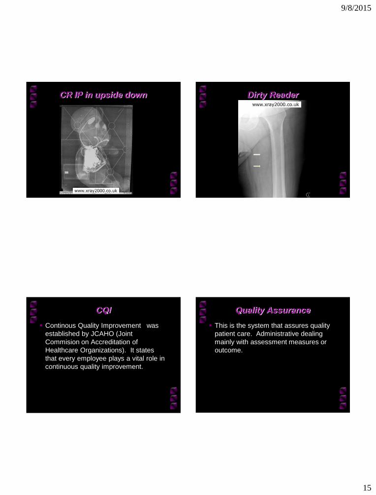
CR IP in upside down
Dirty Reader
CQI
Continous Quality Improvement was
established by JCAHO (Joint
Commision on Accreditation of
Healthcare Organizations). It states
that every employee plays a vital role in
continuous quality improvement.
Quality Assurance
This is the system that assures quality
patient care. Administrative dealing
mainly with assessment measures or
outcome.

9/8/2015
16
Quality Control
This is technical aspect dealing mainly
with the quality and maintenance of
equipment and dose to the patient.
The point of CQI, QA and QC is to
maintain and improve the quality of
service, dose, images, and diagnosis of
the patient all at the lowest cost
possible.
Test Tools for CR
Inspect the Imaging Plate
Test the monitor for resolution, contrast,
brightness, linearity, collimation, etc.
Wire mesh can be used for contact,
antiscatter grid, densitometer for hard
copy images, and phantoms
The End of Chapter 3
Picture of Earth from
Hubble telescope
Thanks to
http://www.ceessenti
als.net/article11.html
for some of the images
obtained in this ppt.