computer-aided design (cad) for integrated
TRANSCRIPT

AFRL-IF-RS-TR-2002-176 Final Technical Report August 2002 COMPUTER-AIDED DESIGN (CAD) FOR INTEGRATED MICROELECTROMECHANICAL (MEMS) DEVICES Analog Devices, Incorporated Sponsored by Defense Advanced Research Projects Agency DARPA Order No. E117
APPROVED FOR PUBLIC RELEASE; DISTRIBUTION UNLIMITED.
AIR FORCE RESEARCH LABORATORY INFORMATION DIRECTORATE
ROME RESEARCH SITE ROME, NEW YORK

This report has been reviewed by the Air Force Research Laboratory, Information Directorate, Public Affairs Office (IFOIPA) and is releasable to the National Technical Information Service (NTIS). At NTIS it will be releasable to the general public, including foreign nations. AFRL-IF-RS-TR-2002-176 has been reviewed and is approved for publication
APPROVED: ROBERT HILLMAN Project Engineer
FOR THE DIRECTOR: MICHAEL L. TALBERT, Technical Advisor Information Technology Division Information Directorate
REPORT DOCUMENTATION PAGE Form Approved OMB No. 074-0188
Public reporting burden for this collection of information is estimated to average 1 hour per response, including the time for reviewing instructions, searching existing data sources, gathering and maintaining the data needed, and completing and reviewing this collection of information. Send comments regarding this burden estimate or any other aspect of this collection of information, including suggestions for reducing this burden to Washington Headquarters Services, Directorate for Information Operations and Reports, 1215 Jefferson Davis Highway, Suite 1204, Arlington, VA 22202-4302, and to the Office of Management and Budget, Paperwork Reduction Project (0704-0188), Washington, DC 20503 1. AGENCY USE ONLY (Leave blank)
2. REPORT DATEAUGUST 2002
3. REPORT TYPE AND DATES COVERED Final Sep 96 – Sep 01
4. TITLE AND SUBTITLE COMPUTER-AIDED DESIGN (CAD) FOR INTEGRATED MICROELECTROMECHANICAL (MEMS) DEVICES
6. AUTHOR(S) Michael Judy
5. FUNDING NUMBERS C - F30602-96-2-0290 PE - 63739E PR - E117 TA - 00 WU - 06
7. PERFORMING ORGANIZATION NAME(S) AND ADDRESS(ES) Analog Devices, Incorporated 21 Osborne Street Cambridge Massachusetts 02139
8. PERFORMING ORGANIZATION REPORT NUMBER
N/A
9. SPONSORING / MONITORING AGENCY NAME(S) AND ADDRESS(ES) Defense Advanced Research Projects Agency AFRL/IFTC 3701 North Fairfax Drive 26 Electronic Parkway Arlington Virginia 22203-1714 Rome New York 13441-4514
10. SPONSORING / MONITORING AGENCY REPORT NUMBER AFRL-IF-RS-TR-2002-176
11. SUPPLEMENTARY NOTES AFRL Project Engineer: Robert Hillman/IFTC/(315) 330-4961
12a. DISTRIBUTION / AVAILABILITY STATEMENT APPROVED FOR PUBLIC RELEASE; DISTRIBUTION UNLIMITED.
12b. DISTRIBUTION CODE
13. ABSTRACT (Maximum 200 Words) The objective of this “CAD FOR Integrated MEMS Devices” research project was to develop MEMS CAD design and development tools that would facilitate the creation of behavioral models for complex MEMS devices. More complex and capable MEMS devices are becoming a reality to extend out country’s technological leadership in military and commercial electronics, which in turn would help maintain our military superiority. To this end, the project focused on creating a uniform design environment for the design and simulation of high-performance, complex integrated MEMS systems. The initial activity focused primarily on the MEMS systems design, however it became clear that incorporating integrated circuit simulations with the MEMS behavioral models was a priority. This provided more accurate simulations of the integrated MEMS systems as well as the environment they were intended to operate within. The resulting design environment provides the designer with an increased likelihood of functional first silicon. High performance MEMS devices such as accelerometers and gyros require the MEMS, circuits and their interactions to be fully simulated – primarily because MEMS devices exhibit fundamentally more complex interactions than those required in conventional electronic CAD.
15. NUMBER OF PAGES44
14. SUBJECT TERMS Microelectromechanical, Computer-Aided Design, MEMS CAD, MEMS Behavioral Models, Integrated MEMS Design, MEMS System Design 16. PRICE CODE
17. SECURITY CLASSIFICATION OF REPORT
UNCLASSIFIED
18. SECURITY CLASSIFICATION OF THIS PAGE
UNCLASSIFIED
19. SECURITY CLASSIFICATION OF ABSTRACT
UNCLASSIFIED
20. LIMITATION OF ABSTRACT
ULNSN 7540-01-280-5500 Standard Form 298 (Rev. 2-89)
Prescribed by ANSI Std. Z39-18 298-102

i
Table of Contents
1 Technical Achievements............................................................................................. 1
1.1 Objective ............................................................................................................. 1 1.1.1 Initial Objective .......................................................................................... 1 1.1.2 Final Objective............................................................................................ 3 1.1.3 Note on Microcosm versus Coventor ......................................................... 3
1.2 Major Accomplishments..................................................................................... 4 1.2.1 Executive Summary .................................................................................... 4 1.2.2 Saber Based MEMS Cadtool Development: MEMCAD ....................... 5
1.2.2.1 AutoMM .............................................................................................. 6 1.2.2.2 Cosolve-LEM: Improvements and Enhancements ................................. 9 1.2.2.3 Parametric Electro-Mechanical (PEM) Library.................................... 12 1.2.2.4 Schematic to Layout Creation............................................................... 13
1.2.3 Spice Based MEMS Cadtool Developments ............................................ 15 1.2.3.1 Mechanical schematic (ADICE/SPICE based models) ........................ 15 1.2.3.2 Verification of MEMS: DRC & LVS ................................................... 19
1.2.3.2.1 MemsXView................................................................................... 19 1.2.3.2.2 Memsdbx......................................................................................... 20 1.2.3.2.3 MemsCheck .................................................................................... 20
1.2.3.3 Modification of Autobem tool for Macromodeling .............................. 20 1.2.4 Application of New Tools in Real Designs .............................................. 25
1.2.4.1 ADXL190 ............................................................................................. 25 1.2.4.2 ADXL78 ............................................................................................... 27 1.2.4.3 SPCMems – Modeling Process Corners ............................................... 27
1.2.5 Uniform Design Environment for Integrated MEMS............................... 29 1.3 Summary ........................................................................................................... 34 1.4 Publications....................................................................................................... 35
2 Business/Financial Aspects of the Agreement.......................................................... 36 2.1 Total Costs Incurred.......................................................................................... 36
2.1.1 Estimated Cost per Contract ..................................................................... 38 2.1.2 Final Actual Costs per Vouchers .............................................................. 38
ii
List of Figures Figure 1: MEMS CAD program tasks. ............................................................................... 2 Figure 2: Outline of AutoMM process: Start with solid model of MEMS device.
Simulate over a large space of deformations and curve-fit the results. The results are included as elements in a Saber based reduced order representation. ........................ 6
Figure 3: Comparison of AC response of AutoMM generated macromodel with full 3-D FEM simulation. Tethered plate – modal frequencies. Micromirror – static coupled electro-mechanics. ...................................................................................................... 8
Figure 4: Comparison of pull-in analysis of AutoMM 6-DOF macromodel with full 3-D coupled FEM. The pull-down electrode was located under the lower-left corner of the tethered plate. A) z- displacement, B) y-rotation, C) x-rotation. ......................... 9
Figure 5: Simulation of highly complex MEMS devices in MEMCAD: ADXL76 and a ring gyro.................................................................................................................... 10
Figure 6: Predicted and observed frequency shifts for the resonant beam. Error bars show sensitivity to gap variation of ±6% around a gap of 0.08µm.................................... 11
Figure 7: Automatic creation layout from a Saber schematic........................................... 14 Figure 8: ADXL76 mechanical schematic (2 DOF) implemented in Cadence using Spice
models for each individual component. .................................................................... 16 Figure 9: Response of mechanical schematic model of ADXL78 accelerometer to a
2000g overload. Demonstrates the implementation of nonlinear damping. ............ 18 Figure 10: Macromodeling using AutoBEM - warpage of ADXL76 accelerometer and
resulting charge distribution. .................................................................................... 22 Figure 11: Batch language of Autobem showing implementation of the deform
command which allows the geometry to be deformed by a generic mathematical transformation. See AutoBEM manual for a detailed description........................... 24
Figure 12: ADXL190 - 250g version of ADXL76 with sense and force capacitor fingers swapped..................................................................................................................... 25
Figure 13: Results from application of MEMCAD tools to ADXL190. Curvature impact on sensitivity (Kp). Sensitivity trim of SiCr resistors was 10% lower. ................... 26
Figure 14: SPCMems – tether spring constant variation. ................................................. 28 Figure 15: SPCMems - tether mismatch. Creates unintended cross-axis effects. ........... 28 Figure 16: SPCMems - misalignment of tether anchor. Very useful for exploring
packaging effects. ..................................................................................................... 29 Figure 17: Example of a gyro using MEMCAD models applied in a Cadence design
environment. The properties of the electrode element are shown on the right....... 30 Figure 18: ADXL76 implemented using PEM library parameters in the Cadence
environment. The properties of the 1 segment beam element are shown on the right.................................................................................................................................... 31
Figure 19: Example of SpectreRF interface to macromodels in Cadence design environment - Gyroscope.......................................................................................... 32

iii
List of Tables
Table 1: Validation criteria. .............................................................................................. 33

1
1 Technical Achievements
1.1 Objective
As often happens with long term programs the initial objectives and motivations
evolved during the course of the MEMS CAD program. While the objectives did shift,
the shift was more an expansion of the goals to increase the impact of this program to the
MEMS design community as well as more fully realize the initial intension – MEMS
CAD tools for highly complex, integrated MEMS systems.
1.1.1 Initial Objective
The initial objective of this project was to develop MEMS CAD design and
development tools that would facilitate the creation of behavioral models for complex
MEMS devices. More complex and capable MEMS devices were becoming required to
extend our country’s technological leadership in military and commercial electronics,
which in turn would help maintain our military superiority. At that time no means was
available to rapidly and accurately design integrate MEMS systems.
High performance MEMS devices such as accelerometers and gyros require the
MEMS, circuits and their interactions to be fully simulated – primarily because MEMS
devices exhibit fundamentally more complex interactions than those required in
electronic CAD. These interactions are so complex that behavioral models were
required; however, accurate behavioral models were not available in MEMS CAD tools
at the beginning of this program.
2
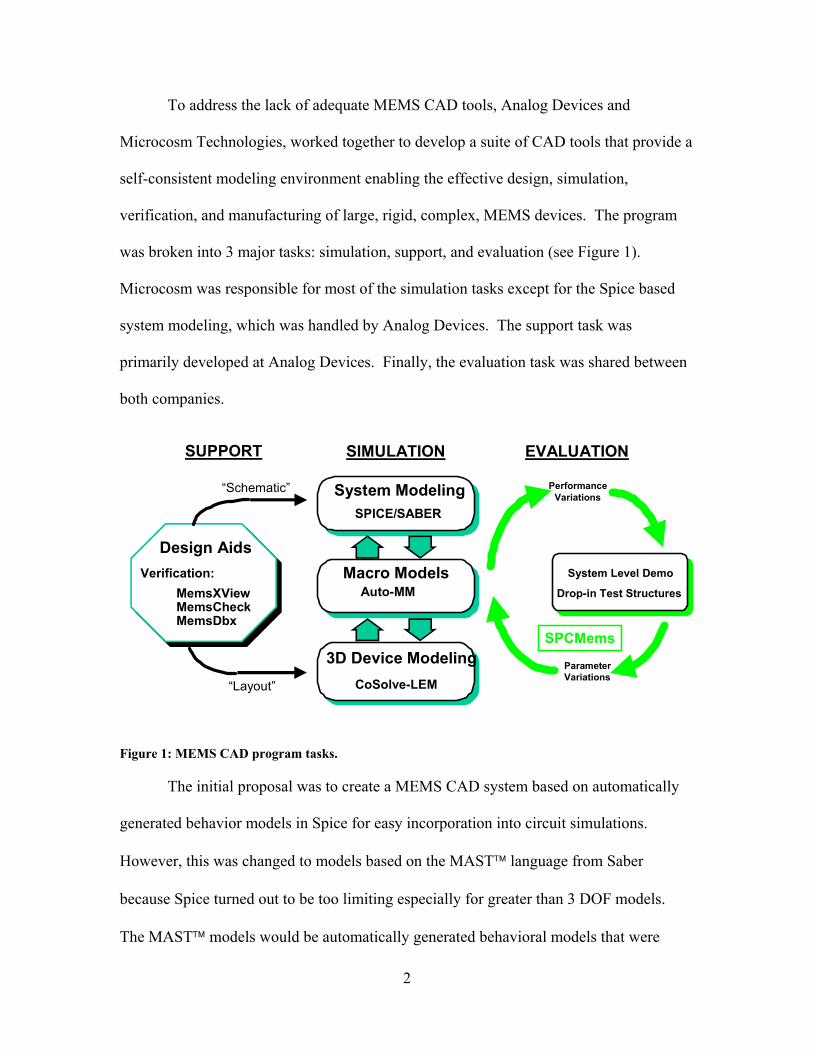
To address the lack of adequate MEMS CAD tools, Analog Devices and
Microcosm Technologies, worked together to develop a suite of CAD tools that provide a
self-consistent modeling environment enabling the effective design, simulation,
verification, and manufacturing of large, rigid, complex, MEMS devices. The program
was broken into 3 major tasks: simulation, support, and evaluation (see Figure 1).
Microcosm was responsible for most of the simulation tasks except for the Spice based
system modeling, which was handled by Analog Devices. The support task was
primarily developed at Analog Devices. Finally, the evaluation task was shared between
both companies.
Design AidsVerification:
MemsXViewMemsCheckMemsDbx
“Schematic”
“Layout”
SUPPORT
3D Device Modeling
Macro Models
System Modeling
Auto-MM
CoSolve-LEM
SPICE/SABER
SIMULATION
SPCMems
PerformanceVariations
ParameterVariations
System Level Demo
Drop-in Test Structures
EVALUATION
Figure 1: MEMS CAD program tasks.
The initial proposal was to create a MEMS CAD system based on automatically
generated behavior models in Spice for easy incorporation into circuit simulations.
However, this was changed to models based on the MAST language from Saber
because Spice turned out to be too limiting especially for greater than 3 DOF models.
The MAST models would be automatically generated behavioral models that were

3
created from coupled mechanical finite element and electrostatic boundary element
simulations.
1.1.2 Final Objective
During the course of this program the object expanded to create a uniform design
environment for the design and simulation of high-performance, complex integrated
MEMS systems. The stress was on “integrated MEMS” and primarily refers to the shift
from Saber as the base HDL simulation tool to a Cadence/Spectre interface. While
the initial objective focused primarily on the MEMS system design, it became
increasingly clear that incorporating the integrated circuit simulations with the MEMS
behavioral models was a priority. This would provide more accurate simulations of
integrated MEMS systems as well as increase the likelihood of functional first silicon.
Cadence/Spectre is a much more widely used electronic CAD package for
integrated circuit design so this was felt to be more relevant to the general integrated
MEMS community. Saber was initially not designed as a circuit simulator like Spectre,
it was designed as a high level system simulator. This made Saber perfectly matched
for the initial objective of a MEMS focused design flow, but ill suited to a higher-level
integrated system design flow.
1.1.3 Note on Microcosm versus Coventor
During the course of this program Microcosm changed the company name to
Coventor. Correspondingly the name of their software package was also changed from
MEMCAD to CoventorWare. Both names are used throughout this report, but refer
to the same essential tools and code.

4
1.2 Major Accomplishments
1.2.1 Executive Summary
This program met almost all of its objectives. MEMS CAD tools were produced
to create automatic behavioral models that were derived from FEM and BEM simulations
of MEMS devices. The resulting software was made available to the MEMS community
through the MEMCAD suite of tools. The MEMCAD tools are based on a Saber
HDL simulation engine, which is well adapted for system level simulations (specifically
MEMS). The program was divided in to three tasks: simulation, support and evaluation.
The primary accomplishments of the simulation task were the creation of AutoMM,
which automatically generates 6 DOF macromodels, the improvement of the Cosolve-
EM engine inside MEMCAD to solve large real world MEMS devices, the initial
formation of the parameterized electro mechanical (PEM) behavioral model library (top-
down design flow), and the implementation of a schematic to layout creation feature.
The support or verification task produced some useful design aids around a
Cadence design environment: a symmetry/mass and connectivity checker. However, the
initial goal of producing a full mechanical layout versus schematic (LVS) implementation
was not achieved. An alternative approach was produced though that was based on a top-
down design flow where the layout was generated from a schematic representation of the
MEMS device (PEM library based).
In the evaluation task the new MEMS CAD system was applied to real world
design problems: the ADXL190 and ADXL78. In addition, a series of test structures were
designed and applied to several processes; however, a SPCMems tool was not developed.
5
Instead, AutoMM and the parameterized electromechanical library (PEM) allowed the
user to explore the design space sensitivity to manufacturing variations such as beam
width and curvature.
Towards the end of the project the resulting AutoMM and PEM models were
ported from Saber/MAST to the Cadence/SpectreRF simulation environment. This
was felt to be more useful for the general integrated MEMS community for the
simulation of circuits with behavioral MEMS models. The Cadence environment
produces accurate top-level circuit/MEMS simulations and should improve first silicon
success because all complexities of the integrated MEMS design can be included (e.g.
highly complex MEMS behavior as well as parasitic capacitance and resistance effects).
The major accomplishments of this program are organized into four categories:
• Saber based MEMS CAD tools – Simulation and Support Tasks • Spice based MEMS CAD tools – Simulation and Support Tasks • Successful applications of newly developed CAD tools – Evaluation Task • Uniform design environment for MEMS and integrated circuits in the Cadence
environment – Verilog-A models Each of these accomplishments is described the following sections.
1.2.2 Saber Based MEMS Cadtool Development: MEMCAD
Four different tools/features in MEMCAD can attribute much of their existence
to this program. MEMCAD has evolved into CoventorWare in which all of the
software products have been transferred and are available today. Most of the features
described below were made available with the release of MEMCAD 4.0 in 1999.

6
1.2.2.1 AutoMM
AutoMM was the first MEMS CAD tool to automatically extracts 6 DOF
electro-mechanical reduced order models from a solid model representation of a MEMS
device. This is also known as a bottoms-up design flow and has been used quite
extensively in MEMS prior to this program, albeit in a manual mode. While 6 DOF
macromodels can be generated the user can choose lower DOFs. This will greatly
decrease the time required to create the macromodel. AutoMM was initially released as
part of MEMCAD, but is now available in CoventorWare/Builder.
The method of AutoMM is outlined in Figure 2. First, the user generates a solid
model from a layout and a process description file. Next, the user instructs AutoMM to
Extract from 3D simulations:Auto-Fit of Behavior
Curves– Mechanical Spring– Electrostatic Forces– Mass– Damping Coefficients
• Auto generation of up to 6-DOF macro-models
• Netlisting in industry standard HDL (MAST) and simulation tool (Saber)
Figure 2: Outline of AutoMM process: Start with solid model of MEMS device. Simulate over a large space of deformations and curve-fit the results. The results are included as elements in a Saber based reduced order representation.
riot or Simulation ."« Hotel»*' Dot« of Sprlx
Sl«ilill«i »at.
Kolli Ho>m ?••■« *••!» El . . •
7
extract the spring, mass, damper or electrode macromodels of a given MEMS device,
which is a accomplished through the corresponding FEM/BEM simulations including
coupled domain simulations. The user is required to specify the boundary conditions of
the solid model, the locations of loads and the range of desired deformations. A very
large number of FEM/BEM simulations are required to curve fit the resulting responses
to an acceptable level, but this is dependent on the desired number of degrees of freedom.
The resulting macromodel is then made available for incorporation into any MAST
HDL schematic. It is important to point out that each individual component (e.g. spring,
electrode) must be independently extracted via AutoMM. The idea isn’t to generate a
complete model of the entire device at once, but to break the macromodeling problem
down to the individual components that can then be incorporated into a top-down
simulation. A highly complex suspension is a good example of an AutoMM problem.
Instead of using dozens or more beam PEM elements, the macromodel of the entire
suspension can be extracted and substituted for all of the PEM elements. In addition to
making the schematic much easier to understand it also speeds up the simulation in
Saber.
Since FEM/BEM simulations of complex MEMS devices are relatively slow it
was imperative to improve the efficiency of the macromodel extraction. Two methods
were implemented to speed up extraction. First, a latin hypercube sampling algorithm
was tried, but while this method did improve efficiency it did not go far enough to allow
AutoMM to tackle real-world problems like the ADXL76 accelerometer, which was
one of the key goals of this project. The second method for numerical evaluation of a
model for macromodel extraction was a stratified random sampling algorithm (SRS).
8
This improved extraction speed by a factor of 10-30x. Finally, to improve the accuracy
of the resulting macromodels the curve fitting function class was expanded from
polynomials to rational functions. This also helped reduce the number of points that were
required for extraction, especially where large deformation effects become significant.
To verify the macromodels the same solid models were simulated with a full 3-D
FEM simulation tool and the results compared with the Saber AutoMM macromodel
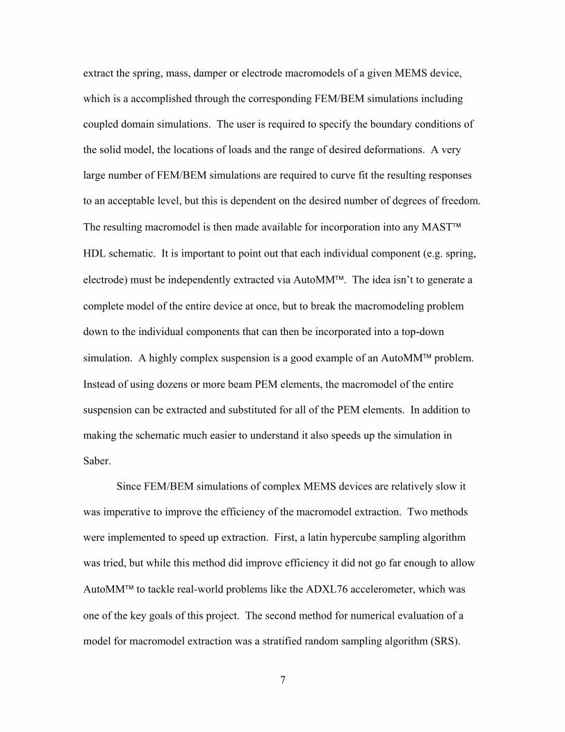
results. Figure 3 shows two different geometries that were compared: a tethered plate
and a micromirror. The results match very well to the full 3-D FEM simulations with
typically a few percent difference between the macromodel and FEM results.
25 Volts 150 Volts DOF F3D AM %E F3D AM %E
Tz (nm) -1.60 -1.56 2.5 -65 -60 7.7 Rx (µ rad) 2.526 2.46 1 102.5 89.6 12.6 Ry (µ rad) 40.95 39.5 3.5 1700 1550 8.8
D e g re e s o f F re e d o m A u to M M F u ll 3 -D % E rro rT ra n s la tio n a l X 5 9 3 .2 K 5 8 3 .5 K + 1 .6 6 T ra n s la tio n a l Y 3 0 3 4 .0 K 3 0 7 0 .8 K -1 .2 0 T ra n s la tio n a l Z 2 9 7 .4 K 3 0 4 .8 K -2 .4 4 R o ta tio n a l X 6 7 2 .5 K 6 6 4 .2 K + 1 .2 6 R o ta tio n a l Y 1 6 9 .0 K 1 6 5 .4 K + 2 .2 1 R o ta tio n a l Z 1 1 1 1 .3 K 1 1 3 8 .3 K -2 .3 7
• Tethered plate
• Micromirror
Figure 3: Comparison of AC response of AutoMM generated macromodel with full 3-D FEM simulation. Tethered plate – modal frequencies. Micromirror – static coupled electro-mechanics.
The tethered plate AutoMM macromodel was also used to verify the pull-in
response of the macromodel with full 3-D coupled FEM simulations. It should be noted
-^pr-

9
that the full 3-D coupled FEM simulations took ~100x longer to run. In this case there
were four electrodes under the central mass, but only the lower left electrode had the
voltage applied to it. As can be seen in Figure 4 the results agree very well.
Vertical displacements
-0.5
-0.45
-0.4
-0.35
-0.3
-0.25
-0.2
-0.15
-0.1
-0.05
00 100 200 300 400
Voltage, V
Uz,
um 3D FEM6 DOF Micromodel
Rotational DOF
0
0.0001
0.0002
0.0003
0.0004
0.0005
0.0006
0.0007
0.0008
0 100 200 300 400
Voltage, V
Rx,
rad
3D FEM6 DOF Micromodel
Rotational DOF
0
0.0002
0.0004
0.0006
0.0008
0.001
0.0012
0.0014
0 100 200 300 400
Voltage, V
Ry,
rad 3D FEM
6 DOF Micromodel
A)
B) C)
Figure 4: Comparison of pull-in analysis of AutoMM 6-DOF macromodel with full 3-D coupled FEM. The pull-down electrode was located under the lower-left corner of the tethered plate. A) z- displacement, B) y-rotation, C) x-rotation.
1.2.2.2 Cosolve-LEM: Improvements and Enhancements
Cosolve-LEM solves problems in the electrostatic and mechanical domains by
iterating between optimized solvers for each domain. The mechanical solver is finite
element (FEM) based and is well understood. The electrostatic solver (MemCap) is a
boundary element solver (BEM) and was the focus of the effort in this project because
the electrostatic problems are often much larger than the corresponding mechanical

10
problems. Two separate meshes are created from the initial solid model, one FEM and
one BEM. The two meshes are connected by sharing common vertices. This transfers
the deformations between the two solvers.
To improve MemCap a pre-corrected FFT based algorithm was implemented.
This added the ability to handle various Green’s functions (e.g. ideal ground plane
boundary conditions) and demonstrated better computational performance for most
MEMS structures such as accelerometers. Memory management was also improved thus
allowing the solution of up to 140,000 panel problems (Figure 5).
• ADXL76 accelerometer
• Ring Gyro
Figure 5: Simulation of highly complex MEMS devices in MEMCAD: ADXL76 and a ring gyro.
In addition to improving the core MemCap solver several other enhancements
were implemented. First, a tool was added for modeling resonant frequency shifts due to
11
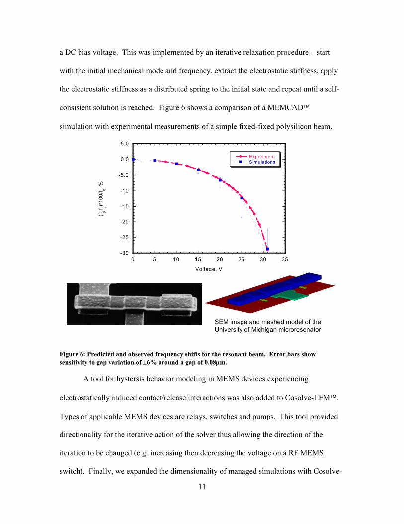
a DC bias voltage. This was implemented by an iterative relaxation procedure – start
with the initial mechanical mode and frequency, extract the electrostatic stiffness, apply
the electrostatic stiffness as a distributed spring to the initial state and repeat until a self-
consistent solution is reached. Figure 6 shows a comparison of a MEMCAD
simulation with experimental measurements of a simple fixed-fixed polysilicon beam.
-30
-25
-20
-15
-10
-5.0
0.0
5.0
0 5 10 15 20 25 30 35
ExperimentSimulations
(f 0-f v)*10
0/f 0, %
Voltage, V
SEM image and meshed model of the University of Michigan microresonator
Figure 6: Predicted and observed frequency shifts for the resonant beam. Error bars show sensitivity to gap variation of ±6% around a gap of 0.08µm.
A tool for hystersis behavior modeling in MEMS devices experiencing
electrostatically induced contact/release interactions was also added to Cosolve-LEM.
Types of applicable MEMS devices are relays, switches and pumps. This tool provided
directionality for the iterative action of the solver thus allowing the direction of the
iteration to be changed (e.g. increasing then decreasing the voltage on a RF MEMS
switch). Finally, we expanded the dimensionality of managed simulations with Cosolve-

12
LEM by incorporating voltage trajectories into solver’s control space thus allowing
voltage to be compared with other parameters such as geometry.
1.2.2.3 Parametric Electro-Mechanical (PEM) Library
AutoMM was the initial program in MEMCAD for the top-down design flow.
It provides all the flexibility to handle large real-world problems like accelerometers and
gyros. Unfortunately, to apply AutoMM to these problems takes considerable time
because of the large number of FEM/BEM simulations required to achieve an accurate
curve fit for the macromodel. Near the end of this program Microcosm began the
development of the parameterized electro-mechanical models or PEM library. The PEM
library was the natural extension of the AutoMM and was similar to NODAS (Verilog-
A based) from Carnegie Mellon and to SUGAR from the University of California,
Berkeley (Matlab based). The PEM models are fully 6 DOF and were implemented in
the same industry standard HDL language as AutoMM – MAST, from Saber (now
owned by Avanti! ). The PEM library has been migrated to CoventorWare/Architect
and has lately been expanded by Coventor to include fluidic and optical elements.
A large variety of models were created and continue to be added to the library.
One of the most basic elements is the mechanical beam element. In addition to the width,
thickness and length, the independent slopes of each edge were also modeled thus
permitting trapezoid cross-sections. Varying the height of each end of the beam and
using several elements also models the out of plane curvature. Connecting many beam
elements together can create more complex suspensions like serpentines or folded tethers,
but will slow down the simulation. Alternatively, AutoMM can be used to model these
13
complex suspensions (see Section 1.2.2.1). Damping was also added to the beam
elements either as gas damping or modal damping. Finally, the mass of the beams is can
be included for dynamic simulations.
Many other PEM elements must be included to simulate electromechanical
MEMS devices. The mass was modeled either as a generic mass (lumped) or as plates
(rigid or flexible). The thickness and shape of the mass is described in the parameters of
the element. This way layout can be generated from these reduced order models.
Electrostatic elements include 3 flavors of comb drives (lateral, longitudinal and curved)
as well as a plate electrode. These models efficiently include fringing effects and are
fully 6 DOF. Again, sidewall angle and etch hole density are included to create more
realistic models of MEMS devices.
The test structures developed during this program were compared to the PEM
library simulation results (as well as the AutoMM results). The comparison was very
good with the error between AutoMM, the PEM and measurements being typically <5-
10%. This is quite good considering it is very difficult to measure your geometry to
within better than 5%.
1.2.2.4 Schematic to Layout Creation
Mechanical layout versus schematic (LVS) has till today remained an unsolved
problem. This project’s initial attempt to solve the mechanical LVS problem is discussed
in Section 1.2.3.2 and is based on the bottom-up design flow where the physical layout is
extracted to form a reduced order model. Another method of performing mechanical
LVS is to use a different design philosophy – a top-down design flow. Here the
macromodel of the MEMS component is generated at the HDL design level using the
14
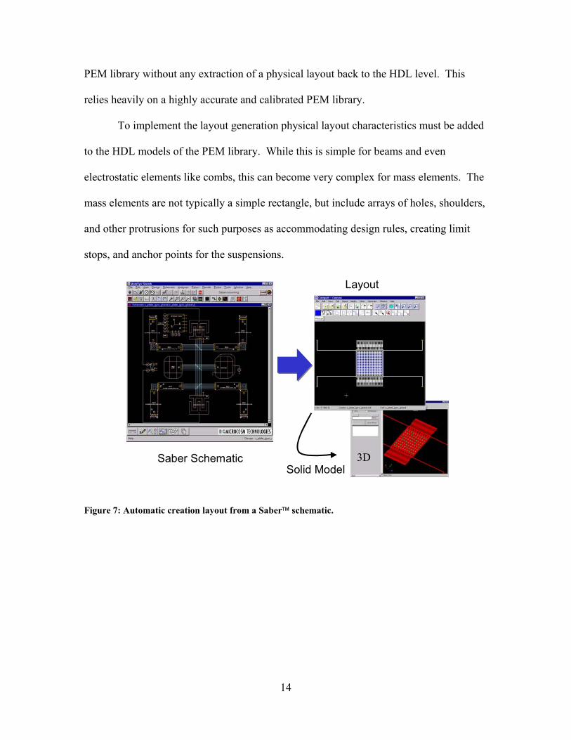
PEM library without any extraction of a physical layout back to the HDL level. This
relies heavily on a highly accurate and calibrated PEM library.
To implement the layout generation physical layout characteristics must be added
to the HDL models of the PEM library. While this is simple for beams and even
electrostatic elements like combs, this can become very complex for mass elements. The
mass elements are not typically a simple rectangle, but include arrays of holes, shoulders,
and other protrusions for such purposes as accommodating design rules, creating limit
stops, and anchor points for the suspensions.
Saber Schematic
Layout
3DSolid Model
Figure 7: Automatic creation layout from a Saber schematic.
15
1.2.3 Spice Based MEMS Cadtool Developments
1.2.3.1 Mechanical schematic (ADICE/SPICE based models)
At Analog Devices, prior to the MEMS CAD program, an experienced MEMS
designer must manually produce a simplified SPICE macromodel of the MEMS device,
which is then incorporated into the circuit model of the complete system. This procedure
is quite time consuming and can introduce significant errors. More importantly, the first-
order nature of the SPICE model, underpinned by the inaccuracies in the underlying
simulations, ensure a significant number of design-and-manufacturing iterations, which
results in sub-optimal performance, higher costs, and greater time-to-market. As the
complexity of the MEMS devices increase, this custom SPICE methodology has
unfortunately becoming increasingly intractable.
The alternative that was developed at Analog Devices was to create a mechanical
schematic representation of the MEMS device. In this representation the individual
components (e.g. mass, spring, damping, capacitor, limit stop, boundary condition) are
modeled in SPICE and are connected with wires that specify the mechanical and
electrical connectivity of the device. The resulting mechanical schematic looks exactly
like a circuit schematic except the wires represent force and position instead of current
and voltage. Figure 8 shows the mechanical schematic of the ADXL76. The mechanical
schematic is another top-down design flow, which is very similar to the PEM library
approach developed in MEMCAD, the difference being primarily the modeling
language.
In the mechanical schematic the degrees of freedom are strictly translation. The
implicit method is compatible to extending to rotational degrees of freedom, but the

16
SPICE syntax does not readily permit it. In conventional circuit simulators the through
variable is current, and the across variable is voltage. From the mathematics, it follows
that an analogous relationship can be made with the mechanical variables force and
displacement, force being the through variable and displacement being the across
variable. Note that other mappings are possible, but the aforementioned is in general the
most convenient to implement.
Springs
Mass
Damper
Limit StopsSense Caps Vertical
Parallel Plate
Force Caps
BoundaryCondition
Figure 8: ADXL76 mechanical schematic (2 DOF) implemented in Cadence using Spice models for each individual component.
In the standard electrical engineering definition positive current flow between two
nodes is defined as flowing from the higher to lower potential. In the case of the
mechanical analogy, we define the force (through variable) as follows: the force through
the element is the reaction force on the positively displaced node caused by the element.
By using this definition, elements such as negative resistors are avoided, and current
direction continues to behave as expected, i.e. it flows from a “high” potential to a “low”

17
potential. The easiest way to remember this convention is as follows: if the current is
positive, then the “high” node is being pulled towards the “low” node. Conversely, if the
current is negative, then the “high” node is being pushed away from the “low” node.
Circuit simulators are generally tuned to deal with units for volts and amps, which
are common in VLSI electronics. A direct mapping to the position and force for MEMS
can result in values of the fundamental solution variable, which are significantly out of
the range of what is normally expected by SPICE. To alleviate this problem, all
macromodels include scaling parameters for both position and current, which enable the
user to scale the fundamental solution variables. For the types of problems solved at
Analog Devices this scaling parameters are both about 10-6.
Nonlinear components were developed for the damping and the capacitor
elements. The initial damping and capacitor models were simple small signal models.
The damping model, for example, was simple viscous damping where the gap dimension
was not included. By including the gap in the model for damping (e.g. squeeze-film
damping is proportional to gap-3), the damping resulting from large motions of the mass
was modeled.
The large displacement accurate capacitor models also require a nonlinearity
which is given by the well know parallel plate capacitor equation.
)()(
xdAxC−
=ε (1)
In the original mechanical schematic 2DOF capacitor model the results from a group of
3D BEM simulations were curve fit to a polynomial. While this was readily
implemented in SPICE, it was not accurate for large displacements. A small current
feedback loop was used within the new capacitor model to implement the nonlinear

18
capacitance, which would be valid over very large deformations. A similar feedback
loop was used for the nonlinear force that is generated across the air gap capacitor.
Figure 9 shows the results of an overload acceleration of 2000g in the y-axis
applied to the ADXL76. Both the small-signal and large-signal model results are
displayed. The small-signal results show no indication of the mass hitting the limit stops
Small-signal Large-signal
Acce
l (g)
X D
isp
(um
)Z
Dis
p(u
m)
Figure 9: Response of mechanical schematic model of ADXL78 accelerometer to a 2000g overload. Demonstrates the implementation of nonlinear damping.
at about 1.2µm while the large-signal models show a large increase in the damping to the
extent to which the mass does not begin to spring back after the acceleration impulse has
ended. To be fair, hard limit stops were removed from the small signal model as they are
non-physical, but even with the limit stops present the small signal model would respond
immediately after the acceleration impulse ended. Note also the cross axis sensitivity that
19
is shown by the z-axis response. This arose from the 2 DOF model for the capacitance
that was obtained from 3D BEM simulations.
1.2.3.2 Verification of MEMS: DRC & LVS
A vital requirement in the efficient design and layout of an integrated MEMS
device is the verification that the layout of the device is indeed what was modeled and
simulated. In electronic CAD design rule checking (DRC) and layout versus schematic
(LVS) checks are applied to insure that the design doesn’t violate process design rules
and that the layout of the transistor/capacitor/resistor is of the appropriate size and
connectivity.
Implementation of a full mechanical equivalent of LVS proved to be beyond the
abilities of this project. However, several very useful tools were created in the Cadence
environment to facilitate the verification and checking of the MEMS device layout.
These tools; MemsXView, MemsCheck, and Memsdbx, were made available for
licensing from Microcosm, but to date they have not been including in any release of
MEMCAD or CoventorWare.
1.2.3.2.1 MemsXView
MemsXView provides the ability to map port connectivity between layout and
schematic. Part of the normal LVS flow is the extraction process. During extraction all
of the devices and all the connectivity between the devices are identified. Since we were
not able to extract the MEMS device directly we incorporated labels in the layout to
identify specific parts. The labels provided the connectivity. Unfortunately, while this
insured that things were connected correctly it was still subject to human error, as an
20
engineer must manually place the labels. Better would be to automatically extract the
MEMS device and thus all of the connectivity. MemsXView is the skill code front-end
to Memsdbx that allows graphical cross-probing to help quickly identify the errors.
1.2.3.2.2 Memsdbx
Memsdbx is the Dracula runset, which determines the connectivity of the MEMS
device. This runset can also be thought of as implementing ERC – electrical rules
checks. As mentioned above this method of manually placing labels is subject to human
error and thus not robust, but it is much better than what we had before, which was no
software verification.
1.2.3.2.3 MemsCheck
MemsCheck is collection of skill code to check the symmetry of the MEMS
device about difference axes. Specific layers could be selected and tested against the X
or Y-axes. MemsCheck also implemented a mass calculation as well as an area and
perimeter calculation for the complex shapes of MEMS devices. This was used to verify
that the mass used in the macromodel was indeed what was represented in the layout.
1.2.3.3 Modification of Autobem tool for Macromodeling
During the course of this project it was becoming increasingly clear that the
accurate simulation of overload operation of accelerometers and gyroscopes was critical.
The ability to model this type of input enables both improved designs as well as their
insertion into many new applications (e.g. smart munitions). In this application, the
initial acceleration is many times the full-scale resolution of the part. It is necessary to
know the performance of the part during and after the initial acceleration and that

21
acceleration measurements are accurate once the input acceleration is below full-scale.
Also, we need to accurately know how well the devices handle momentary, few times full
scale, over-range shocks while in operation. We have found that due to the desirably
small size and standard IC mounting of ADI devices we respond to mechanical shocks
naturally present in many systems that other more bulky devices tend to damp out due to
their size and other specialized mounting.
Towards these ends an alternate simulation engine was explored with a
subcontract with Coyote Systems. The subcontract added features to Coyote System's
software Autobem to make it a more useful macromodeling tool for real-world design.
Autobem has been found to be easy to use, accurate, and fast in simulating electrostatic
problems. Unlike other software packages available, this tool has both a batch language
as well as an adaptive-meshing routine that works very well. Autobem was used
extensively in the capacitance simulations of the ADXL190 and ADXL78. This was very
challenging as we were interested in the change in capacitance that is 1% at full-scale.
We required 1% accuracy on a 1% change in capacitance or 100ppm. Most electrostatic
simulators have serious problems achieving this level of accuracy because of the mesh
and time required. Autobem eliminated both of these issues. The recently released
ADXL78 accelerometers, which used Autobem extensively, have very tight sensitivity
distributions thus proving the success of the capacitive modeling.
Nevertheless, Autobem was not designed for macromodel extraction. The plan
was to make the necessary changes to the code to automate macromodeling. The primary
changes involve the modifications of the geometrical representation of the problem
within Coyote's data structures. This would allow Autobem to create macromodels that

22
incorporate the manufacturing variations of the structure (e.g., width, thickness, length).
Fortunately, the initial data structure was very compatible with this change. The BEM
mesh was already relative to the solid model geometry. All that was required was to add
a few changes so that the geometry could be easily deformed mathematically.
The geometry modification ability combined with the batch-language interface
with Autobem made creating macromodels much easier. Without these features, a user
was required to modify the layout, re-enter the data into Coyote software, and then re-use
the adaptive-meshing technique to achieve an optimal mesh. This takes additional time
and requires user input and is thus also subject to error. This process however cannot
model out-of-plane motion such curvature in the structural layer.
Figure 10 shows the application of the macromodeling on the curvature of the
ADXL76 accelerometer. As with MEMCAD the solid model is generated from a
Figure 10: Macromodeling using AutoBEM - warpage of ADXL76 accelerometer and resulting charge distribution.
File Edit Vie» ftvilid
^
$»
^BE3
ri«|t»!llli:sMi!ir:rti)TO.]: 4wi:. wnili- ?.KU Ulyli-s IN, |«v..n!j **»!?» I
I.VI-il'1'.r W'l' .■.irrm;-fVt-.-TT
Tilt Edit MM (r«!'«!!
"2ü_

23
physical layout and a process description file. The electrode names can be identified in
the layout program. This eliminates the need to “pick” all of the electrodes after the solid
model is created. Next, the boundary conditions are established and the simulation is
specified. Finally, the solver is launched with adaptive mesh refinement to a given
criteria such as the change in change on a given electrode changes less than a given
percent from the previous solution. When completed a number of parameters can be
displayed or extracted: electrostatic change and flux, force and torque in and about the
coordinate axes.
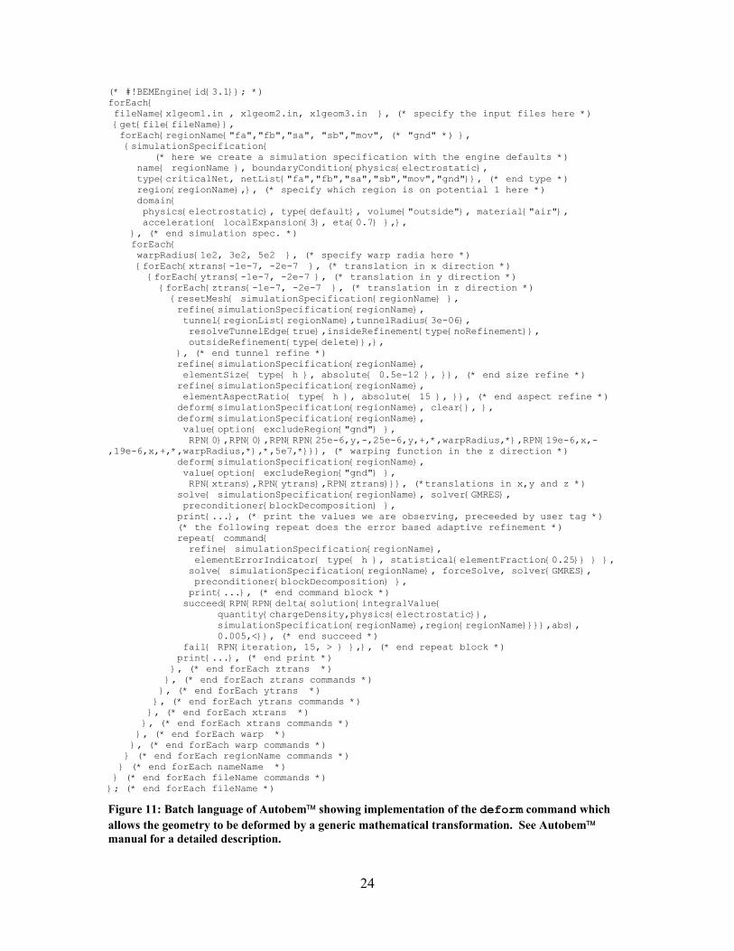
Figure 11 shows an example of a batch input file for the exaction of capacitance
over the space of transformations of the mass in x, y, and z as well as the curvature of the
mass. The central function is the deform command as well as the print command.
deform uses a function called rpn, which provides a confusing stack based
mathematics. Any standard mathematical transformation can be created with this
command including transcendental functions. The print command outputs the resulting
parameter (e.g. capacitance) to the log file. Unfortunately, there was no GUI interface
built around the output. The user is required to parse the log file and then curve fit the
results, which is typically performed in Matlab. However, this worked well in concert
with the capacitors in the mechanical schematic described in Section 1.2.3.1.
24
(* #!BEMEngine{id{3.1}}; *) forEach{ fileName{xlgeom1.in , xlgeom2.in, xlgeom3.in }, (* specify the input files here *) {get{file{fileName}}, forEach{regionName{"fa","fb","sa", "sb","mov", (* "gnd" *) }, {simulationSpecification{ (* here we create a simulation specification with the engine defaults *) name{ regionName }, boundaryCondition{physics{electrostatic}, type{criticalNet, netList{"fa","fb","sa","sb","mov","gnd"}}, (* end type *) region{regionName},}, (* specify which region is on potential 1 here *) domain{ physics{electrostatic}, type{default}, volume{"outside"}, material{"air"}, acceleration{ localExpansion{3}, eta{0.7} },}, }, (* end simulation spec. *) forEach{ warpRadius{1e2, 3e2, 5e2 }, (* specify warp radia here *) {forEach{xtrans{-1e-7, -2e-7 }, (* translation in x direction *) {forEach{ytrans{-1e-7, -2e-7 }, (* translation in y direction *) {forEach{ztrans{-1e-7, -2e-7 }, (* translation in z direction *) {resetMesh{ simulationSpecification{regionName} }, refine{simulationSpecification{regionName}, tunnel{regionList{regionName},tunnelRadius{3e-06}, resolveTunnelEdge{true},insideRefinement{type{noRefinement}}, outsideRefinement{type{delete}},}, }, (* end tunnel refine *) refine{simulationSpecification{regionName}, elementSize{ type{ h }, absolute{ 0.5e-12 }, }}, (* end size refine *) refine{simulationSpecification{regionName}, elementAspectRatio{ type{ h }, absolute{ 15 }, }}, (* end aspect refine *) deform{simulationSpecification{regionName}, clear{}, }, deform{simulationSpecification{regionName}, value{option{ excludeRegion{"gnd"} }, RPN{0},RPN{0},RPN{RPN{25e-6,y,-,25e-6,y,+,*,warpRadius,*},RPN{19e-6,x,-,19e-6,x,+,*,warpRadius,*},*,5e7,*}}}, (* warping function in the z direction *) deform{simulationSpecification{regionName}, value{option{ excludeRegion{"gnd"} }, RPN{xtrans},RPN{ytrans},RPN{ztrans}}}, (*translations in x,y and z *) solve{ simulationSpecification{regionName}, solver{GMRES}, preconditioner{blockDecomposition} }, print{...}, (* print the values we are observing, preceeded by user tag *) (* the following repeat does the error based adaptive refinement *) repeat{ command{ refine{ simulationSpecification{regionName}, elementErrorIndicator{ type{ h }, statistical{elementFraction{0.25}} } }, solve{ simulationSpecification{regionName}, forceSolve, solver{GMRES}, preconditioner{blockDecomposition} }, print{...}, (* end command block *) succeed{RPN{RPN{delta{solution{integralValue{ quantity{chargeDensity,physics{electrostatic}}, simulationSpecification{regionName},region{regionName}}}},abs}, 0.005,<}}, (* end succeed *) fail{ RPN{iteration, 15, > } },}, (* end repeat block *) print{...}, (* end print *) }, (* end forEach ztrans *) }, (* end forEach ztrans commands *) }, (* end forEach ytrans *) }, (* end forEach ytrans commands *) }, (* end forEach xtrans *) }, (* end forEach xtrans commands *) }, (* end forEach warp *) }, (* end forEach warp commands *) } (* end forEach regionName commands *) } (* end forEach nameName *) } (* end forEach fileName commands *) }; (* end forEach fileName *)
Figure 11: Batch language of Autobem showing implementation of the deform command which allows the geometry to be deformed by a generic mathematical transformation. See Autobem manual for a detailed description.
25
1.2.4 Application of New Tools in Real Designs
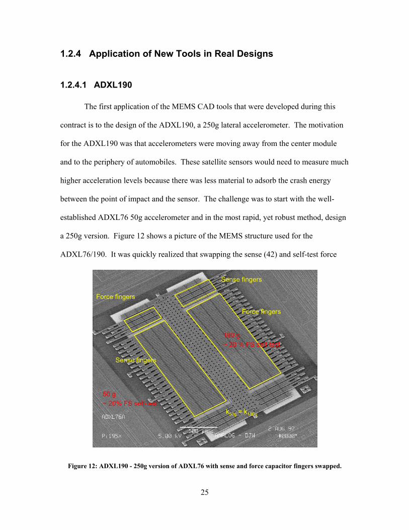
1.2.4.1 ADXL190
The first application of the MEMS CAD tools that were developed during this
contract is to the design of the ADXL190, a 250g lateral accelerometer. The motivation
for the ADXL190 was that accelerometers were moving away from the center module
and to the periphery of automobiles. These satellite sensors would need to measure much
higher acceleration levels because there was less material to adsorb the crash energy
between the point of impact and the sensor. The challenge was to start with the well-
established ADXL76 50g accelerometer and in the most rapid, yet robust method, design
a 250g version. Figure 12 shows a picture of the MEMS structure used for the
ADXL76/190. It was quickly realized that swapping the sense (42) and self-test force
Sense fingers
Force fingers
Sense fingers
Force fingers
50 g~ 20% FS self-test
190 g~ 20 % FS self-test
k50g = k190g
Figure 12: ADXL190 - 250g version of ADXL76 with sense and force capacitor fingers swapped.
26
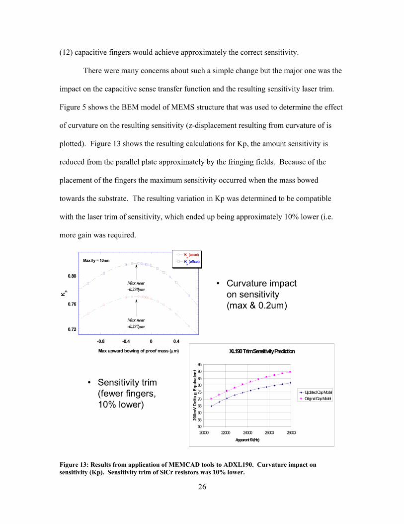
(12) capacitive fingers would achieve approximately the correct sensitivity.
There were many concerns about such a simple change but the major one was the
impact on the capacitive sense transfer function and the resulting sensitivity laser trim.
Figure 5 shows the BEM model of MEMS structure that was used to determine the effect
of curvature on the resulting sensitivity (z-displacement resulting from curvature of is
plotted). Figure 13 shows the resulting calculations for Kp, the amount sensitivity is
reduced from the parallel plate approximately by the fringing fields. Because of the
placement of the fingers the maximum sensitivity occurred when the mass bowed
towards the substrate. The resulting variation in Kp was determined to be compatible
with the laser trim of sensitivity, which ended up being approximately 10% lower (i.e.
more gain was required.
XL190 Trim Sensitivity Prediction
50556065707580859095
20000 22000 24000 26000 28000
Apparent f0 (Hz)
200m
V D
elta
g E
quiv
alen
t
Updated Cap ModelOriginal Cap Model
• Curvature impact on sensitivity (max & 0.2um)
0.36
0.38
0.4
-0.8 -0.4 0 0.4
Kp (accel)
Kp (offset)
Kp
Max upward bowing of proof mass (µm)
Max near-0.237µm
Max near-0.230µm
Max δy = 10nm
0.80
0.76
0.72
• Sensitivity trim (fewer fingers, 10% lower)
Figure 13: Results from application of MEMCAD tools to ADXL190. Curvature impact on sensitivity (Kp). Sensitivity trim of SiCr resistors was 10% lower.
27
1.2.4.2 ADXL78
The ADXL78 is the 4th generation 50g lateral accelerometer at Analog Devices.
The primary considerations were in reducing the cost (i.e. the size) of the part as well as
producing a sensor that was more robust to overload conditions. The final embodiment
of the sensor was actually two single-axis lateral accelerometers that are measured
differentially. The area of the two sensors is about 70% of the ADXL76 sensor and the
overall chip area was reduced by half.
Autobem and the mechanical schematic were used extensively in the development
of the MEMS structure. The impact of these tools can be seen by the fact that the
sensitivity as measured on actual devices was within a few percent of the designed and
simulated value. This product because of the much higher overload specifications
motivated the modifications to the mechanical schematic, incorporation of nonlinear
capacitance and damping.
1.2.4.3 SPCMems – Modeling Process Corners
A preliminary evaluation of the SPCMems methodology was performed. That
methodology varied the solid model geometry based on understood process variations
and then created AutoMM models for each of these geometries. In this way, models
that spanned the process variation space were developed to yield simulation results
spanning the space. However, given the large number of FEM/BEM simulations required
for each of these AutoMM models, this methodology proved difficult to use. The
advent of the PEM models allowed a much more computationally efficient way to
perform the same exploration of the process variation space. Figure 14 thru Figure 16
28
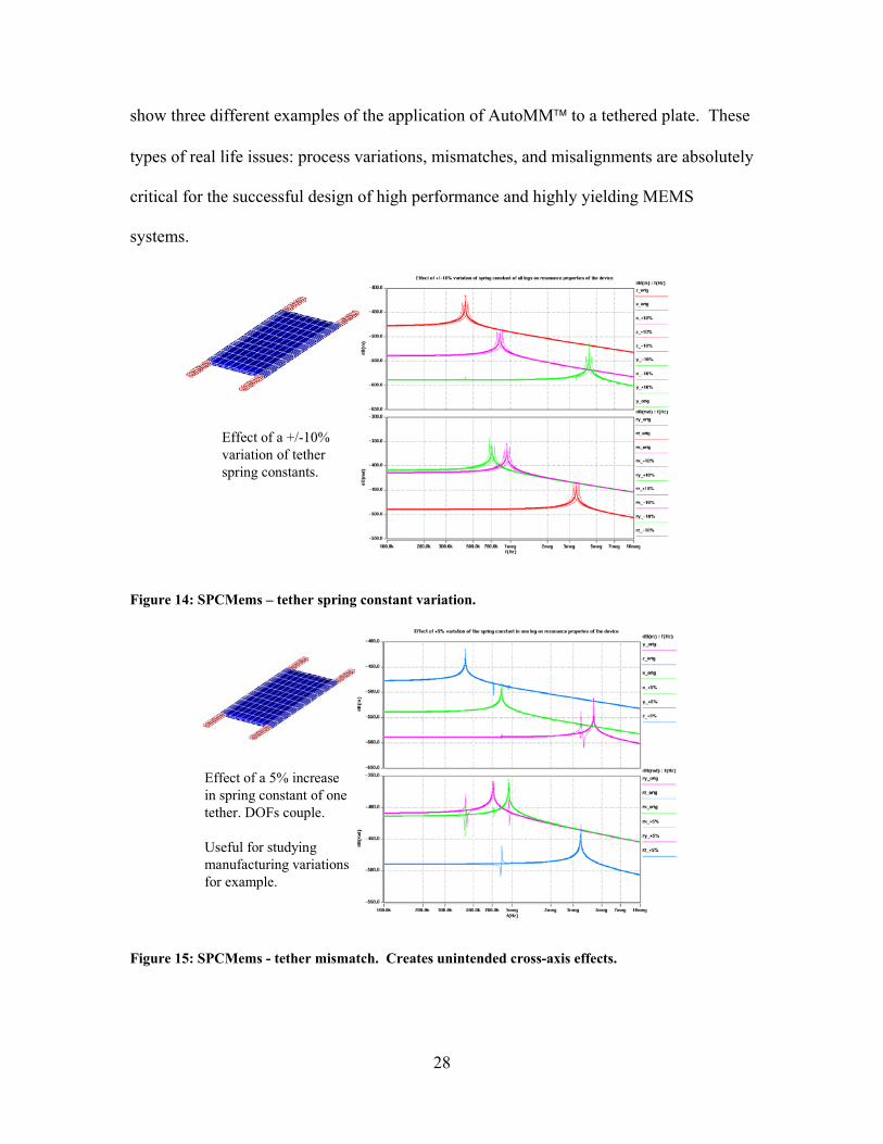
show three different examples of the application of AutoMM to a tethered plate. These
types of real life issues: process variations, mismatches, and misalignments are absolutely
critical for the successful design of high performance and highly yielding MEMS
systems.
Effect of a +/-10% variation of tether spring constants.
Figure 14: SPCMems – tether spring constant variation.
Effect of a 5% increase in spring constant of one tether. DOFs couple.
Useful for studying manufacturing variations for example.
Figure 15: SPCMems - tether mismatch. Creates unintended cross-axis effects.
MB *»f*) .(*,)
- -* ll
\ A mum
r. .Iff-,
—~—.
<?.•••*
-4 K. Man
■.-«1
in

29
Effect of 10% misalignment of position of one tether.
Useful for packaging studies for example
Figure 16: SPCMems - misalignment of tether anchor. Very useful for exploring packaging effects.
1.2.5 Uniform Design Environment for Integrated MEMS
Towards the end of the program Coventor and Analog Devices realized that while
the software, which had resulted from this program, did meet the program’s objectives it
could be greatly enhanced by porting it to a design environment that was more
compatible with circuit simulation. This would allow both the reduced order models of
MEMS devices and the integrated electronics to be simulated inside of a more widely
used circuit simulator. The choice of environment was Cadence using the SpectreRF
simulation tool, which is based on Verilog-A. While Saber can simulate circuits it was
originally developed as a system level tool. This legacy, and the resulting public image,
has prevented Saber from being utilized widely by the industry. Cadence is clearly the
dominant EDA tool on the market today and was thus the obvious choice. It should be
pointed out that the Cadence/SpectreRF interface with the AutoMM and PEM models
has continued beyond the end of the original contract and is now subject to an agreement
M « Wq (MM« «-«• O- C-W tf (-*«) * ■
■u .A. ■ -9
^^-^^^ . ID".
7 IB".
_, —■^-~»_ 1 —"-^A---—
-Wl «■a
—m
1
i- ^H Ml
^~~

30
between Analog Devices and Coventor. Nevertheless, the results which have been
achieved to the date of this final report are included as they are directly related to the
initial object of this program – development of an integrated MEMS design environment.
In the Cadence/SpectreRF implementation the engineer would have both Cadence
and CoventorWare running. The links between Cadence and CoventorWare, such as
layout to schematic conversion (AutoMM) and schematic to layout generation, are
created with Cadence skill code as well as interface code in CoventorWare. The two
major pieces of work were around he port of the AutoMM and PEM libraries from
MAST to Verilog-A and the implementation of a Cadence interface to these models.
Figure 17: Example of a gyro using MEMCAD models applied in a Cadence design environment. The properties of the electrode element are shown on the right.

31
Both MAST and Verilog-A are HDL languages so conversion was relatively
straightforward. This harder problem was interfacing with Cadence. This was primarily
through the parameters window for a given object (e.g. beam or plate in PEM library).
Incorporating the parameters in an efficient and user-friendly way was the problem.
Figure 17 and Figure 18 show two examples of the Cadence implementation of
the PEM library. The parameter window of an electrode and beam element are also
shown to demonstrate the complexity of this implementation. Figure 19 shows an
Figure 18: ADXL76 implemented using PEM library parameters in the Cadence environment. The properties of the 1 segment beam element are shown on the right.
example of the SpectreRF interface to a gyroscope. The simulation that is shown is an
AC analysis. This embodiment of the Cadence/CoventorWare interface requires the
use of at least Cadence version 4.4.6 and CoventorWare 2001.3.

32
Figure 19: Example of SpectreRF interface to macromodels in Cadence design environment - Gyroscope.
A validation report has been developed to demonstrate the accuracy of the PEM
and AutoMM models in the Cadence/SpectreRF design environment through detailed
comparison with ArchitectTM simulations (Saber environment), simulation data (3D
FEM/BEM) and experimental data. The purpose was to present the correlation between
the models and actual experimental data and/or 3D simulation result, on a handful of
carefully chosen cases defined in the validation plan in order to provide confidence for
Coventor and Analog Devices that PEM and AutoMM models are a viable design

33
methodology that will greatly shorten time-to-market and greatly increase the change of
first silicon success in the product development process.
The objectives of the validation plan were to evaluate the design environment,
simulation speed and performance. In order to meet the objectives outlined, four
validation tasks were identified (Table 1). Comparisons between the PEM and
AutoMM models and the measured data set will be conducted. Although the final
version of the validation report is as of yet not available it has already demonstrated that
most of the AutoMM and PEM models agree with the Saber simulation results as well
as FEM/BEM simulations. The test structures which were designed are currently being
fabricated. The final validation report should be available in Summer 2002. The reader
is encouraged to speak with Coventor then as this report contains a wealth of information
about the validity of the macromodels as well as the regions of appropriate applications
of the models (i.e. where the implicit approximations are valid).
Table 1: Validation criteria.
Name Structures Description Variation
Cantilever Beam FF Beam-center loaded
FF Beam-uniform loaded with axial
VP1 Elemental Devices-Mechanical
Comparison of mechanical response of some PEM library components with FEM simulations
FF Beam-uniform loaded with axial
Parallel Plate
Longitudinal Comb
VP2 Elemental Devices-Electrostatic
Comparison of mechanical response of some PEM library components with FEM simulations
Lateral Comb
Torsion Mirror
Gimbal Mirror (2-axis)
XL76
VP3 Test Devices Comparison of electromechanical response of some PEM library components with 3D FEM/BEM coupled simulations
P20
34
Cantilever Beam
FF-Beam
Torsion Mirror
Comb Resonator
Xl76
VP4 Test Devices-Measured Data
Comparison of PEM library components with measured data
P20
1.3 Summary
The MEMSCAD DARPA program was very successful from the perspective of
all parties involved. Several new MEMS CAD tools were developed and released to the
MEMS design community via MEMCAD 4.0 and eventually CoventorWare as well
as AutoBEM. The primary development was AutoMM which established the first
automatic reduced order model extraction tool. To enable AutoMM the BEM
capacitance solver needed to be enhanced to solve real-world problems like
accelerometers and gyroscopes. Eventually this led to the development of the
parameterized electromechanical library (PEM library) as well as the schematic to layout
generator in MEMCAD.
Analog Devices also greatly improved the macromodeling capabilities in SPICE
through the development of the mechanical schematic (Cadence) and the enhancement of
AutoBEM to extract macromodels of complex MEMS capacitors. The verification of the
MEMS was improved through the development of MemsXView, MemsCheck and
Memsdbx, but the goal of a full mechanical LVS system was not achieved.
The newly developed MEMS CAD tools were applied to the ADXL190 and
ADXL78 and contributed significantly to their success. The MEMS CAD tools were
35
verified by comparing the simulations with measured results from test structures that
were designed during the course of this project. Both the PEM library and AutoMM
demonstrated the impacts on MEMS of process variations devices. This allows the user
to determine which parameters are most sensitive and to both focus process engineering
to improve critical steps as well as instruct the MEMS design on which parameters to
design around.
Finally, the project came full circle and by porting the PEM and AutoMM
models to Verilog-A models and by building a Cadence interface to the models a uniform
design environment for integrated MEMS was developed. This last project is now
subject to a separate contract between Coventor and Analog Devices and will be
completed this summer. When complete this uniform design environment will be made
available to the public through a new release of CoventorWare.
For a more detailed description of the software tools that were developed the
reader is directed to contact Coventor directly (www.coventor.com). The manuals for
CoventorWare are very detailed and contain many examples of MEMS components
like gyros, accelerometers and torsional mirrors. DC, AC and transient coupled
simulations are fully documented to help reduce the learning time.
1.4 Publications
The following are a list of the publications directly resulting from the work on this
program. There are many other publications, which have used the code developed during
this program, but they will not be listed here.
1. N.R. Swart, S.F. Bart, M.H. Zaman, M. Mariappan, J.R. Gilbert, and D. Murphy,
“AutoMM: Automatic Generation of Dynamic Macromodels for MEMS

36
Devices,” in Proceedings of the IEEE Eleventh Annual International Workshop
on Micro Electro Mechanical Systems, Heidelberg, Germany, Jan. 25-29, 1998,
pp. 178--183.
2. Zaman, M.H., S.F. Bart, V.L. Rabinovich, C.K. Ghaddar, I. Tchertkov, and J.R.
Gilbert, “A Technique for Extraction of Macro-Models in System Level
Simulation of Inertial Electro-Mechanical Micro-Systems”, in Technical
Proceedings of the Second International Conference on Modeling and Simulation
of Microsystems, San Juan, Puerto Rico, April 19-21, 1999, pp. 163-167.
3. Zaman, M.H., S.F. Bart, J.R. Gilbert, N.R. Swart, M. Mariappan, “An
Environment for Design and Modeling of Electro-Mechanical Micro-Systems”,
Journal of Modeling and Simulation of Microsystems, 1, 1999, pp. 65-76.
4. Bart, S.F., N.R. Swart, M. Mariappan, M.H. Zaman, and J.R. Gilbert, “An
Environment for MEMS Design and Varification”, in Technical Proceedings of
the 1998 International Conference on Modeling and Simulation of Microsystems
Semiconductors, Sensors and Actuators, Santa Clara, CA, April 6-8, 1998, pp.
386-391.
5. Romanowicz, B.F., M.H. Zaman, S.F. Bart, V.L. Rabinovich, I. Tchertkov, S.
Zhang, M.G. da Silva, M. Deshpande, K. Greiner, J.R. Gilbert, S. Cunningham,
“A Methodology and Associated CAD Tools for Support of Concurrent Design of
MEMS”, Journal of Computer Modeling in Engineering and Sciences, vol. 1,
2000, pp. 45-63. (Invited)
2 Business/Financial Aspects of the Agreement
2.1 Total Costs Incurred
ADI signed up for a cost share of $723,004, or 24.55% of a total estimated cost of
$2,945,382. By the summer of 2001, we were a bit underspent on our cost share but have
now caught up—actually exceeded the $723,004 contractually obligated amount.

37
In February 2002, DCAA sent one of their auditors (Simon W. Leung) to Analog
Devices to audit the incurred cost of the MEMS CAD program. Simon reviewed our
cost-collection system, backup documentation, management controls, and sample tested a
random selection of invoice data. We believe that he was satisfied that everything was in
order, although we haven’t seen his audit report.
Simon was shown a draft copy of Public Voucher no. 35 (zero dollar invoice),
whereby Analog Devices documented that its cost share had been met. Since this was a
draft and it was for zero dollars, Simon did not include draft voucher 35 in his audit.
Nevertheless, voucher 35 has since been submitted to DCAA Boston in the required
manner.
At the final tally, ADI had spent $844,268.21, or 27.51% of the final actual total
cost of $3,069,101.11. The Government share at the final tally was $2,033,253.00 or
exactly equal to the contractual amount. Microcosm Technologies, Inc. (now called
Coventor, Inc.) also exceeded their contractual amount of $189,125 by spending
$191,579.90.

38
2.1.1 Estimated Cost per Contract
Total Estimated Cost of Project $2,945,382.00
DARPA Share of Estimated Cost $2,033,253.00
ADI Share of Estimated Cost $723,004.00
MTI Share of Estimated Cost $189,125.00
2.1.2 Final Actual Costs per Vouchers
Cost Element Cumulative Hours/Costs
Analog Devices Hours 9,593.00
Unburdened Labor 330,511.77
Masks 0.00
Wafer Fabrication 0.00
Consultant Fees 6,274.13
Computer Software License & Maintenance Fee 345,550.00
Reverse: costs (labor) in excess of allocation -
TOTAL ADI DIRECT COSTS 682,335.89
INDIRECT COSTS
Engineering Overhead 200.0% 619,199.14
G and A 35.0% 548,205.29
TOTAL ADI INDIRECT COSTS 1,167,404.43
TOTAL ADI PROJECT COSTS 1,849,740.32
DARPA share of Allowed ADI Expenditures 0.00% 1,005,472.12
ADI Share of Allowed ADI Expenditures 100.00% 844,268.21
Microcosm Technologies, Inc.
TOTAL MTI PROJECT COSTS 1,219,360.79
DARPA share of Allowed MTI Expenditures 1,027,780.89
MTI Share of Allowed MTI Expenditures 191,579.90
Cost Share Distribution (% of Cum.)
DARPA, INVOICED 66.25% 2,033,253.00
Analog Devices, Inc. 27.51% 844,268.21
Microcosm Technologies, Inc. 6.24% 191,579.90
TOTAL EXPENDITURES 100.00% 3,069,101.11