computer aided design standards - king county
TRANSCRIPT

Computer Aided Design Standards
Version 2.5.13 – June 2019
Find this document at https://www.kingcounty.gov/depts/transportation/metro/about/design‐construction‐standards.aspx, CAD Manual
Metro Transit Department, Capital Division Capital Project Delivery, Engineering (formerly Design & Construction)
King County Metro Transit, Capital Project Delivery, Engineering
Computer Aided Design Guidelines 1 June 2019 Release http://www.kingcounty.gov/depts/transportation/metro/design‐construction‐standards.aspx, CAD Manual
Computer Aided Design Guidelines
Contents
....................................................................................................................................................................................................................................... 1
Introduction ................................................................................................................................................................................................................... 2
Drawing Media ............................................................................................................................................................................................................... 2
Drawing Package Organization ...................................................................................................................................................................................... 2
Drawing Numbering and File Naming ............................................................................................................................................................................ 4
Title Blocks ..................................................................................................................................................................................................................... 5
Abbreviations ................................................................................................................................................................................................................. 6
Text and Font Styles ....................................................................................................................................................................................................... 6
Mtext Placement ............................................................................................................................................................................................................ 2
Reference Symbols ......................................................................................................................................................................................................... 8
Layer Naming Convention ............................................................................................................................................................................................ 11
Standard Layer Names ................................................................................................................................................................................................. 13
Substation Site Codes .................................................................................................................................................................................................. 24
Pen Settings/Plotter Configuration .............................................................................................................................................................................. 26
Drawing Stamping Procedures ..................................................................................................................................................................................... 27
Drawing Submittals ...................................................................................................................................................................................................... 27
CAD Deliverables .......................................................................................................................................................................................................... 28
Revision History ........................................................................................................................................................................................................... 30

King County Metro Transit, Capital Project Delivery, Engineering
Computer Aided Design Guidelines 2 June 2019 Release http://www.kingcounty.gov/depts/transportation/metro/design‐construction‐standards.aspx, CAD Manual
Introduction These Standards are for use in all CAD projects for the Capital Division of King County Metro Transit Department.
The purpose of these Standards is to provide a consistent manner in which CAD project drawings are created, published, maintained, and made accessible for future reference.
Within the enclosed Standards for electronic drafting files, some exceptions apply:
Layer names listed in this document are set forth as a base guideline, with further definition in the standard format welcomed as required.
The General blocks are for general use.
Drawing Media The minimum Computer Aided Design program used by the Division at this time is AutoCAD 2017, saving as 2013 or better.
PDF’s are acceptable as final as‐built drawing deliverables from consultants, contractors and vendors only when CAD files were not the source of the original, as in field sketches. CAD files and corresponding PDF’s with correct CAD display are requested. PDF page size shall all be the same throughout the file.
Use standard A (8.5"x11"), ANSI B (11"x17") or ANSI D (22"x34") drawing sheets sizes as project requirements dictate.
Requirements for number of paper copy deliverables or pdf deliverables vary with project requirements. Timing, contents and format shall be determined by the Project Manager and the Project Engineer, in coordination with the requirements of Milestone Reviews, Permit Submittals, Bid Documents Deliverables, Contract Implementation and other requirements as applicable.
Drawing Package Organization The following list serves as an outline and shall be conformed to the contents of the project.
Discipline Code
G ‐ General Drawing cover, drawing index, etc.
TEC ‐ Temporary Erosion & Sedimentation Control Temporary measures for erosion and sedimentation control.

King County Metro Transit, Capital Project Delivery, Engineering
Computer Aided Design Guidelines 3 June 2019 Release http://www.kingcounty.gov/depts/transportation/metro/design‐construction‐standards.aspx, CAD Manual
C ‐ Civil Grading, paving, utilities, exterior site improvements, etc.
L ‐ Landscape Landscaping & irrigation.
A ‐ Architecture Building construction, building envelope systems, interior and exterior finishes.
S ‐ Structural Building structure and systems.
M ‐ Mechanical HVAC, piping, plumbing, equipment, etc.
FP – Fire Protection Fire protection systems.
E ‐ Electrical Power, lighting, security systems.
T ‐ Trolley Trolley overhead systems.
TC – Traffic Control Traffic control plans.
TS – Traffic Signal Signalization and wiring.
U – Urban Design Urban planning.
Sheet Designator
0 General (general symbols, legends, notes, etc.) 1 Plans (horizontal views)
2 Elevations (vertical views)
3 Sections (sectional views)

King County Metro Transit, Capital Project Delivery, Engineering
Computer Aided Design Guidelines 4 June 2019 Release http://www.kingcounty.gov/depts/transportation/metro/design‐construction‐standards.aspx, CAD Manual
4 Enlarged Plans (partial plans)
5 Details
6 Schedules and Diagrams (P & ID’s etc.) 7 User Defined
8 User Defined
9 3D views (isometrics, perspectives, photos)
Drawing Numbering and File Naming For Area Location field, use 1 and higher number when a project involves more than one building or site location. No Area Location number is required when there is only one work location.
7
1 A1.01
DisiplineDesignator
Area Location
SequentialDrawingNumber
Space
A1.01
DisiplineDesignator
SequentialDrawingNumber
Space
Multiple Facility Locations in Contract One Facility Location in Contract
The Drawing file name shall include the drawing number or series of numbers, and a recognizable and consistent abbreviation of the project name.
For example:
SODO CS 1_G0.01‐G1.03.dwg
Exceptions to this standard may include Civil Drawing series, where each type of Civil activity way have a two‐digit designator. as in C10.XX series ‐ Grading C20.XX series ‐ Paving C30.XX series ‐ Drainage

King County Metro Transit, Capital Project Delivery, Engineering
Computer Aided Design Guidelines 5 June 2019 Release http://www.kingcounty.gov/depts/transportation/metro/design‐construction‐standards.aspx, CAD Manual
Title Blocks Title Block Border and File Organization
Two alternatives are acceptable:
1. The preferred method is external referencing of KCBORD.dwg into all the drawings. At a maximum, provide one border drawing per each discipline.
2. One border set per drawing, one drawing per file.
In this method, all title blocks are to be inserted in Layout/Paper Space at a scale of 1:1.
Each D‐size title block/border drawing file contains four separate attributed blocks: (do not explode these, use the ATTEDIT command to fill in fields.
Title block/border drawing parts are contained in START‐KCTDC‐ALL‐DISCIPLINES.zip at http://bitly.com/DCCADStandards.
1. KCTDC‐Border.dwg:
The border line work and stationary project information are typically used as external reference.
2. Shtinfod.dwg:
Drawing sheet content filled out per sheet.
3. DREV.dwg:
Milestone deliverables are indicated in the revision block. This block identifies Drawing deliverables to communicate to the end user what status it represents. Revisions should be numerical and begin with 1. Each of the following bulleted items represents a conditional series of potential revisions within the Drawing’s lifetime:
a. Design Phase:
Internal review milestones in bold as shown in the schematic below, at lower left.
External release documentation, such as permitting submittals and corrections.
Drawing revisions provided during the procurement process as Addenda.
b. Implementation Phase:
Drawing revisions provided during implementation as RFI responses or Work Change Orders.
As‐Built Drawings completed from construction mark‐ups and records.

King County Metro Transit, Capital Project Delivery, Engineering
Computer Aided Design Guidelines 6 June 2019 Release http://www.kingcounty.gov/depts/transportation/metro/design‐construction‐standards.aspx, CAD Manual
4. XERD.dwg:
This is a remote text block that retrieves filename, drawing layout, file location, user, date, time, and external references. Residing once on an externally referenced, stationary project border, it will provide layout and drawing‐specific information.
The following schematic shows the parts of a complete project border set, and how to complete it. Typical Title Block Labeling Configuration
KCTDC‐Border.dwg
Abbreviations
All abbreviations used in a project plan set shall be identified in general or discipline‐specific abbreviations lists.
Do not use ‘boiler plate’ lists without conforming them to the Drawing Package.
Do not include abbreviations not used, or cross‐discipline duplicates.
Excessive use of abbreviations is discouraged.
Use punctuation only where the abbreviation forms a word.
Text and Font Styles Text heights and styles shall conform to the following (at full‐size):
SHTINFOD.dwg XERD.dwg DREV.dwg

King County Metro Transit, Capital Project Delivery, Engineering
Computer Aided Design Guidelines 2 June 2019 Release http://www.kingcounty.gov/depts/transportation/metro/design‐construction‐standards.aspx, CAD Manual
Arial or Arial Narrow: All drawing notation and dimension text
Height = 1/8”
Arial or Arial Narrow: Subtitles and Labels
Height = 3/16”
Arial Black: Cover Sheets
Height = ½”
For general use, do not modify text width factors to less than 1.0”, use Arial Narrow font for standardized narrow text.
Mtext Placement Annotations can be placed in paper space or model space.
Paper space placement is typically for project directives.
Model space placement is typically for labeling of permanent items that must be identified for the Record.
Annotations with leaders should have flush left multi‐line text.
When to the right of the subject, the leader should lead from the top left line of the mtext.
When to the left of the subject, the leader should lead from the lower right line of the mtext or smart leader.
Model space‐located text is typically limited to existing conditions of record. Project‐specific Construction Document text is typically placed in paper space.
For information and reference only, the following chart shows the size of text when located in model space to be shown in view‐specific scales.

King County Metro Transit, Capital Project Delivery, Engineering
Computer Aided Design Guidelines 7 June 2019 Release http://www.kingcounty.gov/depts/transportation/metro/design‐construction‐standards.aspx, CAD Manual
Text Height and Dimscale Chart
Dwg Scale Text Height Dimscale1/8" 3/16" 1/4"
0.125 0.1875 0.251:100 12.5 18.75 25 1001:60 7.5 11.25 15 601:50 6.25 9.375 12.5 501:40 5 7.5 10 401:30 3.75 5.625 7.5 301:20 2.5 3.75 5 201:10 1.25 1.875 2.5 101:5 0.625 0.9375 1.25 51:4 0.5 0.75 1 41:2 0.25 0.375 0.5 21:1 0.125 0.1875 0.25 12:1 0.0625 0.09375 0.125 0.54:1 0.03125 0.046875 0.0625 0.255:1 0.025 0.0375 0.05 0.210:1 0.0125 0.01875 0.025 0.1
1"=100'-0" 150 225 300 12001"=60'-0" 90 135 180 7201"=50'-0" 75 112.5 150 6001"=40'-0" 60 90 120 4801"=30'-0" 45 67.5 90 3601"=20'-0" 30 45 60 2401"=10'-0" 15 22.5 30 120
1"=1" 0.125 0.1875 0.25 13"=1'-0" 0.5 0.75 1 4
1 1/2"=1'-0" 1 1.5 2 81"=1'-0" 1.5 2.25 3 12
3/4"=1'-0" 2 3 4 161/2"=1'-0" 3 4.5 6 243/8"=1'-0" 4 6 8 321/4"=1'-0" 6 9 12 483/16"=1'-0" 8 12 16 641/8"=1'-0" 12 18 24 963/32"=1'-0" 16 24 32 1281/16"=1'-0" 24 36 48 1921/32"=1'-0" 48 72 96 384
King County Metro Transit, Capital Project Delivery, Engineering
Computer Aided Design Guidelines 8 June 2019 Release http://www.kingcounty.gov/depts/transportation/metro/design‐construction‐standards.aspx, CAD Manual
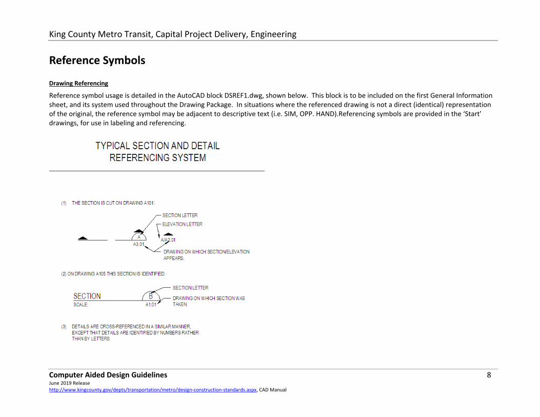
Reference Symbols
Drawing Referencing
Reference symbol usage is detailed in the AutoCAD block DSREF1.dwg, shown below. This block is to be included on the first General Information sheet, and its system used throughout the Drawing Package. In situations where the referenced drawing is not a direct (identical) representation of the original, the reference symbol may be adjacent to descriptive text (i.e. SIM, OPP. HAND).Referencing symbols are provided in the ‘Start’ drawings, for use in labeling and referencing.
King County Metro Transit, Capital Project Delivery, Engineering
Computer Aided Design Guidelines 9 June 2019 Release http://www.kingcounty.gov/depts/transportation/metro/design‐construction‐standards.aspx, CAD Manual
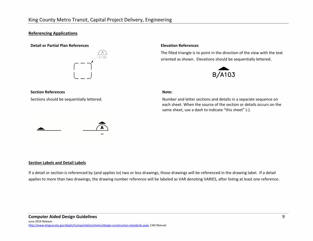
Referencing Applications
Detail or Partial Plan References
Elevation References
The filled triangle is to point in the direction of the view with the text oriented as shown. Elevations should be sequentially lettered.
Section References
Sections should be sequentially lettered.
Note:
Number and letter sections and details in a separate sequence on each sheet. When the source of the section or details occurs on the same sheet, use a dash to indicate “this sheet” (‐).
Section Labels and Detail Labels
If a detail or section is referenced by (and applies to) two or less drawings, those drawings will be referenced in the drawing label. If a detail applies to more than two drawings, the drawing number reference will be labeled as VAR denoting VARIES, after listing at least one reference.

King County Metro Transit, Capital Project Delivery, Engineering
Computer Aided Design Guidelines 10 June 2019 Release http://www.kingcounty.gov/depts/transportation/metro/design‐construction‐standards.aspx, CAD Manual
Label for Sections, Details or Partial Plans For use with one or two references.
North Arrows North arrows are to be placed in the upper left‐hand corner of the plan whenever possible. Plan north should be towards the top or to the left side of the drawing.
Source Plan Label This label identifies a plan that is not cut from anywhere else in the Drawing set.
Key Plans May be identified with a Source Plan label. Use Key Plans to show where a Partial Plan is within a Plan that is divided into a grid of Partial Plans.

King County Metro Transit, Capital Project Delivery, Engineering
Computer Aided Design Guidelines 11 June 2019 Release http://www.kingcounty.gov/depts/transportation/metro/design‐construction‐standards.aspx, CAD Manual
Bar Scales
Bar scales are required.
The ‘Start Drawing’ contains a block or the parts thereof named ‘scale.dwg’.
This is a scale bar with associative dimensions in the ‘scale bar’ dimension style. This can be customized to the scale of viewports by using the CHSPACE command, and updating the scale bar dimension style. The scale bar dimension style can be used with Civil or Architectural units.
Fixed scale bar blocks are available on request.
Layer Naming Convention Layers use the following convention:
PLAN LEVEL ‐ DISCIPLINE LAYER
STATUS ‐ LAYER DESCRIPTION SUPPLEMENTARY INFORMATION
Examples:
Building Plans:
PLAN LEVEL
DISCIPLINE LAYER STATUS
LAYER DESCRIPTION SUPPLEMENTARY INFORMATION
L1 ‐ M X ‐ PIP TXT
L1‐MX‐PIPTXT = Level‐one mechanical existing piping text.

King County Metro Transit, Capital Project Delivery, Engineering
Computer Aided Design Guidelines 12 June 2019 Release http://www.kingcounty.gov/depts/transportation/metro/design‐construction‐standards.aspx, CAD Manual
Civil & Trolley Plans
DISCIPLINE
LAYER*
STATUS
LAYER DESCRIPTION
SUPPLEMENTARY INFORMATION
C x ‐ stm line
CX‐STMLINE = Existing civil storm water system line
Plan Level:
RL ‐ Roof Plan (birds’ eye view to roof level)
L2 ‐ Level 2 (below roof to next level or floor)
L1 ‐ Level 1 (below 2nd floor or mezzanine ceiling to floor)
L0 ‐ Foundation Plan (below 1st floor slab)
(For buildings with three or more levels, use L and the level number.)
Discipline:
G = General, including functional
C = Civil
A = Architectural
S = Structural
M = Mechanical
E = Electrical
T = Trolley
Layer Status:
(*) placeholder
Status
Definition
Plotting Line Weight
(Extra fine, fine, medium, heavy and bold)
X Existing Extra fine or screened
D Demolition Heavy dashed line at perimeter; hatched field or ‘X’ over item.
R Relocated Bold
N New Bold
T Temporary Bold
Layer Description:
By naming. See Standard Layer Names, below.

King County Metro Transit, Capital Project Delivery, Engineering
Computer Aided Design Guidelines 13 June 2019 Release https://www.kingcounty.gov/depts/transportation/metro/about/design‐construction‐standards.aspx, CAD Manual
Layer Supplementary Information
CND Conduit
EQP Equipment
HAT Hatching
LINE Plan line
RET Return
SUP Supply
SYM Plan symbol
TXT Associated text
PLU Plumbing
*** Additional description as required
Standard Layer Names XX = Designates placeholder for Plan Level field (L0, L1, L2, RL or as required)
Section, Elevation, Detail and Line Schematic layers do not use XX designation.
General Layers
Gn‐TXT Annotations, labels, legends & notes on General drawings
0 Drawing frames or other non‐specific line work
vp Viewports. Set to non‐printing layer status.
0 Title block.
0 Title block attribute text.
0 Title block attribute text.

King County Metro Transit, Capital Project Delivery, Engineering
Computer Aided Design Guidelines 14 June 2019 Release https://www.kingcounty.gov/depts/transportation/metro/about/design‐construction‐standards.aspx, CAD Manual
Civil Layers
Plans, Sections and Details C*‐ACPLINE Pavement edges: Asphalt concrete pavement
C*‐BDGLINE Buildings, storage structures
C*‐BOLSYM Bollards or posts
C*‐CENLINE Roads centerline: Schematic measurement, when monumentation not available
C*‐CRBLINE Curb front face, & back of curb if sidewalk not present.
C*‐EASLINE Easement lines
C*‐EASTXT Easement text and dimensional information
C*‐FNCLINE Fences
C*‐FTDLINE Footing drain line
C*‐FUESYM Fuel storage tanks & valves
C*‐FUELINE Underground fuel lines
C*‐GASLINE Gas lines, natural and propane
C*‐GASSYM Gas line valves & meters
C*‐GRDLINE Grade line: Schematic
C*‐GRVLINE Pavement edges: Gravel pavement
C*‐GUTLINE Gutter edge of concrete curb & gutter at roadway pavement.
C*‐IRRLINE Irrigation systems
C*‐MONLINE Monument lines
C*‐MONSYM Monuments
C*‐OHPLINE Above ground power and telephone lines
C*‐OHPSYM Overhead power utility poles & structures
C*‐PAVLINE Pavement edges: Material not specified
C*‐PCCLINE Pavement edges: Portland cement concrete pavement

King County Metro Transit, Capital Project Delivery, Engineering
Computer Aided Design Guidelines 15 June 2019 Release https://www.kingcounty.gov/depts/transportation/metro/about/design‐construction‐standards.aspx, CAD Manual
C*‐PLALINE Plants, trees, shrubs
C*‐PLASYM Plants, trees, shrubs
C*‐RDNLINE Roof drain lines
C*‐SAWLINE Saw cut line
C*‐STPLINE Channelization, parking, bus staging pavement markings
C*‐STPSYM Channelization, parking, bus staging pavement markings: symbols
C*‐PRPLINE Property lines
C*‐PRPSYM Schematic property line symbol; monuments
C*‐PRPTXT Property line bearings & distances
C*‐PTS Topographic points
C*‐PTSDESC Topographic point: Descriptive text attribute
C*‐PTSELEV Topographic point: Elevation text attribute
C*‐PTSNUM Topographic point: Number text attribute
C*‐RRDLINE Railroad tracks or other rail lines
C*‐SEWLINE Sewer conveyance systems lines
C*‐SEWSYM Sewer conveyance systems features
C*‐SEWTXT Sewer conveyance systems text
C*‐SGNSYM Signs
C*‐SITLINE Surface features, undefined
C*‐SITSYM Surface features, undefined
C*‐STMLINE Storm drain systems
C*‐STMSYM Storm water conveyance systems features
C*‐STALINE Stationing lines
C*‐STRLINE Site structures: stairs, rockeries, retaining walls
C*‐TELLINE Telephone & communication system lines

King County Metro Transit, Capital Project Delivery, Engineering
Computer Aided Design Guidelines 16 June 2019 Release https://www.kingcounty.gov/depts/transportation/metro/about/design‐construction‐standards.aspx, CAD Manual
C*‐TELSYM Telephone & communication systems features
C*‐TFSLINE Traffic signal system lines
C*‐TFSSYM Traffic control utilities
C*‐TOPLINE Topographic contour lines
C*‐TOPTXT Topographic contour text
C*‐UGELINE Underground electrical lines
C*‐UGESYM Electrical hand holes, vaults
C*‐WETLINE Wetland demarcation
C*‐WFRLINE Fire protection system water line
C*‐WFRSYM Fire protection system water features
C*‐WFTSYM Water conveyance system fittings
C*‐WTRLINE Water conveyance system lines
C*‐WTRSYM Water conveyance system surface features
C*‐WLKLINE Walkways & sidewalks: define with pcc or acp when necessary
Civil Layers
General C*‐TXT Text: Annotations, labels, north arrows & notes; project directives
Architectural Layers
Building Plans XX‐A*‐CLG Ceiling surface variations, suspended ceiling system.
XX‐A*‐CLGTXT Ceiling text.
XX‐A*‐CLGFV Smoke vent.
XX‐A*‐CLGWIN Skylight.
XX‐A*‐CLGWINTXT Skylight associated text.

King County Metro Transit, Capital Project Delivery, Engineering
Computer Aided Design Guidelines 17 June 2019 Release https://www.kingcounty.gov/depts/transportation/metro/about/design‐construction‐standards.aspx, CAD Manual
XX‐A*‐DIM Plan dimensions.
XX‐A*‐DOR Doors.
XX‐A*‐DORTXT Door associated text.
XX‐A*‐EQP Interior or exterior finish features: platforms, accessibility devices, cabinets, etc.
XX‐A*‐EQPCRI Roof Crickets.
XX‐A*‐EQPFV Smoke vent at roof plan.
XX‐A*‐EQPPADS Walkway pads on roof surface.
XX‐A*‐EQPPLU Plumbing fixtures.
XX‐A*‐FLR Floor surface variations, grates, stairs.
XX‐A*‐FLRHAT Hatching to delineate floor surface variations.
XX‐A*‐GRD Building grid system, use once for all levels.
XX‐A*‐RDN Roof drains.
XX‐A*‐ROF Roof outline, changes in plane.
XX‐A*‐TXT Text: Room numbers and descriptions; annotations, labels and general notes.
XX‐A*‐WAL Interior and exterior walls, including roof parapet.
XX‐A*‐WALHAT Hatching or polyline delineators for fire‐rated or insulated wall types.
XX‐A*‐WALTXT Wall associated text.
XX‐A*‐WIN Windows, including skylights at roof level.
Architectural Layers
Details & Sections A*‐CON Concrete
A*‐DIM Dimensions
A*‐GLS Glazing
A*‐GND Ground grade
King County Metro Transit, Capital Project Delivery, Engineering
Computer Aided Design Guidelines 18 June 2019 Release https://www.kingcounty.gov/depts/transportation/metro/about/design‐construction‐standards.aspx, CAD Manual
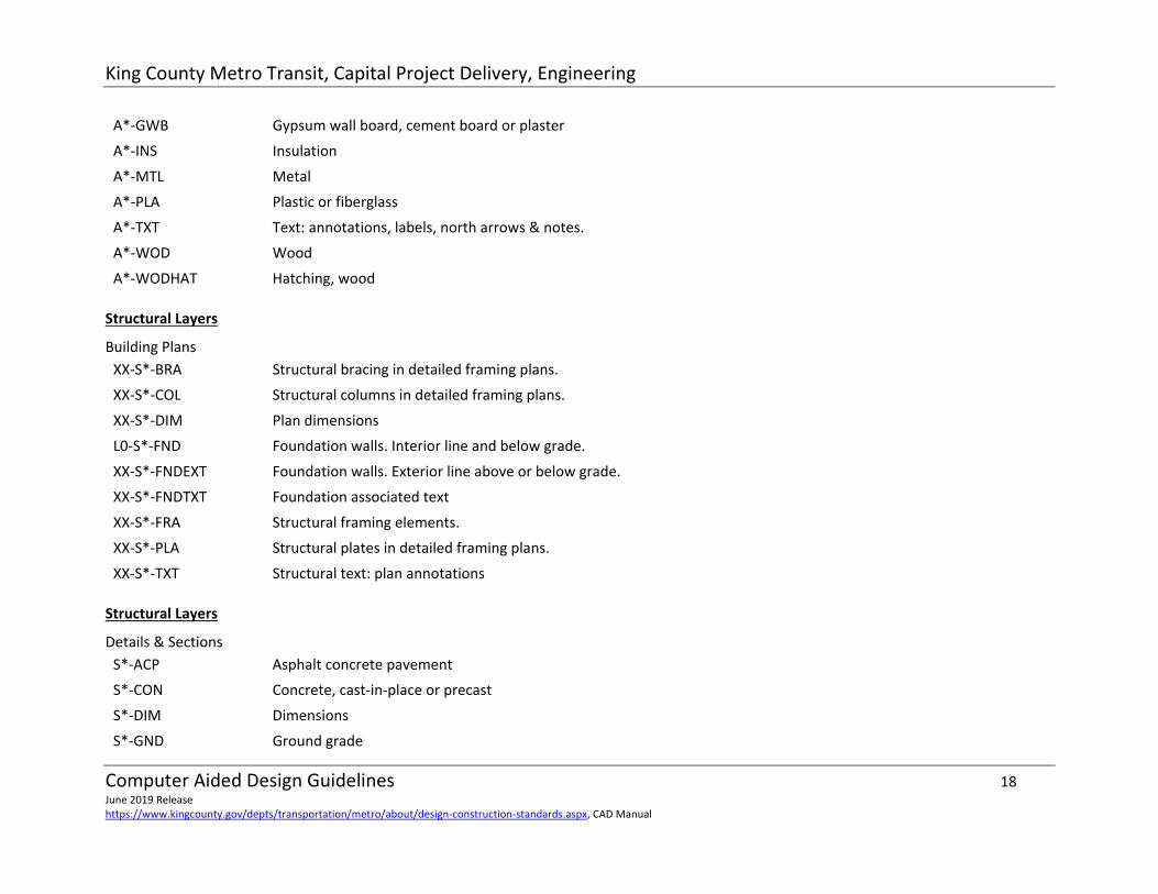
A*‐GWB Gypsum wall board, cement board or plaster
A*‐INS Insulation
A*‐MTL Metal
A*‐PLA Plastic or fiberglass
A*‐TXT Text: annotations, labels, north arrows & notes.
A*‐WOD Wood
A*‐WODHAT Hatching, wood
Structural Layers
Building Plans XX‐S*‐BRA Structural bracing in detailed framing plans.
XX‐S*‐COL Structural columns in detailed framing plans.
XX‐S*‐DIM Plan dimensions
L0‐S*‐FND Foundation walls. Interior line and below grade.
XX‐S*‐FNDEXT Foundation walls. Exterior line above or below grade.
XX‐S*‐FNDTXT Foundation associated text
XX‐S*‐FRA Structural framing elements.
XX‐S*‐PLA Structural plates in detailed framing plans.
XX‐S*‐TXT Structural text: plan annotations
Structural Layers
Details & Sections S*‐ACP Asphalt concrete pavement
S*‐CON Concrete, cast‐in‐place or precast
S*‐DIM Dimensions
S*‐GND Ground grade

King County Metro Transit, Capital Project Delivery, Engineering
Computer Aided Design Guidelines 19 June 2019 Release https://www.kingcounty.gov/depts/transportation/metro/about/design‐construction‐standards.aspx, CAD Manual
S*‐GRV Gravel
S*‐GWB Gypsum wall board, cement board or plaster
S*‐MTL Metal
S*‐PLA Plastic or fiberglass
S*‐TXT Text: annotations, labels, north arrows & notes.
S*‐WOD Wood
S*‐WODHAT Hatching, wood
Mechanical Layers
Building Plans XX‐M*‐DRN Drains: roof drains, rain leaders, floor drains, industrial waste, etc.
XX‐M*‐DRNTXT Drains associated text
XX‐M*‐DIM Plan dimensions
XX‐M*‐EQP Mechanical equipment: pumps, cranes, etc. Not HVAC
XX‐M*‐EQPTXT Mechanical equipment associated text
XX‐M*‐FIR Fire protection system piping
XX‐M*‐FIRTXT Fire protection system text
XX‐M*‐FIRSYM Fire protection system sprinklers
XX‐M*‐HEQ HVAC equipment: air handling units, ventilators, controls, etc
XX‐M*‐HEQTXT HVAC equipment associated text
XX‐M*‐HVD HVAC system ductwork: non‐defined
XX‐M*‐HVDTXT HVAC system ductwork associated text
XX‐M*‐HVDR HVAC system ductwork: return air
XX‐M*‐HVDRTXT HVAC system ductwork: return air associated text
XX‐M*‐HVDS HVAC system ductwork: supply air

King County Metro Transit, Capital Project Delivery, Engineering
Computer Aided Design Guidelines 20 June 2019 Release https://www.kingcounty.gov/depts/transportation/metro/about/design‐construction‐standards.aspx, CAD Manual
XX‐M*‐HVDSTXT HVAC system ductwork: supply air associated text
XX‐M*‐LFT Hydraulic lifts: platform lifts, axle lifts, surface lifts, ancillary lift controls ,etc.
XX‐M*‐LFTTXT Hydraulic lifts associated text
XX‐M*‐PIP Piping system: non‐defined
XX‐M*‐PIPTXT Piping system associated text
XX‐M*‐PLG Plumbing system: domestic water (potable & non‐pot), waste, drains, vents
XX‐M*‐PLGTXT Plumbing system associated text
XX‐M*‐TXT Mechanical text: plan annotations
XX‐M*‐VEH Vehicle exhaust systems: ductwork, reels, fans, etc.
XX‐M*‐VEHTXT Vehicle exhaust systems associated text
Mechanical Layers
Details & Sections M*‐DIM Dimensions
M*‐EQP Mechanical equipment
M*‐FIR Fire protection system piping
M*‐HEQ HVAC equipment
M*‐HVD HVAC system ductwork: non‐defined
M*‐LFT Lifts
M*‐PIP Piping system: non‐defined
M*‐PLG Plumbing system: non‐defined.
M*‐TXT Text: annotations, labels, north arrows & notes.
M*‐VEH Vehicle exhaust systems

King County Metro Transit, Capital Project Delivery, Engineering
Computer Aided Design Guidelines 21 June 2019 Release https://www.kingcounty.gov/depts/transportation/metro/about/design‐construction‐standards.aspx, CAD Manual
Electrical Layers
Building Plans XX‐E*‐COM Communications: telephone, data, intercoms. This includes ceiling, wall, and floor plugs (jacks).
XX‐E*‐COMCND Communications: conduit
XX‐E*‐COMEQP Communications: control consoles, receivers, and panel boards.
XX‐E*‐COMTXT Communications associated text
XX‐E*‐DIM Plan dimensions
XX‐E*‐ELTG Emergency lighting systems surface features; wall, floor, pendent and ceiling mounted fixtures.
XX‐E*‐ELTGCND Emergency lighting systems: conduit
XX‐E*‐ELTGEQP Emergency lighting systems: wall toggle and dimmer switches, low voltage relay panels and emergency control panels.
XX‐E*‐ELTGTXT Emergency lighting systems associated text
XX‐E*‐EPNL Generator fed power / lighting
XX‐E*‐EPNLCND Feeders (Homeruns) for emergency power panels
XX‐E*‐EPNLTXT Text for emergency panel
XX‐E*‐EQP Powered equipment, HVAC , (any hardwired equipment to a power source)
XX‐E*‐EQPCND Powered equipment: conduit, homeruns, j‐boxes
XX‐E*‐EQPEQP Powered equipment, HVAC switches, thermostats, etc.
XX‐E*‐EQPTXT Powered equipment associated text
XX‐E*‐ FPS Fire protection devices / appliances, facp, etc
XX‐E*‐FPSCND Conduit for above
XX‐E*‐FPSTXT Text for above
XX‐E*‐LTG Light fixtures, non‐emergency
XX‐E*‐LTGCND Light fixtures: conduit
XX‐E*‐LTGEQP Light fixtures: switches, contactor panels, motion sensors, for normal lights
XX‐E*‐LTGTXT Light fixture: Text for normal lights

King County Metro Transit, Capital Project Delivery, Engineering
Computer Aided Design Guidelines 22 June 2019 Release https://www.kingcounty.gov/depts/transportation/metro/about/design‐construction‐standards.aspx, CAD Manual
XX‐E*‐PNL Power panels 480/277, 120/240, and 120/208 (includes “lighting” power panels)
XX‐E*‐PNLCND Feeders for power panels
XX‐E*‐PNLCNDTXT Feeder text for power panels
XX‐E*‐PNLPLUG Ceiling level panels ( Plug Bus )
XX‐E*‐PNLTXT Electrical panel associated text
XX‐E*‐PWR Receptacles
XX‐E*‐PWRCND Receptacles: conduit
XX‐E*‐PWRTXT Receptacle associated text
XX‐E*‐PWREQP Cord‐plugged equipment
XX‐E*‐SCR Security equipment: card readers, cameras, alarms, sensors
XX‐E*‐SCRCND Security equipment: conduit
XX‐E*‐SCRTXT Security equipment associated text
XX‐E*‐UGE Underground power conduit
XX‐E*‐UGECOM Underground communication circuit
XX‐E*‐UGEDAT Underground data conduit
XX‐E*‐UGETEL Underground telephone conduit
XX‐E*‐UGEEQP Equipment in vaults (transformers, etc...)
XX‐E*‐UGEVLT Vaults, handholes, etc...
XX‐E*‐UGETXT Text for above
Electrical Layers
Details & Sections E*‐CND Conduit
E*‐DIM Dimensions
E*‐EQP Electrical equipment

King County Metro Transit, Capital Project Delivery, Engineering
Computer Aided Design Guidelines 23 June 2019 Release https://www.kingcounty.gov/depts/transportation/metro/about/design‐construction‐standards.aspx, CAD Manual
E*‐TXT Text: annotations, labels, north arrows & notes.
Electrical Layers
One Line, SCADA & Panel Schedules
E*‐TXT Text
E*‐LIN Lines
Trolley Layers
Street Overhead
T*‐RES Resultant load
T*‐RESTXT Resultant load text
T*‐SPWLINE
T‐SPWSYM
Span wire
Span wire equipment
T*‐SPWTXT Span wire text
T*‐STRSYM Trolley support structure, present at ground level
T*‐STRFND Trolley support structure, foundation below grade
T*‐STRSPW Trolley support structure, at span wire level only (mast arms)
T*‐STRTXT Trolley support structure text
T*‐TWNLINE Trolley negative run wire
T*‐TWPLINE Trolley positive run wire
T*‐TXT General trolley system text
Trolley Layers
Yard System at Atlantic Base

King County Metro Transit, Capital Project Delivery, Engineering
Computer Aided Design Guidelines 24 June 2019 Release https://www.kingcounty.gov/depts/transportation/metro/about/design‐construction‐standards.aspx, CAD Manual
T*‐RES‐53 Resultant load
T*‐RESTXT‐53 Resultant load text
T*‐SPWLINE‐53 Span wire
T*‐SPWTXT‐53 Span wire text
T*‐STRSYM‐53 Trolley support structure, present at ground level
T*‐STRFND‐53 Trolley support structure, foundation below grade
T*‐STRSPW‐53 Trolley support structure, at span wire level only
T*‐STRTXT‐53 Trolley support structure text
T*‐TWNLINE‐53 Trolley negative run wire
T*‐TWPLINE‐53 Trolley positive run wire
Trolley Layers
Inside Wiring at Atlantic Base
L1‐T*‐CDP Positive wires in conduit
L1‐T*‐CDN Negative wires in conduit
L1‐T*‐CTW Control wiring, low and high voltage
L1‐T*‐GND Ground Wire
L2‐T*‐TWN Trolley negative run wire
L2‐T*‐TWP Trolley positive run wire
L*‐T*‐***TXT Extension for associated text layer
Substation Site Codes 00 – Not Site Specific
01 – Lower Queen Anne
02 – Upper Queen Anne #2
03 – Upper Queen Anne #3
04 ‐ Madrona
05 ‐ Bellevue

King County Metro Transit, Capital Project Delivery, Engineering
Computer Aided Design Guidelines 25 June 2019 Release https://www.kingcounty.gov/depts/transportation/metro/about/design‐construction‐standards.aspx, CAD Manual
06 ‐ Capitol
07 ‐ Marion
08 – Bob Sharp (previously “University”)
09 – First Hill
10 – Mt Baker
11 – M.L.K.
12 ‐ Collins
13 – North Broadway
14 – Atlantic #1
15 ‐ Atlantic #2
16 ‐ Market
17 ‐ West Woodland
18 ‐ Meridian
19 ‐ Montlake
20 – Waterfront Street Car
21 ‐ Central
22 – Broad St.
23 – Beacon Hill
24 ‐ Maple
25 – Rainier Beach
26 ‐ Roxbury
27 ‐ Brighton
28 ‐ Columbia
29 ‐ Letitia
30 – Davy Jones (45th & I‐5 On Ramp)
31 ‐ Allison
32 ‐ Galer
33 – Doug James
35 – S. Jackson
36 ‐ Olive
40 – International Dist. Rect. (Tunnel)
41 – University St Rect. (Tunnel)
42 – Convention Pl. Rect. (Tunnel)
43 – Westlake (Monorail)
44 – Seattle Center (Monorail)
50 – East Base
51 – South Base
52 – North Base
53 – Atlantic Base
54 – DC Cont. Pnl. 2 Atlantic FW
55 – Central Base
56 – Ryerson Base
57 – Bellevue Base
58 ‐ N.R.V.
59 – WFSC Barn
60 – International Dist. Station
61 – University St. Station
62 – Convention Pl. Station
63 – Pioneer Station
64 – Westlake
*Traction power wiring layers will be identified under the Trolley layers.

King County Metro, Capital Project Delivery
Computer Aided Design Guidelines 26 June 2019 Release https://www.kingcounty.gov/depts/transportation/metro/about/design‐construction‐standards.aspx, CAD Manual
Pen Settings/Plotter Configuration Standard ACAD Color Associations:
Very fine = Existing plan, section, detail & elevation elements, hatching. 8,10,11,21,31,41,51,61,71,81,91
Fine = Existing plan, section, detail & elevation element highlights, graphic line work, hatching. 1,7,12,22,32,42,52,62,72,82,92
Medium = Text, dimensions 4,13,23,33,43,53,63,73,83,93
Heavy = Text headings, reference text highlighting, demolition highlighting, new work 2,6,14,15,24,25,34,35,44,45,64,65,74,75,84,85,84,95
Bold = New work, plan headings, graphic line work 3,5,18,28,38,48,58,68,78,88,98
Very Bold = At user's discretion 19,29,39,49,59,69,79,89,99
Extreme Bold = At user's discretion 20,30,40,50,60,70,80,90
Screening = Gray scale for solid hatching, limited use for line work 100 ‐ 109: white 110 ‐ 119: 10% 120 ‐ 129: 20% 130 ‐ 139: 30% 140 ‐ 149: 40% 150 ‐ 159: 50% 160 ‐ 169: 60% 170 ‐ 179: 70% 180 ‐ 189: 80% 190 ‐ 199: 90%

King County Metro, Capital Project Delivery
Computer Aided Design Guidelines 27 June 2019 Release https://www.kingcounty.gov/depts/transportation/metro/about/design‐construction‐standards.aspx, CAD Manual
Drawing Stamping Procedures General
All drawings and Specification included in a contract shall have an engineers stamp.
Drawings issued for “Information Only” do not require a stamp.
Who Stamps
The licensed engineer (or architect) responsible for the design reflected on the drawing is to stamp the sheet.
Usually only one stamp will be on an individual drawing. If more than one discipline is significantly included on a drawing, a second stamp for the second discipline may be required. Alternately, the supervisor or managing engineer may elect to take responsibility for stamping the drawing. Double stamping will not be a practice. All in‐house design drawings shall be co‐signed by the engineering supervisor before 100% release, see title block section for appropriate signature locations.
Drawing Submittals Pre 90% Review Package
Title block information filled‐out to include Facility Name, Project Title, Drawing Description Title and Drawing Number.
Add Consultant Logo (if applicable).
Add “For Information Only” stamp.
90% Review Package
Add to title block information: Contract Number, EWR Number, Scale, Designed by, Drawn by, Checked by and Sheet Numbers.
Add “For Information Only 90% Review” stamp. Permit Submittals
Remove [review status] stamp, note Permit submittal with date in the revision block. Drawings must be signed.

King County Metro, Capital Project Delivery
Computer Aided Design Guidelines 28 June 2019 Release https://www.kingcounty.gov/depts/transportation/metro/about/design‐construction‐standards.aspx, CAD Manual
100% Deliverables: Bid Documents Drawings
Complete title block information.
Add Engineers stamps.
Consultant Drawings must show approvals by King County Engineering as well as Authorizing Engineer or Archittect.
All sealed Drawings must be approved by King County’s Capital Project Delivery Engineering Division Manager.
Addendum’s/Contract Changes
In‐house projects must be stamped by the Project Design Engineer.
Consultants shall stamp drawings that they produce.
Document changes, additional drawings produced by Design Section personnel shall be stamped as described above.
Consultant Drawings
We do not stamp, only approve.
See the Signing and Stamping policy.
CAD Deliverables Electronic CAD file deliverables as defined by an approved Scope of Work shall include the following:
CAD files.
X‐REF files.
Non‐standard shape/font files, where present.
King County Metro, Capital Project Delivery
Computer Aided Design Guidelines 29 June 2019 Release https://www.kingcounty.gov/depts/transportation/metro/about/design‐construction‐standards.aspx, CAD Manual
Pen settings provided as a Color Dependent Plot Style Table (CTB) file, or chart of pen colors, pen widths and patterns in ASCII text, Word or Excel electronic file.
Hardcopy and electronic index of drawings (G101 = xxx.dwg, etc.) with an X‐REF matrix.
PDF files shall be saved in black and white line types and in only 22” x 34” D‐size format. ALL drawings shall be compiled into one single file, in the same sequence as stated in the drawing index, unless instructed otherwise.

King County Metro, Capital Project Delivery
Computer Aided Design Guidelines 30 June 2019 Release https://www.kingcounty.gov/depts/transportation/metro/about/design‐construction‐standards.aspx, CAD Manual
Revision History Version 2
2.0 12/3/01 Content rewritten
2.1 9/17/02 Drawing Package Organization revised with new drawing numbering schema.
2.15 3/25/03 CAD format clarified, security layers added. CAD deliverables requirements clarified
2.2 5/22/03 Drawing number for Area Location number clarified. Section label and detail labels ‐ added underline to text.
2.3 1/30/04 Trolley Layers revised
2.4 4/21/04 All layers revised
2.5 11/2/05 Added (restored) underground electrical layers
2.5.1 4/12/06 revised Internet URL for CAD.PDF
2.5.2 4/25/06 Fixed detail & section numbering/lettering graphics & text
2.5.3 5/31/06 Change AutoCAD file format to AutoCAD 2004
2.5.5 10/2008 Change AutoCAD file format to AutoCAD 2007 & miscellaneous updates
2.5.6 10/2009 Change section & plan bubble to half bubble (p. 10)
2.5.7 03/2012 File location noted
2.5.8 05/2013 Revisions to current CAD version, procedural changes, layer names.
2.5.9 08/2013 Revision to current ACAD, other updates to current standards.
2.5.10 09/2018 Revision to title block/border (pp 6 – 7) and URL of manual.
2.5.11 11/2018 Revision to title block/border (pp 6 – 7) as Metro Transit becomes a Department from a Division on 1/1/2019, added PDF deliverables requirements
2.5.12 12/2018 Updates to graphics, text clarifications.
2.5.13 6/2019 Revision to title block/border (pp. 6 – 7), text clarifications, updated URL location of CAD.pdf