computer architecture it0205 - srm · pdf filepipeline register –same as cdr. ... apply...
TRANSCRIPT

COMPUTER ARCHITECTURE‐ IT0205
M.Thenmozhi/Kayalvizhi Jayavel/M.B.PanbuAsst.Prof.(Sr.G)/Asst.Prof.(Sr.G)/Asst.Prof.(O.G)
Department of ITSRM University, Kattankulathur
1

Disclaimer
The contents of the slides are solely for the purpose of teaching students at SRM University. All copyrights and Trademarks of organizations/persons apply even if not specified explicitly.
2

UNIT‐II : Microprogramming and CPU
Control Memory and Address Sequencing
Design of Control unit
CPU– General Register Organization
– Stack Organization
– Addressing Modes
– RISC
3

Control Memory
Hardwired control – control signals are generated by conventional logic circuits
Microprogrammed control – control signals are generated by binary control variables stored in control memory
Control memory – memory that is part of control unit
Microinstruction – every word in control memory is a microinstruction
Control MAR – specifies the address of the microinstruction
4
5
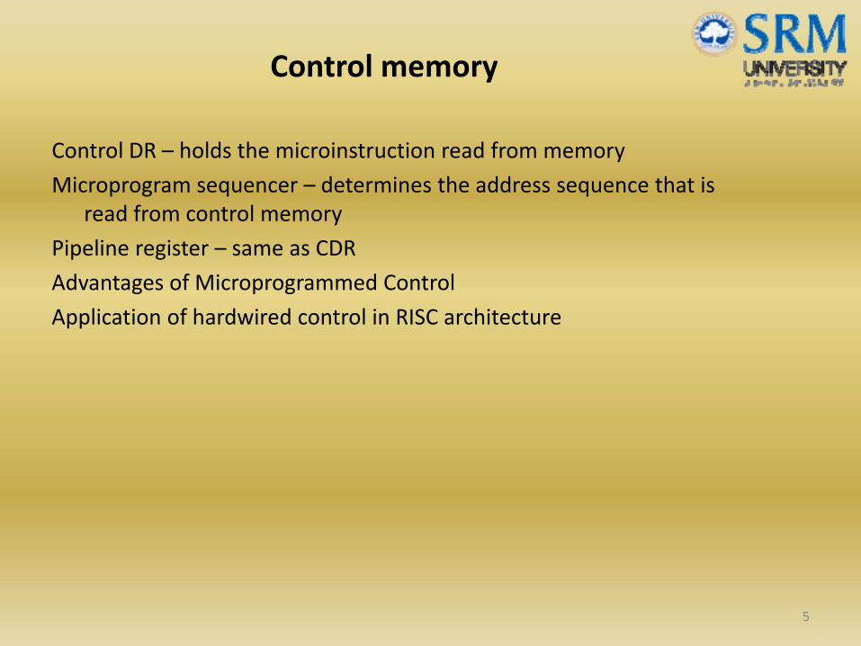
Control memory
Control DR – holds the microinstruction read from memory
Microprogram sequencer – determines the address sequence that is read from control memory
Pipeline register – same as CDR
Advantages of Microprogrammed Control
Application of hardwired control in RISC architecture

Routine – group of microinstructions stored in control memory
An initial address is loaded into the CAR during system start‐up
Fetch routine – fetches the initial address
Next step is to generate the microoperations that execute the instruction fetched from memory
Mapping process – rule that transforms the instruction code into a control memory address
Address sequencing diagram shows four different paths from which the CAR receives the address
6
Address sequencing

7
8
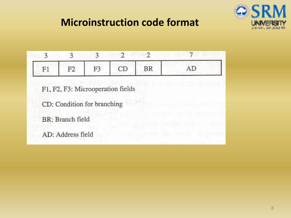
Microinstruction code format

Design of control unit
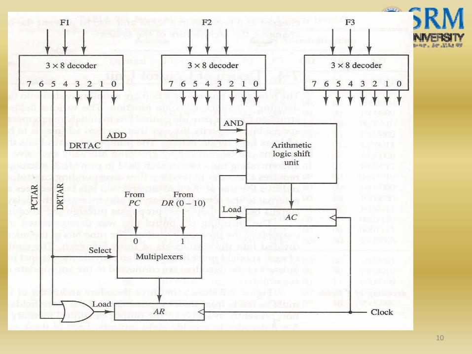
Each microoperation field requires a decoder to produce the corresponding control signals
A max. of three microoperations can be specified in a microinstruction
Basic components of a microprogrammed control unit are the control memory and the circuits that select the next address
The address selection part is called the microprogram sequencer
Block diagram for decoding of microoperation fields is given in the next slide
9
10

Central Processing Unit (CPU)
General register organization – registers communicate with each other not only for direct data transfers, but also while performing various microoperations
Output of each register is connected to two multiplexers to form the two buses A and B
The selection lines in each multiplexer select one register
The A and B buses form inputs to a ALU
The register that receives the information from the output bus is selected by a decoder
11

12

Stack organization
Stack – storage device that uses LIFO concept
Stack pointer – register that holds the address for the stack (points to the top of the stack)
Two operations – Insertion (PUSH) and Deletion (POP)
Register Stack – collection of finite number of memory words or registers
Reverse Polish Notation – used by stack organization (e.g) A*B+C*D can be written as AB*CD*+
Demonstration of evaluation of arithmetic expressions using chalk and talk
13
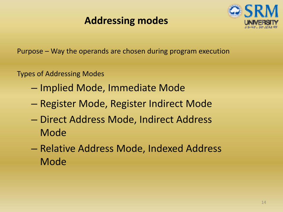
Addressing modes
Purpose – Way the operands are chosen during program execution
Types of Addressing Modes
– Implied Mode, Immediate Mode
– Register Mode, Register Indirect Mode
– Direct Address Mode, Indirect Address Mode
– Relative Address Mode, Indexed Address Mode
14

Reduced Instruction Set Computer (RISC)
Characteristic features
– Relatively few instructions
– Relatively few addressing modes
– Memory access limited to load and store instructions
– All operations done within the registers of the CPU
– Fixed length instruction format
– Hardwired control15

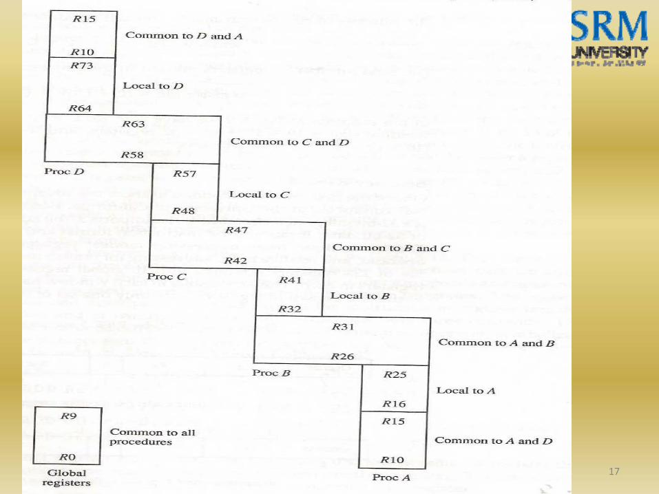
Overlapped register windows
Purpose – To speed up procedure call and return during the presence of relatively large number of registers in the processor unit
Organization of register windows will have the following relationships
– G = no. of global registers
– L = no. of local registers in each window
– C = no. of registers common to two windows
– W = no. of windows
– Window size = L+2C+G, Register File =(L+C)W+G 16
17

Definitions of various terminologies with respect to control memory
What is the use of Fetch routine in Address sequencing?
Microinstruction code format
Procedure for selecting binary variables for a given microoperation
Evaluation of arithmetic expression using Stack operations and RPN
Comparison of different addressing modes
Apply Overlapped register windows to explain RISC architecture
18