computer arithmetic, multiplexers prof. sin-min lee department of computer science
Post on 21-Dec-2015
229 views
TRANSCRIPT

Computer Arithmetic, Multiplexers
Prof. Sin-Min Lee
Department of Computer Science


Bit-Serial and Ripple-Carry Adders
x y c s ---------------- 0 0 0 0 0 1 0 1 1 0 0 1 1 1 1 0
Inputs Outputs
HA
x y
c
s
Half-adder (HA): Truth table and block diagram
x y c c s ---------------------- 0 0 0 0 0 0 0 1 0 1 0 1 0 0 1 0 1 1 1 0 1 0 0 0 1 1 0 1 1 0 1 1 0 1 0 1 1 1 1 1
Inputs Outputs
c out c in
out in x
y
s
FA
Full-adder (FA): Truth table and block diagram


Half-Adder Implementations
c
s
(b) NOR-gate half-adder.
x
y
x
y
(c) NAND-gate half-adder with complemented carry.
x
y
c
s
s
cx
y
x
y
(a) AND/XOR half-adder._
_
_c
Three implementations of a half-adder.

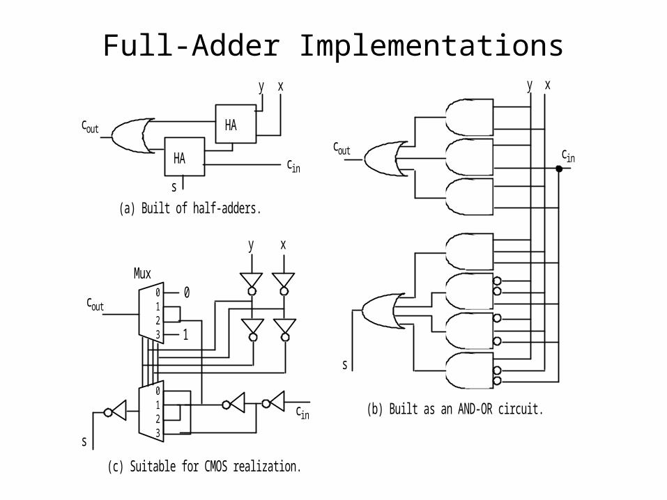
Full-Adder Implementations
HA
HA
xy
cin
cout
(a) Built of half-adders.
s
(b) Built as an AND-OR circuit.
(c) Suitable for CMOS realization.
cout
s
c in
xy
0 1 2 3
0 1 2 3
xy
c in
cout
s
0
1
Mux


Converting whole part w: (105)ten = (?)fiveRepeatedly divide by five Quotient Remainder
105 0 21 1 4 4 0
Therefore, (105)ten = (410)five
Converting fractional part v: (105.486)ten = (410.?)fiveRepeatedly multiply by five Whole Part Fraction
.486 2 .430 2 .150 0 .750 3 .750 3 .750
Therefore, (105.486)ten (410.22033)five
Radix Conversion: Old-Radix Arithmetic

Radix Conversion: New-Radix Arithmetic
Converting whole part w: (22033)five = (?)ten
((((2 5) + 2) 5 + 0) 5 + 3) 5 + 3
|-----| : : : :
10 : : : :
|-----------| : : :
12 : : :
|---------------------| : :
60 : :
|-------------------------------| :
303 :
|-----------------------------------------|
1518
Converting fractional part v: (410.22033)five = (105.?)ten (0.22033)five 55 = (22033)five = (1518)ten
1518 / 55 = 1518 / 3125 = 0.48576Therefore, (410.22033)five = (105.48576)ten
Horner’s rule is also applicable: Proceed from right to left and use division instead of multiplication
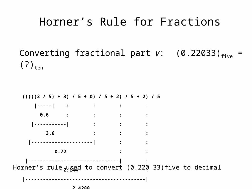
Horner’s Rule for Fractions
Converting fractional part v: (0.22033)five = (?)ten
(((((3 / 5) + 3) / 5 + 0) / 5 + 2) / 5 + 2) / 5
|-----| : : : :
0.6 : : : :
|-----------| : : :
3.6 : : :
|---------------------| : :
0.72 : :
|-------------------------------| :
2.144 :
|-----------------------------------------|
2.4288
|-----------------------------------------------|
0.48576
Horner’s rule used to convert (0.220 33)five to decimal

Signed-Magnitude Representation
0000 0001 1111
0010 1110
0011 1101
0100 1100
1000
0101 1011
0110 1010
0111 1001
0 +1
+3
+4
+5
+6 +7
-7
-3
-5
-4
-0 -1
+2-
+ _
Bit pattern (representation)
Signed values (signed magnitude)
+2 -6
Increment Decrement
Four-bit signed-magnitude number representation system for integers

Two’s- and 1’s-Complement Numbers
0000 0001 1111
0010 1110
0011 1101
0100 1100
1000
0101 1011
0110 1010
0111 1001
+0 +1
+3
+4
+5
+6 +7
-1
-5
-3
-4
-8 -7
-6
+ _
Unsigned representations
Signed values (2’s complement)
+2 -2 Two’s complement = radix complement system for r = 2
M = 2k
2k – x = [(2k – ulp) – x] + ulp = xcompl + ulp
Range of representable numbers in with k whole bits:
from –2k–1 to 2k–1 – ulp
A 4-bit 2’s-complement number representation system for integers.
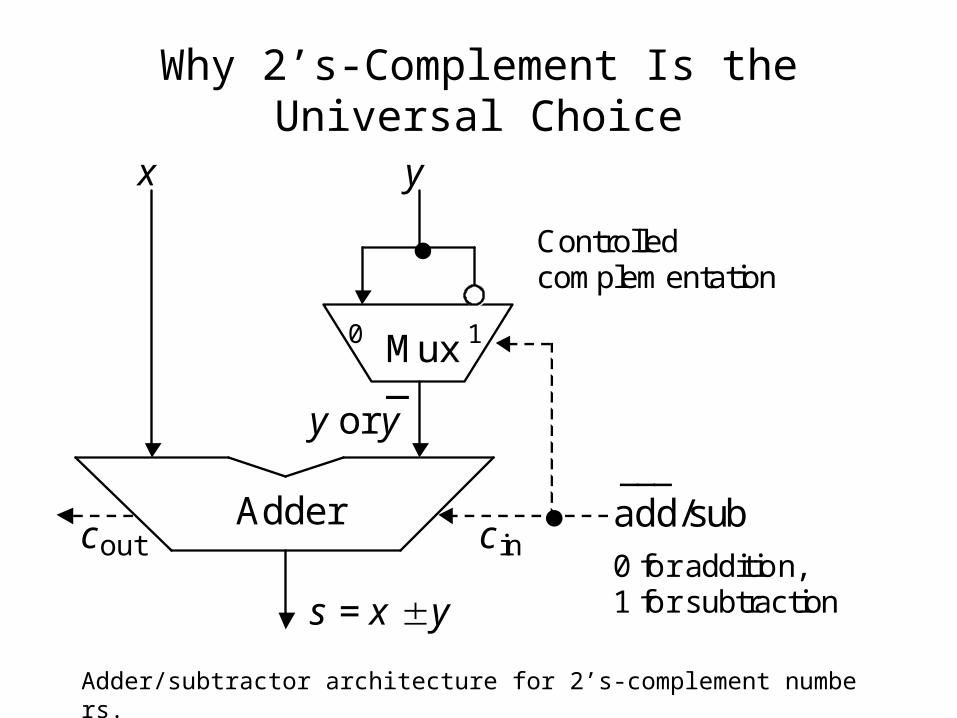
Why 2’s-Complement Is the Universal Choice
Mux
Adder
0 1
x y
y or y _
s = x y
add/sub ___
c in
Controlled complementation
0 for addition, 1 for subtraction
c out
Adder/subtractor architecture for 2’s-complement numbers.

Signed-Magnitude vs 2’s-Complement
Adder cc
s
x ySign x Sign y
Sign
Sign s
Selective Complement
Selective Complement
out in
Comp x
Control
Comp s
Add/Sub
Compl x
___ Add/Sub
Compl s
Selective complement
Selective complement
Two’s-complement adder/subtractor needs very little hardware other than a simple adder
Fig. 2.7
Mux
Adder
0 1
x y
y or y _
s = x y
add/sub ___
c in
Controlled complementation
0 for addition, 1 for subtraction
c out
Signed-magnitude adder/subtractor is significantly more complex than a simple adder

Some commonly used components
• Decoders: n inputs, 2n outputs.– the inputs are used to select which output is
turned on. At any time exactly one output is on.
• Multiplexors: 2n inputs, n selection bits, 1 output.– the selection bits determine which input will
become the output.
• Adder: 2n inputs, 2n outputs. – Computer Arithmetic.

Multiplexer
• “Selects” binary information from one of many input lines and directs it to a single output line.
• Also known as the “selector” circuit,• Selection is controlled by a particular set of
inputs lines whose # depends on the # of the data input lines.
• For a 2n-to-1 multiplexer, there are 2n data input lines and n selection lines whose bit combination determines which input is selected.

MUX
2n DataInputs
DataOutput
InputSelect
n
Enable

Remember the 2 – 4 Decoder?
S1
S0
Sel(3)
Sel(2)
Sel(1)
Sel(0)
Mutually Exclusive(Only one O/P asserted
at any time

4 to 1 MUX
2 - 4 Decoder
Control
DataFlow
D3:D0
4
Sel(3:0)
4
S1:S0
2
Dout

4-to-1 MUX (Gate level)
Three of these signal inputs will always be 0.
The other will depend on the data value selected
Control Section

• Until now, we have examined single-bit data selected by a MUX. What if we want to select m-bit data/words? Combine MUX blocks in parallel with common select and enable signals
• Example: Construct a logic circuit that selects between 2 sets of 4-bit inputs (see next slide for solution).
Multiplexer (cont.)
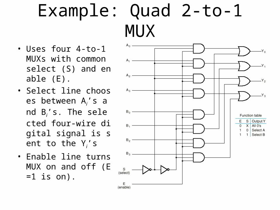
Example: Quad 2-to-1 MUX
• Uses four 4-to-1 MUXs with common select (S) and enable (E).
• Select line chooses between Ai’s and Bi’s. The selected four-wire digital signal is sent to the Yi’s
• Enable line turns MUX on and off (E=1 is on).

Implementing Boolean functions with Multiplexers
• Any Boolean function of n variables can be implemented using a 2n-1-to-1 multiplexer. A MUX is basically a decoder with outputs ORed together, hence this isn’t surprising.
• The SELECT signals generate the minterms of the function.
• The data inputs identify which minterms are to be combined with an OR.

Example
•F(X,Y,Z) = X’Y’Z + X’YZ’ + XYZ’ + XYZ = Σm(1,2,6,7)•There are n=3 inputs, thus we need a 2222-to-1 MUX-to-1 MUX•The first n-1 (=2) inputs serve as the selection linesThe first n-1 (=2) inputs serve as the selection lines

Efficient Method for implementing Boolean functions• For an n-variable function (e.g., f(A,B,C,D)):
– Need a 2n-1 line MUX with n-1 select lines.– Enumerate function as a truth table with consistent
ordering of variables (e.g., A,B,C,D)– Attach the most significant n-1 variables to the n-1
select lines (e.g., A,B,C)– Examine pairs of adjacent rows (only the least
significant variable differs, e.g., D=0 and D=1).– Determine whether the function output for the (A,B,C,0)
and (A,B,C,1) combination is (0,0), (0,1), (1,0), or (1,1).– Attach 0, D, D’, or 1 to the data input corresponding to
(A,B,C) respectively.

Another Example
• Consider F(A,B,C) = m(1,3,5,6). We can implement this function using a 4-to-1 MUX as follows.
• The index is ABC. Apply A and B to the S1 and S0 selection inputs of the MUX (A is most sig, S1 is most sig.)
• Enumerate function in a truth table.

MUX Example (cont.)
A B C F
0 0 0 0
0 0 1 1
0 1 0 0
0 1 1 1
1 0 0 0
1 0 1 1
1 1 0 1
1 1 1 0
When A=B=0, F=CWhen A=B=0, F=C
When A=0, B=1, When A=0, B=1, F=CF=CWhen A=1, B=0, When A=1, B=0, F=CF=CWhen A=B=1, When A=B=1, F=C’F=C’

MUX implementation of F(A,B,C) = m(1,3,5,6)
AA
BB
CC
CC
CC
C’C’
FF
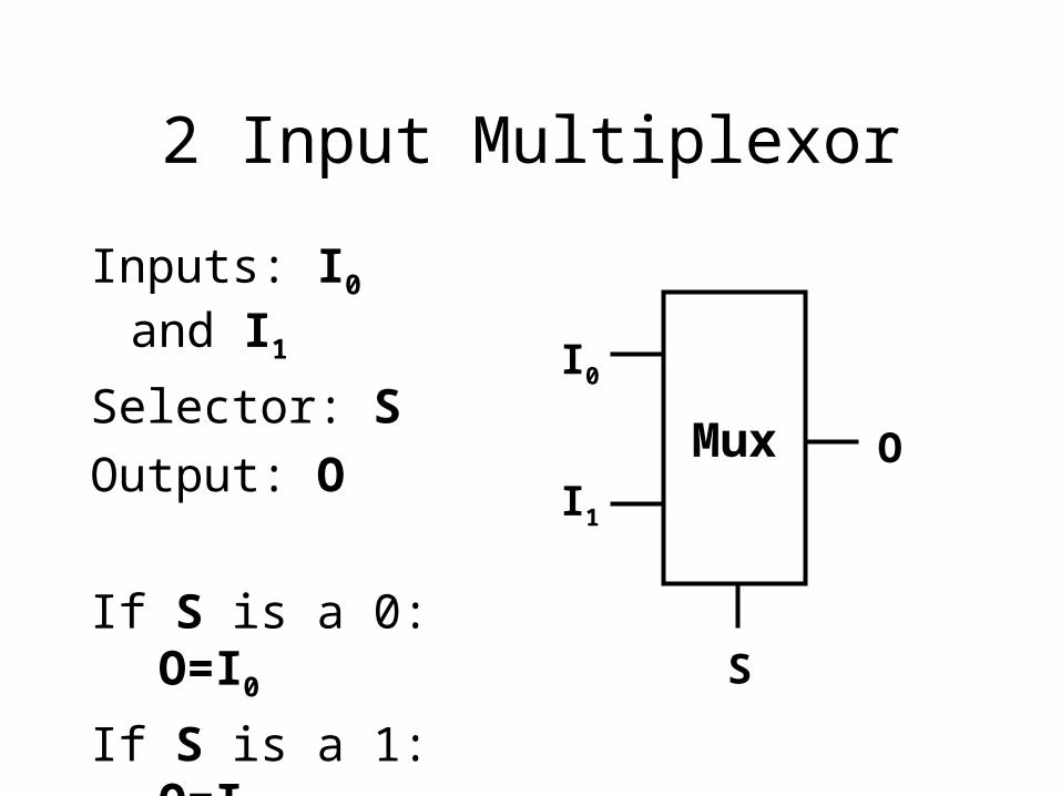
2 Input Multiplexor
Inputs: I0 and I1
Selector: S
Output: O
If S is a 0: O=I0
If S is a 1: O=I1
Mux
I0
I1
O
S

2-Mux Logic Design
I1I0S
O
I0 && !S
I1 && S

4 Input Multiplexor
Inputs: I0 I1 I2 I3
Selectors: S0 S1
Output: O Mux
I0
I2
O
S0
S0 S1 O
0 0 I0
0 1 I1
1 0 I2
1 1 I3
I1
I3
S1

One Possible 4-Mux
2-Decoder
I0
I1
I2
I3
S0
S1O

Adder
• We want to build a box that can add two 32 bit numbers.– Assume 2s complement representation
• We can start by building a 1 bit adder.

Addition
• We need to build a 1 bit adder– compute binary addition of 2 bits.
• We already know that the result is 2 bits.A B O0 O1
0 0 0 0
0 1 0 1
1 0 0 1
1 1 1 0
A
+ B
O0 O1
This is addition!
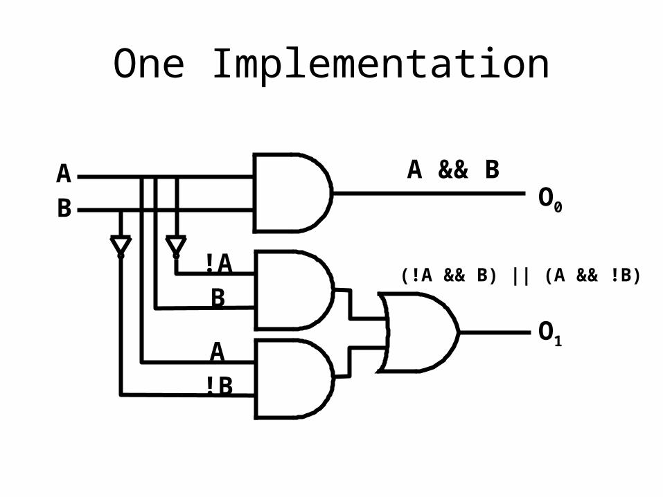
One Implementation
AB O0
!AB
A!B
O1
A && B
(!A && B) || (A && !B)

Binary addition and our adder
What we really want is something that can be used to implement the binary addition algorithm. – O0 is the carry– O1 is the sum
01001+ 01101
10110
11 Carry

What about the second column?
• We are adding 3 bits– new bit is the carry from the first column.– The output is still 2 bits, a sum and a carry
01001+ 01101
10110
11 Carry

Truth Table for Addition
A B Carry
In
Carry
Out
Sum
0 0 0 0 0
0 0 1 0 1
0 1 0 0 1
0 1 1 1 0
1 0 0 0 1
1 0 1 1 0
1 1 0 1 0
1 1 1 1 1