computer-assisted fault-tree construction using a knowledge-based approach
TRANSCRIPT

112 IEEE TRANSACTIONS ON RELIABILITY, VOL. 43, NO. 1, 1994 MARCH
Computer-Assisted Fault-Tree Construction Using A Knowledge-Based Approach
Margaret S. Elliott, Student Member IEEE University of California, Irvine
Key Words - Artificial intelligence, Expert system, Fault-tree analysis, Knowledge-based system, Minimal cut set, Obj&+riented programming, Reliability analysis
Reader A i d s - General purpose: Widen state of the art, tutorial Special math needed for explanations: Probability, Boolean algebra Special math needed to use results: Same Results useful to: Reliability & safety engineers, Knowledge
engineers
Summary & Conclusions - This paper presents a knowledge- based approach to analyziug fault-trees of engineering systems. This appmch can be used to build a fault-tree from a graphical func- tional black diagram (using reduction for replicated events), to am- pute minimal cut sets, and to analyze the system for redesign sug- gestions. An implementation of this approach in a debased language is presented. The results are compared with manually prepared reliability reports on an electrical power system and an hydraulic system. The knowledge-based system outperforms the manual procedure in timeliness & accuracy.
1. INTRODUCTION
Fault-tree analysis is widely used for obtaining qualitative & quantitative reliability and system-safety assessments of com- plex systems. This process consists of constructing a logic diagram (fault-tree) that represents the causal relationships of basic failures (basic events) contributing to a predetermined system failure (TOP event). The fault-tree forms the basis of analyzing the system design and assuring system-safety re- quirements. Fault-tree analysis results need to be precise to en- sure reliable designs. The accuracy of fault-tree construction directly affects fault-tree analysis results. However, manual fault-tree construction is laborious and prone to errors-of- omission and inaccuracies.
Not only should the fault-tree analysis be accurate, it should be performed early in the design process to ensure highly reliable products. However, current techniques result in a designer releasing a design to the reliability engineer with no prior reliability analysis performed. The reliability engineer then typically performs the fault-tree analysis, indicating to the designer potential modifications for reliability improvements. Often these suggestions are made too late in the desigddevelop- ment phase to be incorporated into the product. Computer- assisted engineering tools, such as CARDS [ 101, which is used by designers and reliability engineers to analyze circuit-card
designs for errors prior to prototyping, are needed to promote communication between designers and engineers early in the design process.
In order to reduce manual fault-tree construction errors and to provide a tool for early fault-tree analysis, a computer-assisted method of constructing a fault-tree and analyzing it is needed. Computer-aided techniques for producing a fault-tree from the system design have been successful [7, 14, 18,211. References to other programs are in [15, 231. However, these codes lack convenient user interfaces and require time-consuming tabular entries of the system configuration, nearly tantamount to the task of creating the fault-tree itself. Furthermore, these manual entries are prone to transcription errors. Graphical entry of the system design provides an easier presentation for the user of fault-tree construction programs [20].
This paper supports the use of knowledge-based systems (expert systems) to analyze reliability directly from the graphical entry of functional (reliability) block diagrams. Knowledge- based systems are designed to separate production rules (the .$/then statements) and accompanying code from the data upon which the rules operate. The advantageous features of knowledge-based systems include [6]:
expressiveness & intuitiveness simplicity modularity & modifiability knowledge intensiveness.
In particular, these qualities are advantageous when applied to automated reliability analysis. The expressiveness of .$/then pro- duction rules provides a convenient mechanism for encoding fault-tree analysis rules. The simplicity of these .$/then rules provides designers and reliability engineers with intuitive understanding of the reliability analysis process. By being modular & modifiable, the production rules enable reliability analysis techniques to be applied and refined as needed. Last- ly, the knowledge intensive quality of knowledge-based systems allows the rule interpreter to be used on many different knowledge bases for fault-tree construction and reliability analysis. In other words, one program (the rule interpreter) can be used to execute many reliability-analysis rule sets on unlimited fault-tree knowledge bases.
Acronyms'
AC alternating current BICS Boolean indicated cut sets CAD computer-aided design CARDS Computer-Aided Reliability Diagnostic System
'The singular & plural of an acronym are always spelled the same.
0018-9529/94/$4.00 01994 IEEE
ELLIOTT: COMPUTER-ASSISTED FAULT-TREE CONSTRUCTION USING A KNOWLEDGE-BASED APPROACH 113
DC direct current FBD functional block diagram FBD.BLOCK RAES KB class for FBD types FT fault-tree KB knowledge base KEETM KITT
MCS minimal cut-set MOCUS topdown MCS algorithm accepting AND/OR gates
only MICSUP bottom-up MCS algorithm accepting AND/OR gates
RAES Reliability Analysis Expert System STARS
SETS
KB development tool (TM Intellicorp Corp.) computerized application of Kinetic Tree Theory, produces quantitative analysis of fault-tree
O d Y
Software Tool for the Analysis of Reliability and Safety prime implicant algorithm accepting more than AND/OR gates, including complemented events.
Some knowledge-based tools such as KEETM [l 11 (the tool used in this study) provide hybrid knowledge representa- tions that combine the advantages of production rules with object-oriented systems. Object-oriented systems support the use 0f-s (collections of networks each representing a class of objects with attributes and attached values). Such hybrid tools applied to reliability analysis enable production rules to operate on frames representing FBD and fault-tree unit interrelation- ships. Some hybrid tools (including KEETM) provide a graphical interface allowing integration of graphical icons with knowledge base units. Use of knowledge-based systems for reliability analysis is promising [9, 13, 171, and more work is needed to take advantage of this nascent technology.
This paper presents RAES [2 - 51, developed in the KEETM environment, which analyzes the reliability of elec- trical & hydraulic systems from the graphical entry of a FBD. Fault-trees are derived in this study by the method outlined in [2312. The output of RAES is:
a graphical fault-tree the MCS statistical analysis redesign suggestions for electrical designs.
RAES is intended for analysis of s-coherent-system designs with resultant AND/OR fault-trees. A fault-tree reduction technique, which uses Boolean algebra and modularization to reduce the tree during its construction, is shown. The results of benchmark tests on an electrical [19] and hydraulic system are presented showing the system eliminating fault-tree errors and completing the analysis in less time than the manual appr0ach.j
Section 2 gives the RAES overview. Section 3 demonstrates the use of RAES on a simple example of fault-
'Pages V-6 to V-1 1 describe the Immediate Cause concept, which is analogous to the functional block diagram method discussed here. 3The RAES system was implemented while the author was employed at the Northrop Research and Technology Center; hence it is not available as public domain software.
tree construction. Section 4 presents the RAES fault-tree reduc- tion technique; section 5 previews the MCS algorithm used in RAES; section 6 presents related work; section 7 outlines the limitations; and section 8 discusses the RAES results.
Assumptions
1. Fault-trees are s-coherent with two possible event-states:
2. Failure rates are constant. 3. Component failures are mutually s-independent.
failed or functional.
4
2. SYSTEM OVERVIEW
2.1 Background
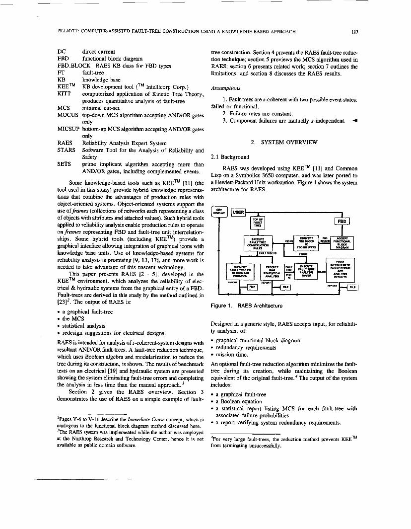
RAES was developed using KEETM [ l l ] and Common Lisp on a Symbolics 3650 computer, and was later ported to a Hewlett-Packard Unix workstation. Figure 1 shows the system architecture for RAES .
I
Figure 1. RAES Architecture
Designed in a generic style, RAES accepts input, for reliabili- ty analysis, of:
graphical functional block diagram redundancy requirements mission time.
An optional fault-tree reduction algorithm minimizes the fault- tree during its creation, while maintaining the Boolean equivalent of the original fault-tree. The output of the system includes:
a graphical fault-tree a Boolean equation a statistical report listing MCS for each fault-tree with
a report verifying system redundancy requirements. associated failure probabilities
4 ~ o r very large fault-trees, the reduction method prevents K E E ~ ~ from terminating unsuccessfully.

114
For electrical system designs, recommended design im- provements to increase system reliability are produced in a report.
2.2 Knowledge Base Design
The RAES KB is divided into sections for:
the FBD specifications the fault-tree construction rules the reliability analysis rules the fault-tree qualitative and quantitative analysis results.
Figure 1 illustrates the sections of the RAES KB and their in- terrelationships. Frames are used in RAES KB to represent FBD and fault-trees as collections of object classes with attributes (slots), and attached values. Class hierarchies enable subclasses to assume properties & values of their respective superclass. During FBD entry, frames representing component hierarchies are formed. Figure 2 shows a sample RAES component KB.
General.Control.Unl <General.Control.Unit 1 General.Control.Unit2
LMC.AC.Bus7
LMC.DC.Busl4
LMC.DC.BuSl5
Main.AC.Bus5 Maii.AC.Bus6
FEDBLOCK K- Main.AC.Bus < Main.DC.Busl2 Main.DC.Bucl3
\\\' Main.DC.Bus <
IEEE TRANSACTIONS ON RELIABILITY, VOL. 43, NO. 1 , 1994 MARCH
\ Main.Generator- Mah.Generator4
RAT.Generator - RAT.Generator.3
Figure 2. RAES FED Component Hierarchy
Each subclass (eg, Main.AC.bus) of FBD.BLOCK inherits the following attributes:
Description - Description of component Equipment.Identifier - Numeric identifier for block Failure.Rate - Constant failure rate for exponential failure
Name - Alphanumeric text for block Power.From - Components with arrows pointing to this unit Power.To - Components being pointed to by arrows from this
distribution
unit.
The values for these attributes are defined specifically for each subclass of FBD.BLOCK. The last 3 attribute values are assign- ed to FBD units when created graphically as members of these subclasses (eg, Main. AC .Bud).
The RAES fault-tree knowledge base is subdivided into gates and basic events. Fault-tree gate attributes include:
Top.Connector - AND or OR gate for which this unit is in-
Type - AND or OR Input.Events - Set of gates and/or basic events.
Fault-tree basic-event attributes are:
Top.Connector - AND or OR gate for which this unit is in-
FBD.Block - Pointer to FBD unit which is represented by
As fault-tree construction rules execute, basic-event units are formed with pointers connecting them to blocks in the FBD. Section 3 illustrates the interplay among RAES KB units.
put event
put event
this basic event.
3. SYSTEM WALK-THROUGH - SIMPLE EXAMPLE
The starting point is the schematic in figure 3 which represents a portion of the fault-tolerant electrical power system of an aircraft [19] used in this study. From this schematic, FBD for 2 failure modes, non flight-critical AC (figure 4) and non flight-critical DC (figure 5), are derived. Although the entire electrical-system schematic could be entered as a FBD, the schematic's components are instead separated into FBD for each failure mode. This division increases computer efficiency dur- ing fault-tree construction. In addition, the manual reliability analysis [19], replicated in this study, used this subdivision technique. For the walk-through, step 1 is the graphical entry of the non flightcritical AC block diagram (figure 4). This block diagram is now stored in the FBD section of the KB.
General Control
Generalor
Load Manage"l Load Management Load Managemen1 Center 1 Center 2 Center 3
Figure 3. Fault-Tolerant Electrical Power System
Upon selection of the fault-tree construction option, the TOP event, block 7 representing AC Bus 1, is chosen from the

ELLIOTT: COMPUTER-ASSISTED FAULT-TREE CONSTRUCTION USING A KNOWLEDGE-BASED APPROACH 115
Figure 4. Non Flight-Critical AC FBD
Figure 5. Non Flight-Critical AC FED
graphical block diagram. This results in the creation of two KB units:
OR gate G1 (designated as the tree's top connector) its input event, basic event 7.
Next the fault-tree construction rules begin operating on these units.
d 4
4 Figure 6. Non Flight-Critical AC Fault Tree
Figure 6 shows the final fault-tree formed by executing these rules. The first rule to fire' searches in the FBD KB for the
'Jargon that means: to cause or to trigger.
block(s) linked to AC Bus 1. This rule creates AND-gate G2 giving it two input events, newly formed basic events 5 & 6, representing AC Bus 9A and AC Bus 9 respectively. To il- lustrate the generic form of the RAES rules, this rule is specified using pseudo code:
If Basic Event X in FT KB has more than 1 FBD units in its FBD Power.From Slot and X's Top.Connector is OR-Gate Y
then 1. Create AND-Gate 2 in FT KB. 2. Add AND-Node 2 as an
Input.Event for OR-Gate Y and add OR-Gate Y as Top.Connector for AND-Gate 2.
3. Create Basic Events for all FBD units in X's Power.From slot and for each unit W do:
a. Add W to AND-Gate Z's
b. Add AND-Gate 2 as W's Input. Event.
Top. Connector.
The variables X, Y, Z are bound to 7, G1, G2 respective- ly during the first rule-firing. The units bound to variable W are basic events 5 & 6. Next OR-gate G2's input event 5 trig- gers a different rule-firing which creates OR-Gate G3 with in- put event 5 . One of G2's Input. Event slot values is changed from basic event 5 to OR-gate G3. Now the first rule fires again with input event 5 matching variable X and OR-gate G3 coinciding with Y. The result of this rule firing is the creation of AND- gate G4 (bound to Z) and its input events, blocks 3 & 6 (bound to W). These recursive rule-firings continue, creating the sub- tree under AND-gate G4. Lastly, input event 6 under AND- gate G2 triggers a similar rule-firing sequence to form the sub- tree under OR node G7 ending with the fault-tree in figure 6. (It is beyond the scope of this paper to present all of the RAES rules. Details regarding the fault-tree construction rules are in
From the various rule-firing priorities available in KEEm [ 1 11, the method which prioritizes rule-firing on the most recent- ly formed KB unit was selected. The numbering of gates in the fault-trees reflects this sequential depth-first creation of KB units. In this manner, subtrees can be reduced using Boolean algebra during the fault-tree construction as shown in section 4. The same rules which formed the AC fault-tree are used to create fault-trees for the DC failure mode. Figure 7 shows the fault-tree generated from the DC FBD in figure 5 . The added complexity of one more redundant path between DC buses 12 & 13 increases the size of the DC fault-tree units to about tri- ple that of the AC tree (from 23 to 58). In both trees, redun- dancy between components causes replicated subtrees. When large fault-tolerant systems with multiple redundancies are analyzed using fault-trees, the fault-trees become very large with many subtree replications. One means of minimizing the size of fault-trees is to use Boolean reduction and module-
~ 5 1 .I

116 IEEE TRANSACTIONS ON RELIABILITY, VOL. 43, NO. 1, 1994 MARCH
Figure 7. Non Flight-Critical DC Fault Tree
identification. These methods are used in RAES and are described in section 4.
4. FAULT-TREE REDUCTION
Nomenclature
1. Module - Subtree in the fault-tree for which a basic event has been expanded.
2. Level - The hierarchical location of a node in the fault- tree, beginning with 1 for the top-level gate, 2 for the top-level
A fault-tree reduction algorithm is included in RAES to reduce computation time for fault-tree construction and for MSC calculation. Two methods are used in the reduction:
Pointers linking modules to duplicate subtrees in levels 1 -
Reduction of gates in subtrees by applying, to all subtrees,
gate's input events, etc. 4
8 of the tree.
the Boolean-algebra laws of absorption:
X + XY = X and AA = A. 4
Identification of modules with replicated events is beneficial for fault-tree analysis [12, 241. Unlike such techniques which reduce the fault-tree after its construction, RAES reduces the fault-
tree during its generation. A module identification technique for levels 1 - 8 of the fault-tree is combined with Boolean-algebra reduction for subtrees at all levels. The limitation of module iden- tification and pointers to levels 1 - 8 enabled lower-level subtrees to benefit from Boolean algebra reduction. In this way, the modules used as pointer links are reduced to a manageable size for quantification. Execution time for fault-tree construction was optimum with pointers on levels 1 - 8 for the fault-trees reduced in this study. A formal proof of this reduction technique and results of its application to large fault-trees is in [5 ] .
Figure 8 shows the reduced version of the fault-tree in figure 6. The reduction algorithm searches, during fault-tree rule execution, for possible elimination of subtrees using the Boolean-algebra principle of absorption.
1. The subtree under OR-gate G3 is formed with no reduction.
2. As basic event 6 under OR node G7 is formed, the reduc- tion algorithm searches under OR-gate G3 for possible subtree candidates for elimination. OR-gate G6 is a candidate for ab- sorption and so it is deleted before the addition of OR-gate G9 with input events 2 & 4.
3. Prior to adding OR-gate G10, the rules detect that sub- tree OR-node G3 absorbs the input events to OR-gate G10 so it is not added. 4
The module identification technique is not used for this small fault- tree. See [3,5] for examples of module identification using RAES.
'

ELLIOTT: COMPUTER-ASSISTED FAULT-TREE CONSTRUCTION USING A KNOWLEDGE-BASED APPROACH 117
automate the fault-tree construction process. STARS (Software Tool for the Analysis of Reliability and Safety) [17] is an ex- pert system which analyzes system safety & reliability, including hazard identification, qualitative analysis, and fault-tree con- struction & evaluation. STARS uses backward chaining (goal driven) reasoning to construct a fault-tree, sometimes eliciting information interactively from the user, in contrast to RAES which uses a forward chaining (inductive) process. The STARS production rules are more complicated than RAES due to in- cluding process variables and macro fault-trees. Unlike RAES, STARS does not use the system description to recommend reliability improvements.
7. LIMITATIONS Figure 8. Reduced Non Flight-Critical AC Fault Tree
5 . MINIMAL CUT-SET ALGORITHM
MCS algorithms have been successfully implemented in computer programs such as MOCUS [SI, SETS [25], and MIC- SUP [16]. The widely used MOCUS [SI algorithm stores the Boolean Indicated Cut Sets (BICS) in a matrix and then uses a pattern-matching technique to determine the MCS.
Of these [8, 16, 251 MCS algorithms, MICSUP [16] is closest to the RAES algorithm. Both MICSUP & RAES use the bottom-up approach to compute MCS, using depth-first search to calculate minimal BICS for each intermediate gate. Unlike MICSUP, RAES uses recursion with a list-processing language and a hash table for intermediate cut-set storage. Fault- tree reduction prior to MCS computation reduces computer time & space. Furthermore, by using a hash table for storage of MCS, the amount of dynamic storage needed is for MCS of the current fault-tree only. This is an improvement over MIC- SUP which needs storage for an array dimensioned to the max- imum allowable number of MCS.
The RAES recursive algorithm to compute MCS is in [ 5 ] . The MCS are stored in the RAES KB for further statistical analysis. The exponential distribution provides the probabilities of failure for the blocks in each MCS.
Notation
x constant failure rate represented as N . 10 -6 , N is an integer
Xi block failure rate t mission time 5 failure-probability for MCS j Ft system failure-probability: Cy= 4. Other, standard notation is given in “Information for Readers & Authors” at the rear of each issue.
6. RELATED WORK
Some knowledge-based systems have been developed to aid reliability analysis [9, 131. However, these systems do not
The fault-tree construction methodology in this paper is limited to 2-state s-coherent fault-trees. Therefore, it can not model complex systems with control loops as found in chemical processing [ 141. All MCS are calculated instead of allowing for a maximum cut-set size or a limit on failure probabilities. In addition, deriving FBD directly from computer-aided design (CAD) data would enhance the system’s utility. (Previous ex- periments with CAD data as input to RAES have been at- tempted with preliminary success.) RAES reliability analysis would be enhanced by adding a common-cause analysis [23]. The redundancy check rules, which analyze the MCS, could be modified for this purpose.
8. RAES RESULTS
RAES was tested by analyzing the reliability of two air- craft (F-18) subsystems:
a fault-tolerant electrical power system a hydraulic system.
For the electrical power system, 4 failure modes were considered:
non flight-critical AC mode non flight-critical DC mode mission-critical DC mode flight-critical DC mode.
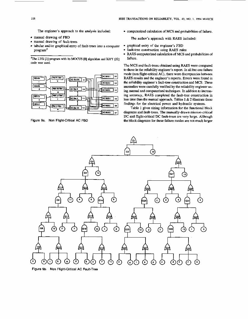
Figure 9 shows the non flight-critical AC FBD and its correspon- ding fault-tree. The hydraulic system [4] has 1 failure mode - loss of power to the aircraft hydraulic system. The FBD and fault-trees used to test RAES were obtained from manual reliability analysis reports on a fault tolerant electrical power system [19] and hydraulic system designs for an aircraft. Throughout this study, the expert reliability engineer who com- pleted these manual studies provided the author (the knowledge engineer) with reliability analysis knowledge and verified RAES results.
118 IEEE TRANSACTIONS ON RELIABILITY, VOL. 43, NO. 1, 1994 MARCH
The engineer’s approach to the analysis included: computerized calculation of MCS and probabilities of failure.
manual drawing of FBD manual drawing of fault-trees tabular and/or graphical entry of fault-trees into a computer program‘
%he LTG [l] program with its MOCUS [8] algorithm and KITT [22] code was used.
Figure 9a. Non Flight-Critical AC FBD
The author’s approach with RAES included:
graphical entry of the engineer’s FBD fault-tree construction using RAES rules RAES computerized calculation of MCS and probabilities of failure.
The MCS and fault-trees obtained using RAES were compared to those in the reliability engineer’s report. In all but one failure mode (non flight-critical AC), there were discrepancies between RAES results and the engineer’s reports. Errors were found in the reliability engineer’s fault-tree construction and MCS. These anomalies were carefully verified by the reliability engineer us- ing manual and computerized techniques. In addition to increas- ing accuracy, RAES completed the fault-tree construction in less time than the manual approach. Tables 1 & 2 illustrate these findings for the electrical power and hydraulic systems.
Table 1 gives sizing information for the functional block diagrams and fault-trees. The manually-drawn mission-critical DC and flight-critical DC fault-trees are very large. Although the block diagrams for these failure modes are not much larger
I I
I
Figure 9b. Non Flight-Critical AC Fault-Tree

ELLIOTT: COMPUTER-ASSISTED FAULT-TREE CONSTRUCTION USING A KNOWLEDGE-BASED APPROACH 119
TABLE 1 FBD and Fault-Tree Sizes
with individual expertise. They are used to show the differences between manual fault-tree construction and the RAES approach.
Fault-Tree Fault-tree
Failure Modes Blocks Connectors Non-Reduced Reduced FBD FBD Manual, RAES,
Non Flight-Critical AC 18 24 80 39 Non Flight-Critical DC 20 26 330 146 Mission-Critical DC 22 25 1010 21 1 Flight-Critical DC 27 45 3575 387 Hydraulic 41 45 267 141
than the others, their corresponding fault-trees are much big- ger. This is due to the increase in redundancy in these failure modes and to the use of multiple failures as the TOP event. Although the hydraulic system block diagram (41 blocks) is larger than the flight-critical DC (27 blocks), its fault-tree is considerably smaller - 267 for hydraulic vs 3575 for DC. This happened because the hydraulic system had fewer redundant connectors. In all cases, the RAES reduced trees are smaller.
TABLE 2 FBD and Fault-tree Manual Versus RAES Times
[All times are in hours]
Manual Approach RAES Approach
Fault-tree FBD Failure Fault-tree Graphical Graphical Fault-tree Mode Manual Entry Entry Construction Errors/MCS
NFC AC 0.7 0.3 0.18 0.05 0176 NFC DC 2.8 1.4 0.20 0.17 11110 MC DC 8.4 4.2 0.20 0.33 141140 FC DC 30. 15. 0.30 0.50 21480 HYD 2.2 1 . 1 0.36 0.75 301350
Table 2 illustrates the time differentials for phases of the manual vs RAES approach and the errors found in the MCS. Each approach in this table begins with a FBD and ends with a fault-tree ready for automated MCS calculation. Presenting the times in this fashion enables direct comparison of the duration of fault-tree construction in the several approaches. These times were derived from estimates of the reliability engineer and from the author’s experiments.
The manual fault-tree drawing is estimated at 30 sec/node including drawing and analytic reasoning. Graphical or tabular entry of fault-- into reliability analysis programs is estimated at 15 sec/node. (The reliability engineer’s programs for this pur- pose enabled pointers for replicated subtrees, not reflected in our estimates). Graphical entry of functional block diagrams into RAE# is estimated at 15 sechlock and 15 sec/connector for block diagrams. The RAES fault-tree construction times were based on averages of several executions. These times varied due to the LISP language’s periodic garbage collection [6] to reclaim memory. These values are subjective and would, or course, vary
Figure 10. Rewired Non-flight Critical AC Functional Block Diagram
The improvements of RAES over manual times is most evi- dent in larger fault-trees. For example, the total estimate for non flight-critical AC mode in the manual approach, with 80 fault- tree nodes, is 60 minutes vs 14 minutes for RAES (a difference of only 46 minutes). In contrast with a larger fault-tree, the total time for flightcritical DC in the manual approach, with 3575 fault-tree nodes, is about 45 hours vs 0.8 hours for RAES (a dif- ference of 44.2 hours). The reason for such a wide differential is that the manual approach requires the lengthy process of draw- ing and entering fault-trees vs block diagram entry in RAES. As the ratio of fault-tree nodes to blocks increases, this gap between the manual vs RAES approach widens. To illustrate this point, consider that using the manual approach for the flightcritical DC mode required manual drawing and graphical entry of 3575 fault- tree nodes. Using RAES, this same mode required graphical entry of only 27 blocks and 45 connectors.
Errors found in the MCS derived using the engineer’s ap- proach were due to fault-tree omissions and transcription errors. For large fault-trees of the mission-critical DC and flight-critical DC modes, the engineer separated them into subtrees, solved each one separately for MCS, and then conjoined the cut-sets for the final solution. Errors occurred in this process, in the transcription andor combination. Many errors were found in the hydraulic system (30 out of 350 cut sets); they were due to a fault-tree omission of several nodes during manual drawing.
Both the redundancy check and rewiring rules incorporated into RAES were derived from the reliability engineer who par- ticipated in this study. The redundancy check rules examine the MCS of the designated fault-tree to determine if the redundancy requirement has been met. These rules were able to verify the redundancy requirements for all 4 failure modes of the fault- tolerant electrical power system. The rewiring rules analyze the connections between the AC & DC buses, and check for anomalies (in these connections) which could result in compo- nent failures affecting the system reliability. Rewiring sugges- tions made by these rules for the non flightcritical AC mode and the non flightcritical DC mode matched the reliability engineer’s manual recommendations [19]. An example of a rewiring-suggestion is shown in the non flight-critical AC FBD
120 IEEE TRANSACTIONS ON RELIABILITY, VOL. 43, NO. 1, 1994 MARCH
in figure 9. In the previous design for this AC failure mode (figure 3), if both AC buses 9 & 8A fail, then all 3 load- management AC buses 1 - 3 are without power. In the rewired version, if AC buses 9 & 8A fail, only 1 load-management AC bus is without power. Now no 2 load-management AC buses have power supplied to it from the same 2 main AC buses.
The purpose of implementing these reliability rules was to test whether a knowledge-based system could reason sym- bolically about the reliability analysis. Future knowledge-based system developers for reliability analysis could exploit this technological capability by encoding reliability analysis rules for other scenarios.
ACKNOWLEDGMENT
I am pleased to thank Abas Ghasemkhani of the Northrop Aircraft Division for his help in establishing the reliability engineering requirements for the system, and for his feedback on the user interface. The editor and referees provided much valued advice in revisions of this paper.
REFERENCES
L. Bass, H.W. Wynholds, W.R. Porterfield, “Fault-tree graphics”, in
M.S. Elliott, “Knowledge-based systems for reliability analysis in con- current design”, Proc. IJCAZ89 Concurrent Engineering Design WonEshop, 1989. M.S. Elliott, “Knowledge-based systems for reliability analysis”, Proc. Ann. Reliability & Maintainability Symp, 1990, pp 481-489. M.S. Elliott, “Reliability analysis expert system in concurrent engineer- ing”, Proc. 2“ Nafl Symp. Concurrent Engineering, 1990, pp 595-609. M.S. Elliott, “Computer-assisted fault-tree construction using a knowledge-based approach’ ’ , TR92-98,1992; University of California, Irvine. M. W. Firebaugh, Arrificial Intelligence Knowledge-Based Approach, 1988; Boyd & Fraser. J.B. Fussell, “Computer aided fault-tree construction for electrical systems” in [26, pp 37-56]. J.B. Fussell, E.B. Henry, N.H. Marshall, “MOCUS - A computer pro- gram to obtain minimal sets from fault-trees”, ANCR-1156,1974; Aerojet Nuclear Co. S. Gambba, E. Guagnini, P. Mussio, “An expert system for fault-tree construction”, Proc. Ann. Reliability & Maintainability Symp, 1985, pp
S. Harbater, W.C. Tonnelli, A.L. Belski, “Computer-aided reliability diagnostic system”, Proc. Ann. Reliability and Maintainability Symp,
Intellicorp Corp., KEETM Software Development System User’s Manual, 3.0-v-1 edition, 1986; Intellicorp Corp. T. Kohda, E.J. Henley, K. Inoue, “ F i g d e s in fault-trees”, IEEE Trans. Reliability, vol 38, 1989 Jun. pp 165-176.
[26, pp 913-9271.
82-88.
1988, pp 8-9.
[13] K.M. Kmwinski, R. Smurthwaite, “Automated fault-tree analysis via AI/ES”, Proc. Ann. Reliability & Maintainability Symp, 1988, pp
[14] S.A. Lapp, G.J. Powers, “Computer-aided synthesis of fault-trees”, IEEE Trans. Reliability, vol R-26, 1977 Apr, pp 2-13.
[I51 W.S. Lee et al., “Fault-tree analysis, methods, and applications - A review”, IEEE Trans. Reliability, vol R-34, 1985 Aug, pp 194-203.
[16] P.K. Pande, M.E. Spector, P. Chatterjee, “Computerized fault-tree analysis TREEL and MICSUP”, ORC 75-3, 1975; Operation Research Center, university of California, Berkeley.
[17] A. Poucet, “Stars: Knowledge based tools for safety and reliability analysis”, Reliability and System Safety, vol 30, 1990, pp 379-397.
[18] S.L. Salem, G.E. Apostolakis, D. Okrent, “A new methodology for the
33 1-335.
computer-aided construction of fault-trees”, J. Nuclear Energy, vol4, 1977, pp 417-433. M. Shah, A. Ghasemkhani, “ P r e l i i redundancy/reliability analysis fault tolerant electrical power system (FTEPS)”, Northrop FSCM No. 76823, 1987; Northrop Aircraft Division. J.R. Taylor, “An algorithm for fault-tree construction”, IEEE Trans. Reliability, vol R-31, 1982 Jun, pp 137-146. N.H. Ulerich, G.J. Powers, “On-line hazard aversion and fault diagnosis in chemical processes: The digraph and fault-tree method”, IEEE Trans. Reliability, vol 37, 1988 Jun, pp 171-177. W.E. Vesely, “Reliability and fault-tree applications at the NRTS”, Proc. Ann. Reliability & Maintainability Symp, 1970, pp 472-480. W.E. Vesely etal, Fault-Tree Handbook, 1981; US Nuclear Regulatory Commission. J. Wilson, “Modularizing and minimizing fault-trees”, IEEE Trans. Reliability, vol R-34, 1985 Oct, pp 320-322. R.B. Worrell, “Using the set equation transformation system in fault- tree analysis”, in [26, pp 165-1851. R.E. Barlow, J.B. Fussell, N.D. Singpurwalla (Eds), Reliability and Fault- Tree Analysis, 1975; SIAM.
AUTHOR
Margaret S. Elliott; Dept. of Information & Computer Science; University of California, Irvine, California 92717 USA. Internet (e-mail): [email protected]
M. Elliott (M’86, S90) was born in Pennsylvania on 1949 November 8. She is attending the University of California, Irvine as a PhD candidate in the Dept. of Information and Computer Science. Her research interests include artificial intelligence techniques applied to reliability analysis, soffware usability, computer integrated manufacturing, and the social implications of computing. From 1985 to 1990, she worked as a research engineer at Northrop Research and Technology Center; and from 1982 to 1985, as a supervisor of software development at Rockwell International. From 1978 to 1982, she was employed by other aerospace and software development firms. She has published several technical papers and is a member of AAAI, ACM, and IEEE. She received a BS (1971) in Education from Miersville University, an MS (1976) in Muca- tion from West Chester University, an MS (1979) in Computer Science from Villanova University, and an MS (1993) in Information & Computer Science from University of California, Irvine.
Manuscript TR90-179 received 1990 September 20; revised 1992 September 25; revised 1993 September 20; revised 1994 January 10.
IEEE Log Number 00272 4TRD