computer integrated manufacturing - sasurie college of ... sem 7/me 240… · unit – i - computer...
TRANSCRIPT
A Course Material on
Computer Integrated Manufacturing
By
Mr. T.Manokaran ME,MBA
ASSISTANT PROFESSOR
DEPARTMENT OF MECHANICAL ENGINEERING
SASURIE COLLEGE OF ENGINEERING
VIJAYAMANGALAM – 638 056

QUALITY CERTIFICATE
This is to certify that the e-course material
Subject Code : ME 2402
Subject : Computer Integrated Manufacturing.
Class : IV Year Mechanical Engineering.
being prepared by me and it meets the knowledge requirement of the university curriculum.
Signature of the Author
Name:T.Manokaran ME,MBA
Designation: Assistant Professor.
This is to certify that the course material being prepared by Mr.T.Manokaran is of adequatequality. He has referred more than five books among them minimum one is from aborad author.
Signature of HD
Name: E.R.Sivakumar ME, (Ph.D)
SEAL

ME2402 COMPUTER INTEGRATED MANUFACTURING L T P C 3 0 0 3
OBJECTIVE: This course will enable the student To gain knowledge about the basic fundamental of CAD. To gain knowledge on how computers are integrated at various levels of planning
and manufacturing understand computer aided planning and control and computermonitoring.
UNIT I COMPUTER AIDED DESIGN 9Concept of CAD as drafting and designing facility, desirable features of CAD package,drawing features in CAD – Scaling, rotation, translation, editing, dimensioning, labeling,Zoom, pan, redraw and regenerate, typical CAD command structure, wire frame modeling,surface modeling and solid modeling (concepts only) in relation to popular CAD packages.
UNIT II COMPONENTS OF CIM 9CIM as a concept and a technology, CASA/Sme model of CIM, CIM II, benefits of CIM,communication matrix in CIM, fundamentals of computer communication in CIM – CIM datatransmission methods – seriel, parallel, asynchronous, synchronous, modulation,demodulation, simplex and duplex. Types of communication in CIM – point to point(PTP), star and multiplexing. Computer networking in CIM – the seven layer OSI model,
LAN model, MAP model, network topologies – star, ring and bus, advantages ofnetworks in CIM
UNIT III GROUP TECHNOLOGY AND COMPUTER AIDED PROCESSPLANNING 9
History Of Group Technology – role of G.T in CAD/CAM Integration – part families-classification and coding – DCLASS and MCLASS and OPTIZ coding systems – facilitydesign using G.T – benefits of G.T – cellular manufacturing.Process planning - role of processplanning in CAD/CAM Integration – approaches to computer aided process planning – variantapproach and generative approaches – CAPP and CMPP systems.
UNIT IV SHOP FLOOR CONTROL AND INTRODUCTION TO FMS 9 shopfloor control – phases – factory data collection system – automatic identification methods –Bar code technology – automated data collection system.FMS – components of FMS – types – FMS workstation – material handling and storage system–FMS layout- computer control systems – applications and benefits.
UNIT V COMPUTER AIDED PLANNING AND CONTROL AND COMPUTERMONITORING 9
Production planning and control – cost planning and control – inventory management –material requirements planning (MRP) – shop floor control. Lean and AgileManufacturing. Types of production monitoring systems – structure model of manufacturing –process control and strategies – direct digital control.
TOTAL: 45 PERIODS
TEXT BOOK:
1. Mikell. P. Groover “Automation, Production Systems and Computer IntegratedManufacturing”, Pearson Education 2001.
REFERENCES:
1. Mikell. P. Groover and Emory Zimmers Jr.,“CAD/CAM”, Prentice hall of India Pvt.Ltd., 1998.
2. James A. Regh and Henry W. Kreabber, “Computer Integrated Manufacturing”,Pearson Education second edition, 2005.
3. Chris McMahon and Jimmie Browne, “CAD CAM Principles, Practice andManufacturing Management”, Pearson Education second edition, 2005.
4. Ranky, Paul G., “Computer Integrated Manufacturing”, Prentice hall of India Pvt. Ltd.,2005.
5. Yorem Koren, “ Computer Integrated Manufacturing”, McGraw Hill, 2005.6. P N Rao, “ CAD/CAM Principles and Applications”, TMH Publications, 2007.
CONTENTS
Chapter Topic Page no
UNIT – I - COMPUTER AIDED DESIGN
1.1. Concept of CAD 2
1.2. CAD system - Hardware & Software. 3
1.3. Features of CAD packages. 4
1.3.1. Graphic Entities. 5
1.3.2. Graphic Utilities. 5
1.3.3. CAD – Drawing Editing Commands. 5
1.3.4. Graphic Transformations. 7
1.4. Geometric Modeling 8
1.4.1. Wireframe Modeling 9
1.4.2. Surface Modeling 10
1.4.3. Solid Modeling 10
1.4.4. Solid Modeling Vs Surface Modeling. 11

1.5. Advantages and Applications of CAD packages 12.
UNIT – II - COMPONENTS OF CIM
2.1. Concept or Technology of CIM. 14
2.2. CIM System – Hardware & Software 15
2.3. CIM – Wheel Elements. 16
2.4. Computer Communication in CIM 17
2.5. Communication Network in CIM. 17
2.5.1. Types of Communication Network in CIM. 18
2.6. ISO / OSI model – 7 layers of OSI model. 19
2.7. LAN Components. 20
2.8. LAN Topologies. 20
UNIT – III - GROUP TECHNOLOGY ANDCOMPUTER AIDED PROCESS PLANNING
3.1. Concept of Group Technology. 20
3.2. Benefits of G.T. in CIM. 21
3.3. Methods for Part Family. 22
3.4. Cellular Manufacturing. 23
3.5. Process Planning. 24
3.5.1. Computer Aided Process Planning. 24
3.5.2. Variant or Retrieval approach. 25
3.5.3. Generative approach. 26
UNIT – IV - SHOP FLOOR CONTROL AND
INTRODUCTION TO FMS
4.1. Concept of SFC. 28
4.2. Functions of SFC 29

4.2. Functions of shop floor control – SFC 29
4.3. Factory Data Collection System 30
4.4. Automatic identification methods 32
4.5. Barcode Technology in automatic data collection system 33
4.6. Flexible manufacturing system – FMS 35
4.6.1. Components of FMS systems; 35
4.6.2. Benefits of FMS 36
4.6.3. Types of FMS 37
UNIT – V - COMPUTER AIDED PROCESS PLANNING AND
CONTROL AND COMPUTER MONITORING.
5.1. Production Planning and control 39
5.2. Inventory management in CIM 42
5.3. Material requirements planning (MRP) in CIM 43
5.4. Shop Floor Control. 46
5.5. Agile and Lean manufacturing in CIM 48
5.6. Direct digital control (DDC) 50
6 Question Bank. 52

ME 2402 COMPUTER INTEGRATED MANUFACTURING
[Type text] SCE 2015-16 MECHANICAL ENGINEERING
ME2402 COMPUTER INTEGRATED MANUFACTURING L T P C 3 0 0 3
UNIT I COMPUTER AIDED DESIGN 9Concept of CAD as drafting and designing facility, desirable features of CAD package,drawing features in CAD – Scaling, rotation, translation, editing, dimensioning, labeling,Zoom, pan, redraw and regenerate, typical CAD command structure, wire frame modeling,surface modeling and solid modeling (concepts only) in relation to popular CADpackages.
UNIT II COMPONENTS OF CIM 9CIM as a concept and a technology, CASA/Sme model of CIM, CIM II, benefits of CIM,communication matrix in CIM, fundamentals of computer communication in CIM – CIMdata transmission methods – seriel, parallel, asynchronous, synchronous, modulation,demodulation, simplex and duplex. Types of communication in CIM – point to point(PTP), star and multiplexing. Computer networking in CIM – the seven layer OSI model,
LAN model, MAP model, network topologies – star, ring and bus, advantages ofnetworks in CIM
UNIT III GROUP TECHNOLOGY AND COMPUTER AIDED PROCESSPLANNING 9History Of Group Technology – role of G.T in CAD/CAM Integration – part families-classification and coding – DCLASS and MCLASS and OPTIZ coding systems – facilitydesign using G.T – benefits of G.T – cellular manufacturing.Process planning - role of process planning in CAD/CAM Integration – approaches tocomputer aided process planning – variant approach and generative approaches – CAPPand CMPP systems.
UNIT IV SHOP FLOOR CONTROL AND INTRODUCTION TO FMS 9shop floor control – phases – factory data collection system – automatic identificationmethods – Bar code technology – automated data collection system.FMS – components of FMS – types – FMS workstation – material handling and storagesystem –FMS layout- computer control systems – applications and benefits.
UNIT V COMPUTER AIDED PLANNING AND CONTROL AND COMPUTERMONITORING 9
Production planning and control – cost planning and control – inventory management –material requirements planning (MRP) – shop floor control. Lean and AgileManufacturing. Types of production monitoring systems – structure model ofmanufacturing – process control and strategies – direct digital control.
TEXT BOOK: TOTAL: 45 PERIODS
1. Mikell. P. Groover “Automation, Production Systems and Computer IntegratedManufacturing”, Pearson Education 2001.
SCE 2015-16 MECHANICAL ENGINEERING

ME 2402 COMPUTER INTEGRATED MANUFACTURING
[Type text] SCE 2015-16 MECHANICAL ENGINEERING
UNIT – I
COMPUTER AIDED DESIGN
Pre Requisite Discussions:
The 21st century business environment can be characterized by expanding globalcompetition and produce of increasing variety and lower demand.
CAD / CAM / CIM are considered as a key component strategy for manufacturingenterprises to achieve this. During the last twenty years the CIM technology is undergoneconsiderable changes.
The CAD /CAM technology has become more sophisticated and seamlessintegrations between different applications is no longer an issue. The intranet and wide webcan now help to achieve significant time compression in product developments.
Concept:The display of the drawing or the geometric models of the component in CAD uses
the technology of computer graphics.The techniques of raster technology scan conversion, clipping, removal of hidden
lines and hidden surfaces, coloring, and texture are briefly dealt in this unit.
1.1. Concept of CAD;
Computer-aided design (CAD) is the use of computer systems to assist in thecreation, modification, analysis, or optimization of a design. CAD software is used toincrease the productivity of the designer, improve the quality of design, improvecommunications through documentation, and to create a database for manufacturing. CADoutput is often in the form of electronic files for print, machining, or other manufacturingoperations.
Computer-aided design is used in many fields. Its use in designing electronic systemsis known as Electronic Design Automation, or EDA. In mechanical design it is known asMechanical Design Automation (MDA) or computer-aided drafting (CAD), whichincludes the process of creating a technical drawing with the use of computer software.
CAD software for mechanical design uses either vector-based graphics to depict theobjects of traditional drafting, or may also produce raster graphics showing the overallappearance of designed objects. However, it involves more than just shapes. As in themanual drafting of technical and engineering drawings, the output of CAD must conveyinformation, such as materials, processes, dimensions, and tolerances, according toapplication-specific conventions. CAD may be used to design curves and figures in two-dimensional (2D) space; or curves, surfaces, and solids in three-dimensional (3D) space.
Computer-aided manufacturing (CAM) is the use of computer software to controlmachine tools and related machinery in the manufacturing of work pieces. This is not theonly definition for CAM, but it is the most common; CAM may also refer to the use of acomputer to assist in all operations of a manufacturing plant, including planning,management, transportation and storage.
Its primary purpose is to create a faster production process and components andtooling with more precise dimensions and material consistency, which in some cases, uses

ME 2402 COMPUTER INTEGRATED MANUFACTURING
[Type text] SCE 2015-16 MECHANICAL ENGINEERING
only the required amount of raw material (thus minimizing waste), while simultaneouslyreducing energy consumption.
CAM is now a system used in schools and lower educational purposes. CAM is asubsequent computer-aided process after computer-aided design (CAD) and sometimescomputer-aided engineering (CAE), as the model generated in CAD and verified in CAE canbe input into CAM software, which then controls the machine tool.
CAD, CAM and CIM ;
CAD/CAM involves the use of computers to make Design and Manufacturing moreprofitable.
Parts of CIM use CAD/CAM techniques and products to try and make the factoryfully connected using computers.
The essential difference is CAD/CAM provides the tools, CIM is the philosophywhich is used when organizing the computers, programs, etc. and all the informationthat flows between them. CIM focuses on connecting the various CAD/CAMmodules.
1.2. CAD system;
The cad system consists of two basic components; they are
Computer Hardware;- It consists of graphic workstations,- Graphic input devices like keyboard, mouse etc.,- Graphic output devices like printer and plotters.
Computer Software;- It consists of operating system for basic operations,- Software package used for geometric modeling,- Application software for design, analysis and synthesis.
Elements of CAD; (or) Various phases of CAD;
The design process in a CAD system consists of 4 stages / phases, they are;
Geometric modeling, Design analysis and optimization, Design review and evaluation, Documentation and drafting.
1.3...Features of CAD Packages;

ME 2402 COMPUTER INTEGRATED MANUFACTURING
[Type text] SCE 2015-16 MECHANICAL ENGINEERING
Computer-aided design (CAD) is the use of computer systems to assist in thecreation, modification, analysis, or optimization of a design. CAD software is used toincrease the productivity of the designer, improve the quality of design, improvecommunications through documentation, and to create a database for manufacturing. CADoutput is often in the form of electronic files for print, machining, or other manufacturingoperations.
Computer-aided design is used in many fields. Its use in designing electronic systemsis known as Electronic Design Automation, or EDA. In mechanical design it is known asMechanical Design Automation (MDA) or computer-aided drafting (CAD), which includesthe process of creating a technical drawing with the use of computer software.
CAD software for mechanical design uses either vector-based graphics to depict theobjects of traditional drafting, or may also produce raster graphics showing the overallappearance of designed objects. However, it involves more than just shapes. As in themanual drafting of technical and engineering drawings, the output of CAD must conveyinformation, such as materials, processes, dimensions, and tolerances, according toapplication-specific conventions. CAD may be used to design curves and figures in two-dimensional (2D) space; or curves, surfaces, and solids in three-dimensional (3D) space.
CAD may be used to design curves and figures in two-dimensional (2D) space; orcurves, surfaces, and solids in three-dimensional (3D) space.
CAD is an important industrial art extensively used in many applications, includingautomotive, shipbuilding, and aerospace industries, industrial and architecturaldesign, prosthetics, and many more. CAD is also widely used to produce computeranimation for special effects in movies, advertising and technical manuals, oftencalled DCC digital content creation. The modern ubiquity and power of computersmeans that even perfume bottles and shampoo dispensers are designed usingtechniques unheard of by engineers of the 1960s. Because of its enormous economicimportance, CAD has been a major driving force for research in computationalgeometry, computer graphics (both hardware and software), and discrete differentialgeometry.
The design of geometric models for object shapes, in particular, is occasionally calledcomputer-aided geometric design (CAGD).
Computer-assisted surgery (CAS) Computer-aided surgical simulation (CASS) Computational fluid dynamics (CFD) Component information system (CIS) Computer-integrated manufacturing (CIM) Computer Numerical Controlled (CNC)
1.3.1.. Drawing entities;A drawing is created using a no. of entities. A large no. of options are
provided to draw the entities depending upon the requirements. Common entities are;

ME 2402 COMPUTER INTEGRATED MANUFACTURING
[Type text] SCE 2015-16 MECHANICAL ENGINEERING
Point, * Line, * Arc, * Ellipse, Circle, *Polygon, *Spline, *Rectangle, etc.,
1.3.2. Drawing Utilities;
Drawing utilities include several functions to have the creation and storage ofdrawings. Common utilities are;
*Screen size, * Line type, * Scaling * Layers,
*Grid, *Snap,, *Units, , *file utilities, etc.,
1.3.3.. Editing commands in CAD;
It is necessary to make the corrections and alterations to the entities of adrawing. Editing commands are used for this process.
A few editing commands are listed below,
*Erase, *Move, *Array, *Fillet, * Chamfer*Mirror *Rotate, *Trim, *Copy *Scale, etc.,
Various Edit and Inquiry commands in CAD;
Editing an entity or group of entities in Autocad requires the entity or the group tobe selected. There are three ways of doing this :1) Autocad can be set to allow the user to select the objects first, and then accept commandsto process them. This is called noun/verb selection. This mode of operation can beenabled/disabled using the DDSELECT command which opens up a dialogue box.2) The commands can be given first, and the objects can be specified when the user isprompted for them.3) The SELECT command can be used to select a specific selection set, which can bereferred to in subsequent editing operations.
Editing with grips :Selected objects can be edited by manipulating grips that appear on the selected entity. TheGrips mode can be enabled with the DDGRIPS command which opens up a dialogue box.The editing operations possible using grips are :
Stretch, Move, Rotate, Scale and Mirror
1. Erasing unwanted objects and retrieving accidentally removed ones :The ERASE command permanently removes specified objects. To erase only the drawnobject, enter "L" at the 'select oblects' prompt.
2. The OOPS command restores only the most recently erased objects.3. Copying and Moving :
The commands available are :MOVE, COPY, ROTATE, SCALE, MIRROR, STRETCH and ARRAYThe MOVE and COPY commands are for recreating the object at another place.

ME 2402 COMPUTER INTEGRATED MANUFACTURING
[Type text] SCE 2015-16 MECHANICAL ENGINEERING
The COPY command retains a copy in the original place while the MOVE command doesnot.
4. The SCALE command allows the size of objects to be changed. It scales theobject about a reference point, by expanding/shrinking it equally in all directions.SCALE can be used to rescale an entire drawing in one go.
5. The ARRAY command creates multiple copies of entities in a rectangular or polarpattern. To change the orientation of the array, use SNAP Rotate command orSNAPANG system variable.
6. Changes, Cuts and Constructions : These commands allow you to changeproperties of objects (like color, layer,etc.) and modify objects by trimming/extending their ends, and cutting sections out of them. They can also be used todraw fillet arcs, chamfer lines, parallel lines, offset curves, and construction markers.
The available commands are :
CHANGE, DDEDIT, BREAK, TRIM, EXTEND, FILLET, CHAMFER, OFFSET, DIVIDE,and MEASURE
The CHANGE command is used to change the following :color, elevation, layer, linetype, thickness
Characteristics other than the above can also be changed by specifying a pointinstead of choosing one of the above properties. Then this "change point" is used to modifythe object depending on whether the object is a line or a circle, etc. The "change point"method works for multiple entities also.
Variations of the CHANGE command are : DDCHPROP and CHPROP
The DDEDIT command allows editing of both text and attribute definitions. Thecommand can be used either in paper space or in model space, whichever is activewhen the command is issued. It cannot be used on text attributes that are part of ablock.
The BREAK command erases part of a line, trace, circle, arc or 2D polyline Theend points of the part are specified by the user.
The TRIM command is used to trim objects such that they end exactly at cuttingedges defined by other intersecting objects.
The EXTEND command is the complement of the TRIM command because it letsyou extend an object till it meets another object.
The FILLET command connects two lines, arcs or circles by means of a smoothlyfitted arc of specified radius.
The CHAMFER command is similar : it trims two intersecting lines a specifieddistance from the intersection and connects the trimmed ends with a new linesegment.

ME 2402 COMPUTER INTEGRATED MANUFACTURING
[Type text] SCE 2015-16 MECHANICAL ENGINEERING
The OFFSET command constructs an entity parallel to the specified one, eitherthrough a given point or at a given distance.
The DIVIDE command lets you divide an entity into several equal-length parts,placing markers along the object at the dividing points.
The MEASURE command is similar to the DIVIDE command : it measures anentity and places markers at specified intervals.
Polyline, Mesh, and Block Editing :
There are two basic commands for this : PEDIT and EXPLODE. PEDIT is used to edit 2Dand 3D polylines, and 3D polygon meshes.The EXPLODE command breaks up a complex entity as follows :A Block or associative Dimension is replaced with copies of simple entities comprising theBlock or Dimension. Polylines are replaced with simple and arcs; 3D polygon meshes with3D faces and polyface meshes with 3D faces, lines and points.
Undoing commands : U command : causes the most recent command to be undone. REDO command : reverses the effect of the most recent U command.
UNDO command : can undo several commands simultaneously. Inquiry commands are commands which allow the user to inquire into locations
and relationships into entities. Inquiry commands available in Autocad are : LIST : lists data for an entity.
DBLIST : lists data for every entity in the drawing. ID : gives co-ordinates of a point specified in the graphics window.
DIST : measures angle and distance between
1.3.4. 2D transformations in CAD;
In computer graphics drawing are created by serious primitives which arerepresented by the coordinates of their end points.
Certain changes in these drawings can be made by performing somemathematical operations on these coordinates. The basic transformations are Scaling,Rotation, translation, etc..,
1.4. Geometric modeling;Geometric modeling involves the use of a CAD system to develop a mathematical
description of the geometry of an object. The mathematical description, called a geometricmodel is contained in computer memory. These operations include creating new geometricmodels from basic building blocks available in the system. Geometric modeling is a branch

ME 2402 COMPUTER INTEGRATED MANUFACTURING
[Type text] SCE 2015-16 MECHANICAL ENGINEERING
of applied mathematics and computational geometry that studies methods and algorithms forthe mathematical description of shapes.
The shapes studied in geometric modeling are mostly two- or three-dimensional,although many of its tools and principles can be applied to sets of any finite dimension.Today most geometric modeling is done with computers and for computer-basedapplications. Two-dimensional models are important in computer typography and technicaldrawing. Three-dimensional models are central to computer-aided design and manufacturing(CAD/CAM), and widely used in many applied technical fields such as civil and mechanicalengineering, architecture, geology and medical image processing.
Geometric models are usually distinguished from procedural and object-orientedmodels, which define the shape implicitly by an opaque algorithm that generates itsappearance. They are also contrasted with digital images and volumetric models whichrepresent the shape as a subset of a fine regular partition of space; and with fractal modelsthat give an infinitely recursive definition of the shape.
However, these distinctions are often blurred: for instance, a digital image can beinterpreted as a collection of colored squares; and geometric shapes such as circles aredefined by implicit mathematical equations. Also, a fractal model yields a parametric orimplicit model when its recursive definition is truncated to a finite depth.
Geometric modeling techniques;These are various types of geometric models used in CAD,
Based on the dimensioning,- Two dimensional modeling,- Three dimensional modeling.
Based on the modeling,- Wire frame modeling,- Surface modeling,- Solid modeling.
2D Vs 3D;2D models are best utilized for design problems, such as flat objects and
layouts of building.
3D models are capable of modeling an object in three dimensional accordingto user instructions.
This is helpful in conceptualizing the object since in true 3D models can bedisplayed in various views and form different angles.
1.4.1. Wire-frame modeling technique in CAD;

ME 2402 COMPUTER INTEGRATED MANUFACTURING
[Type text] SCE 2015-16 MECHANICAL ENGINEERING
A wire-frame model is a visual presentation of a three-dimensional (3D) or physicalobject used in 3D computer graphics. It is created by specifying each edge of the physicalobject where two mathematically continuous smooth surfaces meet, or by connecting anobject's constituent vertices using straight lines or curves. The object is projected onto adisplay screen by drawing lines at the location of each edge. The term wire frame comesfrom designers using metal wire to represent the three-dimensional shape of solid objects.3D wire frame allows to construct and manipulate solids and solid surfaces. The 3D solidmodeling technique efficiently draws higher quality representations of solids than theconventional line drawing.
Using a wire-frame model allows visualization of the underlying design structure of a3D model. Traditional two-dimensional views and drawings can be created by appropriaterotation of the object and selection of hidden line removal via cutting planes. Since wire-frame renderings are relatively simple and fast to calculate, they are often used in caseswhere a high screen frame rate is needed (for instance, when working with a particularlycomplex 3D model, or in real-time systems that model exterior phenomena). When greatergraphical detail is desired, surface textures can be added automatically after completion ofthe initial rendering of the wire frame. This allows the designer to quickly review Chansolids or rotate the object to new desired views without long delays associated with morerealistic rendering.
The wire frame format is also well suited and widely used in programming tool pathsfor direct numerical control (DNC) machine tools. Hand-drawn wire-frame-like illustrationsdate back as far as the Italian Renaissance.[1] Wire-frame models were also used extensivelyin video games to represent 3D objects during the 1980s and early 1990s when properlyfilled 3D objects would have been too complex to calculate and draw with the computers ofthe time. Wire-frame models are also used as the input for computer-aided manufacturing(CAM). There are mainly three types of 3D CAD models. Wire frame is one of them and itis the most abstract and least realistic. Other types of 3D CAD models are surface and solid.This method of modeling consists of only lines, points and curves defining the edges of anobject.
Advantages of Wireframe Modeling; Simple to construct,
Designer needs little training. It needs less memory space,
It takes less manipulation time, It is best suitable for manipulation as orthographic, isometric and perspective
views.B-rep – Boundry representation;
B-rep construction consists of entering all boundary edge for all surfaces.This is similar or copying an engineering drawing into the computer, line by line,

ME 2402 COMPUTER INTEGRATED MANUFACTURING
[Type text] SCE 2015-16 MECHANICAL ENGINEERING
surface by surface, with one important qualification. The lines must be entered andsurfaces oriented in such a way that they create valid volumes.
CSG – Constructive Solid Geometry;
CSG technique uses Boolean combinations or primitives solids to build a part.The Boolean operations are addition (+), subtraction (-), as illustrated in threedimensions.
1.4.2. Surface modeling
Surface modeling is defining an object’s exterior with an infinitesimally thin skin.This skin is created by lofts, sweeps, and NURBS curves - i.e. sculptured surfaces with lotsof curvature. The surfaces are either defined by poles or guide curves. A surface isconsidered a solid only when it is completely enclosed. It is used to make technical surfaces(e.g. air plane wing) or aesthetic surfaces (e.g. car’s hood).
It was developed for the aerospace and automotive industries in the late 70s.Rhinoceros 3D and Alias Studio Tools are examples of a surface modeling programs. It isgenerally considered more difficult than solids modeling, but the models are more robustbecause the programs aren’t generally feature based. Later changes have to modify theexisting geometry as opposed to just editing the original feature, which is more difficult butkeeps the model from collapsing when one feature interferes with another.
1.4.3. Solid modeling technique in CAD
Solid modeling (or modelling) is a consistent set of principles for mathematical andcomputer modeling of three-dimensional solids. Solid modeling is distinguished from relatedareas of geometric modeling and computer graphics by its emphasis on physical fidelity.[1]
Together, the principles of geometric and solid modeling form the foundation of computer-aided design and in general support the creation, exchange, visualization, animation,interrogation, and annotation of digital models of physical objects.
The use of solid modeling techniques allows for the automation of several difficultengineering calculations that are carried out as a part of the design process. Simulation,planning, and verification of processes such as machining and assembly were one of themain catalysts for the development of solid modeling. More recently, the range of supportedmanufacturing applications has been greatly expanded to include sheet metal manufacturing,injection molding, welding, pipe routing etc.
Beyond traditional manufacturing, solid modeling techniques serve as the foundationfor rapid prototyping, digital data archival and reverse engineering by reconstructing solidsfrom sampled points on physical objects, mechanical analysis using finite elements, motionplanning and NC path verification, kinematic and dynamic analysis of mechanisms, and soon.

ME 2402 COMPUTER INTEGRATED MANUFACTURING
[Type text] SCE 2015-16 MECHANICAL ENGINEERING
A central problem in all these applications is the ability to effectively represent andmanipulate three-dimensional geometry in a fashion that is consistent with the physicalbehavior of real artifacts. Solid modeling research and development has effectivelyaddressed many of these issues, and continues to be a central focus of computer-aidedengineering.
Advantages of Solid Modeling; It is complete and unambiguous.
Suitable for automated applications like creating part program without muchhuman involvement.
1.4.4. Solids vs. Surface Modeling;
Computer aided design (CAD) isn’t like a car in that you can use it pretty well evenif you don’t know how it works. It pays to know what happening ‘under the hood’ whenusing CAD. It is important to know about surface and solids modeling because it does affectthe way you model, and it is important to know if you are switching platforms. It is also veryimportant to know about for rapid prototyping.
Surfaces and solids are the underlying math that defines the geometry of the formsyou create. There are three ways to define 3D geometry: solids, surfaces and wireframes.Wireframes don’t play much of a role in CAD, but primarily in digital content creation(DCC) and gaming. The easiest way to understand the difference between surface and solidsmodeling is to think of a water balloon; the water in the balloon would be solids modeling,while the latex skin would be surface modeling. Need more of an explanation? No problem.
Solids modeling;
Solids modeling is defining an object with geometric mass. Solids modelingprograms usually create models by creating a base solid and adding or subtracting from itwith subsequent features. Features such as extrudes, extrude cuts, revolves, radii, chamfers,etc. Examples of solids modeling programs are Solid works, CATIA, and Pro Engineer. Itwas originally developed for machine design, and is used heavily for engineering with largepart assemblies, digital testing and rapid prototyping.
Surface modeling;
Surface modeling is defining an object’s exterior with an infinitesimally thin skin.This skin is created by lofts, sweeps, and NURBS curves - i.e. sculptured surfaces with lotsof curvature. The surfaces are either defined by poles or guide curves. A surface isconsidered a solid only when it is completely enclosed. It is used to make technical surfaces(e.g. air plane wing) or aesthetic surfaces (e.g. car’s hood).
It was developed for the aerospace and automotive industries in the late 70s.Rhinoceros 3D and Alias Studio Tools are examples of a surface modeling programs. It is
ME 2402 COMPUTER INTEGRATED MANUFACTURING
[Type text] SCE 2015-16 MECHANICAL ENGINEERING
generally considered more difficult than solids modeling, but the models are more robustbecause the programs aren’t generally feature based. Later changes have to modify theexisting geometry as opposed to just editing the original feature, which is more difficult butkeeps the model from collapsing when one feature interferes with another.
1.5. Advantages & Applications of CAD; High productivity and reduced lead time, Accuracy in design,
Better central over the complete project process, Modifications in design relatively easy,
Simulations of the computer generated model can reduce or eliminateprototype testing,
Effective creation of manufacturing documentation,
Optimized solution can be received, Better communication and presentations.
Applications CAD software package; Automated industries, Manufacturing companies,
Aerospace designs, Civil engineering plans and Electrical circuits, etc..,
Glossary;
Computer-aided design (CAD) Auto cad – by auto desk is one of the best professional design and drafting programs
on the markets. IRON CAD – 3D CAD software for foundries by nova cast. Solid works – powerful 3D CAD software for mechanical design. Simple windows
interfaces with unique drag and do capabilities help designers and engineers buildassemblies in record time.
Pro E - Highly rated 3D mechanical design suite which assists designers andmanufacturing engineering with product development across all industries.
EDGE CAM – site of CAM software for all your NC program needs such as turning,milling, EDM, free burn and advance surface machining.
UNIT – II
COMPONENTS OF CIM
Pre Requisite Discussions:
Computer Integrated Manufacturing, known as CIM, is the phrase used to describethe complete automation of a manufacturing plant, with all processes functioning undercomputer control and digital information tying them together

ME 2402 COMPUTER INTEGRATED MANUFACTURING
[Type text] SCE 2015-16 MECHANICAL ENGINEERING
The heart of computer integrated manufacturing is CAD/CAM. Computer-aideddesign (CAD) and computer-aided manufacturing (CAM) systems are essential to reducingcycle times in the organization. CAD/CAM is a high technology integrating tool betweendesign and manufacturing. CAD techniques make use of group technology to create similargeometries for quick retrieval.
CAD/CAM integrated systems provide design/drafting, planning and scheduling, andfabrication capabilities. CAD provides the electronic part images, and CAM provides thefacility for tool path cutters to take on the raw piece.
CIM Concept Vs CIM Technology
CIM is both a concept and a technology. For top management, CIM is a concept, a blueprint for success. For middle managers and line managers, CIM is a technology
Concept or Technology
“Some people view CIM as a concept, while others merely as a technology. It isactually both. A good analogy of CIM is man, for what we mean by the word manpresupposes both the mind and the body. Similarly, CIM represents both the concept and thetechnology. The concept leads to the technology which, in turn, broadens the concept.”
The meaning and origin of CIM
The CIM will be used to mean the integration of business, engineering,manufacturing and management information that spans company functions from marketingto product distribution
2.1. CIM – Definition;
CIM is the integration of the total manufacturing enterprise through the use ofintegrated systems and data communication coupled with new managerial philosophiesthat improve organizational and personnel efficiency.
Computer integrated manufacturing is defined as the effective use of computers todesign the products, plan the production ,control the operations and perform the variousbusiness related functions needed in a manufacturing firm.
Objective of CIM; The main aim of CIM is to use the advanced information processing
technology into all areas of manufacturing industry in order To make the total process more productive and efficient; increase product reliability; Decrease the cost of production and maintenance relating to the
manufacturing system as well as to the product; and Reduce the number of hazardous jobs and
Subsystems in computer-integrated manufacturing

ME 2402 COMPUTER INTEGRATED MANUFACTURING
[Type text] SCE 2015-16 MECHANICAL ENGINEERING
A computer-integrated manufacturing system is not the same as a "lights-out"factory, which would run completely independent of human intervention, although it is a bigstep in that direction. Part of the system involves flexible manufacturing, where the factorycan be quickly modified to produce different products, or where the volume of products canbe changed quickly with the aid of computers. Some or all of the following subsystems maybe found in a CIM operation:
2.2. CIM system – Hardware & Software;
CIM Hardware consists of manufacturing equipments and Computer relatedhard ware with the office equipment.
CIM Software consists of computer programs to carry out the variousfunctions and transfer the data from various areas of the industry.
Elements of CIM hardware;
Manufacturing equipment such as CNC machines, robots, DNC / FMS systems, workholding and tool handling devices, Storage devices, sensors, shop floor data collectiondevices, inspection machine etc.
Computers ,Controllers, CAD /CAM systems, workstations, data entry terminals, barcode readers, printers ,plotters, modems, cables, connectors etc.
Elements of CIM software;
MIS- management information system Sales, marketing, finance Data base management Modeling and design Analysis, simulation, communications Monitoring, production control Manufacturing area control, job tracking Inventory control Shop floor data collection, Order entry, materials handling, Device drivers, Process planning, manufacturing facilities Work flow automation, Business process engineering, Network management,
Automation;
Automation may be defined as the process of having machines follow apredetermined sequence of operations with little or no human labor, using specializedequipment and devices that perform and control manufacturing processes.
‘Islands of automation;
The individually automated workstations or processes are called islands ofautomation. In other words the term ‘islands of automation’ represents the varioustechnologies that facilitate manufacturing automation in isolation, without havingintegrated with other manufacturing technologies.

ME 2402 COMPUTER INTEGRATED MANUFACTURING
[Type text] SCE 2015-16 MECHANICAL ENGINEERING
Major elements of CIM systems;
Marketing, Product design, Planning, Purchase, Manufacturing engineering, Factory automation hardware, warehousing, finance, and nformation management
2.3. CIM Wheel Components:
Distinct components of CIM wheel
Manufacturing / Human resource management Marketing Strategic planning Finance Product and process design and planning Manufacturing planning and control Factory automation
2.4. Computer communication in CIM;
Communication in the nervous systems of CIM and this is an integral part of CIM. The development in communication / network engineering have made implement of
CIM easier that before.
Various needs of communication; The information need for manufacturing in a company requires as follows. Person-to-person, computer-to-computer, machine-to-machine, person to
computer or computer to person, person to machine or machine to person,computer to machine or machine to computer
Fundamental needs of computer communications;

ME 2402 COMPUTER INTEGRATED MANUFACTURING
[Type text] SCE 2015-16 MECHANICAL ENGINEERING
Data: entities that convey meaning Information: the content or interpretation of data Signals: electric or electromagnetic encoding of data Signaling: the act of propagating the signal along a medium Transmission: propagating of data by processing of signals
Data Transmission Methods.
Serious & Parallel Communications. Synchronous & Asynchronous methods. Simplex & Duplex methods.
2.5. Communication Networks;
A communication network is the backbone of an enterprise integration. Networkshelp to unify a company by linking together all the computerized devices irrespective of theirphysical location.
Through networks the whole enterprise can be integrated, including suppliers andcustomers. For example, sales and marketing can send customer requirements for newproducts to design engineering.
A CAD generated bill of materials can then be transferred to “material requirementsplanning(MRP)” systems. Product design information can be transmitted to manufacturingfor use in process planning.
There are wo main types of communication networks:
1) Telecommunication Networks;2) Computer communication Networks.
Telecommunication network is mainly used for voice communication.Computercommunication network is a system of interconnected computers and other devices capableexchanging information.
2.5.1.Types of Computer networks;
The computer networks can be classified into four categories depending uponthe physical separations of the communication devices.
Miniature - <50m Small - <500m Medium - <1km Large - >1km - WAN & LAN.
Local Area Network;Local Area Network is intended to serve a number of users who are
physically located close together.

ME 2402 COMPUTER INTEGRATED MANUFACTURING
[Type text] SCE 2015-16 MECHANICAL ENGINEERING
Wide Area Network;Wide Area Network more like to telephone network, tying different people in
different buildings, cities or even countries.
Network Topologies.There are several commonly used network topology or ways of routing the
interconnections. It classified as Star, Ring, Bus topologies.
2.6. Seven Layers of OSI model;

ME 2402 COMPUTER INTEGRATED MANUFACTURING
[Type text] SCE 2015-16 MECHANICAL ENGINEERING
The protocol layers are;
The physical layer
The data link layer
The network layer
The transport layer
The session layer
The presentation layer
The application layer
2.7. Components of LAN;
The various components of LAN are listed below;
Computers, Network interface card, Network cable, Network server, Central mass storage.
2.8. Network Topologies; Star topology
Ring topology
Bus topology

ME 2402 COMPUTER INTEGRATED MANUFACTURING
[Type text] SCE 2015-16 MECHANICAL ENGINEERING
Tree topology
There are several commonly used network topology or ways of routing theinterconnections. It classified as Star, Ring, Bus topologies.Star network communications
The star network consists of a central control station to which each of the individualdevices or user stations are connected. To send messages from one workstation to the otheris through the central station.
Ring network communicationIn ring network communication the individual stations are connected in a continuous
ring .Each station has a neighboring station on either side. To communicate from one stationto other, the message must be relayed from station to station until it finally arrives at itsdesignated destination station.
Bus network communicationThe bus network consists of a single main transmission line to which the individual
devices are attached. Any device or station can communicate with any other device in thenetwork by sending its message through the bus with the address of the desired recipient.
Glossary;
Computer-aided design (CAD)
Computer-aided engineering (CAE) Computer-aided industrial design (CAID)
Computer-aided manufacturing (CAM) Computer-aided rule definition (CARD) Computer-aided rule execution (CARE)
Computer-aided software engineering (CASE) Computer-aided surgical simulation (CASS)
Computational fluid dynamics (CFD) Component information system (CIS) Computer-integrated manufacturing (CIM)
Automated Guided Vehicle (AGV) Manufacturing Automation Protocol (MAP)
Flexible manufacturing module (FMM) Flexible manufacturing cell (FMC)
Flexible manufacturing group (FMG) Flexible fabrication-machining-assembly system (FFMAS) Shop Floor Control (SFC).
UNIT – III
GROUP TECHNOLOGY AND
COMPUTER AIDED PROCESS PLANNING

ME 2402 COMPUTER INTEGRATED MANUFACTURING
[Type text] SCE 2015-16 MECHANICAL ENGINEERING
Pre Requisite Discussions:
Group technology (GT) is a philosophy that implies the notion of recognizing andexploiting similarities in three different ways:
1. By performing like activities together2. By standardizing similar tasks3. By efficiently storing and retrieving information about recurring problemsLarge manufacturing system can be decomposed into smaller subsystems of part familiesbased on similarities in design attributes and manufacturing features.
Concept of Group technology;
Group technology is a manufacturing philosophy in which similar parts areidentified and grouped together to take the advantage of their similarities in manufacturingand design. Similar parts are arranged in to part families.
Advantages of group technology Product design benefits- 10 % reduction in the number of drawings Tooling and setup benefits – 69 % reduction of setup time. Materials handling benefits Production and inventory control benefits -70 % reduction in production time -62 % reduction in work in process inventories -82 % reduction in overdue orders Employee satisfaction Process planning procedures
3.1. Group technology (GT);
Group technology (GT) is a manufacturing philosophy to increase productionefficiency by grouping a variety of parts having similarities of shape, dimension, and/orprocess route.
Group technology is a manufacturing philosophy in which similar parts are identifiedand grouped together to take the advantage of their similarities in manufacturing and design.
Part family;
A part family is a collection of parts which are similar either because of geometricshape and size or because similar processing steps are required in their manufacture.
Design attributes: Part configuration (round or prismatic) Dimensional envelope (length to diameter ratio) Surface integrity (surface roughness, dimensional tolerances) Material type Raw material state (casting, forging, bar stock, etc.)

ME 2402 COMPUTER INTEGRATED MANUFACTURING
[Type text] SCE 2015-16 MECHANICAL ENGINEERING
Manufacturing attributes: Operations and operation sequences (turning, milling, etc.) Batch sizes Machine tools Cutting tools Work holding devices Processing times
3.1. Benefits of Group Technology
Group technology, when successfully implemented, offers many benefits to industries.GT benefits can be realized in a manufacturing organization in the following areas:
1. Production design2. Tooling and setups3. Materials handling4. Production and inventory control5. Process planning Management and employees.
1. Benefits in product DesignThe main advantages of GT for product design come in cost and time savings,
because design engineers can quickly and easily search the database for parts that eitherpresently exist or can be used with slight modifications, rather than issuing new partnumbers.
A similar cost savings can be realized in the elimination of two or more identical partswith different part numbers. Another advantage is the standardization of designs. Designfeatures such as corner radii, tolerances, chamfers, counter bores and surface finishes can bestandardized with GT.
2.Benefits in Tooling and SetupsIn the area of tooling, group jigs and fixtures are designed to accommodate every
member of a part family. Also work holding devices are designed to use special adapters insuch a way that this general fixture can accept each part family member. Since setup timesare very short between parts in a family, a group layout can also result in dramatic reductionsin setup times.
3.Benefits in material handling:GT facilitates a group layout of the shop. Since machines are arranged as cells, in a
group layout, the materials handling cost can be reduced by reducing travel and facilitatingincreased automation.4.Benefits in production and inventory Control
GT simplifies production and planning control. The complexity of the problem hasbeen reduced from a large portion of the shop to smaller groups of machines. The productionscheduling is simplified to a small number of parts through the machines in that cell.
5.Benefits in Process Planning
The concept of group technology – parts classification and coding – lead to anautomated process planning system. Grouping parts allows an examination of the various

ME 2402 COMPUTER INTEGRATED MANUFACTURING
[Type text] SCE 2015-16 MECHANICAL ENGINEERING
planning/route sheets for all members of a particular family. Once this has beenaccomplished, the same basic plans can be applied to other members, thereby optimizing theshop for the group.
6.Benefits to Management and Employees
It is understood that GT simplifies the environment of the manufacturing firm, whichprovides significant benefit to management.
Simplification reduces the cumbersome paper work. Simplification also improves the work environment.
In the GT work environment, the supervisor has in – depth knowledge of the workperformed and better control.
3.3. General methods used for part families;
1. Visual inspection,2. Parts classification and coding system, and3. Production flow analysis.
Production Flow analysis;
Production Flow analysis (PFA) is a method for identifying part families andassociated machine groupings that uses the information contained on production route sheetsrather on part drawings.
Various steps of PFA
1. Data collection
2. Part sorting and routing
3. PFA chart
4. Analysis
Parts classification and coding system
1. system based on part design attributes
2. system based on manufacturing attributes
3. system based on design and manufacturing attributes
Code structures used in GT application;
Attribute codes (or polycodes or chain type structure). Hierarchical codes (or monocodes or tree structure). Decision-tree codes (or hybrid codes or mixed codes).
Coding systems;
Coding is the systematic process of establishing an alphanumeric value for parts onselected part features. Classification is the grouping of parts based on code values. Thismethod is the most time consuming of the three methods, in parts classification and coding,

ME 2402 COMPUTER INTEGRATED MANUFACTURING
[Type text] SCE 2015-16 MECHANICAL ENGINEERING
similarities among parts are identified and these similarities are related in a coding system.Three categories of part similarities can be distinguished 1. Design attributes which
are concerned with part characteristics such as, geometry, size and material, and 2.Manufacturing attributes consider the processing steps required to make a part.3.systembased on both attributes.
There are three basic coding structures1. Hierarchical codes (or monocodes)2. Attributes codes (or polycodes)3. Decision tree codes (or hybrid codes)
Coding systemsThrough more than 100 coding systems are available, the following coding systems arewidely recognizes in industries1. Opitz classification system 6. CUTPLAN system2. DCLASS system 7. COFORM3. CODE system 8. RNC system4. MICLASS system 9. Part analog system5.KK-3 system 10. Brish system.
3.4. Cellular manufacturing;
Cellular manufacturing (CM) is an application of group technology in whichdissimilar machines have been aggregated into cells, each of which is dedicated to theproduction of a part family.
The machines in a multi station system with variable routing may be manuallyoperated, semi-automatic, or fully automated. When manually operated or semi automaticthe machine groups are often called machine cells, and the use of these cells in a factory iscalled cellular manufacturing.
Design considerations guiding the cell-formation.; Parts/products to be fully completed in the cell. Higher operator utilization.
Fewer operations than equipment. Balanced equipment utilization in the cell.
Types of cell design1. Single machine cell2. Group machine cell with manual handling3. Group machine cell with semi-integrated handling4. Flexible manufacturing system
Determining the best machine arrangement
Factors to be considered:
Volume of work to be done by the cell
Variations in process routings of the parts

ME 2402 COMPUTER INTEGRATED MANUFACTURING
[Type text] SCE 2015-16 MECHANICAL ENGINEERING
Part size, shape, weight and other physical attributes
3.5. Process planning;
Process Planning is the systematic determination of the methods by which a productis to be manufactured, economically and competitively.Role of process planning
Interpretation of product design data Selection of machining processes. Selection of machine tools. Determination of fixtures and datum surfaces. Sequencing the operations. Selection of inspection devices. Determination of production tolerances. Determination of the proper cutting conditions. Calculation of the overall times. Generation of process sheets including NC data.
Process planning techniques; Manual approach Computer aided process planning techniques Retrieval type CAPP system (Variant type CAPP system) Generative type CAPP system
3.5.1. Computer/Aided Process Planning;
CAPP refers to computer/aided process planning. CAPP is used to overcome the drawbacks of manual process planning. With the use of computers on the process planning one can reduce the routine clericalwork of manufacturing engineers. Also it provides the opportunity to generate rational, consistent and optimalplans.
Computer aided process planning system offers the potential for reducing the routineclerical work of manufacturing engineers.
It provides the opportunity to generate routings which are rational, consistent andperhaps even optimal.
Retrieval type CAPP (Variant type) systems;
For each part family a standard process plan is established and stored in computerfiles and then it is retrieved for new work parts which belong to that family.
Because of the alterations that are made in the retrieved process plan, the CAPPsystem is known as variant system.
Generative CAPP system;
Generative process planning involves the use of computer to create an individualprocess plan automatically without human assistance.
The computer would employ a set of algorithms to progress through the varioustechnical and logical decisions toward a final plan.

ME 2402 COMPUTER INTEGRATED MANUFACTURING
[Type text] SCE 2015-16 MECHANICAL ENGINEERING
3.5.2. Variant or Retrieval approach;
A retrieval CAPP system, also called a variant CAPP system, has been widely usedin machining applications. The basic idea behind the retrieval CAPP is that similar parts willhave similar process plans.In this system., a process plan for a new part is created byrecalling., identifying and retrieving an existing plan for a similar part, and making thenecessary modifications for the new part.
In fact, the variant CAPP is a computer – assisted extension of the manual approach.The computer assists by providing an efficient system for data management, retrieval ,editing and high speed printing of the process plans. The retrieval CAPP system has thecapacity to alter an existing process plan. That’s why it is also known as variant CAPPsystem.
Procedure for using Retrieval CAPP systemA retrieval CAPP system is based on the principles of group technology (GT) and
parts classification and coding. In this system, for each part family a standard process plan(i.e., route sheet) is prepared and stored in computer files. Through classification and coding,a code number is generated. These codes are often used to identify the part family and theassociated standard plan. The standard plan is retrieval and edited for the new part.
Variant CAPP system procedure.
Step 1 :Define the coding schemeAdopt existing coding or classification schemes to label parts for the purpose of
classification. In some extreme cases, a new coding scheme maybe developed.Step 2 :Group the parts into part families
Group the part families using the coding scheme defined in Step 1. based on somecommon part features. A standard plan is attached to each part family (see step 3) . Often, anumber of part types are associated with a family, thereby reducing the total number ofstandard process plan.Step 3: Develop a standard process plan for each part family based on the common featuresof the part types. This process plan can be used for every part type within the family withsuitable modifications.Step 4.: Retrieve and modify the standard plan:When a new part enters the system, it is assigned to a part family based on the coding andclassification scheme. Then the corresponding standard process plan is retrieved andmodified to accommodate the unique features of the new part.
Advantages of Retrieval CAPP system: Once a standard plan has been written, a variety of parts can be planned. Comparatively simple programming and installation ( compare with generative
CAPP systems) is required to implement a planning system.
Efficient processing and evaluation of complicated activities and decisions, thusreducing the time and labour requirements.
Standardized procedures by structuring manufacturing knowledge of the processplanners to company’s needs.

ME 2402 COMPUTER INTEGRATED MANUFACTURING
[Type text] SCE 2015-16 MECHANICAL ENGINEERING
Lower development and hardware costs.Draw backs of Retrieval CAPP system
The components to be planned are limited to similar components previously planned.
Maintaining consistency in editing is difficult. Experienced process planners are still required to modify the standard plan for the
specific component.
3.5.3. Generative approach;
In the generative approach, an automatic computerized system is used to synthesizeor generate each individual process plan automatically and without reference to any priorplan. The automatic computerized system normally consists of decision logic, formulas,technology algorithms and geometry based data to uniquely determine the many processingdecisions required for generating process plans.
Unlike the retrieval CAPP no standard manufacturing plans are predefined or stored.Instead, the computer automatically generates a unique operation/ route sheet whenever thepart is ordered. Thus the generative CAPP system automatically generates the process planbased on decision logics and pre-coded algorithms. The computer stores the rules ofmanufacturing and the equipment capabilities (not any group of process plans).
When using a system, a specific process plan for a specific part can be generatedwithout any involvement of a process planner. The human role in running the systemincludes (i) inputting the GT code of the given part design, and (ii) monitoring the function.
Components of Generative CAPP systemThe various components of a generative system are,
A part description, which identifies a series of component characteristics, includinggeometric features, dimensions, tolerances and surface condition.
A subsystem to define the machining parameters for example using look – up tablesand analytical results for cutting parameters.
A subsystem to select and sequence individual operations. Decision logic is used to associate appropriate operations with feautures of a
component, and heuristics and algorithms are used to calculate operation steps, timesand sequences.
A database of available machines and tooling.
A report generator which prepares the process plan report.
Advantages of Generative CAPPThe generative CAPP has the following advantages:
It can generate consistent process plans rapidly.
New components can be planned as easily as existing components. It has potential for integrating with an automated manufacturing facility to provide
detailed control information.
3.5.4. Networking methods with necessary sketches;

ME 2402 COMPUTER INTEGRATED MANUFACTURING
[Type text] SCE 2015-16 MECHANICAL ENGINEERING
Networking is a convenient technique for typing together the various islands ofautomations and in the process makes integration possible through high speed data exchangebetween different automated segments.
Networking of computers was initially adopted successfully by service sectors likebanking, air lines and train reservation etc..,
Communication networks can be classified in four ways depending upon the physicalseparation of communicating devices.1. Miniature – (<50m) such networks are concerned with the interconnection of multiplecomputational elements.2. Small – (<500m) these are concerned with the interconnection of multiple computationalunits.3. Medium – (<1km) these are concerned with the interconnection of multiple computationalunits. These are connected through a local area network or internet.4. Large – (>1km) large networks involve connection of remote mainframes, networking ofmini computer systems to a remote mainframe or terminals etc. it can be city wide or countrywide or world wide. With internet becoming more and more popular, the intranet – internet –extranet technologies have found favor with manufacturing companies.
Network Wiring methods;There are two basic ways by which three or more nodes can be incorporated in a
network. These are point – to – point and multi drop.
Point to pointMulti drop
UNIT – IV
SHOP FLOOR CONTROL AND
INTRODUCTION TO FMS
Pre Requisite Discussions:
Data is defined as the raw, unreduced information that is available on eachcomponent of a CIM system like a personal computer, robot, workstation or a CNC machine.A data may consist of numerical values, names, alphanumeric characters, codes andinstructions. Data structure is a diagrammatic representation of a data base. It shows therecord types used and the relationships between them. Data Base Management Systemconsists of a collection of interrelated data and a set of programs to access that data.
PC PC
PC
PC
PC PC
PCPC

ME 2402 COMPUTER INTEGRATED MANUFACTURING
[Type text] SCE 2015-16 MECHANICAL ENGINEERING
4.1. Concept of Shop floor control;
The systems that accomplish the production planning, development of masterschedule, capacity planning and materials requirement planning is called shop floor control.Shop floor control is defined as a method of controlling the work in process in the factory.
Shop floor control comprises the methods and systems used to prioritize, track, andreport against production orders and schedules. It includes the procedures used to evaluatecurrent resource status, labor, machine usage, and other information required to support theoverall planning, scheduling, and costing systems related to shop floor operation. Shop floorcontrol typically calculates work in process based on a percentage of completion for eachorder and operation that is useful in inventory valuations and materials planning.
Shop floor control is responsible for the detailed management of activities and theflow of materials inside the plant, including employees, materials, machines, and productiontime. Shop floor control activity typically begins after planning (e.g., with MRP, ERP); onceplanned, orders and purchase requisitions are created. Shop floor control attends to thefollowing functions (sequentially):
Planned orders Conversion of planned orders to process/production Production and process order scheduling Capacity requirements planning Material availability assessment Release of production/process orders Material withdrawals Order confirmations Goods receipt documentation Order settlement
Shop floor control may also include identifying and assessing vulnerabilities andrisks due to the shop floor environment, employees, process, and the technologies employedat the shop-floor level. Based on the assessment of these factors, shop floor control initiatesmeasures to keep risk at an acceptable minimum level.
Best practices for shop floor control include:
Efficiently execute, prioritize, and release work orders to the shop floor with real-time status of progress and completion.
Deliver accurate and up-to-date information on materials consumption andavailability, which is essential for reliable inventory planning and costing.
Effectively execute change management processes to ensure that the proper revisionof products, bills of materials, and processes are always in place for production.
Automate shop floor equipment control and data collection to reduce human errorsand increase productivity.

ME 2402 COMPUTER INTEGRATED MANUFACTURING
[Type text] SCE 2015-16 MECHANICAL ENGINEERING
Provide the correct manufacturing SOPs, technical drawings, and diagnostics to shopfloor operators to reinforce training and ensure proper processing.
Download setup programs directly to equipment based on product and processspecifications.
With fully interactive access to shop floor control software, supervisors can monitor shopactivities and make better decisions on the spot, especially using mobile computingequipment.
Shop Floor Control are methods and systems used to prioritize, track, and reportagainst production orders and schedules. They include the procedures used to evaluatecurrent resource status, and the update of labor, machine hour, and other associatedinformation as required to support the overall planning, scheduling, and costing systems.
4.2. Functions of shop floor control – SFC;
Priority control and assignment of shop orders Maintain information on work in process for MRP. Monitor shop order status information. Provide production output data for capacity control processes.
Shop floor control
The three phases of shop floor control
1. Order release
2. Order scheduling
3. Order progress
Purpose of order release in SFC;The purpose of order release module is to provide the necessary documentation that
accompanies an order as it processed through the shop. These documents collectively calledas shop packets.
Purpose of order scheduling in SFC;The purpose of order scheduling is to make assignments of the orders to various
machines in the factory. Order scheduling satisfies the first function of SFC. i.e. Prioritycontrol and assignment of work orders.
Function of order progress in SFC;
The order progress module performs the remaining three functions of SFC. To provide data relative to work in process Shop order status Capacity control.

ME 2402 COMPUTER INTEGRATED MANUFACTURING
[Type text] SCE 2015-16 MECHANICAL ENGINEERING
Data structure:
Data structure is a diagrammatic representation of a data base. It shows the recordtypes used and the relationships between them. Data Base Management System consists of acollection of interrelated data and a set of programs to access that data.
Functions of a Data Management system;
User functions: Data vault and document management Process and work flow management Product structure management Data classification and retrieval Project management
Utility functions: Data communication and notification Data transport Data translation Image services System administration.
4.3. Factory Data Collection System;
FDC system is used to collect data for monitoring order progress in SFC. Thefollowing are important data collected by the FDC system.
Number of products (piece counts) completed at a certain machine. Number of parts scrapped (or) Number of parts reworked. Direct labor time spent Equipment breakdown.
Purpose of data collection system;
The purpose of the data collection system in shop floor control is to provide basicdata for monitoring order progress.
In computerized SFC system the data are submitted to the order progress module foranalysis and generation of work order status reports and exception reports.
Types of data collection systems;
On-line data collection systems Off-line data collection systems
Types of data collected from the shop floor; Machine data, Operator data, Tooling data, Data relating to jobs to be done,

ME 2402 COMPUTER INTEGRATED MANUFACTURING
[Type text] SCE 2015-16 MECHANICAL ENGINEERING
Materials data, Materials handling data, Scheduling data, Process planning data, and Inspection data. Data collection techniques in shop floor control? Job traveler Employee time sheet Operation tear strips or punched cards included with shop packet Centralized shop floor terminals Individual work centre terminals
Computer process monitoring (Computer assisted data collection systems);
Computer process monitoring is a data collection system in which the computer isdirectly connected to the workstation and associated equipment for the purpose of observingthe operation.
Components used to build a computer process monitoring system Transducers and sensors, Analog to digital converters (ADC), Multiplexers, Real time clocks, and Other electronic devices Configurations of computer assisted data collection systems Or (Automated data collection system)? Data logging systems Data acquisition systems Multilevel scanning
Types of data collection systems;
On-line data collection systems Off-line data collection systems
Factory Data Collection System
On-line versus batch systems
Data input techniques
Job traveler
Employee time sheets
Operation tear strips
Prepunched cards
Providing key board based terminals

ME 2402 COMPUTER INTEGRATED MANUFACTURING
[Type text] SCE 2015-16 MECHANICAL ENGINEERING
o One centralized terminal
o Satellite terminals
o Workstation terminals
Data acquisition system ( DAS );
The data acquisition system that collects data from the various production operationsfor direct communication to a central computer. Hence it is called as online system.
4.4. Automatic identification methods;
Automatic identification is a term that refers to various technologies used inautomatic or semi automatic acquisition of product data for entry into a computer system.
Automatic identification methods
Bar codes
Radio frequency systems
Magnetic stripe
Optical character recognition
Machine vision
Classifications of bar codes according to the dimensions of width
High density : X dimension is 0.010 in. or less.Medium density : X dimension is between 0.010 and 0.030 in.Low density : X dimension is 0.030 in. or greater.
4.5. Barcode Technology in automatic data collection system;
A bar code (often seen as a single word, barcode) is the small image of lines (bars)and spaces that is affixed to retail store items, identification cards, and postal mail to identifya particular product number, person, or location. The code uses a sequence of vertical barsand spaces to represent numbers and other symbols. A bar code symbol typically consists offive parts: a quiet zone, a start character, data characters (including an optional checkcharacter), a stop character, and another quiet zone.
barcode symbol

ME 2402 COMPUTER INTEGRATED MANUFACTURING
[Type text] SCE 2015-16 MECHANICAL ENGINEERING
A barcode is an optical machine-readable representation of data relating to the objectto which it is attached. Originally barcodes systematically represented data by varying thewidths and spacings of parallel lines, and may be referred to as linear or one-dimensional(1D). Later they evolved into rectangles, dots, hexagons and other geometric patterns in twodimensions (2D). Although 2D systems use a variety of symbols, they are generally referredto as barcodes as well. Barcodes originally were scanned by special optical scanners calledbarcode readers. Later, scanners and interpretive software became available on devicesincluding desktop printers and smartphones.
An early use of one type of barcode in an industrial context was sponsored by theAssociation of American Railroads in the late 1960s. Developed by General Telephone andElectronics (GTE) and called KarTrak ACI (Automatic Car Identification), this schemeinvolved placing colored stripes in various combinations on steel plates which were affixedto the sides of railroad rolling stock. Two plates were used per car, one on each side, with thearrangement of the colored stripes representing things such as ownership, type of equipment,and identification number. The plates were "read" by a trackside scanner located, forinstance, at the entrance to a classification yard while the car was moving past The projectwas abandoned after about ten years because the system proved unreliable after long-termuse in the field.
Barcodes became commercially successful when they were used to automate supermarketcheckout systems, a task for which they have become almost universal. Their use has spreadto many other tasks that are generically referred to as automatic identification and datacapture (AIDC). The very first scanning of the now ubiquitous Universal Product Code(UPC) barcode was on a pack of Wrigley Company chewing gum in June 1974.
Other systems have made inroads in the AIDC market, but the simplicity,universality and low cost of barcodes has limited the role of these other systems until the2000s (decade), over 40 years after the introduction of the commercial barcode, with theintroduction of technologies such as radio frequency identification, or RFID.
Barcode Reader
A barcode reader is used to read the code. The reader uses a laser beam that issensitive to the reflections from the line and space thickness and variation. The readertranslates the reflected light into digital data that is transferred to a computer for immediateaction or storage. Bar codes and readers are most often seen in supermarkets and retailstores, but a large number of different uses have been found for them. They are also used totake inventory in retail stores; to check out books from a library; to track manufacturing andshipping movement; to sign in on a job; to identify hospital patients; and to tabulate theresults of direct mail marketing returns.
Very small bar codes have been used to tag honey bees used in research. Readersmay be attached to a computer (as they often are in retail store settings) or separate andportable, in which case they store the data they read until it can be fed into a computer.
There is no one standard bar code; instead, there are several different bar codestandards called symbologies that serve different uses, industries, or geographic needs. Since

ME 2402 COMPUTER INTEGRATED MANUFACTURING
[Type text] SCE 2015-16 MECHANICAL ENGINEERING
1973, the Uniform Product Code (UPC), regulated by the Uniform Code Council, anindustry organization, has provided a standard bar code used by most retail stores. TheEuropean Article Numbering system (EAN), developed by Joe Woodland, the inventor ofthe first bar code system, allows for an extra pair of digits and is becoming widely used.POSTNET is the standard bar code used in the United States for ZIP codes in bulk mailing.The following table summarizes the most common bar code standards.
Barcode Scanning Technology
Scanning technology is constantly evolving and providing industries with morechoices in data capture solutions. Two competing data capture devices: the laser scanner andthe digital imager have many businesses facing a tough decision.
Deciding which scanning technology is right for your application can be a difficulttask. Knowing the advantages and applications in which these two technologies are used isthe first step to success.
The key to deciding between these two technologies is determining which fits therequirements and budget of your business most accurately.
2D Data Matrix Code
Both laser scanners and digital images are programmed to decode specificsymbologies, or the “language,” of barcodes. The symbology used in the application canhelp determine which scanning technology will provide the most benefit. The use of 2-dimensional (2D) symbologies is on the rise in many markets, making digital imagers abetter choice. However, for applications that don’t require reading 2D barcodes, laserscanners are a cost-effective option.
Types of bar code readers; Fixed beam reader, Moving beam reader. Smart cards Smart cards are made of plastic.
They are of the size of a credit card and are embedded with one or more microchips.These have a 8 bit or higher level microprocessors and a storage capacity of about 8kB-256kB. Personal identification numbers prevent their unauthorized use.

ME 2402 COMPUTER INTEGRATED MANUFACTURING
[Type text] SCE 2015-16 MECHANICAL ENGINEERING
4.6. Flexible manufacturing system – FMS;
A flexible manufacturing system consists of a group of processing stations,interconnected by means of a automated material handling and storage systems, andcontrolled by an integrated computer system.
FMS Flexibility:
The three capabilities that a manufacturing system must process in order to the flexible1. The ability to identify and distinguish among the different incoming part orproduct styles processed by the system.2. Quick changeover of operating instructions.3. Quick changeover of physical setup. Flexibility is an attribute that applies to bothmanual and automated systems. In manual systems the human workers are often theenables of the systems flexibility.
Types of flexibility;
The flexibility allows a mixed model manufacturing system to cope with level ofvariation in part or product style without interruptions in production for changeover betweenmodels. It is generally a desirable feature of a manufacturing system.
The feature of flexibility is broadly classified in to following ways1. Machine flexibility2. Part flexibility3. Route flexibility4. Volume flexibility5. Man flexibility.
FMS technology is approaches to simultaneously manufacture different parts in theshortest time possible, with the highest quality and at the lowest costs possible. To do this amaximum of management of management information must be available for the FMS host towork with. When this is achieved there are several types of flexibility available; to an FMSuser.
1. FMS user flexibility2. FMS supplier flexibility.
1. FMS user flexibility
The first area is that in which the FMS user is interested. This most important area.The available flexibilities are provided for the FMS user to be able to satisfy the demands oftheir customers.
2. FMS supplier flexibility.
The second type of flexibility concerns the method of applying FMSs.this is ofextreme interest to the FMS host supplier. Every FMS application’s different, and no. ofFMS supplier can start from scratch to supply a FMS host solution every time for each newFMS user. A supplier’s solution need to be flexible enough to integrate the different machine

ME 2402 COMPUTER INTEGRATED MANUFACTURING
[Type text] SCE 2015-16 MECHANICAL ENGINEERING
types in to different FMS configurations and layouts for different product mixes.
4.6.1. Components of FMS systems;
Workstations Material handling and storage Computer control system Human resources
1. Workstations
The first element in the FMS is work stations; it may,
Load/unload stations Machining stations Other processing stations Assembly
2. Material handling and storage systems
For the belowmentioned functions are the material handling device Random, independent movement of workparts between stations. Handle a variety of workpart configurations. Temporary storage. Convenient access for loading and unloading workpartcontrol.s. Compatible with computer
The material handling is classified in ot two types they are,
Primary material handling
Secondary material handling
The material handling function in a FMS is often shared between two systems:
1. Primary handling system - establishes the basic layout of the FMS and isresponsible for moving work parts between stations in the system.
2. Secondary handling system - consists of transfer devices, automatic pallet changers,and similar mechanisms located at the workstations in the FMS.
3. Computer control system
Workstation control
Distribution of control instructions to workstations
Production control
Traffic control
Shuttle control
Work piece monitoring
Tool control

ME 2402 COMPUTER INTEGRATED MANUFACTURING
[Type text] SCE 2015-16 MECHANICAL ENGINEERING
Performance monitoring and reporting
Diagnostics
4. Human resources
For loading and unloading the materials in the machines and for themaintenance works the human resource are required in the flexible manufacturingsystem.
4.6.2. Benefits of FMS
The various benefits are listed below,
Higher machine utilization Reduced work in process Lower manufacturing lead time Greater flexibility in production scheduling.
4.6.3. Types of FMS;
Flexible manufacturing module (FMM) Flexible manufacturing cell (FMC) Flexible manufacturing group (FMG) Flexible fabrication-machining-assembly system (FFMAS)
FMS layout
In-line layout
Loop layout
Ladder layout
Open field layout
Robot centered layout

ME 2402 COMPUTER INTEGRATED MANUFACTURING
[Type text] SCE 2015-16 MECHANICAL ENGINEERING
Glossary; Production Planning and Control - PPC Master Production Planning - MPP Manufacturing Requirements Planning - MRP Manufacturing Resource Planning - MRPII Factory Data Collection - FDC Flexible manufacturing module - (FMM) Flexible manufacturing cell - (FMC) Flexible manufacturing group - (FMG) Flexible fabrication-machining – FFM Automated Guided Vehicle – AGV.
UNIT – V
COMPUTER AIDED PROCESS PLANNING AND
CONTROL AND COMPUTER MONITORING.
Pre Requisite Discussions:
Demand for information and automation systems in manufacturing is soaring.Systems in demand include programmable controls, robotic systems, supervisory controls,data acquisition and information management systems. These systems deliver high-quality,reliable and repeatable solutions to our customers, improving their processes. In our workdesigning and implementing these systems, we have observed ten important emergingtrends:
5.1. Production Planning and control;
Production planning and control may be defined as the direction as thedirection and coordination of a firm’s material and physical facilities towards theattainment of pre specified Production of goods, with production efficiency.
Production planning;Deciding which products to make, how many of each, and when they should
be completed. Planning the manpower and equipment resources needed to accomplishthe production plan. Scheduling the production and delivery of the parts and products ;
Production control;Production control is concerned with determining whether the necessary
resources to implement the production plan have been provided or not.
Activities of production control;
Shop floor control; Inventory control;

ME 2402 COMPUTER INTEGRATED MANUFACTURING
[Type text] SCE 2015-16 MECHANICAL ENGINEERING
Manufacturing resource planning (MRP II); and Just-in-time manufacturing systems.
The term production system may refer to:
In operations management and industrial engineering, a production system comprisesboth the technological elements (machines and tools) and organizational behavior(division of labor and information flow) needed to produce something.
In computer science, a production system (or production rule system) is a computerprogram typically used to provide some form of artificial intelligence.
Toyota Production System, organizes manufacturing and logistics at Toyota The Computer Animation Production System (CAPS) is a proprietary collection of
software, scanning camera systems, servers, networked computer workstations, andcustom desks developed by The Walt Disney Company together with Pixar in thelate-1980s.
Subsea Production Systems are typical wells located on the sea floor, shallow or deepwater.
Production control is the activity of monitoring and controlling any particularproduction or operation. Production control is often run from a specific control room oroperations room
Role of Production Control in the Production Cycle.

ME 2402 COMPUTER INTEGRATED MANUFACTURING
[Type text] SCE 2015-16 MECHANICAL ENGINEERING
Basic Process Control Strategies
In a simple control system, a process variable (PV) is measured and compared with asetpoint value (SP). A manipulated variable (MV, or output) signal is generated by thecontroller and sent to a final control element, which then influences the process variable toachieve stable control. The algorithm by which the controller develops its output signal istypically PID (Proportional-Integral-Derivative), but other algorithms may be used as well:
This form of simple control may be improved upon and expanded for a greater rangeof process applications by interconnecting multiple controllers and/or redirectingmeasurement and control signals in more complex arrangements. An exploration of some ofthe more common control system configurations is the subject of this chapter.
5.2. Inventory management in CIM
Definition - Inventory
Inventory management is primarily about specifying the size and placement ofstocked goods. Inventory management is required at different locations within a facility orwithin multiple locations of a supply network to protect the regular and planned course ofproduction against the random disturbance of running out of materials or goods.
The lead time, carrying costs of inventory, asset management, inventory forecasting,inventory valuation, inventory visibility, future inventory price forecasting, physicalinventory, available physical space for inventory, quality management, replenishment,returns and defective goods and demand forecasting and also by replenishment Or can be

ME 2402 COMPUTER INTEGRATED MANUFACTURING
[Type text] SCE 2015-16 MECHANICAL ENGINEERING
defined scope of inventory management also concerns the fine lines between replenishmentas the left out stock of any item used in an organization. inventory is liabilities of a business.
The overseeing and controlling of the ordering, storage and use of components that acompany will use in the production of the items it will sell as well as the overseeing andcontrolling of quantities of finished products for sale. A business's inventory is one of itsmajor assets and represents an investment that is tied up until the item is sold or used in theproduction of an item that is sold. It also costs money to store, track and insure inventory.Inventories that are mismanaged can create significant financial problems for a business,whether the mismanagement results in an inventory glut or an inventory shortage.
Inventory or stock refers to the goods and materials include that a business holds forthe ultimate purpose of resale (or repair).
Inventory management is a science primarily about specifying the shape and percentage ofstocked goods. It is required at different locations within a facility or within many locationsof a supply network to precede the regular and planned course of production and stock ofmaterials.
The scope of inventory management concerns the fine lines between replenishmentlead time, carrying costs of inventory, asset management, inventory forecasting, inventoryvaluation, inventory visibility, future inventory price forecasting, physical inventory,available physical space for inventory, quality management, replenishment, returns anddefective goods, and demand forecasting. Balancing these competing requirements leads tooptimal inventory levels, which is an ongoing process as the business needs shift and react tothe wider environment.
Inventory management involves a retailer seeking to acquire and maintain a propermerchandise assortment while ordering, shipping, handling, and related costs are kept incheck. It also involves systems and processes that identify inventory requirements, settargets, provide replenishment techniques, report actual and projected inventory status andhandle all functions related to the tracking and management of material. This would includethe monitoring of material moved into and out of stockroom locations and the reconciling ofthe inventory balances. It also may include ABC analysis, lot tracking, cycle countingsupport, etc. Management of the inventories, with the primary objective ofdetermining/controlling stock levels within the physical distribution system, functions tobalance the need for product availability against the need for minimizing stock holding andhandling costs.
Definition - Inventory management
Inventory management is primarily about specifying the size and placement ofstocked goods. Inventory management is required at different locations within a facility orwithin multiple locations of a supply network to protect the regular and planned course ofproduction against the random disturbance of running out of materials or goods.

ME 2402 COMPUTER INTEGRATED MANUFACTURING
[Type text] SCE 2015-16 MECHANICAL ENGINEERING
The scope of inventory management also concerns the fine lines betweenreplenishment lead time, carrying costs of inventory, asset management, inventoryforecasting, inventory valuation, inventory visibility, future inventory price forecasting,physical inventory, available physical space for inventory, quality management,replenishment, returns and defective goods and demand forecasting and also byreplenishment Or can be defined as the left out stock of any item used in an organization.inventory is liabilities of a business.
Inventory Control;
Inventory Control is the supervision of supply, storage and accessibility of items inorder to ensure an adequate supply without excessive oversupply.
It can also be referred as internal control - an accounting procedure or systemdesigned to promote efficiency or assure the implementation of a policy or safeguard assetsor avoid fraud and error etc.
Inventory control may refer to:
In economics, the inventory control problem, which aims to reduce overhead costwithout hurting sales.
In the field of loss prevention, systems designed to introduce technical barriers toshoplifting
Inventory or stock refers to the goods and materials that a business holds for theultimate purpose of resale (or repair).
Inventory management is a science primarily about specifying the shape andpercentage of stocked goods. It is required at different locations within a facility or withinmany locations of a supply network to precede the regular and planned course of productionand stock of materials.
5.3. Material requirements planning (MRP) in CIM;
It is a production planning, scheduling, and inventory control system used to managemanufacturing processes. Most MRP systems are software-based, while it is possible toconduct MRP by hand as well.
An MRP system is intended to simultaneously meet three objectives:
Ensure materials are available for production and products are available for deliveryto customers.
Maintain the lowest possible material and product levels in store Plan manufacturing activities, delivery schedules and purchasing activities.
History Of MRP
Prior to MRP, and before computers dominated industry, Reorder point (ROP) /reorder-quantity (ROQ) type methods like EOQ (Economic Order Quantity) had been used

ME 2402 COMPUTER INTEGRATED MANUFACTURING
[Type text] SCE 2015-16 MECHANICAL ENGINEERING
in manufacturing and inventory management. In 1964, as a response to the ToyotaManufacturing Program, Joseph Orlicky developed Material Requirements Planning (MRP).The first company to use MRP was Black & Decker in 1964, with Dick Alban as projectleader. Orlicky's book Material Requirements Planning has the subtitle The New Way of Lifein Production and Inventory Management (1975). By 1975, MRP was implemented in 700companies. This number had grown to about 8,000 by 1981.
In 1983 Oliver Wight developed MRP into manufacturing resource planning (MRPII).[1] In the 1980s, Joe Orlicky's MRP evolved into Oliver Wight's manufacturing resourceplanning (MRP II) which brings master scheduling, rough-cut capacity planning, capacityrequirements planning, S&OP in 1983 and other concepts to classical MRP. By 1989, aboutone third of the software industry was MRP II software sold to American industry ($1.2billion worth of software).[2]
Functions of MRP;
The basic functions of an MRP system include: inventory control, bill of materialprocessing, and elementary scheduling. MRP helps organizations to maintain low inventorylevels. It is used to plan manufacturing, purchasing and delivering activities.
"Manufacturing organizations, whatever their products, face the same daily practicalproblem - that customers want products to be available in a shorter time than it takes to makethem. This means that some level of planning is required."
Companies need to control the types and quantities of materials they purchase, planwhich products are to be produced and in what quantities and ensure that they are able tomeet current and future customer demand, all at the lowest possible cost. Making a baddecision in any of these areas will make the company lose money. A few examples are givenbelow:
If a company purchases insufficient quantities of an item used in manufacturing (orthe wrong item) it may be unable to meet contract obligations to supply products ontime.
If a company purchases excessive quantities of an item, money is wasted - the excessquantity ties up cash while it remains as stock and may never even be used at all.
Beginning production of an order at the wrong time can cause customer deadlines tobe missed.
MRP is a tool to deal with these problems. It provides answers for several questions:
What items are required? How many are required? When are they required?.

ME 2402 COMPUTER INTEGRATED MANUFACTURING
[Type text] SCE 2015-16 MECHANICAL ENGINEERING
MRP can be applied both to items that are purchased from outside suppliers and to sub-assemblies, produced internally, that are components of more complex items.
MRP - Function of MRP;It is a planning technique. It translates the master production schedule (MPS)
of end products into a detailed schedule for the raw materials and parts used in those endproducts.
BOM;
The bill of materials (BOM) designates what itemsand how many of each are used tomake up a specified final product.
Benefits of MRPThe benefits of implementing MRP system are:
Reduced inventory levels. Better Production scheduling Reduced production lead time. Better machine utilization. Improved product quality.
Material requirements planning (MRP) is a production planning and inventorycontrol system used to manage manufacturing processes. Most MRP systems are software-based, while it is possible to conduct MRP by hand as well.
An MRP system is intended to simultaneously meet three objectives:1. Ensure materials are available for production and products are available for delivery
to customers.2. Maintain the lowest possible material and product levels in store3. Plan manufacturing activities, delivery schedules and purchasing activities.
5.4. Shop Floor Control
Shop floor control comprises the methods and systems used to prioritize, track, andreport against production orders and schedules. It includes the procedures used to evaluatecurrent resource status, labor, machine usage, and other information required to support theoverall planning, scheduling, and costing systems related to shop floor operation. Shop floorcontrol typically calculates work in process based on a percentage of completion for eachorder and operation that is useful in inventory valuations and materials planning.
Shop floor control is responsible for the detailed management of activities and the flowof materials inside the plant, including employees, materials, machines, and production time.Shop floor control activity typically begins after planning (e.g., with MRP, ERP); onceplanned, orders and purchase requisitions are created. Shop floor control attends to thefollowing functions (sequentially):
Planned orders Conversion of planned orders to process/production

ME 2402 COMPUTER INTEGRATED MANUFACTURING
[Type text] SCE 2015-16 MECHANICAL ENGINEERING
Production and process order scheduling Capacity requirements planning Material availability assessment Release of production/process orders Material withdrawals Order confirmations Goods receipt documentation Order settlement
Shop floor control may also include identifying and assessing vulnerabilities andrisks due to the shop floor environment, employees, process, and the technologies employedat the shop-floor level. Based on the assessment of these factors, shop floor control initiatesmeasures to keep risk at an acceptable minimum level.
Best practices for shop floor control include:
Efficiently execute, prioritize, and release work orders to the shop floor with real-time status of progress and completion.
Deliver accurate and up-to-date information on materials consumption andavailability, which is essential for reliable inventory planning and costing.
Effectively execute change management processes to ensure that the proper revisionof products, bills of materials, and processes are always in place for production.
Automate shop floor equipment control and data collection to reduce human errorsand increase productivity.
Provide the correct manufacturing SOPs, technical drawings, and diagnostics to shopfloor operators to reinforce training and ensure proper processing.
Download setup programs directly to equipment based on product and processspecifications.
With fully interactive access to shop floor control software, supervisors can monitor shopactivities and make better decisions on the spot, especially using mobile computingequipment.
Shop Floor Control are methods and systems used to prioritize, track, and reportagainst production orders and schedules. They include the procedures used to evaluatecurrent resource status, and the update of labor, machine hour, and other associatedinformation as required to support the overall planning, scheduling, and costing systems.
5.5. Agile and Lean manufacturing in CIM
Agile manufacturing is a term applied to an organization that has created theprocesses, tools, and training to enable it to respond quickly to customer needs and marketchanges while still controlling costs and quality.

ME 2402 COMPUTER INTEGRATED MANUFACTURING
[Type text] SCE 2015-16 MECHANICAL ENGINEERING
An enabling factor in becoming an agile manufacturer has been the development ofmanufacturing support technology that allows the marketers, the designers and theproduction personnel to share a common database of parts and products, to share data onproduction capacities and problems — particularly where small initial problems may havelarger downstream effects.
It is a general proposition of manufacturing that the cost of correcting quality issuesincreases as the problem moves downstream, so that it is cheaper to correct quality problemsat the earliest possible point in the process.
Agile manufacturing is a term applied to an organization that has created theprocesses, tools, and training to enable it to respond quickly to customer needs and marketchanges while still controlling costs and quality.
An enabling factor in becoming an agile manufacturer has been the development ofmanufacturing support technology that allows the marketers, the designers and theproduction personnel to share a common database of parts and products, to share data onproduction capacities and problems — particularly where small initial problems may havelarger downstream effects.
It is a general proposition of manufacturing that the cost of correcting quality issuesincreases as the problem moves downstream, so that it is cheaper to correct quality problemsat the earliest possible point in the process.
Agile manufacturing is seen as the next step after Lean manufacturing in theevolution of production methodology. The key difference between the two is like between athin and an athletic person, agile being the latter. One can be neither, one or both. Inmanufacturing theory, being both is often referred to as leagile.
According to Martin Christopher, when companies have to decide what to be, theyhave to look at the Customer Order Cycle (the time the customers are willing to wait) andthe leadtime for getting supplies. If the supplier has a short lead time, lean production ispossible. If the COC is short, agile production is beneficial.
Lean manufacturing or lean production, often simply "lean", is a systematicmethod for the elimination of waste ("Muda") within a manufacturing process. Lean alsotakes into account waste created through overburden ("Muri") and waste created throughunevenness in work loads ("Mura"). Working from the perspective of the client whoconsumes a product or service, "value" is any action or process that a customer would bewilling to pay for.
Essentially, lean is centered on making obvious what adds value by reducing everything else.Lean manufacturing is a management philosophy derived mostly from the ToyotaProduction System (TPS) (hence the term Toyotism is also prevalent) and identified as"lean" only in the 1990s TPS is renowned for its focus on reduction of the original Toyota

ME 2402 COMPUTER INTEGRATED MANUFACTURING
[Type text] SCE 2015-16 MECHANICAL ENGINEERING
seven wastes to improve overall customer value, but there are varying perspectives on howthis is best achieved. The steady growth of Toyota, from a small company to the world'slargest automaker, has focused attention on how it has achieved this success.
Agile manufacturing;
Agile manufacturing is a term applied to an organization that has created theprocesses, tools, and training to enable it to respond quickly to customer needs and marketchanges while still controlling costs and quality.
An enabling factor in becoming an agile manufacturer has been the development ofmanufacturing support technology that allows the marketers, the designers and theproduction personnel to share a common database of parts and products, to share data onproduction capacities and problems — particularly where small initial problems may havelarger downstream effects. It is a general proposition of manufacturing that the cost ofcorrecting quality issues increases as the problem moves downstream, so that it is cheaper tocorrect quality problems at the earliest possible point in the process.
Lean manufacturing ;
Lean manufacturing, Lean Enterprise, or lean production, often simply, "lean", is aproduction philosophy that considers the expenditure of resources in any aspect other thanthe direct creation of value for the end customer to be wasteful, and thus a target forelimination. Working from the perspective of the client who consumes a product or service,"value" is any action or process that a customer would be willing to pay for.
Direct digital control (DDC);
is the automated control of a condition or process by a digital device(computer). DDC is considered by many to be a more modern, granular and responsiveupdate to older HVAC control systems based upon PLC technologies. In those older PLCbased systems, each zone was self-sufficient and contained all of the instrumentation andcontrol elements needed to consider analog and digital inputs and then take actionsaccording to rules. The complexity came from the desire to expand these 'zones' from a fewdozen points and a handful of controlled elements to much broader building-wide systems.Connecting PLCs together becomes complex, and the creation of rules which would beloaded individually into each PLC impractical.
DDC on the other hand takes a more centralized network-oriented approach. Allinstrumentation is gathered by various analog and digital converters which use the networkto transport these signals to the central controller.
The centralized computer then follows all of its production rules (which mayincorporate sense points anywhere in the structure) and causes actions to be sent via thesame network to valves, actuators, and other HVAC components that can be adjusted.

ME 2402 COMPUTER INTEGRATED MANUFACTURING
[Type text] SCE 2015-16 MECHANICAL ENGINEERING
Central controllers and most terminal unit controllers are programmable, meaning thedirect digital control program code may be customized for the intended use. The programfeatures include time schedules, setpoints, controllers, logic, timers, trend logs, and alarms.
The unit controllers typically have analog and digital inputs, that allow measurementof the variable (temperature, humidity, or pressure) and analog and digital outputs for controlof the medium (hot/cold water and/or steam). Digital inputs are typically (dry) contacts froma control device, and analog inputs are typically a voltage or current measurement from avariable (temperature, humidity, velocity, or pressure) sensing device.
Digital outputs are typically relay contacts used to start and stop equipment, andanalog outputs are typically voltage or current signals to control the movement of themedium (air/water/steam) control devices. Usually abbreviated as "DDC".
It is the automated control of a condition or process by a digital device (computer).A very early example of a DDC system meeting the above requirements was
completed by the Australian business Midac in 1981-1982 using R-Tec Australian designedhardware.
Basically, lean manufacturing technique consists of four steps. First step is to realizethat there are wastes in the system to be removed. Although this seems like a crazy idea, thisis the step which creates the requirement for the movement towards lean manufacturing.Many organizations do not realize that they have tons of hidden wastes with them. Thereforethey do not have the requirement to remove them from the system. So they will have theirproblems forever and they will try to find solutions for these problems forever.
The End
ME2402 – Computer Integrated Manufacturing
Question Bank
UNIT – I – COMPUTER AIDED DESIGN
Part - A (2 Marks)
1. Define CAD;

ME 2402 COMPUTER INTEGRATED MANUFACTURING
[Type text] SCE 2015-16 MECHANICAL ENGINEERING
Computer aided design can be defined as any design that involves theeffective use of computers to create, modify or document an engineering design.
2. CAD system;The cad system consists of two basic components; they are;
Computer Hardware;- It consists of graphic workstations,- Graphic input devices like keyboard, mouse etc.,- Graphic output devices like printer and plotters.
Computer Software;- It consists of operating system for basic operations,- Software package used for geometric modeling,- Application software for design, analysis and synthesis.
3. Elements of CAD; (or) Various phases of CAD;The design process in a CAD system consists of 4 stages / phases, they are;
Geometric modeling, Design analysis and optimization, Design review and evaluation, Documentation and drafting.
4. Drawing entities;A drawing is created using a no. of entities. A large no. of options are
provided to draw the entities depending upon the requirements.
Common entities are;
Point, * Line, * Arc, * Ellipse, Circle, *Polygon, *Spline, *Rectangle, etc.,
5. Drawing Utilities;Drawing utilities include several functions to have the creation and storage of
drawings. Common utilities are;
*Screen size, * Line type, * Scaling * Layers,
*Grid, *Snap,, *Units, , *file utilities, etc.,
6. Editing commands in CAD;

ME 2402 COMPUTER INTEGRATED MANUFACTURING
[Type text] SCE 2015-16 MECHANICAL ENGINEERING
It is necessary to make the corrections and alterations to the entities of adrawing. Editing commands are used for this process.A few editing commands arelisted below,
*Erase, *Move, *Array, *Fillet, * Chamfer*Mirror *Rotate, *Trim, *Copy *Scale, etc.,
7. Geometric modeling;Geometric modeling involves the use of a CAD system to develop a
mathematical description of the geometry of an object.
The mathematical description, called a geometric model is contained incomputer memory. These operations include creating new geometric models frombasic building blocks available in the system.
8. Geometric modeling techniques;These are various types of geometric models used in CAD,
Based on the dimensioning,- Two dimensional modeling,- Three dimensional modeling. Based on the modeling,- Wire frame modeling,- Surface modeling,- Solid modeling.
9. 2D Vs 3D;2D models are best utilized for design problems, such as flat objects and
layouts of building.
3D models are capable of modeling an object in three dimensional accordingto user instructions.This is helpful in conceptualizing the object since in true 3Dmodels can be displayed in various views and form different angles.
10. Advantages of CAD; High productivity and reduced lead time,
Accuracy in design, Better central over the complete project process,
Modifications in design relatively easy, Simulations of the computer generated model can reduce or
eliminate prototype testing,
Effective creation of manufacturing documentation, Optimized solution can be received,

ME 2402 COMPUTER INTEGRATED MANUFACTURING
[Type text] SCE 2015-16 MECHANICAL ENGINEERING
11. Various 2D transformations;In computer graphics drawing are created by serious primitives which are
represented by the coordinates of their end points.
Certain changes in these drawings can be made by performing somemathematical operations on these coordinates. The basic transformations are Scaling,Rotation, translation, etc..,
12. Applications CAD software package;The CAD system is applied, wherever we need to draw, design, and any
facilities related to that.
Automated industries, Manufacturing companies, Aerospace designs,
Civil engineering plans, Electrical circuits, etc..,
13. CAD software package;Auto CAD, CATIA, Iron CAD, Pro-E, Turbo CAD, Solid Edge, etc..,
14. Advantages of Wireframe Modeling; Simple to construct,
Designer needs little training. It needs less memory space,
It takes less manipulation time, It is best suitable for manipulation as orthographic, isometric and perspective
views.15. B-rep – Boundry representation;
B-rep construction consists of entering all boundary edge for all surfaces.This is similar or copying an engineering drawing into the computer, line by line,surface by surface, with one important qualification. The lines must be entered andsurfaces oriented in such a way that they create valid volumes.
16. CSG – Constructive Solid Geometry;CSG technique uses Boolean combinations or primitives solids to build a part.
The Boolean operations are addition (+), subtraction (-), as illustrated in threedimensions.
17. Advantages of Solid Modeling; It is complete and unambiguous.

ME 2402 COMPUTER INTEGRATED MANUFACTURING
[Type text] SCE 2015-16 MECHANICAL ENGINEERING
Suitable for automated applications like creating part program without muchhuman involvement.
Part - B (16 Marks)
1. Explain the Computer Aided Design in manufacturing?
Computer-aided design (CAD) is the use of computer systems to assist in thecreation, modification, analysis, or optimization of a design. CAD software is used toincrease the productivity of the designer, improve the quality of design, improvecommunications through documentation, and to create a database for manufacturing. CADoutput is often in the form of electronic files for print, machining, or other manufacturingoperations.
Computer-aided design is used in many fields. Its use in designing electronic systemsis known as Electronic Design Automation, or EDA. In mechanical design it is known asMechanical Design Automation (MDA) or computer-aided drafting (CAD), which includesthe process of creating a technical drawing with the use of computer software.
CAD software for mechanical design uses either vector-based graphics to depict theobjects of traditional drafting, or may also produce raster graphics showing the overallappearance of designed objects. However, it involves more than just shapes. As in themanual drafting of technical and engineering drawings, the output of CAD must conveyinformation, such as materials, processes, dimensions, and tolerances, according toapplication-specific conventions. CAD may be used to design curves and figures in two-dimensional (2D) space; or curves, surfaces, and solids in three-dimensional (3D) space.
CAD may be used to design curves and figures in two-dimensional (2D) space; orcurves, surfaces, and solids in three-dimensional (3D) space.
CAD is an important industrial art extensively used in many applications, includingautomotive, shipbuilding, and aerospace industries, industrial and architecturaldesign, prosthetics, and many more. CAD is also widely used to produce computeranimation for special effects in movies, advertising and technical manuals, oftencalled DCC digital content creation. The modern ubiquity and power of computersmeans that even perfume bottles and shampoo dispensers are designed usingtechniques unheard of by engineers of the 1960s. Because of its enormous economicimportance, CAD has been a major driving force for research in computationalgeometry, computer graphics (both hardware and software), and discrete differentialgeometry.

ME 2402 COMPUTER INTEGRATED MANUFACTURING
[Type text] SCE 2015-16 MECHANICAL ENGINEERING
The design of geometric models for object shapes, in particular, is occasionally calledcomputer-aided geometric design (CAGD).
Computer-assisted surgery (CAS) Computer-aided surgical simulation (CASS) Computational fluid dynamics (CFD) Component information system (CIS) Computer-integrated manufacturing (CIM) Computer Numerical Controlled (CNC) Electronic design automation (EDA)
2. Explain the Geometric modeling in CAD?
Geometric modeling is a branch of applied mathematics and computational geometrythat studies methods and algorithms for the mathematical description of shapes.
The shapes studied in geometric modeling are mostly two- or three-dimensional,although many of its tools and principles can be applied to sets of any finite dimension.Today most geometric modeling is done with computers and for computer-basedapplications. Two-dimensional models are important in computer typography and technicaldrawing. Three-dimensional models are central to computer-aided design and manufacturing(CAD/CAM), and widely used in many applied technical fields such as civil and mechanicalengineering, architecture, geology and medical image processing.
Geometric models are usually distinguished from procedural and object-orientedmodels, which define the shape implicitly by an opaque algorithm that generates itsappearance. They are also contrasted with digital images and volumetric models whichrepresent the shape as a subset of a fine regular partition of space; and with fractal modelsthat give an infinitely recursive definition of the shape.
However, these distinctions are often blurred: for instance, a digital image can beinterpreted as a collection of colored squares; and geometric shapes such as circles aredefined by implicit mathematical equations. Also, a fractal model yields a parametric orimplicit model when its recursive definition is truncated to a finite depth.
3. Explain the Solid modeling technique in CAD?
Solid modeling (or modelling) is a consistent set of principles for mathematical andcomputer modeling of three-dimensional solids. Solid modeling is distinguished from relatedareas of geometric modeling and computer graphics by its emphasis on physical fidelity.[1]
Together, the principles of geometric and solid modeling form the foundation of computer-aided design and in general support the creation, exchange, visualization, animation,interrogation, and annotation of digital models of physical objects.
The use of solid modeling techniques allows for the automation of several difficultengineering calculations that are carried out as a part of the design process. Simulation,planning, and verification of processes such as machining and assembly were one of the
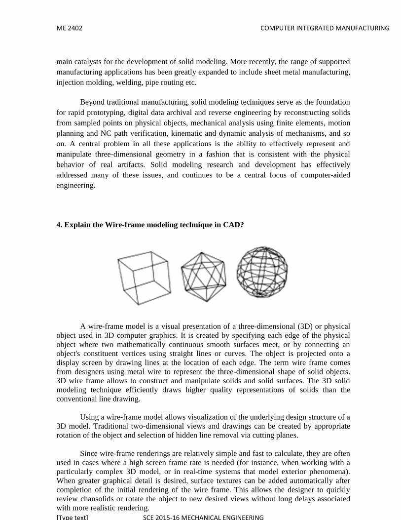
ME 2402 COMPUTER INTEGRATED MANUFACTURING
[Type text] SCE 2015-16 MECHANICAL ENGINEERING
main catalysts for the development of solid modeling. More recently, the range of supportedmanufacturing applications has been greatly expanded to include sheet metal manufacturing,injection molding, welding, pipe routing etc.
Beyond traditional manufacturing, solid modeling techniques serve as the foundationfor rapid prototyping, digital data archival and reverse engineering by reconstructing solidsfrom sampled points on physical objects, mechanical analysis using finite elements, motionplanning and NC path verification, kinematic and dynamic analysis of mechanisms, and soon. A central problem in all these applications is the ability to effectively represent andmanipulate three-dimensional geometry in a fashion that is consistent with the physicalbehavior of real artifacts. Solid modeling research and development has effectivelyaddressed many of these issues, and continues to be a central focus of computer-aidedengineering.
4. Explain the Wire-frame modeling technique in CAD?
A wire-frame model is a visual presentation of a three-dimensional (3D) or physicalobject used in 3D computer graphics. It is created by specifying each edge of the physicalobject where two mathematically continuous smooth surfaces meet, or by connecting anobject's constituent vertices using straight lines or curves. The object is projected onto adisplay screen by drawing lines at the location of each edge. The term wire frame comesfrom designers using metal wire to represent the three-dimensional shape of solid objects.3D wire frame allows to construct and manipulate solids and solid surfaces. The 3D solidmodeling technique efficiently draws higher quality representations of solids than theconventional line drawing.
Using a wire-frame model allows visualization of the underlying design structure of a3D model. Traditional two-dimensional views and drawings can be created by appropriaterotation of the object and selection of hidden line removal via cutting planes.
Since wire-frame renderings are relatively simple and fast to calculate, they are oftenused in cases where a high screen frame rate is needed (for instance, when working with aparticularly complex 3D model, or in real-time systems that model exterior phenomena).When greater graphical detail is desired, surface textures can be added automatically aftercompletion of the initial rendering of the wire frame. This allows the designer to quicklyreview chansolids or rotate the object to new desired views without long delays associatedwith more realistic rendering.

ME 2402 COMPUTER INTEGRATED MANUFACTURING
[Type text] SCE 2015-16 MECHANICAL ENGINEERING
The wire frame format is also well suited and widely used in programming tool pathsfor direct numerical control (DNC) machine tools.
Hand-drawn wire-frame-like illustrations date back as far as the ItalianRenaissance.[1] Wire-frame models were also used extensively in video games to represent3D objects during the 1980s and early 1990s when properly filled 3D objects would havebeen too complex to calculate and draw with the computers of the time. Wire-frame modelsare also used as the input for computer-aided manufacturing (CAM).
There are mainly three types of 3D CAD models. Wire frame is one of them and it isthe most abstract and least realistic. Other types of 3D CAD models are surface and solid.This method of modelling consists of only lines, points and curves defining the edges of anobject
5. Write the differences between the Solids vs. Surface Modeling? What and why youneed to know?
Computer aided design (CAD) isn’t like a car in that you can use it pretty well evenif you don’t know how it works. It pays to know what happening ‘under the hood’ whenusing CAD. It is important to know about surface and solids modeling because it does affectthe way you model, and it is important to know if you are switching platforms. It is also veryimportant to know about for rapid prototyping.
Surfaces and solids are the underlying math that defines the geometry of the formsyou create. There are three ways to define 3D geometry: solids, surfaces and wireframes.Wireframes don’t play much of a role in CAD, but primarily in digital content creation(DCC) and gaming.
The easiest way to understand the difference between surface and solids modeling isto think of a water balloon; the water in the balloon would be solids modeling, while thelatex skin would be surface modeling. Need more of an explanation? No problem.
Solids modeling
Solids modeling is defining an object with geometric mass. Solids modelingprograms usually create models by creating a base solid and adding or subtracting from itwith subsequent features. Features such as extrudes, extrude cuts, revolves, radii, chamfers,etc.
Examples of solids modeling programs are Solidworks, CATIA, and ProEngineer. Itwas originally developed for machine design, and is used heavily for engineering with largepart assemblies, digital testing and rapid prototyping.

ME 2402 COMPUTER INTEGRATED MANUFACTURING
[Type text] SCE 2015-16 MECHANICAL ENGINEERING
Surface modeling
Surface modeling is defining an object’s exterior with an infinitesimally thin skin.This skin is created by lofts, sweeps, and NURBS curves - i.e. sculptured surfaces with lotsof curvature. The surfaces are either defined by poles or guide curves. A surface isconsidered a solid only when it is completely enclosed. It is used to make technical surfaces(e.g. air plane wing) or aesthetic surfaces (e.g. car’s hood).
It was developed for the aerospace and automotive industries in the late 70s.Rhinoceros 3D and Alias Studio Tools are examples of a surface modeling programs. It isgenerally considered more difficult than solids modeling, but the models are more robustbecause the programs aren’t generally feature based. Later changes have to modify theexisting geometry as opposed to just editing the original feature, which is more difficult butkeeps the model from collapsing when one feature interferes with another.
6. Write the functions of various Edit and Inquiry commands in CAD?
Editing an entity or group of entities in Autocad requires the entity or the group tobe selected. There are three ways of doing this :
1) Autocad can be set to allow the user to select the objects first, and then accept commandsto process them. This is called noun/verb selection. This mode of operation can beenabled/disabled using the DDSELECT command which opens up a dialogue box.
2) The commands can be given first, and the objects can be specified when the user isprompted for them.
3) The SELECT command can be used to select a specific selection set, which can bereferred to in subsequent editing operations.
Editing with grips :Selected objects can be edited by manipulating grips that appear on the selected entity. TheGrips mode can be enabled with the DDGRIPS command which opens up a dialogue box.The editing operations possible using grips are :
Stretch, Move, Rotate, Scale and Mirror
7. Erasing unwanted objects and retrieving accidentally removed ones :The ERASE command permanently removes specified objects. To erase only the drawnobject, enter "L" at the 'select oblects' prompt.
8. The OOPS command restores only the most recently erased objects.9. Copying and Moving :

ME 2402 COMPUTER INTEGRATED MANUFACTURING
[Type text] SCE 2015-16 MECHANICAL ENGINEERING
The commands available are :MOVE, COPY, ROTATE, SCALE, MIRROR, STRETCH and ARRAYThe MOVE and COPY commands are for recreating the object at another place.The COPY command retains a copy in the original place while the MOVE command doesnot.
10. The SCALE command allows the size of objects to be changed. It scales theobject about a reference point, by expanding/shrinking it equally in all directions.SCALE can be used to rescale an entire drawing in one go.
11. The ARRAY command creates multiple copies of entities in a rectangular or polarpattern. To change the orientation of the array, use SNAP Rotate command orSNAPANG system variable.
12. Changes, Cuts and Constructions : These commands allow you to changeproperties of objects (like color, layer,etc.) and modify objects by trimming/extending their ends, and cutting sections out of them. They can also be used todraw fillet arcs, chamfer lines, parallel lines, offset curves, and construction markers.
The available commands are :
CHANGE, DDEDIT, BREAK, TRIM, EXTEND, FILLET, CHAMFER, OFFSET, DIVIDE,and MEASURE
The CHANGE command is used to change the following :color, elevation, layer, linetype, thickness
Characteristics other than the above can also be changed by specifying a pointinstead of choosing one of the above properties. Then this "change point" is used to modifythe object depending on whether the object is a line or a circle, etc. The "change point"method works for multiple entities also.
Variations of the CHANGE command are : DDCHPROP and CHPROP
The DDEDIT command allows editing of both text and attribute definitions. Thecommand can be used either in paper space or in model space, whichever is activewhen the command is issued. It cannot be used on text attributes that are part of ablock.
The BREAK command erases part of a line, trace, circle, arc or 2D polyline Theend points of the part are specified by the user.
The TRIM command is used to trim objects such that they end exactly at cuttingedges defined by other intersecting objects.

ME 2402 COMPUTER INTEGRATED MANUFACTURING
[Type text] SCE 2015-16 MECHANICAL ENGINEERING
The EXTEND command is the complement of the TRIM command because it letsyou extend an object till it meets another object.
The FILLET command connects two lines, arcs or circles by means of a smoothlyfitted arc of specified radius.
The CHAMFER command is similar : it trims two intersecting lines a specifieddistance from the intersection and connects the trimmed ends with a new linesegment.
The OFFSET command constructs an entity parallel to the specified one, eitherthrough a given point or at a given distance.
The DIVIDE command lets you divide an entity into several equal-length parts,placing markers along the object at the dividing points.
The MEASURE command is similar to the DIVIDE command : it measures anentity and places markers at specified intervals.
Polyline, Mesh, and Block Editing :
There are two basic commands for this : PEDIT and EXPLODE. PEDIT is used to edit 2Dand 3D polylines, and 3D polygon meshes.The EXPLODE command breaks up a complex entity as follows :A Block or associative Dimension is replaced with copies of simple entities comprising theBlock or Dimension. Polylines are replaced with simple and arcs; 3D polygon meshes with3D faces and polyface meshes with 3D faces, lines and points.
Undoing commands : U command : causes the most recent command to be undone. REDO command : reverses the effect of the most recent U command.
UNDO command : can undo several commands simultaneously. Inquiry commands are commands which allow the user to inquire into locations
and relationships into entities. Inquiry commands available in Autocad are : LIST : lists data for an entity.
DBLIST : lists data for every entity in the drawing. ID : gives co-ordinates of a point specified in the graphics window.
DIST : measures angle and distance between two points. AREA : finds are of specified enclosure.
UNIT – II – COMPONENTS OF CIM
Part - A (2 Marks)

ME 2402 COMPUTER INTEGRATED MANUFACTURING
[Type text] SCE 2015-16 MECHANICAL ENGINEERING
1. CIMComputer-integrated manufacturing (CIM) is the manufacturing approach of using
computers to control the entire production process.CIM is the integration of the total manufacturing enterprise through the use of
integrated systems and data communication coupled with new managerial philosophiesthat improve organizational and personnel efficiency.
Computer integrated manufacturing is defined as the effective use of computers todesign the products, plan the production ,control the operations and perform the variousbusiness related functions needed in a manufacturing firm.
2. What is the main objective of CIM? The main aim of CIM is to use the advanced information processing
technology into all areas of manufacturing industry in order
To make the total process more productive and efficient; increase product reliability; Decrease the cost of production and maintenance relating to the
manufacturing system as well as to the product; and Reduce the number of hazardous jobs and
3. Automation.Automation may be defined as the process of having machines follow a
predetermined sequence of operations with little or no human labor, using specializedequipment and devices that perform and control manufacturing processes.
4. ‘Islands of automationThe individually automated workstations or processes are called islands of
automation. In other words the term ‘islands of automation’ represents the varioustechnologies that facilitate manufacturing automation in isolation, without havingintegrated with other manufacturing technologies.
5. Difference between CAD, CAM AND CIM CAD/CAM involves the use of computers to make Design and Manufacturing more
profitable. Parts of CIM use CAD/CAM techniques and products to try and make the factory
fully connected using computers. The essential difference is CAD/CAM provides the tools, CIM is the philosophy
which is used when organizing the computers, programs, etc. and all the informationthat flows between them.
CIM focuses on connecting the various CAD/CAM modules.
6. Computer-aided technologies Computer-aided technologies (CAx) is a broad term that means the use of computer
technology to aid in the design, analysis, and manufacture of products. Advanced CAx tools merge many different aspects of the product lifecycle
management (PLM), including design, finite element analysis (FEA), manufacturing,production planning, product

ME 2402 COMPUTER INTEGRATED MANUFACTURING
[Type text] SCE 2015-16 MECHANICAL ENGINEERING
Computer-aided design (CAD) Computer-aided engineering (CAE)
Computer-aided industrial design (CAID) Computer-aided manufacturing (CAM)
Computer-aided requirements capture (CAR) Computer-aided rule definition (CARD)
Computer-aided rule execution (CARE) Computer-aided software engineering (CASE) Computer-assisted surgery (CAS)
Computer-aided surgical simulation (CASS) Computational fluid dynamics (CFD)
Component information system (CIS) Computer-integrated manufacturing (CIM)
7. CIM system – Hardware & Software. CIM Hardware consists of manufacturing equipments and Computer related
hard ware with the office equipment. CIM Software consists of computer programs to carry out the various
functions and transfer the data from various areas of the industry.
8. CIM Wheel or CIM Components:
Distinct components of CIM wheel Manufacturing / Human resource management Marketing
Strategic planning Finance
Product and process design and planning Manufacturing planning and control Factory automation
9. Computer communication network in CIM Communication in the nervous systems of CIM and this is an integral part of
CIM.

ME 2402 COMPUTER INTEGRATED MANUFACTURING
[Type text] SCE 2015-16 MECHANICAL ENGINEERING
The development in communication / network engineering have madeimplement of CIM easier that before.
10. What are the various communication needs of CIM? The information need for manufacturing in a company requires as follows. Person-to-person, computer-to-computer, machine-to-machine, person to
computer or computer to person, person to machine or machine to person,computer to machine or machine to computer
11. What are the fundamental needs of computer communications? Data: entities that convey meaning Information: the content or interpretation of data Signals: electric or electromagnetic encoding of data
Signaling: the act of propagating the signal along a medium Transmission: propagating of data by processing of signals
12. What are the nine major elements of CIM systems?Marketing, Product design, Planning, Purchase, Manufacturing engineering,
Factory automation hardware, warehousing, finance, and Information management
13. Data Transmission Methods. Serious & Parallel Communications. Synchronous & Asynchronous methods.
Simplex & Duplex methods.
15. Types of Computer networksThe computer networks can be classified into four categories depending upon
the physical separations of the communication devices.
Miniature - <50m
Small - <500m Medium - <1km Large - >1km - WAN & LAN.
16. Local Area Network;Local Area Network is intended to serve a number of users who are
physically located close together.
17. Wide Area Network;Wide Area Network more like to telephone network, tying different people in
different buildings, cities or even countries.
18. Network Topologies.There are several commonly used network topology or ways of routing the
interconnections. It classified as Star, Ring, Bus topologies.
19. Seven Layers of OSI model.

ME 2402 COMPUTER INTEGRATED MANUFACTURING
[Type text] SCE 2015-16 MECHANICAL ENGINEERING
The protocol layers are;
1. Physical layer,2. Data link layer,3. Network layer,4. Transport layer,5. Session layer,6. Presentation layer,7. Application layer.
20. Components of LAN;The various components of LAN are listed below;
Computers,
Network interface card, Network cable, Network server,
Central mass storage.
21. Database The data base can be defined as a collection data in a single location
defined to be used by different programmers for a variety ofapplications.
The database of a company will include data required for variousdepartments like design, purchase, manufacturing technology,personnel, marketing and sales, finance inventory etc.
22. Differentiate data and information.The data refers to the value stored in the database and information to
the meaning as understood by the user.
23. Network Topologies.
There are several commonly used network topology or ways of routing theinterconnections. It classified as Star, Ring, Bus topologies.
Star network communicationsThe star network consists of a central control station to which each of the individual
devices or user stations are connected. To send messages from one workstation to the otheris through the central station.
Ring network communicationIn ring network communication the individual stations are connected in a continuous
ring .Each station has a neighboring station on either side. To communicate from one stationto other, the message must be relayed from station to station until it finally arrives at itsdesignated destination station.

ME 2402 COMPUTER INTEGRATED MANUFACTURING
[Type text] SCE 2015-16 MECHANICAL ENGINEERING
Bus network communicationThe bus network consists of a single main transmission line to which the individual
devices are attached. Any device or station can communicate with any other device in thenetwork by sending its message through the bus with the address of the desired recipient.
Reasons for having database for the company Redundancy can be reduced
Inconsistency can be avoided The data can be shared
Standards can be enforced Security restrictions can be applied
Integrity can be maintained Conflicting requirements can be balanced
Different types of design data related to CIM Standards-national, international, trade or company standards Material specifications and properties
Design theories and rules of thumb. Data based on experience
Test results of products and proto types Service feedback Results of analysis of the product
Data’s on competitor’s product.
Part - B ( 16 Marks)1. Explain the CIM system.
Computer-integrated manufacturing (CIM) is the manufacturing approach of usingcomputers to control the entire production process. This integration allows individualprocesses to exchange information with each other and initiate actions. Through theintegration of computers, manufacturing can be faster and less error-prone, although themain advantage is the ability to create automated manufacturing processes. Typically CIMrelies on closed-loop control processes, based on real-time input from sensors. It is alsoknown as flexible design and manufacturing.
A computer-integrated manufacturing system is not the same as a "lights-out"factory, which would run completely independent of human intervention, although it is a bigstep in that direction. Part of the system involves flexible manufacturing, where the factorycan be quickly modified to produce different products, or where the volume of products canbe changed quickly with the aid of computers. Some or all of the following subsystems maybe found in a CIM operation:

ME 2402 COMPUTER INTEGRATED MANUFACTURING
[Type text] SCE 2015-16 MECHANICAL ENGINEERING
Computer integrated manufacturing(CIM) is a broad term covering all technologiesand soft automation used to manage the resources for cost effective production of tangiblegoods. Integration – capital, human, technology and equipment CIM – which orchestrates the factors of production and its management. CIM is being projected as a panacea for Discrete manufacturing type of industry,
which produces 40% of all goods.
“CIM is not applying computers to the design of the products of the company. That iscomputer aided design (CAD)! It is not using them as tools for part and assembly analysis.That is computer aided engineering (CAE)! It is not using computers to aid the developmentof part programs to drive machine tools. That is computer aided manufacturing (CAM)!
It is not materials requirement planning (MRP) or just-in-time (JIT) or any othermethod of developing the production schedule. It is not automated identification, datacollection, or data acquisition. It is not simulation or modeling of any materials handling orrobots or anything else like that. Taken by themselves, they are the application of computertechnology to the process of manufacturing. But taken by themselves they only crate theislands of automation.”
Definition of CIM:It describes integrated applications of computers in manufacturing. A number of
observers have attempted to refine its meaning:One needs to think of CIM as a computer system in which the peripherals, instead of
being printers, plotters, terminals and memory disks are robots, machine tools and otherprocessing equipment. It is a little noisier and a little messier, but it’s basically a computersystem.
CIM is a management philosophy, not a turnkey computer product. It is a philosophycrucial to the survival of most manufacturers because it provides the levels of product designand production control and shop flexibility to compete in future domestic and internationalmarkets.
CIM is an opportunity for realigning your two most fundamental resources: peopleand technology. CIM is a lot more than the integration of mechanical, electrical, and eveninformational systems. It’s an understanding of the new way to manage.
“CIM is the integration of the total manufacturing enterprise through the use ofintegrated systems and data communications coupled with new managerial philosophies thatimprove organizational and personnel efficiency.”
Concept or Technology“Some people view CIM as a concept, while others merely as a technology. It is
actually both. A good analogy of CIM is man, for what we mean by the word manpresupposes both the mind and the body. Similarly, CIM represents both the concept and thetechnology. The concept leads to the technology which, in turn, broadens the concept.”The meaning and origin of CIM
The CIM will be used to mean the integration of business, engineering,manufacturing and management information that spans company functions from marketingto product distribution

ME 2402 COMPUTER INTEGRATED MANUFACTURING
[Type text] SCE 2015-16 MECHANICAL ENGINEERING
2. Briefly Explain the CIM system?The CIM system consists of Hardware & Software
CIM Hardware consists of manufacturing equipments and Computer relatedhard ware with the office equipment.
CIM Software consists of computer programs to carry out the variousfunctions and transfer the data from various areas of the industry.
Elements of CIM hardware;Manufacturing equipment such as CNC machines, robots, DNC / FMS systems, work
holding and tool handling devices, Storage devices, sensors, shop floor data collectiondevices, inspection machine etc.Computers ,Controllers, CAD /CAM systems,workstations, data entry terminals, bar code readers, printers ,plotters, modems, cables,connectors etc.
Elements of CIM software; MIS- management information system
Sales, marketing, finance Data base management
Modeling and design Analysis, simulation, communications Monitoring, production control
Manufacturing area control, job tracking Inventory control
Shop floor data collection, Order entry, materials handling, Device drivers,
Process planning, manufacturing facilities Work flow automation, Business process engineering, Network management
2. Explain the communication networks in CIM
Communication Networks;A communication network is the backbone of an enterprise integration. Networks
help to unify a company by linking together all the computerized devices irrespective of theirphysical location. Through networks the whole enterprise can be integrated, includingsuppliers and customers.
For example, sales and marketing can send customer requirements for new productsto design engineering. A CAD generated bill of materials can then be transferred to “materialrequirements planning(MRP)” systems. Product design information can be transmitted tomanufacturing for use in process planning.There are wo main types of communication networks:
1) Telecommunication Networks;2) Computer communication Networks.

ME 2402 COMPUTER INTEGRATED MANUFACTURING
[Type text] SCE 2015-16 MECHANICAL ENGINEERING
Telecommunication network is mainly used for voice communication. Computercommunication network is a system of interconnected computers and other devices capableexchanging information.
Types of Computer networks;The computer networks can be classified into four categories depending upon the
physical separations of the communication devices. Miniature - <50m Small - <500m
Medium - <1km Large - >1km - WAN & LAN.
Local Area Network;Local Area Network is intended to serve a number of users who are physically
located close together.Wide Area Network;
Wide Area Network more like to telephone network, tying different people indifferent buildings, cities or even countries.
Network Topologies.There are several commonly used network topology or ways of routing the
interconnections. It classified as Star, Ring, Bus topologies.
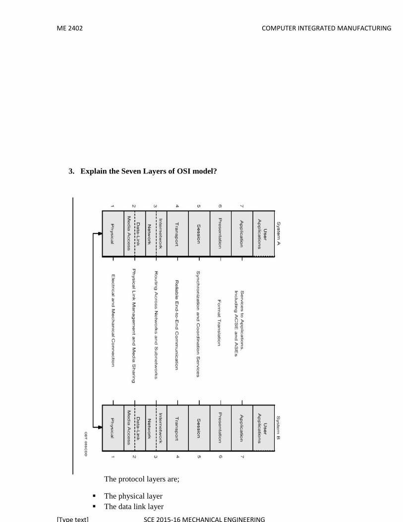
ME 2402 COMPUTER INTEGRATED MANUFACTURING
[Type text] SCE 2015-16 MECHANICAL ENGINEERING
3. Explain the Seven Layers of OSI model?
The protocol layers are;
The physical layer The data link layer

ME 2402 COMPUTER INTEGRATED MANUFACTURING
[Type text] SCE 2015-16 MECHANICAL ENGINEERING
The network layer The transport layer The session layer The presentation layer The application layer
4. Explain the various topologies in the communication in CIM?
Network Topologies; Star topology Ring topology Bus topology Tree topology
There are several commonly used network topology or ways of routing theinterconnections. It classified as Star, Ring, Bus topologies.Star network communications
The star network consists of a central control station to which each of the individualdevices or user stations are connected. To send messages from one workstation to the otheris through the central station.
Ring network communicationIn ring network communication the individual stations are connected in a continuous
ring .Each station has a neighboring station on either side. To communicate from one stationto other, the message must be relayed from station to station until it finally arrives at itsdesignated destination station.
Bus network communicationThe bus network consists of a single main transmission line to which the individual
devices are attached. Any device or station can communicate with any other device in thenetwork by sending its message through the bus with the address of the desired recipient.
5. Explain the Basic Elements of Automation?

ME 2402 COMPUTER INTEGRATED MANUFACTURING
[Type text] SCE 2015-16 MECHANICAL ENGINEERING
Manufacturing Support System
Basic Elements of Automation;An automation control system consist of three basic elements1. Power to accomplish the process and operate the system2. A program of instruction to direct the process3. a control system to actuate the instructions.The relationship amongst these elements is illustrated in below mentioned figure. All
the systems that quality as being automated includes these three basic elements in one form oranother.
Enterprise level
automated system is used to operate some process, and power is required to drive theprocess as well as the controls. The principal source of the power in automated system iselectrical power has many advantages in automated as well as no automated processes.
1) POWER FOR THE PROCESSIn production, the term process refers to the manufacturing operation that is
performed on a work unit. Most of the power in manufacturing plants is consumed by theseskinds of operations. The "power form" indicated in the middle column of the table refers to
Manufacturing System
Automation andControl technologies
Material HandlingTechnologies
Manufacturing Processes and Assembly operations
Quality ControlSystems
ME 2402 COMPUTER INTEGRATED MANUFACTURING
[Type text] SCE 2015-16 MECHANICAL ENGINEERING
the energy that is applied directly to the process. As indicated above, the power source foreach operation is often converted from electricity.
LOADING AND UNLOADING THE WORK UNIT:Parts must be moved into the proper position and orientation for the process
to be performed, and power is required for this transport and placement function. at theconclusion of the process, the work unit must similarly be removed. If the process iscompletely automated, then some form of mechanized power is used. If the process ismanually operated or semi automated, then human power may be used to position and locatethe work unit.
MATERIAL TRANSPORT BETWEEN OPERATIONS:In addition to loading and unloading at a given operation, the work unit must
be moved between operations.2) POWER FOR AUTOMATION:
Above and beyond the basic power requirements for the manufacturing operation,additional power is required for automation. The additional power is used for the followingfunctions:
CONTROLLER UNIT;
Modern industrial controllers are based on digital computers, which require electricalpower to read the program of instructions, make the control calculations, and execute theinstructions by transmitting the proper commands to the actuating devices.
POWER TO ACTUATE THE CONTROL SIGNALS;
The commands sent by the controller unit are carried out by means ofelectromechanical devices, such as switches and motors called actuators. The commands aregenerally transmitted by means of low-voltage control signals.
DATA ACQUISITION AND INFORMATION PROCESSING;
In most control systems, data must be collected from the process and used asinput to the control algorithms. In addition, a requirement of the process may includekeeping records of process performance or product quality. These data acquisition in modestamounts.\2.) PROGRAM OF INSTRUCTIONS:-
The actions performed by an automated process are defined by a program ofinstructions. Whether the manufacturing operation involves low, medium, or highproduction. each part or product made in the operation requires one or more processing stepsthat are unique to that part or product. These processing steps are performed during a workcycle. A new part is completed during each work cycle. The particular processing steps forthe work cycle are specified in a work cycle program. Work cycle programs are called partprograms in numerical control
3) CONTROL SYSTEMSThe control element of the automated system executed the program of instructions,
the control system causes the process to accomplish is defined function, to carry out somemanufacturing operation. let us provide a brief introduction to control systems here.
The control systems in an automated system can be either closed loop or open loop. a

ME 2402 COMPUTER INTEGRATED MANUFACTURING
[Type text] SCE 2015-16 MECHANICAL ENGINEERING
Controller
closed loop control system, also known as feed back control system, is one in which theoutput variables is compared with an input parameter, and any difference between the two isused to drive the output into agreement with the input, as shown in below mentioned figure.a closed loop control system consists of 6 basic elements.
Input parameter OutputParameter
7. Explain the advanced Automation function?In addition to executing work cycle programs, an automated system may be capable
of executing advanced functions that are specific to a particular work unit. In general, thefunctions are concerned with enhancing the safety and performance of the equipment.Advanced automation functions include the following(1) Safety monitoring,(2) Maintenance and repair diagnostics, and(3) Error detection and recovery.
automation functions are made possible by special subroutines included in theprogram of instructions. In some cases, the functions provide information only and do notinvolve any physical actions by the control systems, for example reporting a list ofpreventive maintenance tasks that should be accomplished. Any actions taken on the basis ofthis report are decided by the human operations and managers of the systems and not by thesystem itself. In other cases, the program of instructions must be physically executed by thecontrol system using available actuators. A simple example of this case is a safetymonitoring system that sounds an alarm when a human worker gets dangerously close to theautomated equipment.
One of the significant reasons for automating a manufacturing operation is to removeworkers from a hazardous working environment. An automated system is often installed toperform a potentially dangerous operation that would otherwise be accomplished manfullyby human workers. However, even in automated systems, workers are still needed to servicethe system at periodic intervals if not full-time, accordingly, it is important that theautomated system be designed to operate safety when workers are in attendance. In addition,it is essential that the automated system carry out it is process in a way that is not self-destructive. Thus, there are two reasons for providing an automated system with a safetymonitoring capability:
(1) to product human workers in the vicinity of the system and(2) to product the equipment associated with the system.
Safety monitoring means more than the conventional safety measures taken in a
Feed Back Sensor
ProcessActuator

ME 2402 COMPUTER INTEGRATED MANUFACTURING
[Type text] SCE 2015-16 MECHANICAL ENGINEERING
manufacturing operation, such a productive shield around the operation or the kinds ofmanual devices that might be utilized by human workers such as emergency stop buttons.Safety monitoring in an automated system involves the uses of sensors to track the systemsoperation and identify conditions and events that are unsafe or potentially unsafe. The safetymonitoring system is programmed to respond to unsafe conditions in some appropriate way.Possible responses to various hazards might include one more of the following:
1. completely stopping the automated system,2. sounding an alarm3. reducing the operating speed of the process,4. Tacking corrective actions to recover from the safety violation.This last response is the most sophisticated and is suggestive of an intelligent machine
performing some advanced strategy. This kind of response is applicable to a variety ofpossible mishaps, not necessarily confined to safety issues, and is called error detection andrecovery
Sensors for safety monitoring range from very simple devices to highly sophisticatedsystems. The following list suggests some of the possible sensors and their applications forsafety monitoring: Limit switches to detect proper positioning of a part in a work holding devices so that
the processing cycle can begin. Photoelectric sensors trigged by the interruption of a light beam; this could be used to
indicate that a part is in the proper positions or to detect the pressure of a humanintruder in the work cell.
Temperature sensors to indicate the metal work part is hot enough to proceed withhot forging operations. if the work part is not sufficiently heated, then the metalsductility might be too low, and the forging dies might be damaged during theoperations.
UNIT – III – GROUP TECHNOLOGY ANDCOMPUTER AIDED PROCESS PLANNING
Part - A (2 Marks)1. Group technology (GT)
Group technology (GT) is a manufacturing philosophy to increase productionefficiency by grouping a variety of parts having similarities of shape, dimension, and/orprocess route.2. Part family
A part family is a collection of parts which are similar either because of geometricshape and size or because similar processing steps are required in their manufacture.Design attributes:
Part configuration (round or prismatic)
Dimensional envelope (length to diameter ratio) Surface integrity (surface roughness, dimensional tolerances)
Material type & Raw material state (casting, forging, bar stock, etc.)
Part manufacturing features: Operations and operation sequences (turning, milling, etc.)

ME 2402 COMPUTER INTEGRATED MANUFACTURING
[Type text] SCE 2015-16 MECHANICAL ENGINEERING
Batch sizes Machine tools
Cutting tools Work holding devices
Processing times
3. General methods used for part families.4. Visual inspection,5. Parts classification and coding system, and6. Production flow analysis.
4. Production Flow analysisProduction Flow analysis (PFA) is a method for identifying part families and
associated machine groupings that uses the information contained on production route sheetsrather on part drawings.
5. Code structures used in GT application Attribute codes (or polycodes or chain type structure).
Hierarchical codes (or monocodes or tree structure). Decision-tree codes (or hybrid codes or mixed codes).
6. Coding systems.1. Opitz classification system, 2. MICLASS system,
3. DCLASS system, 4. CODE system,5. KK-3 system,and 6. CUTPLAN system.
7. Benefits of Group TechnologyGroup technology is a management strategy to help eliminate waste caused by
duplication of effort.It affects all areas of a company, including:
Engineering Equipment specification
Facilities planning Process planning
Production control Quality control Tool design
Purchasing Service
7. Cellular manufacturingCellular manufacturing (CM) is an application of group technology in which
dissimilar machines have been aggregated into cells, each of which is dedicated to theproduction of a part family.8. Design considerations guiding the cell-formation.
Parts/products to be fully completed in the cell. Higher operator utilization.

ME 2402 COMPUTER INTEGRATED MANUFACTURING
[Type text] SCE 2015-16 MECHANICAL ENGINEERING
Fewer operations than equipment. Balanced equipment utilization in the cell.
9. Process planningProcess Planning is the systematic determination of the methods by which a product
is to be manufactured, economically and competitively.
10. Computer/Aided Process Planning CAPP refers to computer/aided process planning. CAPP is used to overcome the drawbacks of manual process planning. With the use of computers on the process planning one can reduce the routineclerical work of manufacturing engineers. Also it provides the opportunity to generate rational, consistent and optimalplans.
11. Process planning techniques used in the modern manufacturing technologies Manual approach Computer aided process planning techniques Retrieval type CAPP system (Variant type CAPP system) Generative type CAPP system
12. CAPP;Computer aided process planning system offers the potential for reducing the routine
clerical work of manufacturing engineers. It provides the opportunity to generate routingswhich are rational, consistent and perhaps even optimal.13. Retrieval type CAPP (Variant type) systems
For each part family a standard process plan is established and stored in computerfiles and then it is retrieved for new work parts which belong to that family. Because of thealterations that are made in the retrieved process plan, the CAPP system is known as variantsystem.14. Generative CAPP system
Generative process planning involves the use of computer to create an individualprocess plan automatically without human assistance. The computer would employ a set ofalgorithms to progress through the various technical and logical decisions toward a finalplan.
15. Role of process planning1. Interpretation of product design data2. Selection of machining processes.3. Selection of machine tools.4. Determination of fixtures and datum surfaces.5. Sequencing the operations.6. Selection of inspection devices.
Part - B ( 16 Marks)

ME 2402 COMPUTER INTEGRATED MANUFACTURING
[Type text] SCE 2015-16 MECHANICAL ENGINEERING
1. Explain the various benefits of GT?
Group technology is a manufacturing philosophy in which similar parts areidentified and grouped together to take the advantage of their similarities in manufacturingand design. Similar parts are arranged in to part families.
Advantages of group technology Product design benefits- 10 % reduction in the number of drawings
Tooling and setup benefits – 69 % reduction of setup time. Materials handling benefits
Production and inventory control benefits -70 % reduction in production time
-62 % reduction in work in process inventories -82 % reduction in overdue orders Employee satisfaction
Process planning procedures
Group technology (GT);Group technology (GT) is a manufacturing philosophy to increase production
efficiency by grouping a variety of parts having similarities of shape, dimension, and/orprocess route.Part family;
A part family is a collection of parts which are similar either because of geometricshape and size or because similar processing steps are required in their manufacture.Design attributes:
Part configuration (round or prismatic)
Dimensional envelope (length to diameter ratio) Surface integrity (surface roughness, dimensional tolerances)
Material type Raw material state (casting, forging, bar stock, etc.)
Manufacturing attributes: Operations and operation sequences (turning, milling, etc.) Batch sizes
Machine tools Cutting tools
Work holding devices Processing times.
General methods used for part families;1. Visual inspection,2. Parts classification and coding system, and3. Production flow analysis.
ME 2402 COMPUTER INTEGRATED MANUFACTURING
[Type text] SCE 2015-16 MECHANICAL ENGINEERING
2. List out the Benefits of Group Technology?
Group technology, when successfully implemented, offers many benefits to industries.GT benefits can be realized in a manufacturing organization in the following areas:
6. Production design7. Tooling and setups8. Materials handling9. Production and inventory control10. Process planning Management and employees.
1. Benefits in product DesignThe main advantages of GT for product design come in cost and time savings,
because design engineers can quickly and easily search the database for parts that eitherpresently exist or can be used with slight modifications, rather than issuing new partnumbers.
A similar cost savings can be realized in the elimination of two or more identical partswith different part numbers. Another advantage is the standardization of designs. Designfeatures such as corner radii, tolerances, chamfers, counter bores and surface finishes can bestandardized with GT.
2.Benefits in Tooling and SetupsIn the area of tooling, group jigs and fixtures are designed to accommodate every
member of a part family. Also work holding devices are designed to use special adapters insuch a way that this general fixture can accept each part family member. Since setup timesare very short between parts in a family, a group layout can also result in dramatic reductionsin setup times.
3.Benefits in material handling:GT facilitates a group layout of the shop. Since machines are arranged as cells, in a
group layout, the materials handling cost can be reduced by reducing travel and facilitatingincreased automation.
4.Benefits in production and inventory ControlGT simplifies production and planning control. The complexity of the problem has
been reduced from a large portion of the shop to smaller groups of machines. The productionscheduling is simplified to a small number of parts through the machines in that cell.
5.Benefits in Process PlanningThe concept of group technology – parts classification and coding – lead to an
automated process planning system. Grouping parts allows an examination of the variousplanning/route sheets for all members of a particular family. Once this has beenaccomplished, the same basic plans can be applied to other members, thereby optimizing theshop for the group.
6.Benefits to Management and EmployeesIt is understood that GT simplifies the environment of the manufacturing firm, which
provides significant benefit to management. Simplification reduces the cumbersome paper work. Simplification also improves the work environment.
In the GT work environment, the supervisor has in – depth knowledge of the workperformed and better control.

ME 2402 COMPUTER INTEGRATED MANUFACTURING
[Type text] SCE 2015-16 MECHANICAL ENGINEERING
3. Explain the Cellular manufacturing in CIM?
Cellular manufacturing (CM) is an application of group technology in whichdissimilar machines have been aggregated into cells, each of which is dedicated to theproduction of a part family. The machines in a multi station system with variable routingmay be manually operated, semi-automatic, or fully automated. When manually operated orsemi automatic the machine groups are often called machine cells, and the use of these cellsin a factory is called cellular manufacturing.Design considerations guiding the cell-formation.;
Parts/products to be fully completed in the cell. Higher operator utilization. Fewer operations than equipment.
Balanced equipment utilization in the cell.
Types of cell design5. Single machine cell6. Group machine cell with manual handling7. Group machine cell with semi-integrated handling8. Flexible manufacturing system9. Explain the Computer Aided Process planning in CIM?
Process Planning is the systematic determination of the methods by which a productis to be manufactured, economically and competitively.
Role of process planning1. Interpretation of product design data2. Selection of machining processes.3. Selection of machine tools.4. Determination of fixtures and datum surfaces.5. Sequencing the operations.6. Selection of inspection devices.7. Determination of production tolerances.8. Determination of the proper cutting conditions.9. Calculation of the overall times.10. Generation of process sheets including NC data.
Process planning techniques; Manual approach Computer aided process planning techniques Retrieval type CAPP system (Variant type CAPP system) Generative type CAPP system
Computer/Aided Process Planning; CAPP refers to computer/aided process planning. CAPP is used to overcome the drawbacks of manual process planning. With the use of computers on the process planning one can reduce the routine
clerical work of manufacturing engineers.
ME 2402 COMPUTER INTEGRATED MANUFACTURING
[Type text] SCE 2015-16 MECHANICAL ENGINEERING
Also it provides the opportunity to generate rational, consistent andoptimal plans.
CAPP;Computer aided process planning system offers the potential for reducing the routine
clerical work of manufacturing engineers. It provides the opportunity to generate routingswhich are rational, consistent and perhaps even optimal.
Retrieval type CAPP (Variant type) systems;For each part family a standard process plan is established and stored in computer
files and then it is retrieved for new work parts which belong to that family. Because of thealterations that are made in the retrieved process plan, the CAPP system is known as variantsystem.
Generative CAPP system;Generative process planning involves the use of computer to create an individual
process plan automatically without human assistance.The computer would employ a set ofalgorithms to progress through the various technical and logical decisions toward a finalplan.
10. Explain in detail the Generative and Variant approaches in process planningand differentiate both approaches?
Generative approaches in Computer aided manufacturing process planning;In the generative approach, an automatic computerized system is used to synthesize
or generate each individual process plan automatically and without reference to any priorplan. The automatic computerized system normally consists of decision logic, formulas,technology algorithms and geometry based data to uniquely determine the many processingdecisions required for generating process plans.
Unlike the retrieval CAPP no standard manufacturing plans are predefined or stored.Instead, the computer automatically generates a unique operation/ route sheet whenever thepart is ordered.
Thus the generative CAPP system automatically generates the process plan based ondecision logics and pre-coded algorithms. The computer stores the rules of manufacturingand the equipment capabilities (not any group of process plans).
When using a system, a specific process plan for a specific part can be generatedwithout any involvement of a process planner. The human role in running the systemincludes(i) inputting the GT code of the given part design, and (ii) monitoring the function.Components of Generative CAPP systemThe various components of a generative system are,
A part description, which identifies a series of component characteristics, includinggeometric features, dimensions, tolerances and surface condition.
A subsystem to define the machining parameters for example using look – up tablesand analytical results for cutting parameters.
A subsystem to select and sequence individual operations.

ME 2402 COMPUTER INTEGRATED MANUFACTURING
[Type text] SCE 2015-16 MECHANICAL ENGINEERING
Decision logic is used to associate appropriate operations with feautures of acomponent, and heuristics and algorithms are used to calculate operation steps, timesand sequences.
A database of available machines and tooling. A report generator which prepares the process plan report.
Advantages of Generative CAPPThe generative CAPP has the following advantages:
It can generate consistent process plans rapidly. New components can be planned as easily as existing components.
It has potential for integrating with an automated manufacturing facility to providedetailed control information.
Variant or Retrieval approaches in Computer aided manufacturing process planning;A retrieval CAPP system, also called a variant CAPP system, has been widely used
in machining applications. The basic idea behind the retrieval CAPP is that similar parts willhave similar process plans.
In this system., a process plan for a new part is created by recalling., identifying andretrieving an existing plan for a similar part, and making the necessary modifications for thenew part.
In fact, the variant CAPP is a computer – assisted extension of the manual approach.The computer assists by providing an efficient system for data management, retrieval ,editing and high speed printing of the process plans. The retrieval CAPP system has thecapacity to alter an existing process plan. That’s why it is also known as variant CAPPsystem.
Procedure for using Retrieval CAPP systemA retrieval CAPP system is based on the principles of group technology (GT) and
parts classification and coding. In this system, for each part family a standard process plan(i.e., route sheet) is prepared and stored in computer files. Through classification and coding,a code number is generated. These codes are often used to identify the part family and theassociated standard plan. The standard plan is retrieval and edited for the new part.Variant CAPP system procedure.Step 1 :Define the coding scheme
Adopt existing coding or classification schemes to label parts for the purpose ofclassification. In some extreme cases, a new coding scheme maybe developed.Step 2 :Group the parts into part families
Group the part families using the coding scheme defined in Step 1. based on somecommon part features. A standard plan is attached to each part family (see step 3) . Often, anumber of part types are associated with a family, thereby reducing the total number ofstandard process plan.Step 3: Develop a standard process plan for each part family based on the common featuresof the part types. This process plan can be used for every part type within the family withsuitable modifications.Step 4.: Retrieve and modify the standard plan:

ME 2402 COMPUTER INTEGRATED MANUFACTURING
[Type text] SCE 2015-16 MECHANICAL ENGINEERING
When a new part enters the system, it is assigned to a part family based on the coding andclassification scheme. Then the corresponding standard process plan is retrieved andmodified to accommodate the unique features of the new part.Advantages of Retrieval CAPP system:
Once a standard plan has been written, a variety of parts can be planned. Comparatively simple programming and installation ( compare with generative
CAPP systems) is required to implement a planning system. Efficient processing and evaluation of complicated activities and decisions, thus
reducing the time and labour requirements.
Standardized procedures by structuring manufacturing knowledge of the processplanners to company’s needs.
Lower development and hardware costs. Shorter development times.
The system is understandable, and the planner has control of the final plan. It is easy to learn and easy to use.
Draw backs of Retrieval CAPP system The components to be planned are limited to similar components previously planned. Maintaining consistency in editing is difficult. Experienced process planners are still required to modify the standard plan for the
specific component.
7. How parts are classified and coded in Group Technology? Illustrate the same for aproduct.
Coding is the systematic process of establishing an alphanumeric value for parts onselected part features. Classification is the grouping of parts based on code values. Thismethod is the most time consuming of the three methods, in parts classification and coding,similarities among parts are identified and these similarities are related in a coding system.
Three categories of part similarities can be distinguished 1. Design attributes whichare concerned with part characteristics such as, geometry, size and material, and 2.Manufacturing attributes consider the processing steps required to make a part.3.systembased on both attributes.
There are three basic coding structures1. Hierarchical codes (or monocodes)2. Attributes codes (or polycodes)3. Decision tree codes (or hybrid codes)
Coding systemsThrough more than 100 coding systems are available, the following coding systems arewidely recognizes in industries1. Opitz classification system 6. CUTPLAN system2. DCLASS system 7. COFORM3. CODE system 8. RNC system4. MICLASS system 9. Part analog system5.KK-3 system 10. Brish system.8.Explain in detail various Networking methods with necessary sketches?
Networking is a convenient technique for typing together the various islands of

ME 2402 COMPUTER INTEGRATED MANUFACTURING
[Type text] SCE 2015-16 MECHANICAL ENGINEERING
automations and in the process makes integration possible through high speed data exchangebetween different automated segments.
Networking of computers was initially adopted successfully by service sectors likebanking, air lines and train reservation etc..,
Communication networks can be classified in four ways depending upon the physicalseparation of communicating devices.1. Miniature – (<50m) such networks are concerned with the interconnection of multiplecomputational elements.2. Small – (<500m) these are concerned with the interconnection of multiple computationalunits.3. Medium – (<1km) these are concerned with the interconnection of multiple computationalunits. These are connected through a local area network or internet.4. Large – (>1km) large networks involve connection of remote mainframes, networking ofmini computer systems to a remote mainframe or terminals etc. it can be city wide or countrywide or world wide. With internet becoming more and more popular, the intranet – internet –extranet technologies have found favor with manufacturing companies.Network Wiring methods;
There are two basic ways by which three or more nodes can be incorporated in anetwork. These are point – to – point and multi drop.
Point to pointMulti drop
Network TopologiesThere are several commonly used networks topologies or ways of routing theinterconnections1. Star networks2. Ring network3. Bus network4. Hybrid network.1. Star network
2.Ring network
3. Bus Network
PC PC
PC
PC
PC PC
PCPC
PC PC
PC
PC
PC
PC
PC
PCPC
PC
PC

ME 2402 COMPUTER INTEGRATED MANUFACTURING
[Type text] SCE 2015-16 MECHANICAL ENGINEERING
4. Hybrid network.
UNIT – IV – SHOP FLOOR CONTROLAND INTRODUCTION TO FMS
Part - A (2 Marks)1. Shop floor control.
The systems that accomplish the production planning, development of masterschedule, capacity planning and materials requirement planning is called shop floorcontrol.
Shop floor control is defined as a method of controlling the work in process in thefactory.
2. Functions of shop floor control – SFC; Priority control and assignment of shop orders Maintain information on work in process for MRP. Monitor shop order status information. Provide production output data for capacity control processes.
3. Modules of SFC system; Order release Order scheduling Order progress
Purpose of order release in SFC;
PC
PC PC
PCPC
PC
PC
PC
PC

ME 2402 COMPUTER INTEGRATED MANUFACTURING
[Type text] SCE 2015-16 MECHANICAL ENGINEERING
The purpose of order release module is to provide the necessary documentation thataccompanies an order as it processed through the shop. These documents collectivelycalled as shop packets.
Purpose of order scheduling in SFC;
The purpose of order scheduling is to make assignments of the orders to variousmachines in the factory. Order scheduling satisfies the first function of SFC. i.e. Prioritycontrol and assignment of work orders.
Function of order progress in SFC; The order progress module performs the remaining three functions of
SFC. To provide data relative to work in process Shop order status Capacity control
4. Functions of a Data Management system;User functions:
Data vault and document management Process and work flow management Product structure management Data classification and retrieval Project management
Utility functions: Data communication and notification Data transport Data translation Image services System administration
5. Factory Data Collection System;FDC system is used to collect data for monitoring order progress in SFC. The
following are important data collected by the FDC system.
Number of products (piece counts) completed at a certain machine. Number of parts scrapped (or) Number of parts reworked. Direct labor time spent Equipment breakdown.
6. Purpose of data collection system;
The purpose of the data collection system in shop floor control is to providebasic data for monitoring order progress.
ME 2402 COMPUTER INTEGRATED MANUFACTURING
[Type text] SCE 2015-16 MECHANICAL ENGINEERING
In computerized SFC system the data are submitted to the order progressmodule for analysis and generation of work order status reports and exceptionreports.
7. Types of data collected from the shop floor; Machine data, Operator data, Tooling data, Data relating to jobs to be done, Materials data, Materials handling data, Scheduling data, Process planning data, and Inspection data.
8. Data collection techniques in shop floor control; Job traveler Employee time sheet Operation tear strips or punched cards included with shop packet Centralized shop floor terminals Individual work centre terminals
9. Computer process monitoring (Computer assisted data collection systems)Computer process monitoring is a data collection system in which the
computer is directly connected to the workstation and associated equipment for thepurpose of observing the operation.
10. Components used to build a computer process monitoring system Transducers and sensors, Analog to digital converters (ADC), Multiplexers, Real time clocks, and Other electronic devices
11. Configurations of computer assisted data collection systemsOr (Automated data collection system)?
Data logging systems Data acquisition systems Multilevel scanning
12. Types of data collection systems On-line data collection systems Off-line data collection systems
13. Data acquisition system ( DAS )The data acquisition system that collects data from the various production
operations for direct communication to a central computer. Hence it is called asonline system.
ME 2402 COMPUTER INTEGRATED MANUFACTURING
[Type text] SCE 2015-16 MECHANICAL ENGINEERING
14. Automatic identification methods.Automatic identification is a term that refers to various technologies used in
automatic or semi automatic acquisition of product data for entry into a computersystem.
15. Technologies available for automatic identification system Bar codes, Radio frequency systems, Magnetic stripes, Optical character recognition, and Machine vision.
16. Classifications of bar codes according to the dimensions of width
High density : X dimension is 0.010 in. or less. Medium density : X dimension is between 0.010 and 0.030 in. Low density : X dimension is 0.030 in. or greater.
17. Types of bar code readers Fixed beam reader, Moving beam reader.
18. Smart cards Smart cards are made of plastic. They are of the size of a credit card and are embedded with one or
more microchips. These have a 8 bit or higher level microprocessors and a storage
capacity of about 8kB-256kB. Personal identification numbers preventtheir unauthorized use.
19. Flexible manufacturing system – FMS;
A flexible manufacturing system consists of a group of processing stations,interconnected by means of a automated material handling and storage systems, andcontrolled by an integrated computer system.
20. Components of FMS systems; Processing stations. Material handling and storage. Computer control system.
21. Different FMS layout configurations Inline configuration, Loop configuration,

ME 2402 COMPUTER INTEGRATED MANUFACTURING
[Type text] SCE 2015-16 MECHANICAL ENGINEERING
Ladder configuration, Open field configuration and Robot centered cell.
22. Types of FMS Flexible manufacturing module (FMM) Flexible manufacturing cell (FMC) Flexible manufacturing group (FMG) Flexible fabrication-machining-assembly system (FFMAS)
Part - B ( 16 Marks)
1.Explain the Concept of Shop floor control;The systems that accomplish the production planning, development of master
schedule, capacity planning and materials requirement planning is called shop floor control.Shop floor control is defined as a method of controlling the work in process in the factory.
Functions of shop floor control – SFC; Priority control and assignment of shop orders Maintain information on work in process for MRP.
Monitor shop order status information. Provide production output data for capacity control processes.
Phases Shop floor controlThe three phases of shop floor control
4. Order release5. Order scheduling6. Order progress
Purpose of order release in SFC;The purpose of order release module is to provide the necessary documentation that
accompanies an order as it processed through the shop. These documents collectively calledas shop packets.Purpose of order scheduling in SFC;
The purpose of order scheduling is to make assignments of the orders to variousmachines in the factory. Order scheduling satisfies the first function of SFC. i.e. Prioritycontrol and assignment of work orders.
Function of order progress in SFC;The order progress module performs the remaining three functions of SFC.
To provide data relative to work in process
Shop order status Capacity control.
2.What are the Functions of a Data Management system in CIM? User functions: Data vault and document management
ME 2402 COMPUTER INTEGRATED MANUFACTURING
[Type text] SCE 2015-16 MECHANICAL ENGINEERING
Process and work flow management Product structure management
Data classification and retrieval Project management
Utility functions: Data communication and notification
Data transport Data translation Image services
System administration.
Factory Data Collection System;FDC system is used to collect data for monitoring order progress in SFC. The
following are important data collected by the FDC system. Number of products (piece counts) completed at a certain machine.
Number of parts scrapped (or) Number of parts reworked. Direct labor time spent Equipment breakdown.
Purpose of data collection system;The purpose of the data collection system in shop floor control is to provide basic
data for monitoring order progress.In computerized SFC system the data are submitted to the order progress module for
analysis and generation of work order status reports and exception reports.
Types of data collected from the shop floor; Machine data, Operator data,
Tooling data, Data relating to jobs to be done, Materials data,
Materials handling data, Scheduling data,
Process planning data, and Inspection data. Data collection techniques in shop floor control?
Job traveler Employee time sheet
Operation tear strips or punched cards included with shop packet Centralized shop floor terminals
Individual work centre terminals

ME 2402 COMPUTER INTEGRATED MANUFACTURING
[Type text] SCE 2015-16 MECHANICAL ENGINEERING
3. Explain the Computer process monitoring (Computer assisted data collectionsystems);
Computer process monitoring is a data collection system in which the computer isdirectly connected to the workstation and associated equipment for the purpose of observingthe operation.Components used to build a computer process monitoring system
Transducers and sensors, Analog to digital converters (ADC),
Multiplexers, Real time clocks, and
Other electronic devices Configurations of computer assisted data collection systems Or (Automated data collection system)?
Data logging systems Data acquisition systems
Multilevel scanning
Types of data collection systems; On-line data collection systems
Off-line data collection systems
Factory Data Collection System On-line versus batch systems Data input techniques
Job traveler Employee time sheets Operation tear strips Prepunched cards Providing key board based terminals
o One centralized terminalo Satellite terminalso Workstation terminals
Data acquisition system ( DAS );The data acquisition system that collects data from the various production operations
for direct communication to a central computer. Hence it is called as online system.Automatic identification methods;
Automatic identification is a term that refers to various technologies used inautomatic or semi automatic acquisition of product data for entry into a computer system.Automatic identification methods
Bar codes Radio frequency systems Magnetic stripe Optical character recognition Machine vision
Classifications of bar codes according to the dimensions of width

ME 2402 COMPUTER INTEGRATED MANUFACTURING
[Type text] SCE 2015-16 MECHANICAL ENGINEERING
High density : X dimension is 0.010 in. or less.Medium density : X dimension is between 0.010 and 0.030 in.Low density : X dimension is 0.030 in. or greater.Types of bar code readers;
Fixed beam reader, Moving beam reader.
Smart cards Smart cards are made of plastic.
They are of the size of a credit card and are embedded with one or more microchips.These have a 8 bit or higher level microprocessors and a storage capacity of about 8kB-256kB. Personal identification numbers prevent their unauthorized use.
5.Explain the Flexible manufacturing system (FMS) in CIM?A flexible manufacturing system consists of a group of processing stations,
interconnected by means of a automated material handling and storage systems, andcontrolled by an integrated computer system.Components of FMS systems;
Workstations Material handling and storage Computer control system
Human resources1.Workstations
Load/unload stations Machining stations Other processing stations Assembly
2.Material handling and storage systems Primary material handling Secondary material handling
The material handling function in a FMS is often shared between two systems:
5. Primary handling system - establishes the basic layout of the FMS and is responsiblefor moving workparts between stations in the system.
6. Secondary handling system - consists of transfer devices, automatic pallet changers,and similar mechanisms located at the workstations in the FMS.
3.Computer control system Workstation control Distribution of control instructions to workstations Production control Traffic control Shuttle control Workpiece monitoring Tool control Performance monitoring and reporting
ME 2402 COMPUTER INTEGRATED MANUFACTURING
[Type text] SCE 2015-16 MECHANICAL ENGINEERING
Diagnostics
4.Human resourcesFor loading and unloading the materials in the machines and for the maintenance works thehuman resource are required in the flexible manufacturing system.Benefits of FMS
Higher machine utilization
Reduced work in process Lower manufacturing lead time Greater flexibility in production scheduling.
Types of FMS; Flexible manufacturing module (FMM) Flexible manufacturing cell (FMC)
Flexible manufacturing group (FMG) Flexible fabrication-machining-assembly system (FFMAS)
6.What makes the FMS flexible? Define the types of flexibility and explain itsdependent factors?FMS Flexibility:The three capabilities that a manufacturing system must process in order to the flexible1. The ability to identify and distinguish among the different incoming part or product stylesprocessed by the system.2. Quick changeover of operating instructions.3. Quick changeover of physical setup. Flexibility is an attribute that applies to both manualand automated systems. In manual systems the human workers are often the enables of thesystems flexibility.
Types of flexibility;The flexibility allows a mixed model manufacturing system to cope with level of
variation in part or product style without interruptions in production for changeover betweenmodels. It is generally a desirable feature of a manufacturing system.
The feature of flexibility is broadly classified in to following ways1. Machine flexibility2. Part flexibility3. Route flexibility4. Volume flexibility5. Man flexibility.
FMS technology is approaches to simultaneously manufacture different parts in theshortest time possible, with the highest quality and at the lowest costs possible. To do this amaximum of management of management information must be available for the FMS host towork with. When this is achieved there are several types of flexibility available; to an FMSuser.
1. FMS user flexibility2. FMS supplier flexibility.
1. FMS user flexibilityThe first area is that in which the FMS user is interested. This most important area.

ME 2402 COMPUTER INTEGRATED MANUFACTURING
[Type text] SCE 2015-16 MECHANICAL ENGINEERING
The available flexibilities are provided for the FMS user to be able to satisfy the demands oftheir customers.
2. FMS supplier flexibility.The second type of flexibility concerns the method of applying FMSs.this is of
extreme interest to the FMS host supplier. Every FMS application’s different, and no. ofFMS supplier can start from scratch to supply a FMS host solution every time for each newFMS user. A supplier’s solution need to be flexible enough to integrate the different machinetypes in to different FMS configurations and layouts for different product mixes.
7.What are the database requirements of CIM?A major challenge facing the implementation of CIM is to establish the type of data
needed to bridge the mechanical design and manufacturing function. Following is the list ofvaried tasks one might expect to accomplish in a CIM environment.1.Designing assemblies and performing tolerance analysis on those assemblies.2. Preparing production drawings of assemblies, invidual parts, tooling, fixtures and othermanufacturing facilities.3. Creating analytical models of parts for structural, kinematics and thermal analysis (FEM,MeM etc., )4. Calculating weights, volumes, centres of gravity (mass properties) and costs ofmanufacturing (cost estimation). Classifying existing parts according to shape, function andthe process by which they are manufactured and retrieving these pans from the parts libraryon demand (Group technology and coding).
1. Preparing parts lists and bill of materials (BOM).2. Preparing process plans for individual part manufacture and assembly (Variant or
Generative).3. Programming CNC machines for processing complete parts (CAM).4. Designing work cells and programming the movement of components in those cells
using work handling devices like robots, conveyors, AGVS/ RGVs, etc., (Cellularmanufacture).
5. Controlling engineering changes and maintaining associativity between design andmanufacturing (concurrent associativity).
6. Preparing programs to handle components or manipulate production equipment (likewelding torches or robots).
7. Preparing inspection programs including programs for CNC co-ordinate measuringmachines {CNC- CMMS}.The exchange of graphic information has been advanced with increasing acceptance
of Initial Graphics Exchange Specification (IGES) and STEP.
8. Explain the Barcode Technology in automatic data collection system?
A bar code (often seen as a single word, barcode) is the small image of lines (bars)and spaces that is affixed to retail store items, identification cards, and postal mail to identify
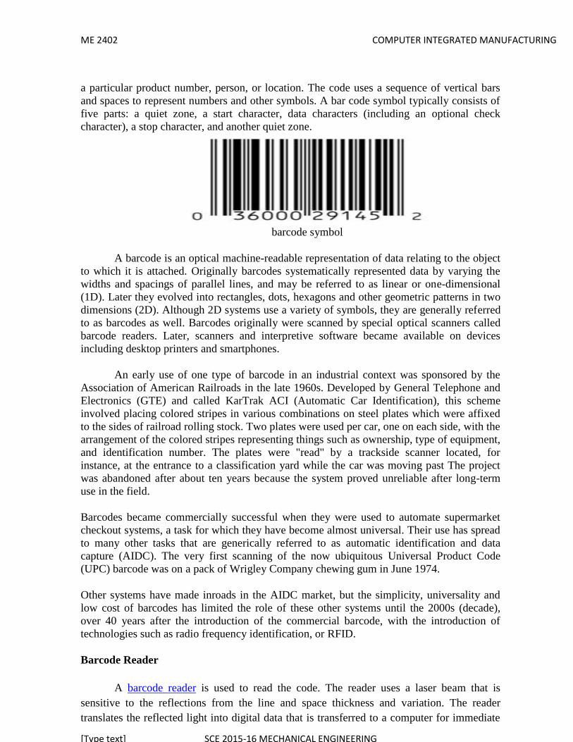
ME 2402 COMPUTER INTEGRATED MANUFACTURING
[Type text] SCE 2015-16 MECHANICAL ENGINEERING
a particular product number, person, or location. The code uses a sequence of vertical barsand spaces to represent numbers and other symbols. A bar code symbol typically consists offive parts: a quiet zone, a start character, data characters (including an optional checkcharacter), a stop character, and another quiet zone.
barcode symbol
A barcode is an optical machine-readable representation of data relating to the objectto which it is attached. Originally barcodes systematically represented data by varying thewidths and spacings of parallel lines, and may be referred to as linear or one-dimensional(1D). Later they evolved into rectangles, dots, hexagons and other geometric patterns in twodimensions (2D). Although 2D systems use a variety of symbols, they are generally referredto as barcodes as well. Barcodes originally were scanned by special optical scanners calledbarcode readers. Later, scanners and interpretive software became available on devicesincluding desktop printers and smartphones.
An early use of one type of barcode in an industrial context was sponsored by theAssociation of American Railroads in the late 1960s. Developed by General Telephone andElectronics (GTE) and called KarTrak ACI (Automatic Car Identification), this schemeinvolved placing colored stripes in various combinations on steel plates which were affixedto the sides of railroad rolling stock. Two plates were used per car, one on each side, with thearrangement of the colored stripes representing things such as ownership, type of equipment,and identification number. The plates were "read" by a trackside scanner located, forinstance, at the entrance to a classification yard while the car was moving past The projectwas abandoned after about ten years because the system proved unreliable after long-termuse in the field.
Barcodes became commercially successful when they were used to automate supermarketcheckout systems, a task for which they have become almost universal. Their use has spreadto many other tasks that are generically referred to as automatic identification and datacapture (AIDC). The very first scanning of the now ubiquitous Universal Product Code(UPC) barcode was on a pack of Wrigley Company chewing gum in June 1974.
Other systems have made inroads in the AIDC market, but the simplicity, universality andlow cost of barcodes has limited the role of these other systems until the 2000s (decade),over 40 years after the introduction of the commercial barcode, with the introduction oftechnologies such as radio frequency identification, or RFID.
Barcode Reader
A barcode reader is used to read the code. The reader uses a laser beam that issensitive to the reflections from the line and space thickness and variation. The readertranslates the reflected light into digital data that is transferred to a computer for immediate

ME 2402 COMPUTER INTEGRATED MANUFACTURING
[Type text] SCE 2015-16 MECHANICAL ENGINEERING
action or storage. Bar codes and readers are most often seen in supermarkets and retailstores, but a large number of different uses have been found for them. They are also used totake inventory in retail stores; to check out books from a library; to track manufacturing andshipping movement; to sign in on a job; to identify hospital patients; and to tabulate theresults of direct mail marketing returns.
Very small bar codes have been used to tag honey bees used in research. Readersmay be attached to a computer (as they often are in retail store settings) or separate andportable, in which case they store the data they read until it can be fed into a computer.
There is no one standard bar code; instead, there are several different bar codestandards called symbologies that serve different uses, industries, or geographic needs. Since1973, the Uniform Product Code (UPC), regulated by the Uniform Code Council, anindustry organization, has provided a standard bar code used by most retail stores. TheEuropean Article Numbering system (EAN), developed by Joe Woodland, the inventor ofthe first bar code system, allows for an extra pair of digits and is becoming widely used.POSTNET is the standard bar code used in the United States for ZIP codes in bulk mailing.The following table summarizes the most common bar code standards.
Barcode Scanning Technology
Scanning technology is constantly evolving and providing industries with morechoices in data capture solutions. Two competing data capture devices: the laser scanner andthe digital imager have many businesses facing a tough decision. Deciding which scanningtechnology is right for your application can be a difficult task. Knowing the advantages andapplications in which these two technologies are used is the first step to success.
The key to deciding between these two technologies is determining which fits therequirements and budget of your business most accurately.
2D Data Matrix Code
Both laser scanners and digital images are programmed to decode specificsymbologies, or the “language,” of barcodes. The symbology used in the application canhelp determine which scanning technology will provide the most benefit. The use of 2-dimensional (2D) symbologies is on the rise in many markets, making digital imagers a
ME 2402 COMPUTER INTEGRATED MANUFACTURING
[Type text] SCE 2015-16 MECHANICAL ENGINEERING
better choice. However, for applications that don’t require reading 2D barcodes, laserscanners are a cost-effective option.
UNIT – V – COMPUTER AIDED PROCESS PLANNINGAND CONTROL AND COMPUTER MONITORING.
Part - A (2 Marks)
1. Production Planning and controlProduction planning and control may be defined as the direction as the
direction and coordination of a firm’s material and physical facilities towards theattainment of pre specified Production of goods, with production efficiency.2. Production planning
Deciding which products to make, how many of each, and whenthey should be completed.
Planning the manpower and equipment resources needed toaccomplish the production plan.
Scheduling the production and delivery of the parts and products ;
3. Production controlProduction control is concerned with determining whether the necessary
resources to implement the production plan have been provided or not.4. Activities of production control.
Shop floor control; Inventory control; Manufacturing resource planning (MRP II); and Just-in-time manufacturing systems.
5. MRP - Function of MRPIt is a planning technique. It translates the master production schedule (MPS)
of end products into a detailed schedule for the raw materials and parts used in those endproducts.6. BOM
The bill of materials (BOM) designates what itemsand how many of each are used tomake up a specified final product.
7. Benefits of MRP

ME 2402 COMPUTER INTEGRATED MANUFACTURING
[Type text] SCE 2015-16 MECHANICAL ENGINEERING
The benefits of implementing MRP system are: Reduced inventory levels. Better Production scheduling Reduced production lead time. Better machine utilization. Improved product quality.
8. Material requirements planning (MRP)
It is a production planning and inventory control system used to managemanufacturing processes. Most MRP systems are software-based, while it is possible toconduct MRP by hand as well.
An MRP system is intended to simultaneously meet three objectives:
Ensure materials are available for production and products are available for deliveryto customers.
Maintain the lowest possible material and product levels in store Plan manufacturing activities, delivery schedules and purchasing activities.
9. Agile manufacturing
It is a term applied to an organization that has created the processes, tools, andtraining to enable it to respond quickly to customer needs and market changes while stillcontrolling costs and quality.
10. Inventory Control
It is the supervision of supply, storage and accessibility of items in order to ensure anadequate supply without excessive oversupply. It can also be referred as internal control -an accounting procedure or system designed to promote efficiency or assure theimplementation of a policy or safeguard assets or avoid fraud and error etc.
11.Inventory control may refer to:
In economics, the inventory control problem, which aims to reduce overhead costwithout hurting sales
In the field of loss prevention, systems designed to introduce technical barriers toshoplifting
12.Inventory

ME 2402 COMPUTER INTEGRATED MANUFACTURING
[Type text] SCE 2015-16 MECHANICAL ENGINEERING
Inventory or stock refers to the goods and materials that a business holds for theultimate purpose of resale (or repair).
Inventory management is a science primarily about specifying the shape and percentageof stocked goods. It is required at different locations within a facility or within manylocations of a supply network to precede the regular and planned course of production andstock of materials.
13.Lean manufacturing,
Lean manufacturing, Lean Enterprise, or lean production, often simply, "lean", is aproduction philosophy that considers the expenditure of resources in any aspect other thanthe direct creation of value for the end customer to be wasteful, and thus a target forelimination. Working from the perspective of the client who consumes a product or service,"value" is any action or process that a customer would be willing to pay for.
Basically, lean manufacturing technique consists of four steps. First step is to realizethat there are wastes in the system to be removed. Although this seems like a crazy idea, thisis the step which creates the requirement for the movement towards lean manufacturing.Many organizations do not realize that they have tons of hidden wastes with them. Thereforethey do not have the requirement to remove them from the system. So they will have theirproblems forever and they will try to find solutions for these problems forever.
14.Direct digital control (DDC)
It is the automated control of a condition or process by a digital device (computer).
A very early example of a DDC system meeting the above requirements wascompleted by the Australian business Midac in 1981-1982 using R-Tec Australian designedhardware.
15.Inventory Management;
Inventory management is a science primarily about specifying the shape andpercentage of stocked goods. It is required at different locations within a facility or withinmany locations of a supply network to precede the regular and planned course of productionand stock of materials.
Part - B ( 16 Marks)

ME 2402 COMPUTER INTEGRATED MANUFACTURING
[Type text] SCE 2015-16 MECHANICAL ENGINEERING
1.Explain the Inventory management in CIM?
Definition - Inventory
Inventory management is primarily about specifying the size and placement ofstocked goods. Inventory management is required at different locations within a facility orwithin multiple locations of a supply network to protect the regular and planned course ofproduction against the random disturbance of running out of materials or goods.
The scope of inventory management also concerns the fine lines betweenreplenishment lead time, carrying costs of inventory, asset management, inventoryforecasting, inventory valuation, inventory visibility, future inventory price forecasting,physical inventory, available physical space for inventory, quality management,replenishment, returns and defective goods and demand forecasting and also byreplenishment Or can be defined as the left out stock of any item used in an organization.inventory is liabilities of a business.
The overseeing and controlling of the ordering, storage and use of components that acompany will use in the production of the items it will sell as well as the overseeing andcontrolling of quantities of finished products for sale. A business's inventory is one of itsmajor assets and represents an investment that is tied up until the item is sold or used in theproduction of an item that is sold. It also costs money to store, track and insure inventory.Inventories that are mismanaged can create significant financial problems for a business,whether the mismanagement results in an inventory glut or an inventory shortage.
Inventory or stock refers to the goods and materials include that a business holds forthe ultimate purpose of resale (or repair).
Inventory management is a science primarily about specifying the shape and percentage ofstocked goods. It is required at different locations within a facility or within many locationsof a supply network to precede the regular and planned course of production and stock ofmaterials.
The scope of inventory management concerns the fine lines between replenishmentlead time, carrying costs of inventory, asset management, inventory forecasting, inventoryvaluation, inventory visibility, future inventory price forecasting, physical inventory,available physical space for inventory, quality management, replenishment, returns anddefective goods, and demand forecasting. Balancing these competing requirements leads tooptimal inventory levels, which is an ongoing process as the business needs shift and react tothe wider environment.

ME 2402 COMPUTER INTEGRATED MANUFACTURING
[Type text] SCE 2015-16 MECHANICAL ENGINEERING
Inventory management involves a retailer seeking to acquire and maintain a propermerchandise assortment while ordering, shipping, handling, and related costs are kept incheck. It also involves systems and processes that identify inventory requirements, settargets, provide replenishment techniques, report actual and projected inventory status andhandle all functions related to the tracking and management of material. This would includethe monitoring of material moved into and out of stockroom locations and the reconciling ofthe inventory balances. It also may include ABC analysis, lot tracking, cycle countingsupport, etc. Management of the inventories, with the primary objective ofdetermining/controlling stock levels within the physical distribution system, functions tobalance the need for product availability against the need for minimizing stock holding andhandling costs.
Definition - Inventory management
Inventory management is primarily about specifying the size and placement ofstocked goods. Inventory management is required at different locations within a facility orwithin multiple locations of a supply network to protect the regular and planned course ofproduction against the random disturbance of running out of materials or goods.
The scope of inventory management also concerns the fine lines betweenreplenishment lead time, carrying costs of inventory, asset management, inventoryforecasting, inventory valuation, inventory visibility, future inventory price forecasting,physical inventory, available physical space for inventory, quality management,replenishment, returns and defective goods and demand forecasting and also byreplenishment Or can be defined as the left out stock of any item used in an organization.inventory is liabilities of a business.
2.explain the Material requirements planning (MRP) in CIM?
It is a production planning, scheduling, and inventory control system used to managemanufacturing processes. Most MRP systems are software-based, while it is possible toconduct MRP by hand as well.
An MRP system is intended to simultaneously meet three objectives:
Ensure materials are available for production and products are available for deliveryto customers.
ME 2402 COMPUTER INTEGRATED MANUFACTURING
[Type text] SCE 2015-16 MECHANICAL ENGINEERING
Maintain the lowest possible material and product levels in store Plan manufacturing activities, delivery schedules and purchasing activities.
History Of MRP
Prior to MRP, and before computers dominated industry, Reorder point (ROP) /reorder-quantity (ROQ) type methods like EOQ (Economic Order Quantity) had been usedin manufacturing and inventory management.
In 1964, as a response to the Toyota Manufacturing Program, Joseph Orlickydeveloped Material Requirements Planning (MRP). The first company to use MRP wasBlack & Decker in 1964, with Dick Alban as project leader. Orlicky's book MaterialRequirements Planning has the subtitle The New Way of Life in Production and InventoryManagement (1975). By 1975, MRP was implemented in 700 companies. This number hadgrown to about 8,000 by 1981.
In 1983 Oliver Wight developed MRP into manufacturing resource planning (MRPII).[1] In the 1980s, Joe Orlicky's MRP evolved into Oliver Wight's manufacturing resourceplanning (MRP II) which brings master scheduling, rough-cut capacity planning, capacityrequirements planning, S&OP in 1983 and other concepts to classical MRP. By 1989, aboutone third of the software industry was MRP II software sold to American industry ($1.2billion worth of software).[2]
Functions of MRP;
The basic functions of an MRP system include: inventory control, bill of materialprocessing, and elementary scheduling. MRP helps organizations to maintain low inventorylevels. It is used to plan manufacturing, purchasing and delivering activities.
"Manufacturing organizations, whatever their products, face the same daily practicalproblem - that customers want products to be available in a shorter time than it takes to makethem. This means that some level of planning is required."
Companies need to control the types and quantities of materials they purchase, planwhich products are to be produced and in what quantities and ensure that they are able tomeet current and future customer demand, all at the lowest possible cost. Making a baddecision in any of these areas will make the company lose money. A few examples are givenbelow:
If a company purchases insufficient quantities of an item used in manufacturing (orthe wrong item) it may be unable to meet contract obligations to supply products ontime.

ME 2402 COMPUTER INTEGRATED MANUFACTURING
[Type text] SCE 2015-16 MECHANICAL ENGINEERING
If a company purchases excessive quantities of an item, money is wasted - the excessquantity ties up cash while it remains as stock and may never even be used at all.
Beginning production of an order at the wrong time can cause customer deadlines tobe missed.
MRP is a tool to deal with these problems. It provides answers for several questions:
What items are required? How many are required? When are they required?...
MRP can be applied both to items that are purchased from outside suppliers and to sub-assemblies, produced internally, that are components of more complex items.
3.Explain the Manufacturing Shop Floor Control
Definition
Shop floor control comprises the methods and systems used to prioritize, track, andreport against production orders and schedules. It includes the procedures used to evaluatecurrent resource status, labor, machine usage, and other information required to support theoverall planning, scheduling, and costing systems related to shop floor operation. Shop floorcontrol typically calculates work in process based on a percentage of completion for eachorder and operation that is useful in inventory valuations and materials planning.
Shop floor control is responsible for the detailed management of activities and the flowof materials inside the plant, including employees, materials, machines, and production time.Shop floor control activity typically begins after planning (e.g., with MRP, ERP); onceplanned, orders and purchase requisitions are created. Shop floor control attends to thefollowing functions (sequentially):
Planned orders Conversion of planned orders to process/production Production and process order scheduling Capacity requirements planning Material availability assessment Release of production/process orders Material withdrawals Order confirmations Goods receipt documentation Order settlement

ME 2402 COMPUTER INTEGRATED MANUFACTURING
[Type text] SCE 2015-16 MECHANICAL ENGINEERING
Shop floor control may also include identifying and assessing vulnerabilities and risks due tothe shop floor environment, employees, process, and the technologies employed at the shop-floor level. Based on the assessment of these factors, shop floor control initiates measures tokeep risk at an acceptable minimum level.
Best practices for shop floor control include:
Efficiently execute, prioritize, and release work orders to the shop floor with real-time status of progress and completion.
Deliver accurate and up-to-date information on materials consumption andavailability, which is essential for reliable inventory planning and costing.
Effectively execute change management processes to ensure that the proper revisionof products, bills of materials, and processes are always in place for production.
Automate shop floor equipment control and data collection to reduce human errorsand increase productivity.
Provide the correct manufacturing SOPs, technical drawings, and diagnostics to shopfloor operators to reinforce training and ensure proper processing.
Download setup programs directly to equipment based on product and processspecifications.
With fully interactive access to shop floor control software, supervisors can monitor shopactivities and make better decisions on the spot, especially using mobile computingequipment.
Shop Floor Control are methods and systems used to prioritize, track, and reportagainst production orders and schedules. They include the procedures used to evaluatecurrent resource status, and the update of labor, machine hour, and other associatedinformation as required to support the overall planning, scheduling, and costing systems.
4.Explain the Agile and Lean manufacturing in CIM?
Agile manufacturing is a term applied to an organization that has created theprocesses, tools, and training to enable it to respond quickly to customer needs and marketchanges while still controlling costs and quality.
An enabling factor in becoming an agile manufacturer has been the development ofmanufacturing support technology that allows the marketers, the designers and theproduction personnel to share a common database of parts and products, to share data onproduction capacities and problems — particularly where small initial problems may havelarger downstream effects. It is a general proposition of manufacturing that the cost ofcorrecting quality issues increases as the problem moves downstream, so that it is cheaper tocorrect quality problems at the earliest possible point in the process.
ME 2402 COMPUTER INTEGRATED MANUFACTURING
[Type text] SCE 2015-16 MECHANICAL ENGINEERING
Agile manufacturing is a term applied to an organization that has created theprocesses, tools, and training to enable it to respond quickly to customer needs and marketchanges while still controlling costs and quality.
An enabling factor in becoming an agile manufacturer has been the development ofmanufacturing support technology that allows the marketers, the designers and theproduction personnel to share a common database of parts and products, to share data onproduction capacities and problems — particularly where small initial problems may havelarger downstream effects.
It is a general proposition of manufacturing that the cost of correcting quality issuesincreases as the problem moves downstream, so that it is cheaper to correct quality problemsat the earliest possible point in the process. Agile manufacturing is seen as the next step afterLean manufacturing in the evolution of production methodology. The key differencebetween the two is like between a thin and an athletic person, agile being the latter. One canbe neither, one or both. In manufacturing theory, being both is often referred to as leagile.
According to Martin Christopher, when companies have to decide what to be, theyhave to look at the Customer Order Cycle (the time the customers are willing to wait) andthe leadtime for getting supplies. If the supplier has a short lead time, lean production ispossible. If the COC is short, agile production is beneficial.
Lean manufacturing or lean production, often simply "lean", is a systematicmethod for the elimination of waste ("Muda") within a manufacturing process. Lean alsotakes into account waste created through overburden ("Muri") and waste created throughunevenness in work loads ("Mura"). Working from the perspective of the client whoconsumes a product or service, "value" is any action or process that a customer would bewilling to pay for.
Essentially, lean is centered on making obvious what adds value by reducingeverything else. Lean manufacturing is a management philosophy derived mostly from theToyota Production System (TPS) (hence the term Toyotism is also prevalent) and identifiedas "lean" only in the 1990s TPS is renowned for its focus on reduction of the original Toyotaseven wastes to improve overall customer value, but there are varying perspectives on howthis is best achieved. The steady growth of Toyota, from a small company to the world'slargest automaker, has focused attention on how it has achieved this success.
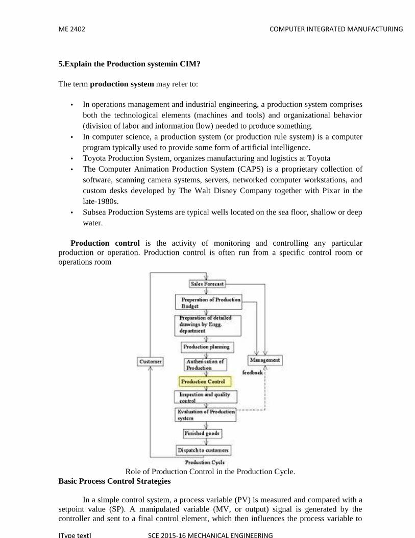
ME 2402 COMPUTER INTEGRATED MANUFACTURING
[Type text] SCE 2015-16 MECHANICAL ENGINEERING
5.Explain the Production systemin CIM?
The term production system may refer to:
In operations management and industrial engineering, a production system comprisesboth the technological elements (machines and tools) and organizational behavior(division of labor and information flow) needed to produce something.
In computer science, a production system (or production rule system) is a computerprogram typically used to provide some form of artificial intelligence.
Toyota Production System, organizes manufacturing and logistics at Toyota The Computer Animation Production System (CAPS) is a proprietary collection of
software, scanning camera systems, servers, networked computer workstations, andcustom desks developed by The Walt Disney Company together with Pixar in thelate-1980s.
Subsea Production Systems are typical wells located on the sea floor, shallow or deepwater.
Production control is the activity of monitoring and controlling any particularproduction or operation. Production control is often run from a specific control room oroperations room
Role of Production Control in the Production Cycle.Basic Process Control Strategies
In a simple control system, a process variable (PV) is measured and compared with asetpoint value (SP). A manipulated variable (MV, or output) signal is generated by thecontroller and sent to a final control element, which then influences the process variable to
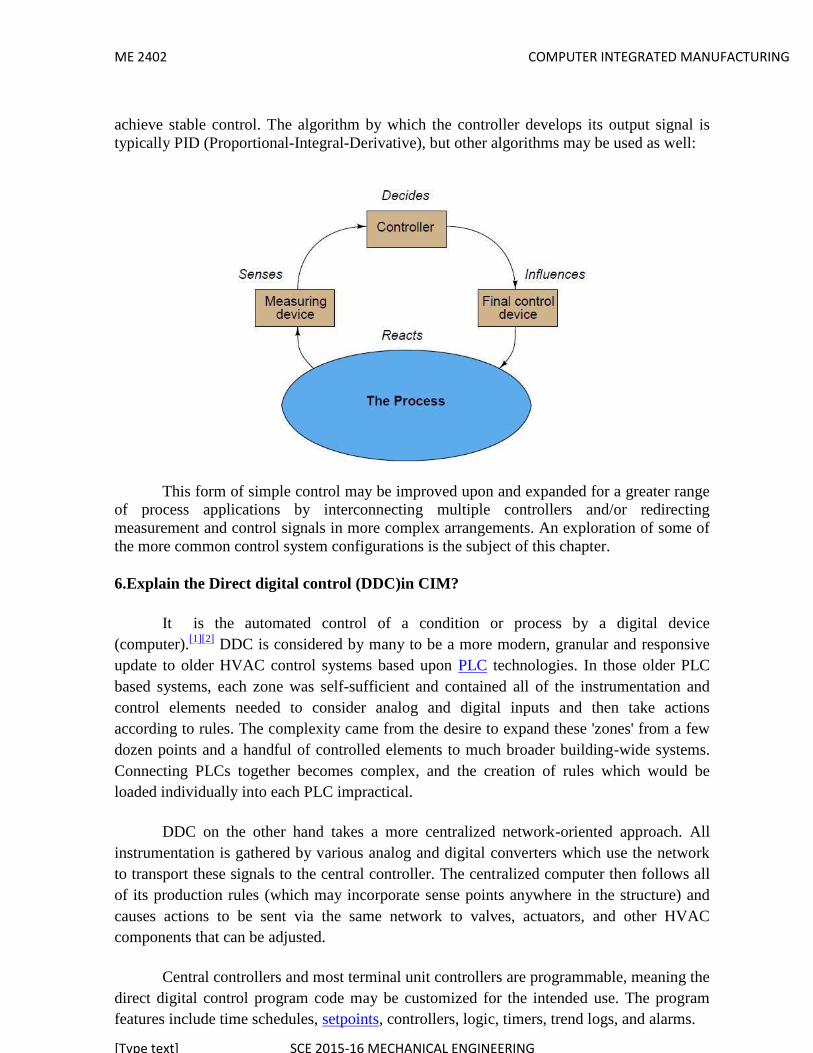
ME 2402 COMPUTER INTEGRATED MANUFACTURING
[Type text] SCE 2015-16 MECHANICAL ENGINEERING
achieve stable control. The algorithm by which the controller develops its output signal istypically PID (Proportional-Integral-Derivative), but other algorithms may be used as well:
This form of simple control may be improved upon and expanded for a greater rangeof process applications by interconnecting multiple controllers and/or redirectingmeasurement and control signals in more complex arrangements. An exploration of some ofthe more common control system configurations is the subject of this chapter.
6.Explain the Direct digital control (DDC)in CIM?
It is the automated control of a condition or process by a digital device(computer).[1][2] DDC is considered by many to be a more modern, granular and responsiveupdate to older HVAC control systems based upon PLC technologies. In those older PLCbased systems, each zone was self-sufficient and contained all of the instrumentation andcontrol elements needed to consider analog and digital inputs and then take actionsaccording to rules. The complexity came from the desire to expand these 'zones' from a fewdozen points and a handful of controlled elements to much broader building-wide systems.Connecting PLCs together becomes complex, and the creation of rules which would beloaded individually into each PLC impractical.
DDC on the other hand takes a more centralized network-oriented approach. Allinstrumentation is gathered by various analog and digital converters which use the networkto transport these signals to the central controller. The centralized computer then follows allof its production rules (which may incorporate sense points anywhere in the structure) andcauses actions to be sent via the same network to valves, actuators, and other HVACcomponents that can be adjusted.
Central controllers and most terminal unit controllers are programmable, meaning thedirect digital control program code may be customized for the intended use. The programfeatures include time schedules, setpoints, controllers, logic, timers, trend logs, and alarms.

ME 2402 COMPUTER INTEGRATED MANUFACTURING
[Type text] SCE 2015-16 MECHANICAL ENGINEERING
The unit controllers typically have analog and digital inputs, that allow measurementof the variable (temperature, humidity, or pressure) and analog and digital outputs for controlof the medium (hot/cold water and/or steam). Digital inputs are typically (dry) contacts froma control device, and analog inputs are typically a voltage or current measurement from avariable (temperature, humidity, velocity, or pressure) sensing device.
Digital outputs are typically relay contacts used to start and stop equipment, andanalog outputs are typically voltage or current signals to control the movement of themedium (air/water/steam) control devices. Usually abbreviated as "DDC".
*** END ***** ALL THE VERY BEST **