computer network for a company with remote branch offices · computer network for a company with...
TRANSCRIPT

Degree Project
Desislav Ivanov 2010-10-19 Subject: Computer Systems and Technologies Level: Bachelor Course code: 2DV00E
Computer network for a company with remote branch offices

i
School of Mathematics and Systems Engineering Reports from MSI
Computer network for a company with remote branch offices
Desislav Pavlov Ivanov

ii
Abstract
The purpose of this project was to design a network for a company with remote branch offices. The author has interest in network architectures and wished to gain improved knowledge of remote networks.
Comparative method was used in this project. Information was collected, analyzed, and choices were made to choose the right network design solutions for the goal of this project.
The designing of a reliable, scalable, and secure network is a complex task that requires knowledge and experience over the wide area of computer networking, including knowledge of network device configuration, network types, routing protocols, potential security threats and many more. In this project the main approaches in network design were covered, and some of them demonstrated. Demonstration network was developed using the Graphic Network Simulator (GNS) software for simulating network devices.
Keywords: network design, corporate network, network architecture, remote networks, branch network, enterprise network branch, branch architecture, remote access

iii
Contents 1 Introduction .............................................................................................................. 1
1.1 Problem Definition ........................................................................................... 1 1.2 Motivation ........................................................................................................ 1 1.3 Method .............................................................................................................. 1 1.4 Restrictions ....................................................................................................... 1 1.5 Structure of report ............................................................................................. 2
2 Theory ....................................................................................................................... 3 2.1 Company computer network with branches ..................................................... 3
2.1.1 Network Infrastructure and Architecture ...................................................... 3 2.1.2 Services ......................................................................................................... 7 2.1.3 Communication and integration ................................................................... 8 2.1.4 Authentication ............................................................................................ 18 2.1.5 Management ............................................................................................... 19 2.1.6 Security ....................................................................................................... 22 2.1.7 Solutions and examples .............................................................................. 25
2.2 Methodological aspects of the design ............................................................. 27 2.2.1 Top-down and bottom-up design approaches ............................................. 27 2.2.2 Modular design ........................................................................................... 27 2.2.3 Prepare, Plan, Design, Implement, Operate, Optimize (PPDIOO) Network Lifecycle Approach ................................................................................................ 30
2.3 Conclusion, Aims and Purposes ..................................................................... 32 3 Designing ................................................................................................................ 33
3.1 Company network with remote branch offices architecture, services and communication ........................................................................................................... 33
3.1.1 Architecture ................................................................................................ 33 3.1.2 Services ....................................................................................................... 38 3.1.3 Branch office connectivity, communication, and integration ..................... 39 3.1.4 Designing the enterprise Internet edge topology ........................................ 42
3.2 Organizing the remote branch offices ............................................................ 45 3.3 Analysis, evaluation and testing of the solution ............................................. 46
Results ............................................................................................................................ 50 4 Discussion on results .............................................................................................. 51
4.1 Conclusion ...................................................................................................... 51 4.2 Recommendations .......................................................................................... 51 4.3 Future work .................................................................................................... 51 References .................................................................................................................. 52
Appendix A .................................................................................................................... 54 Network documents and decisions ............................................................................. 54
Appendix B ..................................................................................................................... 60 Test results .................................................................................................................. 60

iv
List of abbreviations
• LAN – Local Area Network • MAN – Metropolitan Area Network • WAN – Wide Area Network • PSTN – Public Switched Telephone Network • DHCP – Dynamic Host Configuration Protocol • DNS – Domain Name System • AMANDA - Advanced Maryland Automatic Network Disk Archiver • ZRM – Zmanda Recovery Manager • LRS – Mandriva Linbox Rescue Server • VPN – Virtual Private Network • IPsec – Internet Protocol Security • SSL – Secure Sockets Layer • L2TP – Layer 2 Tunneling Protocol • PPTP – Point to Point Tunneling Protocol • OSI – Open System Interconnection • IP – Internet Protocol • IOS – Internetwork Operating System • PIX – Private Internet eXchange • ASA – Adaptive Security Appliance • TCP – Transmission Control Protocol • UDP – User Datagram Protocol • POP – Post Office Protocol • SSH – Secure Shell • PAP – Password Authentication Protocol • CHAP – Challenge-Handshake Authentication Protocol • MS-CHAP – Microsoft CHAP • MPPE – Microsoft Point-to-Point Encryption • NAT – Network Address Translation • PPP – Point to Point Protocol • GRE – Generic Routing Encapsulation • RADIUS – Remote Authentication Dial In User Service • AAA – Authentication, Authorization and Accounting • SNMP – Simple Network Management Protocol • DoS – Denial of service • ACL – Access Control List • DMZ – Demilitarized Zone • VoIP – Voice over IP • ISP – Internet Service Provider • PPPoE – Point to Point Protocol over Ethernet • IPS – Intrusion Prevention System • NAC – Network Admission Control • VLAN – Virtual LAN • QoS – Quality of Service • ATM – Asynchronous Transfer Mode • PPDIOO – Prepare, Plan, Design, Implement, Operate, and Optimize • SLA – Service Level Agreement • ACL – Access Control List • ISR – (Cisco’s) Integrated Services Router

v
List of figures and tables
Figures: Figure 2.1 Access/Distribution/Core model ..................................................................... 3Figure 2.2 Sample corporate network based on Access/Distribution/Core model ........... 4Figure 2.3 Different size branch offices ........................................................................... 5Figure 2.4 Typical Enterprise topology ............................................................................ 6Figure 2.5 Detailed Typical Enterprise Architecture ....................................................... 7Figure 2.6 WAN Connectivity Options ........................................................................... 9Figure 2.7 WAN aggregation topology ............................................................................ 9Figure 2.8 Performance metrics associated with the ISR series routers ......................... 13Figure 2.9 VPN device placed parallel to a firewall ....................................................... 13Figure 2.10 VPN device placed in the DMZ zone ......................................................... 14Figure 2.11 Integrated VPN and firewall device ............................................................ 14Figure 2.12 IPsec Phases in Cisco Devices ................................................................... 15Figure 2.13 SSL VPN Connection ................................................................................. 16Figure 2.14 L2TP over IPsec Negotiations .................................................................... 17Figure 2.15 PPTP Connection Negotiations ................................................................... 18Figure 2.16 Access management in an enterprise using RADIUS ................................. 19Figure 2.17 Configuration Mechanisms for Network Management ............................... 20Figure 2.18 Traffic Flows for In-Band Management ..................................................... 20Figure 2.19 Traffic Flows for Out-of-Band Management .............................................. 21Figure 2.20 A Combination of In-Band and Out-of-Band Management Traffic Flows 21Figure 2.21 Hierarchical Management Separates Management into Distinct Functions 22Figure 2.22 Single firewall DMZ Architecture .............................................................. 23Figure 2.23 Dual firewall DMZ Architecture ................................................................. 24Figure 2.24 ISR Small Branch Office Deployment ........................................................ 25Figure 2.25 Corporate branch offices ............................................................................. 26Figure 2.26 New York branch office .............................................................................. 27Figure 2.27 PPDIOO Network Lifecycle Approach ...................................................... 30Figure 2.28 Identifying Customer Requirements ........................................................... 31Figure 3.1 Remote Access Infrastructure ....................................................................... 34Figure 3.2 Placing the Remote Access Firewalls ........................................................... 34Figure 3.3 Border routers’ Internet connectivity ............................................................ 35Figure 3.4 Cisco ASR 1000 Services ............................................................................. 36Figure 3.5 Cisco ASR routing positioning ..................................................................... 36Figure 3.6 Campus network ............................................................................................ 43Figure 3.7 Campus network - DMZ and Internet edge ................................................... 44Figure 3.8 Campus network - Remote access VPN cluster ............................................ 45Figure 3.9 Branch Office Architecture ........................................................................... 46Figure 3.10 HSRP Testing Environment ........................................................................ 48Figure 3.11 Turning off HSRP Active router BR1 ......................................................... 49Figure 3.12 VPN test topology ....................................................................................... 49

vi
Tables: Table 2.1 Feature Requirements for WAN Aggregation Role ....................................... 10Table 2.2 Feature Requirements for WAN Aggregation Role (Cont.) ........................... 10Table 2.3 SLA Requirements ......................................................................................... 11Table 2.4 Details for Securing WAN traffic ................................................................... 11Table 2.5 Remote Access VPN Technologies Summary ............................................... 18Table 3.1 Cisco ASR 1000 series models ...................................................................... 36Table 3.2 Cisco ASA 5500 Series Model Comparison .................................................. 37Table 3.3 Private WAN vs. Site-to-site VPN ................................................................. 40Table 3.4 Cisco ISR Series Comparison ........................................................................ 41Table 3.5 ASA and ISR performance assessment .......................................................... 47

1
1 Introduction
Computer networks nowadays take a very significant place in business. It is very critical for business to use the latest technologies available because they provide enhanced security, increased storage capacity, high data transfer rates, real-time voice and video, and much more. Such benefits are strongly needed for a growing company or large enterprise. As a company grows it needs to have authorized representatives on different locations, which are usually spread in large geographical areas. The best solution is to invest for a branch office at the needed locations. This is very common scenario with companies developing software solutions; they either expand to a new location closer to potential customers or devour a small company with similar activities. Either way the headquarter office needs a reliable, secure, and fast connection to the offices at the remote locations.
The project is focused on the connection between the main office and the remote offices – branch offices, home workers, and mobile workers. In the first part of the project some different options for the communication between the corporate network and the remote networks are reviewed. In the second part, one of these options is chosen.
1.1 Problem Definition The final goal of this project is to show a design of a corporate computer communication network with a branched network of affiliate. The requirements we have on our solution are that the branched network of affiliates could be regionally-extended, international-extended or worldwide-extended with focus on the remote branch network implementation.
1.2 Motivation The motivation behind this project is based on some previous knowledge and experience in networking, network protocols, and configuration of Cisco network devices. What we hope to achieve at the end of the project is to improve our network design skills by doing research in that area and use the gathered knowledge for designing a network that will solve the problem.
1.3 Method We used comparative method in this project. In Chapter 2 we collect information about enterprises with remote branches network architectures and present different approaches. In Chapter 3 we analyze the collected solutions, compare them and decide which one to use for the goal of this project.
1.4 Restrictions Because of the background knowledge and experience we have with Cisco, and because Cisco is one of the biggest solution providers in networking (for example Juniper is another big network solution provider) and offers wide area of network solutions (from small/home office to complex corporate solutions) the project is based on Cisco strategies, advices, and equipment.
Network design by general is a very wide area and designing a corporate network with branches is complex task to accomplish. For this project it would be practically not feasible to analyze every single aspect of the network design for large scale company in details. The project focuses on the remote networks as branch offices with details for the functions, services, communication, integration, structure etc., on the background of a

2
corporate network. From the side of the corporate network will be discussed only the network elements needed for the remote access networks to operate.
1.5 Structure of report This report is organized into four chapters. In Chapter 1 the main goals of the project are pointed out. In Chapter 2 the main theoretical aspects of the work are discussed. It covers enterprise network architecture, remote branch network solutions, security, communication, and in the last section shows some sample network topologies. Chapter 3 is focused on designing a network solution for the goal of this project. Enterprise campus network topology is suggested as well as solution topology for the branch offices. Chapter 4 is summary of the work. Recommendations and conclusions are made and possible future work on the problem is suggested.

3
2 Theory
This chapter covers the basic theoretical knowledge that we would be needed in the designing process. The chapter is divided into four main sections. Section 2.1 contains information about company computer network with branches – architecture, services, communication and integration; section 2.2 discusses the methodological aspects of design – advices and steps we should follow when designing a network; and in section 2.3 are conclusions, aims and purposes.
2.1 Company computer network with branches
2.1.1 Network Infrastructure and Architecture In the development of our network there are several architectural models we can use as a starting point, either as a foundation of the network or build upon existing network. We will discuss three types of architectural models: o Topological models, which are often used as starting point in the development of
a network. These models are based on geographical or topological arrangement of network devices.
o Flow-based models, which are focused on and take advantage of a particular traffic flows
o Functional models – there models are based on one or more functions or features planned for in the network.
Usually the network is built using more than one of the architectural models.
Topological models Access/Distribution/Core and LAN/MAN/WAN models are most commonly used. We can also use them because they are simple and intuitive, and they are based on geographical or/and topological separation of networks. They also indicate the degree of hierarchy planned for the network (shown in Figure 2.1).
If we need we can also not use all of the levels of the models or if we need more we can expand them to show as many as we need. For example we can use the only LAN/WAN from the model as we assign campus, buildings, or even floors to the LAN. However, the Access/Distribution/Core model focuses on function instead of location. Both the LAN/MAN/WAN and Access/Distribution/Core models are used as starting points in the network architecture, as both are intuitive and easy to apply. They can be restrictive, however, in that they place strict boundaries between areas.
Figure 2.1 Access/Distribution/Core model [9]

4
Figure 2.2 shows a sample corporate network based on this topological model. On
the figure the different layers can be clearly seen.
Figure 2.2 Sample corporate network based on Access/Distribution/Core model [9]
Flow-based models The flow-based models we will discuss are peer-to-peer, client–server, hierarchical client–server, and distributed computing.
o Peer-to-peer – the users and applications in this model are consistent throughout the network, there are no obvious locations for architectural features. This pushes the functions, features, and services toward the edge of the network, close to users and their devices.
o Client–server – functions, features, and services are focused at server locations, the interfaces to client LANs, and client–server flows. The characteristics of the client–server model also apply to the hierarchical client– server architectural model. In addition to the functions, features, and services being focused at server locations and client–server flows, they are also focused at the server–server flows.
o Distributed-computing – in this model the data sources and sinks are obvious locations for architectural features.
Flow-based models, like the topological models, are intuitive and can be easy to apply. Since they are associated with flows, they should map well to any flow maps we created as part of the requirements analysis process. These models are fairly general, and they have to be modified to fit the specific requirements of a network.
Functional models These models focus on supporting particular function in the network, like service-provider, intranet/extranet, single-/multi-tiered performance, and end-to-end models. o The service-provider architectural model is based on service-provider functions,
focusing on privacy and security, service delivery to customers (users), and
5
billing. Many enterprise networks are evolving to this model, applying it across organizations, departments, and buildings.
o The intranet/extranet architectural model focuses on security and privacy, including the separation of users, devices, and applications based on secure access.
o The single-/multi-tiered performance architectural model focuses on identifying networks or parts of a network as having a single tier of performance, multiple tiers of performance, or having components of both.
o The end-to-end architectural model focuses on all components in the end-to-end path of a traffic flow.
Functional models are the most difficult to apply to a network, because we must understand where each function will be located. For example, to apply the end-to end model we first have to define where end-to-end is for each set of users, applications, or devices that will be a part of end-to-end. An advantage of using such models is that they are likely to be the most closely related to the requirements for the network.
Basic concepts of remote access networks The remote access network also had some basic components. From a topological level, a remote access network consists of three network segments: o The user’s network is the point of origin of access requests. It can be a branch
office network, or a home office consisting of a personal computer (PC) equipped with a modem.
o The corporate network is the destination of the user’s traffic. The wide area network (WAN) enables the user to access the corporate network. The WAN covers a large geographical area and can be a public switched telephone network (PSTN), the Internet, or a private data network. It provides the switching and/or routing function required to get a remote connection from the user’s network to the corporate network.
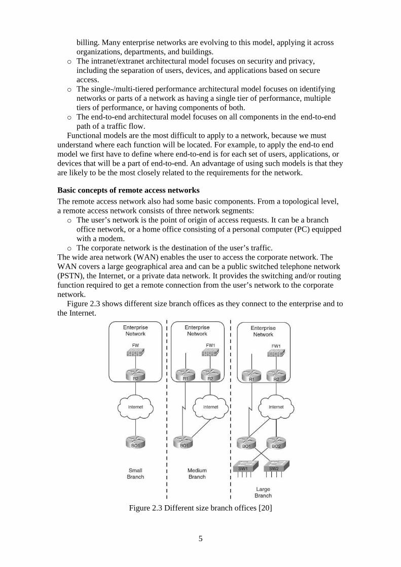
Figure 2.3 shows different size branch offices as they connect to the enterprise and to the Internet.
Figure 2.3 Different size branch offices [20]
6
We have labeled them as small, medium and large but this is a bit subjective. As the size of a branch increases, the number of routers (connections) increases, and also the issues number we have to consider are also increased. But anyhow, the figure gives us a clue of the two main implementation challenges we are facing for the branch design. First we must to provide features that would be needed for interaction with host in the public Internet, and second we must provide secure communication with the enterprise hosts. For the first category we should consider details for Internet access. For example, we should make DSL, or cable, or any other type of connection work. In the second category we must focus on options that allow an enterprise to prevent packets being read by attackers when they traverse the Internet. Such option is VPN as it allows the enterprise to trust packets coming from legitimate branch office.
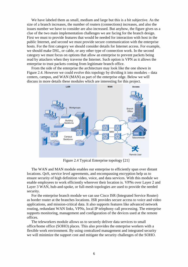
From the side of the enterprise the architecture may look like the one shown in Figure 2.4. However we could evolve this topology by dividing it into modules – data centers, campus, and WAN (MAN) as part of the enterprise edge. Below we will discuss in more details these modules which are interesting for this project.
Figure 2.4 Typical Enterprise topology [21]
The WAN and MAN module enables our enterprise to efficiently span over distant locations. QoS, service level agreements, and encompassing encryption help us to ensure security of high definition video, voice, and data services. With this module we enable employees to work efficiently wherever their location is. VPNs over Layer 2 and Layer 3 WAN, hub-and-spoke, or full-mesh topologies are used to provide the needed security.
For the enterprise branch module we can use Cisco ISR (Integrated Service Router) as border router at the branches locations. ISR provides secure access to voice and video applications, and mission-critical data. It also supports features like advanced network routing, redundant WAN links, VPNs, local IP telephony call processing. The enterprise supports monitoring, management and configuration of the devices used at the remote offices.
The teleworkers module allows us to securely deliver data services to small office/home office (SOHO) places. This also provides the enterprise workers with a flexible work environment. By using centralized management and integrated security we will minimize the support cost and mitigate the security challenges of the SOHO.

7
Teleworkers can gain access to authorized applications and services by logging in a secure always on VPN.
Figure 2.5 Detailed Typical Enterprise Architecture [21]
Figure 2.5 shows a more specific enterprise architecture structure. We are using it as a reference for a typical enterprise topology in which are revealed some of chosen solutions. As we can see the architecture is based on the Access/Distribution/Core topology. For WAN technology is chosen Frame Relay (FR). FR is a packet-switched WAN technology which is still in use in many enterprises. However, nowadays more and more used WAN technology is Multiprotocol Label Switching (MLPS). Service providers are deploying it very often as economical technology for carrying both circuit-switched and packet-switched network traffic, and MLPS can also operate over existing infrastructure (for example FR, ATM, IP, and Ethernet). Whereas FR is considered Layer 2 technology, MLPS is considered to be Layer 2.5 technology because it is situated between Layer 2 and Layer 3.
The figure also reveals part of the equipment needed for the branch office implementation. In the section for examples we will show more detailed topology for branch offices.
2.1.2 Services Services are typically installed on one or more network servers to provide shared resources to end users. In the section bellow we have pointed out the network services that are applied in maybe every network implementation.
Standard system services On a corporate network we usually use the following services: o DHCP (Dynamic Host Configuration Protocol) o DNS (Domain Name System) o File sharing o Authentication

8
o E-mail o Printing E-mail, printing and file sharing services require users to have permissions to access
them – security and access right needs to be configured. It is usually done easily by using directory service which is also a network service.
Also very important services of business nowadays are voice and video. We have to make sure to build a network that supports both voice and video with minimized jitter and delay.
Backup services There are also services for backup management, disaster recovery and monitoring tools. Doing backups is critical for companies and we must not forget it. There are many ways we can create backup. We can make backups daily, weekly, or monthly. It depends on the particular company’s policies. Some of the methods for backups include the following: o Recording of critical business data to CDs/DVDs, flash memory, memory sticks,
and others and storing them to secure storage place like safe with restricted access.
o Using a software based product to perform the backup and store the data in restricted access area on a file server, ftp server, or a network storage device
o If the backup is for remote user or remote branch office they could also sent the backup to the corporate network via secure connection where it will be stored on protected media.
If cost is more of a concern in selecting backup solution, our company should implement open source solutions. One of the most commonly used open source software products for doing backups is The Advanced Maryland Automatic Network Disk Archiver (AMANDA); from disaster recovery open source software products more often are used Zmanda Recovery Manager (ZRM), Mandriva Linbox Rescue Server (LRS), and Bacula. Each one of them provides us the ability to create and control created backups and restore the desired system.
Nevertheless, we will not discuss the network services used by enterprises in their networks in details because they are not the primary focus of this project.
2.1.3 Communication and integration An enterprise core network connects to the remote branch networks via WAN. We can choose from many existing options today for building the private WAN of an enterprise. These options include leased lines, Frame Relay, MPLS VPNs, and Metro Ethernet. Despite each is different in a way from the others they all have a common characteristic – they provide us with an inherently private path over which two of our enterprise routers can communicate with each other.
If we are looking for a cheaper solution of the problem or just do not want to implement costly private WAN, we can select the site-to-site VPN for interconnecting the enterprise network and the remote branch networks. The security in site-to-site VPN is provided by using IPsec and GRE. In the following sections we will examine private WANs and site-to-site VPNs in more details.
Private WAN We can use private WANs to connect and aggregate all of the corporate branches into the headend (or WAN core) router. From the side to the WAN cloud, the router interfaces support various physical transport methods, as shown in Figure 2.6. On the side to the campus core, typically is implemented Gigabit Ethernet (GE) or 10 Gigabit

9
Ethernet (10 GigE) that will be used for traffic between the campus core switches and the WAN.
Figure 2.6 WAN Connectivity Options [19]
We should also consider Metro Ethernet as main method for aggregating sites located at given geographical area. It scales also very well with trivial Gigabit Ethernet and 10 Gigabit Ethernet and is supposed to scale even more with the fairly new standards for 40 and 100 Gbps P802.3ba..
Figure 2.7 WAN aggregation topology [19]
The most common way we can use for interfacing with the WAN cloud is leased lines. Nowadays Ethernet is more often the preferred solution and it is replacing the costly leased lines. Usually the functions for IPsec tunnel termination and firewall are not deployed on the WAN edge router. Usually the classical hub-and-spoke design with

10
traditional Layer 2 connectivity is used. Figure 2.7 shows a basic private WAN topology with branches aggregation
In order to choose a router serving as the WAN aggregation platform we must outline basic requirements for the needed supported features (shown in Table 2.1 and Table 2.2). Based on how large the branch concentration is we may think of scale and performance for these services. It is good practice to choose a platform with separated control, data, and input/output plane.
Table 2.1 Feature Requirements for WAN Aggregation Role [19]
Table 2.2 Feature Requirements for WAN Aggregation Role (Cont.) [19]

11
We will also have to install SLA (Service Level Agreements). Table 2.3 outlines the typical SLA requirements for converged WAN for voice, video, and types of data traffic we should meet.
Table 2.3 SLA Requirements [19]
We must also not forget the security the WAN. The traditional WANs (for example those based on Frame Relay) are assumed to be inherently secure but this is not completely true because SP (service providers) use shared physical infrastructure to carry this traffic.
Table 2.4 Details for Securing WAN traffic [19]

12
We can choose to use MPLS VPN in which the traffic is isolated by the Virtual Routing/Forwarding (VRF) labels and instances. But MPLS still shares the same physical infrastructure when passing the SP cloud. Common practice that we can also follow is to add encryption to achieve confidentiality. Table 2.4 shows the commonly used technologies to secure the WAN traffic. We must note that in most cases the transport medium for secure connectivity is the public Internet.
Site-to-Site VPN As alternative to private WAN infrastructure we might use site-to-site VPNs to connect to branch offices. For VPNs we place the same requirements as for WAN – including high reliability, scalability, support multiple protocols, but we meet these requirements in a cost-effective manner with greater flexibility. Site-to-Site VPNs use as transport technology public Internet or service provider IP networks, by applying tunneling and encryption for achieving data privacy.
We can use site-to-site VPNs to replace the costly WAN service or we can use it as backup and recovery in case of disaster: o WAN Replacement IPsec is able to provide cost-effective replacement for WAN infrastructure. We would have to pay less for a relatively high bandwidth IP connection than for existing or upgraded WAN circuits. We can use IPsec VPNs to connect the remote branches, teleworkers, and mobile users to the main resources in the campus network. Site-to-Site VPN has four key components:
• Headend VPN device – serves as VPN headend termination device at the central campus
• VPN access device – serves as VPN branch-end termination device at branch office locations
• IPsec and GRE (Generic Routing Encapsulation) tunnels - Interconnect the headend and branch-end devices in the VPN
• Internet services from ISPs – serve as the WAN interconnection medium o WAN Backup We can also use IPsec VPNs for backing up an operating WAN. In that case when the primary network connection is malfunctioning, our branch offices can rely on Internet VPN connectivity while the primary connection is fixed. Using IPsec VPN over a high-speed ISP connection, broadband cable, or DSL access can provide us with cost-effective secondary connection to remote offices. The maximum speed at which IPsec VPN can operate is determined by the overall physical interface connection speeds of both corporate and branch routers, because usually an IPsec VPN connection does not have bandwidth associated with it.
We can use the Cisco ISR (Integrated Services Routers) as end routers for the site-to-site VPN connection. An ISR supports high-performance security features, rich VPN features with advanced firewall, and intrusion prevention. It also has extensive IOS software capabilities including QoS, multicast, multiprotocol, and advanced routing support. Figure 2.8 shows some best-case performance measures for individual security features but the performance numbers may differ in different production environments.

13
Figure 2.8 Performance metrics associated with the ISR series routers [9]
There are several strategies for placing the VPN devices among which we can choose. We will go through them with details for advantages and disadvantages:
o We can place VPN device parallel to a firewall (Shown in Figure 2.9).
Figure 2.9 VPN device placed parallel to a firewall [9]
The advantages in placing the VPN device parallel to the firewall are: • Deployment is simplified because we do not need to change firewall
addressing • High scalability because we can deploy multiple VPN devices parallel to the
firewall The drawbacks in placing the VPN device parallel to the firewall are:
• IPsec decrypted traffic is not inspected by the firewall. This is a major concern if the passing traffic is not subject to a stateful inspection
• We do not have implemented centralized point of logging or content inspection

14
o Figure 2.10 shows that we can place a VPN device in the demilitarized zone (DMZ)
Figure 2.10 VPN device placed in the DMZ zone [9]
The advantages for this design scenario are: • The firewall can statefully inspect the decrypted VPN traffic. • This design offers moderate-to-high scalability by adding additional VPN
devices. We can migrate to this design relatively easy by adding a LAN interface to firewall.
The disadvantages here are: • The configuration has increased complexity because we will need additional
configuration on the firewall to support the additional interfaces. The firewall must support policy routing to differentiate VPN versus non-VPN traffic.
• The firewall may set bandwidth restrictions on groups of VPN devices. o Figure 2.11 shows the scenario if we use an integrated VPN and firewall device.
Figure 2.11 Integrated VPN and firewall device [9]
If we choose this design we will meet the following advantages: • The firewall can statefully inspect the decrypted VPN traffic. • We can easily manage this design with the same or fewer devices to support.
The disadvantages we will have are: • Scalability can be trouble because a single device must scale to meet the
performance requirements of multiple connections • We apply the configurations to one device which will increase the
configuration complexity Site-to-site VPN has many benefits. Some of them are: o VPN is always on which means always connected

15
o It costs less than the private WAN o Provides secure connection by encryption VPN itself is divided into sub technologies - IPsec, SSL VPN, L2TP, L2TP over
IPsec, PPTP.
IPsec IPsec is probably the most widely used VPN technology. IPsec provides data integrity and ensures that packets were not modified during the transmission, provides packet authentication to verify that packets are coming from valid source, and encrypts data to assure confidentiality. The protection IPsec provides is at the IP level (Layer 3 OSI model). Cisco has also developed IPsec solutions for remote access. Figure 2.12 shows the phases a Cisco device goes through in order to establish IPsec connection.
Figure 2.12 IPsec Phases in Cisco Devices [2]
There are two different ways we can use IPsec solutions on Cisco devices: 1. Software based – To use this solution we must install a software-based VPN client
on end workstations. If the company’s policies do not allow installation of third party software we should use L2TP over IPsec. On the other machine used as VPN server we should install Cisco IPsec gateway. The software-based Cisco client will be free of charge as long as we have a valid service contract for using the Cisco IPsec gateway.
2. Hardware based – Cisco hardware-based VPN is supported on the following platforms:
• Cisco IOS router • Cisco PIX firewall • Cisco ASA 5505 and newer versions • Cisco VPN 3002 and newer hardware client
A SOHO router can also serve as VPN client and initiate a VNP connection on behalf of the host connected to it.
SSL VPN That a VPN technology that acts at the Application layer of the OSI model and proves secure connectivity to the corporate office resources through the use of web browser or dedicated client. The great advantage of SSL VPN comes from the fact that SSL is implemented and available in all web browsers. We can use SSL VPN from a kiosk or public networks like cafes, airports and many others. SSL VPN can also be customized so it can meet our company’s requirements. It is also using a cost-effective and flexible method but still providing strong data confidentiality.

16
Figure 2.13 SSL VPN Connection [2]
Cisco has improved SSL VPN so it can provide many ways of usage including the following: o Clientless mode – we can connect to the corporate resources, specifically to web
and e-mail servers, without the need of any clients of applets. o Thin client mode – we have access to most of the TCP-based protocols – SMTP,
POP, SSH, and Telnet by loading a Java applet on the client workstation o Full mode – we have full access to the corporate resources as if we were directly
connected to the network. To use this mode we must install dynamically downloadable SSL VPN client
Layer 2 Tunneling Protocol – L2TP This protocol is combination between Cisco Layer 2 Forwarding protocol and PPTP from Microsoft. It uses registered UDP port 1701 for both tunnel negotiations process and data encapsulation and uses PPP to package the data. If we are using L2F or PPTP technologies we could easily replace them with L2TP. There are two models in which L2TP is most generally deployed: o Voluntary tunnel model – this works more similarly to PPTP o Compulsory tunnel incoming call – this works more similarly to L2F L2TP is able to use several authentication protocols as Password Authentication
Protocol (PAP), Challenge-Handshake Authentication Protocol (CHAP), Microsoft CHAP (MS-CHAP). The data confidentiality can be provided using 40-bit or 128-bit encryption Microsoft Point-to-Point Encryption (MPPE) but it is also is recommended to add IPsec encryption to L2TP.
L2TP over IPsec Because L2TP fails to provide strong data confidentiality L2TP implementations are using IPsec to provide security. In L2TP over IPsec there are seven steps in order the user workstation and the office gateway to communicate (shown in Figure 2.14).

17
Figure 2.14 L2TP over IPsec Negotiations [2]
o First step is optional if our workstation is connected to Internet and can generate traffic. Otherwise, we must establish PPP session to the service provider access router to receive an IP address
o In the second step we execute the L2TP client that is configured to use IPsec for data security
o Then our workstation initiates and negotiates a session and a secure channel for exchanging keys.
o After successfully establishing Phase 1, we establishe two secure channels for data encryption and authentication. The data channels are set up to encrypt L2TP traffic that is destined to UDP port 1701.
o After IPsec is established, we initiate an L2TP session within IPsec. o Then our authentication credentials are used to validate the L2TP session. Any
PPP or L2TP attributes are negotiated after successfully authenticating. o After the L2TP session is established, our workstation sends data traffic that is
encapsulated within L2TP. The L2TP packets are encrypted by IPsec and then sent out to the other end of the tunnel over the Internet.
If we have a firewall between the L2TP over IPsec client and home gateway, we need to allow IP protocol 50 (ESP) and UDP port 500 to pass through. L2TP packets (UDP port 1701) are encapsulated within ESP. Some L2TP over IPsec vendors allow NAT transparency (NAT-T) by encapsulating traffic into UDP port 4500.
Point-to-Point Tunneling Protocol – PPTP PPTP servers as client-server network protocol that remote users can use to gain access to network resources over the Internet. PPTP uses PPP to encapsulate package data and then wraps the data within IP packets.
To initiate a connection to the PPTP gateway the client uses TCP port 1723. The user is afterwards asked for authentications credentials. If authentication is successful the user is negotiating more parameters needed to establish the link – compression, encryption, and the client uses GRE to encapsulate data packets and transmits them to

18
the gateway through an insecure link. After encapsulating the packets the gateway puts them on the private network. Figure 2.15 shows this process.
Figure 2.15 PPTP Connection Negotiations [2]
But PPTP is not widely used as remote technology because of security drawbacks in its protocol implementation.
When selecting a remote access technology we must do it according to the security policy of our enterprise. Table 2.5 gives us a summary of the VPN technologies.
Table 2.5 Remote Access VPN Technologies Summary [2]
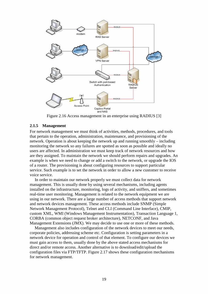
2.1.4 Authentication An enterprise also needs an authentication services – one or more, so remote users can authenticate theirselves and gain access to needed network resources. RADIUS is such server. RADIUS stands for Remote Authentication Dial In User Service. It provides centralized Authentication, Authorization and Accounting (AAA) management for computers to connect and use network resources.
RADIUS is a client/server protocol that runs at the Application layer. It uses UDP as transport protocol. All gateways that control access to the network like Remote Access Server, the Virtual Private Network server, the Network switch with port-based authentication, and the Network Access Server, have installed RADIUS component that communicates with the RADIUS server. Usually the RADIUS server is installed on UNIX based or Windows NT based machine and runs as background process. The main functions of the RADIUS server are:
o to authenticate users or devices before granting them access to our network o to authorize those users or devices for certain network services o to account for usage of those services
Figure 2.16 shows a typical scenario for using RADIUS server for access management.
19
Figure 2.16 Access management in an enterprise using RADIUS [3]
2.1.5 Management For network management we must think of activities, methods, procedures, and tools that pertain to the operation, administration, maintenance, and provisioning of the network. Operation is about keeping the network up and running smoothly – including monitoring the network so any failures are spotted as soon as possible and ideally no users are affected. In administration we must keep track of network resources and how are they assigned. To maintain the network we should perform repairs and upgrades. An example is when we need to change or add a switch to the network, or upgrade the IOS of a router. The provisioning is about configuring resources to support particular service. Such example is to set the network in order to allow a new customer to receive voice service.
In order to maintain our network properly we must collect data for network management. This is usually done by using several mechanisms, including agents installed on the infrastructure, monitoring, logs of activity, and sniffers, and sometimes real-time user monitoring. Management is related to the network equipment we are using in our network. There are a large number of access methods that support network and network devices management. These access methods include SNMP (Simple Network Management Protocol), Telnet and CLI (Command Line Interface), CMIP, custom XML, WMI (Windows Management Instrumentation), Transaction Language 1, CORBA (common object request broker architecture), NETCONF, and Java Management Extensions (JMX). We may decide to use one or more of these methods.
Management also includes configuration of the network devices to meet our needs, corporate policies, addressing scheme etc. Configuration is setting parameters in a network device for operation and control of that element. To configure our devices we must gain access to them, usually done by the above stated access mechanisms for direct and/or remote access. Another alternative is to download/edit/upload the configuration files via FTP/TFTP. Figure 2.17 shows these configuration mechanisms for network management.

20
Figure 2.17 Configuration Mechanisms for Network Management [1]
In order to keep our network up and running we must use monitoring tools. Monitoring tools include utilities such as ping, Traceroute, and TCPdump, while direct-access mechanisms include telnet, FTP, TFTP, and connections via a console port. What monitoring tool we will use is important but what matters more is important events notifications to be displayed in real time. For example when the delay of a connection crosses a set threshold, should be displayed event notification in real time. Last but not least it is important to collect the data produced by the monitoring. This data is called management data. Most commonly data is collected by a polling (actively probing network devices for management data) process. actively probing network devices for management data or monitoring involving a proxy service or network management protocol (like SNMP). At some point during data collection process some or all of the data is saved to a permanent (or semi-permanent) media or system. We could also divide this part of the process into multiple steps: o Primary storage – stage the data for short periods of time, which could be
performed at the network management server o Secondary storage – We have collected data from multiple primary storage sites
and aggregate the data at a storage server for the network o Tertiary storage – This is the most permanent and storage within the network. Depending on the physical location of our management equipment there are several
types of management – in-band and out-of-band management; centralized, distributed, and hierarchical management.
In-band and out-of-band management If we choose in band management the flow of traffic for network management will use the same routes as user traffic and their applications. This simplifies the network architecture because the same network paths can be used for both types of data. Figure 2.18 shows the traffic flow for in-band management.
Figure 2.18 Traffic Flows for In-Band Management [1]

21
Disadvantage is that management traffic can be affected by the same problems that affect user traffic and thus when the network management is most needed, it couldn’t be available.
In out-of-band management there are different paths for management traffic and for user traffic. This management gives us the advantage to continue monitoring the network even in the event of network failure. Figure 2.19 shows that usually out-of-band management is provided via another network, old telephone system (POTS) or frame-relay.
Figure 2.19 Traffic Flows for Out-of-Band Management [1]
A disadvantage of this management model is that it adds complexity and expense since we need another network for network management.
We could also use a combination of both for optimal management. We will use the in-band management when the network is operational and the out-of-band when the user network is not functional. Figure 2.20 shows the combination of in-band and out-of-band management traffic.
Figure 2.20 A Combination of In-Band and Out-of-Band Management Traffic Flows [1]
Centralized, distributed, and hierarchical management In centralized management we will need only one machine. All the management data like pings, traceroutes, SNMP etc, will radiate from a single management system, which is usually large. The obvious benefit is that since we will use a single system that will save us cost and simplify the architecture. The disadvantage is also obvious. This single system is a single point of failure.
The distributed management is when we are using multiple separate components to manage the network. These components are strategically placed in the network. The advantages of distributed management are that it provides redundant monitoring and since there are more management devices in the network the management traffic across

22
the network is reduced. A drawback is that the use of more devices will increase the cost.
The hierarchical management is when we decide to separate management functions and place them on different devices. This is hierarchical because when we separate the functions, we can consider each of them as separate layer that communicates in a client-server fashion. An advantage is we use this management type is that we can make every component redundant, independently from other components. A trade-off in hierarchical management is the cost, complexity, and overhead of having several management components on our network. Figure 2.21 shows a sample hierarchical management structure.
Figure 2.21 Hierarchical Management Separates Management into Distinct Functions
[1]
2.1.6 Security To design a completely secure enterprise network is nearly impossible. In such large scale network as an enterprise network there are many ways someone can breach the defenses and harm our network. Some of the threats, but surely not all, are listed below: o Unauthorized access to data, services, software, or hardware o Unauthorized disclosure of information o Denial of service (DoS) o Theft of data, services, software, or hardware o Corruption of data, services, software, or hardware o Viruses, worms, Trojan horses o Physical damage To deal with these threats and block them we must apply some privacy policies and
procedures. Our enterprise may decide to block all traffic from the inside networks to particular sites, for example youtube, external e-mails, torrent trackers etc. A common approach is to deny all traffic and explicitly allow just a list of specific routes. This is from our point of view as administrators. Users’ point of view is the opposite – allow everything and deny specific routes after that. By implementing so strict security policy we must have a thorough knowledge and understanding of user, applications, devices, and network requirements since these are very specific to be allowed and accepted. This can be done by implementing ACLs (access control list), firewalls, or any blocking software or hardware product.
In our enterprise we can also implement demilitarized zone (DMZ). The main idea of the DMZ is to add more security to an organization’s internal network. In the DMZ

23
zone we can expose our enterprise external devices to a large untrusted network which is usually the Internet. This way any potential attacker has only access to the devices in the DMZ zone and he has no visibility and access to our internal vulnerable network and devices. Usually to a DMZ zone can and is advised to be placed any service is being used from users from an outside network. The most common services are e-mail, web, proxy, reverse proxy, FTP servers, VoIP servers. Sometimes adding these services to the DMZ zone is not enough and additional steps must be taken to provide security: o Web servers – A web server in order to provide some specialized services may
need to communicate with an internal database. The database server contains vulnerable information and is not accessible from external networks. Database server should not be in DMZ zone. It is not very wise to allow the external web server to communicate directly with the database server. Instead, we can apply and use a application firewall which will act as a medium for the communication between the two servers. Although this is complicated, it will increase our security
o E-mail servers – To add the email server in the DMZ zone is a very poor idea. E-mail should be stored on internal e-mail server which will be placed in a hidden area inside the DMZ zone, thus protecting it from external access. It also not wise to place the e-mail server on the LAN. First this reduces performance, and second although the mail server is protected against external attacks, it is not protected from internal attacks like sniffing and spoofing. We should have an email server inside the DMZ zone and a secure internal mail server. The mail server from inside the DMZ should pass the incoming mails to the internal servers and the internal servers should pass the outgoing mails to the external (placed in the DMZ zone) servers.
There are a lot of ways to design network with DMZ zones but there are two most basic methods to do that – a single firewall architecture (Figure 2.22) and dual firewalls architecture (Figure 2.23).
Figure 2.22 Single firewall DMZ Architecture [13]

24
Figure 2.23 Dual firewall DMZ Architecture [13]
o In Figure 2.22 the firewall must have three interfaces. On the first interface is formed the external network – from ISP to firewall, on the second is formed the internal network, and on the third interface is formed the DMZ zone. But implementing this architecture the firewall becomes a single point of failure. Furthermore, it must be able to handle all the traffic destined to the DMZ zone and all the traffic destined to ISP.
o The architecture in Figure 2.23 represents a more secure approach. The first firewall (the right one) will be responsible for allowing traffic destined to the DMZ zone only. This firewall is also called “front-end” firewall. The second firewall must be configured to allow only traffic from the DMZ zone to the internal network. This firewall is called “back-end” firewall. The first firewall also has to handle a larger amount of traffic. Sometimes it is recommended to use firewall from different vendors because if an attacker somehow breaks through the first one, it will take more time to break through the second since it is made by another vendor. This technique is called “defense in depth” or “security through obscurity”. Of course this solution is more expensive than the first.
In the internal network is good idea to implement Network Address Translation (NAT) since the private address space is not propagated through the Internet. This additionally enhances security.
If we assume the internal network for secured it is time to secure the remote access connections as well. Maybe the most critical point of remote access is the authentication process. We can accomplish remote users’ authentication by applying a combination of PPP, PPPoE, CHAP. PAP, and RADIUS protocols. There are also other authentication mechanisms at the remote access network that include tokens, smart cards, digital certificates, and callback. VPN and SSL or other tunnels are also part of the remote access network.
SSL VPN is a potential entry point for security threads. SSL VPN does provide a lot of benefits to business but it is also putting in additional security challenges unlike others VPN remote access technologies. This is so because SSL VPN supports users from places not protected by the corporate laws and policies. Places like kiosk PC, internet cafes, etc. The connection is secure but if the SSL VPV users sing in from an infected machine they will most likely become a source for spreading viruses, worms, Trojan horses into the corporate network. In general, if we want to deal with uncontrolled end stations, we will face increased security risk.
Network Admission Control (NAC) – NAC is technology that addresses security compliance enforcement issues. The basic idea is to check and make sure that the

25
endpoints are compliant with corporate security policies – have proper antivirus software and Windows patching level, before the network devices grant users access to network resources.
2.1.7 Solutions and examples
Small branch office implementation with Cisco ISR Figure 2.24 represents an enterprise small branch office implementation with Cisco 890 series Integrated Service Router. The exact model of the ISR router is 892. It combines Internet access, wireless services, and extensive security in a single device that is easy to deploy and manage.
This ISR model also provides solutions for secure data and voice communications to the branch office; “High performance for secure broadband and Metro Ethernet access with concurrent services for enterprise small branch offices; Business continuity and WAN diversity with redundant WAN links: Fast Ethernet, V.92, and ISDN Basic Rate Interface (BRI)” [22]
Figure 2.24 ISR Small Branch Office Deployment [22]
We can use this model for site-to-site VPNs and remote access VPNs. The ISR supports VPN technologies, as IPsec, VPN (3DES or AES encryption, both are supported), Dynamic Multipoint VPN (DMVPN), and SSL VPN. With his 8-port 10/100 Fast Ethernet managed switch with VLAN support, wireless LAN (WLAN) and support for Power over Ethernet (PoE) with 4 available ports, is a economical solution for a small office as it can serve as router, switch and access point simultaneously.
As we can see at the side of the enterprise network as headend router are suggested two models – Cisco 2800 or Cisco 3800. They are both ISR routers from higher class that is suitable for enterprise networks. Cisco recommends the 2800 series for small and medium sized business while the 3800 series are recommended for medium to large enterprises and branches. More information about them is available at respectively for 2800 series at [36] and about 3800 series at [37].
Even though, Figure 2.24 does not show any details about the IP addressing scheme or more details about the enterprise topology, it gives us a decent cost-effective solution for a small branch office.
For more information regarding Cisco 892 series and including price is available at reference [22]. There we can also find information about other Cisco products, as catalyst switches, access points, etc. We can also refer to Integrated Service Routers section at official Cisco web site located at [38]

26
Implementation of small to medium secure corporate network with branches based on Cisco ASA, reviewed in [23]
Figure 2.25 Corporate branch offices [23]
Figure 2.25 shows that Cisco ASA series 5500 are applied at each of the remote offices. Each of the ASA is connected to Cisco IOS router to provide connectivity to the Internet. From the internal side of the network the ASAs are connected to catalyst switches for internal user connectivity.
Because of company’s security policies the branch offices are allowed to connect to the Internet only through TCP ports 80 (www) and 443 (SSL). The following business models are applied: o “The use of a third-party application that uses TCP ports 8912 and 8913. Client
machines from users at remote locations will access this third-party application server over the site-to-site VPN tunnel to SecureMe's regional site in Washington.
o Users access their e-mail (Simple Mail Transfer Protocol [SMTP], Post Office Protocol [POP], and Internet Message Access Protocol [IMAP]) from an e-mail server in Washington over the VPN tunnel.
o DNS is allowed for name resolution.” The administrators at the central site are using an application to remotely control (including software installation – operating system patches, antivirus updates, etc.) user workstations at remote branch offices. This application uses TCP port 7788 and it needs to be allowed on the ASA appliance. Figure 2.26 shows more detailed topology of the New York branch office that accommodates the above listed requirements. Topology of the other branch offices will be the same except the IP addressing scheme.

27
Figure 2.26 New York branch office [23]
The configuration of the New York branch office is listed in Appendix A.1. More information about Cisco ASA 5500 series is available at [39].
2.2 Methodological aspects of the design Designing a corporate network or even a single fragment from it (like the edge network) is complex task. Because of that we need to follow a proved approach, in the design process, which will facilitate our work as much as possible. Now we will review possible design guides in order to select one we will use in the design of our network.
2.2.1 Top-down and bottom-up design approaches For top-down design approach we must first consider the requirements, with applications and network solutions that we want running in our network. This approach facilitates the design process by dividing it into smaller and easy manageable steps. Top-down approach also helps us to clarify the design goals and start the design from the perspective of the required applications and solutions. Structured top-down approach focuses on dividing design process into related, less complex elements:
o We should identify the needed applications to support the user's requirements. o We should identify the logical connectivity requirements of the applications,
with a focus on the necessary network solutions and the supporting network services. Such infrastructure services include voice, content networking, and storage networking, availability, management, security, and QoS.
o We should split the network functionally to develop the network infrastructure and hierarchy requirements.
o We should design each structured element separately but in relation to other elements. Network infrastructure and infrastructure services design are tightly connected, because both are bound to the same logical, physical, and layered models.
For bottom-up approach we should first select devices, features, and so on, and after that try to fit the applications in that network. This approach can force us to redesign if the applications are not accommodated properly. It could also result in increased costs because we are including features or devices that we do not need and we would exclude them after completing network requirements analysis.
2.2.2 Modular design When designing network architecture it is a helpful and useful to divide the network into smaller pieces called blocks or modules. This is key moment to start from because

28
it is much easier to design small pieces of the network than to design the entire network. This modular design has many benefits including the following: o A smaller piece of the network is easier to understand and design o Smaller elements of the network eases troubleshooting o It provides flexibility because it is easier to change single modules of the network
than to change the whole network When planning a network there are also some basic network components that need to
be considered. They are addressing/routing, network management, performance and security:
Addressing/routing component This component is about addressing/routing techniques we should use in our network. These techniques include subnetting, variable-length subnetting, supernetting, public addressing, dynamic addressing, private addressing, virtual LANs (VLANs), IPv6, and network address translation (NAT).
Public network addresses are used to uniquely identify computers on the Internet. We can obtain public addressing space from our ISP or we can obtain it directly from the Internet Assigned Numbers Authority (IANA).
The private addressing space contains particular IP addresses that are not allowed to exit a private network as our corporate LAN. The well known private addresses that are available for internal network use are:
o Class A – From 10.0.0.0 to 10.255.255.255 o Class B – From 172.16.0.0 to 172.31.255.255 o Class C – From 192.168.0.0 to 192.168.255.255
These address ranges are the classfull addresses. For more optimal use of address range we can deploy variable-length subnetting or variable length subnet mask (VLSM). This technique allows us to allocate IP addresses to subnets according to their individual need. For example for connection between two routers where we practically need just two address, one for each router. We should not waste a whole subnet of class C addresses – the 192.168.1.0 255.255.255.0 subnet where can reside 253 hosts. Doing so we would waste a lot of address space. To avoid this we can deploy VLSM. Instead of reserving the whole 192.168.1.0 subnet just for connection between the two routers, we can allocate them addresses from the address range 192.168.1.0/4, where only two hosts can reside and thus preserve addressing space.
So far we have been discussing IPv4 addresses. We should also consider the possibility of deploying IPv6 addresses. IPv6 is newer version of the IP protocol that was first intended to resolve the space limitations of IPv4. IPv6 also has the following benefits over IPv4: “larger address space for global reachability and scalability; simplified header for routing efficiency and performance; deeper hierarchy and policies for network architecture flexibility; efficient support for routing and route aggregation; serverless autoconfiguration, easier renumbering, multihoming, and improved plug and play support; security with mandatory IP Security (IPSec) support for all IPv6 devices; improved support for Mobile IP and mobile computing devices (direct-path); enhanced multicast support with increased addresses and efficient mechanisms” [15] To deploy IPv6 we can choose from different strategies. They involve carrying IPv6 traffic over IPv4 network, and thus allow isolated IPv6 domains to communicate with each other, or to translate from IPv4 to IPv6 allowing host using different IP protocol versions to communicate with each other. We can choose a strategy from the following four key strategies for IPv6 deployment:
o Deploy IPv6 over IPv4 tunnels o Deploy IPv6 over dedicated data links

29
o Deploying IPv6 over MPLS backbones o Deploying IPv6 using dual-stack backbones
Management component This component takes place in almost every device in the network and it helps us by providing functions to control, plan, allocate, deploy, coordinate and monitor the resources of the network.
Performance component For this component we must set mechanism to configure, manage and deliver resources to the end users, devices and applications and to assure the projected characteristics of performance. These mechanisms include the following:
o Quality of Service (QoS) o Resource control - prioritization, traffic management, scheduling, and queuing o Service-Level Agreements (SLA) o Policies o Capacity (bandwidth) – The data-carrying capability of a circuit or network,
usually measured in bits per second (bps) o Utilization – The percent of total available capacity in use o Optimum utilization – Maximum average utilization before the network is
considered saturated o Throughput – Quantity of error-free data successfully transferred between
nodes per unit of time, usually seconds o Efficiency – A measurement of how much effort is required to produce a
certain amount of data throughput o Delay (latency) – Time between a frame being ready for transmission from a
node and delivery of the frame elsewhere in the network o Delay variation. The amount of time average delay varies o Response time. The amount of time between a request for some network
service and a response to the request
Before deciding to deploy any performance mechanism we must determine whether or not we need performance mechanism in our network. We should not implement such mechanism just because they are interesting or new.
We should also determine if implementing these mechanisms is cost effective. For example, do we have a network staff capable of configuring, operation, and maintaining performance mechanisms? If we do not, are we willing to pay the cost for acquiring such staff? Performance is a feature that requires continual support. We should not implement it and after that forget about it. If we do not want to provide that support then it is better not to implement any performance mechanisms.
We could achieve some simplicity in this component if you implement performance mechanisms only in selected areas of the network. For example, we could implement them at the access or distribution networks. The other way to simplify this component is to use only one or few mechanism, or we could select only those mechanisms that are to implement, operate, and maintain.
Security component For the security component we must set security mechanism to guarantee the confidentiality, integrity, and availability of user, application, device, and network information and physical resources. These security mechanisms include security threat

30
analysis, security policies and procedures, physical security and awareness, protocol and application security, encryption, network perimeter security, remote access security. There are also interactions between these components that must not be ignored. For example, increasing our security will also affect in slowing performance, because security requires more time for processing access queries to network resources. There are such interactions between performance and security as mentioned, between management and security, management and performance, and addressing/routing and performance.
2.2.3 Prepare, Plan, Design, Implement, Operate, Optimize (PPDIOO) Network Lifecycle Approach
Cisco as leading company in worldwide networking has developed a design plan to follow when someone is designing a network for a company. It is called a PPDIOO which represent a lifecycle of network. PPDIOO has six phases: prepare, plan, design, implement, operate, and optimize, hence comes it name (shown in Figure 2.27).
Figure 2.27 PPDIOO Network Lifecycle Approach [9]
The benefits of PPDIOO approach are: o The total cost of network ownership is lowered o Network availability is increased o Business agility is improved o Speed to access applications and services is increased
Network design methodology under PPDIOO PPDIOO has several simple steps to follow when designing a network:
1. We must identify customer requirements. This helps to identify the initial requirement. This takes place in PPDIOO prepare phase.
2. If there is existing network we must characterize it. That means to check thoroughly existing network integrity and quality – network traffic, delay, congestion, and others are analyzed. This step is usually in the PPDIOO plan phase

31
3. Designing the actual network topology and solution. By using the customer requirements we build a detailed design of the network. Here are also made decisions about the network – infrastructure, services and others. In the end we should also write a detailed document to the actions we have performed.
Each of these steps is further separated in sub steps: o Indentify customer requirements
1. Gather information about the applications and services the network is expected to have.
2. Point out goals and constrains for the company 3. Point out technical goals and constrains
The process is also shown in Figure 2.28. o Characterize any existing network
1. Collect existing documentation about the network and ask the company for additional information – network audit, network analysis. It is also possible that the documentation is out of date.
2. Add additional details to network description after making a network audit. 3. Write a final report containing summary information based to gathered
information to describe the condition of the network o Designing the topology and network solutions
Although designing an enterprise network is hard project we can use the top-down design model to simplify it a bit.
Figure 2.28 Identifying Customer Requirements [9]
We should also decide if the design is for a entirely new network or it is modifying the entire existing network, or a single part of it – LANs or WANs, or remote access.
The top-down approach is focused on splitting the task into small, related, less complex components of the network:

32
o We must identify any applications that will be needed to support company’s requirement
o We must identify the requirements about the logical connectivity of the applications, focusing on the needed network solutions – QoS, voice, IP multicast, availability and others
o We should divide the network functionality to develop the requirements for the architecture and hierarchy.
o We should design every single element separately but in relation to the other elements
At the end, when the designing is done, we should develop the plan for migration and implementation with as much details as possible to ease the job of the network engineer performing the actual work. We should also test and verify the design. We can do that in the existing live network (pilot), or we can test a prototype of the network.
2.3 Conclusion, Aims and Purposes It would be useful if we consider implementing redundancy for the remote access
connections. We should implement main and backup AAA servers, main and backup border routers and two VPN gateways so the remote users are able to connect even in the event of failure of the main devices.
Actually redundancy is useful for every aspect of the network but it is not good to add to much redundancy because it increases complexity and costs by adding additional elements to the network.
We have reviewed some approaches for designing a network and we can select either one of them to follow in the design process. However, using a top-down approach is recommended over a bottom-up approach. The top-down approach helps us to evaluate all the needed requirements for services and applications and based on them to select particular network equipment. This is economically effective solution because we will choose equipment to suit our needs; we will not go blind shopping. Since we are developing a solution for an enterprise network, it would be better if we select the PPDIOO network design approach, because it is top-down and complex corporate design approach.

33
3 Designing
This chapter describes the actual design and problem solution processes and results. The chapter is divided into three main sections. Section 3.1 is about designing the company network with remote branch offices architecture, services and communication. This section is more focused on the corporate network structure. Section 3.2 contains the design of the branch office networks. Since the branch offices will be structured in a similar way we will focus on design only of one, typical, branch office. Section 3.3 has the final analysis, evaluation and testing of the solution.
3.1 Company network with remote branch offices architecture, services and communication
Following the PPDIOO design plan described in Section. 2.2.3 we should first state initial requirements for our network. Since we are designing a network for fictitious company we will point some common requirements for corporate networks.
Requirements for LAN environment: o Network speed – we should not implement LAN networks slower than Fast
Ethernet (100 Mbit/s); o We must implement redundant DHCPv4 servers and think of providing
DHCPv6; o Our network should provide for voice and video conference.
Requirements for WAN environment: o We must provide primary and backup link for redundancy; o Our primary link must provide at least T3/E3 bandwidth o We may configure routing to allow simultaneous bandwidth usage of both
primary and backup links; o We should also use two different ISPs for Internet connectivity.
The next step from the PPDIOO plan is to analyze any existing network topology. We can assume that there is no existing network architecture and we are responsible for designing it. We are building only the remote branches network architecture so the corporate campus network is interesting for us as long it concerns the remote networks.
3.1.1 Architecture In the theory section we discussed several enterprise architectures, as shown on Figure 2.2 to Figure 2.5. We will build the enterprise campus using the Access/Distribution/Core model as it is intuitive to apply and is commonly used as starting point in network design.
In examples section (Section 2.1.7) we showed that a branch office can connect to the enterprise with ASA appliance serving as VPN termination device. Figure 3.1 shows common remote access infrastructure for enterprise – with edge routers, outer switches, main firewalls, remote access ASAs, and inner switches. It is recommended to use separate firewall appliance for terminating the remote access clients for large size implementation (as Figure 3.1 shows). Figure 3.2 shows in more details the remote access block in the Internet edge and the placement of the remote access ASAs.

34
Figure 3.1 Remote Access Infrastructure [35]
Figure 3.2 Placing the Remote Access Firewalls [35]
Figure 3.3 reveals the connection to the ISPs (Service Provider edge or SP edge). BGPv4 is used for routing protocol. For the SP edge Cisco recommends to do the following: o “Use BGP as the routing protocol for all dynamic routing—both between the
border routers and between the border routers and SP. o Have an independent autonomous system number. This will give the flexibility of
advertising the Internet prefix to different SPs.

35
o Using BGP in conjunction with Cisco's performance-based routing (PfR) can improve the overall performance and improve link utilization for dual link topologies.” [35]
The PfR proves to be very efficient when working in conjunction with routing protocols. If we implement it in the Internet edge we will have intelligent path-selection mechanism that provides route optimization. PfR handles the incapability of BGP to offer load-sharing traffic based on network performance.
The AS and IP addresses used are sample. They can differ in different productive environments.
Figure 3.3 Border routers’ Internet connectivity [35]
Internet edge also accommodates the DMZ zone offering public services to remote users. There are two types of DMZ zones – Public DMZ and Private DMZ. They are classified based on the user groups using their services – external clients for public DMZ, and internal clients for private DMZ. The common services that public DMZ offers are: o “Basic HTTP applications, providing the public basic information about the
company; o FTP services, providing vendors and public facing clients to share files; o Blogs, providing ability of public and internal users to communicate through
blogs; o Public-facing security appliances, such as web application firewal”[35]. The services offered by private DMZ are used by internal users or internal devices.
Mostly these services are: o DNS servers; o Internal FTP sites; o Internal web services. If we implement separate DMZ zones (Public and Private) we should also apply
different security levels. In the enterprise edge we need IOS routers for the Internet edge. Cisco has stopped
selling multiservice series routers 1700, 2600, 3600, and 3700, and recommends migrating to ISR or ASR (Aggregation Service Router) series routers. Figure 3.4 shows feature summary of Cisco ASR 1000.

36
Figure 3.4 Cisco ASR 1000 Services [32]
Figure 3.5 Cisco ASR routing positioning [32]
Figure 3.5 displays how Cisco recommends using different ASR router products. As we can see ASR 1000 series and 7200 series are mostly used as branch and main office headend routers.
Table 3.1 shows comparison of different Cisco ASR 1000 series routers. Cisco ASR 1002 Cisco ASR 1004 Cisco ASR 1006
Chassis Size: 2 rack units (2RU), Scalable to 10 Gbps, Software failover
Size: 4RU, Scalable to 40 Gbps, Software failover
Size: 6RU, Scalable to 40 Gbps, Hardware failover
Forwarding cards
One 5-Gbps Cisco ASR 1000 Series ESP (ESP5) 4-8 millions of packets per second (Mpps), 5-Gbps forwarding
One Cisco ASR 1000 Series ESP10 (ASR1000-ESP10), 16 Mpps, 20-Gbps forwarding
One or two Cisco ASR 1000 Series ESP10s (ASR1000-ESP10), 1 + 1 redundancy, 16 Mpps, 20-Gbps forwarding
Route processor
Integrated in the chassis, 4-GB memory
One Cisco ASR 1000 Series Route Processor 1 (RP1) 2- or 4-GB memory
One or two Cisco ASR 1000 Series RP1s 1 + 1 redundancy, 2- or 4-GB memory
SPA Interface Processor (SIP)
Integrated: 3 SPA slots
Up to two Cisco ASR 1000 Series SPA Interface Processors (SIPs), 8 SPA slots
Up to three Cisco ASR 1000 Series SIPs, 12 SPA slots
Price $13 000 to $15 000 $44 000 to $59 000 $58 000 to $98 000 Table 3.1 Cisco ASR 1000 series models

37
Prices are taken from [40]. Routers specification is taken from [41]. Some of the key features supported by Cisco IOS router 7200 series are: o “Cisco Express Forwarding o QoS o HSRP o Tunneling
• GRE • L2TP • L2TPv3 • 6to4 • ACLs • NAT • IPSec VPN • Secure Multicast • IPv6
o Performance • Up to 2 Mpps with NPE-G2 processor • Up to 1 Mpps with NPE-G1 processor • Up to 400 kpps with NPE-400 processor”[34]
The prices for Cisco IOS routers 7200 series vary from $1,900 to $20,425 for different models and installed modules (prices are taken from [42]). Although Table 3.2 shows comparison of different models of Cisco ASA 5500 series, we can see that they have similar characteristics, based on the intended firewall appliance capabilities and concurrent sessions.
Features Cisco ASA 5005 Cisco ASA 5510 Cisco ASA 5520 Cisco ASA 5540 Firewall Throughput Up to 150 Mbps Up to 300 Mbps Up to 450 Mbps Up to 650 Mbps
Maximum Firewall and IPS Throughput
Up to 75 Mbps with AIP SSC-5
Up to 150 Mbps with AIP SSM-10 Up to 300 Mbps with AIP SSM-20
Up to 225 Mbps with AIP SSM-10 Up to 375 Mbps with AIP SSM-20 Up to 450 Mbps with AIP SSM-40
Up to 500 Mbps with AIP-SSM-20 Up to 650 Mbps with AIP-SSM-40
VPN Throughput Up to 100 Mbps Up to 170 Mbps Up to 225 Mbps Up to 325 Mbps
Concurrent Sessions 10 000 50 000 280 000 400 000
IPsec VPN Peers 10 250 750 5000
Price $359 to $599 $1 849 to $3 599 $6 900 to $7 700 $7 500 to $12 000 Table 3.2 Cisco ASA 5500 Series Model Comparison
The prices in the table are taken from [43]. Cisco ASAs specification is taken from [39].
For the campus LAN we need different types of switches for the different parts of the network – Internet edge, core switches, and access switches. As Internet edge switches we will use Cisco Catalyst 3800X series because they are recommended to be used in that part of the network. Although they are the lowest class Catalyst aggregation switches they offer sufficient performance and services. For the core we will use Catalyst 4900M series. They support 10/100/1000/10000 Ethernet interfaces and have high performance of up to 320 Gbps. For access part of the network we will use Cisco

38
Catalyst 2975. This switches offer 48 or 96 10/100/1000 PoE ports. They can also operate at 10Gbps with installing additional module. All switches support high speed Ethernet interfaces of 1Gbps and/or 10Gbps which will result in increased LAN performance. More information about fore-mentioned Catalyst switches is available at official Cisco Catalyst website [44].
3.1.2 Services The usual services an enterprise offers to its branch offices are access to data centers, backup services, security services, and streaming voice and video. Services performance over the WAN is affected by bandwidth and delay. We can combine them both into a quantify value (called Bandwidth Delay Product (BDP)) by which we can measure the maximum amount of data that can be transferred over the WAN at a particular time. BDP is calculated using the formula: BDP [Kbytes] = (Bandwidth Link [Kbytes/sec] * Round-trip Latency [sec])
BDP can be used to verify if a TCP application is using optimally the WAN link. In TCP communication, the maximum segment size (MSS) is sent between both end points of the link. MSS determines the maximum amount of data that can be sent and unacknowledged at a point of time. o If MSS > BDP, the TCP application can use the available bandwidth o If BDP > MSS, the TCP application cannot completely utilize bandwidth. We can use these measures for a single TCP application bandwidth utilization. Our
branch office typically will have multiple simultaneous TCP application and available bandwidth will be utilized efficiently.
Backup services There are many strategies for backing up remote office/branch office (ROBO). One
is using centralized backup and recovery; another is using cloud backup services. The centralized solution means that we place the backup and recovery processes
within the data center. There are two ways we can do that. We can centralize all the storage to the main data center and thus eliminate the need for remote backup and recovery because all the data is located in the data center and utilizes data center backup. But this can have reduced productivity because of TCP latency and WAN packet loss. To remove these side effects we can use WAN optimization controllers/appliances or virtual equivalents but this add cost. Backing up large number of ROBOs can be very expensive. The other option we can use to centralize the storage is to utilize backup software that is capable of centralizing and controlling all the backup procedures from the main data center. Some software products that offer such services are Asigra Inc. Cloud, CommVault Simpana, products from FalconStor Software, and Symantec Corp. NetBackup[29].
The cloud backup uses an off-site server on which data is copied. This off-site server is usually hosted by third-party service provider who charges based on capacity, bandwidth, or number of users. This backup strategy is gaining popularity in SOHO since no cost for additional hardware is required and backups can be run automatically without manual intervention. For the enterprise we should use cloud backups only for mission non-critical data. More information about these backup strategies can be found at [29] and [30].
Security services The goal of the security is to ensure that every aspect of the network is protected by devices (and associated policies) connected to the network that secure and protect against data theft. The key services we must apply are [31]:

39
o Infrastructure protection; o Secure connectivity; o Threat defense detection and mitigation. To protect the infrastructure we must provide measures to protect our infrastructure
devices (Cisco IOS routers, switches, appliances) from direct attacks. We can achieve that by using the following: o Disabling unnecessary services – we should disable all known, potentially risky
and unused services in our network. These services are (but not limited to) – “directed broadcasts, IP redirects, IP proxy-ARP, finger, CDP, small services, and the built-in global HTTP daemon in Cisco IOS Software.”[31];
o Enabling device logs; o Using SSH instead of Telnet for Remote Administration; o Enabling HTTPS server built in Cisco IOS devices; o Restricting accepted connections on VTY and Console lines; o Managing passwords with AAA on all devices. Devices configuration commands for all of the above security hardening are shown
in Appendix A.2. Secure connectivity will help us protect the network against data theft and altered
end user data sent over untrusted connections. We can do that by applying data encryption for data privacy. Mechanisms for data isolation will also help us provide secure connection between the campus and the branch. We can use tunneling protocol like GRE to for data isolation, and encryption protocol like IPsec for data encryption.
To detect and mitigate defense threats we must use mechanisms to detect, mitigate, and protect network devices from violations and unauthorized events. We can apply these mechanisms to routers, switches, and security appliancesр as stated in [31]:- “Routers and security appliances use inline firewalls and intrusion protection systems (IPS). Catalyst switches use Port Security, DHCP Snooping, Dynamic ARP Inspection (DAI), and IP Source Guard.”
3.1.3 Branch office connectivity, communication, and integration We describe the solution of three critical issues about the communication between the branch offices and the headquarters. o Private WAN or site-to-site VPN selection, and as we will motivate the choice of
the second option, o Which type of possible site-to-site VPN implementation to choose o Which Cisco ISR router for which type of a branch to choose (comparison &
recommendations) In Section 2.1.3 of chapter 1 we discussed possible enterprise WAN solutions –
private WAN and site-to-site VPNs. Table 3.3 shows a summary of the features of both technologies based on the information in Section 2.1.3.
In the table “xx” means that flexibility of site-to-site VPN is greater than flexibility of private WAN. “$$$” means that cost of private WAN is much greater than cost of site-to-site VPN. For securing the WAN we must implement mechanisms as IPsec and/or GRE while site-to-site VPN is usually based on IPsec and has strong security. Both technologies support multiple protocols, scalability and high reliability and by these criteria they do not differ from one another. They do differ in the QoS support – the private WAN is under the management of the enterprise IT staff, while the site-to-site VPN depends on ISP’s QoS and the effective SLA. Based on the above summary we choose to use site-to-site VPN technology between enterprise network and branch offices.
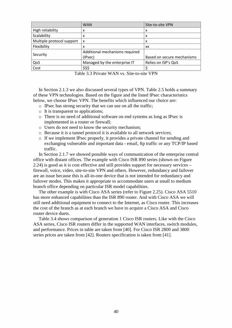
40
WAN Site-to-site VPN High reliability x x Scalability x x Multiple protocol support x x Flexibility x xx
Security Additional mechanisms required (IPsec) Based on secure mechanisms
QoS Managed by the enterprise IT Relies on ISP’s QoS Cost $$$ $
Table 3.3 Private WAN vs. Site-to-site VPN
In Section 2.1.3 we also discussed several types of VPN. Table 2.5 holds a summary
of these VPN technologies. Based on the figure and the listed IPsec characteristics below, we choose IPsec VPN. The benefits which influenced our choice are: o IPsec has strong security that we can use on all the traffic; o It is transparent to applications; o There is no need of additional software on end systems as long as IPsec is
implemented in a router or firewall; o Users do not need to know the security mechanism; o Because it is a tunnel protocol it is available to all network services; o If we implement IPsec properly, it provides a private channel for sending and
exchanging vulnerable and important data - email, ftp traffic or any TCP/IP based traffic.
In Section 2.1.7 we showed possible ways of communication of the enterprise central office with distant offices. The example with Cisco ISR 890 series (shown on Figure 2.24) is good as it is cost effective and still provides support for necessary services – firewall, voice, video, site-to-site VPN and others. However, redundancy and failover are an issue because this is all-in-one device that is not intended for redundancy and failover modes. This makes it appropriate to accommodate users at small to medium branch office depending on particular ISR model capabilities.
The other example is with Cisco ASA series (refer to Figure 2.25). Cisco ASA 5510 has more enhanced capabilities than the ISR 890 router. And with Cisco ASA we will still need additional equipment to connect to the Internet, as Cisco router. This increases the cost of the branch as at each branch we have to acquire a Cisco ASA and Cisco router device duets.
Table 3.4 shows comparison of generation 1 Cisco ISR routers. Like with the Cisco ASA series, Cisco ISR routers differ in the supported WAN interfaces, switch modules, and performance. Prices in table are taken from [40]. For Cisco ISR 2800 and 3800 series prices are taken from [42]. Routers specification is taken from [41].

41
Cisco ISR
3800 Series 2800 Series 1800 Series 890 Series Features VPN tunnels Up to 2500 Up to 1500 Up to 800 Up to 50
WAN Interface
Up to two 10/100/1000 Mbps built-in routed ports
Up to 2 10/100/1000 Mbps built-in routed ports
Up to 2 10/100/1000 Mbps built-in routed ports
1x 1000 BASE-T Gigabit Ethernet 1x 10/100 BASE-T Fast Ethernet
Switch Module
Up to 112 10/100 Mbps switch ports with optional Power over Ethernet (PoE)
Up to 64 10/100 Mbps switch ports with optional Power over Ethernet (PoE)
8-Port Managed Switch
An 8-port 10/100 Fast Ethernet managed switch with VLAN support and 4-port support for Power over Ethernet (PoE) (optional)
Firewall throughput Up to 1.1 Gbps Up to 530 Mbps Up to 125 Mbps Up to 90 Mbps
VPN throughput Up to 185 Mbps Up to 145 Mbps Up to 95 Mbps Up to 75 Mbps
IPS throughput Up to 425 Mbps Up to 145 Mbps Up to 125 Mbps Up to 90 Mbps
Remote access
IP Security (IPSec) VPNs (Triple Data Encryption Standard [3DES] or Advanced Encryption Standard [AES])
GET VPN, dynamic multipoint VPN (DMVPN), Site-to-site remote-access and dynamic VPN services: IP Security (IPsec) VPNs
Group Encrypted Transport Virtual Private Networks, Site-to-site remote-access and dynamic VPN services: IP Security (IPsec) VPNs
Site-to-site remote-access and dynamic VPN services: IP Security (IPsec) VPNs, Group Encrypted Transport VPN [GET VPN] with onboard acceleration, and Secure Sockets Layer [SSLVPN]
Content Filtering yes yes yes yes
Price $4 275 - $9 973 $898 - $7 000 $475 - $ 2 998 $360 to $832 Table 3.4 Cisco ISR Series Comparison
The 890 series routers are the lowest class ISR routers. They are suitable for small branch offices. Have sufficient firewall and IPS performance, and support Gigabit WAN interface.
ISR 1800 series have enhanced performance compared to 890 series. They offer faster performance and support for more VPN tunnels. 1800 series routers are optimum solution for small to medium sized branch offices.
ISR 2800 series have even greater performance. The firewall throughput jumps to almost four times the throughput of the 1800 series, and six times the performance of 890 series. The switch module of 2800 series routers provides 64 ports PoE. The price is also acceptable. We can acquire ISR 2800 series router at just two times the price of 1800 series, or even less. ISR 2800s are optimum solution for medium branch offices.
The last are ISR 3800 series. They are the highest class ISRs and have the best performance and features. Firewall throughput is two times the throughput of a 2800 series firewall. The IPS throughput is three times larger than the IPS throughput of 2800 series. That is why the ISR 3800 series are best to be used for medium and large branch office implementations.

42
For our branch office implementation we will use the 2800 series. We choose them because they have offer high performance at reasonable prices.
3.1.4 Designing the enterprise Internet edge topology For creating enterprise campus network part related to the remote access networks
there are different scenarios. In Section 2.1.7 of the previous chapter we showed different approaches – first with Cisco ISR; second with ASA series. Another solution is to use VPN, firewalls, and routing services on separate physical devices.
The first scenario with Cisco ISR provides cost-effective networks with all-in-one routers (shown in Figure 2.24). There are models of ISR routers for different size branch offices – small, medium, and large. With this type of equipment we gain high network performance while having only one physical device. This looks tempting solution but it also has drawbacks. Having one router to perform all needed services means that this router will be heavily used and his performance and reliability will be critical. We are also applying the configuration to one device which increases configuration complexity.
The second shown example is with Cisco ASA (PIX) series managing the site-to-site VPN connectivity (shown in Figure 2.25 ). It uses integrated firewall and VPN device design as Figure 2.11 shows. For this design topology we will also need a router to provide Internet connectivity. This design is not so hard to be managed but provides security because the firewall can statefully inspect the decrypted VPN traffic. And like the previous it faces the same drawback – one device must scale to meet the performance requirements of multiple connections, and increased configuration complexity.
The last option we will discuss is to use separate devices. We showed such topologies in Figure 2.9 and Figure 2.10. The topology in Figure 2.9 is simplified to deploy and easily scalable to add new VPN devices without changing firewall addresses. But it has one major disadvantage – the decrypted VPN traffic is not inspected by the firewall. It is better to place the VPN devices in the DMZ zone. With this topology decrypted VPN traffic is statefully inspected and we still provide moderate to high scalability. Drawback with placing VPN devices in the DMZ zone is that the configuration has increased complexity because we will need additional configuration on the firewall to support the additional interfaces, and the firewall must support policy routing to differentiate VPN versus non-VPN traffic.
After reviewing the possible network devices we choose to deploy Cisco ASA series for managing the remote connection. We use the scenario with integrated firewall and VPN devices; still we will need Cisco router for Internet connectivity. We are choosing this scenario for its average simplicity, and because decrypted VPN traffic will be statefully inspected. Although the configuration will be complicated we can use Cisco ASDM and/or SMD software to simplify it. We will apply one Cisco router and firewall appliance at each of the remote locations. Cisco router 7201 is used as border router for its high performance and supported services - uses NPE-G2 Network Processing Engine that aggregates services at 2 Mpps; supports Fast Ethernet, Gigabit Ethernet, and Packet over SONET; voice, video, and data integration.
In Section 2.1.5 we reviewed possible types of management. In our network we will use in-band management. The benefits that influenced our choice are that this management simplifies network architecture because the same network paths are used for user data and management data.

43
Figure 3.6 Campus network
Figure 3.6 shows this network topology. Network addressing is not shown yet. We will discuss it in more details later. The figure shows that the campus network is divided into several subareas – DMZ area, area for remote access VPN cluster, and area for user workstations.
We use two Cisco routers for the Internet connection to provide redundancy – it is better to have Internet connection provided by two ISPs, so when the one ISP is having connectivity issues we can still have Internet connectivity through the other.
The two Cisco ASA 5540s are used in failover mode with installed AIP-SSM module on both of them to provide IPS functions. They grant branch office users access to the public services in the DMZ zone and filter incoming and outgoing traffic.
Figure 3.7 reveals details about the DMZ zone in the Internet edge. We are using two Cisco ASA 5540s (5540-1 and 5540-2). They are configured in failover mode and on their public interfaces are connected to Cisco Catalyst switches. The switches are connected to Cisco routers (Border Router (BR) 1 and BR2) connected to the ISP providing Internet connectivity. BR1 and BR2 are configured with Hot Standby Routing Protocol (HSRP) to provide Internet connectivity redundancy. The virtual router IP address for the HSRP group is 172.30.201.5/27

44
Figure 3.7 Campus network - DMZ and Internet edge
The router and the two Cisco ASA 5540s are connected together in the subnet 172.30.201.0/27. The default gateway of each of the Cisco ASA 5540s is set to the HSRP virtual router address 172.30.201.5/27.
On the DMZ segment there are two servers with IP address of 192.168.232.100 and 192.168.232.101. From the Internet only HTTP and HTTPS traffic is allowed to these servers. They are communicating with an internal MySQL server hosted at address 10.20.4.50 (located in the data center, not shown on the figures) to retrieve information. To communicate with the internal database server the web server use TCP port 3306 (this is the port used by MySQL database server). We will allow only this communication from the web server to the internal network. This is done for security reasons and no other traffic will be allowed from the public DMZ zone to the fragile internal network. For the mail server we must allow SMTP to allow outgoing mails and IMAP to allow incoming mails. IMAP uses TCP port 143. There are secure versions of these protocols we should consider using - Secure SMTP (SSMTP) uses port 465, Secure IMAP (IMAP4-SSL) uses port 585, IMAP4 over SSL (IMAPS) uses port 993.

45
Figure 3.8 Campus network - Remote access VPN cluster
We are using two Cisco ASA 5520s combined together to support remote VPN access. They are labeled VPN-5520-1 and VPN-5520-2. We have two Cisco ASA 5520s for remote access redundancy. VPN-5520-1 will be configured as cluster master (assigned priority of 20) and VPN-5520-2 will act as cluster secondary (assigned priority of 10). VPN-5520-1 and VPN-5520-2 have load balancing communication link between each other. This communication link must be encrypted.
We will configure VPN-5520-1 (the VPN cluster master) to assign IP addresses to clients from a pool of addresses in the range 10.60.0.0/16. On the secondary VPN cluster (VPN-5520-2) we apply different pool range – 10.70.0.0/16.
On the Internet edge Cisco ASAs we add Real-Time Streaming Protocol (RTSP) inspection in order to allow users to use streaming video with applications like Apple QuickTime, Cisco IP/TV, and RealPlayer.
3.2 Organizing the remote branch offices The company may have several to dozen of branch offices. Figure 3.9 shows sample network topology deployed at the branch offices.

46
Figure 3.9 Branch Office Architecture
We choose Cisco ISR 2821 as site-to-site VPN terminating device in the branch office. Cisco ISR 2821 suits best the needs of a small to medium sized branch office. Table 3.4 provides overview of Cisco ISR features that influenced our choice. Some of them are: o Voice and video support; o 1000Mbps WAN interface; o Support for Power over Ethernet (PoE); o Good performance/price rate. The IP addressing scheme is shown in the figure. Static IP addressing is applied to all
devices that are better to have manually configured IP address - servers, printers, and routers. All other hosts on the network use the ISR router as DHCP server. The DHCP pool range is from 172.20.100.31 to 172.20.100.254. The addresses from 172.20.100.1 to 172.20.100.30 are reserved for any servers, routers, or other devices.
The branch office requires eventually a print server to handle the print queries. The enterprise servers provide all other needed services to the branch office. Branch users access the services in the enterprise centralized data center through the site-to-site VPN connection. This may add some delay and bandwidth issues but removes the need of having additional equipment in the branch LAN to address user needs. Also removes the need to bother about storing and backing up data on these servers. That is why we choose centralized data center solution.
VPN Split tunneling function is disabled, because this way the enterprise has control over branch office users Internet activity. Also, as discussed in the security section (Section 2.1.6) split tunneling can lead to compromised users’ computers in the branch and grant the attacker access to vulnerable enterprise data.
3.3 Analysis, evaluation and testing of the solution The enterprise Internet edge solution is suitable for medium to large enterprises. It offers significant performance at average high cost to meet the requirements of an enterprise for high availability, security policies, and high speed links. The branch office network solution offers security through firewall, IPS, and content filtering; high speed WAN links of 1000 Mbps; supports both streaming voice and video, but lacks
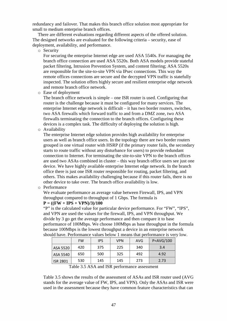
47
redundancy and failover. That makes this branch office solution most appropriate for small to medium enterprise branch offices.
There are different evaluations regarding different aspects of the offered solution. The designed networks are evaluated for the following criteria – security, ease of deployment, availability, and performance. o Security
For securing the enterprise Internet edge are used ASA 5540s. For managing the branch office connection are used ASA 5520s. Both ASA models provide stateful packet filtering, Intrusion Prevention System, and content filtering; ASA 5520s are responsible for the site-to-site VPN via IPsec connections. This way the remote offices connections are secure and the decrypted VPN traffic is statefully inspected. The solution offers highly secure and resilient enterprise edge network and remote branch office network.
o Ease of deployment The branch office network is simple – one ISR router is used. Configuring that router is the challenge because it must be configured for many services. The enterprise Internet edge network is difficult – it has two border routers, switches, two ASA firewalls which forward traffic to and from a DMZ zone, two ASA firewalls terminating the connection to the branch offices. Configuring these devices is a complex task. The difficulty of deploying the solution is high.
o Availability The enterprise Internet edge solution provides high availability for enterprise users as well as branch office users. In the topology there are two border routers grouped in one virtual router with HSRP (if the primary router fails, the secondary starts to route traffic without any disturbance for users) to provide redundant connection to Internet. For terminating the site-to-site VPN to the branch offices are used two ASAs combined in cluster – this way branch office users see just one device. We have highly available enterprise Internet edge network. In the branch office there is just one ISR router responsible for routing, packet filtering, and others. This makes availability challenging because if this router fails, there is no other device to take over. The branch office availability is low.
o Performance We evaluate performance as average value between Firewall, IPS, and VPN throughput compared to throughput of 1 Gbps. The formula is P = ((FW + IPS + VPN)/3)/100 “P” is the calculated value for particular device performance. For “FW”, “IPS”, and VPN are used the values for the firewall, IPS, and VPN throughput. We divide by 3 go get the average performance and then compare it to base performance of 100Mbps. We choose 100Mbps as base throughput in the formula because 100Mbps is the lowest throughput a device in an enterprise network should have. Performance values below 1 means that performance is very low.
FW IPS VPN AVG P=AVG/100
ASA 5520 420 375 225 340 3.4
ASA 5540 650 500 325 492 4.92
ISR 2801 530 145 145 273 2.73 Table 3.5 ASA and ISR performance assessment
Table 3.5 shows the results of the assessment of ASAs and ISR router used (AVG stands for the average value of FW, IPS, and VPN). Only the ASAs and ISR were used in the assessment because they have common feature characteristics that can

48
be compared. As the table shows, the performance of the devices is sufficient. The performance of the border routers 7201s is 2 Mpps (Millions Packets per Second) with the chosen engine NPE-G2, which means that border routers have high performance.
The overall evaluation of the solution is high, the network topologies suggested are moderate difficult to implement, yet provide high security with average to high performance.
We will test the availability of the border routers 7200 series. Both routers are configured with HSRP to provide redundant connection to the Internet. For the testing environment we use GNS3 (Graphic Network Simulator) because it gives us the ability to configure, test, and troubleshoot routers working with real IOSs.
Figure 3.10 HSRP Testing Environment
Figure 3.10 shows the testing environment we created in GNS3. We simulate only this small router segment of the enterprise Internet edge because we are only testing the redundancy provided by HSRP. “Laptop” represents the computer we have logically connected to the simulated environment on which the HSRP Virtual IP is set as default gateway. “BR1” and “BR2” are the border routers from the enterprise Internet edge topology. The configuration of the routers for HSRP is shown in Appendix B1.
HSRP works in such manner that the end user (in the figure this is “Laptop”, but in the designed topology users are both ASA 5540s) do not see the two routers as separate gateways, but see the virtual router created by HSRP and forwards traffic to the address of the virtual router. We have chosen BR1 to be the “Active” router and to router traffic destined to the virtual router, and BR2 to be the “Standby” or backup router if BR1 is down.
If we issue “ping” command from “Laptop” to verify connectivity to the gateway, we will see responses coming from device with IP 10.1.1.103. This is shown in Appendix B2.
Now in the topology we turn off the Active HSRP router BR1 to test what will be the influence on user’s gateway connectivity. Figure 3.11 shows the topology after turning off BR1. Pings to the default gateway is successful. To prove that BR1 is not responding we issued a ping to it which was unsuccessful. However, pings to BR2 IP 10.1.1.101 are successful. The result from this ping shows that the standby router BR2 has become active router for the HSRP group. Appendix B.3 shows the ping results.

49
Figure 3.11 Turning off HSRP Active router BR1
After we turn on the BR1 again we have the same topology as Figure 3.10 shows. If checking the console of BR1 and BR2 we will see the event notifications that BR1 becomes the Active HSRP router again and BR2 transitions from Active to Standby. This is achieved with “standby 1 preempt” command on BR1. Appendix B.4 shows these notification messages. Now we issue ping to the default gateway again to check the connectivity. Ping was successful. We also issue pings to BR1 and BR2 to verify they are up and running. Appendix B.5 shows the result of these pings.
As summary we can say that if we did not explicitly issue pings to BR1 and BR2 we would not understand that one of the gateways is down. The backup router transitions from Standby to Active mode and begins to forward traffic, in result the end user experiences no connectivity disturbance.
Another test we will do is to test the security of the VPN connection between the enterprise and a branch office. Figure 3.12 shows the topology we use is for the test, as well as the IP addressing scheme and used equipment.
Figure 3.12 VPN test topology
Router “Branch1” is the border router of a branch office. The “ISP” router represents the Internet. In the enterprise network we use only one router and firewall, because for the test we do not need the redundancy.

50
Now for to test the VPN connection security we need to send data from the branch office router to the enterprise border router and examine them with protocol analyzer like Wireshark. To simulate the data transition we will use ping command from router Branch1 to enterprise internal network: ping 10.10.0.1 source 10.10.1.1 repeat 300. We use the loopback interface of Branch1 router for source of the ping because this way we simulate the LAN network of the branch office. Appendix B.6 shows the result of the issued ping command. As it can be seen the ping request and reply packets have changed source and destination IP address. This is so because the traffic was encrypted before we capture it with Wireshark. If the traffic was not encrypted we would see it in clear text with the source and destination addresses we used in the ping command (Appendix B.7 shows that result).
As conclusion from the test we can say that the traffic between the enterprise and branch office networks is secure. The site-to-site VPN over IPsec connection provides strong security and data privacy.
Results
In the Theory chapter we reviewed two communication options between the enterprise and the remote branch networks – private WAN and site-to-site VPN. The possible types of private WAN were reviewed - Frame Relay, ATM, leased lines and others. The possible types of VPN implementations we also reviewed. These types include but are not limited to PPTP, IPsec, and SSL VPN. Security, management, and services for the enterprise network with remote branch offices were also discussed.
In Theory chapter we reviewed possible types of management – in-band and out-of-band management; centralized, distributed, and hierarchical management. We also reviewed possible ways of keeping management data – to a permanent (or semi-permanent) media or system. The parts of the process for keeping data were also explained - primary storage, secondary storage, and tertiary storage
For the designing we chose site-to-site VPN model as primary connection between the enterprise and the branch offices. The solution of the problem we offered is based on that model. We discussed site-to-site in more details and chose IPsec as possible implementation type. We also reviewed carefully the types of equipment to be used in the network. For any particular location we chose the most appropriate equipment.
The solution was analyzed, evaluated, and partly tested. The results show that the enterprise network solution is appropriate for medium to large enterprises. It offers high security, availability, redundancy, and high speed links. The branch office solution is appropriate for small to medium branch office implementations. It offers high security, low availability, none redundancy, and high speed links.

51
4 Discussion on results
This chapter contains discussion on the results of the designing. Here we will make final conclusion, list recommendations and make advices for future work. Each one of there will be covered in separate sections as follows conclusions in Section 4.1, recommendations in Section 4.2, and future work in Section 4.3.
4.1 Conclusion The project provides a solution to the problem. The designed enterprise computer communication network with a branched network of affiliates (described in Section 3.1.4) can support branch offices regionally-extended, international-extended or worldwide-extended. The branch offices (explained in Section 3.2) need Internet connection and equipment that supports site-to-site VPNs based on IPsec.
4.2 Recommendations The redundancy of the branch office network should be implemented. Without redundancy if the ISR router is down, the entire branch office is lost. Another ISR router could be deployed to provide redundant network.
The designed branch office network suits best the needs of a small to medium branch office. For other sizes of branch offices other equipment should be used.
4.3 Future work The used router models (7201) in the enterprise Internet edge have high performance and wide range of supported features. However, if the enterprise demands even higher performance in the future a migration to ASR 1000 series should be considered.
The enterprise communicates with the branch offices via the site-to-site VPN connection based on IPsec. But if that connection is down, the enterprise does not have any backup connectivity with the branch offices. Secondary connection between both locations could be implemented in the future.
Implementing IPv6 should also be considered in the future. IPv6 has a lot benefits over IPv4 - simplified header for routing efficiency and performance; deeper hierarchy and policies for network architecture flexibility; efficient support for routing and route aggregation; security with mandatory IP Security (IPSec) support for all IPv6 devices and others. There also migration strategies than can be deployed to facilitate the migration process.
The project offers testing of the HSRP functionality. In the future more features of the designed network could be tested to support the theory statements with testing results. These features include, but are not limited to servers’ accessibility from branch offices; the VPN cluster operation; firewall packet filtering; and VPN link bandwidth utilization.

52
References [1]. James McCabe (2007). Network Analysis, Architecture, and Design 3rd Edition [2]. Jazib Frahim, Qiang Huang (2008). Cisco Press SSL Remote Access VPNs [3]. http://en.wikipedia.org/wiki/RADIUS (visited 180410) [4]. http://www.networkcomputing.com/netdesign/soho1.html (visited 030510) [5]. http://www.pro-100.org/?oblast=0&sort=economy# (visited 060510) [6]. Diane Teare, Catherine Paquet (2005). Campus Network Design Fundamentals [7]. Richard Deal (2006). The Complete Cisco VPN Configuration Guide [8]. http://www.ibm.com/developerworks/ru/library/l-Backup_1/?S_TACT=105AGX99&S_CMP=GR01 (visited 110610) [9]. Keith Hutton, Mark Schofield (2009). Designing Cisco Network Service Architectures 2nd Edition [10]. http://www.edrivium.com/ (visited 120610) [11]. http://www.juniper.net/ (visited 120610) [12]. http://en.wikipedia.org/wiki/DMZ_%28computing%29 (visited 130610) [13]. http://campustechnology.com/Articles/2010/03/12/Machine-Hunt-User-Forensics- at-Salt-Lake-Community-College.aspx?Page=2 (visited 220610) [14]. http://www.etelemetry.com/ (visited 230610) [15] http://www.cisco.com/en/US/docs/ios/solutions_docs/ipv6/IPv6dswp.html (visited 080710) [16] http://www.groupstudy.com/bookstore/samples/Oppenheimer/index.html (visited 110710) [17] Priscilla Oppenheimer (2004). Cisco Press Top-Down Network Design Second Edition [18] Mark Lewis (2006). Cisco Press Comparing, Designing, and Deploying VPNs [19] http://www.networkworld.com/subnets/cisco/092509-ch1-intro-to-wan-architectures.html (visited 140710) [20] Wendell Odom (2010), CCNP ROUTE 642-902 Official Certification Guide [21] Bob Vachon, Rick Graziani (2008). Accessing the WAN CCNA Exploration Companion [22] http://www.ciscoguard.com/CISCO892W.asp (visited 170710) [23] http://secret-epedemiology-statistic.org.ua/1587052091/ch22lev1sec1.html (visited 180710) [24] http://iaoc.ietf.org/network_requirements.html (visited 240710) [25] http://www.archicadwiki.com/Teamwork/NetworkSpecification (visited 270710) [26] http://www.networkworld.com/newsletters/wireless/2009/052509wireless2.html (visited 040810) [27] http://www.cisco.com/en/US/prod/collateral/routers/ps9343/white_paper_c11-451583_ns592_Networking_Solutions_White_Paper.html (visited 050810) [28] http://www.cisco.com/en/US/docs/solutions/Enterprise/Branch/WAASBr11.html (visited 260810) [29] http://searchdatabackup.techtarget.com/tip/0,289483,sid187_gci1516980,00.html (visited 280810) [30] http://searchdatabackup.techtarget.com/sDefinition/0,,sid187_gci1378343,00.html (visited 280810) [31] http://www.cisco.com/application/pdf/en/us/guest/netsol/ns171/c649/ccmigration_09186a00807593b6.pdf (visited 300810) [32] http://www.cisco.com/en/US/prod/collateral/routers/ps9343/at_a_glance_c45-457081_v7.pdf (visited 010910) [34] http://www.cisco.com/en/US/prod/collateral/routers/ps341/product_data_sheet09186a008008872b.html (visited 020910) [35] http://www.cisco.com/en/US/docs/solutions/Enterprise/Security/IE_DG.html#wp42019 (visited 020910) [36] http://www.cisco.com/en/US/products/ps5882/index.html (visited 260810) [37] http://www.cisco.com/en/US/products/ps5855/index.html (visited 270810) [38] http://www.cisco.com/en/US/prod/routers/networking_solutions_products_genericcontent0900aecd806cab99.html (visited 270810)

53
[39] http://www.cisco.com/en/US/prod/collateral/vpndevc/ps6032/ps6094/ps6120/product_data_sheet0900aecd802930c5.html (visited 280810) [40] http://shopper.cnet.com (visited 300810) [41] http://www.cisco.com/en/US/products/hw/routers/index.html (visited 300810) [42] http://www.router-switch.com (visited 010910) [43] http://www.nextag.com (visited 010910) [44] http://www.cisco.com/en/US/products/hw/switches/#~all-prod (visited 010910)

54
Appendix A
Network documents and decisions
Appendix A.1 New York branch office configuration ! The public outside interface interface GigabitEthernet0/0 nameif outside security-level 0 ip address 209.165.200.231 255.255.255.224 ! ! The private inside interface interface GigabitEthernet0/1 nameif inside security-level 100 ip address 10.165.200.231 255.255.255.0 ! ! hostname NewYork ! !The following access control list entries restrict internal users to only be able to !send HTTP, HTTPS, and DNS traffic to the Internet access-list insideACL extended permit tcp 10.165.200.0 255.255.255.0 any eq www access-list insideACL extended permit tcp 10.165.200.0 255.255.255.0 any eq https access-list insideACL extended permit udp 10.165.200.0 255.255.255.0 any eq domain ! !The following access control list entries restrict internal users to only be able to !send TCP port 8912 and 8913 traffic to the 10.20.1.60 server in Washington, which hosts !the previously mentioned third-party application. access-list insideACL extended permit tcp 10.165.200.0 255.255.255.0 host 10.20.1.60 eq 8912 access-list insideACL extended permit tcp 10.165.200.0 255.255.255.0 host 10.20.1.60 eq 8913 ! !The following access control list entries restrict internal users to only be able to !send SMTP, POP3, and IMAP4 traffic to the 10.20.4.50 mail server in Washington. access-list insideACL extended permit tcp 10.165.200.0 255.255.255.0 host 10.20.4.50 eq smtp access-list insideACL extended permit tcp 10.165.200.0 255.255.255.0 host 10.20.4.50 eq pop3 access-list insideACL extended permit tcp 10.165.200.0 255.255.255.0 host 10.20.4.50 eq imap4 ! !The following access control list entry allows the 10.10.220.0/24 management segment in !Washington to be able to launch a remote control session to the internal user workstations !in NY. access-list outsideACL extended permit tcp 10.10.220.0 255.255.255.0 10.165.200.0 255.255.255.0 eq 7788

55
! !The following access control list entries are used to define what traffic should be !encrypted over the IPSec site-to-site tunnel to Washington. access-list encryptACL extended permit ip 10.165.200.0 255.255.255.0 10.20.4.0 255.255.255.0 access-list encryptACL extended permit ip 10.165.200.0 255.255.255.0 10.20.1.0 255.255.255.0 access-list encryptACL extended permit ip 10.165.200.0 255.255.255.0 10.10.220.0 255.255.255.0 ! !The following access control list entries allows the ASA to bypass NAT for the IPSec !tunnel traffic. access-list nonat extended permit ip 10.165.200.0 255.255.255.0 10.20.4.0 255.255.255.0 access-list nonat extended permit ip 10.165.200.0 255.255.255.0 10.20.1.0 255.255.255.0 access-list nonat extended permit ip 10.165.200.0 255.255.255.0 10.10.220.0 255.255.255.0 ! !The following NAT configuration allows all the internal devices within the !10.165.200.0/24 network to be port address translated to the outside interface address !except for the VPN traffic. global (outside) 1 interface nat (inside) 0 access-list nonat nat (inside) 1 10.165.200.0 255.255.255.0 ! !Access-lists are applied to the corresponding access-groups access-group insideACL in interface inside access-group outsideACL in interface outside ! ! Default gateway pointing to the external router's IP address route outside 0.0.0.0 0.0.0.0 209.165.200.232 1 ! !The following is the IPSec site-to-site tunnel configuration to the Washington ASA !209.165.201.1. crypto ipsec transform-set myset esp-aes-256 esp-sha-hmac crypto map IPSec_map 10 set peer 209.165.201.1 crypto map IPSec_map 10 set transform-set myset crypto map IPSec_map 10 match address encryptACL crypto map IPSec_map interface outside isakmp enable outside isakmp policy 10 authentication pre-share isakmp policy 10 encryption aes-256 isakmp policy 10 hash sha isakmp policy 10 group 2 isakmp policy 10 lifetime 86400 tunnel-group 209.165.201.1 type ipsec-l2l tunnel-group 209.165.201.1 ipsec-attributes pre-shared-key 1qaz@WSX

56
The sysopt connection permit-ipsec command is not used in Figure 2.25 configuration. “This is purposefully done to ensure that the decrypted VPN traffic passes through the interface ACL applied to the outside interface.” [23]
Appendix A.2 Configuration commands enhancing network equipment security
Disabling unnecessary services o Cisco access router no service pad ! no ip source-route no ip bootp server no ip domain lookup ! interface XXX no ip redirects no ip unreachables no ip proxy-arp ! no ip http server o Cisco Catalyst switch no service pad ! no ip domain-lookup ! no ip http server o Cisco ASA Appliance – These features are not enabled on an ASA, so no action is
required.
Enabling Logging o Cisco access router service timestamps debug datetime msec service timestamps log datetime localtime ! logging count logging buffered 8192 debugging logging rate-limit 5 o Cisco Catalyst switch service timestamps debug uptime service timestamps log uptime ! logging count logging buffered 8192 debugging logging rate-limit 5 o Cisco ASA Appliance logging enable logging buffered emergencies logging asdm informational

57
Using SSH instead of Telnet for Remote Administration o Cisco access router hostname access-router ip domain name ese.cisco.com ! cry key generate rsa general-keys modulus 1024 ! ip ssh version 2 ip ssh time-out 60 ip ssh authentication-retries 2 ip ssh source-interface GigabitEthernet0/1 ! line vty0 15 Transport input ssh o Cisco Catalyst switch hostname catalyst-switch ip domain name ese.cisco.com ! cry key generate rsa general-keys modulus 1024 ! ip ssh version 2 ip ssh time-out 60 ip ssh authentication-retries 2 ip ssh source-interface Vlan193! ! line vty 0 15 Transport input ssh o Cisco ASA Appliance hostname asa-appliance domain-name ese.cisco.com ! cry key generate rsa modulus 1024 ! ssh timeout 5
Enabling HTTPS server built in Cisco devices o Cisco access router ip http secure-server ! o Cisco Catalyst switch ip http secure-server ! o Cisco ASA Appliance http server enable http 172.16.1.0 255.255.255.0 management http 34.100.0.0 255.255.0.0 management

58
Restricting accepted connections on VTY and Console lines o Cisco access router line con 0 transport output all ! line aux 0 transport output all ! line vty 0 4 password 7 1511021F0725 exec prompt timestamp transport input ssh transport output all o Cisco Catalyst switch line con 0 transport output all ! line vty 0 4 exec-timeout 60 0 password 7 02050D480809 exec prompt timestamp transport input ssh ! line vty 5 15 password 7 02050D480809 exec prompt timestamp transport inputssh o Cisco ASA Appliance ssh 10.10.10.0 255.0.0.0 dmz 1 ssh 20.0.0.0 255.255.0.0 inside ssh scopy enable (enter a line for each subnet that is allowed SSH access) ! ssh timeout 5 console timeout 0
Managing passwords with AAA on all devices o Cisco access router service password-encryption enable secret 5 $1$1ZoH$eUqctzD0NrObry5sgk/jz0 ! aaa new-model ! aaa authentication login ssh_users group tacacs+ aaa accounting send stop-record authentication failure aaa accounting exec ssh_users start-stop group tacacs+ aaa accounting commands 7 ssh_users start-stop group tacacs ! aaa session-id common !

59
login block-for 30 attempts 3 within 200 login delay 2 ! username cisco password 7 121A0C041104 ! ip tacacs source-interface Loopback0 ! tacacs-server host 10.59.138.11 single-connection tacacs-server directed-request tacacs-server key 7 13061E010803557878 ! o Cisco Catalyst switch version 12.2 service password-encryption enable password 7 110A1016141D aaa authentication login ssh_users group tacacs+ aaa accounting send stop-record authentication failure aaa accounting exec ssh_users start-stop group tacacs+ aaa accounting commands 7 ssh_users start-stop group tacacs ! aaa session-id common ! login block-for 30 attempts 3 within 200 login delay 2 ! username cisco password 7 121A0C041104 ! ip tacacs source-interface Loopback0 ! tacacs-server host 10.59.138.11 single-connection tacacs-server directed-request ! tacacs-server key 7 13061E010803557878 o Cisco ASA Appliance passwd 2KFQnbNIdI.2KYOU encrypted ! aaa-server tacacs-group protocol tacacs+ aaa-server tacacs-group host 10.59.138.11 key Cisco aaa-server TACACS+ protocol tacacs+ ! aaa authentication enable console tacacs-group LOCAL aaa authentication ssh console tacacs-group LOCAL aaa authentication telnet consol tacacs-group LOCAL ! aaa authentication serial console tacacs-group LOCAL ! aaa authorization command tacacs-group LOCAL ! aaa accounting telnet console tacacs-group aaa accounting ssh console tacacs-group aaa accounting command tacacs-group

60
Appendix B
Test results
Appendix B.1 o Configuration of BR1 ! interface FastEthernet0/0 ip address 10.1.1.100 255.255.255.0 no ip redirects duplex auto speed auto standby 1 ip 10.1.1.103 standby 1 priority 150 standby 1 preempt ! interface FastEthernet0/1 ip address 20.20.20.1 255.255.255.252 duplex auto speed auto ! o Configuration of BR2 ! interface FastEthernet0/0 ip address 10.1.1.101 255.255.255.0 no ip redirects duplex auto speed auto standby 1 ip 10.1.1.103 ! interface FastEthernet0/1 ip address 20.20.20.2 255.255.255.252 duplex auto speed auto ! ip forward-protocol nd !
Appendix B.2

61
Appendix B.3
Appendix B.4

62
Appendix B.5
Appendix B.6
Appendix B.7

SE-351 95 Växjö / SE-391 82 Kalmar Tel +46-772-28 80 00 [email protected] Lnu.se