computer vision based surveillance concept for airport ...€¦ · computer vision based...
TRANSCRIPT

COMPUTER VISION BASED SURVEILLANCE CONCEPT FOR AIRPORT
RAMP OPERATIONS
Sai Vaddi & Hui-Ling Lu, Optimal Synthesis Inc., Los Altos, CA
Miwa Hayashi, NASA Ames Research Center, Moffett Field, CA
Abstract
Current research develops a vision-based
surveillance system concept suitable for airport ramp
area operations. The surveillance approach consists
of computer vision algorithms operating on video
streams from surveillance cameras for detecting
aircraft in images and localizing them. Rough order
of magnitude estimates of the number of cameras
required to cover the ramp area at a sample airport
(Dallas/Fort Worth International Airport) were
obtained. Two sets of algorithms with complimentary
features were developed to detect an aircraft in a
given image. The first set of algorithms was based on
background subtraction, a popular computer-vision
approach, for change detection in video streams. The
second set was a supervised-learning approach based
on a model learned from a database of images. The
Histogram of Oriented Gradient (HOG) feature was
used for classification with Support Vector Machines
(SVMs). Then, an algorithm for matching aircraft in
two different images was developed based on an
approximate aircraft localization algorithm. Finally,
stereo-vision algorithms were used for 3D-
localization of the aircraft. A 1:400 scale model of a
realistic airport consisting of a terminal building, jet
bridges, ground marking, aircraft, and ground
vehicles was used for testing the various algorithms.
Aircraft detection was demonstrated using static and
moving aircraft images, single and multiple aircraft
images, and occluded aircraft images. Preliminary
testing using the in-house setup demonstrated 3D
localization accuracy of up to 30 ft.
Introduction
Ramp areas in airports are densely occupied
by aircraft, ground vehicles, and ground crew. At
most airports ramp areas are not covered by
surveillance systems such as RADAR and Airport
Surface Detection Equipment - Model X (ASDE-X).
Even when surveillance systems such as Automatic
Dependent Surveillance -Broadcast (ADS-B) are
available they require the aircraft avionics to be
powered on, whereas some aircraft in the ramp area
may have the avionics system turned off. Another
drawback of surveillance technologies in ramp area is
that technologies, such as RADAR and Global
Positioning System (GPS) based ADS-B, suffer from
multi-path errors in the ramp area thus compromising
the accuracy [1].
The proposed vision-based surveillance
system overcomes the above obstacles as it does not
require any aircraft equipage and participation. It is a
ground-based passive surveillance system. Therefore,
it does not suffer from multi-path errors.
Vision-based surveillance systems have
found significant applications in monitoring the
security of public places as well as private
businesses. However, in these applications they
typically aid the humans by combining the feeds
from multiple cameras into a single view for the
monitoring personnel. In other applications, vision
based approaches have been used for road
surveillance [2]. Refs. [3] and [4] specifically deal
with vision-based surveillance approaches for airport
surface traffic. However, the functional, algorithmic,
and performance details of these concepts
specifically applied to the densely populated ramp
area, are not available at the moment for comparison.
Surveillance in ramp area has multiple
benefits:
Surveillance information can enable safety
monitoring systems (such as Refs. [5], [6]) for
ramp area operations. The Flight Safety

Foundation estimates that 27,000 accidents
occur on airport ramps worldwide each year,
and 243,000 people are injured, or roughly
one injury for every 111 departures [7].
Industry experts put the airlines' cost due to
ramp area accidents at $4 billion to $5 billion
internationally each year [8].
Real-time surveillance updates could aid in
better planning gate release and ramp spot
release/sequence operations by planners such
as the Spot and Runway Departure Advisor
(SARDA) [9] by providing real-time updates
on the pushback and taxi status of the aircraft.
SARDA was developed by the Safe and
Efficient Surface Operations (SESO) group at
NASA Ames Research Center.
Figure 1 shows the functional architecture of
the proposed concept. The primary inputs come in the
form of video streams from surveillance cameras.
Auxiliary inputs are the schedule data, and other
surveillance information, if any. The first set of
algorithmic modules processing the video data
consists of the ‘Aircraft and Ground Vehicle
Detection’ modules (purple colored blocks in Figure
1). The purpose of these modules is to detect the
presence of aircraft or ground-vehicles in a given
image frame. The second module is the aircraft
localization module whose task is to estimate the 3D
location of the aircraft in an inertial frame of
reference. This is done in two sub-modules: (i)
Aircraft Matching, and (ii) 3D-Localization (orange
colored blocks in Figure 1). The Aircraft Matching
module matches the aircraft identified in image
frames obtained from different cameras. The 3D-
Localization module uses stereo-vision algorithms to
estimate the 3D location using two images of the
same aircraft obtained from two different cameras.
Figure 1. Functional Architecture of the Proposed Concept
The last module is the Data Fusion Module
(gray colored blocks in Figure 1) which deals with
tracking aircraft over multiple cameras. This involves
data-association and state estimation algorithms. The
blue colored blocks indicate data sources that could
aid the overall system. The overall output from the

surveillance system consists of aircraft ID; position
coordinates of the aircraft ; gate where the aircraft
is parked; speed and heading if the aircraft is
moving. Advanced vision-based algorithms are also
capable of generating aircraft orientation information.
Apart from the surveillance mode, the
proposed system can be used in a post-processing
mode to conduct surveillance video data analysis. In
this mode the proposed system can identify the paths
taken by aircraft in the ramp area; model the statistics
of time taken by aircraft to move from gate to ramp
spot; identify special events of interest such as
simultaneous push back from adjacent gates.
Camera Requirements
The following are design parameters of a
camera-based surveillance system:
Wave length of operation (e.g., Visible,
Infrared, which is suitable for night-time and
low-visibility operations)
Number of cameras
Location & orientation of cameras
Focal length ( ) of the cameras
Imaging sensor size ( ) of the cameras
Resolution of the imaging sensor
Type of lens (e.g., Wide Angle, Fish eye,
Panoramic)
Degrees of freedom (i.e., Pan, Tilt, and/or
Zoom).
A pin-hole camera model (Figure 2) is used
to compute the approximate number of cameras
required to provide complete coverage for a sample
airport, Dallas/Ft. Worth International Airport
(DFW).
Figure 2. Pinhole Camera Model
The following is the basic equation that
describes the perspective transformation resulting
from a camera. An object of length, , at a distance,
, from the camera is shrunk to a length, , which is
dependent on the focal length of the camera, .
(1)
The field-of-view of a camera is an important
parameter that determines the geographical area
captured by the camera. It depends on the focal
length, , and the size of the imaging sensor, , and is
typically characterized by the angle, .
The total number of cameras required to
cover the complete ramp area depends on the area of
the ramp represented by , and the
maximum area captured by a single camera
. It can be approximated by the following
equations:
(2)
= (3)
where is the length to width ratio of the imaging
sensor; and is the maximum object length that
could be captured by a camera at a distance .
(4)
It should be noted that the above equation is
an approximation. It assumes no occlusions and
assumes the feasibility of placing the cameras at
specified distance, . The actual number of cameras
could be higher. However, the above equation
provides valuable insight into the camera
requirements as explained by the following relations:
(5)
(6)
Typical sensor sizes could range from a
minimum of 4mm in width to a maximum of up to
36mm. The focal length of cameras can vary from as
low as 2.5mm to as high as 1m. Corresponding fields
of view could vary between 50 degrees to
150 degrees. Figure 3-Figure 4 illustrate the number
of camera requirements for cameras with different
FOVs.
f D
L
l
s
Imaging Sensor Size
Focal Length

Figure 3. Required Numbers of Cameras with
50deg FOV Cameras
Figure 4. Required Numbers of Cameras with
100deg FOV Cameras
The three plots within each figure indicate
the number of cameras required for single-camera
coverage, double-camera coverage, and triple-camera
coverage. Single-camera coverage refers to a scenario
where each point is only viewed by a single camera.
For purposes such as 3D-localization it is desired that
the same aircraft be imaged by at least two cameras
(double-camera coverage). Multiple cameras looking
at the same aircraft from different angles also
increases the robustness of aircraft detection.
The hyperbolic nature of the plots indicates
the inverse proportionality with the square of the
distance from the camera. It can also been seen by
comparing Figure 3 and Figure 4 that doubling the
FOV more than halves the number of cameras.
From these figures it can be concluded that
for a 50 degree field-of-view camera placed 1000 ft
from the area of interest could require as many as 50
cameras for double-camera coverage for a ramp area
whose size is same as that of the DFW ramp area. It
should be noted that DFW has relatively large ramp
areas. Smaller airports could require less than half
this number. It should also be noted that the above
analysis does not take into account camera placement
restrictions and occlusions. It is intended to be an
approximate analysis to get a rough order of
magnitude estimate of the number of cameras
required for the proposed surveillance system.
Aircraft Detection Module
The role of this module is to sample each
video frame and evaluate if an aircraft is present in
the frame. Two different algorithms (i) Background-
Subtraction Algorithm and (ii) Supervised-Learning
Algorithm were developed for this purpose. The
following sub-sections present the approach and the
results obtained using the two algorithmic
approaches.
Background-Subtraction Algorithm
The Background-Subtraction approach relies
on the following premises: (i) The camera view is
fixed. (ii) The scope of view consists of two
components: (a) static terminal component, and (b)
dynamic moving components. (iii) The dynamic
moving components consist of aircraft, ground
vehicles, and ground crew. (iv) Approximate sizes of
the aircraft, ground vehicles, and ground crew are
known.
Figure 5 shows a block diagram of this
algorithmic approach. The inputs to this algorithm
are an image of the background, and a sample image
that may or may not contain an aircraft. The first step
involves differencing and thresholding the difference
to identify pixels whose values deviate from the
background (see Figure 6). The second step involves
clustering these pixels using K-Means algorithm (see
Figure 7). The third step involves identifying the
3sigma ellipsoids associated with each cluster (see
500 600 700 800 900 10000
50
100
150
200
250
300
Camera Distance to Ramp Area (ft)
No
of
Cam
era
s
Field of View = 50deg
Single Camera Coverage
Double Camera Coverage
Triple Camera Coverage
500 600 700 800 900 10000
5
10
15
20
25
30
35
40
45
Camera Distance to Ramp Area (ft)
No
of
Cam
era
s
Field of View = 100deg
Single Camera Coverage
Double Camera Coverage
Triple Camera Coverage

Figure 8). The last step involves discarding small and
low-density clusters, as well as combing nearby
clusters (see Figure 9).
Figure 5. Functional Flow Diagram of the Background-Subtraction-Based Approach
Figure 6. Difference Image
Figure 7. K-Means Clustered Image
Figure 8. Image with Cluster 3Sigma Ellipsoids
Figure 9. Final Image with Bounding Box
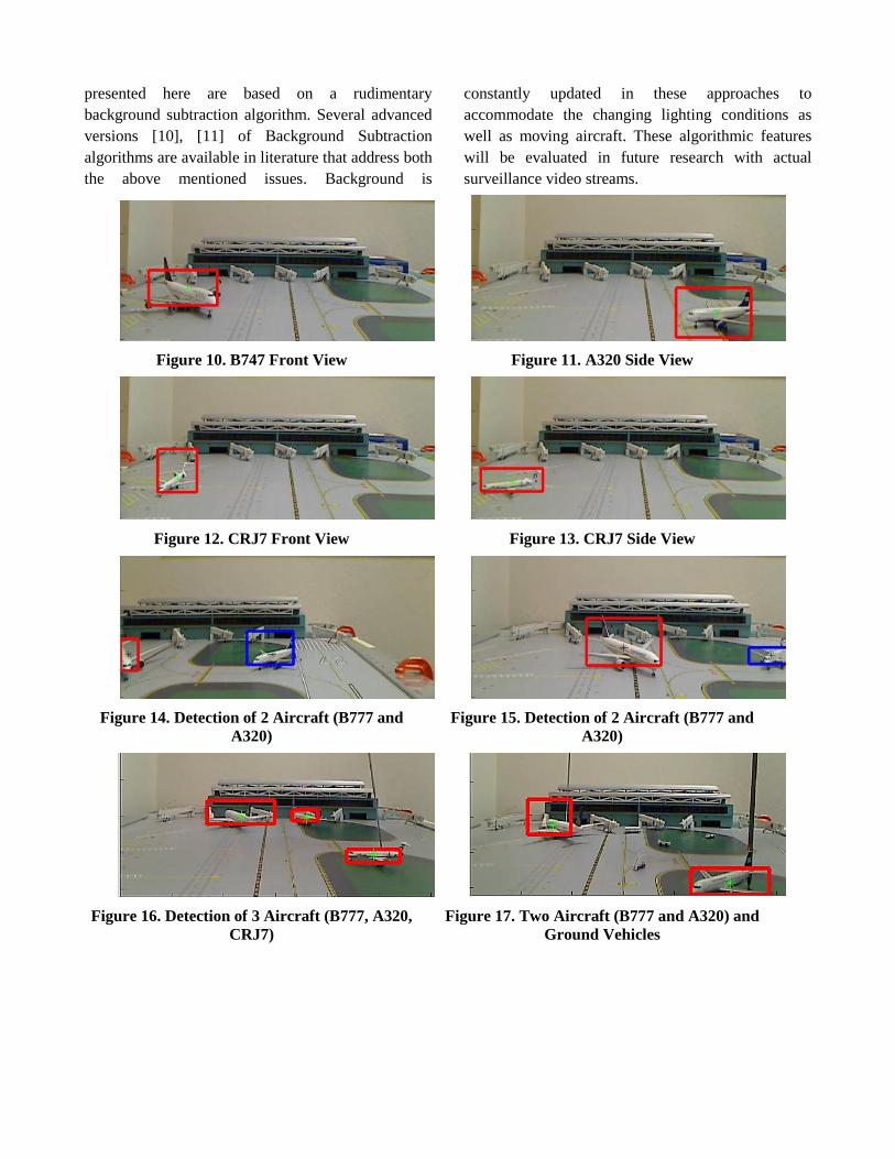
Results obtained applying the Background-
Subtraction approach to pictures of a 1:400 scale
model of an airport are shown in Figure 10-Figure
19. The results include different aircraft types,
different orientations, and different locations. Figure
14-Figure 17 show multiple aircraft detection as well.
Figure 17 and Figure 18 demonstrate detection
amidst ground vehicles. It should be noted that the
ground vehicles were not part of the background.
One of the challenges of the Background
Subtraction approach is the ability to deal with
changing lighting conditions of the background.
Another challenge emanates from the fact that it may
not be possible to get a background image without
any aircraft or ground vehicles in the image. Results
presented here are based on a rudimentary
background subtraction algorithm. Several advanced
versions [10], [11] of Background Subtraction
algorithms are available in literature that address both
the above mentioned issues. Background is
constantly updated in these approaches to
accommodate the changing lighting conditions as
well as moving aircraft. These algorithmic features
will be evaluated in future research with actual
surveillance video streams.
Figure 10. B747 Front View
Figure 11. A320 Side View
Figure 12. CRJ7 Front View
Figure 13. CRJ7 Side View
Figure 14. Detection of 2 Aircraft (B777 and
A320)
Figure 15. Detection of 2 Aircraft (B777 and
A320)
Figure 16. Detection of 3 Aircraft (B777, A320,
CRJ7)
Figure 17. Two Aircraft (B777 and A320) and
Ground Vehicles

Figure 18. B777 Pushback with Ground Vehicles
Figure 19. B777 Arrival at Gate
Supervised-Learning Algorithm
Another set of aircraft detection algorithms
was built based on Discriminatively Trained
Deformable Part Models (Refs. [12], [13] ). This
aircraft detection system does not require any prior
assumption regarding the aircraft to be detected.
Instead, it relies on pre-learnt aircraft models to infer
the existence of the aircraft in the input image. The
output is a binary variable indicating the presence of
an aircraft; a bounding box representing the image
plane location of the aircraft; and a coarse orientation
angle.
During the learning stage, we construct the
aircraft models from a database which contains
aircraft of different types taken at various view-
points. The Histogram-of-Orientation-Gradient
(HOG) [14] feature is used for training purposes. The
HOG feature is robust to scale and illumination
variations. Figure 20 illustrates the calculation of the
HOG feature for a single cell with the dimension of 8
by 8. HOG, as the name suggests, deals with a
histogram of gradients. The gradients can be
computed along the axis, axis or other directions
as well. Once the gradients are computed over several
pixels the information is encapsulated into a
histogram representation. The histogram
representation obviates the necessity to exactly
compute the edges. It instead relies on the overall
distribution of edge or gradient orientations at pixel
level. The overall distribution (or histogram) tends be
more robust to scale and illumination variations.
Figure 20. Computation of the HOG Feature
During the detection stage, the aircraft
detection system scans through the image and queries
the existence of the aircraft via the pre-built classifier
which utilizes the aircraft model information. Support
Vector Machine (SVM) framework is used for
inference in Refs. [12], [13].
A few snapshots of the results obtained from
the supervised-learning algorithm are shown in
Figure 21-Figure 24. These results are for four
different aircraft types in different views.
The success of learning-based approaches is
dependent on the quality and quantity of the training
data used. However, SVM aided learning approaches
remain one of the most successful computer-vision
approach for object detection. Whereas, the generic
computer-vision problem seeks to identify a wide-
variety of objects from a wide-variety of backgrounds
the current problem is more focused. In that, it is
based on a fixed camera location; restricted to
detection of aircraft; and can also be adapted to
individual ramp area for improved detection
efficiency. These issues will be addressed in future
research.

Figure 21. B747 Front View
Figure 22. B747 Side View
Figure 23. B777 Side View
Figure 24. B737 AND CRJ700
Aircraft Detection Algorithm Comparison
The previous two sub-sections described two
different algorithms for aircraft detection. The
success of proposed vision-based surveillance system
is crucially dependent on the success of the aircraft
detection module. It should be noted that these two
algorithms have different strengths and weaknesses.
The background-subtraction approach is simple and
takes advantage of the continuous video information
but requires the accurate maintenance of background
information. The supervised-learning approach
benefits from the large number of trained aircraft
examples. Specifically, the HOG feature is robust to
scale and illumination variations. However, it
requires a large amount of training data to generate
accurate results.
Aircraft Matching Module
The first step in 3D-localization using stereo-
vision is to match aircraft obtained from different
cameras. This problem is referred to as ‘Image
Correspondence’ in computer vision parlance. In the
context of the current research the problem is defined
as follows: “Given two images, each containing an
aircraft bounding box, are these two aircraft the
same?”.
An algorithm that is based on approximate
aircraft localization is used in this research for
matching aircraft in two different images. An
approximate location of the aircraft is computed
based on a single aircraft image. Figure 25 shows the
Cartesian coordinate system used in this research. It
should be noted that the axis matches the optical
axis of the camera and captures the depth coordinate
of the aircraft from the camera; the plane
matches the image plane; and the coordinate
represents the height coordinates of the aircraft with
respect to the ground.
Figure 25. Cartesian Coordinate System Used for
Aircraft Localization
Picture 228: maxDetVal 0.075569 Component:6 Picture 227: maxDetVal -0.51039 Component:3
Picture 101: DetVal -0.01061 Component:5 DetVal -0.14957 Component:3
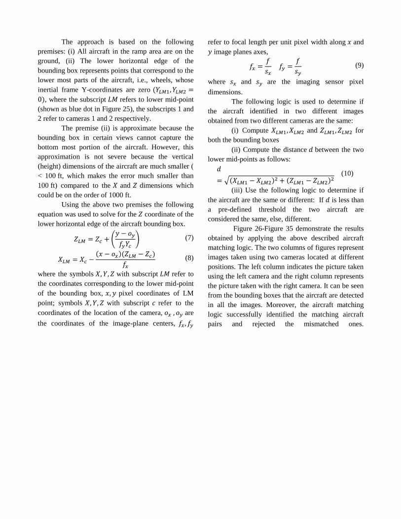
The approach is based on the following
premises: (i) All aircraft in the ramp area are on the
ground, (ii) The lower horizontal edge of the
bounding box represents points that correspond to the
lower most parts of the aircraft, i.e., wheels, whose
inertial frame Y-coordinates are zero
, where the subscript refers to lower mid-point
(shown as blue dot in Figure 25), the subscripts 1 and
2 refer to cameras 1 and 2 respectively.
The premise (ii) is approximate because the
bounding box in certain views cannot capture the
bottom most portion of the aircraft. However, this
approximation is not severe because the vertical
(height) dimensions of the aircraft are much smaller (
< 100 ft, which makes the error much smaller than
100 ft) compared to the and dimensions which
could be on the order of 1000 ft.
Using the above two premises the following
equation was used to solve for the coordinate of the
lower horizontal edge of the aircraft bounding box.
(7)
(8)
where the symbols with subscript refer to
the coordinates corresponding to the lower mid-point
of the bounding box, pixel coordinates of LM
point; symbols with subscript refer to the
coordinates of the location of the camera, are
the coordinates of the image-plane centers,
refer to focal length per unit pixel width along and
image planes axes,
(9)
where and are the imaging sensor pixel
dimensions.
The following logic is used to determine if
the aircraft identified in two different images
obtained from two different cameras are the same:
(i) Compute and for
both the bounding boxes
(ii) Compute the distance between the two
lower mid-points as follows:
(10)
(iii) Use the following logic to determine if
the aircraft are the same or different: If is less than
a pre-defined threshold the two aircraft are
considered the same, else, different.
Figure 26-Figure 35 demonstrate the results
obtained by applying the above described aircraft
matching logic. The two columns of figures represent
images taken using two cameras located at different
positions. The left column indicates the picture taken
using the left camera and the right column represents
the picture taken with the right camera. It can be seen
from the bounding boxes that the aircraft are detected
in all the images. Moreover, the aircraft matching
logic successfully identified the matching aircraft
pairs and rejected the mismatched ones.

Figure 26. Left Camera Image
Figure 27. Matched Right Camera Image
Figure 28. Left Camera Image
Figure 29. Unmatched Right Camera Image
Figure 30. Left Camera Image
Figure 31. Unmatched Right Camera Image
Figure 32. Left Camera Image
Figure 33. Matched Right Camera Image
Figure 34. Left Camera Image
Figure 35. Matched Right Camera Image

Aircraft Localization Module
The objective of this module is to compute
the 3D position coordinates corresponding
to the centroid of an aircraft in an inertial reference
frame.
Inputs are:
The pixel coordinates and of the
centroids of two matched aircraft obtained from
two different cameras. The centroids of the
bounding boxes are treated as the centroids of the
aircraft.
The locations of the two cameras are
and .
The intrinsic parameters of the cameras
and .
Outputs are 3D position coordinates
of the aircraft centroid.
The following equations are valid for the
projection of a point on to the image planes.
The subscripts and refer to Camera 1 and Camera
2 respectively.
(11)
(12)
(13)
(14)
The above equations can be rearranged into
the following matrix form:
(15)
Given the intrinsic parameters and locations
of the cameras, and pixel coordinates of the same
point in both the images, it is possible to solve the
above system of linear equations for the 3D location
of the point . A single camera only results in
two equations (say equations 11 & 12, or 13 & 14) in
three unknowns and . Therefore, a unique
solution cannot be obtained. Having multiple cameras
creates more constraints (or equations) on the three
unknowns and resulting in a more accurate
solution.
Figure 36, Figure 37, and Figure 38 show the
aircraft localization accuracy along the , , and
axes respectively. The 3D-position localization
accuracy is shown in Figure 39. These errors are
obtained from 16 different aircraft localization tests.
The x-axis refers to the test number. The errors
shown here are scaled up 400 times to map the results
of 1/400 scale model into a real-world setting. It
should be noted that the maximum errors in these
figures are less than 30 ft, which is small compared to
the size of the ramp area and the size of the aircraft.
The errors in these figures are computed as Actual
Values - Estimated Values. The biases in the figures
reflect in part the inability to measure the Actual
Position of the aircraft in the camera coordinate
system. This is in turn due to the fact that the origin
of the coordinate system which is attached to the
imaging sensor could only be approximately located
in the cameras used under the current research. The
biases however can be estimated and rejected through
a calibration process.
Figure 36. Localization Accuracy along X-Axis
0 2 4 6 8 10 12 14 16-12
-10
-8
-6
-4
-2
0
Test #
Err
or x
(ft
)

Figure 37. Localization Accuracy along Y-Axis
Figure 38. Localization Accuracy along Z-Axis
Figure 39. 3D-Position Localization Accuracy
Summary
Overall, the paper formulated a vision-based
surveillance concept for airport ramp area operations.
Surveillance in the ramp area can improve both
safety and efficiency of the ramp area operations. The
paper identified the key algorithmic modules that
would be necessary for implementing the concept.
Two algorithms with complimentary features were
proposed for aircraft detection. An innovative
approach for matching aircraft from different cameras
has been identified. Sample versions of the
algorithms were implemented and demonstrated on a
realistic 1:400 scale model of the ramp area and
aircraft. Preliminary results indicate the localization
accuracy to be around 30ft which is much less than
the size of the aircraft.
Challenges
The performance of the vision-based system
under night-time and low-visibility conditions poses
a primary challenge. The current paper does not
address this issue. An infrared camera is required for
handling these low-lighting scenarios. Some other
challenges include high-frequency variations in
illumination, camera jitter, shadows, occlusions, and
the effects of ground-traffic. Another challenge is the
fusion of the information resulting from the computer
vision algorithms with other surveillance data.
Future Work
A significant portion of our future work
involves extensive evaluation of the performance of
the aircraft detection and aircraft localization
algorithms using actual ramp area surveillance video
data. Individual algorithmic modules are expected to
be refined as part of this testing process. Work is also
required for evaluating the algorithms using data
from infrared cameras which are suitable for night-
time and low-visibility conditions. Future work also
involves formulating the data-fusion framework.
References
[1] Guilloton, A., Arenthens, J-P., Escher, A-C.,
Macabiau, C., and Koenig, D., “Multipath Study on
0 2 4 6 8 10 12 14 160
1
2
3
4
5
6
7
Test #
Err
or y
(ft
)
0 2 4 6 8 10 12 14 160
5
10
15
20
25
30
Test #
Err
or z
(ft
)
0 2 4 6 8 10 12 14 160
5
10
15
20
25
30
Test #
To
tal E
rro
r (f
t)

the Airport Surface,” IEEE 2012 Position Location
and Navigation Symposium (PLANS), 23-26 April
2012, Myrtle Beach, SC, DOI:
10.1109/PLANS.2012.6236902.
[2] http://www.videosurveillance.com/traffic.asp,
viewed on 8/7/2013
[3] http://www.searidgetech.com/ansp/lcgs, viewed
on 8/7/2013
[4] http://www.gvdigital.com/gvdweb/html/, viewed
on 8/7/2013
[5] Vaddi, S., Sweriduk, G., Kwan, J., Lin, V.,
Nguyen, J., and Cheng, V. H. L., “Concept and
Requirements for Airport Surface Conflict Detection
and Resolution,” Proceedings of the Aviation
Technology Integration and Operations Conference,
Virginia Beach, Virginia, September 2011
[6] Vaddi S. S., Kwan, J., Fong, A., and Cheng, V. H.
L., “Deterministic and Probabilistic Conflict
Detection Algorithms for NextGen Airport Surface
Operations,” Proceedings of the Guidance,
Navigation, and Control Conference, Minneapolis,
Minnesota, August 2012
[7] http://flightsafety.org/asw/aug08/asw_aug08.pdf,
page 44, as viewed on Sep 5, 2011.
[8]
http://www.iasa.com.au/folders/Safety_Issues/RiskM
anagement/rampwoes.html, as viewed on Sep 5,
2011.
[9] Jung, Y. C., Hoang, T., Montoya, J., Gupta,
G., Malik, W., and Toibas, L., “A Concept and
Implementation of Optimized Operations of Airport
Surface Traffic,” Proceedings of the 2010 AIAA
Aviation, Technology, Integration and Operations
Conference, September, 2010.
[10] Evangelio, R. H., and Sikora, T, “Static
Object Detection Based on a Dual Background
Model and a Finite-State Machine,” Journal of Image
and Video Processing, doi:10.1155/2011/858502.
[11] Benezeth, Y., Jodoin P.-M., Emile, B.,
Laurent, H., and Rosenberger, C, “Comparative
Study of Background Subtraction Algorithms,”
Journal of Electronic Imaging,
doi:10.1117/1.3456695.
[12] P. Felzenszwalb, D. McAllester, D.
Ramaman, “A Discriminatively Trained, Multiscale,
Deformable Part Model,” Proceedings of the 2008
Conference on Computer Vision and Pattern
Recognition.
[13] P. Felzenszwalb, R. Girshick, D. McAllester,
D. Ramanan, “Object Detection with
Discriminatively Trained Part Based Models,” IEEE
Transactions on Pattern Analysis and Machine
Intelligence, Vol. 32, No. 9, September 2010.
[14] Dalal, N., and Triggs, B., “Histograms of
Oriented Gradients for Human Detection,”
Proceedings of the 2005 Conference on Computer
Vision and Pattern Recognition, 2005.
Acknowledgements
We would like to thank Dr. Yoon Jung, Mr. Ty
Hoang, Dr. Waqar Malik, Dr. Gautam Gupta, and Dr.
Robert Windhorst all from NASA Ames Research
Center for their inputs towards shaping the focus and
content of this research.
Email Addresses
Conference Identification
32nd Digital Avionics Systems Conference
October 6-10, 2013