computer vision group feature detection giacomo boracchi 6/12/2007 [email protected]
Post on 22-Dec-2015
218 views
TRANSCRIPT


Computer Vision Group
Feature matching vs. tracking
What is a good feature?
Image-to-image correspondences are determined by some salient point.
These are also the basis of passive triangulation-based 3D reconstruction
Feature Matching: Extract features independently and then match by comparing descriptors
Feature Tracking: Extract features in first images and then try to find same feature back in next view

Computer Vision Group
Feature Properties
Well-defined: i.e. neighboring points should all be different
Stable across views: same scene point should be extracted
as feature for neighboring viewpoints

Computer Vision Group
Interest Point Detection
Low Level Inspired
Gradient Based (ex Harris, Hessian) Phase Based (Kovesi) Entropy Based (Zisserman)

Computer Vision Group
Comparing image regions: Pixel by Pixel
I(x,y) I´(x,y)
Dissimilarity Measure SSD the Sum of Squared Distances

Computer Vision Group
Harris – Moravec
Compute the Sum of Square Distances between the image values on the green square at different position
“flat” region:no change in all directions
“edge”:no change along the edge direction
“corner”:significant change in all directions

Computer Vision Group
Response on sliding windows – Moravec (81)
w represent the window (green in the previous slides)
Corner, even small changes are “big”
• where is a threshold
Look for local maxima in min{E} above some threshold
( , ) 1,0 , 1,1 , 0,1 , 1, 1x y
,max( (min ( , )))u vT E x y
Moreavec (80)
T
E (x;y) =P
uvw(u;v) (I (u;v) ¡ I (u ¡ x;v ¡ y))2

Computer Vision Group
Moravec Drawbacks – Solutions
The response is isotropic as only a finite set of displacements (x,y) is considerer
• therefore, the same corner rotated may yield different responses.
Solution: Analytical Formulation of E(x,y), expand it in Taylor series
Now E(0,0) = 0 and one can prove that also the term vanishes
H denotes the Hessian Matrix but when it is expressed as a function of I we call it M
E (x;y) =P
uvw(u;v) (I (u;v) ¡ I (u ¡ x;v ¡ y))2
r E (0;0) = 0
E (x;y) ¼E(0;0) +¡x y
¢r E + 1
2
¡x y
¢H
µxy

Computer Vision Group
Moravec Drawbacks – Solutions
Now we can approximate
being the derivative computed with Sobel or Previtt filters
E (x;y) ¼¡x y
¢M
µxy
2
2,
( , ) x x y
u v x y y
I I IM w u v
I I I

Computer Vision Group
Moravec Drawbacks – Solutions
Considering only the minimum of E is not a great deal, may give too ready responses
Solution consider the SVDof M and pretend that theminimum of the eigenvalues of M is big
2 “Corner”1 and 2 are large, 1 ~ 2;E increases in all directions
“Edge” 1 >> 2
“Edge” 2 >> 1
“Flat” region
1

Computer Vision Group
Moravec Drawbacks – Solutions
The response may be noisy
Solution: take w as Gaussian distributed Weights
2
,
( , ) ( , ) ( , ) ( , )u v
E x y w u v I x u y v I u v

Computer Vision Group
Harris – Stevens (88)
2 “Corner”1 and 2 are large, 1 ~ 2;E increases in all directions
“Edge” 1 >> 2
“Edge” 2 >> 1
“Flat” region
1
∙To avoid eigenvalue decomposition
minmax)( MTr
minmax|| M
04.0)(|| 2 kMTrkMR
22
222
yx
xyyx
II
IIIRAlternatively

Computer Vision Group
Feature point extraction
homogeneous
edge
corner
Find points that differ as much as possible from all neighboring points

Computer Vision Group
homogeneous
edge
corner
Find points for which the following is maximum
i.e. maximize smallest eigenvalue of M
Feature point extraction

Computer Vision Group
Harris corner detector as Feature Selector
Only use local maxima, subpixel accuracy through second order surface fitting
Select the local maxima of Harris Measure as Features to perform Matching

Computer Vision Group
Harris – Stevens (88) : Feature extraction
Pro• Fast• Rotation invariant
Shortcomings• No scale invariant• No affine transform invariant

Computer Vision Group
FeatureTrackingGiacomo Boracchi
6/12/ 2007

Computer Vision Group
Comparing image regions: Pixel by Pixel
I(x,y) I´(x,y)
Dissimilarity Measure SSD the Sum of Squared Distances

Computer Vision Group
Comparing image regions: Pixel by Pixel
I(x,y) I´(x,y)
Similarity measures

Computer Vision Group
Normalized Cross Correlation
Gives a measure between [-1,1] • While the SSD is only positive and not normalized
Independent on Image Intensity Allows fast implementation using running sum to compute local
averages

Computer Vision Group
Tracking Problems
Occlusions Feature Deformations due to motions
• Affine• Perspective
Light Changes (not for NCC based measures) Noise Blur Other Artifacts (e.g. Jpeg compression)

Computer Vision Group
KLT – Shi and Tomasi 94
Take into account also for affine changes in the image
Consider a Video I(x,y,t) it’s the value of the pixel x,y in the image at time t
Then how to relate the same intensity in two different images
And extending such requirement to a neighbor we get feature matching
And, of course
I (x;y;t) = I (x +»;y+ ´;t + ¿)
»= »(x;y;¿) and ´ = ´(x;y;¿) let ±= (»;´)
Computer Vision Group
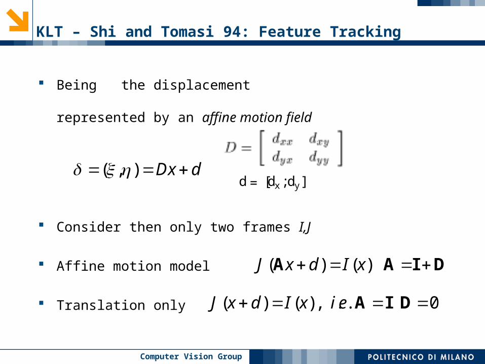
KLT – Shi and Tomasi 94: Feature Tracking
Being the displacement
represented by an affine motion field
Consider then only two frames I,J
Affine motion model
Translation only
( , ) Dx d
( ) ( )J x d I x A A I D
d = [dx;dy]
( ) ( ) , . . 0J x d I x i e A I D

Computer Vision Group
KLT – Shi and Tomasi 94: Then what Tracking actually is
Given two images I and J we are interested in determiningthe six parameters (4 affine + 2 translational motion)
Then for consequent frame a pure translation model is commonly assumed (i.e. D= Identity)

Computer Vision Group
KLT – Shi and Tomasi 94 : Dissimilarity measure
Goal : minimize dissimilarity (SSD based tracking)
A and d can be determined in a closed form (approximate solutions)
An exact solution can be obtained by iterative procedure
And also for the translation only case
Tz = a z vector of 6 unknowns, T,a can becomputed
Zd = e d vector of 2 unknowns, Z,e can becomputed

Computer Vision Group
KLT – Shi and Tomasi 94: Which are Good features?
”The right features are exactly those that make the tracker work best”
How the tracker work?
Inverting 2 matrices Z and T
Then Good features are those having the matrices Z and T well conditioned (then again eigenvalues analysis)
Thus, no a priori assumption about feature goodness Affine model also considered

Computer Vision Group
KLT – Shi and Tomasi 94 : Performances
Adjacent frames – pure displacement Z matrix Cumulative changes – Affine Transform T matrix

Computer Vision Group
KLT – Shi and Tomasi 94 : Performances
Camera moving forward 2mm per frame Affine alignment between first and last frame Stop tracking features with too large errors
Computer Vision Group
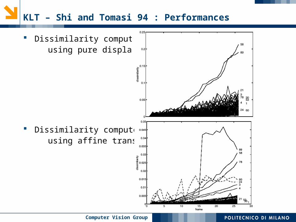
KLT – Shi and Tomasi 94 : Performances
Dissimilarity computed using pure displacement.
Dissimilarity computed using affine transforms

Computer Vision Group
A Project: Rotational Blur RemovalGiacomo Boracchi

Computer Vision Group
In each pixel the blur smears are varying
Only in trivial case of rotation axis orthogonal to image plane this can be considered circumferences
Rotational Blur

Computer Vision Group
Rotation Axis Estimation: the local blur analysis

Computer Vision Group
Rotation Axis Estimation: the voting procedure

Computer Vision Group
blurring path the set of pixels which are intersected by a viewing ray after a rotation of around the axis a
¼¼
P
C
P C´ V Vaa
circumferences Conic sections
Blurring paths
2¼

Computer Vision Group
Blur Removal: Scheme and Issues
Projection of the image on the plane orthogonal to rotation axis• In such a way the blurring paths become circumferences• The mapping (an homography) should be extremely accurate
Cartesian to Polar coordinate transform so that the blur becomes shift invariant, i.e. uniform, all the pixels blurred at the same way
Blur Inversion via Regularized Wiener Filtering (Classical Procedure)
Polar to Cartesian coordinate transform
Denoising in Cartesian domain in order to exploit image structures• Using LASIP adaptive filtering algorithms (codes)• Noise Modeling via Monte Carlo approach

Computer Vision Group
License Plate Recognition
Objective: automatically detect and recognize license plate from video sequences on a dsp-equipped camera.
YZH 4025

Computer Vision Group
License Plate Recognition – Available Projects
New Starting ProjectNew Starting Project Probably Strict DeadlinesProbably Strict Deadlines ONLY THE BRAVES!ONLY THE BRAVES!
License Plate Detection Module• Develop a module that detect the license plate in image according
to color and shape
License Plate Recognition Module• Given the license plate image, develop a module that recognize
characters (e.g. using a neural network) and provide the license number
Both projects require good C-programming skills
Coordinators: Caglioti, Gasparini, Taddei

Computer Vision Group
Computer Vision Group Team
Vincenzo Caglioti Giacomo Boracchi, Simone Gasparini, Alessandro Giusti, Pierluigi Taddei