computers and structures - sejongasel.sejong.ac.kr/images/sub04/pdf/35) on triply coupled...they...
TRANSCRIPT
Computers and Structures 88 (2010) 144–153
Contents lists available at ScienceDirect
Computers and Structures
journal homepage: www.elsevier .com/locate/compstruc
On triply coupled vibrations of axially loaded thin-walled composite beams
Thuc Phuong Vo, Jaehong Lee *, Kihak LeeDepartment of Architectural Engineering, Sejong University, 98 Kunja Dong, Kwangjin Ku, Seoul 143-747, Republic of Korea
a r t i c l e i n f o
Article history:Received 16 May 2009Accepted 25 August 2009
Keywords:Thin-walled composite beamClassical lamination theoryTriply coupled vibrationsAxial force
0045-7949/$ - see front matter � 2009 Elsevier Ltd. Adoi:10.1016/j.compstruc.2009.08.015
* Corresponding author. Tel.: +82 2 3408 3287; faxE-mail address: [email protected] (J. Lee).
a b s t r a c t
Free vibration of axially loaded thin-walled composite beams with arbitrary lay-ups is presented. Thismodel is based on the classical lamination theory, and accounts for all the structural coupling comingfrom material anisotropy. Equations of motion for flexural–torsional coupled vibration are derived fromthe Hamilton’s principle. The resulting coupling is referred to as triply coupled vibrations. A displace-ment-based one-dimensional finite element model is developed to solve the problem. Numerical resultsare obtained for thin-walled composite beams to investigate the effects of axial force, fiber orientationand modulus ratio on the natural frequencies, load–frequency interaction curves and correspondingvibration mode shapes.
� 2009 Elsevier Ltd. All rights reserved.
1. Introduction
Fiber-reinforced composite materials have been used over thepast few decades in a variety of structures. Composites have manydesirable characteristics, such as high ratio of stiffness andstrength to weight, corrosion resistance and magnetic transpar-ency. Thin-walled structural shapes made up of composite materi-als, which are usually produced by pultrusion, are beingincreasingly used in many engineering fields. However, the struc-tural behavior is very complex due to coupling effects as well aswarping-torsion and therefore, the accurate prediction of stabilitylimit state and dynamic characteristics is of the fundamentalimportance in the design of composite structures.
The theory of thin-walled members made of isotropic materialswas first developed by Vlasov [1] and Gjelsvik [2]. Up to the pres-ent, investigation into the stability and vibrational behavior ofthese members has received widespread attention and has beencarried out extensively. Closed-form solution for the flexural andtorsional natural frequencies, critical buckling loads of isotropicthin-walled bars are found in the literature (Timoshenko [3,4]and Trahair [5]). For some practical applications, earlier studieshave shown that the effect of axial force on the natural frequenciesand mode shapes is more pronounced than those of the sheardeformation and rotary inertia. Many numerical techniques havebeen used to solve the dynamic analysis of thin-walled members.One of the most effective approach is to derive the exact stiffnessmatrices based on the solution of the governing differential equa-tions of motion. Most of those studies adopted an analytical meth-od that required explicit expressions of exact displacement
ll rights reserved.
: +82 2 3408 3331.
functions for governing equations. Although a large number ofstudies have been performed on the dynamic characteristics of axi-ally loaded isotropic thin-walled beams [6–9], it should be notedthat by using this method there appear some works reported onthe free vibration of axially loaded thin-walled closed-section com-posite beams (Banerjee et al. [10–12], Li et al. [13,14] and Kaya andOzgumus [15]). For thin-walled open-section composite beams,the works of Kim et al. [16–18] deserved special attention becausethey evaluated not only the exact element stiffness matrix but alsodynamic stiffness matrix to perform the spatially coupled stabilityand vibration analysis of thin-walled composite I-beam with arbi-trary laminations. By using finite element method, Bank and Kao[19] analyzed free and forced vibration of thin-walled compositebeams. Cortinez, Machado and Piovan [20,21] presented a theoret-ical model for the dynamic analysis of thin-walled compositebeams with initial stresses. Machado et al. [22] determined the re-gions of dynamic instability of a simply supported thin-walledcomposite beam under an axial excitation. The analysis was basedon a small strain and moderate rotation theory, which was formu-lated through the adoption of a second-order displacement field. Intheir research [20–22], thin-walled composite beams for both openand closed cross-sections and the shear flexibility (bending, non-uniform warping) were incorporated. However, it was strictly validfor symmetric balanced laminates and especially orthotropic lam-inates. By using a boundary element method, Sapountzakis andTsiatas [23] solved the flexural–torsional buckling and vibrationproblems of Euler–Bernoulli composite beams with arbitrarilycross section. This method overcame the shortcoming of possiblethin tube theory solution, which its utilization had been provento be prohibitive even in thin-walled homogeneous sections.
In this paper, which is an extension of the authors’ previousworks [24–27], flexural–torsional coupled vibration of axially

T.P. Vo et al. / Computers and Structures 88 (2010) 144–153 145
loaded thin-walled composite beams with arbitrary lay-ups is pre-sented. This model is based on the classical lamination theory, andaccounts for all the structural coupling coming from the materialanisotropy. The governing differential equations of motion are de-rived from the Hamilton’s principle. A displacement-based one-dimensional finite element model is developed to solve the prob-lem. Numerical results are obtained for thin-walled compositebeams to investigate the effects of axial force, fiber orientationand modulus ratio on the natural frequencies and load–frequencyinteraction curves as well as corresponding vibration mode shapes.
2. Kinematics
The theoretical developments presented in this paper requiretwo sets of coordinate systems which are mutually interrelated.The first coordinate system is the orthogonal Cartesian coordinatesystem (x, y, z), for which the x and y axes lie in the plane of thecross section and the z axis parallel to the longitudinal axis ofthe beam. The second coordinate system is the local plate coordi-nate (n, s, z) as shown in Fig. 1, wherein the n axis is normal tothe middle surface of a plate element, the s axis is tangent to themiddle surface and is directed along the contour line of the crosssection. The (n, s, z) and (x, y, z) coordinate systems are relatedthrough an angle of orientation h. As defined in Fig. 1 a point P,called the pole, is placed at an arbitrary point xp; yp. A line throughP parallel to the z axis is called the pole axis.
To derive the analytical model for a thin-walled compositebeam, the following assumptions are made:
1. The contour of the thin wall does not deform in its own plane.2. The linear shear strain �csz of the middle surface is zero in each
element.3. The Kirchhoff–Love assumption in classical plate theory
remains valid for laminated composite thin-walled beams.4. Each laminate is thin and perfectly bonded.5. Local buckling is not considered.
According to assumption 1, the midsurface displacement com-ponents �u; �v at a point A in the contour coordinate system can beexpressed in terms of a displacements U, V of the pole P in the x,y directions, respectively, and the rotation angle U about the poleaxis,
�uðs; zÞ ¼ UðzÞ sin hðsÞ � VðzÞ cos hðsÞ �UðzÞqðsÞ ð1aÞ�vðs; zÞ ¼ UðzÞ cos hðsÞ þ VðzÞ sin hðsÞ þUðzÞrðsÞ ð1bÞ
Fig. 1. Definition of coordinates in thin-walled open sections.
These equations apply to the whole contour. The out-of-plane shelldisplacement �w can now be found from the assumption 2. For eachelement of middle surface, the shear strain become
�csz ¼@�v@zþ @
�w@s¼ 0 ð2Þ
After substituting for �v from Eq. (1) and considering the followinggeometric relations,
dx ¼ ds cos h ð3aÞdy ¼ ds sin h ð3bÞ
Eq. (2) can be integrated with respect to s from the origin to an arbi-trary point on the contour,
�wðs; zÞ ¼WðzÞ � U0ðzÞxðsÞ � V 0ðzÞyðsÞ �U0ðzÞxðsÞ ð4Þ
where differentiation with respect to the axial coordinate z is de-noted by primes (0); W represents the average axial displacementof the beam in the z direction; x and y are the coordinates of thecontour in the (x, y, z) coordinate system; and x is the so-called sec-torial coordinate or warping function given by
xðsÞ ¼Z s
s�
rðsÞds ð5aÞ
The displacement components u,v,w representing the deformationof any generic point on the profile section are given with respectto the midsurface displacements �u; �v ; �w by the assumption 3.
uðs; z; nÞ ¼ �uðs; zÞ ð6aÞ
vðs; z;nÞ ¼ �vðs; zÞ � n@�uðs; zÞ@s
ð6bÞ
wðs; z;nÞ ¼ �wðs; zÞ � n@�uðs; zÞ@z
ð6cÞ
The strains associated with the small-displacement theory of elas-ticity are given by
�s ¼ ��s þ n�js ð7aÞ�z ¼ ��z þ n�jz ð7bÞcsz ¼ �csz þ n�jsz ð7cÞ
where
��s ¼@�v@s
; ��z ¼@ �w@z
ð8aÞ
�js ¼ �@2�u@z2 ; �jz ¼ �
@2�u@z2 ; �jsz ¼ �2
@2�u@s@z
ð8bÞ
All the other strains are identically zero. In Eq. (8), ��s and �js are as-sumed to be zero. ��z; �jz and �jsz are midsurface axial strain and biax-ial curvature of the shell, respectively. The above shell strains can beconverted to beam strain components by substituting Eqs. (1), (4)and (6) into Eq. (8) as
��z ¼ ��z þ xjy þ yjx þxjx ð9aÞ�jz ¼ jy sin h� jx cos h� jxq ð9bÞ�jsz ¼ 2�vsz ¼ jsz ð9cÞ
where ��z ;jx;jy;jx and jsz are axial strain, biaxial curvatures in thex and y direction, warping curvature with respect to the shear cen-ter, and twisting curvature in the beam, respectively defined as
��z ¼W 0 ð10aÞ
jx ¼ �V 00 ð10bÞ
jy ¼ �U00 ð10cÞ
jx ¼ �U00 ð10dÞ
jsz ¼ 2U0 ð10eÞ
146 T.P. Vo et al. / Computers and Structures 88 (2010) 144–153
The resulting strains can be obtained from Eqs. (7) and (9) as
�z ¼ ��z þ ðxþ n sin hÞjy þ ðy� n cos hÞjx þ ðx� nqÞjx ð11aÞcsz ¼ njsz ð11bÞ
3. Variational formulation
The total potential energy of the system can be stated, in itsbuckled shape, as
P ¼ UþV ð12Þwhere U is the strain energy
U ¼ 12
Zvðrz�z þ rszcszÞdv ð13Þ
After substituting Eq. (11) into Eq. (13)
U ¼ 12
Zvfrz½��z þ ðxþ n sin hÞjy þ ðy� n cos hÞjx
þ ðx� nqÞjx� þ rsznjszgdv ð14Þ
The variation of strain energy can be stated as
dU ¼Z l
0ðNzd�z þMydjy þMxdjx þMxdjx þMtdjszÞdz ð15Þ
where Nz;Mx;My;Mx;Mt are axial force, bending moments in thex- and y-direction, warping moment (bimoment), and torsionalmoment with respect to the centroid, respectively, defined byintegrating over the cross-sectional area A as
Nz ¼Z
Arzdsdn ð16aÞ
My ¼Z
Arzðxþ n sin hÞdsdn ð16bÞ
Mx ¼Z
Arzðy� n cos hÞdsdn ð16cÞ
Mx ¼Z
Arzðx� nqÞdsdn ð16dÞ
Mt ¼Z
Arszndsdn ð16eÞ
The potential of in-plane loads V due to transverse deflection
V ¼ 12
Zv
�r0z ½ðu0Þ
2 þ ðv 0Þ2�dv ð17Þ
where �r0z is the averaged constant in-plane edge axial stress, de-
fined by �r0z ¼ P0=A. The variation of the potential of in-plane loads
at the centroid is expressed by substituting the assumed displace-ment field into Eq. (17) as
dV ¼Z
v
P0
A½U0dU0 þ V 0dV 0 þ ðq2 þ r2 þ 2rnþ n2ÞU0dU0
þ ðU0dU0 þ U0dU0Þ½n cos h� ðy� ypÞ� þ ðU0dV 0 þ V 0dU0Þ� ½n cos hþ ðx� xpÞ��dv ð18Þ
The kinetic energy of the system is given by
T ¼ 12
Zvqð _u2 þ _v2 þ _w2Þdv ð19Þ
where q is a density.The variation of the kinetic energy is expressed by substituting
the assumed displacement field into Eq. (19) as
dT ¼Z
vq _Ud _U þ _Vd _V þ _Wd _W þ ðq2 þ r2 þ 2rnþ n2Þ _Ud _Un
þð _Ud _U þ _Ud _UÞ½n cos h� ðy� ypÞ�
þð _Ud _V þ _Vd _UÞ½n cos hþ ðx� xpÞ�o
dv ð20Þ
In order to derive the equations of motion, Hamilton’s principle isused
dZ t2
t1
ðT�PÞdt ¼ 0 ð21Þ
Substituting Eqs. (15), (18) and (20) into Eq. (21), the followingweak statement is obtained
0 ¼Z t2
t1
Z l
0m0
_Wd _W þ ½m0_U þ ðmc þm0ypÞ _U�d _U
n
þ½m0_V þ ðms �m0xpÞ _U�d _V þ ½ðmc þm0ypÞ _U
þðms �m0xpÞ _V þ ðmp þm2 þ 2mxÞ _U�d _U
�P0½dU0ðU0 þU0ypÞ þ dV 0ðV 0 �U0xpÞ
þdU0ðU0 Ip
Aþ U0yp � V 0xpÞ� � NzdW 0 þMydU00 þMxdV 00
þMxdU00 � 2MtdU0gdzdt ð22Þ
The expressions of inertia coefficients for thin-walled compositebeams are given in Refs. [25,26].
4. Constitutive equations
The constitutive equations of a kth orthotropic lamina in thelaminate co-ordinate system of section are given by
rz
rsz
� �k
¼Q �11 Q �16
Q �16 Q �66
" #k�z
csz
� �ð23Þ
where Q �ij are transformed reduced stiffnesses. The transformed re-duced stiffnesses can be calculated from the transformed stiffnessesbased on the plane stress ðrs ¼ 0Þ and plane strain ð�s ¼ 0Þ assump-tion. More detailed explanation can be found in Ref. [28].
The constitutive equations for bar forces and bar strains are ob-tained by using Eq. (11), (16) and (24)
Nz
My
Mx
Mx
Mt
8>>>>>>>><>>>>>>>>:
9>>>>>>>>=>>>>>>>>;¼
E11 E12 E13 E14 E15
E22 E23 E24 E25
E33 E34 E35
E44 E45
sym: E55
2666666664
3777777775
��zjy
jx
jx
jsz
8>>>>>>>><>>>>>>>>:
9>>>>>>>>=>>>>>>>>;
ð24Þ
where Eij are stiffnesses of thin-walled composite beams and givenin Ref. [27].
5. Governing equations of motion
The governing equations of motion of the present study can bederived by integrating the derivatives of the varied quantities byparts and collecting the coefficients of dW ; dU; dV and dU
N0z ¼ m0€W ð25aÞ
M00y þ P0ðU00 þU00ypÞ ¼ m0
€U þ ðmc þm0ypÞ€U ð25bÞ
M00x þ P0ðV 00 �U00xpÞ ¼ m0
€V þ ðms �m0xpÞ€U ð25cÞ
M00x þ 2M0
t þ P0 U00Ip
Aþ U00yp � V 00xp
� �
¼ ðmc þm0ypÞ€U þ ðms �m0xpÞ€V þ ðmp þm2 þ 2mxÞ€U ð25dÞ
T.P. Vo et al. / Computers and Structures 88 (2010) 144–153 147
The natural boundary conditions are of the form
dW : W ¼W0 or Nz ¼ P0 ð26aÞdU : U ¼ U0 or M0
y ¼ M0y0
ð26bÞdU0 : U0 ¼ U00 or My ¼ My0
ð26cÞdV : V ¼ V0 or M0
x ¼ M0x0
ð26dÞdV 0 : V 0 ¼ V 00 or Mx ¼ Mx0 ð26eÞdU : U ¼ U0 or M0
x þ 2Mt ¼ M0x0
ð26fÞdU0 : U0 ¼ U00 or Mx ¼ Mx0 ð26gÞ
where the displacements and forces denoted by the subscript zeroare prescribed values.
By substituting Eqs. (10) and (24) into Eq. (25), the explicit formof governing equations of motion can be expressed with respect tothe laminate stiffnesses Eij as
E11W 00 � E12U000 � E13V 000 � E14U000 þ 2E15U
00 ¼ m0€W ð27aÞ
E12W 000 � E22Uiv � E23Viv � E24Uiv þ 2E25U
000 þ P0ðU00 þU00ypÞ¼ m0
€U þ ðmc þm0ypÞ€U ð27bÞ
E13W 000 � E23Uiv � E33Viv � E34Uiv þ 2E35U
000 þ P0ðV 00 �U00xpÞ¼ m0
€V þ ðms �m0xpÞ€U ð27cÞ
E14W 000 þ 2E15W 00 � E24Uiv � 2E25U000 � E34Viv � 2E35V 000
� E44Uiv þ 4E55U
00 þ P0ðU00Ip
Aþ U00yp � V 00xpÞ
¼ ðmc þm0ypÞ€U þ ðms �m0xpÞ€V þ ðmp þm2 þ 2mxÞ€U ð27dÞ
Eq. (27) is most general form for flexural–torsional coupled vibra-tion of axially loaded thin-walled composite beams, and the depen-dent variables, W, U, V and U are fully coupled. If all the couplingeffects are neglected and the cross section is symmetrical with re-spect to both x- and the y-axes, Eq. (27) can be simplified to theuncoupled differential equations as
ðEAÞcomW 00 ¼ qA €W ð28aÞ
� ðEIyÞcomUiv þ P0U00 ¼ qA€U ð28bÞ
� ðEIxÞcomViv þ P0V 00 ¼ qA€V ð28cÞ
� ðEIxÞcomUiv þ ðGJÞcom þ P0Ip
A
� �U00 ¼ qIp
€U ð28dÞ
From above equations, ðEAÞcom represents axial rigidity, ðEIxÞcom andðEIyÞcom represent flexural rigidities with respect to x- and y-axis,ðEIxÞcom represents warping rigidity, and ðGJÞcom, represents tor-sional rigidity of thin-walled composite beams, respectively, writ-ten as
ðEAÞcom ¼ E11 ð29aÞ
ðEIyÞcom ¼ E22 ð29bÞ
ðEIxÞcom ¼ E33 ð29cÞ
ðEIxÞcom ¼ E44 ð29dÞ
ðGJÞcom ¼ 4E55 ð29eÞ
It is well known that the three distinct load–frequency interactioncurves corresponding to flexural buckling and natural frequenciesin the x- and y- direction, and torsional buckling and natural fre-quency, respectively. They are given by the orthotropy solutionfor simply supported boundary conditions [29]
xxxn ¼ xxn
ffiffiffiffiffiffiffiffiffiffiffiffiffiffi1� P0
Px
sð30aÞ
xyyn¼ xyn
ffiffiffiffiffiffiffiffiffiffiffiffiffiffi1� P0
Py
sð30bÞ
xhhn ¼ xhn
ffiffiffiffiffiffiffiffiffiffiffiffiffiffi1� P0
Ph
sð30cÞ
where xxn ;xynand xhn are corresponding flexural natural frequen-
cies in the x- and y-direction and torsional natural frequency [4].
xxn ¼n2p2
l2
ffiffiffiffiffiffiffiffiffiffiffiffiffiffiffiffiðEIyÞcom
qA
sð31aÞ
xyn¼ n2p2
l2
ffiffiffiffiffiffiffiffiffiffiffiffiffiffiffiffiðEIxÞcom
qA
sð31bÞ
xhn ¼npl
ffiffiffiffiffiffiffiffiffiffiffiffiffiffiffiffiffiffiffiffiffiffiffiffiffiffiffiffiffiffiffiffiffiffiffiffiffiffiffiffiffiffiffiffiffiffiffiffiffiffiffiffiffiffiffiffiffiffiffiffiffi1
qIp
n2p2
l2 ðEIxÞcom þ ðGJÞcom
� �sð31cÞ
and Px; Py and Ph are also corresponding flexural buckling loads inthe x- and y-direction and torsional buckling load [5], respectively.
Px ¼p2ðEIyÞcom
l2 ð32aÞ
Py ¼p2ðEIxÞcom
l2 ð32bÞ
Ph ¼AIp
p2ðEIxÞcom
l2 þ ðGJÞcom
� �ð32cÞ
6. Finite element formulation
The present theory for thin-walled composite beams describedin the previous section was implemented via a displacement-basedfinite element method. The element has seven degrees of freedomat each node, three displacements W, U, V and three rotationsU0;V 0;U0 as well as one warping degree of freedom U0. The axial dis-placement W is interpolated using linear shape functions Wj,whereas the lateral and vertical displacements U, V and axial rota-tion U are interpolated using Hermite-cubic shape functions wj
associated with node j and the nodal values, respectively.
W ¼X2
j¼1
wjWj ð33aÞ
U ¼X4
j¼1
ujwj ð33bÞ
V ¼X4
j¼1
v jwj ð33cÞ
U ¼X4
j¼1
Ujwj ð33dÞ
Substituting these expressions into the weak statement in Eq. (18),the finite element model of a typical element can be expressed asthe standard eigenvalue problem
ð½K� � P0½G� �x2½M�ÞfDg ¼ f0g ð34Þ
where [K], [G] and [M] are the element stiffness matrix, the elementgeometric stiffness matrix and the element mass matrix, respec-tively. The explicit forms of [K], [G] and [M] are given in Refs.[24–27].
In Eq. (34), fDg is the eigenvector of nodal displacements corre-sponding to an eigenvalue

Structures 88 (2010) 144–153
fDg ¼ fW U V UgT ð35Þ
148 T.P. Vo et al. / Computers and
7. Numerical examples
For verification purpose, flexural–torsional buckling and vibra-tion analysis of a cantilever isotropic mono-symmetric channelsection beam (Fig. 2), with length l = 2 m under an axial force atthe centroid is performed. The material properties are assumedto be: E ¼ 0:3 GPa ;G ¼ 0:115 GPa ;q ¼ 7850 kg=m3. Ten Hermi-tian beam elements with two nodes are used in the numericalexamples. The buckling loads are evaluated and compared withnumerical results of Kim et al. [9], which is based on dynamic stiff-ness formulation and ABAQUS solutions, in Table 1. Next, the flex-ural–torsional coupled vibration analysis of axially loadedcantilever beam is analyzed. The value of 6.995N is adopted as ini-tial compressive and tensile forces, which is the half of the criticalbuckling load of the beam. The lowest four natural frequencieswith and without the axial force are presented in Table 2. Tables1 and 2 show that the present results are in a good agreement withthose by Kim et al. [9].
The next example demonstrates the accuracy and validity ofthis study for thin-walled composite beams. The symmetric an-gle-ply I-beams with various fiber angles and two boundary con-ditions are considered. Following dimensions for I-beam are used:both of flanges width and web height are 50 mm. The flanges andweb are assumed to be symmetrically laminated with respect toits midplane and made of sixteen layers with each layer0.13mm in thickness. All computations are carried out with the
Table 2Effect of axial force on the first four natural frequencies of a cantilever isotropic mono-sy
Mode P = 6.995 N (compression) P = 0 (n
Ref. [9] Present Ref. [9
1 0.118 0.108 0.1642 0.570 0.570 0.5803 0.825 0.830 0.8414 1.002 1.003 1.036
Fig. 2. Isotropic mono-symmetric channel section for verification.
Table 1Flexural–torsional bucking loads of a cantilever isotropic mono-symmetric channelsection beam (N).
Mode Kim et al. [9] Present
ABAQUS Theory
1 14.001 13.800 13.9932 113.100 112.550 114.3463 190.080 191.840 191.9564 256.670 258.540 263.649
following material properties: E1 ¼ 53:78 GPa, E2 ¼ 17:93 GPa,G12 ¼ 8:96 GPa, m12 ¼ 0:25, q ¼ 1968:9 kg=m3, where subscripts‘1’ and ‘2’ correspond to directions parallel and perpendicular tofiber direction, respectively. The critical buckling loads of a canti-lever composite I-beam with length l = 1 m and the first six natu-ral frequencies of a simply supported one with length l = 2 m aregiven in Tables 3 and 4. The present solution again indicates goodagreement with the analytical approach by Kim et al. [17,18] andRoberts [30] for all lamination schemes considered. The effect ofaxial force on the fundamental natural frequency of a cantileverand simply supported beam with various fiber angles is exhibitedin Figs. 3 and 4. For simply supported boundary condition, whenfiber angle is equal to 0�, 30� and 60�, at about P ¼ 5:75�103 N; 3:86� 103 N and 2:11� 103 N, respectively, the fundamen-tal natural frequencies become zero which implies that at theseloads, the critical bucklings occur as a degenerate case of naturalvibration at zero frequency. Figs. 3 and 4 also explain the dualitybetween flexural–torsional buckling and natural frequency.
A simply supported composite I-beam with length l = 8 m isconsidered to investigate the effects of axial force, fiber orientationon the natural frequencies and load–frequency interaction curvesas well as corresponding vibration mode shapes. The geometryand stacking sequences of the I-section are shown in Fig. 5, andthe following engineering constants are used
E1=E2 ¼ 25; G12=E2 ¼ 0:6; m12 ¼ 0:25 ð36Þ
For convenience, the following nondimensional axial force and nat-ural frequency are used
P ¼ Pl2
b33tE2
ð37Þ
x ¼ xl2
b3
ffiffiffiffiffiqE2
rð38Þ
The top and bottom flanges are angle-ply laminates ½h=� h�, and theweb laminates are assumed to be undirectional (Fig. 5a). All thecoupling stiffnesses are zero, but E35 does not vanish due to unsym-metric stacking sequence of the flanges. The lowest three naturalfrequencies with and without the effect of axial force are given inTable 5. The critical buckling loads and the natural frequencieswithout axial force agree completely with those of previous papers[24,25], as expected. The change in the natural frequencies due to
mmetric channel section beam (rad/s).
o axial force) P = �6.995 N (tension)
] Present Ref. [9] Present
0.166 0.197 0.2060.582 0.589 0.5930.849 0.854 0.8641.045 1.072 1.087
Table 3Critical bucking loads (N) of a cantilever composite I-beam with symmetric angle-plylaminates ½�h�4s in the flanges and web.
Lay-ups Kim et al. [17] Present
ABAQUS Theory
[0]16 5720.0 5755.2 5741.5½15=� 15�4s 5174.0 5199.8 5189.0½30=� 30�4s 3848.0 3861.0 3854.5½45=� 45�4s 2665.0 2672.7 2668.4½60=� 60�4s 2119.0 2114.7 2111.3½75=� 75�4s 1950.0 1948.3 1945.1

Table 4Natural frequencies (Hz) of a simply supported composite I-beam with symmetric angle-ply laminates ½�h�4s in the flanges and web.
Lay-ups Formulation Mode
1 2 3 4 5 6
[0]16 Ref. [18] 24.194 35.233 45.235 96.726 109.441 180.616Ref. [30] 24.198 35.240 45.262 96.792 109.516 181.048Present 24.198 35.229 45.262 96.792 109.485 181.048
[15/�15]4s Ref. [18] 22.997 36.247 42.996 91.940 107.655 171.678Ref. [30] 23.001 36.253 43.022 92.003 107.729 172.089Present 23.001 36.124 43.022 92.003 107.538 172.089
[30/�30]4s Ref. [18] 19.816 37.051 37.864 79.225 102.159 147.938Ref. [30] 19.820 37.073 37.871 79.279 102.229 148.291Present 19.820 36.848 37.073 79.279 100.710 148.290
[45/�45]4s Ref. [18] 16.487 30.827 37.915 65.916 94.884 123.085Ref. [30] 16.490 30.845 37.921 65.961 94.949 123.380Present 16.490 30.845 35.171 65.961 90.605 123.379
[60/�60]4s Ref. [18] 14.666 27.420 35.372 58.633 87.051 109.484Ref. [30] 14.668 27.437 35.378 58.673 87.111 109.746Present 14.668 27.437 32.254 58.673 82.109 109.747
[75/�75]4s Ref. [18] 14.077 26.319 31.313 56.278 79.330 105.087Ref. [30] 14.079 26.335 31.318 56.316 79.385 105.339Present 14.079 26.335 29.985 56.316 77.289 105.338
[90/�90]4s Ref. [18] 13.970 26.119 29.175 55.850 75.767 104.287Ref. [30] 13.972 26.134 29.180 55.880 75.819 104.537Present 13.972 26.135 29.172 55.888 75.798 104.538
Fig. 3. Effect of axial force on the fundamental natural frequency with the fiberangle 0�, 30� and 60� in the flanges and web of a simply supported composite beam.
Fig. 4. Effect of axial force on the fundamental natural frequency with the fiberangle 0�, 30� and 60� in the flanges and web of a cantilever composite beam.
Fig. 5. Geometry and stacking sequences of thin-walled composite I-beam.
T.P. Vo et al. / Computers and Structures 88 (2010) 144–153 149
axial force is significant for all fiber angles. It is noticed that the nat-ural frequencies diminish as the axial force changes from tensionðP ¼ �0:5PcrÞ to compression ðP ¼ 0:5PcrÞ. It reveals that the tensionforce has a stiffening effect while the compressive force has a soft-ening effect on the natural frequencies. The lowest three load–fre-quency interaction curves with the fiber angle h ¼ 0� and 30�obtained by finite element analysis and the orthotropy solution,which neglects the coupling effects of E35 from Eqs. (30a)–(30c),are plotted in Figs. 6 and 7. For unidirectional fiber direction, thelowest load–frequency interaction curve exactly corresponds tothe first flexural in x-direction and the larger ones correspond tothe torsional mode and the second flexural in x-direction of theorthotropy solution, respectively. As the fiber angle increases, thevibration mode 1 and 3 are the first and second flexural mode inx-direction. Thus, the othotropy solution and the finite elementanalysis are identical. However, the vibration mode 2 exhibits dou-ble coupling (the first flexural mode in y-direction and torsionalmode). Due to the small coupling stiffnesses E35, this mode becomes
predominantly the torsional mode, with a little contribution fromflexural mode. Therefore, the results by the finite element analy-sis ðx2 � P2Þ and orthotropy solution ðxh1 � Ph1 Þ show slight
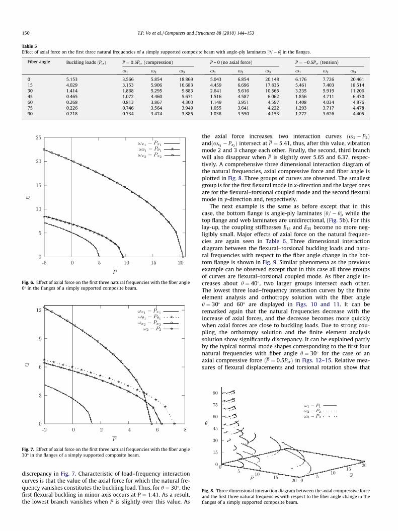
Table 5Effect of axial force on the first three natural frequencies of a simply supported composite beam with angle-ply laminates ½h=� h� in the flanges.
Fiber angle Buckling loads ðPcrÞ P ¼ 0:5Pcr (compression) P = 0 (no axial force) P ¼ �0:5Pcr (tension)
x1 x2 x3 x1 x2 x3 x1 x2 x3
0 5.153 3.566 5.854 18.869 5.043 6.854 20.148 6.176 7.726 20.46115 4.029 3.153 5.906 16.683 4.459 6.696 17.835 5.461 7.403 18.51430 1.414 1.868 5.295 9.883 2.641 5.616 10.565 3.235 5.919 11.20645 0.465 1.072 4.460 5.671 1.516 4.587 6.062 1.856 4.711 6.43060 0.268 0.813 3.867 4.300 1.149 3.951 4.597 1.408 4.034 4.87675 0.226 0.746 3.564 3.949 1.055 3.641 4.222 1.293 3.717 4.47890 0.218 0.734 3.474 3.885 1.038 3.550 4.153 1.272 3.626 4.405
Fig. 6. Effect of axial force on the first three natural frequencies with the fiber angle0� in the flanges of a simply supported composite beam.
Fig. 7. Effect of axial force on the first three natural frequencies with the fiber angle30� in the flanges of a simply supported composite beam.
Fig. 8. Three dimensional interaction diagram between the axial compressive forceand the first three natural frequencies with respect to the fiber angle change in theflanges of a simply supported composite beam.
150 T.P. Vo et al. / Computers and Structures 88 (2010) 144–153
discrepancy in Fig. 7. Characteristic of load–frequency interactioncurves is that the value of the axial force for which the natural fre-quency vanishes constitutes the buckling load. Thus, for h ¼ 30�, thefirst flexural buckling in minor axis occurs at P ¼ 1:41. As a result,the lowest branch vanishes when P is slightly over this value. As
the axial force increases, two interaction curves ðx2 � P2Þandðxx2 � Px2 Þ intersect at P ¼ 5:41, thus, after this value, vibrationmode 2 and 3 change each other. Finally, the second, third branchwill also disappear when P is slightly over 5.65 and 6.37, respec-tively. A comprehensive three dimensional interaction diagram ofthe natural frequencies, axial compressive force and fiber angle isplotted in Fig. 8. Three groups of curves are observed. The smallestgroup is for the first flexural mode in x-direction and the larger onesare for the flexural–torsional coupled mode and the second flexuralmode in y-direction and, respectively.
The next example is the same as before except that in thiscase, the bottom flange is angle-ply laminates ½h=� h�, while thetop flange and web laminates are unidirectional, (Fig. 5b). For thislay-up, the coupling stiffnesses E15 and E35 become no more neg-ligibly small. Major effects of axial force on the natural frequen-cies are again seen in Table 6. Three dimensional interactiondiagram between the flexural–torsional buckling loads and natu-ral frequencies with respect to the fiber angle change in the bot-tom flange is shown in Fig. 9. Similar phenomena as the previousexample can be observed except that in this case all three groupsof curves are flexural–torsional coupled mode. As fiber angle in-creases about h ¼ 40�, two larger groups intersect each other.The lowest three load–frequency interaction curves by the finiteelement analysis and orthotropy solution with the fiber angleh ¼ 30� and 60� are displayed in Figs. 10 and 11. It can beremarked again that the natural frequencies decrease with theincrease of axial forces, and the decrease becomes more quicklywhen axial forces are close to buckling loads. Due to strong cou-pling, the orthotropy solution and the finite element analysissolution show significantly discrepancy. It can be explained partlyby the typical normal mode shapes corresponding to the first fournatural frequencies with fiber angle h ¼ 30� for the case of anaxial compressive force ðP ¼ 0:5PcrÞ in Figs. 12–15. Relative mea-sures of flexural displacements and torsional rotation show that
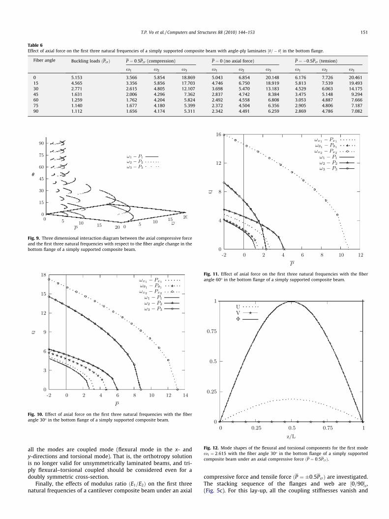
Table 6Effect of axial force on the first three natural frequencies of a simply supported composite beam with angle-ply laminates ½h=� h� in the bottom flange.
Fiber angle Buckling loads ðPcrÞ P ¼ 0:5Pcr (compression) P ¼ 0 (no axial force) P ¼ �0:5Pcr (tension)
x1 x2 x3 x1 x2 x3 x1 x2 x3
0 5.153 3.566 5.854 18.869 5.043 6.854 20.148 6.176 7.726 20.46115 4.565 3.356 5.856 17.703 4.746 6.750 18.919 5.813 7.539 19.49330 2.771 2.615 4.805 12.107 3.698 5.470 13.183 4.529 6.063 14.17545 1.631 2.006 4.296 7.362 2.837 4.742 8.384 3.475 5.148 9.29460 1.259 1.762 4.204 5.824 2.492 4.558 6.808 3.053 4.887 7.66675 1.140 1.677 4.180 5.399 2.372 4.504 6.356 2.905 4.806 7.18790 1.112 1.656 4.174 5.311 2.342 4.491 6.259 2.869 4.786 7.082
Fig. 12. Mode shapes of the flexural and torsional components for the first modex1 ¼ 2:615 with the fiber angle 30� in the bottom flange of a simply supportedcomposite beam under an axial compressive force ðP ¼ 0:5PcrÞ.
Fig. 11. Effect of axial force on the first three natural frequencies with the fiberangle 60� in the bottom flange of a simply supported composite beam.
Fig. 10. Effect of axial force on the first three natural frequencies with the fiberangle 30� in the bottom flange of a simply supported composite beam.
Fig. 9. Three dimensional interaction diagram between the axial compressive forceand the first three natural frequencies with respect to the fiber angle change in thebottom flange of a simply supported composite beam.
T.P. Vo et al. / Computers and Structures 88 (2010) 144–153 151
all the modes are coupled mode (flexural mode in the x- andy-directions and torsional mode). That is, the orthotropy solutionis no longer valid for unsymmetrically laminated beams, and tri-ply flexural–torsional coupled should be considered even for adoubly symmetric cross-section.
Finally, the effects of modulus ratio ðE1=E2Þ on the first threenatural frequencies of a cantilever composite beam under an axial
compressive force and tensile force ðP ¼ �0:5PcrÞ are investigated.The stacking sequence of the flanges and web are ½0=90�s,(Fig. 5c). For this lay-up, all the coupling stiffnesses vanish and

Fig. 13. Mode shapes of the flexural and torsional components for the second modex2 ¼ 4:805 with the fiber angle 30� in the bottom flange of a simply supportedcomposite beam under an axial compressive force ðP ¼ 0:5PcrÞ.
Fig. 14. Mode shapes of the flexural and torsional components for the third modex3 ¼ 12:107 with the fiber angle 30� in the bottom flange of a simply supportedcomposite beam under an axial compressive force ðP ¼ 0:5PcrÞ.
Fig. 15. Mode shapes of the flexural and torsional components for the fourth modex4 ¼ 16:221 with the fiber angle 30� in the bottom flange of a simply supportedcomposite beam under an axial compressive force ðP ¼ 0:5PcrÞ.
Fig. 16. Variation of the first three natural frequencies with respect to modulusratio change of a cantilever composite beam under an axial compressive forceðP ¼ 0:5PcrÞ and tensile force ðP ¼ �0:5PcrÞ.
152 T.P. Vo et al. / Computers and Structures 88 (2010) 144–153
thus, the three distinct vibration mode, flexural vibration in the x-and y-direction and torsional vibration are identified. It isobserved from Fig. 16 that the natural frequencies xxx1 ;xhh1 andxxx2 increase with increasing orthotropy ðE1=E2Þ for two casesconsidered.
8. Concluding remarks
An analytical model is developed to study the flexural–torsionalcoupled vibration of thin-walled composite beams with arbitrarylay-ups under a constant axial force. This model is capable of pre-dicting accurately the natural frequencies and load–frequencyinteraction curves as well as corresponding vibration mode shapesfor various configurations. To formulate the problem, a one-dimen-sional displacement-based finite element method is employed. All
of the possible vibration mode shapes including the flexural modein the x- and y-direction and the torsional mode, and triply coupledflexural–torsional mode are included in the analysis. The presentmodel is found to be appropriate and efficient in analyzing freevibration problem of thin-walled composite beams under a con-stant axial force.
Acknowledgments
The support of the research reported here by a grant (code#06 R&D B03) from Cutting-edge Urban Development Programfunded by the Ministry of Land, Transport and Maritime Affairsof Korea Government is gratefully acknowledged. The authorsalso would like to thank the anonymous reviewers for their sug-gestions and comments in improving the standard of themanuscript.

T.P. Vo et al. / Computers and Structures 88 (2010) 144–153 153
References
[1] Vlasov VZ. Thin walled elastic beams. Jerusalem: Israel Program for ScientificTranslation; 1961.
[2] Gjelsvik A. The theory of thin-walled bars. New York: John Wiley and Sons Inc.;1981.
[3] Timoshenko SP, Gere JM. Theory of elastic stability. New York: McGraw-Hill; 1961.[4] Timoshenko SP, Young DH, Weaver W. Vibration problems in engineering. New
York: Wiley; 1974.[5] Trahair NS. Flexural–torsional buckling of structures. London: CRC Press; 1993.[6] Leung AYT. Dynamic stiffness analysis of thin-walled structures. Thin-Walled
Struct 1992;14(3):209–22.[7] Leung AYT. Exact dynamic stiffness for axial-torsional buckling of structural
frames. Thin-Walled Struct 2008;46(1):1–10.[8] Kim MY, Yun HT, Kim NI. Exact dynamic and static element stiffness matrices
of nonsymmetric thin-walled beam-columns. Comput Struct2003;81(14):1425–48.
[9] Kim NI, Fu CC, Kim MY. Stiffness matrices for flexural–torsional/lateralbuckling and vibration analysis of thin-walled beam. J Sound Vib2007;299(4–5):739–56.
[10] Banerjee JR, Williams FW. Exact dynamic stiffness matrix for compositeTimoshenko beams with applications. J Sound Vib 1996;194(4):573–85.
[11] Banerjee JR. Free vibration of axially loaded composite Timoshenko beamsusing the dynamic stiffness matrix method. Comput Struct1998;69(2):197–208.
[12] Banerjee JR, Su H. Dynamic stiffness formulation and free vibration analysis ofa spinning composite beam. Comput Struct 2006;84(19–20):1208–14.
[13] Li J, Shen R, Jin X. Bending–torsional coupled dynamic response of axiallyloaded composite Timosenko thin-walled beam with closed cross-section.Compos Struct 2004;64(1):23–35.
[14] Li J, Wu G, Shen R, Hua H. Stochastic bending–torsion coupled response ofaxially loaded slender composite thin-walled beams with closed cross-sections. Int J Mech Sci 2005;47(1):134–55.
[15] Kaya MO, Ozgumus OO. Flexural–torsional-coupled vibration analysis ofaxially loaded closed-section composite Timoshenko beam by using DTM. JSound Vib 2007;306(3–5):495–506.
[16] Kim NI, Shin DK, Kim MY. Improved flexural–torsional stability analysis ofthin-walled composite beam and exact stiffness matrix. Int J Mech Sci2007;49(8):950–69.
[17] Kim NI, Shin DK, Kim MY. Flexural–torsional buckling loads for spatiallycoupled stability analysis of thin-walled composite columns. Adv Eng Softw2008;39(12):949–61.
[18] Kim NI, Shin DK, Park YS. Dynamic stiffness matrix of thin-walled composite I-beam with symmetric and arbitrary laminations. J Sound Vib 2008;318(1–2):364–88.
[19] Bank LC, Kao CH. Dynamic response of thin-walled composite materialTimoshenko beams. J Energ Resour 1990;112(2):149–54.
[20] Cortinez VH, Piovan MT. Vibration and buckling of composite thin-walledbeams with shear deformability. J Sound Vib 2002;258(4–5):701–23.
[21] Machado SP, Cortinez VH. Free vibration of thin-walled composite beams withstatic initial stresses and deformations. Eng Struct 2007;29(3):372–82.
[22] Machado SP, Filipich CP, Cortinez VH. Parametric vibration of thin-walledcomposite beams with shear deformation. J Sound Vib 2007;305(4–5):563–81.
[23] Sapountzakis EJ, Tsiatas GC. Flexural–torsional buckling and vibration analysisof composite beams. Comput Mater Con 2007;6(2):103–15.
[24] Lee J, Kim S. Flexural–torsional buckling of thin-walled I-section composites.Comput Struct 2001;79(10):987–95.
[25] Lee J, Kim S. Free vibration of thin-walled composite beams with I-shapedcross-sections. Compos Struct 2002;55(2):205–15.
[26] Lee J, Kim S. Flexural–torsional coupled vibration of thin-walled compositebeams with channel sections. Comput Struct 2002;80(2):133–44.
[27] Lee J, Lee S. Flexural–torsional behavior of thin-walled composite beams. Thin-Walled Struct 2004;42(9):1293–305.
[28] Jones RM. Mechanics of composite materials. New York: HemispherePublishing Corp.; 1975.
[29] Mohri F, Azrar L, Potier-Ferry M. Vibration analysis of buckled thin-walledbeams with open sections. J Sound Vib 2004;275(1–2):434–46.
[30] Roberts TM. Natural frequencies of thin-walled bars of open cross-section. JStruct Eng 1987;112(10):1584–93.