computing platform
TRANSCRIPT
UnifiedComputingPlatform &Wireless Routers
Product Selection Guide
SDKSerial Device ServersModbus GatewaysProtocol Gateways
2021/2022
2
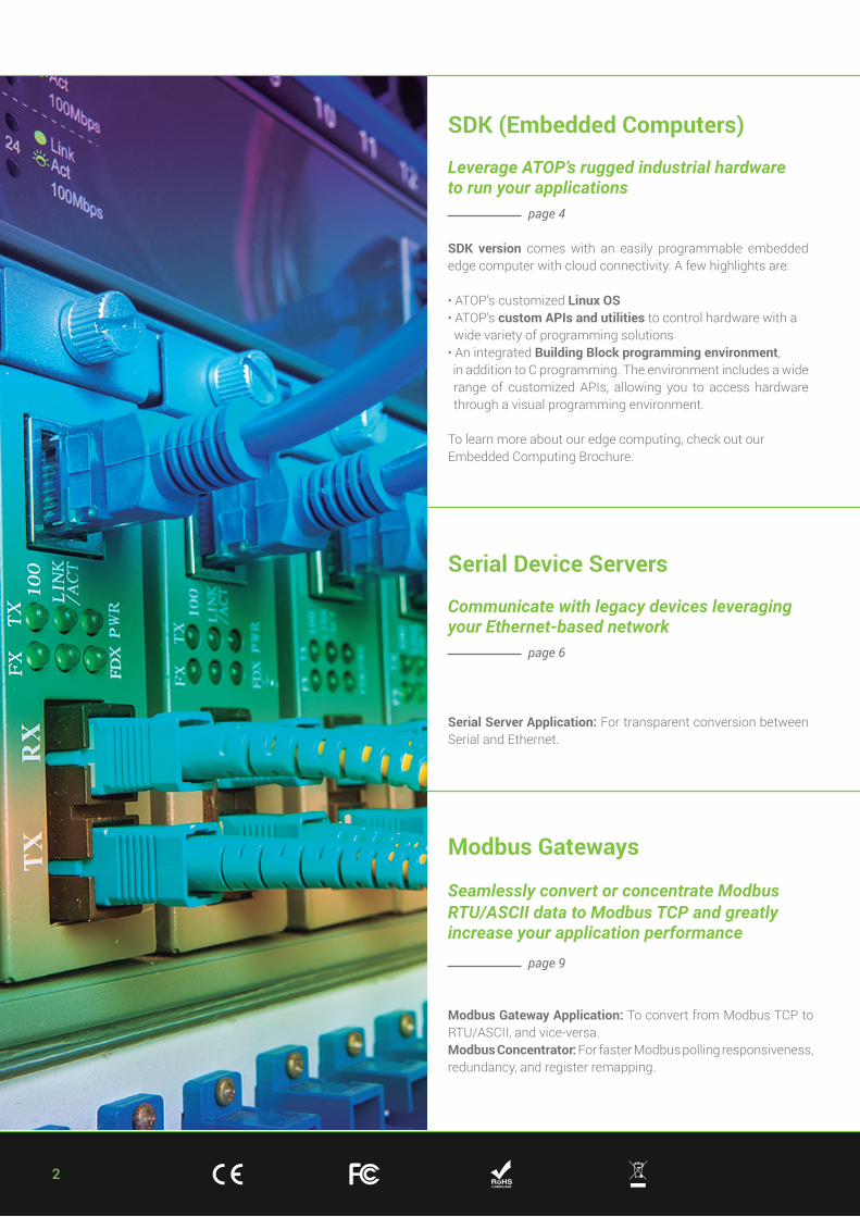
SDK (Embedded Computers)
Leverage ATOP’s rugged industrial hardware to run your applications page 4
SDK version comes with an easily programmable embedded edge computer with cloud connectivity. A few highlights are:
• ATOP’s customized Linux OS• ATOP’s custom APIs and utilities to control hardware with a wide variety of programming solutions• An integrated Building Block programming environment, in addition to C programming. The environment includes a wide range of customized APIs, allowing you to access hardware through a visual programming environment.
To learn more about our edge computing, check out our Embedded Computing Brochure.
Modbus Gateways
Seamlessly convert or concentrate ModbusRTU/ASCII data to Modbus TCP and greatly increase your application performance page 9
Modbus Gateway Application: To convert from Modbus TCP to RTU/ASCII, and vice-versa.Modbus Concentrator: For faster Modbus polling responsiveness, redundancy, and register remapping.
Serial Device Servers
Communicate with legacy devices leveraging your Ethernet-based network page 6
Serial Server Application: For transparent conversion between Serial and Ethernet.

3+ 886 - 3 - 5508137 + 886 - 3 - 5508131
Wireless Routers
Connectivity for seamless Wi-Fi mesh communication and mobile 4G/5G high-performance throughput page 17
Application: Secure your own internal link and provide cloud service through mobile 4G/5G connectivity.
Protocol Gateways for Smart Grid and Substations
Use ATOP to integrate legacy substation devices into newer networks, or vice-versa page 12
Protocol Gateway: For advanced protocol conversion applications, such as Substation and Industrial scenarios.
4
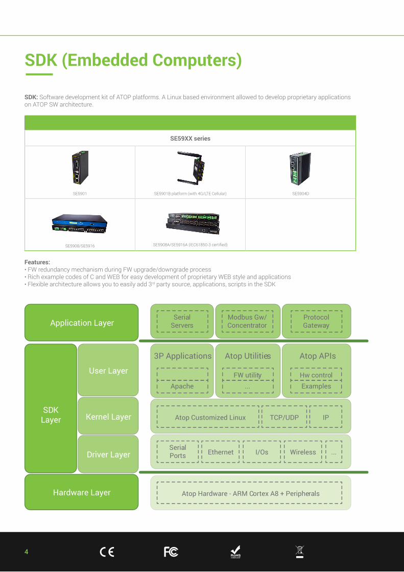
Hardware Layer
Application Layer
Atop Hardware - ARM Cortex A8 + Peripherals
SDKLayer
Driver Layer
Kernel Layer
User Layer
SerialPorts Ethernet I/Os Wireless ...
Atop Customized Linux TCP/UDP
Apache
3P Applications Atop Utilities Atop APIs
SerialServers
Modbus Gw/Concentrator
ProtocolGateway
FW utility...
Hw controlExamples
IP
SDK (Embedded Computers)
SDK: Software development kit of ATOP platforms. A Linux based environment allowed to develop proprietary applications on ATOP SW architecture.
Features:• FW redundancy mechanism during FW upgrade/downgrade process• Rich example codes of C and WEB for easy development of proprietary WEB style and applications• Flexible architecture allows you to easily add 3rd party source, applications, scripts in the SDK
SE59XX series
SE5901 SE5901B platform (with 4G/LTE Cellular) SE5904D
SE5908/SE5916 SE5908A/SE5916A (IEC61850-3 certified)
5+ 886 - 3 - 5508137 + 886 - 3 - 5508131
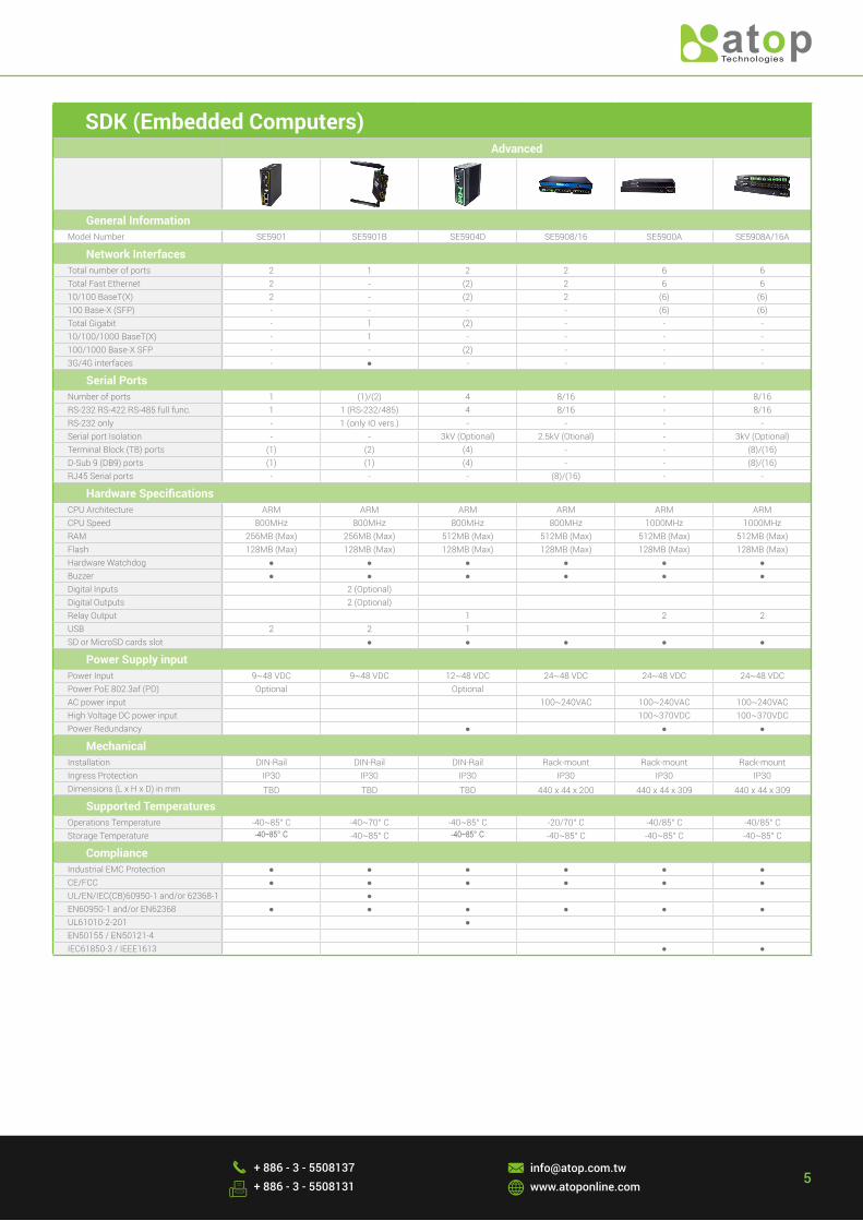
SDK (Embedded Computers)Advanced
General InformationModel Number SE5901 SE5901B SE5904D SE5908/16 SE5900A SE5908A/16A
Network InterfacesTotal number of ports 2 1 2 2 6 6Total Fast Ethernet 2 - (2) 2 6 610/100 BaseT(X) 2 - (2) 2 (6) (6)100 Base-X (SFP) - - - - (6) (6)Total Gigabit - 1 (2) - - -10/100/1000 BaseT(X) - 1 - - - -100/1000 Base-X SFP - - (2) - - -3G/4G interfaces - ● - - - -
Serial PortsNumber of ports 1 (1)/(2) 4 8/16 - 8/16RS-232 RS-422 RS-485 full func. 1 1 (RS-232/485) 4 8/16 - 8/16RS-232 only - 1 (only IO vers.) - - - -Serial port Isolation - - 3kV (Optional) 2.5kV (Otional) - 3kV (Optional)Terminal Block (TB) ports (1) (2) (4) - - (8)/(16)D-Sub 9 (DB9) ports (1) (1) (4) - - (8)/(16)RJ45 Serial ports - - - (8)/(16) - -
Hardware SpecificationsCPU Architecture ARM ARM ARM ARM ARM ARMCPU Speed 800MHz 800MHz 800MHz 800MHz 1000MHz 1000MHzRAM 256MB (Max) 256MB (Max) 512MB (Max) 512MB (Max) 512MB (Max) 512MB (Max)Flash 128MB (Max) 128MB (Max) 128MB (Max) 128MB (Max) 128MB (Max) 128MB (Max)Hardware Watchdog ● ● ● ● ● ●Buzzer ● ● ● ● ● ●Digital Inputs - 2 (Optional) - - - -Digital Outputs - 2 (Optional) - - - -Relay Output - - 1 - 2 2USB 2 2 1 - - -SD or MicroSD cards slot - ● ● ● ● ●
Power Supply inputPower Input 9~48 VDC 9~48 VDC 12~48 VDC 24~48 VDC 24~48 VDC 24~48 VDCPower PoE 802.3af (PD) Optional - Optional - - -AC power input - -- - 100~240VAC 100~240VAC 100~240VACHigh Voltage DC power input - - - - 100~370VDC 100~370VDCPower Redundancy - - ● - ● ●
MechanicalInstallation DIN-Rail DIN-Rail DIN-Rail Rack-mount Rack-mount Rack-mountIngress Protection IP30 IP30 IP30 IP30 IP30 IP30Dimensions (L x H x D) in mm TBD TBD TBD 440 x 44 x 200 440 x 44 x 309 440 x 44 x 309
Supported TemperaturesOperations Temperature -40~85° C -40~70° C -40~85° C -20/70° C -40/85° C -40/85° C Storage Temperature -40~85° C -40~85° C -40~85° C -40~85° C -40~85° C -40~85° C
ComplianceIndustrial EMC Protection ● ● ● ● ● ●CE/FCC ● ● ● ● ● ●UL/EN/IEC(CB)60950-1 and/or 62368-1 - ● - - - -EN60950-1 and/or EN62368 ● ● ● ● ● ●UL61010-2-201 - - ● - - -EN50155 / EN50121-4 - - - - - -IEC61850-3 / IEEE1613 - - - - ● ●
6
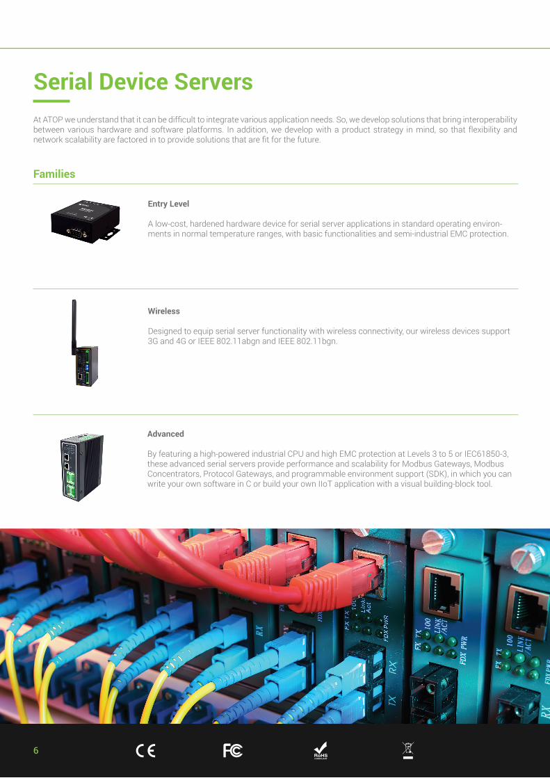
At ATOP we understand that it can be difficult to integrate various application needs. So, we develop solutions that bring interoperability between various hardware and software platforms. In addition, we develop with a product strategy in mind, so that flexibility and network scalability are factored in to provide solutions that are fit for the future.
Entry Level
A low-cost, hardened hardware device for serial server applications in standard operating environ-ments in normal temperature ranges, with basic functionalities and semi-industrial EMC protection.
Wireless
Designed to equip serial server functionality with wireless connectivity, our wireless devices support 3G and 4G or IEEE 802.11abgn and IEEE 802.11bgn.
Advanced
By featuring a high-powered industrial CPU and high EMC protection at Levels 3 to 5 or IEC61850-3, these advanced serial servers provide performance and scalability for Modbus Gateways, Modbus Concentrators, Protocol Gateways, and programmable environment support (SDK), in which you can write your own software in C or build your own IIoT application with a visual building-block tool.
Serial Device Servers
Families
7+ 886 - 3 - 5508137 + 886 - 3 - 5508131
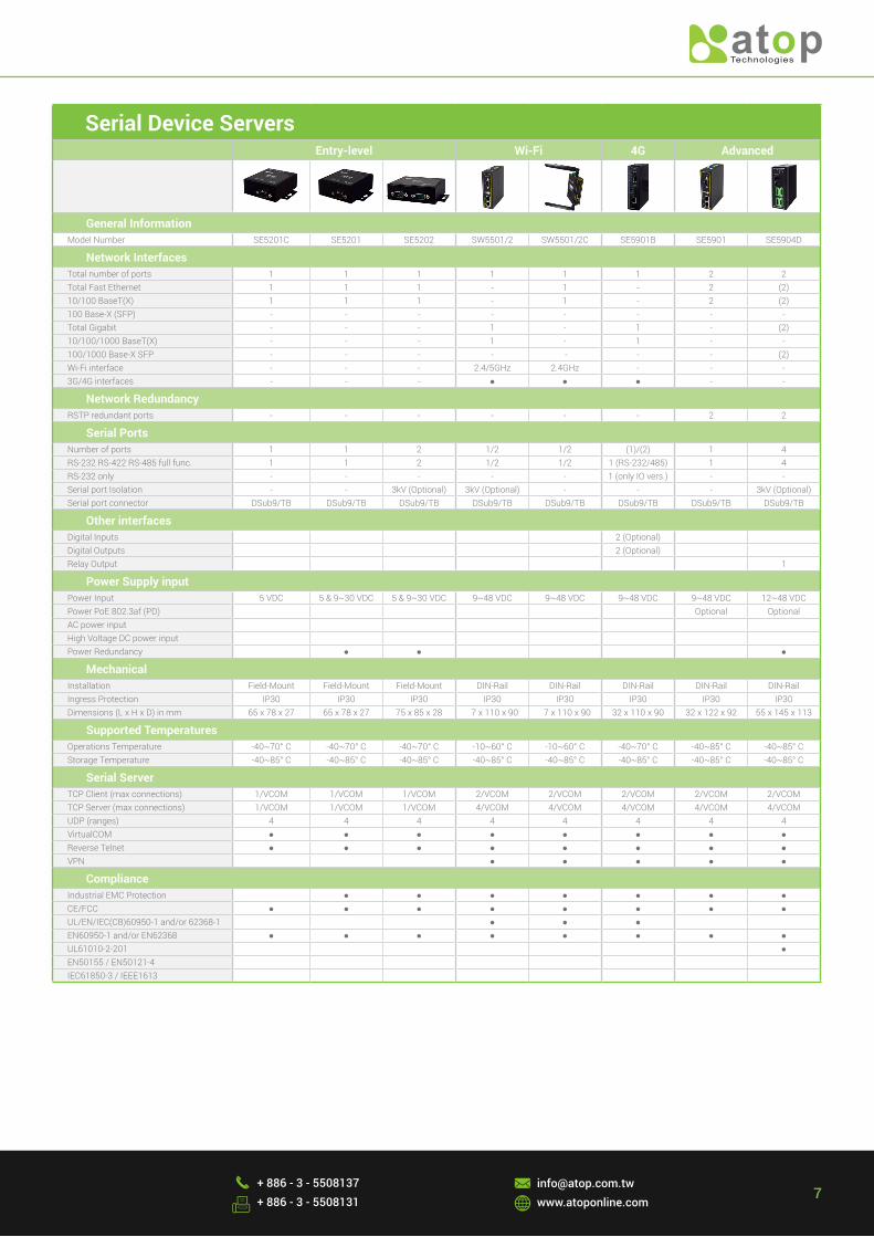
Serial Device ServersEntry-level Wi-Fi 4G Advanced
General InformationModel Number SE5201C SE5201 SE5202 SW5501/2 SW5501/2C SE5901B SE5901 SE5904D
Network InterfacesTotal number of ports 1 1 1 1 1 1 2 2Total Fast Ethernet 1 1 1 - 1 - 2 (2)10/100 BaseT(X) 1 1 1 - 1 - 2 (2)100 Base-X (SFP) - - - - - - - -Total Gigabit - - - 1 - 1 - (2)10/100/1000 BaseT(X) - - - 1 - 1 - -100/1000 Base-X SFP - - - - -- - - (2)Wi-Fi interface - - - 2.4/5GHz 2.4GHz - - -3G/4G interfaces - - - ● ● ● - -
Network RedundancyRSTP redundant ports - - - - - - 2 2
Serial PortsNumber of ports 1 1 2 1/2 1/2 (1)/(2) 1 4RS-232 RS-422 RS-485 full func. 1 1 2 1/2 1/2 1 (RS-232/485) 1 4RS-232 only - - - - - 1 (only IO vers.) - -Serial port Isolation - - 3kV (Optional) 3kV (Optional) - - - 3kV (Optional)Serial port connector DSub9/TB DSub9/TB DSub9/TB DSub9/TB DSub9/TB DSub9/TB DSub9/TB DSub9/TB
Other interfacesDigital Inputs 2 (Optional)Digital Outputs 2 (Optional)Relay Output 1
Power Supply inputPower Input 5 VDC 5 & 9~30 VDC 5 & 9~30 VDC 9~48 VDC 9~48 VDC 9~48 VDC 9~48 VDC 12~48 VDCPower PoE 802.3af (PD) Optional OptionalAC power inputHigh Voltage DC power inputPower Redundancy - ● ● ●
MechanicalInstallation Field-Mount Field-Mount Field-Mount DIN-Rail DIN-Rail DIN-Rail DIN-Rail DIN-RailIngress Protection IP30 IP30 IP30 IP30 IP30 IP30 IP30 IP30Dimensions (L x H x D) in mm 65 x 78 x 27 65 x 78 x 27 75 x 85 x 28 47 x 110 x 90 47 x 110 x 90 32 x 110 x 90 32 x 122 x 92 55 x 145 x 113
Supported TemperaturesOperations Temperature -40~70° C -40~70° C -40~70° C -10~60° C -10~60° C -40~70° C -40~85° C -40~85° C Storage Temperature -40~85° C -40~85° C -40~85° C -40~85° C -40~85° C -40~85° C -40~85° C -40~85° C
Serial ServerTCP Client (max connections) 1/VCOM 1/VCOM 1/VCOM 2/VCOM 2/VCOM 2/VCOM 2/VCOM 2/VCOMTCP Server (max connections) 1/VCOM 1/VCOM 1/VCOM 4/VCOM 4/VCOM 4/VCOM 4/VCOM 4/VCOMUDP (ranges) 4 4 4 4 4 4 4 4VirtualCOM ● ● ● ● ● ● ● ●Reverse Telnet ● ● ● ● ● ● ● ●VPN ● ● ● ● ●
ComplianceIndustrial EMC Protection ● ● ● ● ● ● ●CE/FCC ● ● ● ● ● ● ● ●UL/EN/IEC(CB)60950-1 and/or 62368-1 ● ● ●EN60950-1 and/or EN62368 ● ● ● ● ● ● ● ●UL61010-2-201 ●EN50155 / EN50121-4IEC61850-3 / IEEE1613

8
Serial Device ServersAdvanced IP68
General InformationModel Number SE5908 SE5916 SE5908A SE5916A SE8502
Network InterfacesTotal number of ports 2 2 6 6 1Total Fast Ethernet 2 2 6 6 110/100 BaseT(X) 2 2 (6) (6) 1 (M12)100 Base-X (SFP) - - (6) (6) -Total Gigabit - - - - -10/100/1000 BaseT(X) - - - - -100/1000 Base-X SFP - - - - -Wi-Fi interface - - - - -3G/4G interfaces - - - - -
Network RedundancyRSTP redundant ports 2 2 2 2 -
Serial PortsNumber of ports 8 16 8 16 2 (M12)RS-232 RS-422 RS-485 full func. 8 16 8 16 2 (M12)RS-232 only - - - - -Serial port Isolation 2.5kV (Optional) 2.5kV (Optional) 3kV (Optional) 3kV (Optional) -Serial port connector RJ45 RJ45 DSub9/TB DSub9/TB M12
Other interfacesDigital Inputs 2 (Optional)Digital Outputs 2 (Optional)Relay Output 2 2
Power Supply inputPower Input 24~48 VDC 24~48 VDC 24~48 VDC 24~48 VDC 9~48 VDCPower PoE 802.3af (PD) AC power input 100~240VAC 100~240VAC 100~240VAC 100~240VAC High Voltage DC power input 100~370VDC 100~370VDC Power Redundancy ● ●
MechanicalInstallation Rack-mount Rack-mount Rack-mount Rack-mount Field-MountIngress Protection IP30 IP30 IP30 IP30 IP68Dimensions (L x H x D) in mm 440 x 44 x 200 440 x 44 x 200 440 x 44 x 309 440 x 44 x 309 80 x 145 x 24
Supported TemperaturesOperations Temperature -20/70° C -20/70° C -40/85° C -40/85° C -40~75° C Storage Temperature -40~85° C -40~85° C -40~85° C -40~85° C -40~85° C
Serial ServerTCP Client (max connections) 2/VCOM 2/VCOM 2/VCOM 2/VCOM 2/VCOMTCP Server (max connections) 4/VCOM 4/VCOM 4/VCOM 4/VCOM 4/VCOMUDP (ranges) 4 4 4 4 8VirtualCOM ● ● ● ● ●Reverse Telnet ● ● ● ● ●VPN ● ● ● ● ●
ComplianceIndustrial EMC Protection ● ● ● ● ●CE/FCC ● ● ● ● ●UL/EN/IEC(CB)60950-1 and/or 62368-1 EN60950-1 and/or EN62368 ● ● ● ● ●UL61010-2-201 EN50155 / EN50121-4 ●IEC61850-3 / IEEE1613 ● ●

9+ 886 - 3 - 5508137 + 886 - 3 - 5508131
Why Modbus?
Product Line Overview
Entry level - Modbus Gateway
Advanced - Concentrator
Top of the line - Redundant Concentrator
Modbus is one of the most popular and trusted protocols, with Modbus RTU (for serial connection) and Modbus TCP/IP (for Ethernet Networks) normally used as the backbone preference in industrial automation, substation automation, and building automation solutions. To address the slow migration of communication standards from Serial- to Ethernet-based devices, ATOP has a complete range of Modbus Gateway devices to act as converters to facilitate this migration, while extending the life of previous investment costs.
• Low-cost, easy to apply.• Seamlessly provides conversion between ethernet- based Modbus TCP and serial-based Modbus RTU/ ASCII.• Suitable for periodic data polling. Frequent pollings may cause long latencies and Modbus TCP Timeouts.
• Suitable for frequent polling requests from multiple devices.• Allows data to be polled automatically from slave devices. Data will be available for master polling at all times. • Faster responsiveness, removing the risk of Modbus TCP timeouts.• Customizable register mapping to optimize different masters needing to access different data structures.• Supports link status and data timestamp access.
• All features of the Advanced Concentrator.• Redundant architecture for the most mission critical applications. Automatic link recovery in case of Ethernet or Serial link failure.• Supports link status and data timestamp access.• High performance, reliability, and EMC protection.
FEATURES
FEATURES
FEATURES
Modbus Gateways
MB5904DModbus gateway
ModBus TCPIED
Serial
Meter
Sensor
RTU
MB5904D-CTModbus Concentrator
Automatic polling from serial ports mapped to internal memory
ModBus TCP
MB5916A-CT
Redundancy link
ModBus TCP
Master
ModBus TCP MB5916A-CT
Automatic polling from serial ports with link failure recovery mechanism.
10
Modbus Redundant Concentrator Success Story
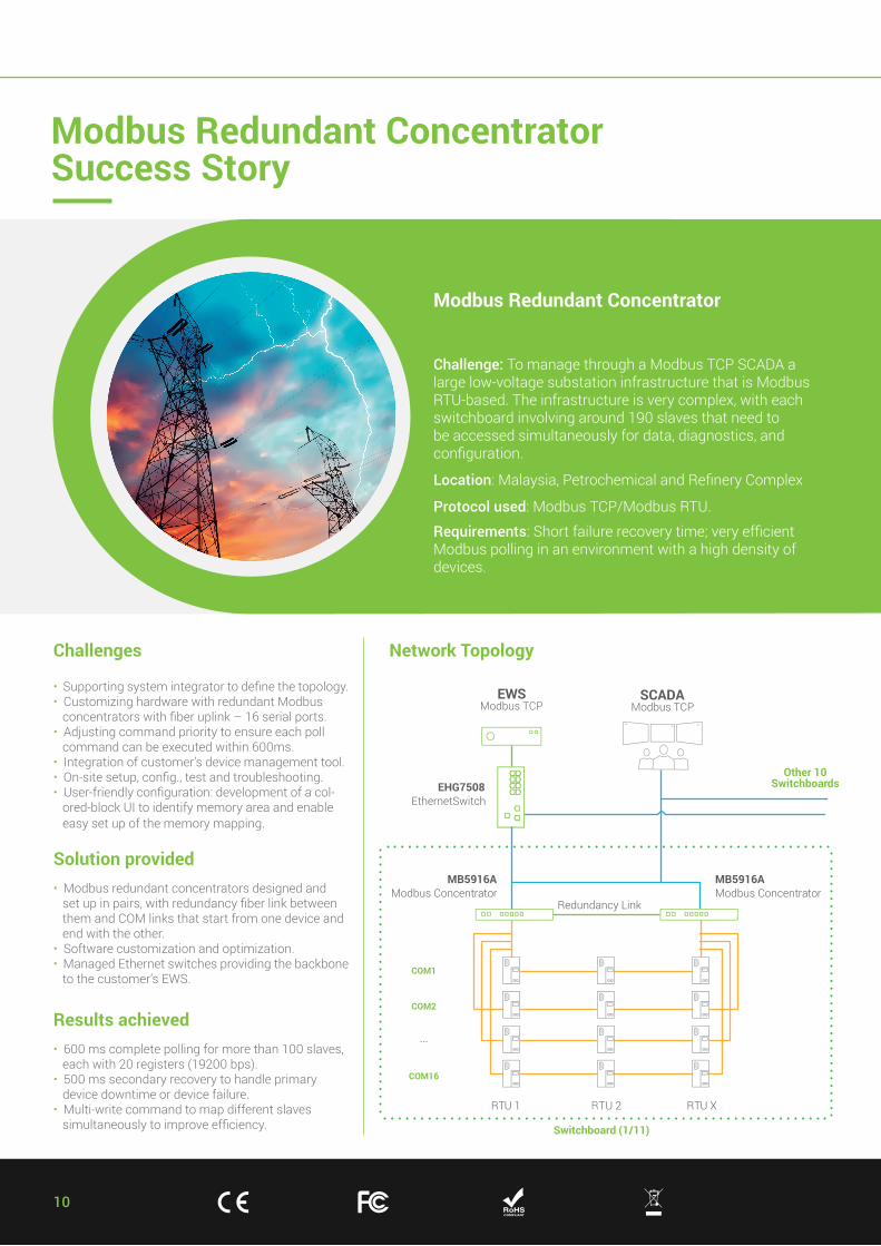
Challenges • Supporting system integrator to define the topology.• Customizing hardware with redundant Modbus concentrators with fiber uplink – 16 serial ports.• Adjusting command priority to ensure each poll command can be executed within 600ms.• Integration of customer’s device management tool.• On-site setup, config., test and troubleshooting.• User-friendly configuration: development of a col- ored-block UI to identify memory area and enable easy set up of the memory mapping.
Solution provided • Modbus redundant concentrators designed and set up in pairs, with redundancy fiber link between them and COM links that start from one device and end with the other.• Software customization and optimization.• Managed Ethernet switches providing the backbone to the customer’s EWS.
Results achieved • 600 ms complete polling for more than 100 slaves, each with 20 registers (19200 bps).• 500 ms secondary recovery to handle primary device downtime or device failure.• Multi-write command to map different slaves simultaneously to improve efficiency.
Network Topology
Modbus Redundant Concentrator
Challenge: To manage through a Modbus TCP SCADA a large low-voltage substation infrastructure that is Modbus RTU-based. The infrastructure is very complex, with each switchboard involving around 190 slaves that need to be accessed simultaneously for data, diagnostics, and configuration.
Location: Malaysia, Petrochemical and Refinery Complex
Protocol used: Modbus TCP/Modbus RTU.
Requirements: Short failure recovery time; very efficient Modbus polling in an environment with a high density of devices.
EWSModbus TCP
SCADAModbus TCP
EHG7508EthernetSwitch
MB5916AModbus Concentrator
MB5916AModbus Concentrator
Redundancy Link
COM1
Switchboard (1/11)
Other 10Switchboards
COM2
COM16
...
RTU 1R TU 2 RTU XR
11+ 886 - 3 - 5508137 + 886 - 3 - 5508131
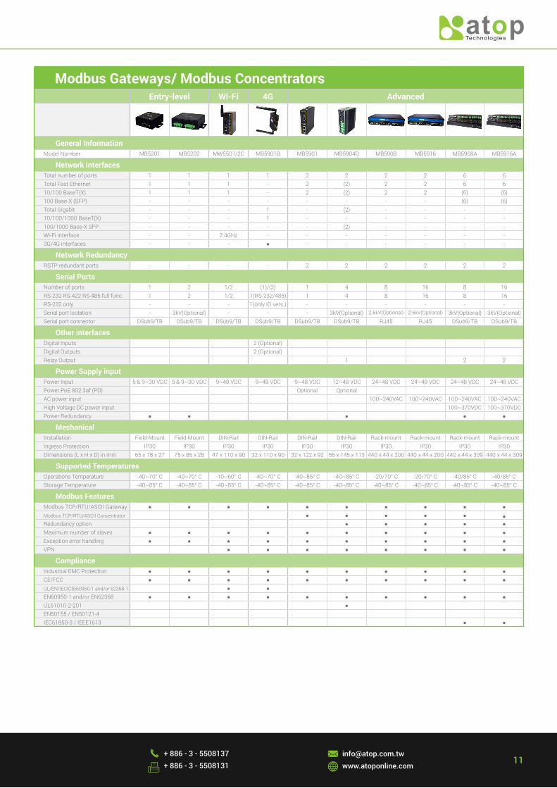
Modbus Gateways/ Modbus ConcentratorsEntry-level Wi-Fi 4G Advanced
General InformationModel Number MB5201 MB5202 MW5501/2C MB5901B MB5901 MB5904D MB5908 MB5916 MB5908A MB5916A
Network InterfacesTotal number of ports 1 1 1 1 2 2 2 2 6 6Total Fast Ethernet 1 1 1 - 2 (2) 2 2 6 610/100 BaseT(X) 1 1 1 - 2 (2) 2 2 (6) (6)100 Base-X (SFP) - - - - - - - - (6) (6)Total Gigabit - - - 1 - (2) - - - -10/100/1000 BaseT(X) - - - 1 - - - - - -100/1000 Base-X SFP - - - - - (2) - - - -Wi-Fi interface - - 2.4GHz - - - - - - -3G/4G interfaces - - - ● - - - - - -
Network RedundancyRSTP redundant ports - - - - 2 2 2 2 2 2
Serial PortsNumber of ports 1 2 1/2 (1)/(2) 1 4 8 16 8 16RS-232 RS-422 RS-485 full func. 1 2 1/2 1(RS-232/485) 1 4 8 16 8 16RS-232 only - - - 1(only IO vers.) - - - - - -Serial port Isolation - 3kV(Optional) - - - 3kV(Optional) 2.5kV(Optional) 2.5kV(Optional) 3kV(Optional) 3kV(Optional)Serial port connector DSub9/TB DSub9/TB DSub9/TB DSub9/TB DSub9/TB DSub9/TB RJ45 RJ45 DSub9/TB DSub9/TB
Other interfacesDigital Inputs 2 (Optional) Digital Outputs 2 (Optional) Relay Output 1 2 2
Power Supply inputPower Input 5 & 9~30 VDC 5 & 9~30 VDC 9~48 VDC 9~48 VDC 9~48 VDC 12~48 VDC 24~48 VDC 24~48 VDC 24~48 VDC 24~48 VDCPower PoE 802.3af (PD) Optional Optional AC power input 100~240VAC 100~240VAC 100~240VAC 100~240VACHigh Voltage DC power input 100~370VDC 100~370VDCPower Redundancy ● ● ● ● ●
MechanicalInstallation Field-Mount Field-Mount DIN-Rail DIN-Rail DIN-Rail DIN-Rail Rack-mount Rack-mount Rack-mount Rack-mountIngress Protection IP30 IP30 IP30 IP30 IP30 IP30 IP30 IP30 IP30 IP30Dimensions (L x H x D) in mm 65 x 78 x 27 75 x 85 x 28 47 x 110 x 90 32 x 110 x 90 32 x 122 x 92 55 x 145 x 113 440 x 44 x 200 440 x 44 x 200 440 x 44 x 309 440 x 44 x 309
Supported TemperaturesOperations Temperature -40~70° C -40~70° C -10~60° C -40~70° C -40~85° C -40~85° C -20/70° C -20/70° C -40/85° C -40/85° C Storage Temperature -40~85° C -40~85° C -40~85° C -40~85° C -40~85° C -40~85° C -40~85° C -40~85° C -40~85° C -40~85° C
Modbus FeaturesModbus TCP/RTU/ASCII Gateway ● ● ● ● ● ● ● ● ● ●Modbus TCP/RTU/ASCII Concentrator ● ● ● ● ● ●Redundancy option ● ● ● ● ●Maximum number of slaves ● ● ● ● ● ● ● ● ● ●Exception error handling ● ● ● ● ● ● ● ● ● ●VPN ● ● ● ● ● ● ● ●
ComplianceIndustrial EMC Protection ● ● ● ● ● ● ● ● ● ●CE/FCC ● ● ● ● ● ● ● ● ● ●UL/EN/IEC(CB)60950-1 and/or 62368-1 ● ● EN60950-1 and/or EN62368 ● ● ● ● ● ● ● ● ● ●UL61010-2-201 ● EN50155 / EN50121-4 IEC61850-3 / IEEE1613 ● ●
12
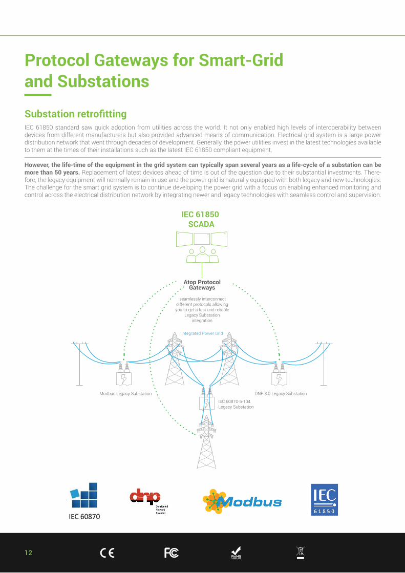
IEC 61850 standard saw quick adoption from utilities across the world. It not only enabled high levels of interoperability between devices from different manufacturers but also provided advanced means of communication. Electrical grid system is a large power distribution network that went through decades of development. Generally, the power utilities invest in the latest technologies available to them at the times of their installations such as the latest IEC 61850 compliant equipment.
However, the life-time of the equipment in the grid system can typically span several years as a life-cycle of a substation can be more than 50 years. Replacement of latest devices ahead of time is out of the question due to their substantial investments. There-fore, the legacy equipment will normally remain in use and the power grid is naturally equipped with both legacy and new technologies. The challenge for the smart grid system is to continue developing the power grid with a focus on enabling enhanced monitoring and control across the electrical distribution network by integrating newer and legacy technologies with seamless control and supervision.
IEC 61850 SCADA
Modbus Legacy Substation DNP 3.0 Legacy Substation
IEC 60870-5-104Legacy Substation
Integrated Power Grid
Atop ProtocolGateways
seamlessly interconnectdifferent protocols allowing you to get a fast and reliable
Legacy Substation integration
Protocol Gateways for Smart-Grid and Substations
Substation retrofitting
13+ 886 - 3 - 5508137 + 886 - 3 - 5508131
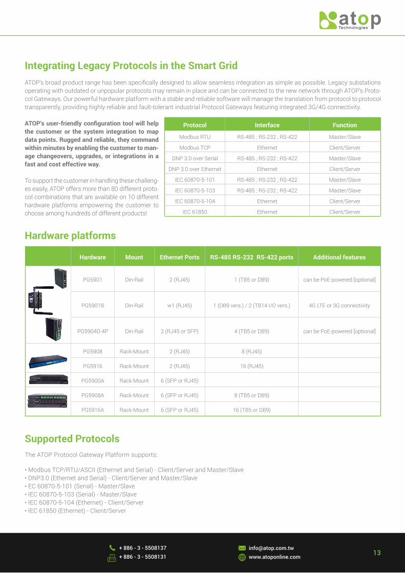
ATOP’s broad product range has been specifically designed to allow seamless integration as simple as possible. Legacy substations operating with outdated or unpopular protocols may remain in place and can be connected to the new network through ATOP’s Proto-col Gateways. Our powerful hardware platform with a stable and reliable software will manage the translation from protocol to protocol transparently, providing highly reliable and fault-tolerant industrial Protocol Gateways featuring integrated 3G/4G connectivity.
ATOP’s user-friendly configuration tool will help the customer or the system integration to map data points. Rugged and reliable, they command within minutes by enabling the customer to man-age changeovers, upgrades, or integrations in a fast and cost effective way.
To support the customer in handling these challeng-es easily, ATOP offers more than 80 different proto-col combinations that are available on 10 different hardware platforms empowering the customer to choose among hundreds of different products!
Integrating Legacy Protocols in the Smart Grid
Protocol Interface Function
Modbus RTU RS-485 ; RS-232 ; RS-422 Master/Slave
Modbus TCP Ethernet Client/Server
DNP 3.0 over Serial RS-485 ; RS-232 ; RS-422 Master/Slave
DNP 3.0 over Ethernet Ethernet Client/Server
IEC 60870-5-101 RS-485 ; RS-232 ; RS-422 Master/Slave
IEC 60870-5-103 RS-485 ; RS-232 ; RS-422 Master/Slave
IEC 60870-5-104 Ethernet Client/Server
IEC 61850 Ethernet Client/Server
Hardware Mount Ethernet Ports RS-485 RS-232 RS-422 ports Additional features
PG5901 Din-Rail 2 (RJ45) 1 (TB5 or DB9) can be PoE-powered [optional]
PG5901B Din-Rail w1 (RJ45) 1 (DB9 vers.) / 2 (TB14 I/O vers.) 4G LTE or 3G connectivity
PG5904D-4P Din-Rail 2 (RJ45 or SFP) 4 (TB5 or DB9) can be PoE-powered [optional]
PG5908 Rack-Mount 2 (RJ45) 8 (RJ45)
PG5916 Rack-Mount 2 (RJ45) 16 (RJ45)
PG5900A Rack-Mount 6 (SFP or RJ45)
PG5908A Rack-Mount 6 (SFP or RJ45) 8 (TB5 or DB9)
PG5916A Rack-Mount 6 (SFP or RJ45) 16 (TB5 or DB9)
Hardware platforms
Supported ProtocolsThe ATOP Protocol Gateway Platform supports:
• Modbus TCP/RTU/ASCII (Ethernet and Serial) - Client/Server and Master/Slave• DNP3.0 (Ethernet and Serial) - Client/Server and Master/Slave• EC 60870-5-101 (Serial) - Master/Slave• IEC 60870-5-103 (Serial) - Master/Slave• IEC 60870-5-104 (Ethernet) - Client/Server• IEC 61850 (Ethernet) - Client/Server
14
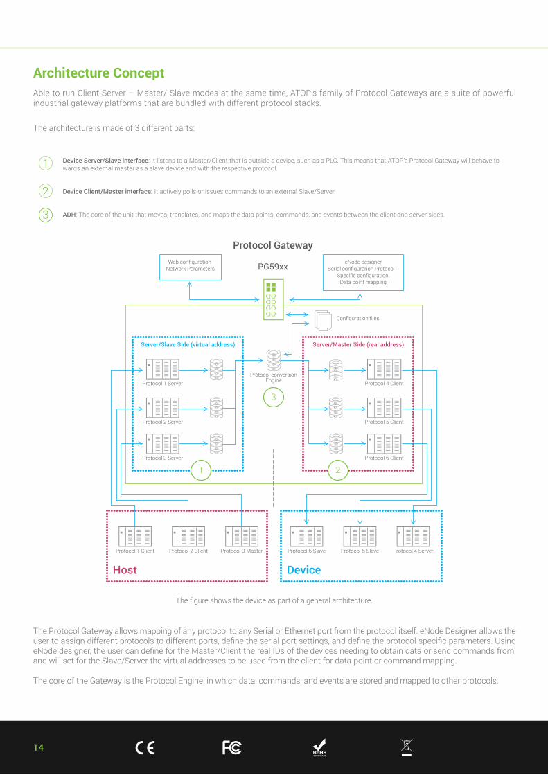
Device Server/Slave interface: It listens to a Master/Client that is outside a device, such as a PLC. This means that ATOP’s Protocol Gateway will behave to-wards an external master as a slave device and with the respective protocol.
Device Client/Master interface: It actively polls or issues commands to an external Slave/Server.
ADH: The core of the unit that moves, translates, and maps the data points, commands, and events between the client and server sides.
The figure shows the device as part of a general architecture.
The architecture is made of 3 different parts:
1
2
3
The Protocol Gateway allows mapping of any protocol to any Serial or Ethernet port from the protocol itself. eNode Designer allows the user to assign different protocols to different ports, define the serial port settings, and define the protocol-specific parameters. Using eNode designer, the user can define for the Master/Client the real IDs of the devices needing to obtain data or send commands from, and will set for the Slave/Server the virtual addresses to be used from the client for data-point or command mapping.
The core of the Gateway is the Protocol Engine, in which data, commands, and events are stored and mapped to other protocols.
Architecture ConceptAble to run Client-Server – Master/ Slave modes at the same time, ATOP’s family of Protocol Gateways are a suite of powerful industrial gateway platforms that are bundled with different protocol stacks.
15+ 886 - 3 - 5508137 + 886 - 3 - 5508131
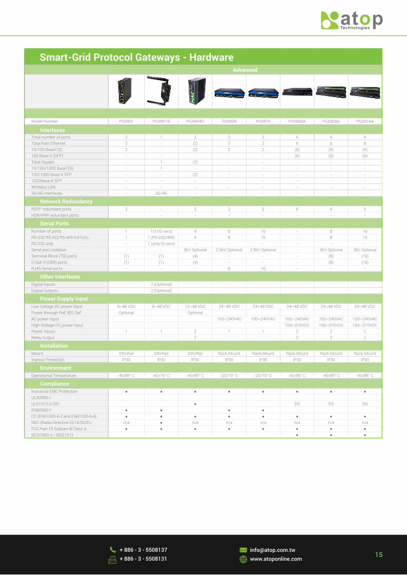
Smart-Grid Protocol Gateways - HardwareAdvanced
Model Number PG5901 PG5901B PG5904D PG5908 PG5916 PG5900A PG5908A PG5916A
InterfacesTotal number of ports 2 1 2 2 2 6 6 6Total Fast Ethernet 2 - (2) 2 2 6 6 610/100 BaseT(X) 2 - (2) 2 2 (6) (6) (6)100 Base-X (SFP) - - - - - (6) (6) (6)Total Gigabit - 1 (2) - - - - -10/100/1000 BaseT(X) - 1 - - - - - -100/1000 Base-X SFP - - (2) - - - - -1000Base-X SFP - - - - - - - -Wireless LAN - - - - - - - -3G/4G interfaces - 3G/4G - - - - - -
Network RedundancyRSTP redundant ports 2 - 2 2 2 6 6 6HSR/PRP redundant ports - - - - - - - -
Serial PortsNumber of ports 1 1/2 (IO vers) 4 8 16 - 8 16RS-232 RS-422 RS-485 full func. 1 1 (RS-232/485) 4 8 16 - 8 16RS-232 only - 1 (only IO vers) - - - - - -Serial port Isolation - - 3kV Optional 2.5kV Optional 2.5kV Optional - 3kV Optional 3kV OptionalTerminal Block (TB) ports (1) (1) (4) - - - (8) (16)D-Sub 9 (DB9) ports (1) (1) (4) - - - (8) (16)RJ45 Serial ports - - - 8 16 - - -
Other InterfacesDigital Inputs 2 (Optional) Digital Outputs 2 (Optional)
Power Supply inputLow Voltage DC power Input 9~48 VDC 9~48 VDC 12~48 VDC 24~48 VDC 24~48 VDC 24~48 VDC 24~48 VDC 24~48 VDCPower through PoE 802.3af Optional Optional AC power input 100~240VAC 100~240VAC 100~240VAC 100~240VAC 100~240VACHigh Voltage DC power input 100~370VDC 100~370VDC 100~370VDCPower Inputs 1 1 2 1 1 2 2 2Relay Output 2 2 2 2
Installation Mount DIN-Rail DIN-Rail DIN-Rail Rack-Mount Rack-Mount Rack-Mount Rack-Mount Rack-MountIngress Protection IP30 IP30 IP30 IP30 IP30 IP30 IP30 IP30
EnvironmentOperational Temperature -40/85° C -40/75° C -40/85° C -20/70° C -20/70° C -40/85° C -40/85° C -40/85° C
ComplianceIndustrial EMC Protection ● ● ● ● ● ● ● ●UL60950-1 UL61010-2-201 ● EN EN ENEN60950-1 ● ● ● ● CE (EN61000-6-2 and EN61000-6-4) ● ● ● ● ● ● ● ●RED (Radio Directive 2014/53/EU n/a ● n/a n/a n/a n/a n/a n/aFCC Part 15 Subpart B Class A ● ● ● ● ● ● ● ●IEC61850-3 / IEEE1613 ● ● ●
16
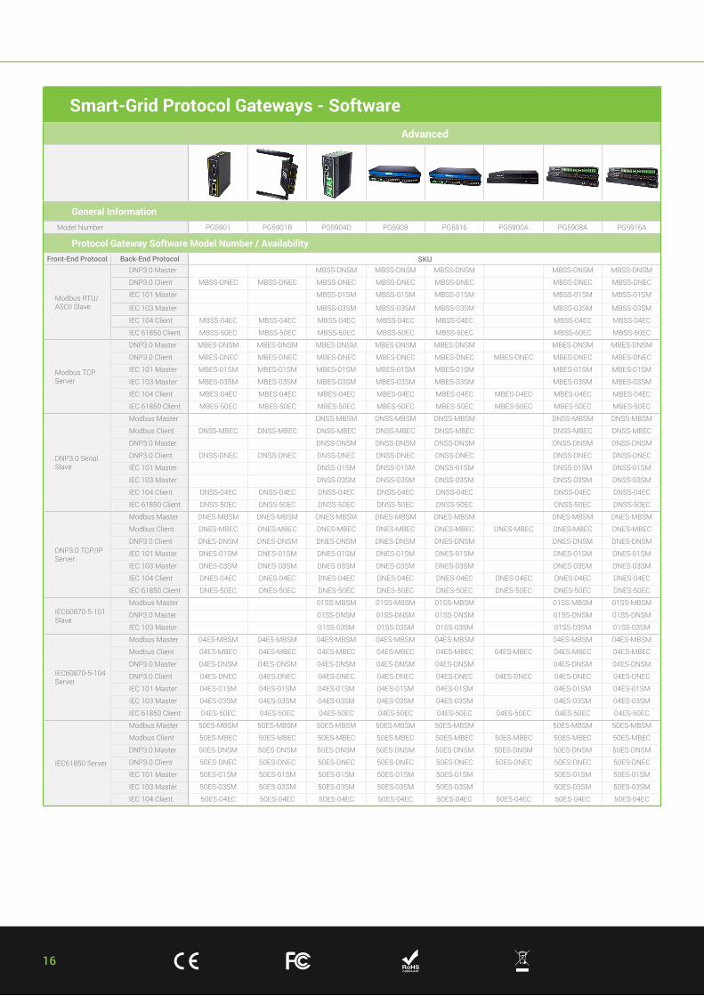
Smart-Grid Protocol Gateways - SoftwareAdvanced
General InformationModel Number PG5901 PG5901B PG5904D PG5908 PG5916 PG5900A PG5908A PG5916A
Protocol Gateway Software Model Number / AvailabilityFront-End Protocol Back-End Protocol SKU
Modbus RTU/ASCII Slave
DNP3.0 Master MBSS-DNSM MBSS-DNSM MBSS-DNSM MBSS-DNSM MBSS-DNSM
DNP3.0 Client MBSS-DNEC MBSS-DNEC MBSS-DNEC MBSS-DNEC MBSS-DNEC MBSS-DNEC MBSS-DNEC
IEC 101 Master MBSS-01SM MBSS-01SM MBSS-01SM MBSS-01SM MBSS-01SM
IEC 103 Master MBSS-03SM MBSS-03SM MBSS-03SM MBSS-03SM MBSS-03SM
IEC 104 Client MBSS-04EC MBSS-04EC MBSS-04EC MBSS-04EC MBSS-04EC MBSS-04EC MBSS-04EC
IEC 61850 Client MBSS-50EC MBSS-50EC MBSS-50EC MBSS-50EC MBSS-50EC MBSS-50EC MBSS-50EC
Modbus TCP Server
DNP3.0 Master MBES-DNSM MBES-DNSM MBES-DNSM MBES-DNSM MBES-DNSM MBES-DNSM MBES-DNSM
DNP3.0 Client MBES-DNEC MBES-DNEC MBES-DNEC MBES-DNEC MBES-DNEC MBES-DNEC MBES-DNEC MBES-DNEC
IEC 101 Master MBES-01SM MBES-01SM MBES-01SM MBES-01SM MBES-01SM MBES-01SM MBES-01SM
IEC 103 Master MBES-03SM MBES-03SM MBES-03SM MBES-03SM MBES-03SM MBES-03SM MBES-03SM
IEC 104 Client MBES-04EC MBES-04EC MBES-04EC MBES-04EC MBES-04EC MBES-04EC MBES-04EC MBES-04EC
IEC 61850 Client MBES-50EC MBES-50EC MBES-50EC MBES-50EC MBES-50EC MBES-50EC MBES-50EC MBES-50EC
DNP3.0 Serial Slave
Modbus Master DNSS-MBSM DNSS-MBSM DNSS-MBSM DNSS-MBSM DNSS-MBSM
Modbus Client DNSS-MBEC DNSS-MBEC DNSS-MBEC DNSS-MBEC DNSS-MBEC DNSS-MBEC DNSS-MBEC
DNP3.0 Master DNSS-DNSM DNSS-DNSM DNSS-DNSM DNSS-DNSM DNSS-DNSM
DNP3.0 Client DNSS-DNEC DNSS-DNEC DNSS-DNEC DNSS-DNEC DNSS-DNEC DNSS-DNEC DNSS-DNEC
IEC 101 Master DNSS-01SM DNSS-01SM DNSS-01SM DNSS-01SM DNSS-01SM
IEC 103 Master DNSS-03SM DNSS-03SM DNSS-03SM DNSS-03SM DNSS-03SM
IEC 104 Client DNSS-04EC DNSS-04EC DNSS-04EC DNSS-04EC DNSS-04EC DNSS-04EC DNSS-04EC
IEC 61850 Client DNSS-50EC DNSS-50EC DNSS-50EC DNSS-50EC DNSS-50EC DNSS-50EC DNSS-50EC
DNP3.0 TCP/IP Server
Modbus Master DNES-MBSM DNES-MBSM DNES-MBSM DNES-MBSM DNES-MBSM DNES-MBSM DNES-MBSM
Modbus Client DNES-MBEC DNES-MBEC DNES-MBEC DNES-MBEC DNES-MBEC DNES-MBEC DNES-MBEC DNES-MBEC
DNP3.0 Client DNES-DNSM DNES-DNSM DNES-DNSM DNES-DNSM DNES-DNSM DNES-DNSM DNES-DNSM
IEC 101 Master DNES-01SM DNES-01SM DNES-01SM DNES-01SM DNES-01SM DNES-01SM DNES-01SM
IEC 103 Master DNES-03SM DNES-03SM DNES-03SM DNES-03SM DNES-03SM DNES-03SM DNES-03SM
IEC 104 Client DNES-04EC DNES-04EC DNES-04EC DNES-04EC DNES-04EC DNES-04EC DNES-04EC DNES-04EC
IEC 61850 Client DNES-50EC DNES-50EC DNES-50EC DNES-50EC DNES-50EC DNES-50EC DNES-50EC DNES-50EC
IEC60870-5-101 Slave
Modbus Master 01SS-MBSM 01SS-MBSM 01SS-MBSM 01SS-MBSM 01SS-MBSM
DNP3.0 Master 01SS-DNSM 01SS-DNSM 01SS-DNSM 01SS-DNSM 01SS-DNSM
IEC 103 Master 01SS-03SM 01SS-03SM 01SS-03SM 01SS-03SM 01SS-03SM
IEC60870-5-104 Server
Modbus Master 04ES-MBSM 04ES-MBSM 04ES-MBSM 04ES-MBSM 04ES-MBSM 04ES-MBSM 04ES-MBSM
Modbus Client 04ES-MBEC 04ES-MBEC 04ES-MBEC 04ES-MBEC 04ES-MBEC 04ES-MBEC 04ES-MBEC 04ES-MBEC
DNP3.0 Master 04ES-DNSM 04ES-DNSM 04ES-DNSM 04ES-DNSM 04ES-DNSM 04ES-DNSM 04ES-DNSM
DNP3.0 Client 04ES-DNEC 04ES-DNEC 04ES-DNEC 04ES-DNEC 04ES-DNEC 04ES-DNEC 04ES-DNEC 04ES-DNEC
IEC 101 Master 04ES-01SM 04ES-01SM 04ES-01SM 04ES-01SM 04ES-01SM 04ES-01SM 04ES-01SM
IEC 103 Master 04ES-03SM 04ES-03SM 04ES-03SM 04ES-03SM 04ES-03SM 04ES-03SM 04ES-03SM
IEC 61850 Client 04ES-50EC 04ES-50EC 04ES-50EC 04ES-50EC 04ES-50EC 04ES-50EC 04ES-50EC 04ES-50EC
IEC61850 Server
Modbus Master 50ES-MBSM 50ES-MBSM 50ES-MBSM 50ES-MBSM 50ES-MBSM 50ES-MBSM 50ES-MBSM
Modbus Client 50ES-MBEC 50ES-MBEC 50ES-MBEC 50ES-MBEC 50ES-MBEC 50ES-MBEC 50ES-MBEC 50ES-MBEC
DNP3.0 Master 50ES-DNSM 50ES-DNSM 50ES-DNSM 50ES-DNSM 50ES-DNSM 50ES-DNSM 50ES-DNSM 50ES-DNSM
DNP3.0 Client 50ES-DNEC 50ES-DNEC 50ES-DNEC 50ES-DNEC 50ES-DNEC 50ES-DNEC 50ES-DNEC 50ES-DNEC
IEC 101 Master 50ES-01SM 50ES-01SM 50ES-01SM 50ES-01SM 50ES-01SM 50ES-01SM 50ES-01SM
IEC 103 Master 50ES-03SM 50ES-03SM 50ES-03SM 50ES-03SM 50ES-03SM 50ES-03SM 50ES-03SM
IEC 104 Client 50ES-04EC 50ES-04EC 50ES-04EC 50ES-04EC 50ES-04EC 50ES-04EC 50ES-04EC 50ES-04EC
17+ 886 - 3 - 5508137 + 886 - 3 - 5508131
Wireless Routers
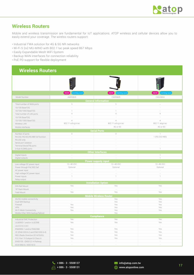
Model Number AWR5805 CWR5805 CWG5804
General Information Total number of WAN ports 1 1 -
10/100 BaseT(X) - - -
10/100/1000 BaseT(X) 1 1 -Total number of LAN ports 4 4 4
10/100 BaseT(X) - - -
10/100/1000 BaseT(X) 4 4 4Wireless LAN 802.11 a/b/g/n/ac 802.11 a/b/g/n/ac 802.11 abgn/ac
Mobile interfaces - 4G or 5G 4G or 5G
Serial PortsNumber of ports 0 0 1RS-232, RS-422,RS-485 full function - - 1 (RS-232/485)RS-232 only - - -Serial port isolation - - -Terminal block(TB) ports - - -D-Sub 9 (DB9) ports - - 1
Other InterfacesDigital Inputs - - 1Digital outputs - - 1
Power suppoly inputLow voltage DC power input 12~48 VDC 12~48 VDC 12~48 VDCPower through PoE 802.3af Optional Optional OptionalAC power input - - -High voltage DC power input - - -Power inputs 1 1 1Relay output - - -
Installation OptionDIN-Rail Mount Yes Yes Yes
19" Rack Mount - - -Field Mount Yes Yes Yes
Mobile Wireless Router4G/5G mobile connectivity - Yes YesDual-SIM Backup - Yes YesFirewall Yes Yes YesVPN Yes Yes YesWi-Fi Mesh Connectivity Yes Yes YesMobile Ether WAN backup/failover - Yes -
ComplianceIndustrial EMC Protection Yes Yes Yes
UL60950-1 and/or UL62368 Yes Yes Yes
UL61010-2-201 - - -
EN60950-1 and/or EN62368 Yes Yes Yes
CE (EN61000-6-2 and EN61000-6-4) Yes Yes Yes
RED (Radio Directive 2014/53/EU Yes Yes Yes
FCC Part 15 Subpart B Class A Yes Yes Yes
EN50155 - EN50121-4 Railway - - -
IEC61850-3 / IEEE1613 - - -
Wireless RoutersMobile and wireless transmission are fundamental for IoT applications. ATOP wireless and cellular devices allow you to easily extend your coverage. The wirelss routers support:
• Industrial FWA solution for 4G & 5G NR networks • Wi-Fi 5 2x2 MU-MINO with 802.11ac peak speed 867 Mbps• Easily Expandable Mesh WiFi System • Backup WAN interfaces for connection reliability• PoE PD support for flexible deployment
NEW! NEW! NEW!
18+ 886 - 3 - 5508137 + 886 - 3 - 5508131
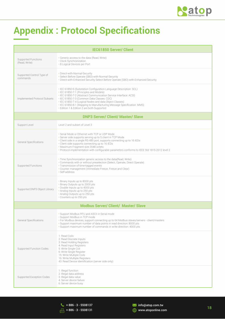
IEC61850 Server/ Client
Supported Functions(Read, Write)
• Generic access to the data (Read, Write)• Clock Synchronization• 8 Logical Devices per Port
Supported Control Type of commands
• Direct-with-Normal-Security• Select Before Operate (SBO)-with-Normal-Security• Direct-with-Enhanced Security Select Before Operate (SBO)-with-Enhanced-Security
Implemented Protocol Subsets
• IEC 61850-6 (Substation Configuration Language Description: SCL)• IEC 61850-7-1 (Principles and Models)• IEC 61850-7-2 (Abstract Communication Service Interface: ACSI)• IEC 61850-7-3 (Common Data Classes: CDC)• IEC 61850-7-4 (Logical Nodes and data Object Classes)• IEC 61850-8-1 (Mapping to Manufacturing Message Specification: MMS)• Edition 1 & Edition 2 are both Supported
DNP3 Server/ Client/ Master/ Slave
Support Level Level 2 and subset of Level 3
General Specifications
• Serial Mode or Ethernet with TCP or UDP Mode• Server side supports serving up to 5 client in TCP Mode• Client side in a single RS-485 port, supports connecting up to 16 IEDs• Client side supports connecting up to 16 IEDs• Maximum Fragment size 2048 octets • Protocol implementation with configurable parameters conforms to IEEE Std 1815-2012 level 2
Supported Functions
• Time Synchronization generic access to the data(Read, Write)• Commands with or without preselection (Select, Operate, Direct Operate)• Transmission of time-tagged events • Counter management (Immediate Freeze, Freeze and Clear)• Self-address
Supported DNP3 Object Library
• Binary Inputs up to 8000 pts• Binary Outputs up to 2000 pts• Double Inputs up to 4000 pts• Analog Inputs up to 250 pts• Analog Outputs up to 250 pts• Counters up to 250 pts
Modbus Server/ Client/ Master/ Slave
General Specifications
• Support Modbus RTU and ASCII in Serial mode• Support Modbus in TCP mode• For Modbus devices, support connecting up to 64 Modbus slaves/servers - client/masters• Support maximum number of data points in read direction: 8000 pts• Support maximum number of commands in write direction: 4000 pts
Supported Function Codes
1: Read Coils2: Read Discrete Inputs3: Read Holding Registers4: Read Input Registers5: Write Single Coil6: Write Single Register15: Write Multiple Coils16: Write Multiple Registers43: Read Device Identification (server side only)
Supported Exception Codes
1: Illegal function2: Illegal data address3: Illegal data value4: Server device failure6: Server device busy
Appendix : Protocol Specifications

19
IEC 60870-5-101 Master/ Slave
General Specifications
• Protocol implementation with configurable parameters conforms to the IEC 60870-5-101 edition 2 specification • Process Information in Monitor and Control Direction• Balanced and Unbalanced Modes• CP24Time2a or CP56Time2a timestamp for monitor direction report
Supported Functions
• Station Initialization• Interrogation• Read Procedure• Cyclic Data and Spontaneous Transmission (Slave Side only)• Clock Synchronization• Transmission of Integrated Totals• Direct and SBO command
Supported Data Types
• Monitors Points: Each supports up to 1000 pts: Single Point, Double Point, Step Position, Bit String, Measured with Normalized Value, Measured with Scaled Value, Measured Short Floating Point Value, Integrated Totals
• Control Points: Each supports up to 500 pts: Single Command, Double Command, Regulating Step Command, Set Point Command with Normalized Value, Set Point Command with Scaled Value, Set Point Command Short Floating Point, Bit string
IEC 60870-5-103 Master
General Specifications
• Protocol implementation with configurable parameters conforms to the IEC 60870-5-103:1997• Master supports connecting up to 16 IEDs• Process Information in Monitor and Control Direction• Unbalanced Modes
Supported Functions
• Station Initialization, Supports reset FCB and CU• General Interrogation• Clock Synchronization• Command Transmission• Test Mode• Blocking of Monitor Direction
Supported Data Types
• Monitor direction: * Status indications in monitor direction: from <16> to <30> * Supervision indications in monitor direction: <32>, <33>, from <35> to< 39>, <46>, <47> * Earth fault indications in monitor direction: from <48> to <52> * Fault indications in monitor direction: from <64> to <93> * Auto-reclosure indications in monitor direction: from <128> to <130> * Measurands in monitor direction: from <144> to <148>• Control direction: * General commands in control direction: from <16> to <19>, from <23> to <26>
IEC 60870-5-104 Server/ Client
General Specifications
• Server side supports serving up to 5 client• Client side supports connecting up to 10 IEDs• Protocol implementation with configurable parameters conforms to the IEC 60870-5-104 specification edition 2• Process Information in Monitor and Control Direction• CP56Time2a timestamp for Control Commands
Supported Functions
• Station Initialization• Interrogation• Read Procedure• Cyclic Data and Spontaneous Transmission (Slave Side only)• Clock Synchronization• Transmission of Integrated Totals• Direct and SBO command
Supported Data Types
• Monitors Points: Each supports maximum 1000 pts: Single Point, Double Point, Step Position, Bit String, Measured with Normalized Value, Measured with Scaled Value, Measured Short Floating Points Value, Integrated Totals.
• Control Points: Each supports maximum 500 pts: Single Command, Double Command, Regulating Step Command, Set Point Command with Normalized Value, Set Point Command with Scaled Value, Set Point Command Short Floating Point, Bitstring.
• Event Logging (Server Side only) Universal Event Buffer up to 20,000 Events
IEC61850 Server/ Client
Supported Functions(Read, Write)
• Generic access to the data (Read, Write)• Clock Synchronization• 8 Logical Devices per Port
Supported Control Type of commands
• Direct-with-Normal-Security• Select Before Operate (SBO)-with-Normal-Security• Direct-with-Enhanced Security Select Before Operate (SBO)-with-Enhanced-Security
Implemented Protocol Subsets
• IEC 61850-6 (Substation Configuration Language Description: SCL)• IEC 61850-7-1 (Principles and Models)• IEC 61850-7-2 (Abstract Communication Service Interface: ACSI)• IEC 61850-7-3 (Common Data Classes: CDC)• IEC 61850-7-4 (Logical Nodes and data Object Classes)• IEC 61850-8-1 (Mapping to Manufacturing Message Specification: MMS)• Edition 1 & Edition 2 are both Supported
DNP3 Server/ Client/ Master/ Slave
Support Level Level 2 and subset of Level 3
General Specifications
• Serial Mode or Ethernet with TCP or UDP Mode• Server side supports serving up to 5 client in TCP Mode• Client side in a single RS-485 port, supports connecting up to 16 IEDs• Client side supports connecting up to 16 IEDs• Maximum Fragment size 2048 octets • Protocol implementation with configurable parameters conforms to IEEE Std 1815-2012 level 2
Supported Functions
• Time Synchronization generic access to the data(Read, Write)• Commands with or without preselection (Select, Operate, Direct Operate)• Transmission of time-tagged events • Counter management (Immediate Freeze, Freeze and Clear)• Self-address
Supported DNP3 Object Library
• Binary Inputs up to 8000 pts• Binary Outputs up to 2000 pts• Double Inputs up to 4000 pts• Analog Inputs up to 250 pts• Analog Outputs up to 250 pts• Counters up to 250 pts
Modbus Server/ Client/ Master/ Slave
General Specifications
• Support Modbus RTU and ASCII in Serial mode• Support Modbus in TCP mode• For Modbus devices, support connecting up to 64 Modbus slaves/servers - client/masters• Support maximum number of data points in read direction: 8000 pts• Support maximum number of commands in write direction: 4000 pts
Supported Function Codes
1: Read Coils2: Read Discrete Inputs3: Read Holding Registers4: Read Input Registers5: Write Single Coil6: Write Single Register15: Write Multiple Coils16: Write Multiple Registers43: Read Device Identification (server side only)
Supported Exception Codes
1: Illegal function2: Illegal data address3: Illegal data value4: Server device failure6: Server device busy

TAIWAN HEADQUARTERS2F, No. 146, Sec. 1, Dongxing Rd., Zhubei City, Hsinchu County, TaiwanTel: +886-3-550-8137 Fax: +886-3-550-8131E-mail: [email protected] www.atoponline.com
Atop Technologies, Inc.