concentrated solar power generation by zhilei jin a · pdf fileconcentrated solar power...
TRANSCRIPT

Concentrated Solar Power Generation
by
Zhilei Jin
A Thesis Presented in Partial Fulfillment
of the Requirements for the Degree
Master of Science
Approved November 2013 by the
Graduate Supervisory Committee:
Yu Hui, Chair
Raja Ayyanar
Armando Rodriguez
ARIZONA STATE UNIVERSITY
December 2013

i
ABSTRACT
Solar power generation is the most promising technology to transfer energy
consumption reliance from fossil fuel to renewable sources. Concentrated solar power
generation is a method to concentrate the sunlight from a bigger area to a smaller area.
The collected sunlight is converted more efficiently through two types of technologies:
concentrated solar photovoltaics (CSPV) and concentrated solar thermal power (CSTP)
generation.
In this thesis, these two technologies were evaluated in terms of system
construction, performance characteristics, design considerations, cost benefit analysis and
their field experience. The two concentrated solar power generation systems were
implemented with similar solar concentrators and solar tracking systems but with
different energy collecting and conversion components: the CSPV system uses high
efficiency multi-junction solar cell modules, while the CSTP system uses a boiler -
turbine-generator setup. The performances are calibrated via the experiments and
evaluation analysis.

ii
ACKNOWLEDGMENTS
I would like to express my sincere thanks to my beloved family and friends,
especially my advisor, Professor Joseph Yu Hui, for his teaching and help throughout my
time in the graduate program at Arizona State University.
In addition, I would like to thank Professor Armando Rodriguez and Raja
Ayyanar for being a part of my graduate committee.
Last but not the least, my sincere thanks to my auntie Jenny Zheng and her
husband Will Cai for their great support and help throughout my study in United States.

iii
TABLE OF CONTENTS
Page
LIST OF FIGURES ......................................................................................................... v
CHAPTER
1 INTRODUCTION .................. ............................................................................. 1
1.1 Renewable Solar Energy Resource Source Status ........................... 1
1.2 U.S. Solar Power Development ...................................................... 3
1.3 Solar Power Generation Technologies ............................................ 5
1.4 Concentrated Photovoltaics ............................................................ 7
1.5 Concentrated Solar Thermal Power Generation .............................. 9
1.6 Implemented CSPV and CSTP Systems ....................................... 12
1.7 Thesis Layout .............................................................................. 13
2 COCENTRATED SOLAR PHOTOVOLTAICS SYSTEM ............................... 15
2.1 CSPV System Components .......................................................... 15
2.2 CSPV Optics Design .................................................................... 17
2.3 Economic Analysis of CSPV........................................................ 29
3 A CSPV SYSTEM CALLED THE SOLAR UMBRELLA .................. ............... 33
3.1 Concentraed Photovoltaic Generation Unit ................................... 33
3.2 Solar Umbrella Concentrator Designs ........................................... 35
3.3 CSPV Tracking Systems .............................................................. 45
3.4 Solar Tracking Systems Review ................................................... 47
3.5 Solar Umbrella Dual Axis Tracking ............................................. 51

iv
CHAPTER Page
4 A CONCENTRATED SOLAR THERMAL POWER SYSTEM ....................... 56
4.1 The CSTP System Components.................................................... 56
4.2 CSTP System Modeling ............................................................... 57
4.3 Anaylsis of Micro Disk Turbine ................................................... 62
4. 4 Disk Micro Turbine Prototyping and Test .................................... 65
5 CONCLUSION ................... ............................................................................. 71
REFERENCES....... ....................................................................................................... 73

v
LIST OF FIGURES
Figure Page
1. Fig 1.1 Worldwide Direct Normal Irradiation Distribution Map ................. 3
2. Fig 1.2 Solar Radiation Spectrum ............................................................. 6
3. Fig 1.3 Schematic of a Triple Junction Solar Cell ...................................... 7
4. Fig 1.4 A Solar Trough System .............................................................. 10
5. Fig 1.5 A Solar Tower System ............................................................... 11
6. Fig 1.6 A Dish-Heat Engine System ....................................................... 11
7. Fig 2.1 Solar Cells Module I-V Characteristics ........................................ 16
8. Fig 2.2 Solar Cells Efficiency versus Concentration Ratio ........................ 17
9. Fig 2.3 Principle of Concentrating Sunlight ............................................ 18
10. Fig 2.4 Refractive Concentrator .............................................................. 19
11. Fig 2.5 Concept of a CSPV Concentrator Module ................................... 20
12. Fig 2.6 Concept of of a Concentrator ...................................................... 21
13. Fig 2.7 Geometry of a CPC ..................................................................... 22
14. Fig 2.8 Trajactories of the Edge Rays inside a CPC ................................ 22
15. Fig 2.9 Two-stage Concentrator using Reflective Mirros ......................... 23
16. Fig 2.10 Cassegrain Optic Concentrator .................................................. 23
17. Fig 2.11 Cassegrain Telescope Principle .................................................. 24
18. Fig 2.12 Concentror Design of Solfocus ................................................. 25
19. Fig 2.13 The CSPV Panel of Solfocus .................................................... 25
20. Fig 2.14 Concept of a Light-guiding Concentrator ................................... 26
21. Fig 2.15 Light Guide Optical Concentraor Module ................................... 27

vi
Figure Page
22. Fig 2.16 Trajactories of Lights Travelling in the Concentrator ................. 27
23. Fig 2.17 Principle of a Holographic Film Concentrator ........................... 28
24. Fig 2.18 Schematic of a Micro-Optic Slab Concentrator .......................... 29
25. Fig 2.19 CSPV Cell,Module & System Efficiency Roadmap .................... 32
26. Fig 3.1 The Concept of Unfolded and Folded SU .................................... 35
27. Fig 3.2 Parabola Dish Geometry ............................................................. 36
28. Fig 3.3 Two-stage Concentrator Concept ................................................ 37
29. Fig 3.4 Concept Diagram of the Concentrator ......................................... 37
30. Fig 3.5 Efficiency versus Concentration Ratio for Multijunction cells ...... 38
31. Fig 3.6 Schematic of Concentrator Cones Design .................................... 39
32. Fig 3.7 Geometries of the Cones ............................................................. 40
33. Fig 3.8 Schematic of Newtonian Telescope ............................................. 40
34. Fig 3.9 Geometry of Three Stages of Solar Concentration ........................ 41
35. Fig 3.10 Two Co-focal Parabolas ........................................................... 42
36. Fig 3.11 The Folded 1Meter SU Prototype .............................................. 44
37. Fig 3.12 Unfoled 1Meter SU Prototype .................................................. 44
38. Fig 3.13 Folding Layers Geometry .......................................................... 45
39. Fig 3.14 Principle of Intensity of Light on PV Cell .................................. 46
40. Fig 3.15 Output max Power versus Angle Degrees off Axis .................... 46
41. Fig 3.16 Horizontal Single Axis Tracker ................................................. 48
42. Fig 3.17 Vertical Single Axis Tracker ..................................................... 48
43. Fig 3.18 Tilted Single Axis Tracker ......................................................... 49

vii
Figure Page
44. Fig 3.19 Tip-Tilt Dual Axis Tracker ........................................................ 50
45. Fig 3.20 Azimuth-Altitude Dual Axis Tracker ........................................ 51
46. Fig 3.21 Dual Axis Trackign Test Platform ............................................. 53
47. Fig 3.22 Solar Tracking Control Blocks .................................................. 54
48. Fig 3.23 Diagram of the SU Positioning System ..................................... 55
49. Fig 4.1 The Designed CSTP Structure .................................................... 56
50. Fig 4.2 Turbine Function Principle Diagram ........................................... 59
51. Fig 4.3 Sprial Shape Micro Tunnel ......................................................... 61
52. Fig 4.4 Rankine Cycle Stages ................................................................. 63
53. Fig 4.5 Turbine Concepts CAD Design ................................................... 66
54. Fig 4.6 The Disk Turbine Evolved Designs ............................................. 66
55. Fig 4.7 Disk Turbine Test Setup .............................................................. 67
56. Fig 4.8 Rotation Speeds versus Varied Gas Flow Rate ............................. 68
57. Fig 4.9 Voltages versus Varied Gas Flow Rate ........................................ 68
55. Fig 4.10 Power versus Varied Gas Flow Rate .......................................... 69

1
CHAPTER 1
INTRODUCTION
1.1 Renewable Solar Energy Resource Status
The global energy challenge is a critical issue facing the world with the depleting
of coal, oil and natural gas and the increasing energy consumption. The world should rely
more on green renewable energy sources other than the conventional fossil fuels.
Ongoing research tries to find more efficient methods of using renewable energy forms
such as sunlight, wind, biomass, tides and geothermal heat.
In general, there are factors to consider for selecting the best energy solution for a
specific application, such as the location, the ease of installation, technology reliability,
energy output capacity and cost [1]. For example, geothermal heat is location dependent,
while wind energy is relatively low cost but unreliable due to intermittent wind condition.
Also wind power needs regular mechanical maintenances.
Solar energy is the most abundant renewable energy source which is readily
available anywhere the sun shines [2]. Solar energy is easy to collect and use with
relatively lower overall cost comparing with the other renewable energy sources. Even
though solar energy has benefits of being nonpolluting and minimal environmental
impact, it does have limitations such as intermittent energy supply as the sun shines only
at daytime, and energy conversion efficiency can be low. Sunlight is also a quite diluted
power resource which requires a big collecting area to get a sizeable amount of energy
[3].
With the advancement of the modern technologies, there are more effective
solutions to utilize solar energy to improve our quality of life and be beneficial to the

2
environment as well [4]. Historically, humans have utilized sunlight for space heating,
lighting and generating hot water. Nowadays, utilizing solar energy often means
converting the sunlight to electricity directly or indirectly, and then using the generated
electrical power immediately or sending it back to the power grid or storing the extra
unused electrical power in energy storage systems for future use. Sunlight could be
converted into electricity directly using Photovoltaic (PV) materials, or indirectly through
solar heat generated that could be used by solar thermal electric power systems, which
typically includes a boiler, turbine and generator. Alternatively it also may use the
thermoelectric materials to convert solar heat into electricity.
Most people living in the developed countries are already used to the comfortable
life made possible by electrical appliances such as refrigerator, air conditioner, telephone,
television and computer. There are still millions of people living in electricity-poverty
without enough electricity to support their basic needs, such as food, medicine, home
heating, cooling etc. Many places where these people live have great potential of solar
energy resource. Distributed solar power generation could be a quick alternative way to
help these poor people to obtain electricity in an economic and environmental friendly
way without the high cost centralized power plants and power distribution system.
The world’s power consumption is mainly supported by fossil power, nuclear
power and to a much limited degree renewable power. Fossil fuel power generation is the
biggest source even far more than nuclear and renewable sources combine together.
Fossil fuel is a limited natural resource which would be used up eventually. Mass
consumption of fossil fuels has negative environmental impacts such as excessive CO2
emissions, which brings about climate change and environmental pollution problems.

3
Solar energy still counts for only a small percentage in the renewable energy
sector. Compared with wind power, hydroelectricity, geothermal, biomass and bio-fuel as
it represents the earth’s largest energy source and has minimum negative environmental
impacts. Solar power is compatible for both urban and rural remote areas, as well as good
for both residential and utility scale development. Solar energy will become the main
energy resource of our planet with advancement in solar technology research to lower
cost and improve energy conversion efficiency.
1.2 U.S. Solar Power Development
Solar energy is very abundant in sunny areas, such as the Southwestern United
States, Australia, North Africa and the Middle East. Solar energy is economical where
there is high Direct Normal Irradiance (DNI) and long annual sunshine exposure (Fig 1.1)
[5].
Fig 1.1 Worldwide Direct Normal Irradiation Distribution Map

4
DNI is the amount of solar radiation received per unit area by a surface that is always
held normal to the incident sunlight.
United States (U.S.) indeed can play a key role in the future world energy market
with decades of continuing support in the research and development of innovative solar
power technologies. Many favorable incentives and policies drive the public to adopt the
solar power. U.S. is one big consumer of the traditional fossil fuel energy supplies. U.S.
also has great potential of solar radiant resources particularly in the Southwestern U.S.
including Texas, New Mexico, Arizona, Nevada, and California with relatively higher
annual accumulated sunny hours and higher DNI. Solar resource data is very critical to
the solar power project’s site selection, projected annual output and its expected
performance and the choice of operating technology. These states are the perfect places to
implement solar power generation according to the above criteria.
There are many financial incentives for supporting residential, commercial and
utility markets to adopt solar power generation across the United States. Solar power
generation installation capacity is booming according to the report from Solar Energy
Industries Association (SEIA) [7]. Solar power becomes more affordable than ever as
continuing improvement of the manufacturing and core technologies in solar radiation
collection, semiconductor performance, performance of other system components, and
power electronics for energy conversion. The U.S. Energy Information Administration
(EIA) issued a report which published the electricity consumption distribution for
different energy source [8]. It showed that renewable power counts for only 13% of the
U.S. total annual electricity consumption, but coal and natural gas counts for 42% and

5
25% respectively, while nuclear has an even bigger role than renewable source with
about 19%.
There are several reasons for this slow market adoption on utilizing solar energy:
sunlight is dilute on earth compared to fuel and nuclear that it is hard to collect and use it
very efficiently. Solar energy will be cost-prohibited when compared with the cost of
using the traditional resources to get the same amount of power. Solar power generation
is expected to gain market acceptance if taking into account of the beneficial and
environmental zero carbon emission and the cost free sunlight. The Levelized Cost of
Electricity (LCOE) of solar power generation has reached a tipping point to achieve the
cost parity of the grid powered by traditional fossil fuel power plant.
1.3 Solar Power Generation Technologies
The concentrated solar power generation technologies could be generically
divided into two big categories: Concentrated Solar Photovoltaics (CSPV) and
Concentrated Solar Thermal Power (CSTP) generation. We can use the photovoltaic
effect to directly convert sunlight into direct current electricity. PV system uses
photovoltaic materials to absorb the sunlight which comprises photons with different
wavelengths (Fig 1.2). Photons with more than the band gap energy can excite electrons
in the photovoltaic material to jump out of the band gap and attain a free electron. Based
on Detailed Balance Limit, single junction solar cell has a highest conversion efficiency
of 30.8% under one sun radiation. With maximum concentration of sunlight on earth, this
efficiency can rise up to 40.8%. It is proven that sunlight concentration could increase
solar cell efficiency and reduce cost/efficiency ratio.

6
Fig 1.2 Solar Radiation Spectrum
Multijunction solar cell technologies can absorb more photons of different
wavelength and perform best with concentrated sunlight. Triple junction solar cells are
designed as a three layer sandwich. Spectrum splitting of solar photodiodes is the key to a
higher energy output. The top layer, which captures blue photons, uses amorphous silicon
(A-SI) with an optical band gap of 1.8 eV (electron volt) for the intrinsic layer. The
middle layer is amorphous silicon-germanium (a-SiGe) alloy with about 10-15% Ge, with
optical band gap of 1.6 eV, which is ideally suited for absorbing green photons. The
bottom layer captures red and infrared photons using a layer of a-SiGe alloy with about
40-50% Ge, with an optical gap of -1.4eV. Light rays not absorbed during the entry
would be reflected from the silver /zinc oxide (Ag/ZnO) metal layer and then be absorbed
on the way out. Fig 1.3 shows the detailed structure of a common triple junction solar
cell.
Multi-junction solar cell architectures are capable of up to 70% theoretical
efficiency limit, and up to 50% efficiency in practice. It can convert twice as much of the
sunlight converting into electricity than flat panel silicon cells. Currently, there are
several suppliers for triple junction solar cells. The most widely used is from Spectrolab
- a division of Boeing and a company that set records for the solar cell efficiency. Other
companies include Emcore, Azur Space and JDSU [4]. Solar Junction is a new player in
this industry and has received a lot of attention for its lattice matched solar cell

7
architecture that provides material band gap tenability to maximize the absorbed sunlight.
Fig 1.3 Schematic of a Triple Junction Solar Cell
The technology of producing triple-junction cells with more than 40% conversion
efficiency under field operating conditions is already mature. Although triple junction
cells are more difficult to manufacture than silicon cells and cost much more per unit
area, the triple junction solar cells cost much less in terms of per unit power generated
through the use of solar concentrators[9,10].
1.4 Concentrated Solar Photovoltaics
Concentrated Solar Photovoltaics (CSPV) system uses concentrator optics to
concentrate the sunlight from a bigger area onto a smaller area where the solar cells are
located. CSPV usually needs a sun-tracking system to follow sun’s position throughout
the day. Research on CSPV systems started in the 1970s at the Sandia National
Laboratories, but commercial mass production was started only in the past decade.
Performance of solar cells increases linearly with the light intensity and output voltage

8
increases the logarithmic ally. Generated power rises linearly with the increasing
concentrated radiation level. With high concentration of energy density, there are other
challenges such as to overcome solar cells heating up that reduce conversion efficiency.
The CSPV is most efficient in areas such as the Southwestern U.S. region. One
benefit from CSPV is that it does not require a lot of water usage, which is in short
supply in dry area. Compared to flat-plate collectors, the CSPV systems need direct
sunlight, which requires accurate tracking systems. Flat panel PV systems can generate
electricity under indirect light and even on cloudy days.
Compared with the non-concentrated PV, the CSPV saves money by using small
area of solar cells. The CSPV may reduce overall cost with high energy conversion
efficiency. Accumulated installation capacity of CSPV is relatively small compared to
other flat panel based PV systems, accounting for only 1 percent of the whole PV market.
The world’s leading CSPV industry organization predicted that CSPV will grow to 5% -
10 % of the total PV market by 2015.
The CSPV systems can be divided into low concentration LCPV (1-100suns) and
high concentration HCPV (100~1000suns) [11]. LCPV systems use relatively lower cost
crystalline silicon solar cells and requires only passive cooling to maintain the system’s
nominal performance. The LCPV systems need only single axis tracking or no tracking at
all due to large acceptance angle on silicon solar cell. HCPV systems use high efficiency
multijunction solar cells which contain several p-n junctions, with each junction tuned to
different wavelength of sunlight. Due to the high solar concentration, HCPV system may

9
require active cooling and high precision dual-axis tracking to make sure it can convert
maximum of incident sunlight.
1.5 Concentrated Solar Thermal Power Generation
CSTP system also includes a solar concentrator and a complex sun-tracking
system, but uses instead the boiler-steam-turbine-generator setup which utilizes to collect
heat energy to drive a heat engine to generate power indirectly. The CSTP and CSPV
sometimes are grouped as one general Concentrated Solar Power (CSP).The traditional
flat solar panel production cost is dropping and solar cell efficiency has risen to new
level. CSP systems are gaining market share particularly for utility scale generation.
CSTP generally has three different approaches based on the varied solar collector
design with varied different system performance and cost. The three approaches are the
trough system, solar power tower (or heliostat array) system and dish- heat engine
system.
Trough systems:
It uses U-shaped or parabolic reflectors that have pipes running along the top center
where the focal point line of the trough shaped parabolic mirror. The reflectors face the
sun throughout the whole day with a single axis tracking system, focusing concentrated
sunlight onto heat collecting tubes. Heat transferring medium (water or synthetic oil)
circulates in the tube so the heat collected could be used to heat up the boiler and steam
turbine generation system.

10
Fig 1.4 A Solar Trough System
Solar Power Tower Systems:
It uses many large mirrors facing the sun with a dual-axis tracking system and reflects
sunlight to a central receiver (typically a high tower) where the heat is collected.
Collected heat generates electrical power by steam turbine or other heat engines
subsystems. CSTP systems could also use an energy storage system to keep power
available when the sun is not shining. A typical thermal storage system uses molten salts.
The system requires large initial cost for special metal materials and big areas of land.
Installed power generation capacity usually is large with multiple million Watts capacity
for LCOE to become economical.

11
Fig 1.5 A Solar Tower system
Dish-Heat Engine Systems:
It uses dish type mirrors to focus and concentrate the sunlight onto a receiver where a
heat engine is placed. The heat engine could be a Stirling engine, a Brayton cycle gas
turbine, or a low temperature organic fluid Rankine cycle engine. These heat engines are
commercially available on the market.
Fig 1.6 A Dish-Heat Engine System

12
CSTP generation systems have been deployed and commercialized for decades in
the United States. It has advantages such as high system conversion efficiency and
reliable power output. It gains acceptances and is appealing to commercial investors. A
large CSTP project called “Solana” is being implemented in Phoenix, Arizona. This
commercial project has a 280 MW capacity and uses the parabolic trough technology.
Two 140 MW steam turbines, 6 hours molten salts thermal energy storage and a natural
gas backup system cost a total of 2 billion dollars. It is the largest solar power plant in the
world. There are other big CSTP projects across the world, which usually need a large
land area similar to the Solana project (1900 acres). The huge initial cost requires
innovative financing and government loans.
1.6 Implemented CSPV and CSTP Systems
Both CSPV and CSTP systems are gaining more market share in the utility power
generation market. CSPV and CSTP are estimated as the top two solar power
technologies in terms of the system efficiency and installation capacity. While lower
LCOE of CSTP from relatively mature technology, CSTP has gained more market
acceptance as a proven technology with less financial risks. With rapid drop of silicon
cell cost, flat panel generation has regained market share recently.
The focus of this thesis is to study the core technologies of the CSPV and CSTP
technologies in terms of the optical concentrator design and sun tracking system, heat
engine power generation system as well as heat reuse. I focus on designing residential
scale CSPV and CSTP generation test units for distributed power generation purpose. A

13
small power output foldable and portable CSPV system was designed, implemented and
tested.
I also consider a dish heat engine type CSTP system aimed for residential
household use. Electrical power generated by the CSTP system only counts part of the
solar energy collected from the sunlight. Extra heat energy will directly be used for
heating water and solar air conditioning which will help reduce the domestic electricity
consumption on hot water and air conditioning. Most of the extra heat of the thermal
power generation can be used. Water usage for a solar thermal power generation system
is an important economic factor when most of the installations locations are in sunny, dry
climate or desert areas.
1.7 Thesis Layout
This research is based on prior R&D development done at real practical
environments. Test data were collected from company field and lab tests. A systematic
modeling, analysis, testing, and evaluation of the company’s proprietary CSPV and CSTP
generation systems were performed to further improve the technology to meet market
requirements.
The studies discussed covered the following key aspects:
1. Introduce the special solar concentrator optics design for energy collection part in the
CSPV system. (Chapter 2)
2. Implement prototype of a foldable and moveable CSPV system-the Solar Umbrella
with concentrator optics, mechanical design and solar tracking control system. (Chapter
3)

14
3. Implement and test of a residential CSTP system based on a new disk type micro
turbine. (Chapter 4)
4. Conclusion and further research topics (Chapter 5)

15
CHAPTER 2
COCENTRATED SOLAR PHOTOVOLTAICS SYSTEM
2.1 CSPV System Components
CSPV system has the special system design to fulfill the functionality of
concentrating sunlight and increasing the overall system conversion efficiency. Here are
the CSPV fundamental components which work together for the design objectives:
1) Optical solar concentrator
It includes external reflective concentrator (mirrors) or internal refraction optics (Fresnel
lens) or small embedded concentrator optics (micro concentrator) to concentrate sunlight
on solar cells surface.
2) Solar cell module
Solar cell module is the key in energy conversion of concentrated sunlight to electricity.
In addition, it requires supporting and mounting structures, as well as heat sink to
dissipate heat to keep cell temperature down. Sometimes the optical concentrator and
solar cells module are combined together as one single module to reduce size, lower cost,
and facilitate transport and installation.
3) Solar tracking system
The tracking system can point the optical solar concentrator towards the sun and increase
normal incident sunlight intensity. The tracking system could be a single axis or dual axis
tracking, increasing the conversion efficiency by 30 percent or more compared with tilted
non-tracking flat PV panels. The higher tracking accuracy the solar tracking is, the higher
the cost will be.
4) Balance of the system

16
It includes all the supporting and mounting structures, wiring and any miscellaneous
parts, power conditioning equipments (voltage regulator, transformer, and inverter) and
power storage devices (batteries). The cost of system not includes transport, installation
and maintenance over the CSPV lifetime.
In CSPV system, solar cells are connected in series and parallel circuits to
produce higher voltages, currents, and power. CSPV modules consist of solar cells
circuits in a protective laminate structure. The solar cells module I-V characteristic curve
(Fig 2.1) is important when evaluating the CSPV system. There are 3 key parameters in
the I-V curve, short circuit current Isc, open circuit voltage Voc and maximum power point
MPP. The I-V curve determines the solar cell conversion efficiency, concentration ratio,
temperature and internal serial resistance. Higher temperature results in lower open
circuit voltage, higher short circuit current, and overall the maximum power point will
shift to a lower power output point. If there are shadings on the solar cells module, the
power output will be reduced. A bypass diode is added to cut current flow by a blocked
solar panel to avoid the hot spot phenomenon caused by shading.
Fig 2.1 Solar Cells Module I-V Characteristics

17
For solar cells in CSPV systems, conversion efficiency increases with
concentrating sunlight ratio. However, this does not mean that electricity production will
linearly increase with the light density. Most multijunction solar cells perform best under
a certain range of concentration ratio (around 800 suns). The single junction silicon solar
cell has shown the same trend performance under varied concentration ratios, while it
reaches the highest conversion efficiency at 100 suns concentration. This is because
under increased light density, the series resistance will increase and other loss due to the
high intensity flux of the new current will become dominant.
Fig 2.2 Solar Cells Efficiency versus Concentration Ratio
2.2 CSPV Optics Design
The CSPV system could not function with just the high efficiency triple junction
solar cells, and it needs also the concentrator optics to collect, concentrate and distribute
concentrated sunlight evenly onto the high efficiency solar cells. It is crucial for the
CSPV system to have a working concentrator design [12].
First, a conceptual representation of the concentrating process is shown in Fig 2.3,
which illustrates the basic principle of concentrating sunlight similar to the magnifying
glasses concentrating sunlight to burn holes in the dry leaves. The sunlight is first

18
collected by the concentrator, and then the concentrated sunlight enters onto the receiver
where PV material is located.
Fig 2.3 Principle of Concentrating Sunlight
The geometrical concentration ratio, Cg of a concentrating system is given by Cg= A1/A2,
where A1 is the aperture area of the concentrator and A2 is the area onto which the
radiation is concentrated. There are many types of CSPV systems based on the design
differences in concentration optics. If sunlight density is 1 sun at the entrance aperture,
then after the concentration, there is a Cg suns ratio at the receiver surface. A few
common concentrator designs will be discussed next.
The first type concentrator uses refractive optics such as Fresnel lens or
magnifying glasses to concentrate sunlight to a very small area at a concentration ratio of
more than hundred; Fresnel lens could have very short optical profile. This could make
the structure of concentrator very compact in volume size and weight. This kind of design
is very common in the CSPV panel which makes an array out of small Fresnel
concentration PV modules. Each small module may have one or several triple junction
solar cells. The big panel could produce a large amount of power with higher voltages as

19
the solar cells are connected in series. A higher current is the result of high light intensity
or panels connected in parallel.
Fig 2.4 Refractive Concentrator
In a system with one Fresnel lens (shown in Fig 2.4), the solar cell might be
damaged if unevenly distributed light is concentrated in a small part of the cell which can
get super hot. Furthermore, a slight change of the light collection position due to the
movement of the Sun will adversely affect the light-gathering efficiency. This kind of
refracting system generally uses acrylic Fresnel lenses which may not be optimal. The
reason is because acrylic has a short lifespan under sunlight exposure. Lens also
introduces chromatic non-uniformity on the solar cell surface. Fresnel lens also can create
a round aspect irradiance distribution with a high degree of intensity difference between
the central peak value and the nearby annular region. Triple junction solar cells are not
able to convert sunlight efficiently when there is a high degree of non-uniform
illumination.
One successful commercial product based on Fresnel lens concentrating
photovoltaic is made by the company named Concentrix (shown in Fig 2.5). It uses a thin

20
square shaped Fresnel lens to concentrate the sunlight. It has a highly precise solar
tracking system working with the concentrator to distribute the light precisely evenly
onto the triple junction solar cell.
Fig 2.5 Concept of a CSPV Concentrator Module
Another company using Fresnel lens design is Amonix. One issue of this type
system is that using lens will cause energy loss after light passed, and it depends on the
chosen material’s optical characteristics to control the side effect .For example, after the
PMMA (polymethyl methacrylate) Fresnel lens has been used for ten years, its optical
efficiency will drop from 85% to 81%. One solution is to enhance the Fresnel optical
efficiency by better UV durability and lifetime with a less annual degradation.
The second concentrator type is a two-stage concentrator design using Fresnel
lens and rod lens. As shown in Fig 2.6, the sunlight was concentrated by Fresnel lens and
rod lens. This transmission type of concentrators is more complex than the first type,
while it has added benefits with a slight cost increase.

21
Fig 2.6 Concept of a Concentrator
Compared with the first type, an extra rod lens is added to even out the
concentrated light shining on the entire area of the solar cell, thus enabling the whole
surface of the cell to be used efficiently. It also provides a wider acceptance angle for the
concentrating lights passing from the first stage, requiring a less precise solar tracking
system. The Compound Parabolic Concentrator (CPC) optics is used in the rod lens
design. As shown in Fig 2.7, there are two parabolic mirrors CA and DB. Both parabolas
are cut at B and A respectively, where A is the focal point of parabola CA and B the focal
point of the parabola BD. The area CD is the entrance aperture and the flat absorber is
AB. This CPC has a better acceptance angle of 2Ɵ. The trajectories of the sunlight
shining into the CPC are shown in Fig 2.8. It clearly shows a better acceptance angle by
using the CPC rod design. For a 3-dimensional “Nonimaging compound parabolic
concentrator” the maximum concentration possible is C =1/sin2Ɵ, where Ɵ is the half
angle of acceptance of the larger aperture.

22
Fig 2.7 Geometry of a CPC
Fig 2.8 Trajectories of the Edge Rays inside a CPC
The third concentrator optics design uses reflective mirrors to concentrate the
lights in a multistage way. The first sample of this type reflective mirrors design, shown
in Fig 2.9, uses two-stage parabolic mirrors to concentrate sunlight and guide light
perpendicular to the solar cells. This design is a simple combination of parabolic
reflective mirrors. The other improvement of this design is choosing a different location
of the second mirror. The parabolic mirror could be placed before or after the focal point.

23
Fig 2.9 Two-Stage Concentrator Using Reflective Mirrors
Another common design named Cassegrain Optic also belongs to the reflective
mirror type. As shown in Fig 2.10, the sunlight is first reflected by a primary parabolic
mirror and then reflected by a second aspheric mirror down to a rod lens which is made
of Compound Parabolic Concentrator with reflective surfaces. The evenly distributed
sunlight reaches the solar cell at the bottom of the rod lens. This design is very similar to
the Cassegrain reflector telescope shown in Fig 2.11.
Fig 2.10 Cassegrain Optic Concentrator
24
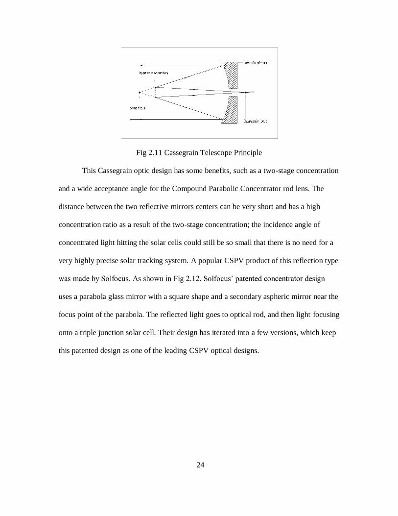
Fig 2.11 Cassegrain Telescope Principle
This Cassegrain optic design has some benefits, such as a two-stage concentration
and a wide acceptance angle for the Compound Parabolic Concentrator rod lens. The
distance between the two reflective mirrors centers can be very short and has a high
concentration ratio as a result of the two-stage concentration; the incidence angle of
concentrated light hitting the solar cells could still be so small that there is no need for a
very highly precise solar tracking system. A popular CSPV product of this reflection type
was made by Solfocus. As shown in Fig 2.12, Solfocus’ patented concentrator design
uses a parabola glass mirror with a square shape and a secondary aspheric mirror near the
focus point of the parabola. The reflected light goes to optical rod, and then light focusing
onto a triple junction solar cell. Their design has iterated into a few versions, which keep
this patented design as one of the leading CSPV optical designs.
25
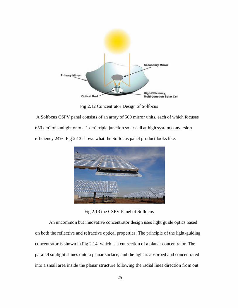
Fig 2.12 Concentrator Design of Solfocus
A Solfocus CSPV panel consists of an array of 560 mirror units, each of which focuses
650 cm2 of sunlight onto a 1 cm
2 triple junction solar cell at high system conversion
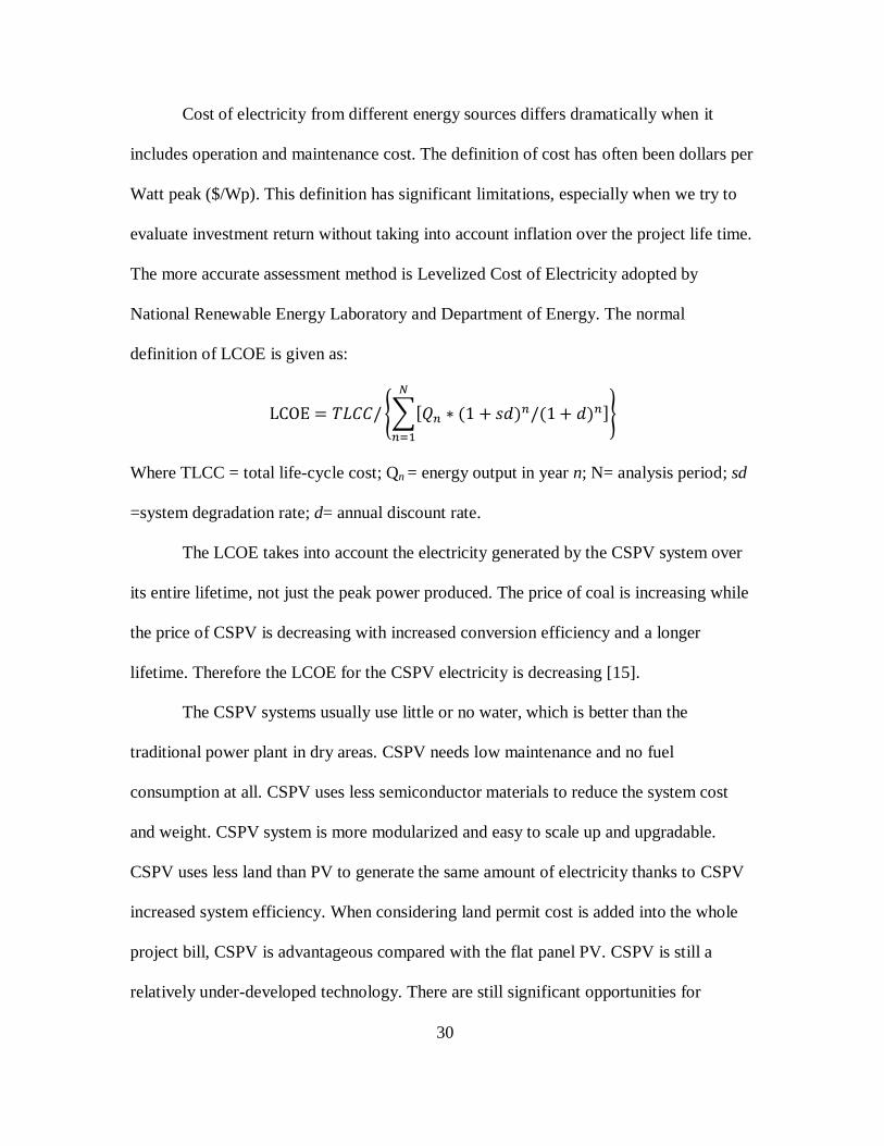
efficiency 24%. Fig 2.13 shows what the Solfocus panel product looks like.
Fig 2.13 the CSPV Panel of Solfocus
An uncommon but innovative concentrator design uses light guide optics based
on both the reflective and refractive optical properties. The principle of the light-guiding
concentrator is shown in Fig 2.14, which is a cut section of a planar concentrator. The
parallel sunlight shines onto a planar surface, and the light is absorbed and concentrated
into a small area inside the planar structure following the radial lines direction from out

26
layer toward the planar center. The concentrated light will exit from the output aperture,
and the solar cells are placed at the output exit. The highly concentrated light will strike
onto the multi-junction solar cells and generate electricity. This design has a big benefit
as it does not require a significant focal length between the focal point and the PV cell. A
company named Morgan Solar has been issued patents on this innovative concentration
design.
Fig 2.14 Concept of a Light-guiding Concentrator
Morgan Solar’s light-guiding optical structure is designed to trap the sunlight
striking onto the top of the concentrator (shown in Fig 2.15) with the help of the
reflective and refractive characteristics of its optic components, and to transport the lights
inside the optic concentrator to its center. The sunlight hits the reflective optical
components inside the planar concentrator, and keeps bouncing toward the center of the
concentrator, where it will hit the high-efficiency solar cells. Fig 2.16 shows a bundle of
parallel light trajectories among the array of circular grooves of the concentrator [13].
The L-shaped reflector has reflective surfaces which reflect the light onto the next L-
shaped reflector. The light will keep bouncing between the L-shaped reflectors and the
bottom reflector. From the top side of the concentrator, there is an array of the circular
groves which are made of the L-shaped reflectors endlessly connected together.

27
Fig 2.15 Light Guide Optical Concentrator module (from Morgan Solar)
Fig 2.16 Trajectories of Lights Travelling in the Concentrator
Advantages over the other conventional reflective or refractive concentrators
includes: a lower optical profile that uses less material, an equivalent or better
concentration factor and angular acceptance. The material used is ultra-thin, low cost,
lightweight, rugged, and long-lasting. The material selected for the optic parts is made of
acrylic and glass, and is therefore less expensive in volume production. It is also designed
for high heat, high wind-load, and extreme moisture conditions, leading to a low
maintenance cost. It could reach 1000 sun concentration ratio without using bulky
structure of the other concentrators. All this would help reduce CSPV system cost and
cost per kWh.

28
Another design uses luminescent solar concentrators. Sunlight is refracted in a
luminescent film and then being channeled towards photovoltaic material. As it does not
require optical lenses or mirrors, this design works with diffused light and hence does not
need solar tracking. This waveguide optics generally uses doped glass sheets or coated
with emissive materials. The radiated light is trapped in the waveguide substrate by total
internal reflection. The concentration factor usually is low with relatively cheap cost and
could increase the PV cell efficiency. There are a few companies developing different
film technologies. Covalent uses an organic film, while Prism Solar uses a holographic
film (shown in Fig 2.17). Another advantage of this type of design is that it does not need
cooling. Most of the luminescent solar concentrators require no tracking just redirecting
solar radiation into simple waveguides.
Fig 2.17 Principle of Holographic Film Concentrator
Another type of concentrator designs to achieve high solar flux include the Micro-
Optic Slab concentrator, (shown in Fig 2.18)which acts as a hybrid of
imaging/nonimaging optical system by combining an imaging lens array with a
multimode slab wave-guide. It has three main components: the first is a two-dimensional

29
lens array to collect the incident radiation; the second is a high refractive index slab
waveguide placed beneath the array. The top surface of the waveguide is separated from
the lenses by a thin, low-index cladding layer. The third component is a mechanism that
couples light into the waveguide. This concentrator integrates multiple, focusing
apertures with a common, multimode waveguide to direct solar energy to a single solar
cell. This system requires new fabrication and molding technologies, as well as a tracking
system to achieve the best output power [14].
Fig 2.18 Schematic of Micro-Optic Slab Concentrator
A lot of CSPV systems rely on bulky optics such as parabolic dishes or imaging
lenses. These elements can produce smaller image of the sun and yield high levels of
concentration, but produce non-uniform flux distributions and require very accurate
alignment. CSPV has a lot of economic advantages inherited from its PV characteristics
and it also offers benefits that normal PV cannot match in economics.
2.3 Economic Analysis of CSPV
30
Cost of electricity from different energy sources differs dramatically when it
includes operation and maintenance cost. The definition of cost has often been dollars per
Watt peak ($/Wp). This definition has significant limitations, especially when we try to
evaluate investment return without taking into account inflation over the project life time.
The more accurate assessment method is Levelized Cost of Electricity adopted by
National Renewable Energy Laboratory and Department of Energy. The normal
definition of LCOE is given as:
Where TLCC = total life-cycle cost; Qn = energy output in year n; N= analysis period; sd
=system degradation rate; d= annual discount rate.
The LCOE takes into account the electricity generated by the CSPV system over
its entire lifetime, not just the peak power produced. The price of coal is increasing while
the price of CSPV is decreasing with increased conversion efficiency and a longer
lifetime. Therefore the LCOE for the CSPV electricity is decreasing [15].
The CSPV systems usually use little or no water, which is better than the
traditional power plant in dry areas. CSPV needs low maintenance and no fuel
consumption at all. CSPV uses less semiconductor materials to reduce the system cost
and weight. CSPV system is more modularized and easy to scale up and upgradable.
CSPV uses less land than PV to generate the same amount of electricity thanks to CSPV
increased system efficiency. When considering land permit cost is added into the whole
project bill, CSPV is advantageous compared with the flat panel PV. CSPV is still a
relatively under-developed technology. There are still significant opportunities for

31
improvements in energy conversion efficiency and system cost reduction that will
strengthen CSPV market competitiveness.
Si-based LCPV systems providers like Solaria, Sun Power, Skyline, and others
could show great growth in the near future. In the meantime, dozens of companies are
working on developing products to participate in the supply chain. For multijunction
solar cell used in the HCPV systems, there are a lot of new developments in solar cell
research. More companies have shown the potential to make more than 40% efficient
solar cells, which will boost supply and drop price for high efficiency solar cell.
New trend of the industry toward standardization could further reduce the cost.
Companies servicing the CSPV supply chain are beginning to offer off-the-shelf optics
and testing equipment. This standardization could help speed up new product
development and reduce the cost. For a successful commercialization of the CSPV
technology, it is essential that the design and production work under standards and
norms. These will also help increase end-user confidence in the CSPV products.
Efficiency of most triple junction solar maximize at around 450 suns. A trade
space exists between the efficiency, absorber area, concentration, operating temperatures,
and ultimately cost. There will be new designs for higher temperature tolerance and
higher concentration operation. Further advances are additional junctions, better
antireflection coatings, and better transparent conducting oxides. It is expected that
HCPV cell, module and system efficiency will keep rising toward 50% and very soon
(Fig 2.19).

32
Fig 2.19 CSPV Cell, Module & System Efficiency Roadmap [17]
Unlike silicon industries, different HCPV technology uses different materials and
proprietary design and manufacturing technologies, which make HCPV less susceptible
to the material prices than the LCPV based on silicon solar cells. LCPV based silicon
solar cells have the potential to compete with HCPV technology. However, some silicon
based LCPV systems companies are switching to III-V mutlijunction-based HCPV
systems resulting in fewer LCPV producers (SunPower, NaREC, BP Solar, Q-cells). An
example is Amonix which currently has stopped producing the silicon solar cells module
based LCPV [16].
CSPV solar cell cost only account for a small part of the module cost, while the
other materials such as aluminum, steel, plastic and optical components are very
important. The balance of the system cost normally is more than solar module cost. The
CSPV industry is in its infancy in terms of efficiency, automation production and
manufacturing volume. A lot of gains can be made in different categories such as the

33
solar cell, balance of system, and initial investment. CSPV systems will start to challenge
the flat panel PV market position as soon as CSPV becomes price competitive.
In summary, this chapter went through one important part of a CSPV system
namely the solar concentrator optics. Different optics designs were discussed and
evaluated. The economic analysis on the new CSPV developing trend also revealed the
booming of solar power generation with lower cost and high efficiency new CSPV
systems.

34
CHAPTER 3
A CSPV SYSTEM CALLED THE SOLAR UMBRELLA
3.1 Concentrated Photovoltaics Generation unit
There is a demand for residential, off-grid solar power production system in high
direct normal irradiance areas, especially for the underdeveloped areas where the cost for
building utility scale electricity grid is so high that a better solution is to generate power
locally. The new power system can offer new alternative power solutions for people who
travel with Recreational Vehicles (RV), go hiking and camping, drive electrical vehicles
with need to charge car batteries. One solution to these needs is an innovative CSPV
design called the Solar Umbrella. It uses a light weight foldable and portable reflective
parabolic mirror for concentrating solar power onto a receiver module of high efficiency
solar cells. The Solar Umbrella could offer direct current (DC) or alternating current
(AC) to power electrical appliances. In addition, hot water can be produced via heat
exchange for reducing the temperature of the triple junction solar cells during electricity
generation.
The Solar Umbrella consists of two or three stages of concentrators, with dual
axes sun tracking system, power storage system, photovoltaic inverter and battery
charger. The concentrator first stage is a parabolic dish formed by multiple blades made
of polycarbonate. The second or third stage concentrators comprise the receiver which
adjusts the concentrated lights reflected from the first stage mirror to shine on the triple
junction solar cells. The solar tracking system ensures that the parabolic mirror faces the
sun for maximum exposure, and the power storage system includes batteries which store
unused power during daytime and output power after sunset.

35
3.2 Solar Umbrella Concentrator Designs
The Solar Umbrella’s function is to collect sunlight for generating electricity. A
high concentration ratio as much as 1000 times will help the triple junction solar cells
work better and output more power. The solar umbrella has 2 different versions, one with
1 meter diameter, and the other 4 meters diameter. The expected power output of 1 meter
is 150 Watts using 6 triple junction solar cells, while the 4 meter version is expected to
get peak power 3000 Watts using 120 triple junction solar cells. The solar cell type is
CTJ receiver assembly from Emcore. The cell has 37% conversion efficiency at 25
degree Celsius ambient temperature under the standard AM1.5 spectrum.
The basic idea of concentrating in the Solar Umbrella (SU) is using a parabolic
dish to concentrate sunlight at the first stage, and then use the designed receiver to do the
second stage or even third stage concentration. Fig 3.1 shows the schematics of an
unfolded and folded solar umbrella. The open umbrella’s parabolic mirror could reflect
and concentrate sunlight to the focal point of the mirror surface. The folded umbrella
could fit into a cylindrical container for easy transportation.
Fig. 3.1 the Concept of Unfolded and Folded SU

36
The first stage concentrator is the parabolic reflective dish formed by a number of
same sized rigid sections of partial parabolic surface with the same focal point up over
the centre of the dish. On the principle of optics and geometry, the parabolic mirror dish
surface profile satisfies the equation x2+y
2=4pz in the Cartesian Coordinates (x, y, z)
(shown in Fig 3.2). The sunlight comes parallel with the z-axis, and shines onto the
surface, then reflects onto a single focal point at (0, 0, p). Since the sun is not exactly a
point source, the image of the sun, which is made of the concentrated sunlight at the focal
point, is not a single point. The concentration ratio of sunlight on the Earth has a
limitation due to both the distance between the Sun and the Earth and their dimensions,
and it should be less than 40,000 times.
Fig 3.2 Parabola Dish Geometry
The second stage concentration could be fulfilled by the conic shape reflector
(shown in Fig 3.3) which stays before the focused light come to the focal point, and
finally the concentrated sunlight will hit the solar cells after being adjusted by the second
stage concentrator.

37
Fig 3.3 Two-Stage Concentrator Concept
The 4-meter dish has a flat reflective receive area of A=πr2=12.57 square meters
as shown in Fig 3.4. The second stage conic receiver has a flat receiving area A1=
=0.20 square meters with a 0.5 meter diameter. The solar cells are arrayed at a flat
circular area of A2 = =0.012 square meters with 0.125 meter diameter.
Fig 3.4 Concept Diagram of the Concentrator

38
It is assumed that all sunlight reflected by the first stage parabolic concentrator A
is collected by the second stage concentrator A1, with all collected light further
concentrated onto the solar cells of area A2. The first stage concentration ratio is A/
A1=64, and the second stage concentration ratio is A1/A2=16, resulting in a combined
concentration ratio of 1024=64*16.The conical second stage concentrator makes a
shadow onto the first stage concentrator, thereby reducing the amount of light received by
each corresponding area A, A1, A2. All active reflective areas are reduced proportionally
by the holes at the center, resulting in the unchanged concentration ratios.
Consider the three parabolas shown in the above picture with the same focal point
F, the radii of parabolas are denoted as r, r1 and r2. The vertical displacements: q, q1, q2
are measured from the focal point of the big parabola to the center of the three parabolic
surfaces O, O1, O2. The flat light receive areas of parabolic surfaces are given by A, A1,
A2. These three parabolas are called co-focal, meaning that the theoretical concentration
ratio of the Solar Umbrella would be around 1000 suns assuming negligible optical
reflection loss.
Fig 3.5 Efficiency verse concentration for multi-junction cells

39
The high concentration ratio will help the triple junction solar cells achieving
better conversion efficiency. This has been demonstrated by the Fraunhofer Institute of
solare energiesysteme’s triple junction solar cells as shown in Fig 3.5 for efficiency
versus concentration diagram.
Fig 3.6 it shows that light can be further concentrated by the second surface onto a
third surface where the solar cells array is placed. The incident light should be as
perpendicular to the solar cells as possible. The third surface can be a spherical surface
centered at point F instead of the co-focal parabolic surface. Each cell has its own cone
concentrator which captures light from a specific part of the second surface area and
adjusts the light onto the solar cell. The cones can be designed in various geometries,
including pyramidal section, sectional cone and hyperbolic trumpet cone concentrator
(shown in Figure 3.7). The edge of the outside cones could use additional compound
parabolic conic shape to capture some stray lights.
Fig 3.6 Schematics of Concentrator Cones Design (Front and Isometric views)

40
Fig 3.7 Geometries for the Cones
The first reflective parabolic mirror with area A, second stage parabolic mirror
with area A1 and a bottom flat mirror for a Newtonian reflective telescope can help us
understand multi-stage light concentration (shown in Fig 3.8). The two parabolas are co-
focal on the focal point F. The lights converge when being reflected upward toward the
focal point. Light diverges when reflected downward. The combined convergent and
divergent mirrors setup helps the telescope structure obtain a magnified light intensity
ratio of A/A1.
Fig 3.8 Schematic of Newtonian Telescope

41
The three stage solar concentrator design is the adaption of the Newtonian
telescope concept, with a bottom parabolic mirror reflecting sunlight upward, a top
parabolic mirror reflecting the focus light downward and a conic concentrator in the
center of the first parabola surface. The almost straight concentrated light will go to the
array of solar cells at the bottom of the third stage conic concentrator (showed in Fig 3.9).
Fig 3.9 Geometry of Three Stages of Solar Concentration
The mathematics of combined focal length of compound lens or mirror telescope
is well known. I derived here the optics in this special context of solar PV electricity
generation.
A Cartesian coordinate system is used for the derivation (Fig 3.10). The parabola
surface center point O is defined as origin (0, 0, 0), the focal point F is at (0, 0, f1). The
focal length of the top mirror is f2. The top mirror center is placed at (0, 0, f1–f2), so that
light reflected off the top mirror would travel parallel and straight down. If the top co-
focal mirror is moved up by a distance of ε, the focal point of the compound mirrors now
shift up from -∞ towards point O. Suppose that new focal point with this shift is at (0, 0,

42
f), and the vertical distance between the two parabola surfaces is d. An equation
is obtained, where .This equation for f can be proved for special
cases .
Fig 3.10 Two Co-Focal Parabolas
If ε = 0 as in the case of Newtonian telescope, then it could get that f = - ∞. If d =
f1, then and
, which indicates that the combined
focal length is at the center of the second parabola, now placed at the focal point of the
first parabola. Then indicates that as shifting the second mirror up, the focal point f has
moved from -∞ upward. To obtain a desirable f the shift ε needed can be achieved by
solving the pair of simultaneous equations
and . In practice
for ε = 0, I can place at O to concentrate light by means of reflection onto a single chip at
(0, 0, 0). Similar arrangement can be made for multiple cells.
The solar umbrella could be folded and unfolded to make it more suitable for
portable solar power generation. The design of the folding mechanism for the umbrella is
a challenging problem. Many attempts were tried and some were prototyped, and the
single axis folding method of blades of umbrella is a choice for its simplicity. The blades

43
are packed in a way that the length of the blades is aligned with the center support and the
width of the blades is aligned in a radial direction. The blades rest on different angles of
inclination towards the center, and fold toward the center which is similar to the folding
of petals of the flower rose.
Figures 3.11 and 3.12 show that the design of the 1 meter prototype solar
umbrella of 18 folded blades is arranged into 4 layers. Each blade has the same cuff
mechanism holding onto the center platform to allow the blades to move towards the
center. The solar receiver is close to the focal point of the opened parabolic mirror made
of 18 rigid blades. This four layer folding geometry (shown in Fig 3.13) is the best
symmetry discovered yet for the purpose of compact folding. The choice of 18 blades is
given by 18=6+6+6, with three concentric layers each with 6 folded blades. The
innermost layer of 6 blades could be more compactly folded if it is divided into two
layers of 3 blades and then the 3-layer design is evolved into a more compact 4-layer
design.

44
Fig 3.11 the Folded 1 Meter SU Prototype
Fig 3.12 Unfolded 1 Meter SU Prototype

45
Fig 3.13 Folding Layers Geometry
3.3 CSPV Tracking Systems
As PV cells generate current, solar cells could be modeled as DC current sources.
The amount of current a PV panel produces is directly correlated with the intensity of
light the PV cell absorbed. For example, the normal to the PV cell is perpendicular to the
cell's exposed face (shown in Figure 3.14). When the sunlight is assumed at a constant
intensity, the available sunlight to the solar cell for power generation can be calculated:
, where A represents the limiting conversion factor in the design of the
PV cells.

46
Fig 3.14 Principle of Intensity of Light on PV Cell
Figure 3.15 shows that off axis angle of acceptance affect a maximum power of a triple
junction solar cell.
Fig 3.15 Output Max Power versus Angle Degrees off Axis
The solar tracker could be divided into two categories - one is active tracker and
the other is passive tracker. Active tracker is directed toward the sun by electrical
circuitry in the form of light-sensing photo sensors. Motors and gear trains are then used
to direct the tracker as commanded by the photo sensors to the sun’s direction. Passive
tracker uses mechanisms or materials that respond to heat of the sun, if there is heat
imbalance, the mechanism or material will correct the imbalance by facing the panel
towards the sun.

47
For a given concentration ratio, different concentrator optics design will provide
different acceptance angles for the PV solar cells. In a typical high concentration system,
the tracking accuracy must be in the ± 0.1° range to deliver approximately 90% of the
rated power output. In a low concentration system, the tracking accuracy must be in the ±
2.0° range to deliver 90% of the rated power output. As a result, high accuracy tracking
systems are typically used in the big PV panel which has a high power output.
3.4 Solar Tracking Systems Review
Single axis trackers
Single axis trackers have one degree of freedom that acts as an axis of rotation.
The axis of rotation of single axis trackers is typically aligned along a true North
meridian [18]. It is possible to align them in any direction with advanced tracking
algorithms [19]. There are several common implementations of single axis trackers [20].
These include Horizontal Single Axis Trackers (HSAT), Vertical Single Axis Trackers
(VSAT), Tilted Single Axis Trackers (TSAT) and Polar Aligned Single Axis Trackers
(PSAT)[21].
Horizontal single axis tracker (HSAT)
The axis of rotation for horizontal single axis tracker is horizontal with respect to
the ground (Fig 3.16). The posts at either end of the rotation axis in a horizontal single
axis tracker can be shared between trackers to lower the installation cost.

48
Fig 3.16 Horizontal Single Axis Tracker
Vertical single axis tracker (VSAT)
The rotation axis in vertical single axis trackers is vertical with respect to the
ground (Fig 3.17). These trackers rotate from East to West over the course of the day.
Such trackers are more effective at high latitudes than horizontal axis trackers.
Fig 3.17 Vertical Single Axis Tracker
Tilted Single Axis Tracker (TSAT)
The TSAT axis of rotation is neither horizontal nor vertical with respect to the ground; it
is at any angle between horizontal and vertical with the face of the solar panel array

49
oriented parallel to the axis of rotation (Fig 3.18). As the system tracks, it sweeps a
cylindrical arc to track the visible motion of the Sun throughout the day. All trackers with
axes of rotation between horizontal and vertical are considered tilted single axis trackers.
Tracker tilt angles are often limited to reduce the wind profile and decrease the elevated
end’s height off the ground.
Fig 3.18 Tilted Single Axis Tracker
Dual axis trackers
Dual axis trackers have two degrees of freedom that act as axes of rotation. These
axes are typically normal to one another. The axis that is fixed with respect to the ground
is considered a primary axis. The axis that is referenced to the primary axis is called a
secondary axis. There are several common implementations of dual axis trackers. They
are classified by the orientation of their primary axes with respect to the ground. Two
common implementations are Tip-Tilt Dual Axis Trackers (TTDAT) and Azimuth-
Altitude Dual Axis Trackers (AADAT).
Tip-Tilt Dual Axis Tracker:

50
A TTDAT tracker has its primary axis horizontal to the ground. The secondary
axis is then typically normal to the primary axis (Fig 3.19). The posts at either end of the
primary axis of rotation of a TTDAT can be shared between trackers to lower installation
costs.
Fig 3.19 Tip-Tilt Dual Axis Tracker
Azimuth-Altitude Dual Axis Tracker:
An AADAT has its primary axis vertical to the ground. The secondary axis is then
typically normal to the primary axis (Fig 3.20). The main difference between AADAT
and TTDAT is the way the panel rotated for daily tracking. Instead of rotating the array
of panel around the top of the pole, AADAT typically uses a ring mounted on the ground
with the panel array mounted on a series of rollers. The AADAT could support larger
arrays than TTDAT which stand on single loading point of the pole.

51
Fig 3.20 Azimuth-Altitude Dual Axis Tracker
The dual axis trackers are used not very widely due to the cost and the economic
tradeoff behind the technology. Both the single axis and dual axis trackers have
disadvantages, such as the adoption of tracking system will incur more upfront cost and
the tracking systems components need maintenance. Also the added moving parts will
increase system complexity and reliability. Finally compared to permanent mounts, the
sun tracking structure is less rigid and more vulnerable to weather-related damage.
3.5 Solar Umbrella Dual Axis Tracking
The Solar Umbrella system needs dual axis tracking based on principle as the
azimuth and altitude dual axis tracker. The goal of the tracker for Solar Umbrella is to
design an active and dual axis solar tracker with an allowable error of 0.1°.The use of
tracking system in the CSPV system greatly improves the power gain from solar radiation
[22].

52
This dual axis tracking system includes the following components:
1. Sun tracking algorithm: the algorithm [23] calculates the azimuth and zenith angles of
the sun. The two angles are then used to position the solar panel or concentrator toward
the sun. The algorithms are pure based on astronomical references while others use real
time light intensity readings. The algorithms also need to compensate the atmospheric
refraction.
2. Control unit: the control unit executes the sun tracking algorithm and coordinates the
movement of the electrical positioning system. It can be implemented in programmable
logic controller (PLC), industrial personal computer, or microcontroller platforms.
3. Electrical positioning systems: the system moves the panel or reflector to face the Sun
at the optimum angles. This positioning system utilizes encoders and variable frequency
drives or linear actuators to monitor the current position of the panel and move to the
desired positions.
4. Drive mechanism and transmission: the drive mechanisms may include linear
actuators, linear drives, worm gears, planetary gears, and threaded spindles.
5. Sensing devices: for trackers that use light intensity in the tracking algorithm,
pyranometers are needed to read the light intensity. Ambient condition monitoring for
pressure, temperature and humidity may also be used to optimize the efficiency and
power output.
Since the Solar Umbrella needs to easily set up automatic finding its location and
unfold when wind speed is too high. The control platform uses the Global Positioning
System chip, electronic compass and anemograph instrument to implement the automatic
deployment of the solar umbrella and safety protection features.

53
The dual axis solar tracker for the solar umbrella is implemented using a special
tracking control algorithm that is a hybrid between open loop and closed loop control.
Open loop control is needed because the sun can be obscured by clouds, eliminating or
distorting the feedback signals. The electrical positioning system needs to actively follow
the sun’s position even when there is no sun detected during the day. The open loop
means that the control unit sends motion control commands to the motor and driving
mechanisms to move to the calculated sun’s position regardless. The closed loop
component requires adjustments, which needs to get the real accurate sun position from
the sensors and then predict how to get the best solar radiation then move the motors.
This closed loop control adjusting process is imperative to reduce the accumulated error
from the driving motor, gears and other mechanisms. The two motors can be operated
manually; alternatively I can use photo sensors to detect the sun position, and control the
two motors with analog signals. The prototype concept is shown in the Fig 3.21. The
parabola dish on top of the support base simulates the unfolded solar umbrella’s first
stage reflective surface. There is a photo sensor module on the rim of the dish which
could tell the sun’s position or whether normal to the sun.
Fig 3.21 Dual Axis Tracking Test Platform

54
The solar umbrella tracking system used two DC gear motors and microcontroller
based printed circuit board platform which could output digital signals and with input
digital and analog signals from all the sensors(Fig 3.22). The control algorithm
implements the open loop and closed loop system hybrid method to track the sun with
high resolution of accuracy.
Fig 3.22 Solar Tracking Control Blocks
The tracking system positioning control algorithm is implemented on the
microcontroller platform with communication with GPS chip to get time and location
information and compass chip to get the dish orientation angle information to
automatically calculate the solar position using the algorithm provided by NREL. The
diagram of the system logic is showed in Fig 3.23.

55
Fig 3.23 Diagram of the SU positioning system
The tracking system control unit will implement other special functions into the
microcontroller which was chose from open source Arduino. Safety issues mandate the
umbrella to unfold itself in high wind. It also needs to monitor the solar cell temperature
to adjust the speed of coolant circling.

56
CHAPTER 4
A CONCENTRATED SOLAR THERMAL POWER SYSTEM
4.1 The CSTP System Components
I studied a concentrated solar thermal power generation system, which includes
the following components connected based on the energy flow in the system (shown in
Fig 4.1):
Fig 4.1 the Designed CSTP Structure
1. Optical solar concentrator could be made by glass or metal with reflective surfaces in a
parabolic dish shape. The concentrator dish can be a reflective film backed by
polycarbonate or carbon fiber composite material.
2. The solar thermal boiler for collecting heat energy from concentrated sunlight heat or
from a backup natural gas furnace fire and it will heat up water to high pressure, high
temperature steam.
3. The disk type micro turbine converts the heat of high pressure and temperature steam
into kinetic energy.
4. The wasted heat reuse and steam condensation is can be used for water heating or solar
air conditioning applications to increase the whole system energy using efficiency.
5. The AC generator converts the kinetic energy of the rotating turbine into AC current,
which is grid-tied to the generating of the power grid.
The sun Solar Concentrator Boiler Turbine Generator
Heat reuse and condensation High pressure water pump

57
4.2 CSTP System Modeling
The solar energy to electric energy conversion efficiency can be calculated from
losses due to the optical reflectors, thermodynamic engine, and the AC generator. It can
start from a certain amount of solar energy shining onto the concentrator. Power is
reduced after each light reflection, and finally light hit on the surface of the boiler. Light
is then transferred into heat to cold water in the boiler. It has heat loss by convection,
radiation and transportation. The steam comes through pipes to the steam turbine. Part of
the energy is converted to useful kinetic energy to the generator. The AC generator
converts the kinetic energy into an electric current, with conversion loss from internal
resistance and friction.
Steam exiting from the turbine may be used to heat water prior to its entry to the
boiler, or used for other purposes such as absorption chilling and household heating. The
steam eventually condenses and is collected in a reservoir of water. The Rankine cycle of
water then repeats again: water pumping, heating to form high pressure and temperature
steam, work producing through a turbine, and condensation.
Optical Solar Collector
The accuracy of the parabolic mirror profile determines how well the focusing the
dish could achieve. To concentrate the sunlight perfectly- wavelength is ranging from
400 to 700 nanometers (nm), the reflector surface must be corrected within about 20 nm.
I also consider reflectance and emittance of the reflecting materials.
The method used in this research to test the accuracy of the parabolic dish is laser
rays tracing. I set up the reflective dish indoor with multiple point laser pointing
vertically downward rays to the dish from ceiling height to examine how accurate the

58
reflected laser light may be focused at the focal point. Two types of solar concentrator
optics were tested: a customized reflective sheet with polycarbonate support made by
chemical vapor deposition on the front surface, and commercial solar concentrator
polished film on aluminum support made by 3M. I also measured the reflection of the
material. The data collected from the transmission and reflectance measurements
indicated a significant amount of light was absorbed close to 60% at wavelength
400nm.The second sample showed the reflectance meet what was claimed in the product
brochure.
Disk Type Micro Turbine
Micro turbine is a new method to allow distributed power generation at homes.
Micro turbines generate KiloWatts of power output instead of MegaWatts of power for
utilities. Micro turbine has the advantages of less moving parts, compact size,
lightweight, good efficiency, low electricity cost, and less maintenances. The micro
turbine can be gas turbines or steam turbines using air or water as the heat transfer
medium.
One example of utility scale turbine is the Combined Heat and Power (CHP)
style turbine built by Capstone Turbine Corporation. Capstone Turbines could use
alternative fuels to provide power and heat in remote areas. These smaller turbines have a
lot of uses in military field including Unmanned Aerial Vehicles (UAV), missiles, and
remote control aircraft.
For smaller turbines called nanoturbine can be very small in dimensions. One
small turbine is built at MIT by Professor Alan H. Epstein. Nanoturbines aimed for small
wattage power output based on the manufacturing technology called Micro Electro

59
Mechanical Systems (MEMS). The goal is to reach to around 10 Watts or less of power
to support personal daily power needs
In this thesis I focused on the disc type micro turbine. One very common disc type
micro steam turbine is the Tesla turbine invented by Nikola Tesla in 1913. The Tesla
turbine combines a stack of smooth round disks, with nozzles blowing a high speed
steam/gas to the edges of the disks. The gas drags the disk by means of viscosity and the
adhesion of the gas with disk surface. The gas exhaust exits from the center of the disk.
At low Reynolds number (Re=Initial force/Viscous force), the boundary layer effect is
most effective for momentum transfer of the Tesla turbine. This Tesla turbine is an
efficient self-starting prime mover for power generation
There are three basic types of turbines: impulse turbine, reaction turbine, and lift
turbine. Here is a diagram to show the difference function principle of the first two main
types of turbine (showed in Fig 4.2)
Fig 4.2 Turbine Function Principle Diagram

60
The main distinction between impulse and reaction turbine is the manner in which
the steam is expanded as it passes through the turbine. For the impulse turbine, the hot
and high pressure gas expands when passing over the turbine blades. The speed up gas
imparts momentum to turbine blades by means of impact. In reaction turbines, the steam
is continually expanding as it flows over the blades. The blades are lifted and rotates
similar to the differentiate pressures on opposite surface a turbine blade. The De Laval
turbine is an impulse turbine with a single blade wheel. The Charles Parsons turbine is
one typical example of the reaction turbine.
Tesla turbine is a radial turbine in which the flow of the working fluid is radial to
the shaft. The disk type micro turbine is invented with the objective to best utilize the
pressure energy of high temperature, high pressure superheated steam or gas. The turbine
converts high pressure steam to mechanical torque. A hot gas is expanding through the
spiral shape micro-tunnel to drive the turbine rotating at a certain speed range. The gas
performs work through adiabatic expansion. The prototype disc steam turbine is made of
stainless steel by Electro Discharge Cutting Machine (EDM) technologies.
The figure 4.3 shows a long spiral channel for gas flow. The gas flows from the
center in the spiral micro-tunnel of the turbine, and expands through the long channel,
finally reach the exit. The hot and high pressure gas drives the turbine to rotate. The gas
will gradually drop its high pressure and expands adiabatically with lowered temperature.
For the linear spiral micro tunnel shown in Fig 4.3, It has r (θ) =10+2.5θ/π for the
ten turns made for 0<θ<20π. At the inlet of the spiral, it has r (0) =10mm. At the outlet
with r(20π)=60mm, the length of the infinitesimal length of the spiral dL(dL= r(θ)dθ) has

61
expanded by a factor of more than 6, close to the factor of 10 increase in volume for the
gas as pressure is reduced from 20 atmospheres to 1 atmosphere.
Fig 4.3 Spiral Shape Micro Tunnel
The turbine consists of layers of stainless steel discs, top and bottom caps. There
are spiral shape micro tunnels cut off on each disk layer. The top cap has a steam inlet in
its center, while the bottom cap has an extended shaft hooked to the driving shaft of
generator. The disk type micro turbine could use a combined burning furnace and the
sunlight concentrator to heat up water in the two stages boiler and get the high pressure
superheated steam. The disk type turbine converts thermal energy in pressured steam into
useful mechanical work.
I examined the thermodynamics of the expanding gas in the spiral tunnel. As the
gas spirals outward, gas molecules are forced to change course defined by the boundaries
of the spiral. The outward spiraling flow of gas has a feature suitable for the adiabatic
expansion of the gas. Assume that the infinitesimal length of steam at radius
contained inside the infinitesimal angle . It can be calculated

62
that . As the gas travels outwards on the spiral with
increasing , it expands in volume as pressure is reduced. For this linear spiral, the
function and its first derivative are positive functions of . Therefore,
increases as increases. The gas expands within the expanding as it spirals outwards.
The gas volume expands as it moves through the spiral (As Constant,
where
for air/steam or mono-atomic gas respectively). I express volume as
function of pressure (for initial and final values subscripted by 1 and 2), it has
.
Consider gas counter clockwise flowing in the spiral, turbine which is turning in a
clockwise direction. As the turbine turns faster, the gas as seen outside the turbine is
spinning at a slower angular velocity as canceled by the turbine spinning .In essence, the
spinning turbine causes the gas exit and shortens the distance traveled by the gas.
4.3 Analysis of Micro Disc Turbine
It can use a Rankine cycle for the disk turbine which using circling water to
transfer energy from a high temperature heat source.
The Rankine cycle has five progressive stages in this design:
1. Cool water is pumped at high pressure into a boiler;
2. The water is heated and evaporated at high temperature, becoming saturated steam;
3. The steam is further heated to become superheated;
4. The high pressure steam is admitted the steam turbine through its center entrance
where steam spirals through to its low pressure end.

63
5. The steam condenses, and the cool water recycles through the pump.
Electricity is extracted from the generator which is directly coupled to the shaft of the
turbine. The Rankine cycle is shown in Fig 4.4.
Fig 4.4 Rankine Cycle Stages
Work generated equals to the energy entering the turbine as steam (with enthalpy
h1) minus the energy leaving the turbine as steam (with enthalpy h2) after expansion.
Heat transfer from the furnace (or the solar thermal concentrator collector) will be the
difference in the enthalpy of the steam leaving the boiler and the water entering the boiler
(h1-h3).The ratio of output work/input by heat transfer is the thermal efficiency of the
Rankine cycle, with Rankine thermal efficiency = (h1-h2)/ (h1-h3).
The momentum transferred to the disk with the interactions between the spiral
walls and the steam molecules as the steam passing the long resistive tunnel. The turbine
rotates in the reverse direction to the steam exiting direction from the turbine. For Tesla
turbine, the boundary layer effect is more efficient at low flow pressure and momentum
transfer. Our turbine works better under slow pressure reduction at a low rotational speed
than conventional turbines.

64
The Navier Stokes equation can be used to explain the motion dynamics happened
to the steam flowing in the steam turbine. The assumption of an incompressible gas with
Newtonian flow (fluid density and dynamic viscosity are constant), with a velocity
field was made, where ( is the cylindrical coordinate direction.
Vector form:
Where standing for the body force such as gravity or centrifugal force. This is a
statement of the conservation of momentum in a fluid applying the Newton’s second low
to a continuum.
The incompressible continuity equation:
r-component:
θ-component:
z-component:

65
Where gravity components ).
The energy input to our turbine is about 10Kw solar energy contained in the heat
of the superheated steam generated by 2cc of water per second. The total enthalpy of
steam at 20 atmospheric pressure and 800 degrees Kelvin is about 3.5KJ /cc of water.
The 2cc volume of water could generate around 400 cc superheated steam with total
enthalpy of 7 KJ. It is expected exiting gas with a temperature around 400 degrees Kelvin
at 1 atmosphere in pressure.
4.4 Disk Micro Turbine Prototyping and Test
CAD modeling and simulations are made to validate the turbine design. The first
stage of design concept was to build a straight radially expanding circular tunnel as
shown in Fig (4.5.a).This concept is a variation from the Hero turbine. The other concept
tested included a 3 spiral shape axisymmetric tunnels with a circular cross section cutting
off area formed by two disks stacked together (shown in Fig. 4.5.b).The air comes into
the center chamber and exits through the 3 tunnels simultaneously. Another design
showed in Fig 4.5.b, which aimed to increase the impedance of the gas tunnel by using
contraction nozzle with variable cross section areas for the whole spiral length is shown
in Fig (4.5.c). These designs were built using a 3D printer using for PVC plastic material.
These prototype turbine designs were tested using high pressure compressed nitrogen gas,
and then connected to a DC motor to generate the electricity. The test results showed that
the rotating speed of the turbine is relatively higher than the expected design rotation
speed which is around 3000 rpm. The power output from the DC motor is positively
proportional to both the input nitrogen gas flow rate and pressure.

66
Fig 4.5, Turbine Concept CAD designs (from left to right 4.5.a, 4.5.b, and 4.5.c)
To reduce the high rotation speed, methods were used to slow down the rotation
speed and increase kinetic to electrical conversion efficiency. Figure 4.6.a demonstrated
the design of 3 turn spirals through the disk. The thickness of the designed disks is
increased from 6mm (Fig. 4.6.a) to 12.7mm (Fig. 4.6.b, Fig. 4.6.c).The design of Figure
4.6.b also has a decreased width of the cross section area of 0.5mm width. The latest
design is shown in Figure 4.6.c, which has only one spiral but with 10 turns.
The test of the turbine is built on a special test setup which has the turbine axle
aligned with the generator shaft. The testing steps are as follows: prepared first the DC
motor, I then applied the gas to measure the speed of the turbine using a tachometer and
last measured the voltage at the motor terminals for various resistor loads.
Fig 4.6 the Disk Turbine Evolved Designs (from left 4.6.a, 4.6.b and 4.6.c)

67
Fig 4.7 showed the setup for the testing of disk type turbine designed based on the
concept of Fig 4.3. Gas comes in from the right side, and the generator is shown on the
left side, in the middle is the testing turbine built by our 3D printer. The turbine uses a
tube to guide the gas into the turbine within a shaft to drive the generator set. The turbine
includes two disks stacked up. The exits are on opposite side of the disks. The gas is
injected through a nozzle into a female cavity of the turbine. Some gas leaks occur which
functions as a gas bearing.
Fig 4.7 Disk Type Micro Turbine Testing Setup
The turbine has only been tested using the compressed nitrogen gas. The boiler
has already been built, but the stainless tube superheating coil has experienced some
metallic flaking issue when intense heat wave applied. The DC motor internal resistance
is tested 23.4 Ohms. The formed gas bearing leakage was so hard to control as if the seal
gap is too tight that there was high friction force. The friction force tended to be small
when rotate at higher flow rate with high rotating turbine speed. I tested the DC motor
terminal voltage for open circuit situation and also with a value of 100, 50, 10, 5, 1 Ohms
respectively resistance added between the terminals. The testing compressed nitrogen gas
pressure is stable at 300 PSI with varied gas flow rate from 2.5 to 7.5 CFM (cubic food

68
per minute).Fig 4.8 shows the turbine ration speeds versus varied input gas flow rate to
the turbine under open circuit and with different resistance situations. Fig 4.9 shows the
voltages generated at the load with varied gas flow rate under the similar different loads
situation above mentioned.
Fig 4.8 Rotation Speeds versus Varied Gas Flow Rate
Fig 4.10 Voltages versus Varied Gas Flow Rate
0
1000
2000
3000
4000
5000
6000
2.5 3 3.5 4 4.5 5 5.5 6 6.5 7 7.5
open
100ohm
50ohm
10ohm
5ohm
1ohm
rpm
cfm
0
2
4
6
8
10
12
14
2.5 3 3.5 4 4.5 5 5.5 6 6.5 7 7.5
open
100ohm
50ohm
10ohm
5ohm
1ohm
Volts
cfm

69
Consider different load resistance and the DC motor internal resistance together, I
can calculate the overall system equivalent resistance with varied load conditions. Fig
4.10 showed the power generated from the turbine DC motor system with each load
situation under varied input gas flow rate.
Fig 4.10 Power versus Varied Gas Flow Rate
Software tools are available for computational fluid dynamic analysis of the steam
flow in the designed turbine. The turbine tests and simulations have validated the
methods of using narrow width, long spiral length and many turns to improve the micro
tunnel impedance on the rotation speed reduction. But further extensive tests need to be
done on the steam turbine built by stainless steel using the superheated steam.
In summary, an experimental design of a CSTP system was implemented based
on parabolic solar concentrator, boiler, disk type turbine and generator platform which
has been tested and evaluated in different testing situations. The small bladeless turbine
0
1
2
3
4
5
6
3 3.5 4 5 5.5 6 6.5 7 7.5
100ohm
50ohm
10ohm
5ohm
1ohm
Watts
cfm

70
has been tested and proved it can perform designed objectives. There will be more
continue simulation and testing involved with the new turbine to further improve the
energy conversion efficiency.

71
CHAPTER 5
CONCLUSION
In this research, the solar energy research meaningful point is discussed. I
discussed the most promising technology-concentrating solar power generation which
includes CSPV and CSTP. The two testing concentrated solar power generation systems
are implemented and validated in different situations.
The CSPV system includes two important parts: one is the concentrator optics,
and the other is solar tracking system. Various types of solar concentrator designs are
reviewed in terms of their performance and characteristics. The very common
concentrator optic is refractive (e.g. Fresnel lens) and reflective (e.g. Parabola dish)
optics .The innovative design using light guide optic provided a new solution for the
concentrator design.
The Solar Umbrella system is a portable and light-weight CSPV aims for some
distributed solar power generation applications. It uses two stages concentration optical
systems. The first stage is formed by 18 blades of reflecting parabolic mirror, while the
second stage is a reflecting cone to further concentrate and also evenly adjust the
concentrated sunlight shining onto solar cells. The Solar Umbrella uses a dual axis
tracking system to attain higher power output. The solar umbrella uses the azimuth and
elevation dual axis tracking and its hybrid digital control system uses both open loop and
closed loop system. The tests and data collected from the implemented Solar Umbrellas
system has proven the design objects.
Future work of the Solar Umbrella would be the power inversion and power
storage system. The power inversion includes the DC-AC inverter design. The power
storage means using (e.g. lithium-ion) batteries to store the electrical power generated by
the CSPV system. Also the charging and monitoring of battery system to extend the life
of battery could get the best performance of the battery system.
The implemented CSTP system is a boiler, turbine and generator type. A typical
disk type micro turbine was designed and tested to convert the high pressure and
temperature gas from the boiler. The CSTP system was based on using solar energy to

72
heat up a heat medium (water) to transfer the energy to a heat engine (turbine), and then
transfer the heat engine mechanical output to drive a generator to get power output.
CSTP is similar to CSPV as it needs similar solar concentrating optics and dual
axis solar tracking system. But the CSTP has an advantage compared with the CSPV, as
it collects the energy in the form of heat which is easy to recollect the waste heat which
could be used for other purpose. This feature will help CSTP system reaches to a higher
overall system energy conversion efficiency than CSPV which relying most on solar cell
modules conversion efficiency. The designed micro turbine based energy system has
proved the design objectives. The discussion on the CSTP systems provided the core
technology and trending researching topics in the concentrated solar power generation
field.
There will be further computational fluid dynamic (CFD) research using
commercial CFD simulates software to test the turbine performance under varied high
pressure and high temperature situations. Also the turbine will be tested on different heat
mediums as well. There should be more extensive optimization in mechanical design,
materials selection, and manufacturing process for the CSTP system.

73
REFERENCES
[1] Adrian Catarius, et al. Azimuth-Altitude Dual Axis Solar Tracker. Worcester:
Worcester Polytechnic Institute, 2010.
[2]"Renewable energy." http://en.wikipedia.org/wiki/Renewable_energy (accessed Oct
14, 2011).
[3] "Solar Energy." http://en.wikipedia.org/wiki/Solar_energy (accessed Oct 14, 2011).
[4] S.Kurtz. Opportunities and Challenges for Development of a Mature Concentrating
Photovoltaic Power Industry. NREL, 2008.
[5] Karmen, Daniel. An Assessment of The Environmental Impacts of Concentrator
Photovoltaics and Modeling of Concentrator Photovoltaic Deployment Using the
SWITCH Model. CSPV Consortium, 2011.
[6] Karp, Jason. Concentrating Solar Power:Progress and Trends. Feb 12, 2009.
[7] Solar Energy Industry Association, Solar Energy Facts: Q2 1013, Sep 2013.
[8] U.S. Energy Information Administration ,Electricity Power Monthly with data for
July 2013, Sep 2013.
[9]Hector Cotal, et al. "III-V Multijunction Solar Cells for Concentrating Photovoltaics."
The Royal Society of Chemistry, 2009: 175-176.
[10]Friedman, Dan. National Solar Technology Roadmap: Concentrator PV(Draft
Version). NREL, 2007.
[11]Andreas Bett, et al. Concentration Photovoltaics. Fraunhofer ISE, 2006.
[12]Antonio L.Luque, et al. Concentrator Photovolatics. NewYork: Springer, 2007.
[13] John Paul Morgan, et al. United States Patent Application
Publication(Pub.No.:US2011/0011449 A1). United States Patent US 20110011449A1.
Jan. 20 2011.

74
[14]Jason H. Karp, et al. "Planar Micro-Optic Solar Concentration Using Multiple
Imaging Lenses into a Common Slab Waveguide." Proc. of SPIE. 2009. 3 Vol. 7407.
[15] Warren Nishikawa, Steve Horne ,key advantages of concentrating photovoltaics
(CSPV) for lowering levelized cost of electricity (lcoe) ,23 rd European photovoltaic
solar energy conference ,September 2008.
[16] P. Pérez-Higueras, E. Muñoz, G. Almonacid, P.G. Vidal, High Concentrator
PhotoVoltaics efficiencies: Present status and forecast, Renewable and Sustainable
Energy Reviews, Volume 15, Issue 4, May 2011, Pages 1810-1815
[17] Alaeddine Mokri, Mahieddine Emziane, Concentrator photovoltaic technologies and
market: a critical review,world renewable energy congress 2011 ,May 2011, pg.2738-
2742.
[18] Seme, Sebastijan. "Maximum Efficicency Trajectories of a Two-Axis Sun Tracking
System Determinded Considering Tracking System Consumption." IEEE Transactions on
Power Electronics, April 2011: 1280-1281,Vol.26,NO.4.
[19] H. Arbab, et al. "A Computer Tracking System of Solar Dish With Two-Axis
Degree Freedoms Based on Picture Processing of Bar Shadow." Renwable Energy, 2008:
1115.
[20] Hossein Mousazadeh, et al. "A Review of Principle and Sun-Tracking Methods for
Maximizing Solar Systems Output." Renewable and Sustainable Energy Reviews, 2009:
1806-1807,Issue 13.
[21] "Solar Tracker." http://en.wikipedia.org/wiki/Solar_tracker (accessed Oct 14, 2011).
[22] Rockwell Automation. "Solar Tracking Application."
[23] Ibrahim Reda, et al. Solar Position Algorithm for Solar Radiation Applications.
NREL, 2008.
