concept plc- a beginning guide
DESCRIPTION
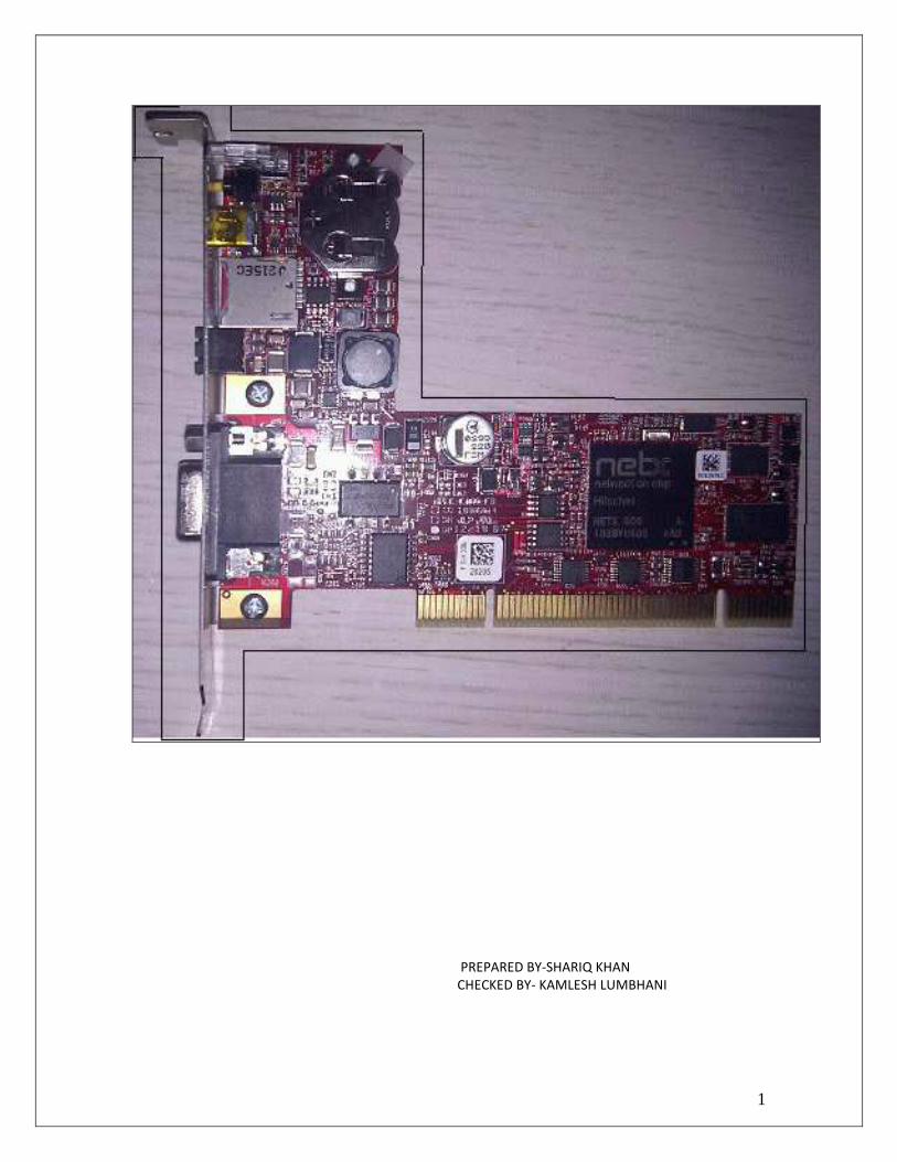
Hilsher netPLC is a concept PLC which can be added to the PC PCI slot and work as Co-Processor along with the CPU. This paper describes communication with SCADA and also provides a brief introduction to PLC and SCADA.TRANSCRIPT
1
PREPARED BY-SHARIQ KHAN
CHECKED BY- KAMLESH LUMBHANI

2
INDEX
1. NetPLC Communication with analog input/output module
1.1. Installation. 01
1.2. Requirement. 01
1.3. System Architecture. 01
1.4. Configuration of CifX Driver. 02
2. Configuration of netPLC in Simatic Manager. 05
2.1 Observation. 19
3 NetPLC communication with CitectSCADA. 20
3.1 OPC server configuration. 22
3.2 OPC client configuration. 29
3.3 Configuration in CitectSCADA 33
3.4 Runtime of CitectSCADA 54
4 References 57

3
ET- 200 M
Profibus DP SLAVE +
AI4/AO2 Module
AI/AO TB
LOOP CALIBRTOR MULTIMETER
NetPLC S7-PCI315
Profibus DP MASTER
Profibus cable
Input: 4-20 mA Output: 0-10 VDC
0.5 sqmm control cable
HILSCHER MAKE NPLC-C100-DP
Profibus Master Device- Hilscher Make S7-PCI315.
Protocol details- Profibus DP Master.
Profibus Slave Device- Siemens Make ET200M (6ES7- 153-2BAO2-OXBO)
Protocol Details- Profibus DP Slave.
1.1 INSTALLATION
1. IBH S7-PCI315.
2. Set up PCI PC Card Device Driver (cifX).
3. S7NetPLCComm Service.
4. IBH OPC server
5. CitectSCADA 7.1
1.2 REQUIREMENTS
1. NetPLC (S7-PCI315).
2. Profibus Interface Module.
3. Profibus cable.
4. Analog I/O Module.
1.3 SYSTEM ARCHITECTURE
4
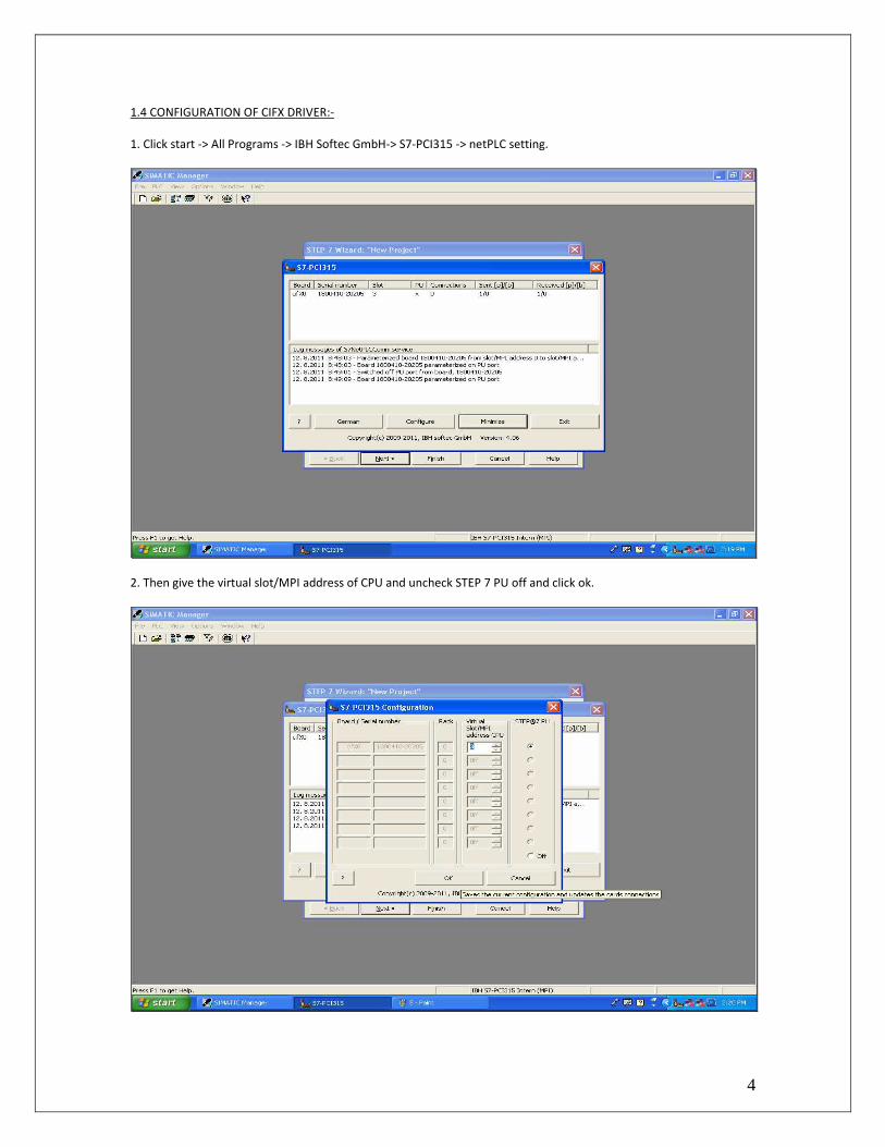
1.4 CONFIGURATION OF CIFX DRIVER:-
1. Click start -> All Programs -> IBH Softec GmbH-> S7-PCI315 -> netPLC setting.
2. Then give the virtual slot/MPI address of CPU and uncheck STEP 7 PU off and click ok.

5
2 CONFIGURATION OF netPLC IN SIMATIC MANAGER
1. Create new project in Simatic Manager Step 7.
2. Go to options menu and select set PG/PC Interface.
6
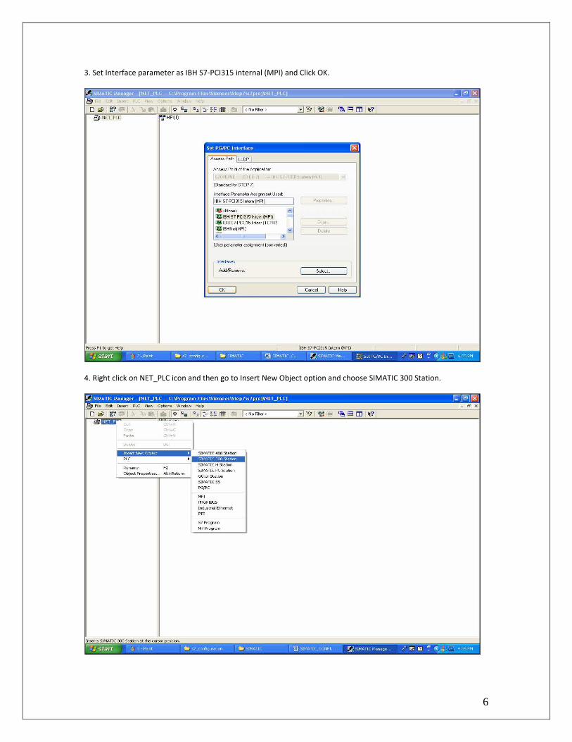
3. Set Interface parameter as IBH S7-PCI315 internal (MPI) and Click OK.
4. Right click on NET_PLC icon and then go to Insert New Object option and choose SIMATIC 300 Station.

7
5. Click on SIMATIC 300(1) Icon.
6. Double Click on Hardware options.

8
7. In the Hardware Configuration first of all insert rail as shown below.
8. Then Insert power supply module in slot no 1 of rail as shown below.

9
9. Then Click on CPU-300 Option and select CPU 315-2DP option as shown below.
10. After selecting CPU 315-2DP then in the Popup window assign the Profibus Interface address and then click on the
new option of subnet.

10
11. Goto Network Settings tab.
12. Now set the transmission rate as 1.5Mbps and profile as DP.
11
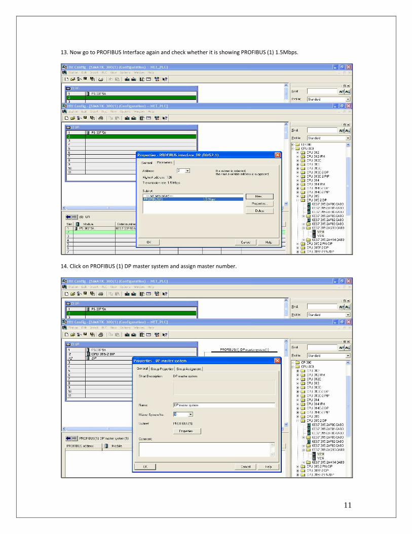
13. Now go to PROFIBUS Interface again and check whether it is showing PROFIBUS (1) 1.5Mbps.
14. Click on PROFIBUS (1) DP master system and assign master number.

12
15. Click on PROFIBUS-DP option from side toolbar of Hardware Configuration and then select ET200M, and further
select IM 153-2.
16. Click ok to Profibus interface IM 153-2.

13
17. The Hardware configuration appears as shown below.
18. Select SM 334 AI4/AI02 8/8 BIT from ET-200M option of AI/AO-300.

14
19. After selecting AI/AO module the configuration of Hardware appears like below.
20. Click on Download option of Hardware Configuration and download the configuration done so far.
15
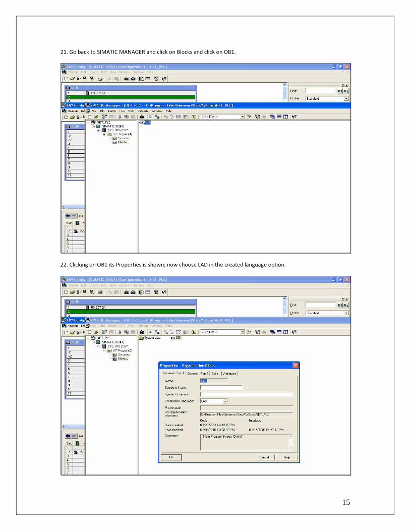
21. Go back to SIMATIC MANAGER and click on Blocks and click on OB1.
22. Clicking on OB1 its Properties is shown; now choose LAD in the created language option.
16
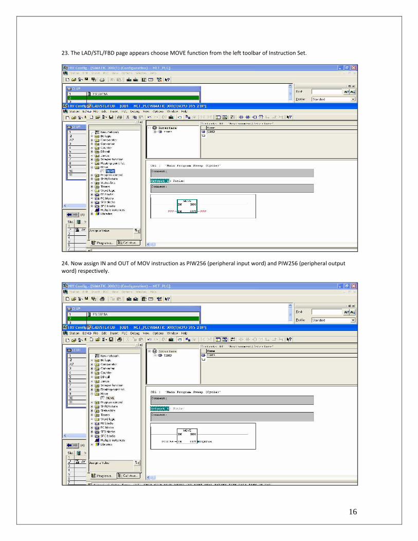
23. The LAD/STL/FBD page appears choose MOVE function from the left toolbar of Instruction Set.
24. Now assign IN and OUT of MOV instruction as PIW256 (peripheral input word) and PIW256 (peripheral output
word) respectively.

17
25. Now download the program from the top toolbar option.
26. Go back to SIMATIC MANAGER page and click on CPU 315-2DP option and click on the PLC option of the top
toolbar and select Copy RAM to ROM option.

18
27. The dialog box shows that the RAM contents were copied successfully to ROM.
19
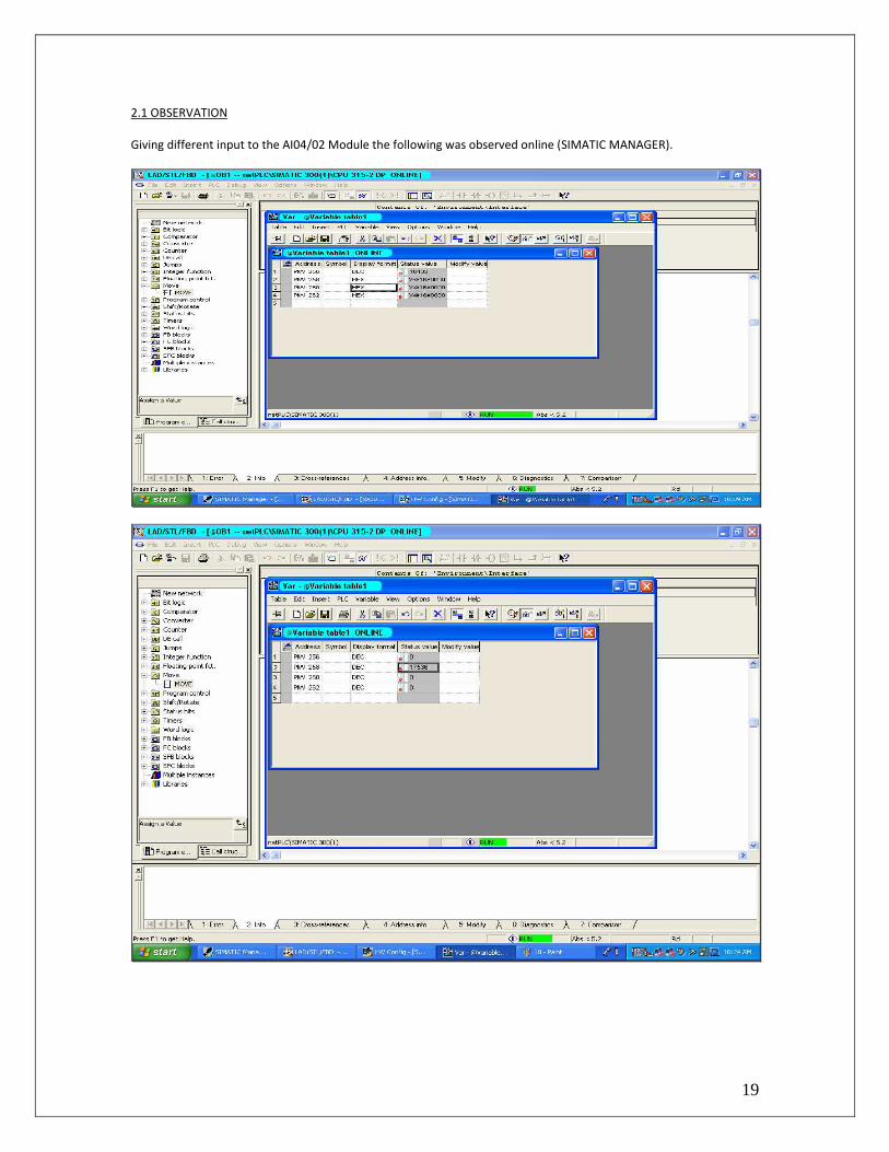
2.1 OBSERVATION
Giving different input to the AI04/02 Module the following was observed online (SIMATIC MANAGER).

20

21
NetPLC COMMUNICATION WITH CITECT SCADA EMPLOYING OPC PROTOCOL

22
3.1 OPC CONFIGURATION
1. Open IBH OPC Editor and create a new file.
2. OPCeditor1 is created then right click on it and insert new PLC.

23
3. Name the PLC as netPLC in PLC properties and choose S7 Simatic Net Protocol.

24
4. Right click on netPLC and define variables.
The following screenshots shows the variable properties.

25

26
5. Now right click on the Generic option in the OPCeditor1 and select variable.

27
6. Right Click on OPCeditor1 and select transfer to OPC server.

28
7. Now choose IBHSoftec.IBHOPC.DA.1 in the select OPC Server option and transfer to server.

29
3.2 OPC CLIENT CONFIGURATION
1. Click on OPC tab option in OPC client and Connect.
2. Select IBHSoftec.IBHOPC.DA.1 in the available server and click ok.
30
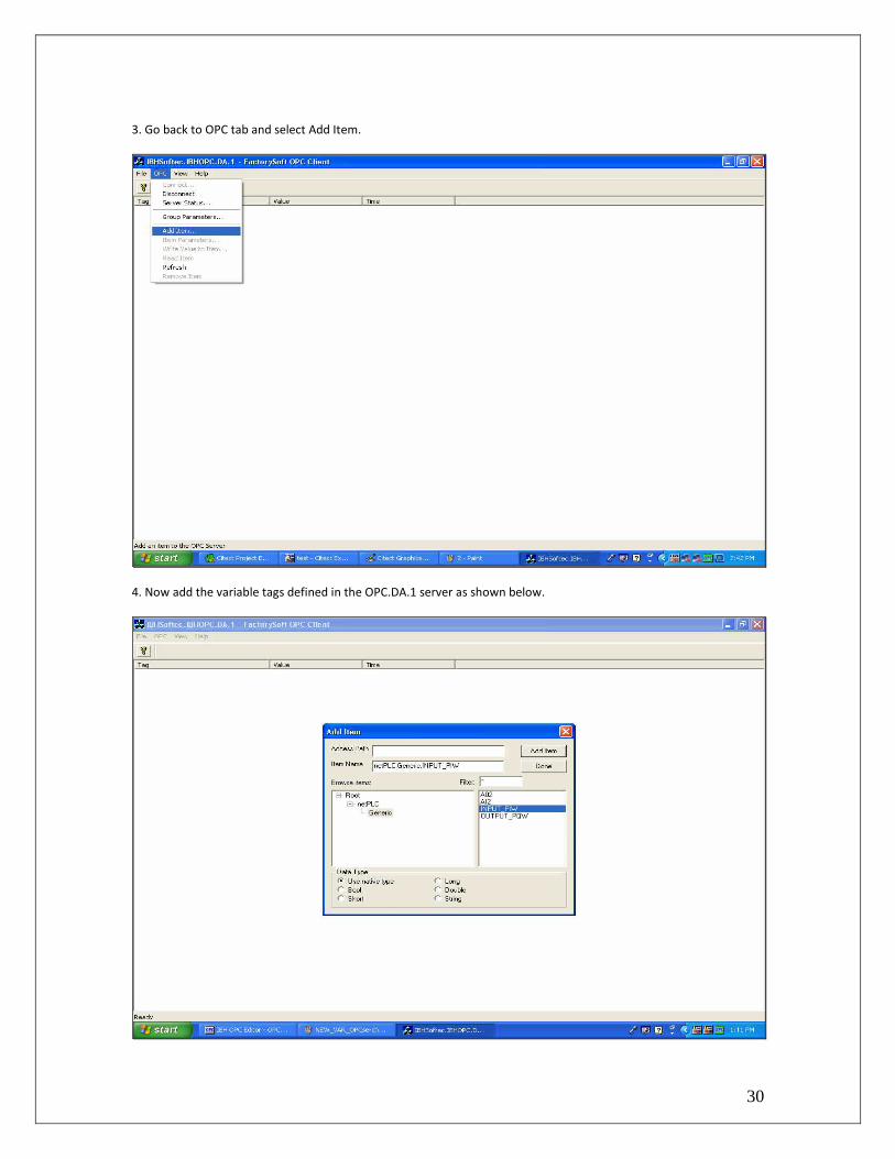
3. Go back to OPC tab and select Add Item.
4. Now add the variable tags defined in the OPC.DA.1 server as shown below.

31

32

33
3.3 CONFIGURATION IN CitectSCADA
1. Goto server option tab in the Citect Project Editor and click select cluster option.
2. Name the c luster and then click add.
34
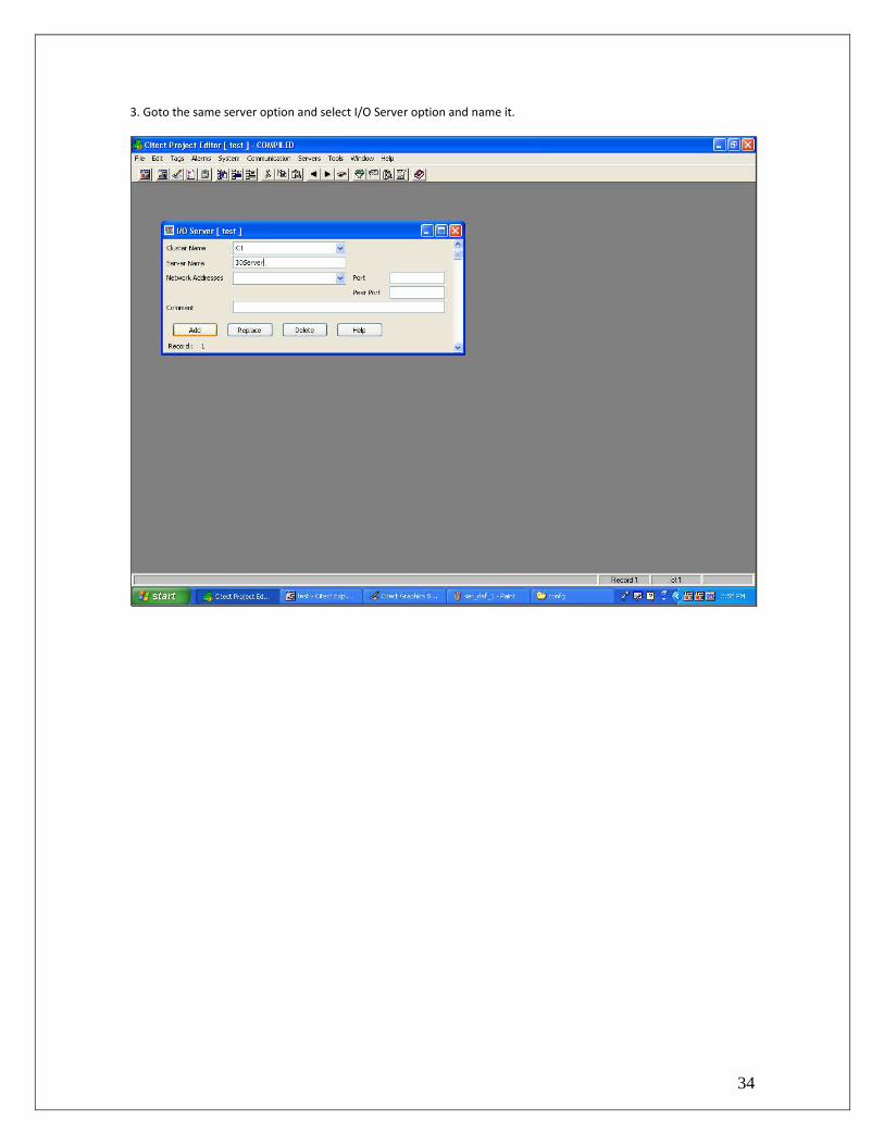
3. Goto the same server option and select I/O Server option and name it.
35
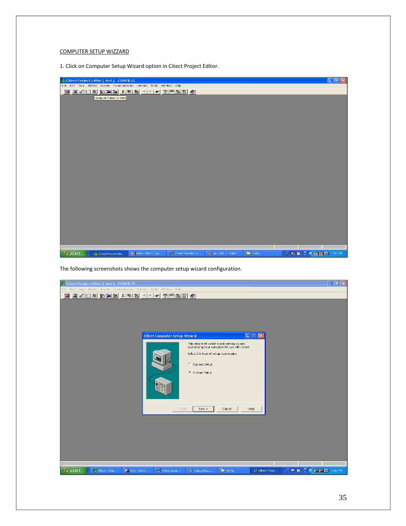
COMPUTER SETUP WIZZARD
1. Click on Computer Setup Wizard option in Citect Project Editor.
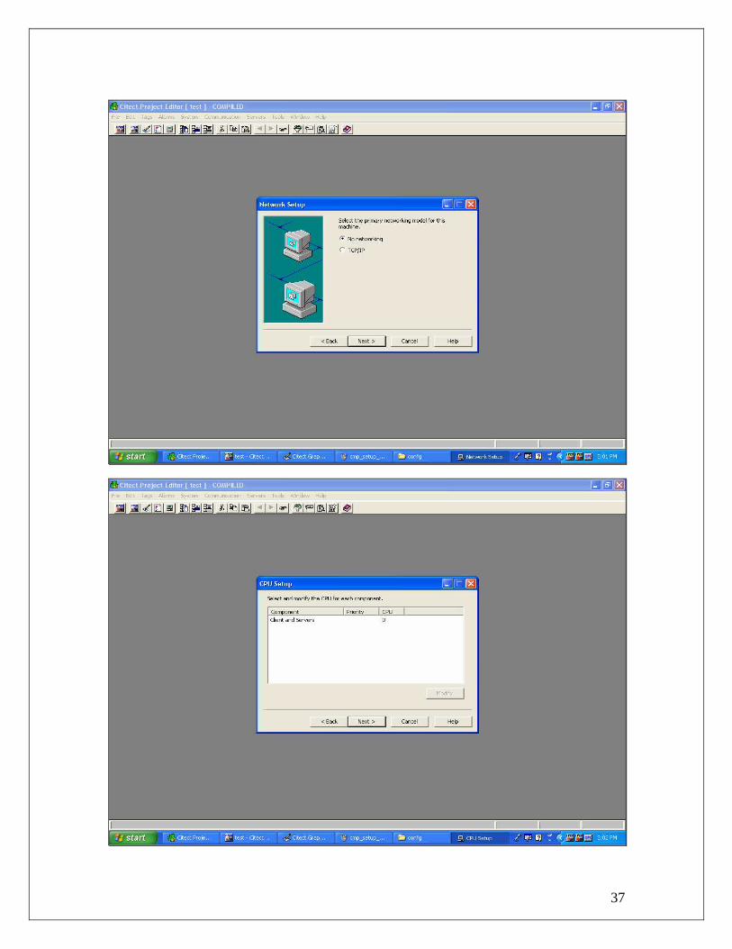
The following screenshots shows the computer setup wizard configuration.

36
37

38

39

40

41
42
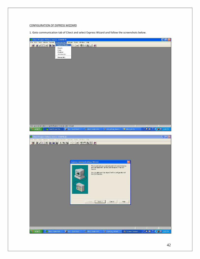
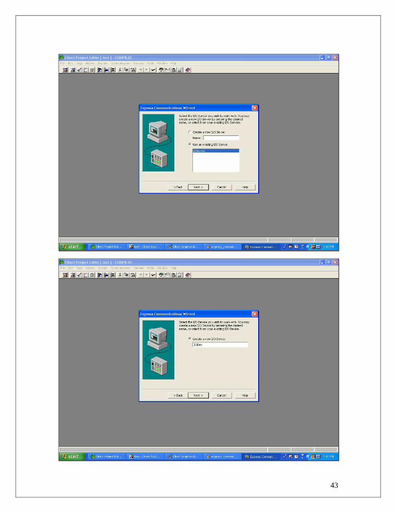
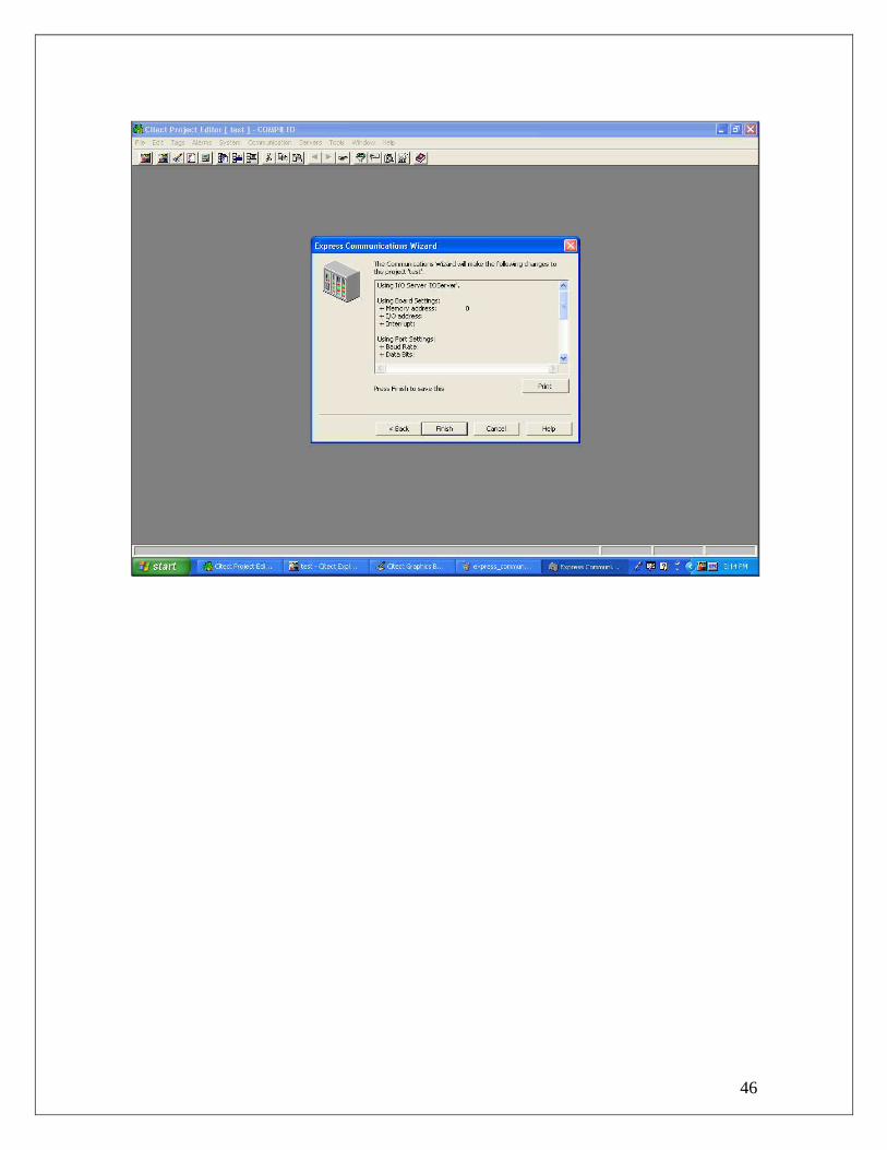
CONFIGURATION OF EXPRESS WIZZARD
1. Goto communication tab of Citect and select Express Wizard and follow the screenshots below.
43

44

45
46

47
CONFIGURING I/O DEVICES, PORTS AND BOARDS
Click on the communication tab of Citect Project Editor and configure I/O devices, Ports and Boards as shown in the
below screenshots.

48
49
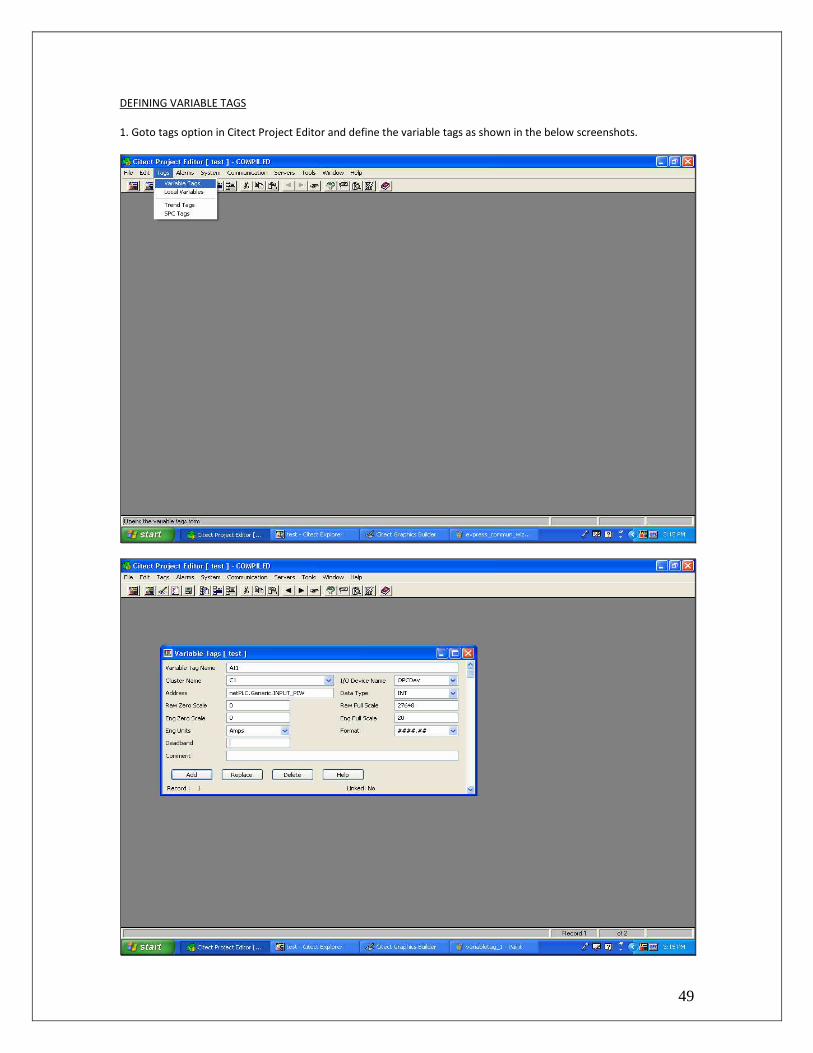
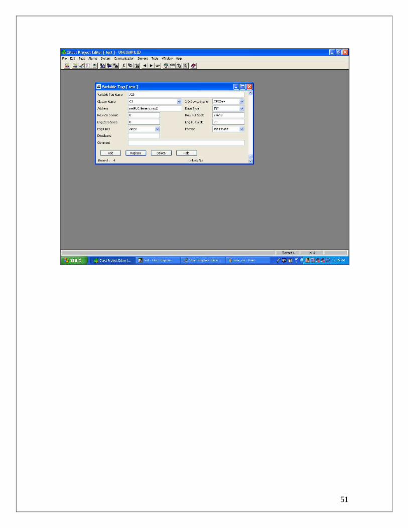
DEFINING VARIABLE TAGS
1. Goto tags option in Citect Project Editor and define the variable tags as shown in the below screenshots.

50
51
52
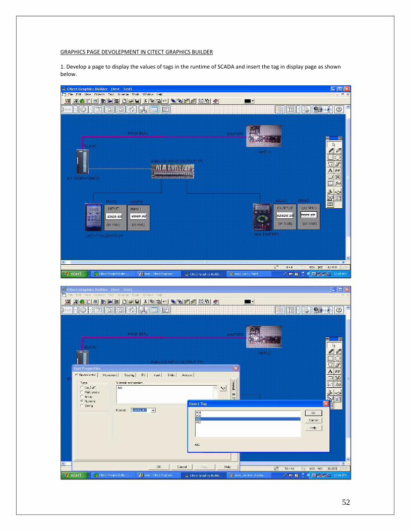
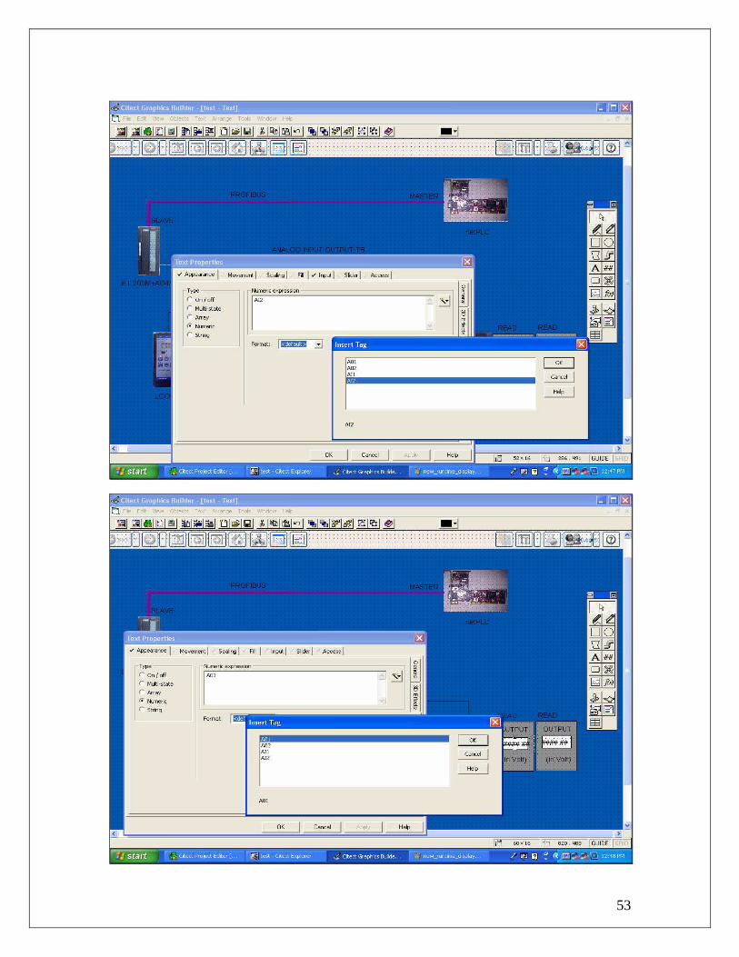
GRAPHICS PAGE DEVOLEPMENT IN CITECT GRAPHICS BUILDER
1. Develop a page to display the values of tags in the runtime of SCADA and insert the tag in display page as shown
below.
53

54
55
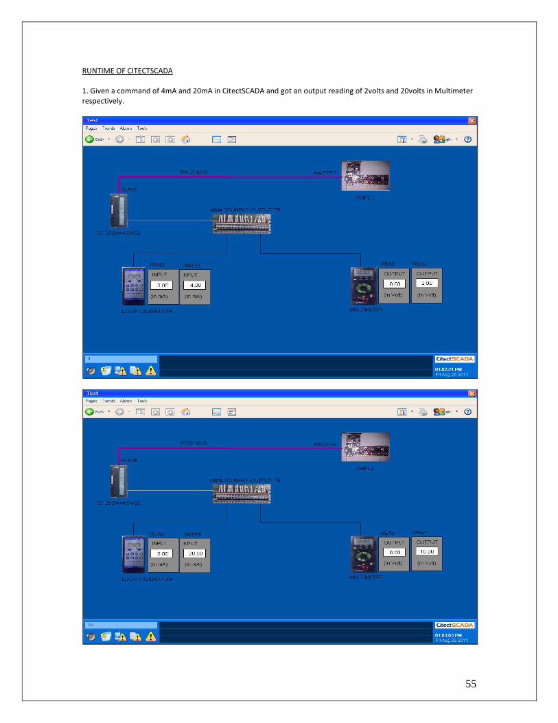
RUNTIME OF CITECTSCADA
1. Given a command of 4mA and 20mA in CitectSCADA and got an output reading of 2volts and 20volts in Multimeter
respectively.

56
2. Provided an input of 4mA and 20mA to the analog input output module and got the following reading in SCADA.

57
4 REFERENCES
1. CitectSCADA Manual 7.0
2. Hilscher website(www.hilscher.com)
3. NetPLC Startup guide.
4. Siemens Catalog.