concepts and experiences for higher plant efficiency with ... · pdf filetodays and future...
TRANSCRIPT

1 Copyright © 2010 by ASME
Proceedings of the 18th Annual North American Waste -to-Energy ConferenceNAWTEC18
May 11-13, 2010, Orlando, Florida, USA
NAWTEC18-3541
CONCEPTS AND EXPERIENCES FOR HIGHER PLANT EFFICIENC Y WITHMODERN ADVANCED BOILER AND INCINERATION TECHNOLOGY
Armin Main, M.Sc. TU, P.E.
FISIA BABCOCK ENVIRONMENT (FBE) GmbHFabrikstrasse 1, D-51643 Gummersbach,
GERMANY
Thomas Maghon, M.Sc. TH, P.E.
FISIA BABCOCK ENVIRONMENT (FBE) GmbHFabrikstrasse 1, D-51643 Gummersbach,
GERMANY
ABSTRACTThe efforts for reducing CO2 Emissions into atmosphere andincreasing costs for fossil fuels concepts are the drivers forEnergy from Waste (EfW) facilities with higher plant efficiency.In the past steam parameters for EfW were requested mainly at40 bars and 400 °C (580 psi and 752 F). In case of coal firedpower plants at the same location as the EfW facilities highersteam parameters at 90 bar, 520 °C (1305 psi, 968 F) have beenused for the design of stoker and boiler. This long-termexperience with higher steam parameters is the platform for thetodays and future demand in higher plant efficiency.Increase in EfW plant efficiency is achievable by increasingtemperature and pressure of live steam going along withoptimized combustion conditions when using well proven gratetechnology for waste incineration. On the other hand highersteam parameters result in higher corrosion rates on the boilertubes and the optimization of the combustion conditions arelimited by the burn out quality requirements of slag and fluegas. Advantages and disadvantages have therefore to bebalanced carefully.This paper will present different measures for optimized boilerand combustion conditions compared to an EfW plant with livesteam at 40 bars and 400 °C (580 psi and 752 F) and 60%excess of combustion air. Plants operated at these conditionshave very low maintenance costs created by corrosion of boilertubes and show performance with very high availability.The following parameters and experiences will be evaluated:- reduction of excess air- flue gas temperature at boiler outlet- higher steam parameters (pressure and temperature)
- heating surfaces for steam superheating in the radiationboiler section
- steam reheating- external superheaters using auxiliary fuels
The comparison of the different methods for increasing theefficiency together with resulting technology challengesincorporates the experiences from modern EfW referencefacilities built in Naples/Italy, Ruedersdorf (Berlin)/Germanyand Heringen/Germany.
Keywords: thermal treatment, Energy from Waste (EfW),boiler efficiency, electrical power output, CO2 reduction
1. INTRODUCTIONIn the existing EfW facilities around the world steamparameters at 40 bars and 400 °C (580 psi and 752 F) are mostcommon and established as inlet parameters for a condensingtype turbine together with steam condensation in an air cooledcondenser. Corrosion on heating surfaces in direct contact withflue gases is undiscernible for EfW boilers operated with thesesteam parameters.The corrosion potential in function of flue gas and heatexchanger tube surface temperature is illustrated in Figure 1 [1].
A distance to all corrosion risk areas is clearly visible for 40bars and 400 °C (580 psi and 752 F).
2 Copyright © 2010 by ASME
Figure 1- corrosion diagram [1]
As a base line for further comparison a facility is defined (basicsolution) with the following design parameters:
- live steam conditions from boiler to turbine inlet : 40 barsand 400 °C (580 psi and 752 F)
- steam pressure at turbine outlet : 0,1 bar (1,45 psi)- boiler feed water temperature 130°C (266 F)- flue gas temperature at boiler outlet : 190 °C (374 F)- furnace excess air : 60%- lower calorific value (LCV): 11 MJ/kg (4725 BTU/lb)- Semi-dry flue gas cleaning system (FGC)
The boiler efficiency according to EN 12952, part 15 [2] forthese basic conditions is 86,5% relating to LCV and 26,35 %for the gross power production.In the following a view is taken on higher electrical efficiencyof EfW plants. With examples from plants build recently anoptimization potential can be identified in relation to the basicsolution.
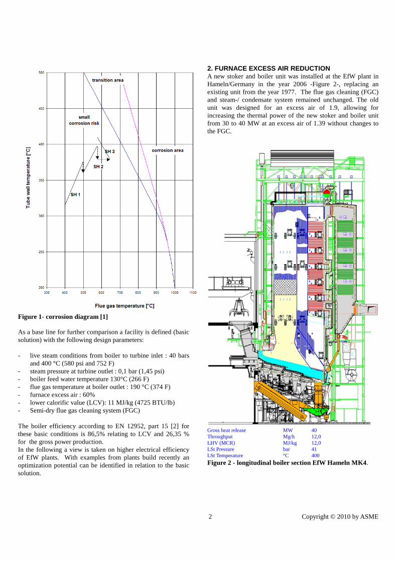
2. FURNACE EXCESS AIR REDUCTIONA new stoker and boiler unit was installed at the EfW plant inHameln/Germany in the year 2006 -Figure 2-, replacing anexisting unit from the year 1977. The flue gas cleaning (FGC)and steam-/ condensate system remained unchanged. The oldunit was designed for an excess air of 1.9, allowing forincreasing the thermal power of the new stoker and boiler unitfrom 30 to 40 MW at an excess air of 1.39 without changes tothe FGC.
Gross heat release MW 40Throughput Mg/h 12,0LHV (MCR) MJ/kg 12,0LSt Pressure bar 41LSt Temperature °C 400
Figure 2 - longitudinal boiler section EfW Hameln MK4.

3 Copyright © 2010 by ASME
The flue gas temperatures in the furnace and after burning zonewere adjusted by means of flue gas recirculation to assure thatthere is no slagging of the membrane walls.Furnace membrane walls and after burning zone are protectedwith SiC plates against corrosion. Inconel 625 cladding is usedin the zone directly above the stoker and on the membrane wallsin the first boiler pass above the refractory lining for a height of5m (16 ft). Other areas of the membrane walls are unprotected.The stoker unit consists of a two track forward moving stokersystem type ‘Steinmueller’ each track with five independentzones over the stoker length and two integrated steps. Goodburn-out of the flue gases and CO-Emission less than 20mg/Nm³ related to dry flue gas condition were achieved withstaged supply of secondary air and 10% recirculated flue gas,taken from behind the electrostatic precipitator.Since start-up of operation until present day significantcorrosion could not be observed in the furnace and the radiationboiler passes neither on protected nor unprotected membranewalls.All superheater surfaces are arranged in the 3rd vertical passand cleaned with steam operated soot blowers. Corrosion orerosion could not be discovered on boiler tubes in superheater 2and 3 directly exposed to the soot blowers due to protectionwith tube shield elements.Compared to the base solution the boiler efficiency is raised to87,65% and gross power production to 26,63 % by furnaceexcess air reduction to 1,39.
3.TEMPERATURE OPTIMISATION AT BOILER OUTLETA substantial enhancement in boiler efficiency can be achievedwith lowering the boiler outlet temperature compared to thebase solution. This available heat at boiler outlet can be usedfor primary and/or secondary air preheating.
Figure 3 – schematic of EfW plant Arhus/Denmark withexternal heat exchangers.
Such a concept was realized in the new build line 4 inArhus/Denmark (Figure 3). The flue gas temperature at boileroutlet is 180°C (356 F) at 100% load (design point DP) beforeentering a baghouse filter.
After this dedusting stage an external economizer is used forfurther flue gas cooling to 140°C (284 F) at a boiler feed watertemperature of 130°C (266 F). The design of this externaleconomizer for dedusted flue gas is compact compared toeconomizers located inside boiler.Next is a further cooling step down to 100 °C (212 F). This fluegas heat exchanger has an enamel tube surface and PFA-foilprotection. The heat from the flue gas is transferred to a coolingcycle, which is in addition taking the heat from the stoker barscooling system. This PFA foil covered heat exchanger isregularly water cleaned to prevent ammonia salts from theSNCR from condensation and settling. The washing water isused as additional water in the FGC scrubber. This re-gainedheat from the flue gas is used in the process for primary andsecondary air preheating.Temperature optimization at boiler outlet to 100°C compared tothe base solution increased the boiler efficiency to 92,63% andgross power production to 28,14 %.The EfW plant Arhus/Denmark is in operation since beginningof 2005. Noteworthy corrosion could not be detected. Thewhole furnace and after burning zone in the 1st boiler pass isprotected with Inconel 625 cladding. After five years ofoperation there was no need for repair works on the claddingdue to wear and tear.
4. EXTERNAL SUPERHEATER A further variant to increase the electrical efficiency of thewhole plant is the superheating of live steam from 400 °C (752F) to 520 °C (968 F) in an external superheater using oil, gas orbiomass. The corrosion risk for the superheater tubes is in thiscase comparable to the base solution as the final superheater isnot in contact with flue gases from the EfW plant.
Gross heat release MW 58,3Throughput Mg/h 17,5LHV (MCR) MJ/kg 12,0LSt Pressure bar 81LSt Temperature °C 520
Figure 4 – longitudinal boiler section EfW plantHeringen/Germany
All temperatures in°C and F
70 158 103 217
150 302
175347
90194 115 239
107 225
82180

4 Copyright © 2010 by ASME
The new EfW plant Heringen/Germany (Figure 4) consisting oftwo units with 58 MW thermal power for pre-sorted trash andan external superheating from 400 °C (752 F) to 520 °C (968F), started operation in 2009. The selection of the steamtemperature 520 °C (968 F) of the new units with existing gas-fired boilers, steam turbine island and boiler feed water systemwas made due to the existing site conditions.The units are designed for 12 MJ/kg (5155 BTU/lb) LCV and athroughput of 17,5 t/h of normal household, commercial andindustrial trash. The stoker is a two track system with watercooling for the first three of total five zones. Realized is aconventional 4 pass boiler with superheaters and economizersin horizontal arrangement. The external superheaters, Figure 5,consisting of a bottom fired natural gas boiler with natural draftare located in direct collateral position to the boiler.
Figure 5 – external superheater EfW plantHeringen/Germany
The superheaters are designed for flue gas temperatures ofapprox. 1000°C (1832 F) as radiation surfaces for the finalsuperheating and the following as conventional bundle heatsurfaces. The flue gas is cooled down to approx. 150 °C (302 F)in the economizers before it is leaving via stack.
Figure 6 – heat flow diagram- EfW plantHeringen/Germany
Figure 6 presents the related heat flow diagram.The temperature control principle for live steam is not asconventional by attemperators; it is done by load control of thenatural gas burner. Already in start-up phase a control of +/- 4 Kat steam turbine inlet was proven without any limitation.The External superheater variant at similar conditions as thebase solution has a boiler efficiency of 87,65% and a grosspower production of 29,68 %.
5. HIGH STEAM PARAMETERSThe new EfW plant in Naples/Italy (figure 7) is in operationsince beginning 2009 and has three lines with 113,3 MWthermal power each. The boilers are designed for high steamparameters of 500 °C (932 F) at 90 bar (1305 psi).
Gross heat release MW 113Throughput Mg/h 27,1LHV (MCR) MJ/kg 15,1LSt Pressure bar 90LSt Temperature °C 500
Figure 7 – longitudinal boiler section EfW plantNaples/Italy
The boiler concept is a vertical boiler with final superheatingstage by platen-type superheaters, arranged in the second boilerpass. The superheaters are located in a flue gas temperaturezone above 800 °C (1472 F). This position could not beavoided as more than 50% of the total heat transferred from theflue gases is needed for the economizer and superheater heat

5 Copyright © 2010 by ASME
surfaces. A boiler according to the base solution (40 bars and400 °C (580 psi and 752 F)) transfers only 37% of the total heatthrough the economizer and superheater heat surfaces. Theremaining heat is transferred through the evaporator heatsurfaces in the radiation passes.It is evident from Figure 8, that for the platen-type superheatersat flue gas temperatures above 800 °C (1472 F) withoutadditional corrosion protective measures high abrasion bycorrosion can be expected.
Figure 8 – corrosion diagram - EfW plant Naples/Italy
This is in conformity with experiences from other plants buildby the predecessor companies of FBE in the seventies andeighties. Those plants operated with steam temperature of 500°C (932 F) achieve 5.000 - 8.000 h of superheater life time.For longer lifetimes these superheaters were protected withmonolithic SiC concrete. This system has been used in theStuttgart/Germany EfW-plant with success. 10 years ofsuperheater lifetime could be achieved with those protectedsuperheaters. This long lifetime could only be shown under theprecondition of regular inspection and direct repair of cracksbefore the tube itself shows corrosion attacks.Tests in various plants have shown in the past, that Inconelcladding as corrosion protection for platen-type superheaters is
not recommendable. High tube surface temperatures areresponsible for high abrasion of Inconel cladding.
Figure 9a – platen superheaters EfW plant Naples/Italy, transport to site
A first inspection of all three boilers in the Naples EfW facilityin November 2009 (Figure 9a and 9b) has shown a good statusof the monolithic SiC concrete protection of the platen-typesuperheaters.
Figure 9b – platen superheaters EfW plant Naples/Italy, status November 2009
We expect a similar inspection and maintenance effort as in theStuttgart EfW plant. For these higher steam parameters there isno change in boiler efficiency of 86,5%, but gross powerproduction is climbing to 30,2 %.
6. BOILER WITH INTERMEDIATE REHEATThe intermediate reheat concept was chosen for theRuedersdorf (Berlin)/Germany EfW plant for high electricalefficiency. This intermediate reheat is shown in figure 10.The heat surfaces for final superheater and intermediate super-heater need to be positioned (analog to Naples) in the secondboiler pass as the heat taken by the economizer and superheaterheat surfaces is higher than 50% of the total heat transferredfrom the flue gases. The platen-type superheaters of theRuedersdorf (Berlin)/Germany EfW plant illustrated in figure

6 Copyright © 2010 by ASME
11 are protected by Inconel 625 cladding as wear plating. Asteam temperature of 420 °C (788 F) allows this protectionconcept in contrast to the Naples EfW plant with 500 °C (932F).
Figure 10 – heat schematic Ruedersdorf (Berlin)/GermanyEfW plant
Gross heat release MW 110Throughput Mg/h 27,3LHV (MCR) MJ/kg 14,5LSt Pressure bar 90LSt Temperature °C 420Reheat Pressure bar 24,4Reheat Temperature °C 420/273
Figure 11 – longitudinal boiler section Ruedersdorf(Berlin)/Germany EfW plant
In the temperature zone up to approx. 850 °C (1562 F) flue gastemperature and 420°C (788 F) steam temperature the materialInconel 625 may be serviceable. The Ruedersdorf
(Berlin)/Germany EfW plant is in operation since middle 2008.Regular checks have been done with encouraging results so far.For a long term experience further operating hours need to becollected. Platen-type superheater with Inconel 625 cladding aswear protection instead of castable protection can be cleanedwith pneumatic rappers. The construction of platen-typesuperheaters is shown in Figure 12a and 12b.
Figure 12 a – platen-type superheater
Figure 12 b – platen-type superheater with rapping system
Commissioning of a turbine island with intermediate reheatrequires more complexity. Steam blowing for pipe cleaning hasto be done over various ways for- boiler high pressure part till high pressure turbine- connecting tubes to the outlet of the high pressure turbine- intermediate heat exchanger till inlet of the second turbine
stageAfter these measures the steam turbine with intermediatereheating could be taken safely into operation.For intermediate reheat there is no change in boiler efficiency of86,5%, but gross power production is grown to 29,9 %.

7 Copyright © 2010 by ASME
7. COMPARISON OF BOILER CONCEPTSThe results in efficiency of EFW-plants and the related grosspower production are shown in table 1.The calculations were made on unified conditions for:(1) trash composition (as the base solution)(2) turbine outlet pressure(3) feed water temperature(4) turbine isentropic efficiency(5) condensate pre-heatingas well as further parameters for the water/-steam cycle.
Table 1 – Comparison Base solution and Variants 1-5
The overall assessment of various stoker & boiler systemsolutions has to include - beside the energetic efficiency- thefollowing aspects:
• operating performance• availability• costs for consumables• investment and maintenance
Table 2 – Comparison Base solution and Variants 1-5
Table 2 evaluates these criteria for each variant. The ratingsystem-relative to the base solution and non-numeric-points outthe impact or tendency of the variants for those criteria.
CONCLUSIONS
For the different variants presented, the following conclusionsca be drawn:
Furnace excess air reduction (Variant 1)The reduction in excess air should – depending on thecombustion system – be done as far as possible in order toreduce the flue gas loss of the boiler. The membrane walls ofthe after burning zone should be protected with Inconel 625 oras shown for the Hameln/Germany EfW plant concept, withreduced flue gas temperature by recirculation.The reduction in excess air is equally possible for Variant 2-5with similar effect and equivalent efficiency optimization.
Temperature optimization and additional flue gas cooling(Variant 2)The type of flue gas system dictates the opportunities of thisvariant. In case of a semi-dry FGC system heat used forevaporation of lime milk cannot be recovered. When a flue gasheat exchanger is installed for cooling down the flue gases, ithas to be cleaned during operation and washing water becaptured. Compared to the base solution this variant is a goodalternative without constraints to plant operation andmaintenance costs. The investment in additional heat exchangersurfaces is offset to extra earnings in generated electric power.A combination with variant 3, 4 and 5 is possible withoutlimitation for increase in efficiency.
External superheater (Variant 3)This variant requires approx. 14,5% of the thermal power fromtrash in addition from an auxiliary fuel as gas, oil or biomass.The additional fuel represents an important part of the plantoperation costs. Compared to the base solution there are noconstraints to plant operation, maintenance costs andavailability. The tube wall temperature of the membrane is dueto higher pressure compared to the base solution approx. 50 Khigher and the 1st pass has to be protected with Inconel 625.
High steam parameters (Variant 4)Higher power output of this variant goes along with loweravailability due to higher inspection and maintenancerequirements for the platen-type superheaters.Higher steam pressure compared to the base solution is causingthe necessity for additional Inconel cladding in the 1st pass.
Intermediate reheat (Variant 5)Characteristic for the intermediate reheat variant is a very highelectric power output. It is an interesting solution withoutmonolithic SiC concrete superheater protection necessity. Provehas to be provided for the lifetime of cladded platen-type
Basis Var. 1 Var. 2 Var. 3 Var. 4 Var. 5
Change compared to Basis ReducedExcess Air
Fluegas cooler
ExternalSuper-heating
HighSteamparam.
SteamReheating
Electrical Power Production 0 0 to + + ++ ++ ++
Costs for Consumables 0 0 0 - - 0 0
Life Time of Membranwalls1st Pass without add. Corrosion
Protection0 0 to - 0 - - -
Life Time of Superheaters 0 0 0 0 - -
Cost for Investment 0 0 to + 0 to - 0 to - 0 to - -
Maintenance Costs 0 0 0 0 - 0 to -
Availability 0 0 0 0 - 0 to -
Continuous Operation Period 0 0 0 0 - 0
Legend : 0 comparable; + positive; ++ very positive; - negative; - - very negative
Basis Var. 1 Var. 2 Var. 3 Var. 4 Var. 5
change compared to basisReduced
Excess Air
Flue gas cooler
External Super-heating
High Steam param.
Steam Reheating
Temperature Live Steam °C 400 400 400 520 500 420
Pressure Live Steam Bar 40 40 40 90 90 90
Temperature Reheated Steam
°C - - - - - 420
Pressure Reheated Steam Bar - - - - - 24
Flue Gas Temp. Boiler Outlet
°C 190 190 100 190 190 190
Excess Air % 60 39 60 60 60 60
Boiler Efficiency % 86,5 87,7 92,6 87,0 86,5 86,5
Boiler Efficiency related to Basis
% 100 101,3 107 100,5 100 100
Gross Electrical Efficiency % 26,4 26,6 28,1 29,7 30,2 29,9
Gross Electrical Efficiency related to Basis
% 100 101,1 106,8 112,6 114,6 113,3

8 Copyright © 2010 by ASME
superheaters. In case of evidence for sufficient long lifetimeonly the investment costs for cladded heat surfaces and theintermediate reheat compared to the base solution balanceagainst a higher income in electric power sales. Availability anduninterrupted operation time we expect not to vary from thebase solution.
Combination of Variants
The combination of the variants presented is leading to higherefficiencies as the single variant. On the other hand drawbacksneed to be accepted for each advantage of individual variantsand their multiple combinations.General tendencies were shown starting from a base solution -with fixed parameters - for the purpose of comparison only toshow the impact of the different variants. Higher boiler feedwater temperatures and lower steam outlet pressures canincrease the gross power production up to 30%.Assessment of all advantages and disadvantages for eachindividual case is necessary to find an optimum solution.
REFERENCES[1] J. Kümmel, 1994, “Dampfkessel in Hausmüll- undRestmüllverbrennungsanlagen“, VDI Bildungswerk Feuerungs-, Verbrennungs-., Vergasungstechniken, Düsseldorf Februar1994[2] EN 12952-15, 2003, “Water tube boilers and auxiliaryinstallations Part15: Acceptance tests; European Standard, 2003