conceptual database design - datu bāzes tehnoloģijas · 2017-02-08 · conceptual database design...
TRANSCRIPT

Conceptual Database Design
Conceptual Database Design
Table of Contents
1 Terminology.......................................................................................................... 2 2 Universal Relation Approach.............................................................................. 4 3 Entity-Relationship Model .................................................................................. 8
3.1 ER Model (Entity) ............................................................................................ 8 3.2 ER Model (Relationship)................................................................................ 10 3.3 ER Model (Constraints).................................................................................. 11 3.4 ER Model (Keys)............................................................................................ 14 3.5 Mapping ER diagrams.................................................................................... 16
4 Database Design with UML............................................................................... 19 4.1 UML Class Diagrams..................................................................................... 19 4.2 UML Associations.......................................................................................... 21

Conceptual Database Design
1 Terminology
Data Engineering: Phases
Three Phases of Database Design
• Conceptual Design (DBMS Independent)
• Logical Design (Transactions Independent).
• Physical Design (Schema for a particular DBMS and particular set of transactions)
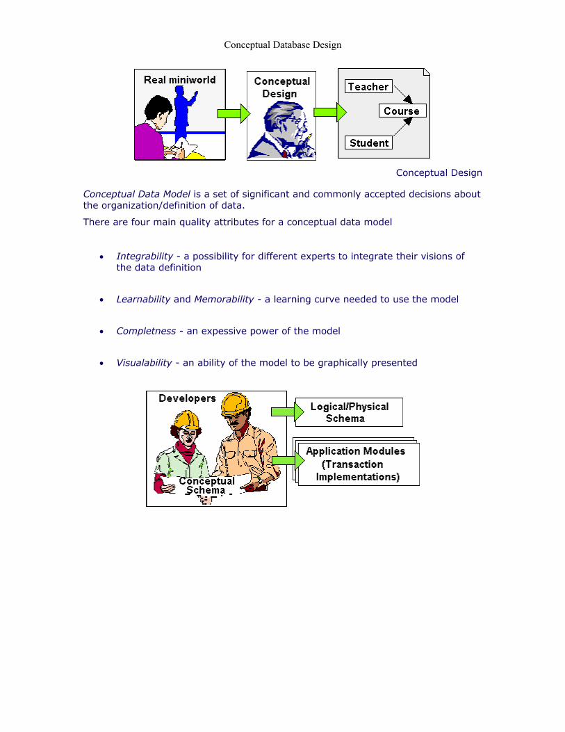
Conceptual Design
Conceptual design is a kind of Requirements Analysis. Conceptual design is based on a special Conceptual Data Model. that captures the semantics of information stored in a database.
Thus, goal of the Conceptual Design:
• Identify Data Objects (Entities)
• Identify all attributes of the Data Objects
• Identify Relationships between Data Objects
• Identify Integrity Constraints
Conceptual Database Design
Conceptual Design
Conceptual Data Model is a set of significant and commonly accepted decisions about the organization/definition of data.
There are four main quality attributes for a conceptual data model
• Integrability - a possibility for different experts to integrate their visions of
the data definition
• Learnability and Memorability - a learning curve needed to use the model
• Completness - an expessive power of the model
• Visualability - an ability of the model to be graphically presented

Conceptual Database Design
2 Universal Relation Approach
Universal Relation Approach
Universal Relation Approach is entirely based on relational normalization technique. Please recollect that there exist so-called functional dependencies between domains.
A determinant is an attribute or a set of non-redundant attributes which can act as a unique identifier of another attribute (or another set of attributes) of a given relation.
Formally speaking, A is a deteminant of B (A B) if a particular value of A (say, A1) determines a particular value of B (say, B1).
For example,
• C# is a determinant of Cname, Ccity and Cphone [C# (Cname, Ccity, Cphone)]
• (C#, P#, Date) is a determinant of Qnt [(C#, P#, Date ) Qnt]
Universal Relation Approach
Generally speaking, we can identify all domains (attributes) of a certain application first. For example, we can see a list of attributes as follows: C#, Cname, Ccity, Cphone, P#, Pname, Price, Date and Qnt
Now we can define a single relation on all these domains.
Such relation defined on all domains identifyed for a particular application, is called a Universal Relation.

Conceptual Database Design
Universal Relation Approach
In a similar way, we can try to identify all functional dependencies between attributes. Suppose, we identified a set of non-redundant, full functional dependencies as follows:
C# (Cname, Ccity, Cphone) P# (Pname, Price) (C#, P#, Date) Qnt
Universal Relation Approach
Now, we can split (normalize) the universal relation to produce a set of relations in 3rd normal form. Attributes are identifyed by a primary key, by the whole primary key, by nothing but the primary key.
C# (Cname, Ccity, Cphone) - Relation "Customer" P# (Pname, Price) - Relation "Product" (C#, P#, Date) Qnt - Relation "Transaction"
Universal Relation Approach
When using the Universal Relation model approach to database design, one possible approach is to follow the major steps that are listed below:

Conceptual Database Design
• Study the description of the application.
• Identify all attributes (domains) that are of interest to the application.
• Identify functional dependencies that are of interest to the application.
• Process all the functional dependencies to identify set of non-redundant, full dependencies.
• Split universal relation into a number of application relations in 3rd normal form.
• Check that the schema (resultant relations) conforms to the description of the application.
It should be noted that database design is an iterative process.
Universal Relation Approach
The universal relational model has a number of very serious drawbacks:
• Insufficient expressive power
For example, how to express a situation when E#(Employee Number) defines D#(Department number) where the employee works, and D# defines E# of its head
E# D# (Works for a department) D# E# (Department has a head)
• Naming Conventions
Since, many different experts are normally participate in the conceptual design, they should easily communicate their results. How, for example, we can assure that all experts use notation E# for an employee number.

Conceptual Database Design
• Graphical presentation of the model
Notation like " E# D# " is not easy to understand and communicate to other experts without additional explanations.

Conceptual Database Design
3 Entity-Relationship Model
Entity-Relationship Model
Entity-Relationship (ER) model is a conceptual model based on the perception of a real world that consists of
• a set of objects called entities and attributes of the entities
• relationships among those objects
• constraints imposed on the entities and relationships
3.1 ER Model (Entity)
Entities
An entity instance, or entity occurrence, is a "thing" or an "object" in the real world that is distinguishable from other objects.
• Each entity occurrence is presented as a number of attributes.
• Each attribute has a domain (i.e. name of the attribute) .
• Domains specify the set of permitted values for attributes.
Entities
An entity type is a set of similar entity occurrences. The term "similar" can be perceived as "presenting with different values of the same domains".
Since, the model operates with entity types, we will refer to an "entity type" as simply to an "entity".

Conceptual Database Design
Pragmatically, we will understand the term "entity" as a description of common properties of a set of entity occurrences.
Entities
Entity-Relationship (ER) diagram is a graphical notation for the Entity-Relationship model.
Entities are represented as rectangulars, attributes are represented by ellipses in ER diagrams.
• A customer is an entity
• All customers have attributes such as C# ("customer number") and Cname ("customer name")
• There can be as many as needed such customers
• A product is an entity
• All products have attributes such as P# ("product number") and Pname ("product title")
• There can be as many as needed such products
Conceptual Database Design
3.2 ER Model (Relationship)
Relationships
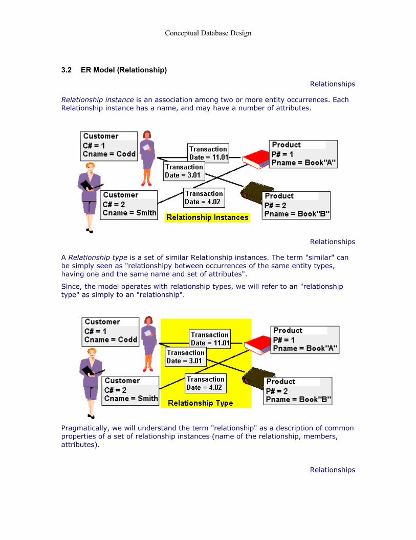
Relationship instance is an association among two or more entity occurrences. Each Relationship instance has a name, and may have a number of attributes.
Relationships
A Relationship type is a set of similar Relationship instances. The term "similar" can be simply seen as "relationshipy between occurrences of the same entity types, having one and the same name and set of attributes".
Since, the model operates with relationship types, we will refer to an "relationship type" as simply to an "relationship".
Pragmatically, we will understand the term "relationship" as a description of common properties of a set of relationship instances (name of the relationship, members, attributes).
Relationships

Conceptual Database Design
Relationships are represented as diamonds, attributes of a relationship are represented by ellipses in ER diagrams.
• A transaction is a relationship
• The "Transaction" relationship is an association among occurrences of "Customer" and "Product"
• All "Transaction" relationships have an attribute such as date ("date of transaction")
• There can be as many as needed such "Transaction" relationships
3.3 ER Model (Constraints)
Cardinality Constraints
Cardinality constraints express the number of entitiy occurrences to which another entity occurrence (other entity occurrences) can be associated via a relationship instance.

Conceptual Database Design
In a simplest case (one-to-one relationship), only one occurrence of one type can be associated with exactly one occurrence of another type by means of one instance of the relationship.
Cardinality Constraints
In more complex cases, a certain occurrence of one type can be associated with a set of occurrences of another type by means of one instance of the relationship.

Conceptual Database Design
The diagram above allows one particular customer to buy more than one product by means of a single transaction.
Cardinality Constraints
We can also imagine a so-called "many-to-many" relationship between entity occurrences.
The diagram above allows any number of cutomers to buy any number of products by means of a single transaction.
Participation Constraints
Consider the following ER Diagram:
A current state of the information model may well look as follows.
Conceptual Database Design
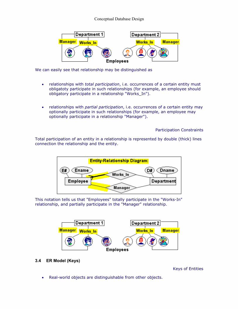
We can easily see that relationship may be distinguished as
• relationships with total participation, i.e. occurrences of a certain entity must
obligatoty participate in such relationships (for example, an employee should obligatory participate in a relationship "Works_In").
• relationships with partial participation, i.e. occurrences of a certain entity may optionally participate in such relationships (for example, an employee may optionally participate in a relationship "Manager").
Participation Constraints
Total participation of an entity in a relationship is represented by double (thick) lines connection the relationship and the entity.
This notation tells us that "Employees" totally participate in the "Works-In" relationship, and partially participate in the "Manager" relationship.
3.4 ER Model (Keys)
Keys of Entities
• Real-world objects are distinguishable from other objects.

Conceptual Database Design
• An entity is presented in database using a set of attributes.
• Hence, each entity has a key (a non-redundant set of attributes that uniquelly identifies an entity occurrence).
Primary keys of entities are underlined in an ER diagram.
This notation tells us that each "Employee" is identified by its number (E#), and each "Department" is identified by his/her number (D#).
Weak Entity
Some entities can be identified uniquelly only by considering another (owner) entity.
Suppose, for example, that a number of an employee is unique only for a particular department.
In this case, we need to define the "Employee" key as a composition of department number (D#) and emloyee number (E#) within the department.
Such entities are called weak entities.
Identifying Relationship
A weak entity can inherit attributes from another (owner) entity providing the following preconditions are fullfilled.

Conceptual Database Design
• Owner entity (e.q. "Department") and the weak entity (e.q. "Employee") participates in a "one-to-many" relationship (e.q. "Works_In")
• The weak entity (e.q. "Employee") has total participation in this identifying relationship.
Note that identifying relationships are drawn in sick lines.
3.5 Mapping ER diagrams
Mapping ER diagrams
Normally, mapping ER diagrams into relational database schemas is rather stright forward process.
• Entities are presented as realational database tables
CREATE TABLE Department( D# INTEGER, Dname CHAR(25), PRIMARY KEY (D#))
CREATE TABLE Employee( E# INTEGER, Ename CHAR(25), PRIMARY KEY (E#))
Mapping ER diagrams
• Relationships are also presented as realational database tables having corresponding foreign keys and attributes.

Conceptual Database Design
CREATE TABLE Department(D# INTEGER, Dname CHAR(25),PRIMARY KEY (D#)) CREATE TABLE Employee(E# INTEGER, Ename CHAR(25),PRIMARY KEY (E#))
CREATE TABLE Works_In( E# INTEGER, Position CHAR(25), D# INTEGER, PRIMARY KEY (E#), FOREIGN KEY(D#) REFERENCES Department )
Mapping ER diagrams
• In a simple case of one-to-one or one-to-many relationships without attributes, they can be mapped as additional foreign keys in tables corresponding to entityes.
CREATE TABLE Department( D# INTEGER, Dname CHAR(25), E# INTEGER, PRIMARY KEY (D#), FOREIGN KEY(E#) REFERENCES Employee )
CREATE TABLE Employee( E# INTEGER, Ename CHAR(25), D# INTEGER, PRIMARY KEY (E#), FOREIGN KEY(D#) REFERENCES Department )
Mapping ER diagrams
• Constraints are normally modelled as associated procedures that are invoked whenever a tuple(object) is added/deleted or modifyed

Conceptual Database Design
CREATE TABLE Employee( E# INTEGER, Ename CHAR(25), D# INTEGER, PRIMARY KEY (E#), FOREIGN KEY(D#) REFERENCES Department, ON DELETE checkParticipationConstraints(), ON ADD checkCardinalityConstraints() )
Majour Steps in E-R Design
When using the E-R model approach to database design, one possible approach is to follow the major steps that are listed below:
• Study the description of the application.
• Identify entity sets that are of interest to the application.
• Identify relationship sets that are of interest to the application.
• Identify value sets and attributes for the entities and the relationships.
• Determine cardinality and participation constraints.
• Identify primary keys for entities.
• Check that ER diagram conforms to the description of the application.
• Translate the ER diagram to the database schema for a selected DBMS.
It should be noted that database design is an iterative process.

Conceptual Database Design
4 Database Design with UML
Database Design with UML
Any software project must be specified, visualized, and documented in a way that meets requirements of all experts involved in the design and development.
Such equally understandable specififacions can be implemented only by means of a commonly accepted notation. UML (Univarsal Modelling Language) provides such notation.
UML defines twelve types of diagrams, divided into three categories:
• Four diagram types (Structural Diagrams) represent static application structure; (Class Diagram, Object Diagram, Component Diagram, Deployment Diagram).
• Five diagram types (Behavior Diagrams) represent different aspects of dynamic behavior; (Use Case Diagram, Sequence Diagram, Activity Diagram, Collaboration Diagram, Statechart Diagram)
• Three diagram types (Model Management Diagrams) represent ways you can organize and manage your application modules; (Packages Diagram, Subsystems Diagram, Models Diagram)
4.1 UML Class Diagrams
Objects
UML follows to object-oriented design principles. It present a real world in a form of objects. An object is a "thing" or an "event" in the real world that is distinguishable from other objects.
• Each object is presented as a number of attributes.
• Each attribute has a domain (i.e. name of the attribute) .
• Domains specify the set of permitted values for attributes.

Conceptual Database Design
You can see that the term "object" is almost identical to the term "entity occurrence" used in E-R design.
Classes
Objects are created as instances of a particular class. We can also say that a data class is a set of similar objects. The term "similar" can be perceived as "presenting with different values of the same domains".
Again, you can see that the term "class" is almost identical to the term "entity" used in the E-R design.
The only difference that we should note is assigning a scope to attributes
• local attributes ( - ) are internal for instances of the class, they may have duplicate names, and cannot be used as foreign keys to refer to such instances;
• global attributes ( + ) may not have duplicate names within the database, and can be used as foreign keys to refer to instances of this data class;
Methods
Another important Object-Oriented Design concept is assigning methods (operations) to all instances of a particular class.

Conceptual Database Design
When we use UML for a database design, we suppose that all the classes support the following methods:
• tuple: get() returns an instance of this class. We can see it as reading of a tuple.
• void: modify(tuple) replaces all the object attributes with new values.
We will see that these defauld methods can be overriden and extended.
4.2 UML Associations
Associations
UML is able to represent two types of associations between data objects (instances of data classes):
Aggregation is a bi-directional relationship between instances of two data classes.
Aggregation is represented by a diamond.
Aggregation is a bidirectional association containing references in both directions. For example, a customer contains references to all of products bought by the cutomer. At the same time, any product contains references to all customers who bought it. Similarly, a customer contains reference to his/her bank account, and any a bank account contains a reference to its owner.

Conceptual Database Design
Associations
Cardinality constraints are presented with integers and asterisks near the association.
For example, the asterisk near the products represents many instances and the 1 near the customer represents just one instance that can participate in the aggregation.
Thus, there is a one to many relationship between customer and product.
Stereotypes
UML includes a notation called stereotypes and they can be found on all diagrams. Stereotypes are displayed as text inside a " << ... >>" bracket. i.e. <<Manager>>. Stereotypes were invented by the designers of UML as a way to give different UML shapes more specialized roles to describe a diagram component.
An example of a stereotype we can show how to distinguish between associations having different meaning.
In this particular case, we distinguish between two different associations which might be set between instances of departments and employees.

Conceptual Database Design
Navigability
If a relationship exists in only one direction, it ia called Navigability . Aggregation is represented by an arrow directed to the class which instances do not contain references to instances of the second class.
A customer may have bought many products and contains references to all of such products. Products do not contain references to corresponding customers.
Navigability
Analogically, the following diagram says that:
Each project contains references to all employees involved in it, employee does not contain references to projects in which he/she is involved.
Each department contains a reference to its manager. The manager (employee) does not contain additional references to department except the reference ("Works-In") common for all employees.
Navigability

Conceptual Database Design
It should be especially noted that UML aggregations often provide an ambiguous view onto a database project.
Thus, using navigability associations is more preferable for such projects.