conceptual design review - core.ac.uk · musculoskeletal disorder (msd). according to the european...
TRANSCRIPT
Exoskeleton: Prototype design
Conceptual design review
Oscar Teruel Guisado
Degree Thesis for Bachelor of Engineering
Degree Program in Energy and Environmental Engineering
Vaasa (Finland), April 2016

BACHELOR’S THESIS
Author: Oscar Teruel Guisado
Degree Program: Energy and Environmental Engineering
Supervisor: Lars Enström
Title: Exoskeleton: Prototype Design – Conceptual Design Review
____________________________________________________________________________
Date 22/04/2016 Number of pages 55 Appendices 3
____________________________________________________________________________
Abstract
The design projected in this document has features specifications of an exoskeleton structure
with loads operation finality. The entire structure is divided into three major parts: the lower
body, the chest, and the arms. Each part was considered separately, and all of the parts can be
assembled together to create the main structure.
In this document are collected all the corresponding designs of each element that will
compound the final prototype. The lower body represents the base of the structure and
supports, the weight of the other two parts and the advance, allowing them to move backwards
as well as allowing rotational movement. The chest serves the purpose of a user cabin, where
the operator will be placed to operate the exoskeleton. The purpose of the arms is to raise and
carry loads.
Although some parts of the study could not be completed due to time constraints, the
exoskeleton has been designed for a real use. A user is needed to drive the structure and for
this reason an anthropometrical study was completed in order to adapt the design to a real
situation.

The electrical design and the control system needed for the prototype functionality are not
considered in this project. These sections could be studied at a later time by another person or
team as a future complementary study for this project.
As it is a prototype design, this project does not consider any law or design legislation.
Additionally, no health and security study was done.
_________________________________________________________________________
Language: English Key words: Exoskeleton, mechanical, design.
_________________________________________________________________________

Table of contents
1 Introduction ............................................................................................. 1
2 Definitions ................................................................................................ 3
3 Design requirements ............................................................................... 5
3.1 Anthropometric study.......................................................................................................... 5
3.1.1 Introduction ................................................................................................................. 5
3.1.2 Data used ..................................................................................................................... 5
3.2 Interface definition .............................................................................................................. 7
3.3 General dimensions ............................................................................................................. 8
3.3.1 Preliminary arm dimensioning...................................................................................... 8
3.3.2 Preliminary dimensioning of the shoulder-back set. ................................................... 12
3.3.3 Lower body preliminary dimensions ........................................................................... 19
3.4 Movement range ............................................................................................................... 21
3.4.1 Shoulder movement................................................................................................... 21
3.4.2 Elbow movement ....................................................................................................... 23
3.4.3 Hip movement ........................................................................................................... 24
3.5 Global dimensioning .......................................................................................................... 25
3.6 Components unification..................................................................................................... 26
4 Design evolution .................................................................................... 27
4.1 Common elements in the design ........................................................................................ 27
4.1.1 Wheels....................................................................................................................... 27
4.1.2 Actuator..................................................................................................................... 27
4.1.3 Vertical profile, lineal guides and subjection plate ...................................................... 30
4.1.4 Engine and engine bearing/Battery ............................................................................ 33
4.2 Subassemblies ................................................................................................................... 34
4.3 Chest ................................................................................................................................. 38

4.3.1 Arms .......................................................................................................................... 40
4.3.2 Material ..................................................................................................................... 42
4.3.3 Box ............................................................................................................................ 43
4.3.4 Maximum height that the load could be raised .......................................................... 45
4.3.5 Ideal transporting position ......................................................................................... 45
4.3.6 Manoeuvrability ......................................................................................................... 46
4.3.7 Exoskeleton storage ................................................................................................... 50
4.4 Final design........................................................................................................................ 51
5 Budget .................................................................................................... 51
6 Conclusion ............................................................................................. 54
7 Literature references............................................................................. 55

Appendix Table of Contents
Annex 1 – Analytical calculations
Annex 2 – Catalogues
Annex 3 – Construction drawings

1
1 Introduction
The objective of this study is to create a Conceptual Design Review (CDR) of an
exoskeleton. The study includes an anthropometrical study and the design and mechanical
functionality of the structure. It is an open project aimed to be improved and finished later.
These following points will not be considered:
Electrical and electronic installation needed for operation.
Control and automation system that would allow for correct operation.
As this is a conceptual design, security and health risks are not taken into account.
As a mechanical engineering student, one of my wishes is to be able to create a machine
from only one concept, and if it is possible, to make it capable of improving society, The
reason for completing this project, is to address a current problem in society:
Musculoskeletal disorder (MSD).
According to the European Agency for Safety and Health at Work:
Musculoskeletal disorder is most common professional disease in the EU-27, 25%
of European workers complain about back pain and 24% affirm to have muscular
pain.
63% of EU-27 workers are exposed during one quarter part or more of their time to
repetitive movements of the hands and arms, 47% are exposed to painful or
extenuating postures and 33% are required to transport or move heavy loads.
Agriculture and construction are the sectors with the most workers exposed to
physical risk and affected by MSD. However, all sectors are affected by it to some
extent.
MSD is an expensive affliction due to direct costs (insurance, compensation,
medical and administrative cost) and indirect costs due to loss in productivity.
The lifting of medium and heavy weight loads is a problem for a lot of workers in different
works and companies. Hundreds of kilograms of loads are transported by pallet lifters or

2
electric lift trucks, but some loads are too small to be carried by machines but also too
heavy to be loaded by people.
This exoskeleton has potential for use with this rank of loads, being a machine able to carry
loads of zero to fifty kilograms. These are the loads that are commonly carried by people
and can contribute to development of MSD.
Some examples of situations in which the exoskeleton could be useful include:
Product unloading and transport in agriculture and cattle-raising sectors.
Baggage transport between an airport’s conveyor belts and aircraft loading.
Transportation and loading of packages in a post office.
Necessary software
The following software will be used for the calculations and design of the prototype:
Microsoft Office Excel
SolidWorks
Microsoft Office Excel is a spreadsheet software that will be used for the analytic
calculations of the needed parameters to check the validity of the design. These parameters
will be represented in tables. This allows the data to be displayed in a visual and intuitive
way that facilitates comprehension.
SolidWorks is three-dimensional design software that includes tools for creating,
simulating, publishing and administrating data in a simple and functional interface.

3
2 Definitions
Exoskeleton
In biology the term “exoskeleton” is used to describe the outer rigid structure of an insect or
crustacean. In the robotic field, exoskeletons are the external rigid structures that give
support to the people motor functions. Exoskeletons include a motor power system that
gives part of the energy to the limb movement, and helps the user to move and realize
activities, such as carrying weight.
An exoskeleton can be defined therefore as an external structural mechanism whose
segments and joints correspond to the human body. It allows direct transmission of the
mechanical power and information signals. Therefore, it must be adjustable or adaptable to
different human body joints, with the objective of aligning the rotational centers.
Special aspects as security, robustness and the robotic mechanism ability should be
considered.
Mechanical structure
An exorobot or exoskeleton is formed by a series of linked elements joined by articulations
that allow relative movement. There are three different kinds of joints: translational,
rotational and mixed.
Each of the independent movement that an articulation can make with respect to the above
is called a degree of freedom. The sum of the robot’s articulation degrees of freedom is the
total number of degrees of freedom of the entire robot.
Actuators
Actuators are responsible for generating movement of the elements that forms the
exoskeleton. In robotics, an actuator’s classification is based on its power source:

4
pneumatic, electrical or hydraulic. Table 1 displays a summary of differences in the basic
characteristics of actuator types:
Table 1: Different actuator characteristics.
Actuator type Advantages Disadvantages
Pneumatic
Low cost
Fast
Simple
Robustness
It requires a special installation
Noisy
Hydraulic
Fast
High load capacity
Stability against static charges
It requires a special installation
Difficult maintenance
Expensive
Electrical
Precise and trustable
Noiseless
Easy control
Easy installation
Restricted power
The selection of the actuator will depend upon the following factors: cost, velocity, control,
power, precision, weight, volume, maintenance and security.
Biomechanics
Biomechanics is the scientific discipline that studies existing mechanical structures,
fundamentally from the human body.
The study of biomechanical is present in different spheres, but three of them are currently
the most important.
- Medical biomechanics
- Sport biomechanics
- Occupational biomechanics

5
3 Design requirements
The following section details the design requirements that the exoskeleton must fulfill.
3.1 Anthropometric study
3.1.1 Introduction
After specifying the exoskeleton’s general aspects and its various parts, the necessary
measurements of the arm elements will be determined.
First, it must be considered that the machine designed will be used by a person. It is
essential to have anthropometric studies where the dimensions of the elements are clearly
defined, and movement limitations are imposed. The exoskeleton must fit the human body
in order to guarantee commodity and security to the user.
3.1.2 Data used
The exoskeleton should be able to be used for different physical and height size. In the pre-
design stage different anthropometric data were used to delimitate the movement range and
the dimensions of its elements.
The digital magazine “Elfdeportes” has collected a total of 29 anthropometric variables
into a table (figure 1). These variables are defined through statistical techniques. The table
shows, for each variable, a range of values that were taken into account when the
dimensions of the machine were delimited.

6
Figure 1: Anthropometrical characteristics table (measurements in cm) / Source: “Elfdeportes”

7
Figure 2: Bidimensional representation for measurements identification / Source: “Elfdeportes”
According to the previous table, the total and partial dimensions of each element were
estimated. In an analog way, they were taken into account to define some movement
ranges, such as the Top and Bottom Death Centers (TDC and BDC) in the bending actions.
3.2 Interface definition
The exoskeleton is divided in three subassemblies: arms, chest and lower body. These
subassemblies were studied individually because each part has a dynamic movement with
respect to the others. The joining elements that allow the dynamic movement are called
interfaces.
Two different interfaces could be found in the final structure:
- Exoskeleton: Chest-arms
- Exoskeleton: Chest-Lower body

8
3.3 General dimensions
3.3.1 Preliminary arm dimensioning
The initial values for the arm design were established in accordance with “Manual de
Antropometria Normal Patológica”.
Figure 3: Dimensions used in the arm design / Source: Manual de Antropometria Normal Patológica.
Arm length (distance shoulder-elbow)
It was designed to be used by the majority of the population. Thus, the design considered
the extremes to be negligible, with the 5th
percentile for women as the minimum and the
95th percentile for man as the maximum (Figure 1).
The following table presents the values mentioned:
Table 2: Anthropometrical arm length measurements
B, Arm length
Age Woman Man
16 years 5% 50% 95% 5% 50% 95%
27,9 cm 30,4 cm 33,4 cm 29,5 cm 32,9 cm 36,1 cm
Finally, the dimensional range will be between 27,9 cm and 36,1 cm.
9
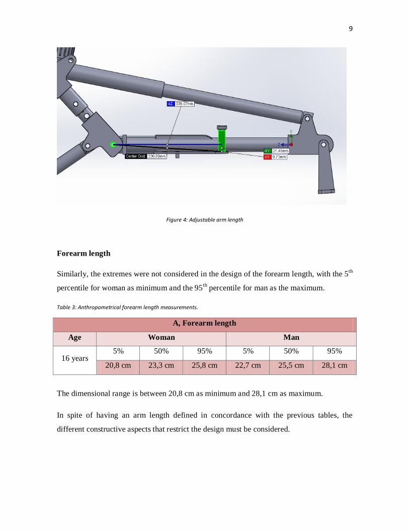
Figure 4: Adjustable arm length
Forearm length
Similarly, the extremes were not considered in the design of the forearm length, with the 5th
percentile for woman as minimum and the 95th
percentile for man as the maximum.
Table 3: Anthropometrical forearm length measurements.
A, Forearm length
Age Woman Man
16 years 5% 50% 95% 5% 50% 95%
20,8 cm 23,3 cm 25,8 cm 22,7 cm 25,5 cm 28,1 cm
The dimensional range is between 20,8 cm as minimum and 28,1 cm as maximum.
In spite of having an arm length defined in concordance with the previous tables, the
different constructive aspects that restrict the design must be considered.

10
In the case of the arm, the minimum measurement has been changed to 30 cm to account
actuator installation conditions. Meanwhile, the maximum measurement of the forearm has
been changed to 25 cm.
It must be taken into account that the real mechanical forearm is much longer than the user
human forearm, because it needs more longitude to pick the load. Therefore it is enough to
set this length to 25 cm. The next table adds the anthropometrical design values.
Table 4: Anthropometrical design measurements for the arm and the forearm
Anthropometrical design values
Minimum dimension Maximum dimension
Shoulder-elbow length, B 30 cm 35 cm
Elbow-wrist length, A 20 cm 25 cm
Figure 5: Adjustable forearm length

11
Consequently, the majority of the population is represented by this specified set of values.
The different parts of the mechanical arm will be dimensioned in such a way that the length
of the elements can be regulated between these dimensions to adapt to the user.
In accordance with the aforementioned, the mechanical forearm must be bigger than the
user’s in order to reach the loads. The following table collects the final arm dimensions of
the exoskeleton.
Table 5: Dimensional range of the entire arm
Measurement type Minimum value Maximum value
Arm length (from shoulder axis to the “shovel” fixation point) 95 cm 100 cm
In conclusion, the different arm positions are:
Table 6: Different lengths for the different arm positions.
Position number Biacromial width
Position 1 95 cm
Position 2 97,5 cm
Position 3 100 cm
Figure 6: Total adjustable arm length

12
3.3.2 Preliminary dimensioning of the shoulder-back set.
The measurements that were useful to determine the general dimensions are as follows..
Biacromial distance (between deltoids)
The chest width dimensions were defined using the anthropometrical measurements for the
population found in the book “Manual de Antropometria Normal Patológica”.
The attached table shows the biacromial back width values for men and women of 19 years
old in different percentiles.
Table 7: Biacromial distance for both sexes
Biacromial distance
Age Women Men
19 years 3% 50% 97% 3% 50% 97%
34,1 cm 37,2 cm 40,4 cm 36,3 cm 40 cm 43,5 cm
The minimum biacromial distance is 34,1 cm while the maximum one is 43,5 cm.
These measurements do not include the deltoids distance, because it was impossible to find
information regarding this, a distance was assumed. The minimum and maximum assumed
distances are displayed in the following table.
Table 8: Biacromial distance of the machine
Measurement type Minimum value Maximum value
Final shoulder distance 60 cm 77 cm
The biacromial distance must be adjustable. In detail, it was decided that the back width
will vary by 6 cm. The following table shows the final shoulder distances for each position.

13
Table 9: Adjustable position with biacromial distance.
Position numbers Shoulder width
Position 1 60 cm
Position 2 66 cm
Position 3 72 cm
Position 4 78 cm
Figure 7: Adjustable shoulder length
Back height (seat-shoulders)
In this case, the digital magazine “Elfdeportes” was used again to obtain the ranges and to
establish the minimum and maximum values.
As in the previous section, the minimum value corresponds to the 5th percentile for women
and the maximum corresponds to the 95th
percentile for men.
The following table shows the back height values taken for men and women in different
percentiles.

14
Figure 8: Maximum and minimum distance between seat and shoulders / Source: Elfdeportes
Having these values as a reference and bearing in mind the physical limitation for the
exoskeleton design (interferences with other pieces) the final dimension for the back are as
follows:
Table 10: Dimensional range for the back height
Measurements type Minimum value Maximum value
Back height 45 cm 65 cm
These values are the nominal measurements from the metallic seat base to the middle
reference shoulder point. Around 2-5 cm corresponding to the padded final part width of
the seat have to be added to these measurements. This is not an exact measurement,
because it depends on the chosen material for this function.
Figure 9: Adjustable back height

15
Seat dimensioning
The aim of the seat is to provide commodity and the ergonomics for the user in the work
place. The anthropometric measurements taken as reference are presented in the following
table.
Figure 10: Main distances for a sitting position person./Source: “Mueblesdomoticos” website
Figure 11: Anthropometrical dimension of a sitting person / Source: “Mueblesdomoticos” website
Such as the seat height has to be adaptable to the user, the most important measurement is
the hip width dimension (G parameter in figure 10): 43,4 cm for the 95th women percentile
that represents the most unfavorable situation. For the design, the hip width will be set at 41

16
cm. Such as the seat is designed for human dimensions, these little variations are not
representatives.
The chosen depth is 25 cm. This dimension allows a relative commodity for the backside
support point when the exoskeleton is in the maximum position from the floor.
Figure 12: Final seat dimension
Back support dimensions
The back support in any common seat has to support the lumbar region such as essential
function. The configuration of this has the objective of adapting the spinal profile but it will
avoid the complete coupling that does not allow changing the position of the body.
Considering the previously imposed conditions and the absence of concrete data about the
referent pattern values to follow, the measurements were determined through an
anthropometric study of some known people. These values are shown in the following
figure.
The shown measurements in mm allow a sufficient support for the user, giving enough
comfort and stability sensation. Head support and back support compose a unique piece.
410 mm
17
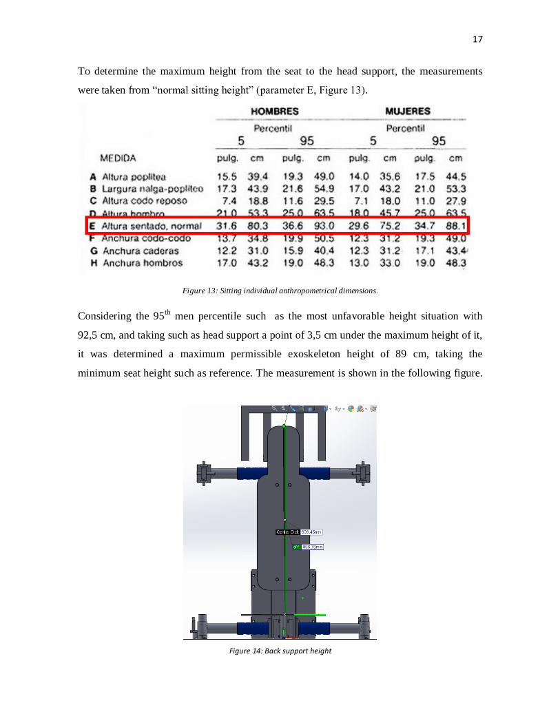
To determine the maximum height from the seat to the head support, the measurements
were taken from “normal sitting height” (parameter E, Figure 13).
Figure 13: Sitting individual anthropometrical dimensions.
Considering the 95th
men percentile such as the most unfavorable height situation with
92,5 cm, and taking such as head support a point of 3,5 cm under the maximum height of it,
it was determined a maximum permissible exoskeleton height of 89 cm, taking the
minimum seat height such as reference. The measurement is shown in the following figure.
Figure 14: Back support height

18
Head security structure dimensioning.
Using the book “Felisberto e Pascuoarelli (2001)” the head security structure dimensions
were established.
Table 11: Human head anthropometrical dimensions.
Seat to head height (04)
Women Men
3% 50% 97% 3% 50% 97%
81,5 cm 87,5 cm 92,5 cm 75,5 cm 82,5 cm 88,5 cm
Head height from chin (23)
Women Men
3% 50% 97% 3% 50% 97%
20,5 cm 22,5 cm 23,5 cm 18,5 cm 21,5 cm 23,5 cm
Head height (24)
Women Men
3% 50% 97% 3% 50% 97%
16,5 cm 17,5 cm 18,5 cm 13,5 cm 14,5 cm 15,5 cm
Head depth (25)
Women Men
3% 50% 97% 3% 50% 97%
17,5 cm 18,5 cm 9,5 cm 15,5 cm 17,5 cm 18,5 cm
Figure 15: General head dimensions/Source: Elfdeportes

19
The measurements used in this section were the head width, height and depth, as well as the
height from it to the seat. Such as this element does not need to be adjustable, the
measurements taken were the most unfavorable; the 95th
men percentile measurements were
the chosen ones.
Figure 16: Security structure dimensions
The head is localized at 93 cm from the seat base, taking into account the most unfavorable
user height (04 measurements from table 11).
3.3.3 Lower body preliminary dimensions
In this case all the data were found in the book “Felisberto e Pascuoarelli (2001)”.
Buttock-knees distance
The distance between the back part of the seat to the footrest must be between 42 cm and
53 cm approximately as is shown in the following table.
Figure 17: Buttock-knees distance / Source: Elfdeportes
Width 19 cm
Depth 20 cm
Height 24 cm

20
Table 12: Buttock-knee dimensional range
Measurement type Minimum value Maximum value
Buttock-knee distance 43 cm 52 cm
Hip width
Bearing in mind the user comfort, ergonomics and functionality, the distance between feet
was also considered. The exoskeleton user will spend almost all the working day with feet
in the same position, so this should be such as comfortable and natural as possible.
For these reasons, it was decided that the ankle, knee and hip will be in the same vertical
plane. For this design the hip width from the book “Felisberto e Pascuoarelli (2001)” was
used.
Figure 18: Hip width dimension for both sexes / Sources: Elfdeportes.
As 30 cm is the 5th
women percentile and 41 cm is the 95th
women percentile, the
measurements range is:
Table 13: Hip width dimensional range
Measurement type Minimum value Maximum value
Hip distance 30 cm 41 cm
To ensure that the entire dimensional specter was completed, it was decided that between
14 cm and 48 cm from the vertical body are the footrest measurements.
The aim is to change the position of the feet during the usage of the machine.

21
Figure 19: Maximum footrest dimension
3.4 Movement range
Once the interfaces are defined, the movement range of the adjustable elements was
delimited. The delimited elements are: shoulder rotation in the horizontal plane, shoulder
rotation in the vertical plane and the rise and decline movement in the squat action.
3.4.1 Shoulder movement
Movement in the horizontal plane
The design is based on the idea that the user should be capable of holding different loads
with different shapes and dimensions. It was defined that the horizontal movement range
would be between -10º to 20º, it is supposed that the 0º is the position where the arm is
perpendicular to the back support.
This angle is conditioned by the ensemble stability and utilization, as the facility to pick up
and discharge any kind of allowed load inside the exoskeleton use limitations.
140 mm
22
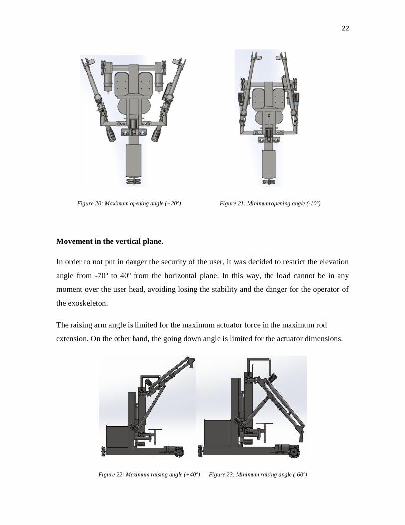
Figure 20: Maximum opening angle (+20º) Figure 21: Minimum opening angle (-10º)
Movement in the vertical plane.
In order to not put in danger the security of the user, it was decided to restrict the elevation
angle from -70º to 40º from the horizontal plane. In this way, the load cannot be in any
moment over the user head, avoiding losing the stability and the danger for the operator of
the exoskeleton.
The raising arm angle is limited for the maximum actuator force in the maximum rod
extension. On the other hand, the going down angle is limited for the actuator dimensions.
Figure 22: Maximum raising angle (+40º) Figure 23: Minimum raising angle (-60º)

23
3.4.2 Elbow movement
Arm flexion angle
The minimum axial angle between the arm and the forearm is limited for the maximum
extension of a human arm and it corresponds to the axial axis alignment. On the other hand,
the maximum angle is restricted by the minimum extension possibility of the actuator.
Table 14: Arm movements’ limitations
Movement limitations
Angle (º)
Arm over the horizontal plane 40
Arm under the horizontal plane -60
Minimum angle (arm 1 – forearm 1) 0
Maximum angle (arm 1 – forearm 1) 90
Maximum opening from vertical plane (arm 1- arm 2) 20
Maximum closing from vertical plane (arm 1- arm 2) -10
Figure 24: Minimum elbow angle Figure 25: Maximum elbow angle

24
3.4.3 Hip movement
Movement limit: squat and stand up.
The action was studied in an empirical way in an average person. In this way, a set of
parameters were obtained for, in an ergonomic and comfort point of view, the user could
realize this action in a functional and satisfactory manner.
The most adequately feet-seat distance was obtained; this is between 42 cm and 53 cm.
Then, it was defined a bottom dead center (BDC), it is the distance between the exoskeleton
base to the seat in its lowest position, 30 cm. The distance from the exoskeleton base to the
footrest is 6 cm, being at the end a total of 37 cm.
On the other hand, it was assumed the distance from the exoskeleton base to the highest
position of the seat, 80 cm, as the top dead center (TDC). Thus these values were
considered enough to realize the movement in a functional way, avoiding the risk that could
create the total extension or articulation of the knee, as it is done in the real life.
Figure 26: Minimum seat height

25
Figure 27: Maximum seat height
3.5 Global dimensioning
Next, it is explained and shown the general exoskeleton dimensioning.
The less compact configuration is when the arms are completely stretched at 40º over the
horizontal plane, the shoulder in its larger position and the seat in its highest configuration
and the highest position is when the arms are completely shrunk, the shoulders in its lowest
position and the seat in its lowest configuration.
Table 15: Extreme exoskeleton dimensions
Case Height Length
Less compact 2151 mm 1591 mm
Most compact 1450mm 990mm

26
Figure 28: Most compressed position Figure 29: Most extended position
3.6 Components unification
With the goal of reducing costs and unify the assembly processes, it was tried that the
similar functional elements had the same design, it is called “Design intention” in the 3D
parametric design world. With that, the maintenance work is easier and the spare stock is
reduced with all the advantages that it involves, like a smaller requirement in warehouse
space.
The following elements were dimensioned with design intention:
- Footrest
- Tubular profiles
- Retractile shoulder structure
- Rotating cylinder
- Demountable ear
- Retractile support structure
- Tubular profile and support hairpin

27
4 Design evolution
4.1 Common elements in the design
4.1.1 Wheels
One of the most important decisions was the wheel election, it should be capable to realize
the progress and reverse movement, as the rotation in both directions.
After comparing different kind of wheels, it was decided that the one that was more useful
for this project is the “omni wheel”.
The main omni wheel advantage in front of the common wheels is the disappearance of the
dragging component. Consequently, the exoskeleton could rotate and advance in any
direction without any restriction. In addition, the machine storage would be better with this
kind of wheels.
It is needed to know how much weight each wheel must bear, all the calculations are shown
in “Annex 1: Analytical calculations”, and the method to choose the wheel in the section
“Final design”.
4.1.2 Actuator
It was needed to decide which kind of device would be chosen to elevate the load and the
weight of the operator.
The first idea was that the seat was rooted in the platform; in this situation the actuator
shouldn’t raise the weight of the user. But, as the objective is that the exoskeleton has to be
able to be driven for different heights people, it means that the seat should be adaptable,
because the user must fit in the exoskeleton to have the shoulders in the correct height to
concordance with the exoskeleton shoulders.
The easiest way to solve that problem is that the shoulders and seat were joined and floating
regarding the platform. With this solution, the user only has to sit and adjust the seat to

28
have the shoulders in the correct position. Then the actuator would move the entire floating
load like a set until the user was in the most comfortable position with their feet in the
footrest.
Hydraulic actuator
It is capable of carrying big load with precision, but in this prototype there is no need to
carry excessive loads, then the disadvantages are bigger than the advantages it offers.
Mainly the needed space for the oil deposit, the actuator dimension and the expensive
maintenance are the reasons why this kind of actuator was not chosen.
Pneumatic actuator
The pneumatic actuator is capable to raise lower loads than the hydraulic actuators, but it
works faster. In this prototype, this high speed is not needed, and it also was not chosen for
the needed installation space that requires this kind of actuator, as the compressor and the
air deposit.
Electrical actuator
The lineal electrical actuator is shown as the best choice for this prototype. It is able to raise
big loads and the energy can be storage in batteries that feed as the wheels engines as the
actuators engines.
Another important fact is the energy cost of each actuator, being the electrical one the most
profitable.
Finally studying all the previous kind of actuators, the chosen one is the electrical actuator
because is the one that fits better in this prototype.

29
With the maximum allowed load, maximum user weight and the exoskeleton arms and back
weights, it can be done the stress force calculation that each actuator will bear. With this
data, it was possible to choose the correct actuator through catalogues. The calculations can
be found in the “Annex 1: Analytical calculations, section 2: Actuator election
calculations”. 3090 N was obtained as the maximum load value, having this force; it was
able to choose the actuator ALI4 24-Vdc. that has a capacity of 4100 N.
Figure 30: ALI4 24-Vdc. / Source: Actuator catalogue.
After contrasting different technologies to get arm movement, it was decided to also choose
a combination of actuators to create the arm movement in the vertical plane. As this
previous actuator can raise all the structure weight plus the load, it is also a good option to
use the same model in the arm subassembly, because the measurements of it fits inside the
design and the actuator in this mechanism do not need to raise as much weight.
Being at the end a total of five actuators in the final assembly; one in the lower body-chest
interface and a composition of two of them in each arm to create the “muscle” in the arms
articulations.

30
4.1.3 Vertical profile, lineal guides and subjection plate
The back and lower body union had to be made in a way explained in the previous section,
the operator will be suspended regarding the platform and the actuator will move up and
down.
But both parts, lower body and the back must be joined, without restricting the up and
down movement. This can be solved installing a lineal guide. In the back should be
screwed the guides, and in the lower body would be placed the corresponding rails. To
insert the rails, it was decided to weld a vertical square profile on the lower body, being this
profile parallel to the back.
Two kinds of guides were in mind: lineal guides with trapezoidal slide and lineal guides
with straight slide.
Lineal guides with trapezoidal slides
This kind of guides present a high assembly complexity due to its geometry, they also are
more expensive than the straight lineal guides.
On other hand, due to the need to place the actuator centered between both guides, the only
feasible solution was adding a U profile. To this profile would be welded the trapezoidal
slides, and the guides would be screwed to the base vertical profile.
Lineal guides with straight slides
However, analyzing the configuration of the lineal guides with straight slides, I can be seen
that the simplicity in its geometry is the biggest advantage, as in the economical field as in
the maintenance and assembly.
In this case, to add this element in the design there is any need to add any profile, because it
can be screwed in the back or in the vertical base profile.

31
Due to these advantages, finally the lineal guides with straight slides were the chosen ones
for the prototype.
Next will be explained which configuration was chosen to add the actuator and why finally
was decide to add two lineal guides instead of one.
Two guides election
At first, it was considered to use a unique guide-slides set (from now on advance it will be called
“lineal table”). Finally, the design was changed because the situation of this lineal table was not
fitting with the electrical lineal actuator, also the stability of the chest-arms set was not enough, thus
finally, it was decided to use two lineal tables to guarantee the correct operation.
Support plate
As the final design has in consideration using two linear tables, it is needed to add a support
plate; the central column has not enough space to screw both of them. The dimension of it
must to be fit into the design, guarantying the no interference with the other elements.
- Height: The height of the plate has the same longitude than the lineal tables, all the
plate-guides set is installed in the same direction than the back electrical actuator
direction (490 mm). It is decided to add a little dimensional marge (in this case is
55 mm each side) to avoid impacts on the top and bottom dead point (TDP-BTP).
The final height of the support plate is 600 mm.
- Width: This value has to be enough to accommodate to lineal guides and allows the
alternative vertical actuator movement. On the same way, a security marge is added
(30 mm in total). The final width is 260 mm. Enough to satisfy the previous
necessities.

32
- Thickness: The value was procured to fit in the preliminary design. However, it
should be enough to withstand all the service tension and resist the stress caused for
the screwed unions used in the guides. Bearing in mind this requests, the final
thickness value is 10 mm.
The first material thought to be used to construct the support plate was aluminum, but as
the central column would be made of steel, some considerations must to be done when two
different material have to be welded.
Two materials with different fusion points and different dilatation coefficients could
generate internal tensions that would raise the service weld bead fragility and the corrosion
risk. To weld steel and aluminum, some chemical compounds are generated, these
compounds are brittle and for avoiding then, it is need to use special welding technics.
Finally, to reduce cost and facilitate the assembly, the material chosen for the support plate
is AISI1020 steel, the same used in the structure.
Table 16: Support plate measurements.
Magnitude Measurement (mm) Marge (mm) Total measurement
(mm)
Width 200 30·2 =60 260
Height 490 55·2 =110 600
Thickness 10 0 10
Two slides per guide
If only one slide per guide is put in the design, this will support the entire torque of all the
structure, because the gravity center is between them. However, if two slides are put in each
guide, the distance from each slide to the gravity center rise, decreasing the stress supported
per each one.
In this way it is observed that for a same torque, the stress supported per each slide is lower
when the distance between the slides and the gravity center rises.

33
In Annex 1: Analytical calculations, section 3: Calculation referred to the lineal guide
election, are some suppositions for the arm and load positions. From this analysis is
obtained that the worse position is where one arm is at 0º while the other is at 20º outward
and supporting the totality of the load.
After this analysis, all the following studies will be done in the same position, because is
the worst one. If the design is favorable in this position, it means that it is favorable for all
the others positions.
Figure 31: Lineal table DryLin TK01 / Source: Lineal guide catalogue
4.1.4 Engine and engine bearing/Battery
This element will be related with the chosen wheel and the final weight of the structure.
These two elements will be defined when the final design will be over.
Depending on the engine and actuator consumption, it will be chosen a battery with
different capacities, this element also will be defined when the final design will be over.

34
4.2 Subassemblies
The following pictures show the different subassemblies that compounds the final structure.
Figure 32: Isometric view. Chest, arms and lower body subassemblies.
Figure 33: Lower body, Chest and Arms subassemblies

35
4.2.1 Lower body
Figure 34: Lower body subassembly
Main components:
- 1 x Crew profile
- 3 x Omni wheels
- 3 x Engines
- 3 x Engine fixing piece
- 2 x Footrest
- 2 x Lineal guide
- 1 x Lineal guide support plate
- 1 x Actuator
- 1 x Box battery
- 1 x Battery tape
Analyzing this design, it can be observed that the exoskeleton could realize the needed
movements without an engine in the back wheel; it means a weight reduction and energy
savings for the needed battery storage.
36
The lateral movement is erased to convert it into two actions, rotation and advance (two
wheels rotating into opposite directions).
The principal structure changed a total of 3 times, first it was a composition of two square
pieces, one was the base and the other was the lower body interface, it was designed to be
able to mount and dismount both pieces; this design was changed for some inconveniences:
- A square base do not give enough stability to the entire structure, the gravity center
was displaced too much.
- The joint between both parts was a useless idea, this exoskeleton is not designed to
be dismounted and the join is one of the weakest points in the structure, a big torque
is generated in this place.
The second design consisted in only one piece in crew shape, the joint disappeared and the
stability improved, but it still was changed for the following disadvantages:
- High weight
- Big dimensions
- Low maneuverability
The final design reduced the dimensions of the piece, doing it thinner and adding two wheel
supports that allow maintaining the distance between the wheels and therefore the stability
of the structure.
Wheels, engine and engine bearing.
First, the omni wheel is chosen by catalogue, it must bear the third part of the weight. The
calculations are shown in Annex 1: Analytical calculations, section 5.1 Minimum power
needed to move the wheel. The chosen wheel is HANGFA QLM-20 that can bear a
maximum load of 160kg.
With the chosen wheel specifications and determining a minimum advance velocity, it is
possible to calculate the engine power needed. These calculations are shown in Annex 1:
Analytical calculations: Engine election.

37
In accordance with the results, the chosen engine is PM63-50BG9, its catalogue is shown in
Annex 3: Catalogues.
Concluding, knowing the engine dimensions and its geometry, it was needed to think the
way to link it with the design.
The solution was to design a piece with the same shape and length and width dimensions
with four concentric holes, the engine and this piece would be linked with four bolts.
Figure 35: Omni wheel HAMFA QLM-20
Battery
The final design contains three wheels, two engines and 5 actuators (2 in the arms, 2 in the
shoulders and one in the lower body). It is possible to calculate the consumed power and
then choose the battery needed.
Calculations are in Annex 1: Analytical calculations, section 7 Battery calculations.
Finally, the chosen battery is TROJAN J185H-AC.

38
4.3 Chest
Figure 36: Chest subassembly
Main components:
- 1 x Security structure
- 4 x Tubular profile
- 2 x Retractile shoulder structure
- 2 x Rotating cylinder
- 2 x Shoulder pin
- 2 x Demountable ear
- 2 x Cooper hub
- 1 x Column
- 1 x Back support
- 1 x Seat support
- 1 x Seat
- 2 x Retractile support structure
- 2 x Tubular profile and support hairpin
- 1 x Cooper hub and tape
- 4 x Lineal slides

39
The main problem in this subassembly design was how to reach the user dimension range
and how to give horizontal and vertical mobility to the arms subassemblies.
The design changed three times, the first design was created only to have a preview of how
the shape should be and to visualize the dimensions of it. It was know that this design
would not have any real finality. After having this preview, the next problems were found:
- It has not any extensible element, it was not reaching one of the main goals (it
should be able to be used by different stature users).
- The chest-arm interface was created with a rectangular profile element, this shape is
not the best election in this situation and it has to bear big torques.
- The vertical and horizontal arm movement is not contemplated.
In the second design some problems were solved, the rectangular profile elements were
changed for cylindrical ones, this change improved the torque resistance, and also some
new elements were created (Retractile support structure and retractile shoulder structure) to
add some different joint positions that give a variable dimensioning to the final
composition, reaching in this case the retractile goal. Finally, the most important change is
the addition of a spherical element that allows the arm movement.
Even with these changes, some little problems were found:
- The dimensions of the column were too big and therefore the weight was creating
an unnecessary big torque.
- The spherical element was working fine, but as the goal of the project is to raise
loads of 50 kg, it was supposed that the element would break in a near future.
In the final design, these problems were solved, the dimension of the column was reduced
and to add the lineal slides, a thin plate was welded in the new column. The spherical
element was changed for a hub with a bolt crossing it, the hug gives the horizontal
movement, while the bolt allows the vertical one.
40
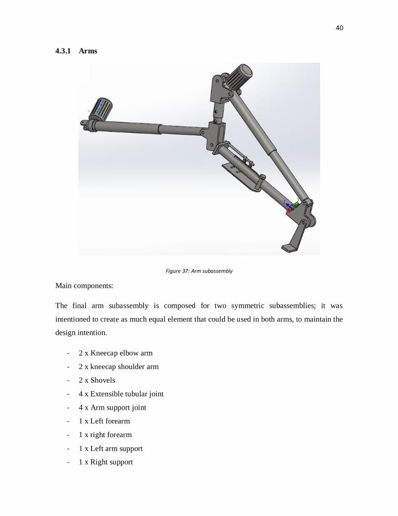
4.3.1 Arms
Figure 37: Arm subassembly
Main components:
The final arm subassembly is composed for two symmetric subassemblies; it was
intentioned to create as much equal element that could be used in both arms, to maintain the
design intention.
- 2 x Kneecap elbow arm
- 2 x kneecap shoulder arm
- 2 x Shovels
- 4 x Extensible tubular joint
- 4 x Arm support joint
- 1 x Left forearm
- 1 x right forearm
- 1 x Left arm support
- 1 x Right support

41
The arm design was not changing a lot after the first idea, it was based in the chest design
to create the retractile possibility and it was also created with cylindrical profiles. The
unique addition IS the arm support element; it allows the user to rest the arm and to create a
joint between the user and the structure to transmit the mechanical energy, it is an essential
element that should be combined with different sensors and electronic devices to make
possible the objective of the exoskeleton (carry big weight without using a big force), the
user’s arms and the exoskeleton’s arms should work synchronized, but it is a
complementary work for this main project.
Shovels
To dimension the box handle is needed to know the minimum measurements of the shovel
that will be used to hold the load.
The shovels will never be in distance lesser than 360 mm; all these measurements will be
used to calculate the box handle dimensions in a following section.
Height 10 mm
Length 50 mm
Width 70 mm
Figure 38: Shovel illustration

42
4.3.2 Material
This section is important to know the final weight of the entire structure, but as this project
will not be absolutely finished, it is possible that the final design version could suffer some
changes in the chosen material, when the axis studies would be realized, it should be
decided if the material has the correct specifications to reach our requirements or it should
be changed to another one with better characteristics for our necessities.
The material chosen for the structural elements is AISI1020 steel, in the following picture
(taken from the software SolidWorks) is possible to see the material specifications:
Figure 39: AISI 1020 steel SolidWorks specifications /Source: SolidWorks oftware
This kind of steel is chosen as first option for its good fatigue resistance and the easy
mechanization.
The total weight of the steel structure has a final weight of approximately 540 kg. It was
calculated with the measurement tool from SolidWorks.

43
4.3.3 Box
Limit dimension of the box to carry.
First, it must be calculated the limit dimensions of the box that is needed to be elevated.
The worst situation is when it is needed to raise the load from the floor. Then, the limit
dimensions of the box is when the exoskeleton is situated in the bottom dead center (BDC),
the arms in this positions are in the closest distance from the floor.
In addition, in this position can be found interferences between the shovels and base
structure when the arms are closed to its maximum angle (-10º), then some specifications
have to be done before doing this study.
After testing the structure with SolidWorks, the position that makes possible to carry the
load from the floor is this:
- Both arms completely extended and closed at -10º
- Both arms at -40º from the horizontal plane.
- Chest subassembly situated in its IDC.
Studying this position is possible to get the minimum volume that the box should have.
Figure 40: Example box dimensions
Width 360 mm
Length 309 mm
Height 360 mm

44
After having all this measurements, it is possible to define the minimum dimensions of the
handle, it has to be positioned at 310 mm from the floor and it has to maintain the
symmetry with the box to improve the stability.
Figure 41: Example box handle
Next is showed a representation of how the exoskeleton would carry and raise a minimum
size load.
Figure 42: Exoskeleton carrying a load Figure 43: Exoskeleton raising a load
Width 180 mm
Length 360 mm
Height 30 mm

45
4.3.4 Maximum height that the load could be raised
To determine this parameter, it is needed to move the exoskeleton until his maximum
height position. This position is determined as:
- Arms completely extended
- Arm turned 40º over the horizontal plane
- Structure in the top dead center (TDP)
After positioning the exoskeleton in this position it was possible to measurement the total
height that is possible to elevate the load.
It is a good result, this measurement simulates the height that a normal human could raise a
normal height, but in this case, it would be possible to do the same action but with a load
two or three time heavier than a normal person could carry.
4.3.5 Ideal transporting position
The ideal position to transport the load is where the gravity center is lower, but as one of
the goals of this project is to be care about the user comfort, the transport cannot be realized
in the bottom dead center (BDC), where the user should be all time completely flexed. It I
estimated that an average normal height is 500 mm, in this way the user is not in any of the
extremes positions.
The ideal transporting position is got with:
- Arm-forearm angle at 100º
- Seat at 500 mm from the footrest
- Elbow actuator completely closed
Maximum stacking height 2084 mm

46
After analyzing this position, a big problem was found; the visibility of the user can be
reduced when the load is in front of him. It is a big problem that should be studied and tried
to be solved in the next prototype design.
4.3.6 Manoeuvrability
In this section will be detailed which will be the needed workplace to use this exoskeleton
prototype carrying the maximum load of 50 kg.
First, the width and height corridor measurements will be defined to have enough space for
the exoskeleton realizing its goal.
These dimensions are established assuming that the user is working in the ideal position
and having a marge of 10 cm between the exoskeleton and the walls.
The minimum wall height should be 1680 mm if we assume the last assumptions; it is not a
problem because any industrial workplace has a minimum height of 3 or 4 meters.
To talk about the needed width, two different situations must be studied. It is considered the
following carrying position:
- Arms completely extended
- Arms opened at their maximum angle from the vertical (20º)

47
Situations:
1- The exoskeleton does not need to rotate, only carry the weight in straight direction.
In this situation the dimensions between both arms is 1480, and bearing in mind the marge
with the walls, the minimum corridor width must be 1580 mm
Figure 44: Absolute width dimension

48
2- The exoskeleton needs to rotate.
When the exoskeleton needs to rotate, it creates an imaginary pivoting axis in the middle
point between the wheel, the length between this point and the back wheel represents a
radius of an imaginary circumference. This radius has a length of 1400 mm.
Figure 45: Pivoting radius

49
But as the arms in the most extended position, the distance from the pivoting axis to the
farthest arm point must be added to the total measurement, also the marge with the walls
have to be counted, finally being the minimum corridor width in this position, 2305 mm.
Figure 46: Absolute pivoting dimension.

50
4.3.7 Exoskeleton storage
As last, an important aspect in the industrial field is the machinery storage.
The most compressed position is the one that is used as storage position. This position was
studied in section 3.5 Global dimensioning, but the measurements are shown in the
following table.
Figure 47: Storage width Figure 48: Storage position
Table 17: Exoskeleton storage dimensions.
SolidWorks rounded
measurement
Final dimension (with 100 mm to the wall)
Width (mm) 860 mm 1060 mm
Length (mm) 1500 mm 1700 mm
Height (mm) 1450 mm 1550 mm
51
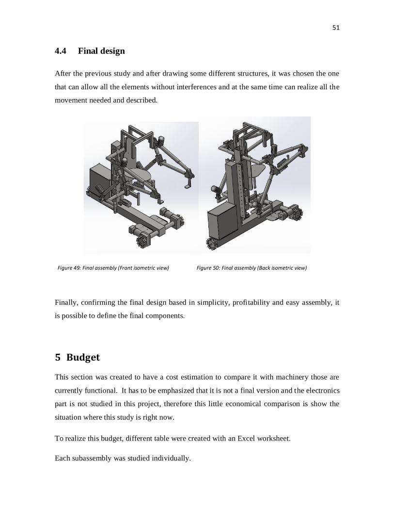
4.4 Final design
After the previous study and after drawing some different structures, it was chosen the one
that can allow all the elements without interferences and at the same time can realize all the
movement needed and described.
Figure 49: Final assembly (Front isometric view) Figure 50: Final assembly (Back isometric view)
Finally, confirming the final design based in simplicity, profitability and easy assembly, it
is possible to define the final components.
5 Budget
This section was created to have a cost estimation to compare it with machinery those are
currently functional. It has to be emphasized that it is not a final version and the electronics
part is not studied in this project, therefore this little economical comparison is show the
situation where this study is right now.
To realize this budget, different table were created with an Excel worksheet.
Each subassembly was studied individually.
52
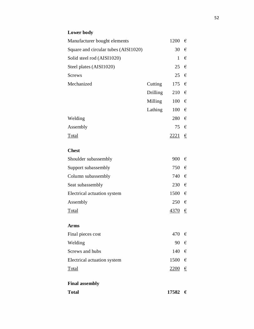
Lower body
Manufacturer bought elements
1200 €
Square and circular tubes (AISI1020)
30 €
Solid steel rod (AISI1020)
1 €
Steel plates (AISI1020)
25 €
Screws
25 €
Mechanized Cutting 175 €
Drilling 210 €
Milling 100 €
Lathing 100 €
Welding
280 €
Assembly
75 €
Total
2221 €
Chest
Shoulder subassembly
900 €
Support subassembly
750 €
Column subassembly
740 €
Seat subassembly
230 €
Electrical actuation system
1500 €
Assembly
250 €
Total
4370 €
Arms
Final pieces cost
470 €
Welding
90 €
Screws and hubs
140 €
Electrical actuation system
1500 €
Total
2200 €
Final assembly
Total
17582 €

53
After doing this estimation, it was searched another machinery that could realize the same
work as the exoskeleton.
Searching on internet, some devices were found, it was chosen the one that could realize
the same objective in the most similar way.
The chosen device is a forklift, in specific the model WP 3000 from the company CROWN,
its catalogue is added in Annex 2: Catalogues.
The main points that were studied are the general dimensions and the capacity to realize the
work. The forklift dimensions show the range that compounds all the models.
Table 18: Machine comparison
Exoskeleton Forklift
Height 1450 780-1197 mm
Width 860 712 mm
Length 1500 1799-1899 mm
Elevation height* 2048 750 mm
Rotation radius 1408 1534-1634 mm
Maximum raising weight 50 800 kg
Device weight (without battery) 540 490-535 kg
Price 17582 + Elect. Dev. 3000 €
*Maximum load raising height
The comparison gave promising results. The dimensions of the exoskeleton are little
enough to be competitive in the market while in other aspects are even better; the elevation
height is more than twice, allowing this better stack options, but on the other hand, the
estimated price of the exoskeleton is extremely high to be an available option.
There are still some options to improve the exoskeleton and reduce the cost, it would be
possible to change the material, even the design could be changed to give more stability
reducing the dimensions or even increasing the load weight that could be carried.

54
6 Conclusion
The realization of this project was done following the engineering design processes, it was
done a necessity recognition, followed by a problem definition, the synthesis of the design,
the essential analysis and optimization was done until the third design, as it is a thesis
report and the global goal of it is showing my engineering knowledge, the design process
stopped in this point and it continued to the evaluation step to finally finished in the
presentation.
In the final design, after realizing all needed modifications, I obtained a design that met all
the requirements initially aimed, the anthropometrical dimension for the dimensioning are
reflected in the design and the interfaces were successfully defined, allowing the desired
movement without interferences. As a result, the final prototype studied is considered to be
the simplest and the cheapest option.
Even the exoskeleton specifications are good enough to realize its goal; it still has to be
improved in many ways. As the intention is to design an exoskeleton, the next versions
should be evolved to a humanoid shape, the most important factor would be the movement
system, the design should allow the user working in many different workspaces, not only in
flat floors, the biggest restraint of this project.
Also, during the study it was possible to check that using the right element and materials,
the lifting capacity of this dispositive could be highly improved, combining this fact with a
good base stability, it would be possible to get a real exoskeleton that allows the user lifting
huge loads in many different spaces. These improvements could hide the high manufacture
cost and convert this project in a real market option.

55
7 Literature references
/1/ Elfdeportes. Digital magazine. Antropometria: necessidade de
constantes investigações para a efetiva contribuição na área da Ergonomia
http://www.efdeportes.com/efd149/antropometria-contribuicao-na-area-da-
ergonomia.htm
Retrieved: 25.03/2016
/2/ European Agency for Safety and Health at Work. Transtornos
musculoesqueléticos.
https://osha.europa.eu/es/themes/musculoskeletal-disorders
Retrieved: 25.04.2016
/3/ Felisberto, L. C.. Pascuoarelli, L. C. 2001. Dimensionamento preliminar de postos
de trabalho e produtos – modelos antropométricos em escala. In: ENCONTRO
NACIONAL DE ENGENHARIA DE PRODUÇÃO.Anais... VII International
Conference on Industrial Engineering e Operations Management, Salvador.
Proceedings, 1 CD ROM.
Retrieved: 23.03.2016
/4/ Lapunzina, P. Aielo H. 2002. Manual de antropometria normal y patologica: fetal,
neonatal, niños y adultos. Elsevier España, p.503.
https://books.google.fi/books?id=6dqdadnpvckC&printsec=frontcover&hl=es#v=o
nepage&q&f=false
Retrieved: 30.03.2016
/5/ MUEBLESDOMOTICOS. Medidas para diseñar sillas o asientos.
http://mueblesdomoticos.blogspot.fi/2010/12/medidas-para-disenar-sillas-o-
asientos.html
Retrieved: 05.04.2016
/6/ NATIONAL AERONAUTICS AND SPACE ADMINISTRATION. Man-Systems
Integration Standards. Revision B, July 1995. Volume I, Section 3
ANTHROPOMETRY AND BIOMECHANICS. http://msis.jsc.nasa.gov/sections/section03.htm#_3.2_GENERAL_ANTHROPOMETRICS
Retrieved: 07.04.2016

56
Catalogues
/7/ EMD. Gearbox BC-9
http://www.parvalux.com/downloads
Retrieved: 13.04.2016
/8/ HANGFA Omni wheel QML-20
http://www.hangfa.com/EN/omniwheel/QLM20.html
Retrieved: 10.04.2016
/9/ IGUS. DryLin TK-01 Lineal slide.
http://www.igus.com/wpck/3576/DryLin_T_Einstellbares_Spiel
Retrieved: 03.04.2016
/10/ MECVEL. Lineal Actuators ALI4 24-Vdc.
http://www.mecvel.com/linear-actuator-ali4-ac/
Retrieved: 03.04.2016
/11/ TROJAN. Battery. J185H-AC
http://www.trojanbattery.com/product/j185h-ac/
Retrieved: 07.04.2016

57
Table of contents: Figures
Figure 1: Anthropometrical characteristics table (measurements in cm) / Source: “Elfdeportes” 6
Figure 2: Bidimensional representation for measurements identification / Source: “Elfdeportes” 7
Figure 3: Dimensions used in the arm design / Source: Manual de Antropometria Normal Patológica. 8
Figure 4: Adjustable arm length 9
Figure 5: Adjustable forearm length 10
Figure 6: Total adjustable arm length 11
Figure 7: Adjustable shoulder length 13
Figure 8: Maximum and minimum distance between seat and shoulders / Source: Elfdeportes 14
Figure 9: Ajustable back height 14
Figure 10: Main distances for a sitting position person./Source: “Mueblesdomoticos” website 15
Figure 11: Anthropometrical dimension of a sitting person / Source: “Mueblesdomoticos” website 15
Figure 12: Final seat dimension 16
Figure 13: Sitting individual anthropometrical dimensions. 17
Figure 14: Back support height 17
Figure 15: General head dimensions/Source: Elfdeportes 18
Figure 16: Security structure dimensions 19
Figure 17: Buttock-knees distance / Source:Elfdeportes 19
Figure 18: Hip width dimension for both sexes / Sources: Elfdeportes. 20
Figure 19: Maximum footrest dimension 21 Figure 20: Maximum opening angle (+20º) 22
Figure 21: Minimum opening angle (-10º) 22 Figure 22: Maximum raising angle (+40º) 22
Figure 23: Minimum raising angle (-60º) 22
Figure 24: Minimum elbow angle 23
Figure 25: Maximum elbow angle 23
Figure 26: Minimum seat height 24
Figure 27: Maximum seat height 25
Figure 28: Most compressed position 25
Figure 29: Most extended position 26
Figure 30: ALI4 24-Vdc./ Source: Actuator catalogue. 29
Figure 31: Lineal table DryLin TK01 / Source: Lineal guide catalogue 33
Figure 32: Lower body, Chest and Arms subassemblies 34
Figure 33: Lower body subassembly 35
Figure 34: Omni wheel HAMFA QLM-20 37
Figure 35: Chest subassembly 38
Figure 36: Arm subassembly 40
Figure 37: Shovel illustration 41
Figure 38: AISI 1020 steel SolidWorks specifications /Source: SolidWorks oftware 42
Figure 39: Example box dimensions 43
Figure 40: Example box handle 44
Figure 41: Exoskeleton carrying a load 43
Figure 42: Exoskeleton raising a load 44
Figure 43: Absolute width dimension 47
Figure 44: Pivoting radius 48

58
Figure 45: Absolute pivoting dimension. 49
Figure 46: Storage width 48
Figure 47: Storage position 50
Figure 48: Final assembly (Front isometric view) 49
Figure 49: Final assembly (Back isometric view) 51
Figure 50: Vectorial directions 4
Table of contents: Tables
Table 1: Different actuator characteristics. 4
Table 2: Anthropometrical arm length measurements 8
Table 3: Anthropometrical forearm length measurements. 9
Table 4: Anthropometrical design measurementments for the arm and the forearm 10
Table 5: Dimensional range of the entire arm 11
Table 6: Different lengths for the different arm positions. 11
Table 7: Biacromial distance for both sexes 12
Table 8: Biacromial distance of the machine 12
Table 9: Adjustable position with biacromial distance. 13
Table 10: Dimensional range for the back height 14
Table 11: Human head anthropometrical dimensions. 18
Table 12: Buttock-knee dimensional range 20
Table 13: Hip width dimensional range 20
Table 14: Arm movements’ limitations 23
Table 15: Extreme exoskeleton dimensions 25
Table 16: Support plate measurements. 32
Table 17: Exoskeleton storage dimensions. 50
Table 18: Machine comparison 53

NOVIA UNIVERSITY OF APPLIED SCIENCES
Mechanical-Environmental Engineering
Bachelor's thesis: Exoskeleton: Prototype design
Annex 1: Analytical calculations
Oscar Teruel Guisado
The degree program of Environmental Engineering
Vaasa/Novia April 2016

Exoskeleton: Prototype design
Table of contents: Annex 1
1. Abbreviation and definitions .................................................................. 1
2. Calculation referred to the actuator election ......................................... 3
3. Calculation referred to the lineal guide election .................................... 4
3.1 Calculation of the moment that the lineal guide must bear ............................................. 4
4. Force calculation on the slides -guide set. ............................................ 11
4.1 Stress caused by the frontal flexion (around the “x” axis) .............................................. 12
4.2 Supported values verification ....................................................................................... 13
5. Calculations for wheel election ............................................................. 13
5.1 Minimum power needed to move the wheel. ............................................................... 14
6. Engine election ...................................................................................... 17
7. Battery calculations ............................................................................... 18
7.1 Total power needed for the set calculation ................................................................... 18

Analytical calculations 1
Exoskeleton: Prototype design
1. Abbreviation and definitions
Symbol Variable SI Unit
Forces Fmax Maximum force that the actuator has to bear N
Fx Force in “x” axis N
N Normal force N
Fmax All the weight over each wheel N
Fown_wheel Weight of the own wheel N
Fmin Minimum force to move the wheel N
Torques Tload Torque generated by the load Nm
Tarm Torque generated by the arms Nm
Tactuator Torque generated by the actuator Nm
Tchest Torque generated by the chest Nm
Tseat Torque generated by the seat Nm
Ttotal
Torque generated by the total sum of the load, arms,
chest, seat and actuator
Nm
Tposition_1 Final torque module in position 1 Nm
Tposition_2 Final torque module in position 2 Nm
Tposition_3 Final torque module in position 3 Nm
Tfx
Torque generated in the lineal guides on axis “x” in
position 1
Nm
Tfz
Torque generated in the lineal guides on axis “z” in
position 2
Nm

Analytical calculations 2
Exoskeleton: Prototype design
Tresistant Maximum torque generated by the wheel Nm
Tstarter Torque needed to start the movement Nm
Tres Maximum torque generated by all the structure Nm
Power Pwheel Power needed to move the wheel W
Ptotal Power needed to supply all the devices W
Velocities v Structure maximum velocity m/s
w Wheel angular velocity rad/s
Others d
Variable to represent the perpendicular distance in torque
calculations
mm
mt Total structure mass kg
mwheel Maximum mass that each wheel can carry kg
R Radius of the wheel mm
μr Eccentricity mm
Simultaneity factor

Analytical calculations 3
Exoskeleton: Prototype design
2. Calculation referred to the actuator election
To realize the calculation for the actuator that is situated in the base platform, is needed to
know the approximate weight that it will bear. It is known that for this configuration, the
actuator have to support the arm and back weight, and the user weight. These weights were
obtained with the measurement tool from SolidWorks software with AISI1020 as chosen
material.
In the following table are shown the different weights:
Table 19: Sum of the weights that the actuator should bear.
Unit Weight (kg) Total (kg)
Arms 2 20 40
Back 1 75 75
Operator 1 100 100
Load 1 100 100
315
⁄
Calculation the total reaction that it should bear and using a security marge, finally it was
selected the actuator “ALI4 24-Vdc” that could bear a maximum of 4100N. See catalogue
in Annex 2: Catalogues.
Figure 1: Catalogue detail showing the chosen actuator.

Analytical calculations 4
Exoskeleton: Prototype design
3. Calculation referred to the lineal guide election
3.1 Calculation of the moment that the lineal guide must bear
To choose a lineal table that allows the alternative vertical movement, movement generated
for the squat action, it must be considered the forces that act on the table. For that, the
moments generated for the load are calculated in the union point of the lineal guides and the
back. The loads that were considered are:
1- Raising load
2- Arm weight (including the flexion movement actuator)
3- The actuator that permits the raising and going down arm movement.
4- Chest weight
5- Maximum operator weight
Three different arm positions are chosen to decide which one is the most unfavorable.
To consider the tree dimensional system, a vector analysis was done and SI units system
was used.
All following matrix are based in the next vector expression:
[
]
Figure 51: Vectorial directions

Analytical calculations 5
Exoskeleton: Prototype design
The “i” vector direction corresponds to the exoskeleton width, the “j” vector direction to
the exoskeleton height and finally the “k” vector direction to the exoskeleton length.
Position 1:
Arms at 0º from the horizontal plane, both loaded with weight.
- Load to raise
It is supposed that in this position the load is raised with both arms with the same force
(50kg each arm).
Right arm load (50 kg) Left arm load (50 kg)
i j k i j k
0.432 0.641 1.287 -0.432 0.641 1.287
0 -500 0 0 -500 0
- Arm weight (including the flexion actuator)
Left arm load (25 kg) Right arm load (25 kg)
i j k i j k
0.432 0.641 0.71 -0.432 0.641 0.71
0 -250 0 0 -250 0
- The actuator that permits the raising and going down arm movement.
Left actuator (5 kg) Right actuator (5 kg)
i j k i j k
-0.391 0.32 0.323 0.391 0.32 0.323
0 -50 0 0 -50 0

Analytical calculations 6
Exoskeleton: Prototype design
- Chest weight.
Chest (75 kg)
i j k
0 0.361 0.11
0 -750 0
- User weight
User ( 100kg)
i j k
0 0.052 0.31
0 -1000 0
The resultant torque that the lineal table should support is:
i j k Resultant (Nm)
Tload 1287 0 0 1287
Tarm 355 0 0 355
Tactuator 32.3 0 0 32.3
Tchest 82.5 0 0 82.5
Tseat 310 0 0 310
Ttotal 2066.8 0 0 2066.8
It can be observed that in this position the lineal guides only work in flexion around the “x”
axis. The resultant moment in position 1 is:
| | | |
Position 2
Arms at 0º from the horizontal plane: Right arm loaded and turned 20º from the vertical
plane, left arm without load.
In this situation, it is supposed that the entire load is supported for only one arm. To do this
calculation the load is multiplied for a security factor of 2. With this security factor is
assumed that the dynamical load, the own weight or any other lateral unplanned impact are
counted.
This kind of load is hypothetical and it is not possible in the real life.

Analytical calculations 7
Exoskeleton: Prototype design
Following the same procedure as in the position 1, it is showed the vector analysis that give
as result the moment generated for each load:
- Load to raise
In this position, the most unfavorable situation would be that the maximum load (100 kg)
was elevated with only one arm.
Right arm load (100 kg) Left arm load (0 kg)
i j k i j k
0.747 0.641 1.21 -0.431 0.648 1.282
0 -1000 0 0 0 0
- Arm weight (including the flexion actuator)
Left arm load (25 kg) Right arm load (25 kg)
i j k i j k
0.554 0.641 0.71 -0.344 0.641 0.71
0 -250 0 0 -250 0
- The actuator that permits the raising and going down arm movement.
Left actuator (5 kg) Right actuator (5 kg)
i j k i j k
0.431 0.33 0.31 -0.39 0.33 0.31
0 -50 0 0 -50 0
Analytical calculations 8
Exoskeleton: Prototype design
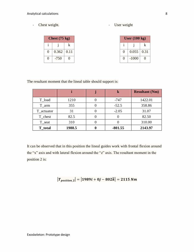
- Chest weight.
Chest (75 kg)
i j k
0 0.362 0.11
0 -750 0
- User weight
User (100 kg)
i j k
0 0.055 0.31
0 -1000 0
The resultant moment that the lineal table should support is:
i j k Resultant (Nm)
T_load 1210 0 -747 1422.01
T_arm 355 0 -52.5 358.86
T_actuator 31 0 -2.05 31.07
T_chest 82.5 0 0 82.50
T_seat 310 0 0 310.00
T_total 1988.5 0 -801.55 2143.97
It can be observed that in this position the lineal guides work with frontal flexion around
the “x” axis and with lateral flexion around the “z” axis. The resultant moment in the
position 2 is:
| | | |

Analytical calculations 9
Exoskeleton: Prototype design
Position 3
Arms at 40º from the horizontal plane: right arm with a load turned 20º from the vertical
plane, left arm without load.
As in the position 2, a security factor of 2 will be applied.
- Load to raise
In this position, the most unfavorable situation would be that the maximum load (100 kg)
was elevated with only one arm.
Right arm load (100 kg) Left arm load (0 kg)
i j k i j k
0.656 1.331 0.942 -0.431 0.639 1.278
0 -1000 0 0 0 0
- Arm weight (including the flexion actuator)
Left arm load (25 kg) Right arm load (25 kg)
i j k i j k
0.51 0.952 0.559 -0.367 0.949 0.559
0 -250 0 0 -250 0
- The actuator that permits the raising and going down arm movement.
Left actuator (5 kg) Right actuator (5 kg)
i j k i j k
0.431 0.353 0.255 -0.431 0.353 0.255
0 -50 0 0 -50 0

Analytical calculations 10
Exoskeleton: Prototype design
- Chest weight.
Chest (75 kg)
i j k
0 0.353 0.11
0 -750 0
- User weight
User (100 kg)
i j k
0 0.055 0.31
0 -1000 0
The resultant moment that the lineal table should support is:
i j k Resultant (Nm)
T_load 942 0 -650 1144.49
T_arm 279.5 0 -35.75 281.78
T_actuator 25.5 0 0 25.50
T_chest 82.5 0 0 82.50
T_seat 310 0 0 310.00
T_total 1639.5 0 -685.75 1777.14
It can be observed that in this position the lineal guides work with frontal flexion around
the “x” axis and with lateral flexion around the “z” axis. The resultant moment in the
position 3 is:
| | | |
After analyzing the results, it is clear that the most unfavorable frontal flexion is produced
in the position 1, however, the biggest lateral flexion is in position 2. On the other hand, in
any situation exist torsion forces (around “y” axis).
Having the most unfavorable moments that the lineal table must support (slides and guides
set), it is searched one that fulfills the requirements and general dimensions of the design.

Analytical calculations 11
Exoskeleton: Prototype design
After searching in the catalogues from different manufacturers, it was checked that the best
guide line is DryLinTTW-01-15. It can be seen in Annex 2: Catalogues.
To guarantee the correct operation and with the intention of sharing the forces and so
making them lower, it is decided to place two slides in each guide.
The distance between guides is the needed to avoid interferences with the actuator and it is
assumed that the vertical distance between both slides is the same length that one slide.
The slide and guide dimensions are given for the manufactured in the catalogue.
4. Force calculation on the slides -guide set.
Stress caused by the lateral flexion (Around the “z” axis)
First it is studied the lateral flexion (around the “z” axis). It will be used the biggest
moment value calculated in the previous section. This is the moment of the position 2:
| | | |
Therefore:
The moment respect the “z” axis is the force per distance since the application point to the
gravity center. To do the force calculation it is assumed that only two slides will support the
biggest part of the stress.

Analytical calculations 12
Exoskeleton: Prototype design
Table 20: Lateral flexion stress calculation (Fx)
Tfz (lateral shift)
Tfz 801 Nm
d 0.1075 m
Fz 3726 N
4.1 Stress caused by the frontal flexion (around the “x” axis)
Next is analyzed the frontal flexion phenomena (around “x” axis). For that it is taken the
biggest moment (Tfx) calculated in the previous section.
The chosen torque is the calculated in the position 1:
| | | |
Therefore:
It is assumed that the 4 slides are supporting the stress, for that:
Table 21: Frontal flexion stress calculation
Tfx (frontal shift)
Tfx 2067 Nm
d 0.1075 m
Fx 4807 N
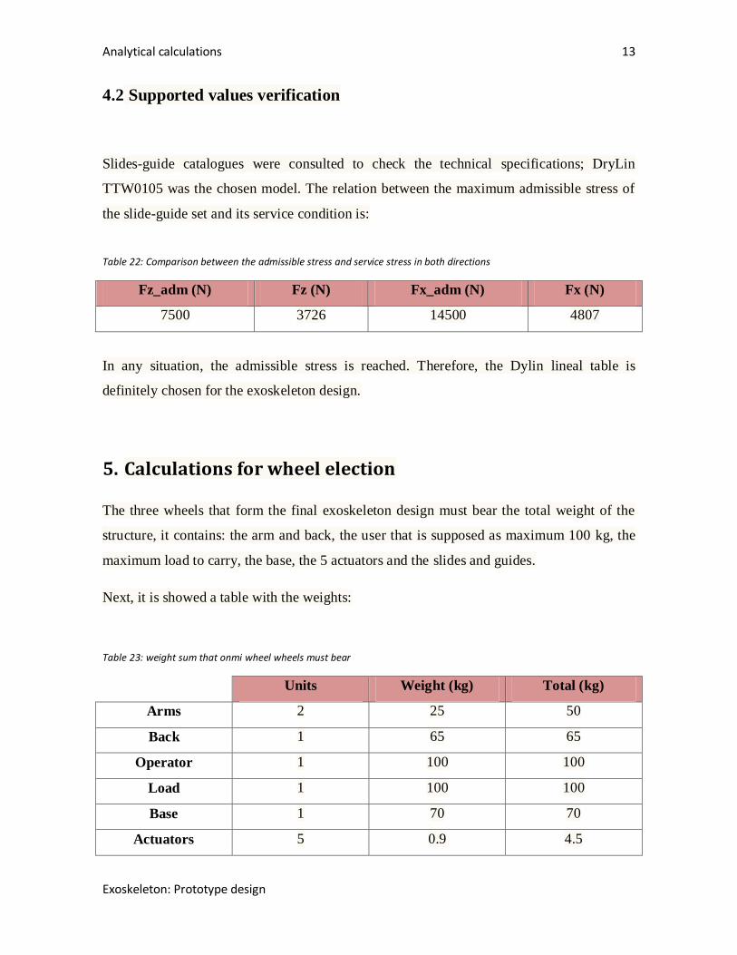
Analytical calculations 13
Exoskeleton: Prototype design
4.2 Supported values verification
Slides-guide catalogues were consulted to check the technical specifications; DryLin
TTW0105 was the chosen model. The relation between the maximum admissible stress of
the slide-guide set and its service condition is:
Table 22: Comparison between the admissible stress and service stress in both directions
Fz_adm (N) Fz (N) Fx_adm (N) Fx (N)
7500 3726 14500 4807
In any situation, the admissible stress is reached. Therefore, the Dylin lineal table is
definitely chosen for the exoskeleton design.
5. Calculations for wheel election
The three wheels that form the final exoskeleton design must bear the total weight of the
structure, it contains: the arm and back, the user that is supposed as maximum 100 kg, the
maximum load to carry, the base, the 5 actuators and the slides and guides.
Next, it is showed a table with the weights:
Table 23: weight sum that onmi wheel wheels must bear
Units Weight (kg) Total (kg)
Arms 2 25 50
Back 1 65 65
Operator 1 100 100
Load 1 100 100
Base 1 70 70
Actuators 5 0.9 4.5

Analytical calculations 14
Exoskeleton: Prototype design
Lineal guide 2 0.7 1.4
Slides 4 0.12 0.48
392
It must to be considered that the wheels also have to bear the battery and engines weight,
these values are still unknown. It is supposed that the three wheels should bear 70 kg for
these components.
⁄
Calculating the total reaction that one of the omni wheels must to bear, it was chosen the
QLM-20 Omni wheel that bears 160 kg exactly.
Figure 52: QLM-20 catalogue details.
5.1 Minimum power needed to move the wheel.
In real situations, the objects are not ideally rigid, they always have deformations. The
contact is not in the generatrix where P and N are placed. It means that the reactions appear
on the supports; reactions that create a torque that has to be beaten to start the wheel
rotation. It is equivalent to consider that the N normal force is displaced a determined
longitude (μr), it is the called rolling resistance coefficient.

Analytical calculations 15
Exoskeleton: Prototype design
Figure 53: Wheel distribution forces.
In critical conditions, to start the rolling, the applied torque, that in this situation is the
starter torque, must to be bigger that the resistant torque.
Being F the force applied on the wheel to move it.
⁄
For the following values chosen for the wheel:

Analytical calculations 16
Exoskeleton: Prototype design
And assuming an eccentricity:
The minimum force needed to start the wheel movement:
⁄
⁄
Finally, to calculate the power it should be assumed the exoskeleton speed (P in this section
means power):
Applying the security factor:
Each wheel needs an engine of 155 W to start the movement.

Analytical calculations 17
Exoskeleton: Prototype design
6. Engine election
To choose an engine to transmit the movement to the wheels it should bear in mind some
parameters, as the power, the torque that has to be transmitted and the velocity.
First, the resistance torque is calculated (Tres), it is the torque needed to be beaten to start
the movement of all the structure. Therefore:
⁄ ⁄
Defined the engine characteristics parameters, it is searched a commercial engine model
capable to provide these values. The most appropriate is the MDPM6350GB9.
Figure 54: Engine catalogue details. Model: MDPM6350GB9

Analytical calculations 18
Exoskeleton: Prototype design
7. Battery calculations
7.1 Total power needed for the set calculation
To perform the total power calculation that all the set can consume, with all the elements
working at the same time, it has to be counted as the wheel engines as the actuators in the
arms, shoulders and platform.
The previous value is a theoretical value, because it is supposed that in any moment all the
actuators and engines will work at the same time. Then, a simultaneity factor was applied.

Exoskeleton: Prototype design
NOVIA UNIVERSITY OF APPLIED SCIENCES
Mechanical-Environmental Engineering
Bachelor's thesis: Exoskeleton: Prototype design
Annex 2: Catalogues
Oscar Teruel Guisado
The degree program of Environmental Engineering
Vaasa/Novia April 2016

Exoskeleton: Prototype design

Exoskeleton: Prototype design
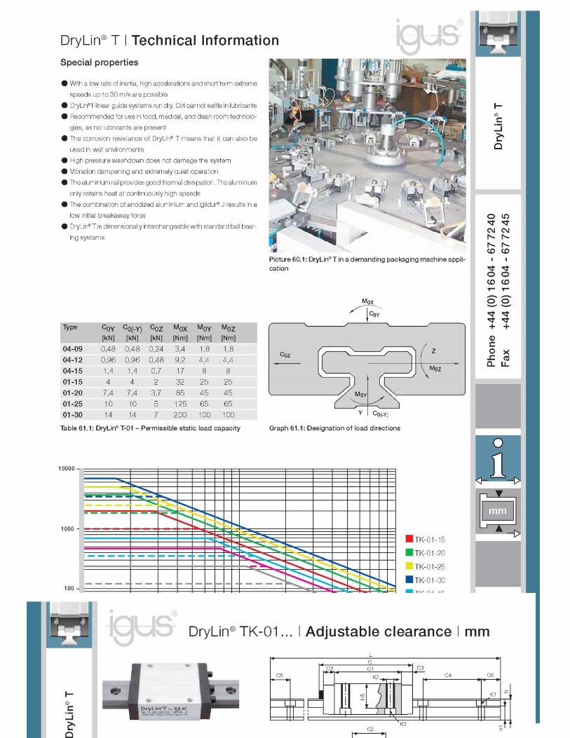
Exoskeleton: Prototype design

Exoskeleton: Prototype design

Exoskeleton: Prototype design

Exoskeleton: Prototype design

Exoskeleton: Prototype design

Exoskeleton: Prototype design

Exoskeleton: Prototype design
Exoskeleton: Prototype design
NOVIA UNIVERSITY OF APPLIED SCIENCES
Mechanical-Environmental Engineering
Bachelor's thesis: Exoskeleton: Prototype design
Annex 3: Construction drawings
Oscar Teruel Guisado
The degree program of Environmental Engineering
Vaasa/Novia April 2016

Exoskeleton: Prototype design
Table of contents
Final assembly Sketch Num: 1
Subassembly: Lower body Sketch Num: 2
Welded base Sketch Num: 3
Footrest Sketch Num: 4
Subassembly: Chest Sketch Num: 5
Security structure Sketch Num: 6
Subassembly: Shoulder Sketch Num: 7
Subassembly: Column Sketch Num: 8
Subassembly: Seat Sketch Num: 9
Subassembly: Support Sketch Num: 10
Subassembly: Arms Sketch Num: 11
Subassembly: Hand support Sketch Num: 12

Exoskeleton: Prototype design

Exoskeleton: Prototype design

Exoskeleton: Prototype design

Exoskeleton: Prototype design

Exoskeleton: Prototype design

Exoskeleton: Prototype design

Exoskeleton: Prototype design

Exoskeleton: Prototype design

Exoskeleton: Prototype design

Exoskeleton: Prototype design
10
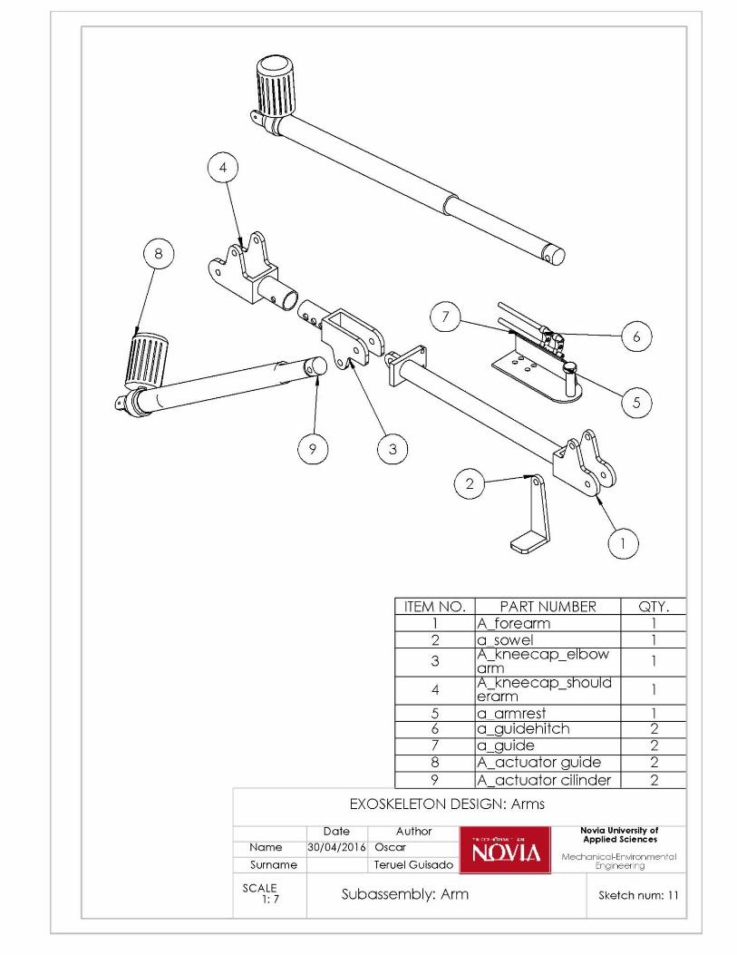
Exoskeleton: Prototype design

Exoskeleton: Prototype design