conclusion - boilerdesignsoftwareonline.com · web viewboiler design software online ....
TRANSCRIPT

Boiler Design Software Online Instructions for users
The Boiler Design Software Online, BDS runs in any Internet browser. Its user interface has been designed to allow user with a necessary theoretical and practical pre-knowledge in boiler designing and heat transfer calculations to quickly become familiar with it. A brief description of user interface follows.
On top of the opening page there is a list of available modules (Figure 1). Clicking on one brings up respective section where data are entered, calculations carried out and results displayed. Page can be scrolled up and down as usual in Internet browser.
Figure 1: Opening page
Hybrid module is used for this purpose. From the menu at top of the opening page a Hybrid boiler is clicked, which brings up the screen shown in Figure 2. On top of page there is an icon at the end of title. When hovering above it with a mouse pointer a small box next to mouse pointer appears “Click to enlarge”. Clicking on that icon brings up an image showing general image of a Hybrid boiler as shown in Figure 3. Clicking on x in upper right corner closes the image.
1

Figure 2: Hybrid boiler page
Figure 3: Hybrid boiler module title image
This way a help is provided for boiler geometry data input (see below) to illustrate the process and make sure entries are in valid limits to prevent erroneous data entry and by that unrealistic results.
First step is entering input data, which consist of fuel related data, general boiler operation data such as steam pressure etc., and boiler geometry data. Data entry process follows point-and-click fashion making it simpler for user.
2
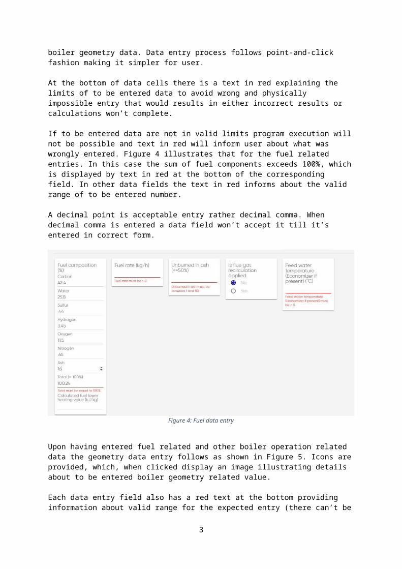
At the bottom of data cells there is a text in red explaining the limits of to be entered data to avoid wrong and physically impossible entry that would results in either incorrect results or calculations won’t complete.
If to be entered data are not in valid limits program execution will not be possible and text in red will inform user about what was wrongly entered. Figure 4 illustrates that for the fuel related entries. In this case the sum of fuel components exceeds 100%, which is displayed by text in red at the bottom of the corresponding field. In other data fields the text in red informs about the valid range of to be entered number.
A decimal point is acceptable entry rather decimal comma. When decimal comma is entered a data field won’t accept it till it’s entered in correct form.
Figure 4: Fuel data entry
Upon having entered fuel related and other boiler operation related data the geometry data entry follows as shown in Figure 5. Icons are provided, which, when clicked display an image illustrating details about to be entered boiler geometry related value.
Each data entry field also has a red text at the bottom providing information about valid range for the expected entry (there can’t be valid range for some data as for instance fuel rate where the only limitation is that it must be greater than 0 and it’s up to user to know what number is physically possible and sensible).
3

Figure 5: Hybrid boiler geometry data input
Clicking on the icon at the end of Furnace geometry data title in Figure 5 brings up a picture shown in Figure 6 illustrating the required data for that segment.
Figure 6: Hybrid boiler furnace geometry data explanation
4

Clicking on icon at the end of Tube assembly geometry data title in Figure 5 brings up the picture shown in Figure 7 illustrating the required geometry data for that segment.
Figure 7: Hybrid boiler geometry data explanation
At bottom of the page there are two bottons, CALCULATE and RESET shown in Figure 8. When all data fields contain correct numbers clicking on CALCULATE botton launches a calculation process that takes few seconds at the most afterwards results are displayed.
If some of input data are not correct a text in red appears above CALCULATE bottom (shown in image below). Scrolling up reveals the data entry field with red text at the botttom indicating this particular number is incorrect. Clicking on RESET button clears all data entry fields for the fresh start.
Figure 8: Calculation start & Reset button
There are fields in blue titled SAMPLE 1 and SAMPLE 2 (in this case there are two samples, more in other modules). Clicking on these fields launches calculations with preset data. Data entry fields are automatically filled with numbers, CALCULATE button is automatically invoked and results are
5

displayed. This way user can learn about details needed to fully comprehend the software use in an easy-to-follow way.
NOTE: CALCULATE field is not active. Buying time activates it for the set duration. Clicking on it without having purchaced time before brings up an alert that time needs to be purchaced.
Upon pressing CALCULATE button calculations follow and results appear as shown in Figure 9.
Figure 9: Hybrid boiler calculation results
Above results title (HEAT TRANSFER IN HYBRID BOILER) there are four icons. Howering with mouse pointer above each one displays a small rectangle with text explaing what each icon does:
1. First icon from the left: »Print«2. Second icon: »Save to file«3. Third icon: »Save project (Excel file)«4. Fourth icon: »Import project«.
Hence, first icon prints the results of calculations, second icon saves them to file, third icon saves input data to disk as Excel file and fourth icon imports input data for a particular case in one go to save time when that case is used at later time.
Clicking on Print icon produces a screen shown in Figure 10. Pressing Esc brings back previous screen with results.
6
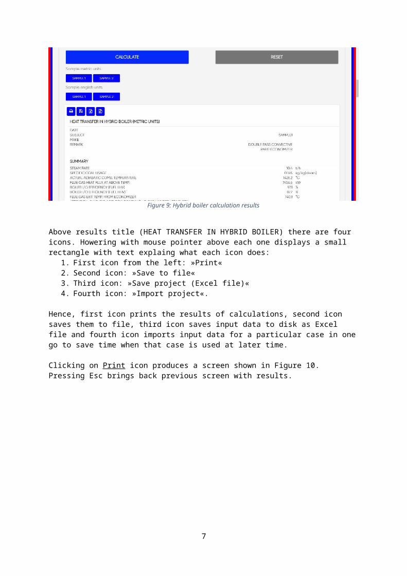
Figure 10: Print submenu for prinout of results
Clicking on Save to file icon brings up a screen shown in Figure 11 where file name is entered and location on computer to chose where to save the file. Text file is created to be used in word processors.
Figure 11: Save to file submenu
Clicking on Save project icon brings up a screen shown in Figure 12 where file name is entered and location on computer to chose where to save the file. Excel is created.
7

Figure 12: Save project
Clicking on Import project icon brings up a screen shown in Figure 13 where file saved in Save project shown above is listed. Selecting it and pressing Open field imports all input data in one go.
Figure 13: Import project
ConclusionThe lines above show in a brief fashion a complete process of data entering, carrying out heat transfer calculations and displaying & handling results with Boiler Design Software Online application. User interface is simple and easy to follow for an user with needed theoretical and practical pre-knowledge in boiler heat transfer. All modules follow same pattern.
8