concrete overlay field application program · iowa state university does not discriminate on the...
TRANSCRIPT
Concrete Overlay Field Application Program
Iowa Task Report US 18 Concrete Overlay Construction Under TrafficMay 2012Sponsored throughFederal Highway Administration (DTFH-61-06-H-00011 (Work Plan 13))

About the National CP Tech Center
The mission of the National Concrete Pavement Technology Center is to unite key transportation stakeholders around the central goal of advancing concrete pavement technology through research, tech transfer, and technology implementation.
Disclaimer Notice
The contents of this report reflect the views of the authors, who are responsible for the facts and the accuracy of the information presented herein. The opinions, findings and conclusions expressed in this publication are those of the authors and not necessarily those of the sponsors.
The sponsors assume no liability for the contents or use of the information contained in this document. This report does not constitute a standard, specification, or regulation.
The sponsors do not endorse products or manufacturers. Trademarks or manufacturers’ names appear in this report only because they are considered essential to the objective of the document.
Non-Discrimination Statement
Iowa State University does not discriminate on the basis of race, color, age, religion, national origin, sexual orientation, gender identity, genetic information, sex, marital status, disability, or status as a U.S. veteran. Inquiries can be directed to the Director of Equal Opportunity and Compliance, 3280 Beardshear Hall, (515) 294-7612.
Iowa Department of Transportation Statements
Federal and state laws prohibit employment and/or public accommodation discrimination on the basis of age, color, creed, disability, gender identity, national origin, pregnancy, race, religion, sex, sexual orientation or veteran’s status. If you believe you have been discriminated against, please contact the Iowa Civil Rights Commission at 800-457-4416 or Iowa Department of Transportation’s affirmative action officer. If you need accommodations because of a disability to access the Iowa Department of Transportation’s services, contact the agency’s affirmative action officer at 800-262-0003.
The preparation of this document was financed in part through funds provided by the Iowa Department of Transportation through its “Agreement for the Management of Research Conducted by Iowa State University for the Iowa Department of Transportation” and its amendments.
The opinions, findings, and conclusions expressed in this publication are those of the authors and not necessarily those of the Iowa Department of Transportation or the U.S. Department of Transportation Federal Highway Administration.

Technical Report Documentation Page
1. Report No. 2. Government Accession No. 3. Recipient’s Catalog No. Part of DTFH-61-06-H-00011 (W13)
4. Title and Subtitle 5. Report Date Concrete Overlay Field Application Program Iowa Task Report: US 18 Concrete Overlay Construction Under Traffic
May 2012 6. Performing Organization Code
7. Author(s) 8. Performing Organization Report No. James K. Cable 9. Performing Organization Name and Address 10. Work Unit No. (TRAIS) National Concrete Pavement Technology Center Iowa State University 2711 South Loop Drive, Suite 4700 Ames, IA 50010-8664
11. Contract or Grant No.
12. Sponsoring Organization Name and Address 13. Type of Report and Period Covered Federal Highway Administration U.S. Department of Transportation 400 7th Street SW Washington, DC 20590
Iowa Task Report 14. Sponsoring Agency Code DTFH-61-06-H-00011 (W13)
15. Supplementary Notes Visit www.cptechcenter.org for color pdfs of this and other research reports. 16. Abstract The National Concrete Pavement Technology Center, Iowa Department of Transportation, and Federal Highway Administration set out to demonstrate and document the design and construction of portland cement concrete (PCC) overlays on two-lane roadways while maintaining two-way traffic. An 18.82 mile project was selected for 2011 construction in northeast Iowa on US 18 between Fredericksburg and West Union.
This report documents planning, design, and construction of the project and lessons learned. The work included the addition of subdrains, full-depth patching, bridge approach replacement, and drainage structural repair and cleaning prior to overlay construction. The paving involved surface preparation by milling to grade and the placement of a 4.5 inch PCC overlay and 4 foot of widening to the existing pavement. In addition, the report makes recommendations on ways to improve the process for future concrete overlays.
17. Key Words 18. Distribution Statement overlays under traffic—pavement rehabilitation—PCC overlays—two-lane construction traffic
No restrictions.
19. Security Classification (of this report)
20. Security Classification (of this page)
21. No. of Pages 22. Price
Unclassified. Unclassified. 122 NA
Form DOT F 1700.7 (8-72) Reproduction of completed page authorized


CONCRETE OVERLAY FIELD APPLICATION PROGRAM
IOWA TASK REPORT US 18 CONCRETE OVERLAY CONSTRUCTION
UNDER TRAFFIC
Iowa Task Report May 2012
Principal Investigator Tom Cackler
Director National Concrete Pavement Technology Center
Iowa State University
Author James K. Cable, PE
Cable Concrete Consultation
Sponsored by The Federal Highway Administration
As part of Concrete Overlay Field Application Program
DTFH-61-06-H-00011 (W13)
A report from National Concrete Pavement Technology Center
Institute for Transportation Iowa State University
2711 South Loop Drive, Suite 4700 Ames, IA 50010-8664 Phone: 515-294-8103
Fax: 515-294-0467 www.cptechcenter.org


v
TABLE OF CONTENTS
ACKNOWLEDGMENTS ............................................................................................................. xi
EXECUTIVE SUMMARY ......................................................................................................... xiii
BACKGROUND .............................................................................................................................1
INTRODUCTION ...........................................................................................................................1
SCOPE OF ACTIVITIES ................................................................................................................2
CONSTRUCTION PROJECT DESCRIPTION ..............................................................................2
CONSTRUCTION ACTIVITIES ....................................................................................................6
Overlay Project Selection and Evaluation ...........................................................................6
Historical Data Review ............................................................................................6 Project Level Data Collection ..................................................................................6 Visual Examination ..................................................................................................7
A. Overlay Depth Design..............................................................................................9 B. Construction Communications...............................................................................10
Public Input ............................................................................................................11 C. Construction Staging ..............................................................................................12 D. Subdrain Installation ..............................................................................................15 E. Concrete Full-Depth Patching................................................................................21 F. Longitudinal Joint Repair Patching .......................................................................30 G. Miscellaneous Drainage and Grading Work ..........................................................33 H. Bridge Approaches, Transitional Sections, and Shoulder Strengthening ..............38
Transitional Sections ..............................................................................................38 Bridge Approach Sections .....................................................................................39 Shoulder Strengthening ..........................................................................................41
I. Surface Surveys .....................................................................................................44 J. Surface Preparation for Overlays ...........................................................................49 K. Pavement Widening ...............................................................................................54 L. Pavement Overlay Paving Plan ..............................................................................59
M. Construction ...........................................................................................................60 N. Traffic Control Solutions During Project Construction .........................................76
PLANNING, DESIGN, AND CONSTRUCTION LESSONS LEARNED ..................................86
A. Project Selection and Construction Project Planning ............................................86 Project Selection ....................................................................................................86
Traffic Constraints .................................................................................................87 Overlay Design Plans .............................................................................................87
B. Overlay Depth Design............................................................................................88 C. Construction Project Description ...........................................................................88 D. Construction Communications...............................................................................88 E. Construction Staging ..............................................................................................89 F. Subdrain Installation ..............................................................................................90 G. Concrete Full-Depth Patching................................................................................90

vi
H. Longitudinal Joint Patching ...................................................................................91
I. Miscellaneous Drainage & Grading.......................................................................91 J. Bridge Approaches, Transitional Sections & Shoulder Strengthening ..................91 K. Surface Surveys .....................................................................................................92 L. Surface Preparation for Overlays ...........................................................................92 M. Pavement Widening ...............................................................................................93 N. Pavement Overlay Paving Plan ..............................................................................93 O. Construction ...........................................................................................................93 P. Traffic Control during Project Construction ..........................................................94
RECOMMENDATIONS FOR FUTURE PCC OVERLAY DESIGN AND CONSTRUCTION 94
Planning and Project Selection ..........................................................................................94 Overlay Depth Design........................................................................................................95 Construction Communications...........................................................................................95
Construction Staging ..........................................................................................................95 Subdrain Installation ..........................................................................................................96 Concrete Full-Depth Patching............................................................................................96 Longitudinal Joint Patching ...............................................................................................96 Miscellaneous Drainage and Grading Work ......................................................................97 Bridge Approaches, Transitional Sections and Shoulder Strengthening ...........................97 Surface Surveys .................................................................................................................98 Surface Preparations for Overlays .....................................................................................98 Pavement Widening ...........................................................................................................99 Pavement Overlay Paving Plan ..........................................................................................99 Construction .......................................................................................................................99 Traffic Control Solutions during Construction ................................................................100
APPENDIX A. CONTRACTOR PAVING PLAN AND CPM CHART ...................................101
APPENDIX B. HAUL ROAD MAP ...........................................................................................103
APPENDIX C. CONCRETE MIX DESIGN AND PROPERTIES ............................................104

vii
LIST OF FIGURES Figure i. Roadway location and site map (inset).......................................................................... xiii Figure 1. Existing pavement east end ..............................................................................................3 Figure 2. Existing pavement east end ..............................................................................................3 Figure 3. Existing pavement west end .............................................................................................4 Figure 4. Existing pavement west end .............................................................................................4 Figure 5. Typical cross section and jointing diagram (BOP to CR W14) .......................................5 Figure 6. Typical cross section and jointing diagram (CR W14 to EOP) ........................................5 Figure 7. Proposed roadway cross section .......................................................................................5 Figure 8. Wheel saw ......................................................................................................................16 Figure 9. HMA squeeze-out materials ...........................................................................................16 Figure 10. Tiling trencher ..............................................................................................................17
Figure 11. Subdrain installation .....................................................................................................17 Figure 12. Granular backfill operation ...........................................................................................18 Figure 13. Subdrain trench finishing .............................................................................................18 Figure 14. Power brooming ...........................................................................................................19 Figure 15. Subdrain outlet excavation ...........................................................................................19 Figure 16. Subdrain outlet backfilling ...........................................................................................20 Figure 17. Subdrain boulder removal ............................................................................................20 Figure 18. Existing subdrain repair ................................................................................................21 Figure 19. Full-depth patch area ....................................................................................................22 Figure 20. Full-depth patch area with multiple distresses .............................................................22 Figure 21. Sawing around patch area .............................................................................................23 Figure 22. Patch area demolition ...................................................................................................24 Figure 23. Patch area excavation ...................................................................................................24
Figure 24. Completed patch excavation.........................................................................................25 Figure 25. Compacted patch area subgrade ...................................................................................25 Figure 26. Concrete delivery for patches .......................................................................................26 Figure 27. Full-depth patch surface finish .....................................................................................26 Figure 28. Patch curing ..................................................................................................................27 Figure 29. Patching traffic control .................................................................................................28 Figure 30. Patching flagger station ................................................................................................28
Figure 31. Patching lane delineation ..............................................................................................29 Figure 32. Longitudinal patch area ................................................................................................30 Figure 33. Longitudinal patch removal milling .............................................................................31 Figure 34. Longitudinal patch filling device..................................................................................31 Figure 35. Longitudinal patch filling .............................................................................................32
Figure 36. Longitudinal joint vibrating roller ................................................................................32
Figure 37. Longitudinal joint vibrating plate compactor ...............................................................33
Figure 38a. RCB ............................................................................................................................34 Figure 38b. RCB cleaning..............................................................................................................34 Figure 39a. Culvert extension/relay ...............................................................................................35 Figure 39b. Entrance pipe placement .............................................................................................35 Figure 40. Culvert plugging ...........................................................................................................36 Figure 41. Culvert pushing equipment...........................................................................................37

viii
Figure 42. Culvert pushing pit .......................................................................................................37
Figure 43. EOP transition section ..................................................................................................38 Figure 44. Bridge transition section ...............................................................................................39 Figure 45. Paving notch replacement .............................................................................................40 Figure 46. Bridge approach base preparation ................................................................................40 Figure 47. Paved bridge shoulder ..................................................................................................41 Figure 48. Temporary barrier traffic control..................................................................................41 Figure 49. Shoulder strengthening in place ...................................................................................42 Figure 50. Pavement and shoulder strengthening removal ............................................................43 Figure 51. Marked survey control point ........................................................................................45 Figure 52. Control point cap ..........................................................................................................45 Figure 53. Cross-section survey points ..........................................................................................47 Figure 54. Milling to grade, pass #1 ..............................................................................................51
Figure 55. HMA millings stockpile ...............................................................................................51 Figure 56. Total station mill control ..............................................................................................52 Figure 57. Milled PCC full-depth patch ........................................................................................52 Figure 58. Irregular milled surface ................................................................................................53 Figure 59. Widening preparation ...................................................................................................55 Figure 60. Milled widening unit area .............................................................................................55 Figure 61. Widening edge cleaning ...............................................................................................56 Figure 62. Slipform padline preparation ........................................................................................56 Figure 63. Widening final joint ......................................................................................................57 Figure 64. Shoulder material stockpile ..........................................................................................58 Figure 65. Tie bar location device .................................................................................................61 Figure 66. Tie bar installation ........................................................................................................61 Figure 67. Tie bar clip layout .........................................................................................................62
Figure 68. Tie bar clip automation .................................................................................................62 Figure 69. Pilot car operation.........................................................................................................63 Figure 70a. Slipform paver ............................................................................................................63 Figure 70b. Slipform paver burlap drag .........................................................................................64 Figure 71. Workbridge and burlap drag .........................................................................................64 Figure 72. Cure/texture machine....................................................................................................65 Figure 73. Cure/texture machine guidance control ........................................................................65
Figure 74. Robotic total station ......................................................................................................66 Figure 75. Stringless paver controller ............................................................................................66 Figure 76. Control prisms ..............................................................................................................67 Figure 77. Prism 1 Site (middle of photo) .....................................................................................68 Figure 78. Prism 2 Site (middle of photo) .....................................................................................68
Figure 79. Prism 3 Site (near second power pole) .........................................................................69
Figure 80. Stringless survey crew vehicles ....................................................................................69
Figure 81. Dual total station control ..............................................................................................70 Figure 82. Paver vibrator monitor ..................................................................................................71 Figure 83. GSI sensors ...................................................................................................................71 Figure 84. GSI monitor ..................................................................................................................72 Figure 85. Central mix concrete batch plant ..................................................................................72 Figure 86. Transverse joint saws ...................................................................................................74
ix
Figure 87. Longitudinal joint saws ................................................................................................75
Figure 88. Lane channelizers .........................................................................................................77 Figure 89. Centerline safety wedge slipform .................................................................................78 Figure 90. Centerline safety wedge extrusion gate ........................................................................78 Figure 91. Centerline wedge concrete access ................................................................................79 Figure 92. Centerline wedge concrete deposit ...............................................................................79 Figure 93. Centerline wedge bond breaker applicator ...................................................................80 Figure 94. Centerline wedge removal ............................................................................................80 Figure 95. Centerline wedge removal loaders ...............................................................................81 Figure 96. BOP Bridge #1 traffic control ......................................................................................82 Figure 97. Bridge #1 EBL transition..............................................................................................82 Figure 98. HMA runout .................................................................................................................84
LIST OF TABLES
Table i. Iowa DOT six-stage project construction plan summary ............................................... xiv Table ii. Project staging plan .........................................................................................................xv Table 1. Rehabilitation alternatives identified for this section of roadway .....................................8 Table 2. Iowa DOT six-stage project construction plan details .....................................................12 Table 3. Project staging plan ..........................................................................................................14 Table 4. Iowa DOT six-stage traffic control plan summary ..........................................................76


xi
ACKNOWLEDGMENTS
This project is the result of the construction industry playing a role to help technology move forward to meet the needs of the traveling public in Iowa. The project began with the various Iowa Department of Transportation (DOT) District Offices asking the concrete paving industry for a concrete overlay alternative that could be built under traffic.
Through their cooperation with the Federal Highway Administration (FHWA), the National Concrete Pavement Technology Center funded this task to monitor the design and construction of the US 18 unbonded concrete overlay in Iowa under traffic and document the lessons learned.
This task was made possible by the cooperation of the Iowa DOT District 2 staff helping to identify a location. The Offices of Construction, Materials, Design, and Contracts made the project a reality. Information from the Iowa DOT Records Center played a role in understanding what currently existed in the pavement structure and how it would play into the performance of the overlay. The Office of Transportation Data supplied existing traffic data prior to and during the construction to give the designers a look at the traffic impacts of one-lane construction.
The staff of Manatt’s, Inc. and the New Hampton resident construction office deserves particular recognition for carrying out the work.
This project has been a team effort is a tribute to the cooperation in the highway industry between owners, researchers, and contractors to meet the public transportation needs in Iowa.


xiii
EXECUTIVE SUMMARY
The National Concrete Pavement Technology Center, Iowa Department of Transportation (DOT), and Federal Highway Administration set out to demonstrate and document the design and construction of a portland cement concrete (PCC) overlay on a two-lane roadway while maintaining through traffic. The work was scheduled for an 18.82 mile section of US 18 in northeastern Iowa in the summer of 2011 (Figure i).
Figure i. Roadway location and site map (inset)
The documentation part of this project involved the oversight of the construction process with a look at how well it worked and what could be improved. This project is the first official construction of a PCC overlay on a two-lane road in Iowa while maintaining through traffic.
The project involved the construction operations of adding longitudinal subdrains, full-depth pavement patching, bridge approach repair and guardrail updating, off-road drainage repair and improvement work, surface milling, PCC overlay placement, traffic control, and shoulder surfacing. All items except the drainage work were done with the aid of pilot car operations and single-lane traffic through the work areas. Each of these operations was monitored for seamless construction and obstacles to early completion of the work.

xiv
Iowa DOT specifications for this project called for work zone lengths of 2 miles for subdrain and patching work. Bridge work was accomplished with the use of single-lane traffic controlled with traffic signals. The overlay paving and shouldering work were allowed to have a 3.5 mile work area with the use of the pilot car and single-lane traffic. Cross road traffic was denied only while overlay pavement was being placed, cured, and the shoulder stone was placed.
The existing pavement on this project consisted of an existing 1938 PCC pavement of 18 or 20 foot in width that had been overlaid with asphaltic concrete multiple times to form a 6 inch overlay of the original surface and asphalt or PCC widening units that formed the 24 foot wide roadway.
The westerly portion of the project also contained an asphalt surface treatment that was raveling and rutting in the wheel paths. A large amount of the same section exhibited transverse joint tenting due to the deterioration of the underlying original pavement joints.
The plans called for the removal of the surface to a depth of 0.5 inches to remove the surface treatment. The project milling was later changed to allow for a milling depth of up to 1.5 inches at centerline and a 2% cross slope to correct cross-section irregularities. The state of Iowa has a very large number of miles of primary road that are constructed in this manner.
This project called for the widening of the existing pavement 4 feet on each side with PCC, and the placement of a 4.5 inch PCC overlay across the entire new pavement width.
To accomplish the overlay project, the Iowa DOT developed a six-stage construction plan as outlined in Table i.
Table i. Iowa DOT six-stage project construction plan summary
Stage Summary 1 Construct the subdrains, patching, and drainage work and erosion control on the east one
third of the project under traffic. 2 Rehabilitate the bridge approaches and railing on four bridges located in the west two
thirds of the project while allowing through traffic. 3 Construct the trenches for the shoulder widening, place the overlay and shouldering, and
open the east one third of the project to two-lane traffic. At the same time, construct the subdrains and patching on the west two thirds of the project while maintaining through traffic on the entire length of the project.
4 Mill to remove the surface treatment on the west two thirds of the project while maintaining through traffic.
5 Place the overlay and widening on the west two thirds of the project while maintaining through traffic.
6 Complete the construction of paved connections and turn lanes at three paved county road connection. Place required rumble strips on the shoulders of the length of the pavement.

xv
It became apparent early in the project that time and money could be saved if individual operations were allowed to begin at one end of the project and progress through the project in one time period. Secondly, a review of the pavement surface conditions resulted in the decision to mill the entire length of project surface to reduce concrete requirements and develop a uniform overlay depth. These decisions resulted in a staging plan that resembled what is shown in Table ii.
Table ii. Project staging plan
Stage Description 1 Construct subdrains, patching, and drainage work across the project by beginning at the
end of project (EOP) and working westerly to the beginning of project (BOP). Two-mile work zones were used for the subdrainage and patching work that allowed for two-mile gaps between operations and an orderly construction by each subcontractor. The drainage subcontractor was able to work on the shoulders and in the side ditches to minimize conflicts between the three groups.
2 Rehabilitate the bridge approaches and railing on four bridges in the west two thirds of the project.
3 Mill the surface from the EOP westerly to the BOP in one operation. 4 Place the overlay pavement and shoulder stone from the EOP to the BOP in one
continuous operation. 5 Complete the construction of paved connections and turn lanes at three paved county
road connection. Place required rumble strips on the shoulders of the length of the pavement.
Future staging plans are recommended by the highway owner with the allowance for consideration of contractor plans that can meet the agency goals while saving time and money for all.
The project included the installation of some 48,422 feet of longitudinal subdrain along the edge of the existing pavement at 113 locations in the west two thirds of the project. At the same time, the project called for 641 full-depth patches along 13 of the 18.82 miles of project. These two operations identified the reason for operations to work from the EOP to the BOP. Both the subdrain and patching work could follow each other with only minor conflicting times and locations. Longitudinal joint patching of the joint between the original pavement and the existing widening units could be eliminated if the existing widening is milled to all for a single widening unit of uniform depth for the new pavement.
Bridge rehabilitation and guardrail upgrades proved to be a key item in the overall scheduling of the project. The work included the replacement of bridge approach slabs and the notches on the back of the abutments. This work is a time-consuming and labor-intensive item. Work zones for these activities can conflict with those for the other items of work previously discussed. Recommendations for improvement include placement of the pavement with a slipform paver and longer work site delineation to allow for both ends of the bridge in one lane to be placed at once.

xvi
Bridge approach slabs and transition slabs (transition in elevation from the existing pavement to the top of the new overlay) form a natural length of pavement that can be done with conventional paving equipment. The result is more efficient and smoother transitions between the overlay and the bridge elevations. These sections of pavement can be built the season or months before the overlay is to be constructed. A simple asphaltic concrete wedge at the end of the transitions allows them to be used until the overlay reaches this point in the project.
Highway agencies and contractors are interested in managing the amount of concrete required for the overlay. Milling of the entire asphaltic concrete surface to a uniform longitudinal profile and transverse slope helps reduce the risk of concrete overruns and improves the uniformity of the overlay depth. Milling depths must not reduce the structure of the existing pavement beyond that required by the overlay designer. Milling the existing widening unit to a depth of the new widening unit reduces the number of longitudinal joints in this area from two to one.
The milling on this project was conducted with control from total robotic stations (stringless milling) from a computer model of the longitudinal centerline profile and given 2% cross slope on the final overlay surface. The same model and equipment guided the slipform paver on this project. Concrete quantity overrun was reduced from 126% on the plans to 104% in actual placement. The reduction was the result of a project developed computer surface model based on a 9 shot cross section at 50 foot intervals along the existing surface prior to milling.
Paving and traffic control plans for this project allowed the contractor to place up to 3.5 miles of single-lane pavement and then stop paving until this section reached opening strength, was shouldered, and traffic striping was applied. This approach proved to require 7.5 days to complete the work in the first lane and prepare the second lane for paving.
At the end of that time, the paving operation backed up to the beginning of the work and placed the second lane for a distance of 3.5 miles. Paving stopped at this point to wait for pavement cure time, shouldering, and traffic stripping. Concrete placement could then proceed 3.5 miles in the second lane and repeat the process.
This process proved to be very time-consuming and costly for the paving crew. Decisions were made to open a second paving work area near the middle of the project and operate two paving areas at the same time. In this way, the paving crew is working approximately 6 out of 7 days a week.
Current equipment design allows the contractor to move the paving spread from one site to the other in less than one day. The addition of the stringless paving equipment and model allows the contractor to make these moves quickly without limitations of stringline placement and removal.
Traffic control was a major issue in the design of this project. The intent was to allow for through traffic at all times with the use of minimal delays and pilot car operations 24 hours a day and 7 days a week (24/7). The system on this project included manual traffic controls and flaggers at each end of the work zone. The addition of the flaggers was a very effective deterrent

xvii
to impatient drivers. Side roads were blocked during the actual paving operations until the opening concrete strength was reached.
The overlay was cured with conventional “white-pigmented” spray-on cure. This cure was placed immediately behind the finishing operations.
Some six early entry saws were employed on the project simultaneously. Four were used to cut transverse joints on 4.5 or 5 foot intervals (based on underlying pavement dimensions) and two were used to cut the longitudinal joints. Longitudinal joints were placed at the middle of the original PCC slab (4.5 or 5 feet) from centerline, and the second joint was placed at the edge of the original pavement (9 or 10 feet) from centerline. Joints were also cut around full-depth patches on this project, due to the fact that the patch was not dowelled into the surrounding pavement, but allowed to move up and down.
Future projects will require some additional traffic considerations at paved local road connections. Designers are encouraged to look at inlay versus overlay alternatives at these locations to minimize construction and delay time to cross traffic.
The use of the stringless technology also aided in the paving process. The technology provided the way to achieve accurate placement of the concrete quantity to profile and cross slope. Removal of the centerline stringline allowed for two-way construction traffic and a single lane of the through traffic and pilot car on the shoulder/edge of pavement simultaneously. Timely delivery of concrete to the ends of the project would have been very difficult without this control system.
The results of this project verify that one-lane PCC overlay paving under traffic is feasible. The project illustrated how project sub-operations can be scheduled to achieve the desired results in less than the 120 working days allowed.
This report contains 71 recommendations from the design through construction on how to improve future projects of this type. Work is also ongoing with the design team of the Iowa DOT to streamline overlay plans to reduce the design time for these types of projects.
Single-lane PCC overlays being built under traffic are now a reality in Iowa. The process provides a valuable option to the pavement rehabilitation strategies available for use.
.


1
BACKGROUND
The Iowa Department of Transportation (DOT) and the Iowa Concrete Paving Association (ICPA) have a long list of portland cement concrete (PCC) overlay projects that have been completed in Iowa that relate to overlays of both hot-mix asphalt (HMA) and composite pavements.
Up until 2009, these pavements/overlays had been built under closed road conditions. Typically, a roadway was closed, a detour for through traffic was provided, a full-width overlay was constructed, and the road was reopened to traffic.
In recent years, the Iowa DOT has expressed a need for PCC overlays, but could not always provide a sufficient detour to meet traffic needs or the cost of such a detour was prohibitive. This type of need was similar to that of bridge replacements in Iowa that led to reconstruction of half the bridge at a time while maintaining traffic on the other half.
The concrete paving industry has always looked for ways to innovate and meet a new public need. In this case, representatives of the ICPA and Iowa DOT identified the US 18 pavement between Fredericksburg and West Union, Iowa as a candidate for a PCC overlay. Originally, funding was only available for a portion of this segment to be overlaid.
A series of meetings between the Iowa DOT, ICPA, and the National Concrete Pavement Technology Center (National CP Tech Center) were held to determine the problems and possible solutions that could be incorporated into building a PCC overlay under traffic, one lane at a time, on this route.
The cooperation of the Iowa DOT Central Office and District 2 Office, ICPA members, and the National CP Tech Center staff resulted in a contract being awarded to Manatt’s, Inc. for construction in 2011. During the same period, additional funding was found and the project grew in length from approximately 12 to almost 19 miles.
INTRODUCTION
One of the major questions facing the National CP Tech Center from highway agencies is “What can you do in terms of pavement overlay construction under traffic?” We cannot shut the road down for construction. Secondly, “What do we need to do to develop the plans, fund, and build such an overlay?”
The National CP Tech Center developed the Guide to Concrete Overlays, Sustainable Solutions for Resurfacing and Rehabilitating Existing Pavements, Second Edition, September 2008, to assist highway agencies in answering their questions. The guide deals with the planning, design, construction, and operation of such overlays.

2
This project serves to help update that manual in the planning, design, and construction areas and especially in providing guidance in one-lane construction while under traffic. Many principles outlined in the overlay guide were utilized in the design of the project. One was the traffic control staging that was included in the final plans and then revised by the contractor.
SCOPE OF ACTIVITIES
The scope of work required to document the construction overlay process from planning to completion required the review of each step of the process. The center staff was involved in the execution of this project from concept through construction. This process involved the following activities:
1. Identification of the potential projects for application of overlays while under traffic 2. Identification of design issues to be resolved prior to a construction contract 3. Design of the overlay depth and jointing pattern for the project 4. Prebid conference with contractors to identify potential contract/plan issues 5. Documentation of the construction process from contract letting to completion (with
emphasis placed on the review of each construction operation to determine ways to improve the overall design and construction of concrete overlays)
CONSTRUCTION PROJECT DESCRIPTION
The original length of this project was approximately 12 miles extending from County Road (CR) V48 in Chickasaw County, Iowa, on the east edge of Fredericksburg, easterly to CR W14 (Hawkeye corner) in Fayette County, Iowa. During the course of the planning a design work, the project was extended by the Iowa DOT District Office to the west edge of West Union for a total length of 18.82 miles.
The existing pavement consisted of thickened-edge PCC pavements of 18 and 20 feet in width that had been widened to 24 feet and overlaid with 6 inches of HMA in two or more separate overlay times.
The surface between Fredericksburg and CR W14 had received a surface treatment using quartzite rock in the past. The surface was raveling in some areas and there was concern about it debonding.
Transverse joints tended to tent up in the spring of the year and lie flat in the summer and fall seasons. This tenting was exhibited to a greater extent in the area from Fredericksburg to CR W14 than the eastern area from CR W14 to West Union. Figures 1 and 2 (CR W14 to end of project/EOP) and Figures 3 and 4 (beginning of project/BOP to CR W14) illustrate the condition of the existing pavement at the time of overlay design.

3
Figure 1. Existing pavement east end
Figure 2. Existing pavement east end

4
Figure 3. Existing pavement west end
Figure 4. Existing pavement west end
The original PCC pavements on this project were built in 1938 and had reached an age of 73 years in 2011.
Typical cross sections of existing roadway are shown in Figure 5 (BOP to CR W14) and Figure 6 (CR W14 to EOP). The proposed roadway cross section is shown in Figure 7.
A short area of pavement between Stations 223+00 and 252+00 in Fayette County was replaced in 1983 when a railroad grade separation was removed. This area was constructed of PCC and had not been overlaid with HMA.

5
Figure 5. Typical cross section and jointing diagram (BOP to CR W14)
Figure 6. Typical cross section and jointing diagram (CR W14 to EOP)
Figure 7. Proposed roadway cross section

6
CONSTRUCTION ACTIVITIES
Overlay Project Selection and Evaluation
Each year, the Iowa DOT district offices develop a list of potential projects for pavement rehabilitation. This list is developed from input from each of the professional engineering staff in the districts based on their firsthand knowledge of the roadway sections. Based on their review of the sections and the information in the Iowa Pavement Management System dealing with structural and functional needs, a priority pavement rehabilitation list is established.
Historical Data Review
The Iowa DOT District staff develops concept statements for rehabilitation projects beginning with the most important need identified and working down the list of potential projects. At this time, it is important that the contracting authority review certain existing documents prior to design of any overlay. These documents include construction plans for each of the layers of existing pavement on the project. It is important to understand the material sources used in any PCC and asphalt cement concrete (ACC) layers for durability and mix design characteristics. The date of construction, layer thickness, and concrete strength at construction give the designer an idea of the quality at original construction. This information assists the designer in assigning a modulus value to the layer for overlay designs.
Traffic data, current and expected, were obtained from the Offices of Advanced Planning and Transportation Inventory based on the desired life expectancy of the rehabilitation. The data consisted of average daily truck and car counts on the highway in question. These values were used to project similar values for the design period. This method works well for the conventional pavements and full-depth pavements. The values should be checked for accuracy for overlay designs at locations where major truck traffic generators enter and leave the pavement. This assessment could influence the depth of overlay in a thin-overlay situation at the generator entrance.
Project Level Data Collection
Mix design data for each asphalt layer and the thickness of that layer are valuable in determining the stability and modulus values to be assigned to the layer. This calculation also involves knowing the age of the pavement layers. In the case of the concrete layers, it is important to know the source of the aggregates and the cement to determine an estimate of the durability of the underlying pavement layer and assign a remaining modulus value to that layer. Most of this data is available in the Office of Materials records or the “As Built” plans in the record center and should be supplemented with field test data.
It is important to verify depths of various existing pavement layers materials and determine modulus values for those layers. Two test methods are available at the Iowa DOT today and should be employed for this purpose.
7
The first is a core drill and should be used to obtain three or more cores per five miles in each direction (or lane) over the length of the project. Vary the location from 1 foot inside the edge of pavement to 1 foot from centerline to look for variance in layer depth and stability of each layer within the travel lane.
The second test method is the use of the Falling Weight Deflectometer (FWD) to measure deflections in the outer wheel path at half-mile intervals in each lane or direction to determine the modulus of the various layers. If the pavement has been widened previous to the current work, obtain a portion of the FWD tests near but not on the old widening joint with the original pavement. If there is surface evidence of joint depression or opening at the connection between original pavement and widening, core this location to determine if a void exists and at what level and extent along the roadway.
Visual Examination
When reviewing projects for potential rehabilitation work, it is important to do a field review. If possible, review the project first in the Office of Transportation Inventory on film to look for obvious questionable areas in the field. Proceed to the field and identify the primary type of distresses present, their severity, and extent. Make sure you identify the problem with the pavement and then develop a concept to address the distress and not a perceived need.
It is wise to field review the project site in either the summer and fall season when the pavement is stable and usually in a flat to crowned condition and again in the spring season when transverse joints can be protruding upward, and widening units can actually be sloping toward centerline and not away from centerline.
In the case of upward-protruding transverse joints, this can signal the lack of durable joints below and indicate the need for coring to determine the need for full-depth patching, reconstruction, or a durable joint. Transverse joints that are curled down usually are working, but have lost aggregate interlock and will need to be filled in during the rehabilitation process chosen.
In the case of this project, field surveys were conducted by the District Office along with some cores and historical pavement data. The National CP Tech Center staff and representatives from the Central Offices of Construction and Materials also reviewed the site.
Each project on the District priority list should be developed into a concept statement that considers at least one HMA and one PCC rehabilitation alternative. More alternatives or versions of the original two can be considered if there are special reasons noted.
In this case, the Center and the District staff had been looking jointly for a project that would allow for construction of the PCC overlay while allowing the passage of through traffic. All parties involved agreed on this project.

8
The information gathered for this project from records and the field was used in the following manner:
Traffic data was used in pavement depth design and traffic control planning “As Built” plans and materials data were used in the pavement depth determination Cores helped establish some confidence in the durability of each HMA layer and the
original PCC layer and layer thickness
Project Concept
A project concept statement was developed in March 2009 for the west two thirds of this project (12.1 miles). The statement included historical pavement data, current condition data, current and projected 20 year traffic volumes and mix, and safety concerns. The statement identified the causes of the pavement distress and identified a need for 3.25 to 4.75 inches of asphalt overlay in various sections of the project to meet future traffic needs.
Six rehabilitation alternatives were identified that include the bridge and safety improvements, along with pavement work as shown in Table 1. The District Office staff recommended Alternative 5 for construction.
Table 1. Rehabilitation alternatives identified for this section of roadway
Alternative Description Cost 1 Resurface with 3.0 inches of asphaltic concrete $4,460,000 2 Cold in Place Recycle the existing asphaltic concrete surface and
resurface with an additional 4 inches of asphaltic concrete $6,108,000
3 Scarify 2.25 inches of asphaltic concrete, Cold in Place Recycle remaining asphaltic concrete layers, and resurface with an additional 5 inches of asphaltic concrete
$6,904,000
4 Resurface with 3.5 inches of asphaltic concrete in Chickasaw County and 5.0 inches of asphaltic concrete in Fayette County and add 4 foot asphaltic concrete paved shoulders
$5,558,000
5 Scarify 1 inch and resurface with 4 inches of PCC and add 4 foot PCC shoulders with rumble strips
$6,264,000
6 Scarify 6 inches of the asphaltic concrete, rubblize the existing PCC, and overlay with 9 inches of asphaltic concrete
$6,982,000
Future Recommendations
1. Utilize FWD and coring to identify existing pavement layer depths, condition, and verify information shown on “As Built” plans.
2. Consider alternative overlay/inlay solutions at intersections with paved local or state roads to reduce costs and/or construction time and vehicle delays.
9
3. Verify the impact of major traffic generators on the depth of overlay and the type of access that will be permitted during construction.
A. Overlay Depth Design
“As Built” plans and materials layer data from the Records Center and Office of Materials were used to develop modulus values for the development of the overlay depth. Much of that information was verified by the use of cores from the field, and again during the excavations for the patching on the project.
Based on the weathering, cracking, and joint deterioration noted in field surveys, a low modulus value was assigned to the HMA layers. A similar low value was assigned to the PCC original 1938 pavement due to its age of 73 years, HMA overlays of 1964 (47 years) and 1984 (26 years), and notes on the condition at the time of the overlays and the relative amount of full-depth patching done at those times.
The American Concrete Pavement Association (ACPA) modified program used for this overlay design required the existing traffic volumes (car and truck) and a distribution of such vehicles.
This program was developed for design of thin “bonded” overlays. In this case, the program was used to determine the potential for a “thin” overlay of a very strong base system, which requires bond with the existing HMA and uses the original PCC as a very strong base. The US 18 design is “unbounded,” in terms that it was not placed directly on the original PCC layer.
The vehicle information came from the Office of Transportation Data. A composite modulus value for the existing surface was obtained by combining the depth of HMA × a modulus value and the depth of PCC × a modulus value and dividing by the total depth.
The program also requires an assumed modulus value for the new overlay and a joint spacing value. Finally, a trial depth of overlay is assumed and the program is allowed to calculate the percent of fatigue damage in the HMA, PCC overlay, and the bond between the layers.
The goal was to limit such amounts of fatigue damage in the overlay or HMA layers, or the loss of bond between the two layers, to less than 50% of the averages experienced in overlays of this type to date in the US. Much of the national data used in the analysis comes from the Iowa experience on Iowa Highway 21 in southeast Iowa.
It is important that the pavement designer be in contact with the District Office during this part of the design. If the District Office is concerned about overlay concrete yield, final ride values, geometric grade changes, or removal of some portions of the surface prior to the overlay, these items should be discussed with the overlay designer. Any surface removal plan may affect the overlay thickness design, and limitations on such work should be thought out before the design depth is selected.
10
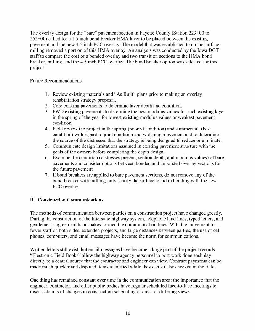
The overlay design for the “bare” pavement section in Fayette County (Station 223+00 to 252+00) called for a 1.5 inch bond breaker HMA layer to be placed between the existing pavement and the new 4.5 inch PCC overlay. The model that was established to do the surface milling removed a portion of this HMA overlay. An analysis was conducted by the Iowa DOT staff to compare the cost of a bonded overlay and two transition sections to the HMA bond breaker, milling, and the 4.5 inch PCC overlay. The bond breaker option was selected for this project.
Future Recommendations
1. Review existing materials and “As Built” plans prior to making an overlay rehabilitation strategy proposal.
2. Core existing pavements to determine layer depth and condition. 3. FWD existing pavements to determine the best modulus values for each existing layer
in the spring of the year for lowest existing modulus values or weakest pavement condition.
4. Field review the project in the spring (poorest condition) and summer/fall (best condition) with regard to joint condition and widening movement and to determine the source of the distresses that the strategy is being designed to reduce or eliminate.
5. Communicate design limitations assumed in existing pavement structure with the goals of the owners before completing the depth design.
6. Examine the condition (distresses present, section depth, and modulus values) of bare pavements and consider options between bonded and unbonded overlay sections for the future pavement.
7. If bond breakers are applied to bare pavement sections, do not remove any of the bond breaker with milling; only scarify the surface to aid in bonding with the new PCC overlay.
B. Construction Communications
The methods of communication between parties on a construction project have changed greatly. During the construction of the Interstate highway system, telephone land lines, typed letters, and gentlemen’s agreement handshakes formed the communication lines. With the movement to fewer staff on both sides, extended projects, and large distances between parties, the use of cell phones, computers, and email messages have become the norm for communications.
Written letters still exist, but email messages have become a large part of the project records. “Electronic Field Books” allow the highway agency personnel to post work done each day directly to a central source that the contractor and engineer can view. Contract payments can be made much quicker and disputed items identified while they can still be checked in the field.
One thing has remained constant over time in the communication area: the importance that the engineer, contractor, and other public bodies have regular scheduled face-to-face meetings to discuss details of changes in construction scheduling or areas of differing views.

11
Meetings may be weekly or biweekly, and they allow all parties to discuss construction and safety issues. On this project, meetings were conducted biweekly.
When a research group such as the National CP Tech Center is involved in a project, it is important to remember that the construction contract involves only the contractor and highway agency. The research team is an invited guest. In this case, it was determined that the National CP Tech Center staff would attend the project-related meetings and could offer suggestions. They could also communicate their needs to the project managers for the Iowa DOT and Manatt’s, Inc.
Any suggestions from the research team that might change the quantities or items of construction were first discussed among the research team members, then with the contractor and engineer staff on the project, and finally made in a formal suggestion to the resident construction engineer (RCE) for consideration and possible implementation. Suggestions were made in writing and submitted via email to the RCE and Manatt’s, Inc. at the same time with copies to the Iowa DOT District 2 Office.
Any questions regarding clarification of items on the plans were directed from the research team to the project manager for the Iowa DOT. Resolution of differences between the contractor, Iowa DOT staff or research team, and the Iowa DOT Central Office were directed through the RCE Office for clarification or resolution.
Communications between the contractor, Iowa DOT, and local residents were accomplished through public news releases developed by the RCE and the District Office staff. These usually involved timing for construction stages to begin and proposed road closures.
Public Input
The District Office and RCE Office also conducted a public meeting prior to the paving to alert local residents to the plan for pavement placement and curing that would result in loss of access for the curing period of 1 to 3 days. Visual displays of the paving schedule were prepared by the management team for viewing. The meeting was announced through a flyer that was hand delivered to each residence prior to the meeting. Twelve residents attended this meeting and were satisfied with the overview of the paving plan and process.
The contractor management team also contacted local residents in advance of the paving train to alert them of the temporary loss of access immediately prior to paving past their residence. Special allowances were made in the paving operation (gaps in the pavement) where access had to be maintained for special vehicles at all times. Special assistance to farmers and other residents needing access during the curing process was provided by contractor personnel and equipment.

12
Future Recommendations
1. Add a public meeting after the preconstruction conference and before work begins in the field to allow the public to interact with the Iowa DOT and contractor staff. A short presentation by the contractor on the schedule of events will identify potential local conflicts and often allow time to avert them.
2. The meeting held on this project before paving began was helpful in alerting the public as to delays and times of entrance closures that might be expected.
C. Construction Staging
This initial Iowa DOT project construction plan had six stages and centered on proposed activities in two major areas (BOP to CR W14 and CR W14 to EOP) as detailed in Table 2.
Table 2. Iowa DOT six-stage project construction plan details
Stage Description 1 Included patching, subdrains, foreslope flattening, and ditch reshaping from the BOP to
EOP and patching from the EOP to CR W14. It also included erosion control across the entire project.
2 Focused on the repair and upgrade of the approaches to each of the four bridges and the construction of transition sections and associated HMA wedges at the BOP, EOP, and on each end of the bridges. Additional intersection reconstruction work was included at the BOP/Bridge 1 and CR W14/Bridge 4. Bridge work was to be accomplished with the aid of temporary barrier rail (TBR) and traffic signals to accomplish one lane of the work and then switch traffic to accomplish the other half.
3 Required the contractor to begin base preparation (surface milling), widening preparation, pave the overlay, and associated traffic striping and shouldering from CR W14 to the EOP. At the same time, do the patching on the area from the BOP to CR W14.
4 Focused on the milling of the existing surface from the BOP to CR W14 in an effort to remove 1/2 inch of existing surface treatment.
5 Required the contractor to place the overlay from the BOP to CR W14, shoulder, and add the pavement markings in a manner identified by the owner. It also required a bonded overlay to be placed at CR V68 over the Fayette County approaches.
6 Focused on completion of the right turn lanes at CR V48 and CR W14, removal and replacement of paved entrances, and the placement of rumble strips along the length of the project.
The design team determined what items of work would be considered in each stage of the construction. Discussions during the planning phase with the representatives from industry resulted in Stages 1 and 2 being directed at clearing items of work that would impede paving. This approach allowed for paving-associated work to be done in Stages 3 through 6. Allowable working days were assigned to the project in accordance with established production rates and the staging plan.

13
The project was buildable under this staging plan. The plan addressed the staging of the various activities in each of the two project areas (BOP to CR W14 and CR W14 to the EOP) well. It would have fit in the time allotted, but required some very tight scheduling from the contractors.
There may have been an alternative way to maximize construction production and achieve the same goals as the original plans requested. It became apparent to those in the construction process that the project would require more than a simple removal of 1/2 inch of surface between the BOP and CR W14 to eliminate the wheel ruts and the existing surface course. A review of the existing surface between CR W14 and the EOP in 2011 also indicated that some value in reduced concrete-overrun and improved treatment of existing transverse joints could be achieved through milling. Finally, the location and work required at the four bridges and associated intersections made them a key critical path element in the completion of the project.
The CR W14 site was a key access to aggregates and for local commerce, as was each of the other paved routes (CR V48, V56, and V68). This project also included a very large amount of full-depth patching that was centered in the area from the BOP to CR W14.
With these factors in mind, bidders soon looked at reducing the costs of move in/move out for various subcontractors as a way to reduce costs and overlay time needs. This assessment resulted in consideration for doing erosion control installation, subdrain installation, patching, and shoulder/ditch work first. Each of these activities moves quickly and, on a project this size, can work at the same time in different areas.
This work would be followed by the bridge work. Which way the contractor chooses to pave should influence the sequence of bridge work to keep the bridge work in front of the paving operation. The bridge work can be associated with the development of the transition sections and the HMA wedges. If this project had been let in the summer as planned, rather than in the fall, all of these activities could have been done in the fall and only overlay-associated work would remain in the spring of the next year, reducing overall construction time and interactions between contract parties.
The prime contractor suggested an alternate plan of activities to achieve the Iowa DOT objectives, as summarized in Table 3.

14
Table 3. Project staging plan
Stage Description 1 Construct subdrains, patching, and drainage work across the project by beginning at the
end of project (EOP) and working westerly to the beginning of project (BOP). Two-mile work zones were used for the subdrainage and patching work that allowed for two-mile gaps between operations and an orderly construction by each subcontractor. The drainage subcontractor was able to work on the shoulders and in the side ditches to minimize conflicts between the three groups.
2 Rehabilitate the bridge approaches and railing on four bridges in the west two thirds of the project.
3 Mill the surface from the EOP westerly to the BOP in one operation. 4 Place the overlay pavement and shoulder stone from the EOP to the BOP in one
continuous operation. 5 Complete the construction of paved connections and turn lanes at three paved county
road connection. Place required rumble strips on the shoulders of the length of the pavement.
A copy of the suggested Critical Path Method (CPM) chart and proposed paving plan are shown in Appendix A.
The contractor first requested consideration of a “mill to grade” for the area of surface from the BOP to CR W14 in an effort to reduce the expected concrete overrun from 26% to 6% and assure that most of the surface treatment would be removed. The contractor also requested that the paving begin at the EOP and proceed to the west to the BOP to allow for time to work on the bridges and the proposed milling. The contractor also asked to schedule the subdrain work first, proceeding from EOP to BOP (the work was centered for just east of CR W14 to the BOP). This work was to be followed by patching the same direction.
Each of these activities required the pilot car, closed lane, and a two-mile work zone. This approach worked well for the subcontractors and only in rare instances did one have to jump past the other to have a place to work.
The grading/pipe subcontractors work did not require the pilot car, and they were able to maneuver around the subdrain and patching crews to achieve a steady rate of work.
The system described above did provide opportunities for work on one or more of the bridges during this stage of the project. The most obvious was the CR W14 intersection, which became available after the completion of patching and subdrain installation in this area.
Another option was to begin with Bridge 1 and 2 work while the other activities were at the east end of the project. The bridge work and the associated construction of transition sections create an interesting situation. The contractor must know how to work with bridge approach section removal, replacement, and concrete work for the transition sections.
15
The type of work and the non-availability of skilled personnel and equipment for this work resulted in a loss of approximately five weeks on the project.
Future Recommendations
1. Provide the contractor with a staging plan that encourages the construction of erosion control measures, subdrain installation, patching, and shoulder/ditch work at the beginning of the contract, outside the working day charge period.
2. Reduce the working day time for overlay construction in reference to work done in recommendation 1.
3. Consider ways to design the transition and bridge approach section widths and depths of pavement that encourage the use of a slipform paving machine and minimize hand pours.
4. Make timely decisions on milling questions to allow the contractor to plan this activity to follow the bridge and other preliminary work in a timely manner.
5. Consider a contract period for overlays of 5 working days per mile.
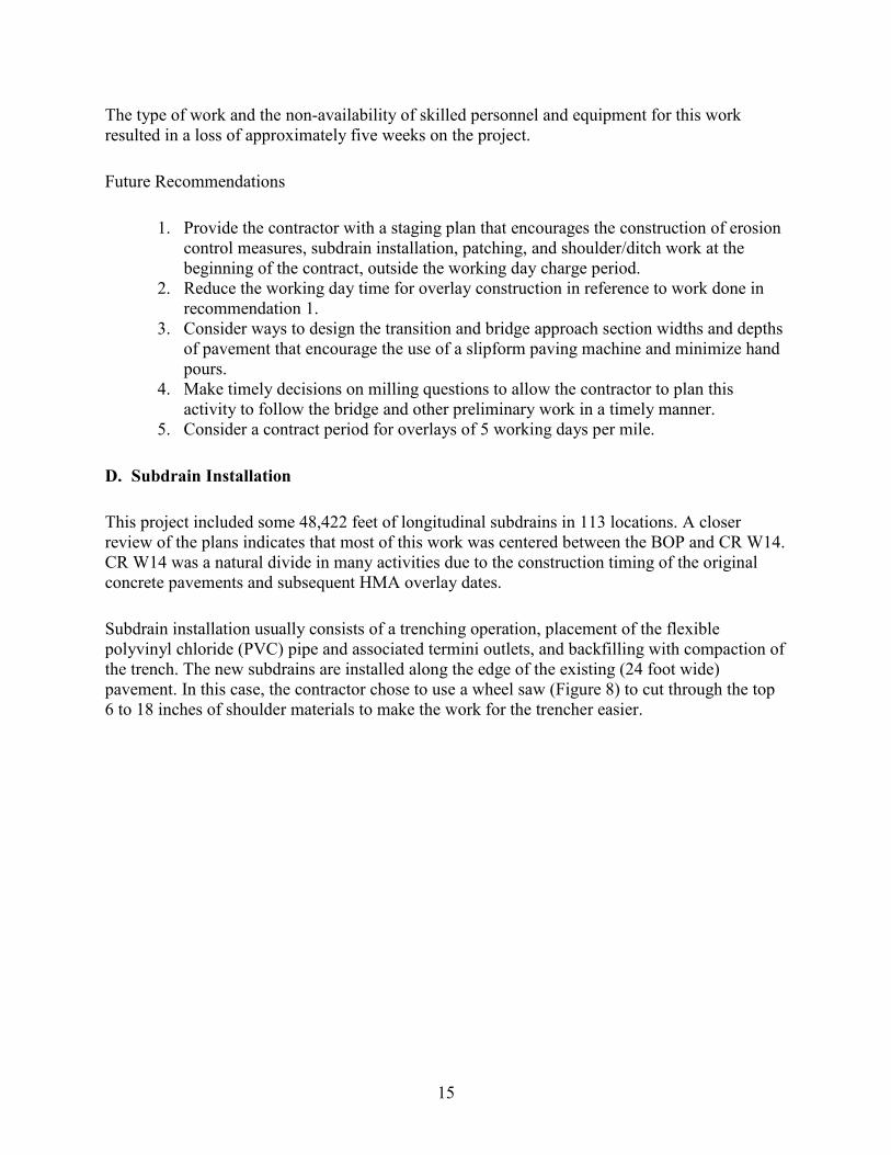
D. Subdrain Installation
This project included some 48,422 feet of longitudinal subdrains in 113 locations. A closer review of the plans indicates that most of this work was centered between the BOP and CR W14. CR W14 was a natural divide in many activities due to the construction timing of the original concrete pavements and subsequent HMA overlay dates.
Subdrain installation usually consists of a trenching operation, placement of the flexible polyvinyl chloride (PVC) pipe and associated termini outlets, and backfilling with compaction of the trench. The new subdrains are installed along the edge of the existing (24 foot wide) pavement. In this case, the contractor chose to use a wheel saw (Figure 8) to cut through the top 6 to 18 inches of shoulder materials to make the work for the trencher easier.

16
Figure 8. Wheel saw
The plans require this trench to be immediately adjacent to the existing pavement edge or widening unit on this project. It was difficult to determine where the edge of the widening unit was located due to the extra squeeze-out widths of HMA layers (Figure 9).
Figure 9. HMA squeeze-out materials
Some judgment was required on the part of field staff to hold the trench close to the existing pavement without tearing out portions of the HMA surface. Sawing an edge was ruled out due to HMA surface centerlines not always relating well to the original centerline of the underlying pavements and therefore not being usable for reference measurements.

17
In this case, the contractor used a trencher (Figure 10) to cut trench for the flexible tile.
Figure 10. Tiling trencher
A modified shouldering machine (Figure 11) placed the tile in the trench from a spool it towed, and placed the pea gravel around and over the tile. The trench material was compacted by a farm tractor with weighted wheels (Figure 11).
Figure 11. Subdrain installation
The final parts of the operation included the addition of shoulder material with a special trench fill box (Figure 12), shoulder finishing with a motor grader (Figure 13), and cleaning of the existing pavement surface with a power broom (Figure 14).

18
Figure 12. Granular backfill operation
Figure 13. Subdrain trench finishing

19
Figure 14. Power brooming
Outlets were installed with the aid of backhoes (Figure 15) for excavations of the outlet trench and skid loaders (Figure 16) to backfill the trench.
Figure 15. Subdrain outlet excavation

20
Figure 16. Subdrain outlet backfilling
The subdrain installation did require a lane closure and pilot car operation. The two-mile work zone appeared to work well. When one side of the work zone was completed, the operation and the traffic control reversed to allow work on the other side.
Subdrain installation operations can be slowed by encountering boulders in the shoulder areas. These may be the result of decisions made years ago by highway agencies as to the location for disposal of such materials or those not identified during construction of the fill shoulder areas. Removal of these boulders requires the use of a backhoe as shown in Figure 17.
Figure 17. Subdrain boulder removal

21
The original PCC pavements were often drained with longitudinal clay tile drains, located in the shoulders of the original pavements. Some have been maintained, some have been abandoned, and some have been lost in the records. The drains are usually outlets through the wing walls of small box culverts as shown in Figure 18.
Figure 18. Existing subdrain repair
With the advent of the current widening and overlay projects and associated drainage installations, these tile lines are usually showing themselves due to the location, depth, or installation equipment used for the new lines.
Future Recommendations
1. Provide a bid item note with the subdrain installation that alerts the contractor to potential subdrain repairs and pays for them by extra work order dependent on drain tile size and extent of required work.
2. Consider allowing the subdrain operation to move forward immediately adjacent to the current work as soon as traffic control is moved forward and not jump two miles to the next site.
E. Concrete Full-Depth Patching
Full-depth patch locations for the US 18 project were selected by representatives of the Iowa DOT RCE Office in New Hampton. The office suggested locations where there was severe distress along an existing transverse joint. The distresses involved cracking, heaving of the joint during the spring, and loss of surface HMA over the joint (Figure 19).

22
Figure 19. Full-depth patch area
Each of these distresses also caused a loss of ride quality. At individual joints, the Iowa DOT field staff and contractor made decisions to patch one or both lanes according to level of distress in each lane. Staff identified other full-depth patch areas where the surface crack pattern included both longitudinal and transverse cracking and loss of ride or surface material as seen in Figure 20.
Figure 20. Full-depth patch area with multiple distresses
Areas to be patched are often selected by RCE staff one to two years ahead of the construction project for design purposes and, in most cases, during non-construction seasons. When time permits, the locations and planned sizes are verified during final design and included in the plan

23
quantity tabulations. The number of patch areas and size usually increases between the first identification and the actual construction due to environmental conditions present leading up to and during construction of the overlay.
All full-depth patching begins with identification of the edges of the proposed patch to guide in the full-depth sawing of the pavement around the areas to be patched. The existing PCC/HMA concrete in the area to be patched can then be removed by breaking and removing with a backhoe or lifted from the site with aid of pins and chain hoists. In either case, the debris is loaded on trucks and hauled to a waste or recycling site on or near the project.
In the case of the US 18 project, the contractor chose to set up a two-mile work zone as per Iowa DOT specification and use a pilot car and stop signs with a flagger at each end of the work zone. Examples of these sawing and removal operations are shown in Figures 21 through 24.
Sawing was accomplished with the use of two wet saws with blades sufficient to saw 16 to 18 inches through the complete HMA/PCC pavement structure. Removal was accomplished with the use of the tractor backhoe and dump trucks and deposited off the project, but near the center of the project on private property.
This project contained 641 separate full-depth patch locations over approximately 13 of the 19 miles of pavement. The patching subcontractor targeted opening and filling 30 holes per day. This target amounted to approximately one lane-mile of patching per day. Patch areas were excavated first in the morning with the aid of two backhoes and three dump trucks.
Figure 21. Sawing around patch area

24
Figure 22. Patch area demolition
Figure 23. Patch area excavation
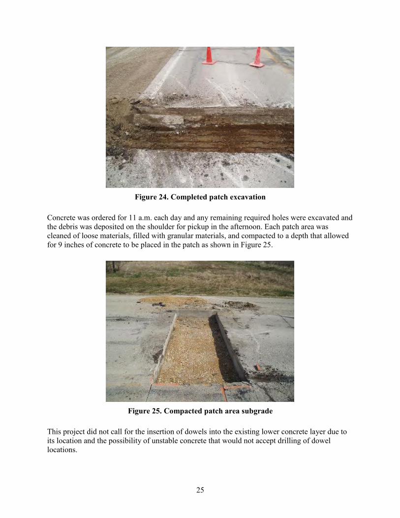
25
Figure 24. Completed patch excavation
Concrete was ordered for 11 a.m. each day and any remaining required holes were excavated and the debris was deposited on the shoulder for pickup in the afternoon. Each patch area was cleaned of loose materials, filled with granular materials, and compacted to a depth that allowed for 9 inches of concrete to be placed in the patch as shown in Figure 25.
Figure 25. Compacted patch area subgrade
This project did not call for the insertion of dowels into the existing lower concrete layer due to its location and the possibility of unstable concrete that would not accept drilling of dowel locations.

26
Concrete (M-4 mix) was delivered to the site in ready-mix trucks (Figure 26) and calcium chloride was added at the site to give as much workable time as possible to each load for placement.
Figure 26. Concrete delivery for patches
Spud vibrators were used to consolidate the concrete. Finishing was accomplished by screeding the surface in a transverse direction (Figure 27) to centerline and following the transverse profile of the pavement.
Figure 27. Full-depth patch surface finish

27
The patch was covered immediately with a layer of burlap, fiber board, and sandbags (Figure 28) at the corners to retain the heat and aid in the hydration cycle.
Figure 28. Patch curing
Afternoons were spent removing the remaining debris from the finished patches, stockpiling granular subbase for future patch locations, and sawing around patch locations for the next day. Cover for each of the completed patches was removed late in the afternoon and early enough to allow for removal of the traffic control before sunset each day.
The traffic control for this operation consisted of plastic channelizers at 100 foot spacings on centerline and a closer spacing and wedge location design at each end of the two-mile zone. Advance warning portable mounted signs warned the public of the upcoming work zone, flagger, and end of work zone (Figures 29 through 31).
In this case, the pilot car was used only during the daylight hours and all control was removed before sunset each day. When work was completed on one lane of the roadway (usually 2 days), traffic was diverted across the pavement to the completed lane and the second lane was put under construction. This approach allowed the patching contractor to complete an entire section of roadway before moving forward and reduced traffic control work time and cost.
The two-mile work zone is acceptable for this type of work. Its success is dependent on the number of patches required in the area. If the number of patches is fewer than 30, that represents one day’s work and does not allow the contractor additional area to prepare patch area sawing for the next day’s work to meet the subsequent curing time requirement. If the two-mile zone is required, the engineer should allow for a second work zone to be set up to allow for sawing the next set of patches while those in the first zone are curing in lanes one and two.

28
Figure 29. Patching traffic control
Figure 30. Patching flagger station

29
Figure 31. Patching lane delineation
Future Recommendations
1. Allow for two consecutive work zones to be located 2 miles between flagger locations rather than 2 miles between the outermost warning signs. This approach would allow for more efficient use of time and materials by both the traffic control staff and the contractor by reducing the total number of work zones that may be required on a given project where multiple subcontractors are working at the same time.
2. Where PCC full-depth patches are selected for construction, the surface of the patch should be left clean (no surface application of bituminous materials) after construction to allow for proper bonding with the proposed concrete overlay.
3. Remove the sand seal from the top of PCC full-depth patches and bond the “thin” overlay (less than 6 inches in depth) to the full-depth patch.
4. Isolate full-depth patches from the surrounding pavement in “thin” overlays with transverse joints.
5. Develop full-depth patches across from each other in adjacent lanes to remove the chance for sympathy cracking across lanes.
6. Consider the use of two work zones (separated by 2 miles) for patching type work to allow the contractor to prepare patch areas by sawing in a second zone while removal and replacement is taking place in the first zone.
7. Consider omitting the calcium chloride from the patch mix for all patches in the spring and summer and encourage the use of maturity meters at the beginning, middle, and end of the day’s patches to estimate strength. Allow opening one hour before dark, or when the strength of the patch reaches 350 psi flexural. Use the calcium chloride only when air and pavement temperatures do not support strength gain in the time between concrete placement and sunset.

30
F. Longitudinal Joint Repair Patching
In the case of the US 18 project, the longitudinal joint repair areas were located between the CR W14 intersection and the EOP. This is an area where the widening of the original PCC pavement was made with PCC. There was evidence of compression in the HMA layers over the longitudinal joint between the original pavement and the widening unit in several locations. This compression ranged in depth from 1/4 inch to greater than 1/2 inch (Figure 32).
Figure 32. Longitudinal patch area
There was some uncertainty on the part of the Iowa DOT staff as to the cause of the depression, and the decision was made to place a longitudinal patch in the affected areas. The patch was excavated using a milling machine with an 18 inch wide milling head (Figure 33).
Milling was done to a depth of the bottom of the existing HMA layer (4 to 6 inches) or the top of the original PCC pavement. In this way, the Iowa DOT could determine if the original pavement and the widening unit were separated and a void was filled with HMA or open.
All areas excavated on this project were found to have the widening and original pavement tightly bound together, and all movement appeared to be in the HMA layers due to the widening unit vertical movements during frost heave periods each year.

31
Figure 33. Longitudinal patch removal milling
The patch areas were filled with the use of a skid loader and sled that allowed HMA to flow from the truck directly into the patch area as shown in Figures 34 and 35.
Figure 34. Longitudinal patch filling device

32
Figure 35. Longitudinal patch filling
Compaction was accomplished with the use of a vibratory roller (Figure 36) and vibrating plate compactor (Figure 37).
Figure 36. Longitudinal joint vibrating roller

33
Figure 37. Longitudinal joint vibrating plate compactor
Traffic control for the longitudinal joint repairs was set up to be the same as for the full-depth patching. In this case, many of the patches were located a longer distance (500 to 1,000 feet) from the proceeding repair. It would be possible to mill, tack, and fill in a moving operation and reduce the need for traffic control to a moving operation of less than 1,000 feet each.
Future Recommendations
1. The researchers suggest that cores be taken in the areas of depressed longitudinal joints during the design phase to determine the cause of the depressions. These depressions may be such that longitudinal joint repairs will not change the situation and increasing PCC overlay depth over this area would be a greater benefit.
2. If the two-mile work zone is required with flaggers and pilot car, we suggest that the two miles be measured between the flaggers and not outermost warning signs for the reasons noted with full-depth patching.
3. Consider allowing the RCE to allow the use of a moving traffic control operation of a given distance for work such as this due to the methods the contractor suggests.
G. Miscellaneous Drainage and Grading Work
Miscellaneous drainage and grading work items on the US 18 contract dealt with extension of drainage structures (Figures 38a and 39a), addition of driveway culverts, plugging existing cross road culverts, foreslope flattening, ditch and reinforced concrete box (RCB) cleaning (Figure 38b), reattachment of culvert end sections, and preconstruction drainage tile repairs (Figures 39a, 39b, and 40).

34
Figure 38a. RCB
Figure 38b. RCB cleaning

35
Figure 39a. Culvert extension/relay
Figure 39b. Entrance pipe placement
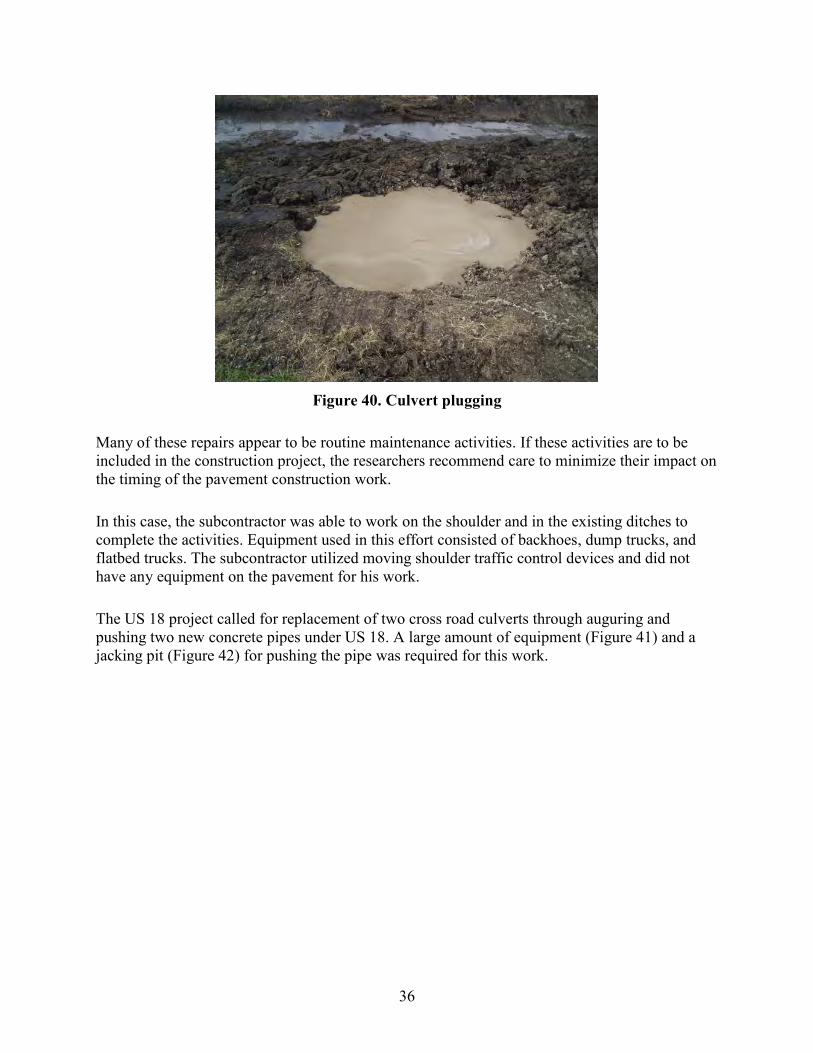
36
Figure 40. Culvert plugging
Many of these repairs appear to be routine maintenance activities. If these activities are to be included in the construction project, the researchers recommend care to minimize their impact on the timing of the pavement construction work.
In this case, the subcontractor was able to work on the shoulder and in the existing ditches to complete the activities. Equipment used in this effort consisted of backhoes, dump trucks, and flatbed trucks. The subcontractor utilized moving shoulder traffic control devices and did not have any equipment on the pavement for his work.
The US 18 project called for replacement of two cross road culverts through auguring and pushing two new concrete pipes under US 18. A large amount of equipment (Figure 41) and a jacking pit (Figure 42) for pushing the pipe was required for this work.

37
Figure 41. Culvert pushing equipment
Figure 42. Culvert pushing pit
The existing pipe appeared to be in good condition and at nearly the same flow line elevations as the proposed structures. The replacement process worked as planned with one exception. The subcontractor encountered concrete headwall from a culvert on the same location (at least one generation prior to the current culvert) and had to break through it with pneumatic drills and hammers from within the new augured hole.
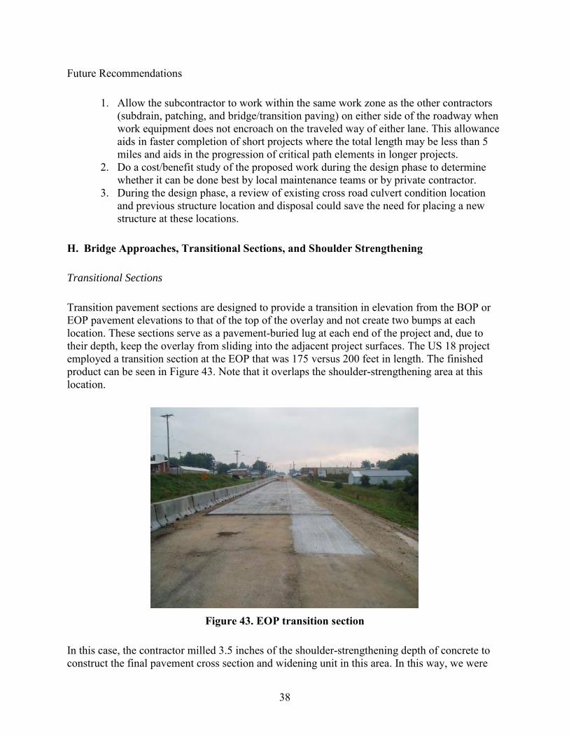
38
Future Recommendations
1. Allow the subcontractor to work within the same work zone as the other contractors (subdrain, patching, and bridge/transition paving) on either side of the roadway when work equipment does not encroach on the traveled way of either lane. This allowance aids in faster completion of short projects where the total length may be less than 5 miles and aids in the progression of critical path elements in longer projects.
2. Do a cost/benefit study of the proposed work during the design phase to determine whether it can be done best by local maintenance teams or by private contractor.
3. During the design phase, a review of existing cross road culvert condition location and previous structure location and disposal could save the need for placing a new structure at these locations.
H. Bridge Approaches, Transitional Sections, and Shoulder Strengthening
Transitional Sections
Transition pavement sections are designed to provide a transition in elevation from the BOP or EOP pavement elevations to that of the top of the overlay and not create two bumps at each location. These sections serve as a pavement-buried lug at each end of the project and, due to their depth, keep the overlay from sliding into the adjacent project surfaces. The US 18 project employed a transition section at the EOP that was 175 versus 200 feet in length. The finished product can be seen in Figure 43. Note that it overlaps the shoulder-strengthening area at this location.
Figure 43. EOP transition section
In this case, the contractor milled 3.5 inches of the shoulder-strengthening depth of concrete to construct the final pavement cross section and widening unit in this area. In this way, we were

39
able to salvage a portion of the shoulder-strengthening course and still construct the final cross section using a portion of the existing strengthening.
If the HMA alternative had been used for the shoulder strengthening, it would have been removed prior to the paving of the transition section. When PCC is used, it is important to consider transverse joint locations in the shoulder strengthening that will match those planned for the transition section.
Where the existing pavement is to be widened 4 or more feet, the shoulder widening is only needed on the side of the bridge approach or transition section that will be constructed in Stage 2 of the work. The work done in the Stage 1 will provide for the additional width through the work zone.
The transition sections were also employed at each end of a bridge within the project limits to transition from the bridge approach elevations to that of the top of the PCC overlay. In this case, the lengths were calculated to be 175 feet, including 70 feet of bridge approach section for each bridge. The second bridge on this project did not call for bridge approach repair and therefore the new portion of the transition pavement was placed at 105 feet in length. Figure 44 shows both of the new transitions at this bridge and the remaining bridge approaches on each end of the bridge.
Figure 44. Bridge transition section
Bridge Approach Sections
Bridge approach sections become a part of overlay projects when the existing pavement approach section and paving notch are in need of repair or replacement. Figures 45 and 46 illustrate the removal of the existing bridge approach and the replacement of the base materials and paving notch.

40
Figure 45. Paving notch replacement
Figure 46. Bridge approach base preparation
This work required removal of reinforced bridge approach sections, replacement of the concrete notch (ledge on the back of the abutment), and placement of both double- and single-reinforced bridge approach slabs (double-reinforced next to the bridge and single- next to the double-reinforced slab). This work also included a PCC paved shoulder along and under the inside edge of the bridge approach guardrail as shown in Figure 47.

41
Figure 47. Paved bridge shoulder
On the US 18 project, each of the four bridges required the use of a temporary concrete barrier rail through the bridge area to allow for reconstruction of one lane at a time. This type of setup is illustrated in Figure 48.
Figure 48. Temporary barrier traffic control
Shoulder Strengthening
Shoulder-strengthening sections are widening units at each corner of the bridge designed to reinforce the granular shoulders through the bridge construction area. This project required that the shoulder-strengthening sections be constructed of HMA or PCC and were scheduled to be

42
removed after the bridge work was completed and before the transition and overlay slabs were placed.
In this case, the contractor chose to use PCC widening for the 8 inch concrete depth and 6 foot width. These units were placed at the BOP, EOP, and each of the bridges, due to the rehabilitation that was required on bridge rail, guardrail, bridge end posts, and concrete approaches, and addition of transition sections of pavement. An example of the shoulder-strengthening sections in place is shown in Figure 49.
Figure 49. Shoulder strengthening in place
Lengths of shoulder strengthening were developed from the planned bridge rehabilitation activities and extend past the work area enough to permit vehicles to enter and leave the work zone on pavement. The strengthening unit was removed as shown in Figure 50 when the new transition/widening units were to be added.
This is the first such overlay project that included the bridge approach, transition, paved shoulder, and shoulder-strengthening slabs together at each bridge location. The project plan created some challenges in construction coordination, use of paving equipment, and maximum use of existing materials.
Changing paving widths created problems in the use of pavers and hand work. The issues could be averted by changing the width of bridge approach and transition pavement to that of the pavement on the mainline. The remainder of the pavement section width to the guardrail could be paved by hand after the main portion was completed and allow for faster construction of the pavement through the bridge area with improved profile control.

43
Figure 50. Pavement and shoulder strengthening removal
Future Recommendations
1. Develop a transition section length at the end of the 70 foot bridge approach section with a 1 inch rise for every 25 feet from the low point at 60 foot from the bridge end to the elevation of the PCC overlay.
2. Construct bridge approach, transition, and mainline overlays to the same width to allow slipform paving of all with one machine. Place the variable widths in the paved shoulder sections and shoulder-strengthening areas that most likely will be done by hand work.
3. If shoulder-strengthening units are planned, the units and temporary barrier rail (TBR) lengths should extend past the construction area for the combined bridge approach/transition sections. Where the units extend past the transition areas, they should be jointed in the same spacing on each side of the road as the overlay that will be placed in this area. In place of removal and replacement with the overlay widening unit, the units can be milled to the depth of the overlay and replaced with the overlay concrete and tie bar configuration.
4. Where bridge approach slabs are to be replaced, the length of transition should include the bridge approach slab length where possible to reduce the overall length of the transition section. Two other considerations to apply in the development of the transition length include the ability to drain water away from the bridge where possible along the roadway (minimum of the bridge approach distance) and assist in the development of a minimum length of vertical curve approach of 300 feet to the bridge deck.
5. Layout of new bridge approach slabs and transitions should be accomplished in conjunction with the development of the roadway profile pavement gradeline by the contractor. The layout can be accomplished with conventional stringline or stringless surveying techniques.

44
6. Omit the construction of the shoulder strengthening on the side of the bridge or transition section that will be built in Stage 2 of the work.
I. Surface Surveys
The following method was used to develop the control system for the overlay of US 18:
A. The Iowa DOT provided the following:
a. X and Y coordinates and stations for the key points on centerline of the existing road to include Points on Tangents, Beginning of Curvature, Point of Intersection, End of Curvature. Each of these points was located by the use of the Iowa Real-Time Network (RTN) system and global positioning system (GPS) equipment.
b. X and Y coordinates on all existing land section corners and quarter corners within the roadway using the Iowa RTN system and GPS equipment.
c. X, Y, and Z coordinates of benchmarks along the route (1 to 2 mile distance between points) and the control points at 1,000 foot intervals along the project. The Iowa DOT staff placed steel rods (40 inches long) in the north foreslope at approximately 1,000 foot intervals. They established a GPS “project network” by referencing the control points and existing benchmarks to known survey markers in the county near the project. These points have been established by precise survey methods under separate contract to the counties in the area.
The Iowa DOT staff used GPS survey equipment and the RTN system to establish new X, Y, and Z coordinates on each of the control points and benchmarks along the project. This method forms a “project-level” set of coordinates, X, Y, and Z, for use between the BOP and EOP that are all relative in coordinates to each other. The coordinates can be checked against accuracy on X and Y at any point. This GPS coordinate system forms the basis for the project construction coordinate system. In most cases, these elevations will check very closely with the U.S. Geological Survey (USGS) elevations on known benchmarks along the route.
B. Control set by contract surveyor:
a. Using the Iowa RTN, the surveyor places intermediate control points at 250 foot intervals on alternate sides of the roadway along the project between the Iowa DOT 1,000 foot control points (Figures 51 and 52). These are metal pins, usually 4 feet long and driven below the frost line for stability. The control points can be placed anywhere in the right of way that is visible. They are most often placed in the fore or backslopes of the roadway. Care must be taken when the pins are placed in the foreslope to assure they are protected against damage from a haul road or shoulder construction.

45
b. Using a GPS pole and handheld data collection device connected to the Iowa RTN, the surveyor verifies the X, Y, and Z coordinates of each Iowa DOT point and establishes the coordinates of the new intermediate control points.
Figure 51. Marked survey control point
Figure 52. Control point cap
The original contract documents for the project called for a 1/2 inch depth of milling across the pavement surface in the area from the BOP to CR W14. This milling plan was designed to remove the 1/2 inch of existing surface treatment that was determined to be a problem for bonding the new overlay adequately to the existing surface. It assumed an overrun of 15% in

46
concrete material quantity to allow for concrete used in the wheel ruts and for the excess slope at the outside edges of the pavement.
During the preconstruction project conference, the contractor asked the Iowa DOT to consider allowing the milling of the entire surface in this area to a predetermined centerline grade and cross slope rather than the 1/2 inch nominal centerline cut and 2% cross slope. The contractor noted that the 1/2 inch nominal cut would not reach the bottom of the wheel ruts and that the cross slope exceeded 2% in many places, which would result in an absence of milled area on the outside edges of the pavement.
In addition, the contractor felt that the expected overrun in yield in the concrete overlay material could be reduced from double digits of 16 to 26% (main slab to main slab plus widening) to single digits of 2 to 6% for the main slab and widening units combined. The contractor asked for this milling to be considered as a Value Engineering item on the contract.
The project management staff (contractor, Iowa DOT RCE staff, and the National CP Tech Center) discussed the proposal and the pros and cons several times during the summer. During that time, some field observations also became part of the decision-making process.
The existing widening units tend to move vertically over the course of the year due to the environment. HMA or PCC widening is not tied to the original pavement and lacks the mass to move in the same way the main pavement moves. This situation results in the widening units being tilted up on the outside edges during the winter and spring when the ground is saturated and tilted down during the summer months. The situation creates a hinge point at the joint between the original PCC pavement and the two widening units (existing and under construction) that must be considered in rehabilitation design and construction for future performance.
Additional areas of concern extended from CR W14 to the EOP as a result of transverse joint distress noted in this area during the spring thaw period of 2011. Many of the joints tended to “tent up,” creating a bump and indicating some deterioration in the lower layers. These joints are a concern to the performance of thin PCC overlays due to the HMA point acting to reduce the thickness of the PCC overlay, and create a vertical plane of weakness. Milling of these areas is one way to improve the long-term potential of PCC overlay performance.
These discussions resulted in the decision to do an in-depth survey of one mile of the existing pavement surface mapping to determine the following:
Recommended longitudinal interval between cross sections Recommended number of survey shots across the pavement to identify all points that
could influence the concrete yield Impact of detailed surveys on estimated concrete yields

47
The National CP Tech Center member was asked to identify one mile of roadway that would serve as a representative section for a test mile of survey. That mile extended from T Avenue, easterly to the CR W14 intersection. An extra work order was written for the work to include the field survey, development of a profile grade, and calculations of estimated concrete yield.
Survey cross sections were taken at 25 foot intervals and at nine locations across the slab (two edges, four wheel paths, two quarter points, and one centerline) for the entire mile. The layout is shown graphically in Figure 53.
Figure 53. Cross-section survey points
One other limitation was placed on the test mile by the National CP Tech Center staff. The depth of removal at centerline was limited from a minimum of 1/2 inch (Iowa DOT plan) to 1.5 inches. The design of the overlay assumed an existing HMA depth of 6 inches with a minimum of 4 inches remaining to be part of the structure for the final design.
No coring had been performed to verify HMA layer thicknesses across the pavement or along the length of the project. Minimum length of vertical curves for the milling profile was limited to 100 feet to assure the best chance for the best ride values in the final surface.
The modeling consultant used the Iowa DOT 1/2 inch nominal centerline cut and 2% cross slope as the base line for comparing alternatives. The consultant considered alternative calculations that included 1/2 inch or profile grade milling at centerline in conjunction with survey combinations of 3, 5, and 9 shot cross sections and intervals of 25 or 50 feet. The best fit for this project was the use of 9 shot cross sections at 50 foot intervals in conjunction with a contractor-determined milling centerline profile. The alternatives resulted in a reduction of estimated concrete yield for the entire cross section from 26 to 6% or less.

48
The surveying and modeling effort used on this project helped the Iowa DOT evaluate the costs and benefits of various surveying frequencies on the final concrete quantities and costs. In this case, the effort provided enough potential savings that the Iowa DOT could increase the overlay depth from 4.0 to 4.5 inches and retain additional project savings.
The Iowa DOT was assured the 4.5 inch overlay depth across the pavement cross section and could visually see where the additional concrete was being added to strengthen areas in the wheel paths. “Milling to grade” gave the contractor a more precise estimate of required concrete materials and an opportunity to share in the contract savings in concrete with the owner.
This approach also provided the contractor with an increased volume of millings that could be used or sold to others. Furthermore, the uniform depth of overlay provides for better management of concrete curing and joint development time for management of sawing crews and prevention of premature cracking.
Milling of the entire project surface provided the best potential for bonding between the existing HMA and PCC overlay.
Future Recommendations
1. In the design phase, consider two options for development of the PCC material quantities: a. Add 20% to a theoretical quantity and do no preliminary survey work other than
measuring wheel rut depths and cross slope at 500 foot intervals along the pavement length. Measurements should be taken in the summer months to eliminate the environment effect on widening units. This survey will prove an “estimate only” of existing conditions at the time of the survey to compare to a 20% addition in quantity. If this amount is added to the contract, utilize the Minnesota specifications and limit the contractor to staying within 2% of this estimated quantity. Do not allow for surface milling except to provide for scarification or specific identified locations by the RCE.
b. If the goal of the project is to minimize concrete yield, require the contract surveyor to survey, at a minimum, the entire project at 50 foot intervals and 9 shot cross sections. The contractor should develop a centerline profile that limits removal based on the assumptions made by the pavement designer for remaining layer condition and depths. In this case, the target yield value for concrete quantity can be set at 6% plus or minus 2% for construction tolerances.
2. Investigate other ways of mapping the existing pavement surface prior to development of the finished grades for centerline and edges of pavement overlay that assure the nominal overlay depth will be maintained at centerline, and pavement quarter points and edges.

49
J. Surface Preparation for Overlays
The decision on when and what to do in the way of surface preparation should be made in the design phase. Surface preparation can be modified in the construction phase if the assumptions used in the overlay depth design are communicated between the design and field office staff.
The goals of the surface preparation usually center on the following:
Need for removal of unstable surface layers Need to provide vertical clearance at key locations along the route Need to maintain a final centerline and shoulder elevation profile grade to meet
funding and safety requirements Need for an adequate existing surface to bond with the PCC overlay
In most cases, a clean HMA surface will provide adequate bonding capability for PCC overlays. In the case of thin overlays on HMA that appears to have excessive asphalt cement in the surface layer, bonding may be difficult in summer months. The answer can be to scarify or rough the surface to provide small depressions for bonding of the PCC.
If the surface of the HMA is irregular or contains unstable layers, consideration should be given to removal of enough of the surface area to provide for a bonding surface at the centerline and pavement edges. This approach will help ensure that bonding is developed and retained in the wheel paths even though some of the existing HMA is still exposed.
The decision to not mill, scarify, or mill to a grade should be made based on the four surface preparation goals shown above and two goals related to the construction.
First, milling of the existing surface improves the potential for better ride values in the finished product. With this approach, better ride values are achieved through the removal of irregularities in the existing surface that create uneven depths of overlay at transverse joints and over wheel paths and widening units. Uniform depth of PCC aids in curing time reduction, improved sawing window timing, and final ride values.
The second goal to be considered in the milling decision at construction relates to the agency goals in concrete overlay yield. If concrete yield is the key goal of construction, milling can reduce over runs to 6% or less in addition to the benefits outlined in the previous paragraph.
The milling decision should be made by the design staff (Road Design and Pavement Design) in conjunction with representatives of the District and RCE offices. In this way, the decision should be based on all available knowledge of pavement condition and assumptions that have been made in the design process. The decision can be modified at the time of construction if all parties understand what the requested change has on the overlay design anticipated performance.

50
Milling decisions were made on this project based on the information noted above. There is room for improvement in communications between the pavement designers and the District/RCE offices in regards to the layer assumptions used in the original overlay design.
The information exchange and intensive one-mile survey could have been done in the spring months to expedite the decision on both sides and provide the contractor with one more way to expedite the project.
Lessons learned on this project should allow these decisions to be completed within 30 days of their initiation with the RCE office.
Initial observations taken during construction on this project point to some noted benefits from the milling of the surface of this project:
Ability to achieve uniform overlay depths and minimize concrete overruns. The average concrete overrun on the mainline paving was 104%.
Improved ride values. The combination of three things contributed to this observation. The first was the milling of the existing surface to a uniform grade and cross slope. The use of the stringless paving method of slipform control and the employment of real-time profilers on the wet concrete immediately behind the slipform each aided the contractor in achieving very good ride values. The values far surpassed those found without the noted milling and slipform machine modifications.
This contract specified that the contractor was responsible for the maintenance of the milled surface until it was covered by the PCC overlay. Contract language required the contractor to begin paving soon after the milling was underway. Any milled surface not covered with the overlay at a seasonal shutdown was required to receive an HMA overlay that would be placed and removed the next season at the contractor cost. Milling was allowed to proceed from the EOP westerly to a point selected by the contractor for an intermediate stop. The contractor milled to within 2.5 miles of the BOP.
Milling was accomplished with the use of a large milling machine (shown in Figure 54) that contained a 7 foot wide head. The machine fed a fleet of 5+ trucks, depending on the distance from the stockpile site (Figure 55) located one mile north and a half mile west of the Hawkeye corner (CR W14 and US 18).
The machine made a first pass along the centerline and in the westbound lane (WBL) under the control of the total stations (Figure 56) and the paving model. This trip usually proceeded at 25 to 30 feet per minute due to the limited ability of the computer to match profile and cross slope rapidly.
The milling machine was able to travel at 1 to 3 mph on the second pass in the same lane, without the total station control, by matching the elevation of the edge of the first pass and continuing the 2% cross slope.

51
The final products can be seen in Figure 57 of the milled surface and concrete patch and in Figure 58 where the mill left existing surfaces due to excessive ruts or cross slopes. Similar speeds were achieved in the opposing lane passes using the centerline elevation profile and the given 2% cross slope.
Figure 54. Milling to grade, pass #1
Figure 55. HMA millings stockpile

52
Figure 56. Total station mill control
Figure 57. Milled PCC full-depth patch

53
Figure 58. Irregular milled surface
Milling of wheel rutted pavements to an established grade can expose HMA layer delaminating in two ways. As a given depth of HMA is removed, it can expose layer interfaces within the HMA that are weak and spall out under construction traffic. At the same time, milling off the high points at centerline, quarter points, and pavement edges can expose ragged edges between these points and the lower rutted areas that can spall under the construction traffic. Neither of these occurred in this case and the HMA-milled surface remained intact, stable, and durable during overlay construction.
If the HMA had spalled during overlay construction, the contract called for replacement of the HMA. This change in the existing pavement surface elevations, in turn, would have required a survey to assure the design depth of PCC could be maintained over the replacement HMA. Experience has shown that fresh HMA is also difficult to bond to PCC layers.
Future Recommendations
1. Emphasize the need for communication within the highway agency design and construction staff during design and prior to construction to understand the overlay design assumptions and limitations in milling question considerations.
2. The contracting agency should consider coring HMA layers throughout the area under milling consideration to assure that an adequate depth of HMA will remain when the milling is complete to meet PCC overlay design assumptions.
3. Consider the following goals in determining the type and amount of existing surface preparation: a. Need for removal of unstable surface layers b. Need to provide vertical clearance at key locations along the route c. Need to maintain a final centerline and shoulder elevation profile grade/cross
slopes to meet funding and safety requirements

54
d. Need for an adequate existing surface to bond with the PCC overlay e. Need to minimize concrete overrun values (and consider the recommendations
shown in item J) f. Need to maximize surface ride values
K. Pavement Widening
Currently, the Iowa DOT design calls for one of three overlay/widening scenarios. Assuming an existing 24 foot wide pavement, the overlay may be of the existing pavement only without widening, widening of 2 foot on each side (28 foot total roadway), and widening of 4 foot on each side (32 foot total roadway) of a two-lane roadway.
The widening unit of PCC is usually determined to be 8 inches in depth (below the finished edge of pavement grade). Depending on the final centerline profile grade and cross slope, the amount of cut for the trench can range from 0 to 8 minus the overlay depth inches on average. The widening can also result in a fill of either PCC or granular material requirement if the 8 inch depth is to be maintained in the widening unit on tangent or super-elevated curve sections.
The use of the field surveys of cross slope and rut depths discussed in the previous section can aid the designer in preliminary identification of the areas of cut and fill associated with the formation of the widening unit. It is difficult to compact granular material to the required depths for fill in these cases. The researchers suggest that missing material be replaced with PCC in the design for best overlay performance.
Specifications and plan notes on this project allowed the contractor to cut the trench with a motor grader type device or other equipment of choice. The plans also called for the edge between the existing pavement and trench to be near vertical as possible and clean of loose materials. Minimal dislodging of HMA materials was also desired from the remaining HMA structure at the pavement edges.
The contractor began to form the trench at the EOP, working westward with a motor grader blade, and experienced problems in developing a vertical edge in the HMA and not tearing large chunks of HMA from the remaining surface due to the weathered nature of the material. Where the blade could rub against the existing PCC widening unit and the existing HMA unit did not extend over the edge of that widening, the removal resulted in limited success. Vertical control of the 3.5 inches of trench depth was maintained with a sonic sensor on the end of the blade and over the existing pavement edge.
Due to the limited success with the blade method, the contractor was asked and chose to consider a milling machine. Given this project had existing shoulder widths of 8 to 10 feet, the contractor chose to bring in a milling machine with a 7 foot wide head (Figure 59) for the trenching.
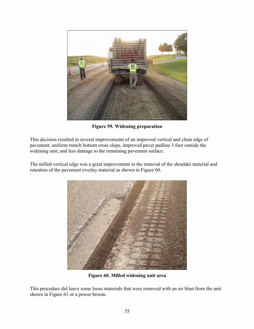
55
Figure 59. Widening preparation
This decision resulted in several improvements of an improved vertical and clean edge of pavement, uniform trench bottom cross slope, improved paver padline 3 foot outside the widening unit, and less damage to the remaining pavement surface.
The milled vertical edge was a great improvement in the removal of the shoulder material and retention of the pavement overlay material as shown in Figure 60.
Figure 60. Milled widening unit area
This procedure did leave some loose materials that were removed with an air blast from the unit shown in Figure 61 or a power broom.

56
Figure 61. Widening edge cleaning
A motor grader shown in Figure 62 moved the remains from the milling to a width of approximately 7.5 feet from the existing pavement to allow for a padline for the slipform paver.
Figure 62. Slipform padline preparation
The finished widening unit area can be seen in Figure 63 with the tie bars in place.

57
Figure 63. Widening final joint
The management group of this project focused on reducing the overrun in the concrete quantity. The contractor utilized the “milling to centerline grade” and maintaining a 2% cross slope to establish a paving surface.
In most cases, this procedure resulted in a milled surface at the pavement edges. This surface elevation results in a reference plane for milling the widening to the required depth (8 inches below the final top of pavement grade). If milling of the entire pavement surface had not been done, the equipment would have been referenced to the proposed centerline final grade elevations and required a stringline or stringless control system to maintain milling depths.
Existing shoulders on this project were often found to be lower than the pavement edge by 2 or more inches and at a slope greater than per plan. This situation resulted in a lack of material to cut with the blade or milling machinery. Existing shoulder stone was moved in from the outside edges, water was added, and the surface was compacted to form a platform for the widening unit.
Trying to add an additional widening unit to an existing one can result in problems identifying the original widening outside edge. In the westerly portion of this project, the HMA overlays added width to the surface with each overlay and slight changes in centerline alignment. This situation resulted in an “over hanging” edge of HMA that may extend 2 to 4 inches past the widening unit and be 2 to 6 inches deep. It would be difficult to identify in the design phase, but is usually first seen during subdrain trenching operations.
If the motor grader blade is used to cut the new widening trench, this type of area will result in large pieces of surface HMA being torn out or a weak joint system at the area between the two widening units. The use of the milling machine and its weight enabled the formation of a straight vertical edge and being able to better locate the edge of the existing pavement widening unit below.

58
The wide existing shoulders on this project allowed the contractor to stockpile much of the excess widening trench millings along the outer shoulder as shown in Figure 64.
Figure 64. Shoulder material stockpile
The contractor then pulled this material up to the edge of the pavement within hours of the paving to protect the area from erosion in a rain and provide drainage to allow for shouldering to begin as soon as maturity was reached in the pavement.
Future Recommendations
1. Suggest in the contract plans that the widening trench be cut with equipment that can provide a vertical edge at the existing pavement that is equal to or better than that provided by a milling machine.
2. Identify in the plans how much trench depth, if any, will be required on the high side of super-elevated curve areas.
3. Clarify the width of the existing pavement lane that will be used as a reference for location of the widening unit to begin. The goal is to butt the new widening against the existing widening unit.
4. Operate the shoulder trench miller from the same model as the mainline pavement milling and paving to reduce the overrun in shoulder concrete and effectively build an 8 inch thick widening unit.
5. Suggest milling the surface of the existing pavement widening unit and the proposed widening unit to a depth of 8 inches.

59
L. Pavement Overlay Paving Plan
A proposed paving plan was included in the US 18 plan set. The plan was included as part of the final staging plan in Stages 3 and 5. The plan centered on Fayette County CR W14. Paving began at milepost (MP) 260, moved westerly in the westbound lane WBL to CR W14, returned in the eastbound lane (EBL) to the EOP, and then westerly to the point of beginning. Stage 5 centered on the Chickasaw/Fayette county line and completed a similar circle of paving between the BOP and CR W14.
In the planning efforts, this was seen as a workable plan that allowed the contractor to pave for approximately 5 days in one direction, gain maturity over the weekend, turn around and pave the next week. This plan met some paving goals and minimized the movement of the paving equipment, but did not account for the shouldering operations. The plan assumed the widened pavement section would be delineated with channelizers on both sides and shouldering/marking would be done when both lanes were completed.
The contractor proposed a different plan that essentially began paving at the EOP and paved westerly. A copy is shown in Appendix A. Paving would be done within the allotted 3.5 mile work zone in the WBL in a westerly direction. Assuming maturity was reached in 18 to 30 hours after paving, shouldering would be following and allow for the paving train to move back at the end of 3 days and begin paving westerly in the EBL on approximately day 5, after all shouldering was complete. The contractor would then continue to pave for 3 days, wait for shouldering and pavement marking, and then move forward another 3.5 miles in the EBL. At that time, the equipment would be moved back to the WBL end of paving and the process would be repeated until paving reached the BOP.
Future Recommendations
1. Require the contractor to develop the paving plan that meets the project and contractor needs. The plan should consider efficiency in operations and use of people and equipment, the concrete delivery plan, material source locations and access to the plant, access from shoulder material sources to the completed work areas, public travel disruption, and local crossing access.
2. The contractor plan should be evaluated on its ability to deliver the completed pavement, shoulders and markings in the least amount of time and interference with the traveling and local public.
3. The application of the 3.5 mile work zone limit is adequate for this work. 4. Plans should allow for more than one paving work zone at a time to make efficient
use of contractor resources and time.

60
M. Construction
Preparations for paving of this type require some thought and different techniques from that of full-depth paving on new grade. On this project, the following operations took place prior to paving a lane:
1. Milling of the shoulder area to provide an area for the widening unit and a padline. 2. Power sweeping of the existing paving surface. 3. Air blasting of the vertical edge of the existing pavement. 4. Placement of the tie bars across the existing widening unit and extending 18 inches
into the new widening unit and the original pavement area. 5. Air blasting of the pavement area ahead of the paver on the day of paving.
Milling of the widening trench has been previously discussed in this report. The power sweeping at this time allows removal of any remaining materials from the milling operation or loose particles from traffic use of the pavement. The addition of the air blast shown in previous figures will remove any remaining HMA that is partially bonded to the existing surface and provide a clean vertical surface at the pavement edge.
During the course of the project, the National CP Tech Center staff made a suggestion to isolate the concrete patches with transverse joints. This suggestion also required tie bars to not be closer than 6 inches from the edges of the patches. This suggestion did require special tie bar locations in each patch dependent on the length of the patch and on the adjacent pavement area. The 30 inch spacing was maintained in the patch areas and in the areas adjacent to the patches. Transverse joint patterns were maintained across both lanes even when patches occur only in one lane.
Number 5 tie bars, 5 and 6 feet in length (dependent on existing widening unit width) were placed on 30 inch centers along the roadway edge. The location of each bar was determined by the use of the wheel shown in Figure 65 that was calibrated in diameter to paint a dot every 30 inches. A similar wheel with circumference equal to the transverse joint spacing was used to mark a dot in the open lane for the joint identification process after the cure cart.

61
Figure 65. Tie bar location device
The bars were also marked with paint at 18 inches from the outside end to allow for fast placement on the ground. The bars were attached to the existing HMA with 1.5 inch nail/clips and by HILTI guns as illustrated in Figure 66.
Figure 66. Tie bar installation
The plans required a minimum of three clips per bar. The management team agreed to apply two clips behind each bar on the pavement side of the bar and one ahead of the bar near the edge of the pavement as seen in Figure 67.

62
Figure 67. Tie bar clip layout
This method was designed to reduce the chance for turning of the bar by the concrete head in front of the paver. This method worked very well. This operation required a crew of 5 to 8 to stay ahead of the paving operation. To aid in this operation, the contractor automated the placement of the clips with the unit shown in Figure 68 to reduce back problems. The equipment could also be used for the nailing operation that followed.
Figure 68. Tie bar clip automation
The project plans included a special note that a stringline could not be used at centerline of the roadway. This approach was designed to reduce the width of the slipform paver and associated equipment into the open traffic lane. In this way, the pilot car and through traffic could use the
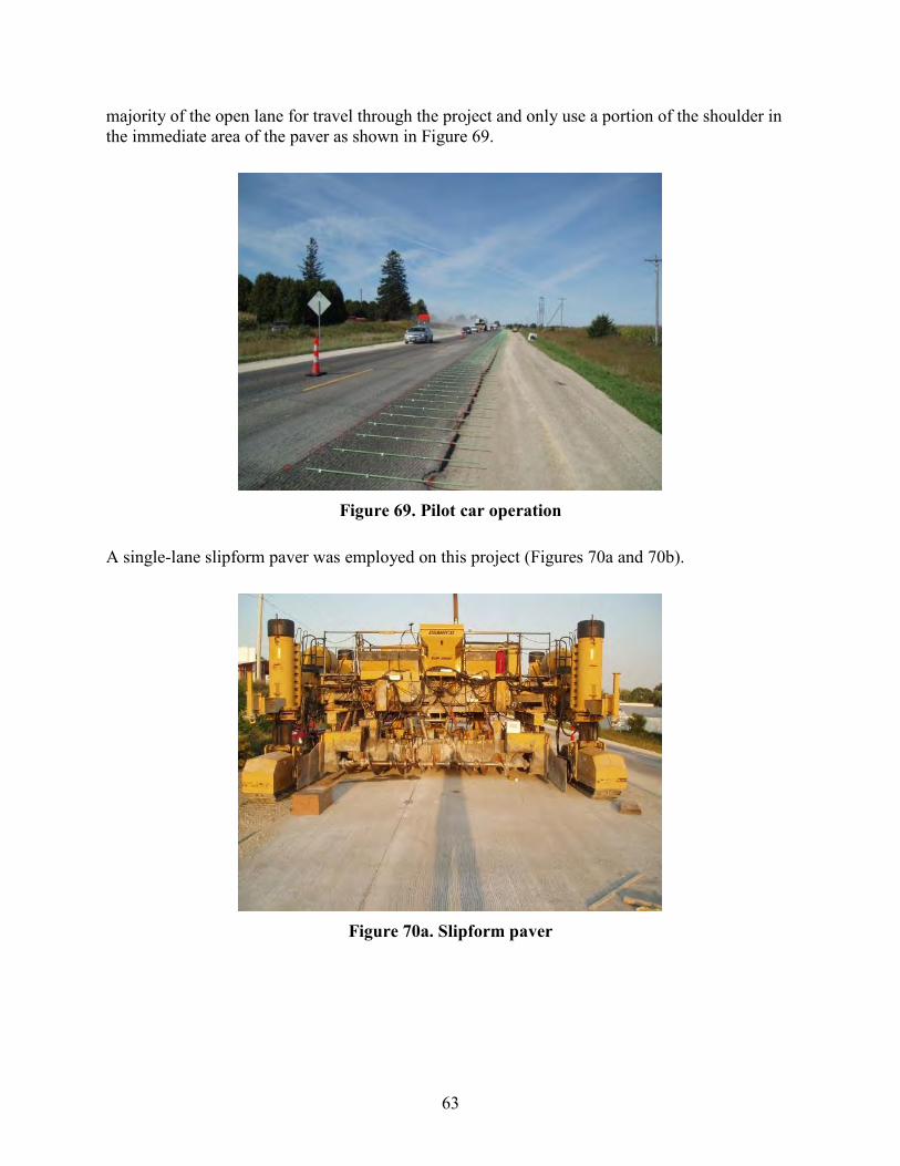
63
majority of the open lane for travel through the project and only use a portion of the shoulder in the immediate area of the paver as shown in Figure 69.
Figure 69. Pilot car operation
A single-lane slipform paver was employed on this project (Figures 70a and 70b).
Figure 70a. Slipform paver

64
Figure 70b. Slipform paver burlap drag
The paving train included the slipform, workbridge with burlap drag (Figure 71), and a cure/texture machine (Figure 72).
Figure 71. Workbridge and burlap drag

65
Figure 72. Cure/texture machine
Without the use of stringlines, the cure/texture machine employed the use of a vertical and horizontal wheel shown in Figure 73 to track the pavement surface for guidance and elevation for texturing.
Figure 73. Cure/texture machine guidance control
The slipform paver on this project had some unique features that assisted the crew in achieving stringless paving and a very good surface ride quality. To meet the stringless need, a LEICA system was used to both guide the machine and control the elevation of the finished product. The control system operates from two total robotics stations (Figure 74) of known location and

66
elevation at any given time and references the slipform to a contractor-developed three-dimensional (3D) model.
Figure 74. Robotic total station
In this case, the same model was used to direct the surface milling operations for location, depth, and cross slope. Indirectly, this approach set the initial pavement profile and smoothness values also. The model is contained in an on board computer (Figure 75) that references the total stations through a radio communication system shown on the leg of the total station in Figure 74.
Figure 75. Stringless paver controller
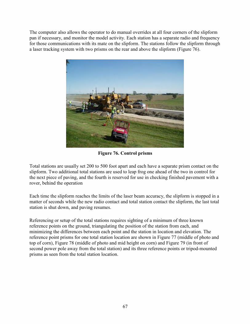
67
The computer also allows the operator to do manual overrides at all four corners of the slipform pan if necessary, and monitor the model activity. Each station has a separate radio and frequency for those communications with its mate on the slipform. The stations follow the slipform through a laser tracking system with two prisms on the rear and above the slipform (Figure 76).
Figure 76. Control prisms
Total stations are usually set 200 to 500 foot apart and each have a separate prism contact on the slipform. Two additional total stations are used to leap frog one ahead of the two in control for the next piece of paving, and the fourth is reserved for use in checking finished pavement with a rover, behind the operation
Each time the slipform reaches the limits of the laser beam accuracy, the slipform is stopped in a matter of seconds while the new radio contact and total station contact the slipform, the last total station is shut down, and paving resumes.
Referencing or setup of the total stations requires sighting of a minimum of three known reference points on the ground, triangulating the position of the station from each, and minimizing the differences between each point and the station in location and elevation. The reference point prisms for one total station location are shown in Figure 77 (middle of photo and top of corn), Figure 78 (middle of photo and mid height on corn) and Figure 79 (in front of second power pole away from the total station) and its three reference points or tripod-mounted prisms as seen from the total station location.

68
Figure 77. Prism 1 Site (middle of photo)
Figure 78. Prism 2 Site (middle of photo)

69
Figure 79. Prism 3 Site (near second power pole)
On this project, the reference points were approximately 250 feet apart longitudinally and located near the ROW line rather than in the highway shoulder, to minimize potential for damage. This approach created some visibility problems in the fall of the year and flags were attached to the tripods to make them easy to spot in the total station telescope. The use of all-terrain vehicles such as the one shown in Figure 80 made access to the points quick and easy.
Figure 80. Stringless survey crew vehicles
Total stations are sensitive to low sun angles in the spring and fall as they interfere with the line of site between the slipform and the total station. This situation is only momentary and simple
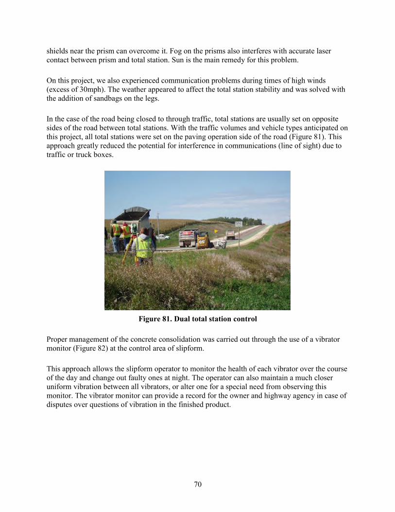
70
shields near the prism can overcome it. Fog on the prisms also interferes with accurate laser contact between prism and total station. Sun is the main remedy for this problem.
On this project, we also experienced communication problems during times of high winds (excess of 30mph). The weather appeared to affect the total station stability and was solved with the addition of sandbags on the legs.
In the case of the road being closed to through traffic, total stations are usually set on opposite sides of the road between total stations. With the traffic volumes and vehicle types anticipated on this project, all total stations were set on the paving operation side of the road (Figure 81). This approach greatly reduced the potential for interference in communications (line of sight) due to traffic or truck boxes.
Figure 81. Dual total station control
Proper management of the concrete consolidation was carried out through the use of a vibrator monitor (Figure 82) at the control area of slipform.
This approach allows the slipform operator to monitor the health of each vibrator over the course of the day and change out faulty ones at night. The operator can also maintain a much closer uniform vibration between all vibrators, or alter one for a special need from observing this monitor. The vibrator monitor can provide a record for the owner and highway agency in case of disputes over questions of vibration in the finished product.
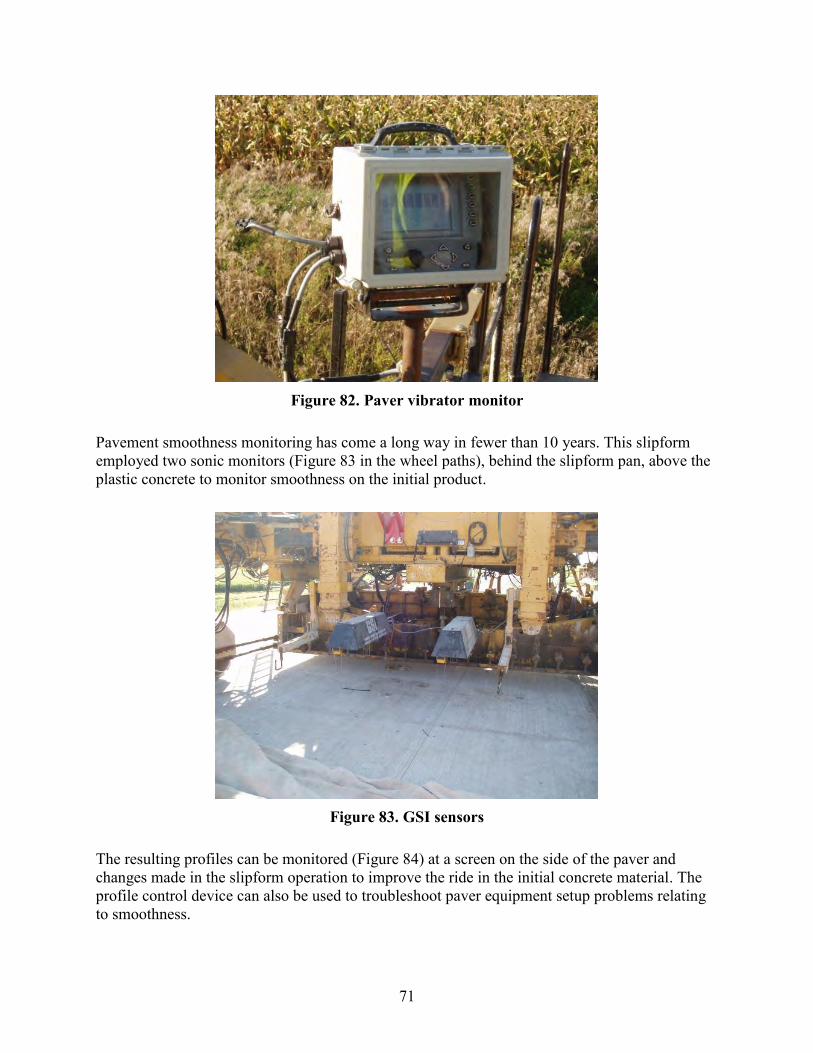
71
Figure 82. Paver vibrator monitor
Pavement smoothness monitoring has come a long way in fewer than 10 years. This slipform employed two sonic monitors (Figure 83 in the wheel paths), behind the slipform pan, above the plastic concrete to monitor smoothness on the initial product.
Figure 83. GSI sensors
The resulting profiles can be monitored (Figure 84) at a screen on the side of the paver and changes made in the slipform operation to improve the ride in the initial concrete material. The profile control device can also be used to troubleshoot paver equipment setup problems relating to smoothness.

72
Figure 84. GSI monitor
The slipform paver was fed by a fleet of 18 to 20 dump trucks hauling 8 cubic yards of concrete each. The portable drum mix plant used on this project (Figure 85) provided a load of concrete every two minutes. This plant cycle time became the main control on production at the paving site.
Figure 85. Central mix concrete batch plant
The contractor was able to maintain a rate of 15 to 18 feet per minute of forward movement for the project and many days of 8,000+ feet of single-lane pavement and widening for most production days.

73
The number of trucks required was driven by the nearly 15 mile haul and the traffic control requirements. Trucks were not allowed to pass the flagger stations. Specifications required the load to be deposited within 30 minutes of production.
Through the use of a double dose of water reducing agent, the mix was allowed 45 minutes to be placed and the contractor was able to meet that specification. In most cases, there were between one and four trucks in front of the paver at any time during the day. Construction proceeded from sunrise to sunset 5 to 7 days per week.
Iowa DOT specifications provide for the establishment of a system of haul routes from material sources to the concrete plant, concrete from the plant to the construction site, and other material routes to the project that involve the use of local roads. The contractor is asked to submit a list of proposed routes as part of the preconstruction conference materials. The Iowa DOT is the approval authority in consultation with local road authorities. Project funds are used to reimburse local government agencies for local road damage attributed to the primary road construction.
The prime contractor requested a list of haul routes for this project that included almost all north-south roads crossing US 18 in the project limits and east-west routes one mile north and south of the project. The routes were deemed necessary to assure the timely (45 minute) delivery and placement of concrete for the overlay at various points between the EOP and BOP. The Iowa DOT staff approved the routes that are shown in in Appendix B.
Some of the requested routes were unavailable due to local bridges with load limits below that required for the concrete delivery trucks. The approved system allowed the contractor to cross US 18, use a southerly route on county roads to travel easterly and north to enter the project within the work zones and avoid lost time waiting at the flagger/pilot car stations. Insufficient local bridge load ratings were the reason for this set of routes.
For the westerly portion of the project, concrete traveled easterly on local roads one mile north of US 18 and entered the work zone inside the flagger stations. In the case of paving at each end of the project, loaded and empty trucks used existing or overlaid portions of US 18 as much as possible to reduce travel time and local road wear.
The decision of constructing an overlay of this type, one lane at a time, can carry with it an additional responsibility of the contracting authority for designation of additional haul routes and greater compensation to local road authorizes for haul road wear due to construction.
When stringless paving is specified, the general reference system for the cure/texture cart (sting line) is removed also. Although total stations can be used to guide this machine, the costs and time make it impractical to use on a cure cart or concrete belt placer.
Instead, Iowa contractors have adopted a simple set of wheels shown earlier in this report to sense the edge and top of pavement that works very well. Care was taken with this machine to assure white-pigmented cure was sufficiently applied to the pavement surface and pavement
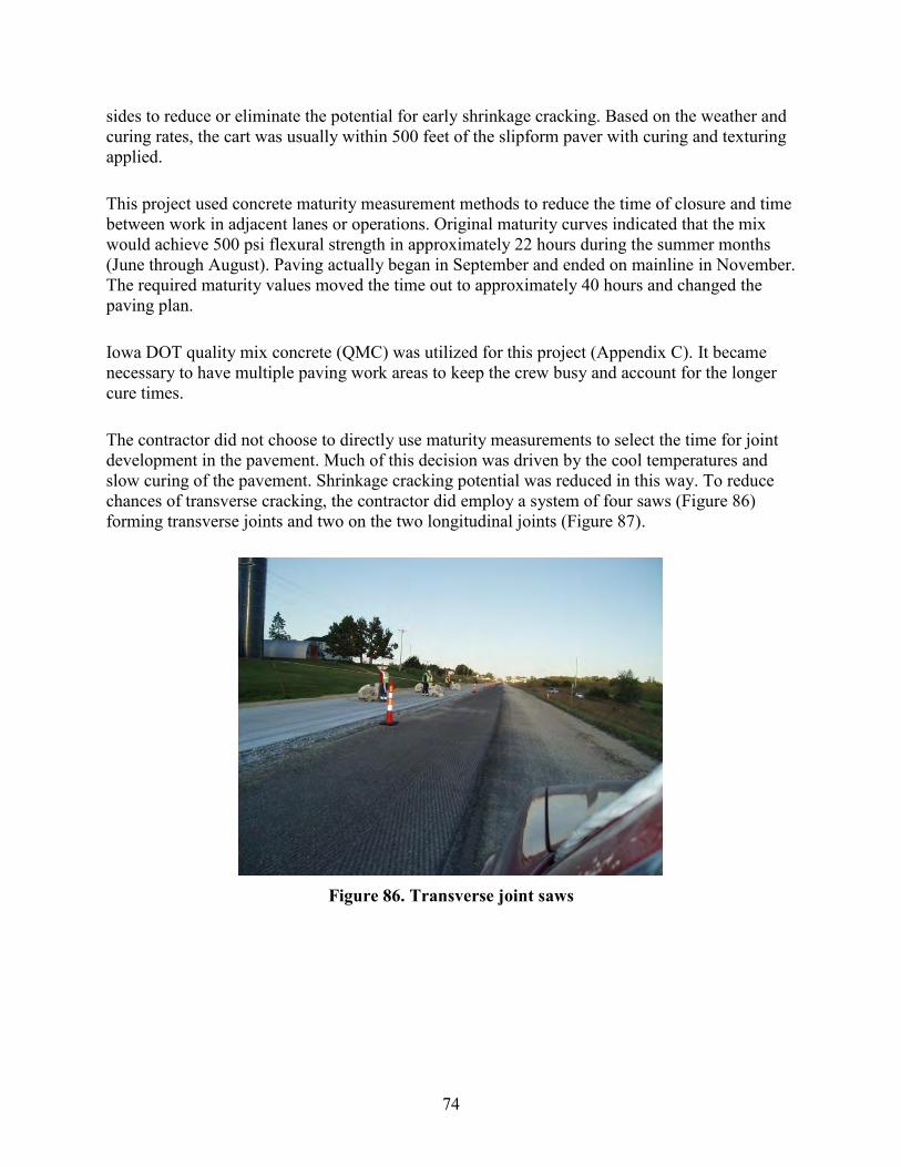
74
sides to reduce or eliminate the potential for early shrinkage cracking. Based on the weather and curing rates, the cart was usually within 500 feet of the slipform paver with curing and texturing applied.
This project used concrete maturity measurement methods to reduce the time of closure and time between work in adjacent lanes or operations. Original maturity curves indicated that the mix would achieve 500 psi flexural strength in approximately 22 hours during the summer months (June through August). Paving actually began in September and ended on mainline in November. The required maturity values moved the time out to approximately 40 hours and changed the paving plan.
Iowa DOT quality mix concrete (QMC) was utilized for this project (Appendix C). It became necessary to have multiple paving work areas to keep the crew busy and account for the longer cure times.
The contractor did not choose to directly use maturity measurements to select the time for joint development in the pavement. Much of this decision was driven by the cool temperatures and slow curing of the pavement. Shrinkage cracking potential was reduced in this way. To reduce chances of transverse cracking, the contractor did employ a system of four saws (Figure 86) forming transverse joints and two on the two longitudinal joints (Figure 87).
Figure 86. Transverse joint saws

75
Figure 87. Longitudinal joint saws
Each of the transverse saw crew members worked on a set of five joints in succession and then moved out in front of the other members and cut another set of five joints. This worked well under the weather conditions. Often on overlays, another solution, which was used on this project, is for one saw to be sent forward to saw every fifth joint and then have the other saws fill in the remaining joint cuts. The idea is to not let the pavement cure out ahead of the saw crew and cut control joints at every fifth joint location. The process is usually referred to as “skip” sawing to reduce random cracking.
Each of the four transverse joint saw crew members worked on a set of five joints in succession. This process meant that the first member began on joint 1, the second on joint 6, the third on joint 11, and the fourth on joint 16. As each person finished their group of five joints, they moved ahead of the other members and began another group of five joints. In this way, every fifth joint was being cut initially to reduce the chance for premature transverse cracking in the pavement.
An alternative way used by other contractors in this situation is to send the first transverse joint saw person out to cut joints 1, 6, 11, 16, etc. in increments of 5 joints to achieve the early control joint concept. The remaining intermediate joints are then cut by the additional saw crew members in consecutive cuts by the number of additional saws being used for this purpose.
The two longitudinal joint locations were developed by removing the cure cart tines (2 to 3) from the joint areas and then operating the saw guide over the edge of the tine mark on one side of the open area. This technique works well when the cure/texture cart has a good longitudinal guidance system.

76
Future Recommendations
1. Require the contractor to have maturity recording devices that allow for a continuous set of values. This requirement can aid the contractor in bad weather conditions and provide a more accurate record in cases of dispute over joint development and opening times.
2. Consider maturity measurements as a trigger value for sawing in hot weather conditions where concrete placed in early morning, noon, and late evening cures at different rates.
3. Allow for additional haul road designations and local compensation to provide for raw material and concrete delivery throughout the project when the project is constructed by single lane under pilot car and flagger traffic control.
N. Traffic Control Solutions During Project Construction
A traffic control plan for this project was included in the staging plan. A summary of the traffic control solutions in each stage are shown in Table 4.
Table 4. Iowa DOT six-stage traffic control plan summary
Stage Summary 1 Maintain traffic through the project using work zones with pilot cars. Work area between
CR W14 and EOP. 2 Maintain traffic through the project using TBR and temporary signals. Close CR
connections as necessary. Work area between CR W14 and EOP (paving) and four bridge sites
3 Maintain traffic through the project using work zones and pilot cars. Work area between CR W14 and EOP (complete paving) and begin pavement preparation between the BOP and CR W14.
4 Maintain traffic through the project from BOP to CR W14 and the completed section from CR W14 to the EOP. Work included milling of the existing pavement surface from the BOP to CR W14.
5 Maintain traffic through the project from BOP to CR W14 with 24 hour pilot car. Close CR connections as necessary. Work included paving of overlay from BOP to CR W14.
6 Maintain traffic through the project. Work included construction of right turn lanes, driveways and rumble strips.
The traffic control plan laid out by the designers was workable and would have provided the desired final product. The plan did require several mobilizations by subcontractors to meet that schedule.
The paving plan laid out by the contractor changed the construction process and provided an alternative method of construction. Essentially, the plan provided for all major construction processes, such as subdrains, patching, milling, and paving, to begin on one end and proceed from the EOP westerly to the BOP. To make this plan work meant that the contractor had to

77
begin with the reconstruction of the CR W14 intersection and bridge work as soon as possible and work each of the other bridges in a westerly direction after CR W14.
There could have been at least one other plan identified for this project. Given the aggregate sources and plant site were located in the middle of the project, work could have begun on the major items at the ends and proceeded toward the middle of the project. This plan would have worked well until two or more operations got within the 2 mile work zone limit of each other and then the plan would have reduced the options for work.
The Iowa DOT plan also called for the use of 42 inch high channelizers to separate the single lane of construction and the through traffic lane with pilot car (Figure 88).
Figure 88. Lane channelizers
In addition, as the first lane was paved, a centerline safety wedge was required to be built along the edge of the new slab. The centerline safety wedge was to be 1 inch below the top of the overlay at centerline, 1 foot in width, and have a 1 inch height at the outside edge of the fillet. The construction method was left to the contractor with the approval of the engineer.
The wedge was required because the height of the overlay exceeded 2 inches and was a potential problem for errant vehicles driving across the slab (intersections or driveways) or not following the pilot car in the assigned lane. The same traffic control plan called for the wedge to be continuous and remain in place until construction of the adjacent lane was being prepared. In many cases, this meant a performance life of 2 to 3 days at maximum.
The contractor designed a sled-type device and connection to the back of the slipform paver to form the centerline wedge as shown in Figures 89 and 90.

78
Figure 89. Centerline safety wedge slipform
Figure 90. Centerline safety wedge extrusion gate
The sled consisted of a rectangular box with flared sideboards that contained a single vibrator and an end gate shaped at the desired fillet cross slope. The sled was built so it could be bolted to either rear corner of the slipform and secured across the slipform to keep it vertical. Concrete was obtained from the front of the slipform with the use of a skid loader (Figures 91 and 92) and deposited into the box as the slipform moved forward.
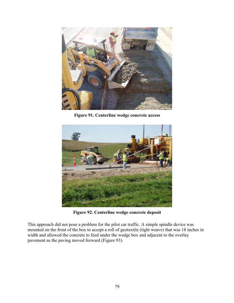
79
Figure 91. Centerline wedge concrete access
Figure 92. Centerline wedge concrete deposit
This approach did not pose a problem for the pilot car traffic. A simple spindle device was mounted on the front of the box to accept a roll of geotextile (tight weave) that was 18 inches in width and allowed the concrete to feed under the wedge box and adjacent to the overlay pavement as the paving moved forward (Figure 93).
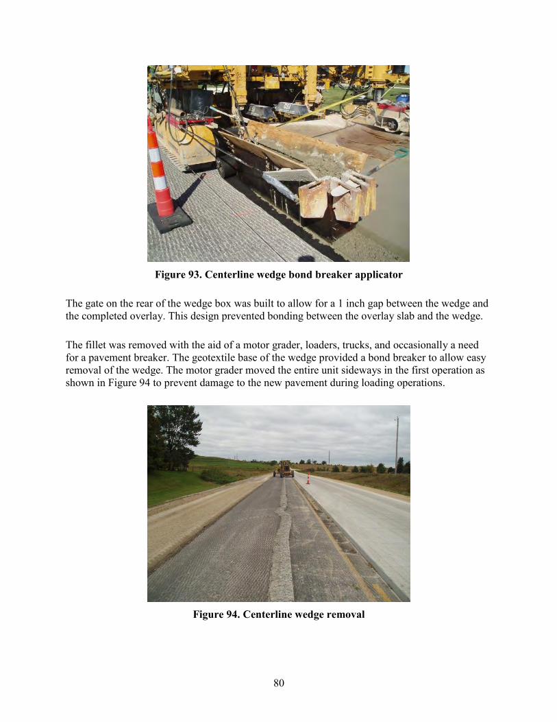
80
Figure 93. Centerline wedge bond breaker applicator
The gate on the rear of the wedge box was built to allow for a 1 inch gap between the wedge and the completed overlay. This design prevented bonding between the overlay slab and the wedge.
The fillet was removed with the aid of a motor grader, loaders, trucks, and occasionally a need for a pavement breaker. The geotextile base of the wedge provided a bond breaker to allow easy removal of the wedge. The motor grader moved the entire unit sideways in the first operation as shown in Figure 94 to prevent damage to the new pavement during loading operations.
Figure 94. Centerline wedge removal

81
A skid loader and bucket loader (Figure 95) provided gathered the materials and loaded them for removal from the site. The disposal area was located near the middle of the project.
Figure 95. Centerline wedge removal loaders
In areas where the geotextile bond breaker did not get under the unit, a pavement breaker was required to remove the fillet. Removal of 3.5 miles of fillet could be accomplished in one day with the aid of four trucks, skid loader, motor grader, end loader, and pavement breaker.
Centerline safety wedge construction was accomplished, but at a cost in time and materials that does not seem reasonable under the project circumstances. This particular project only allowed traffic to follow the pilot car at speeds of up to 35 mph through the area where the fillet was constructed. Side roads were closed in this area during this part of the construction and persons living on the newly paved portion of the road were not allowed to use it or cross it until concrete opening strength had been obtained. The pilot car kept personal vehicles on the unfinished side of the roadway. Driveways were reconstructed with granular materials when the shouldering was being completed and even then the traffic was allowed to only follow the pilot car.
In general, the traffic control plans worked to deliver the project on time. Some items can be improved. The work zones for subdrain, patching, and miscellaneous work off the pavement were controlled with portable signs and were able to move with the operations. Subcontractors worked well together and allowed the required 2 mile gap between flagger warning signs under the pilot car operations. The work zones also followed each other across the project, which reduced the number of potential congestion points in overlapping work areas. This approach will allow for more simultaneous operations to occur in projects like this one or in ones that are only 5 miles total in length.

82
Traffic signals and the use of the TBR worked well at the west three bridges. The bridges and transition work at the BOP (Figure 96) utilized the traffic signals and TBR to provide movement from side road CR V48 and through traffic on US 18.
Figure 96. BOP Bridge #1 traffic control
The TBR was long enough to allow for construction of the bridge approach slabs and transition paving (Figure 97) to be placed at the same time, reducing cost and time of construction. The same can be said for the two bridges in the center of the project.
Figure 97. Bridge #1 EBL transition

83
The problem bridge rehabilitation came at CR W14. In this case, the intersection was immediately adjacent to the bridge. Two bridge approaches and one intersection were to be replaced. Two transition slabs and one turn lane were to be added. In this case, the standard 520 foot maximum TBR length plus ends did not allow the contractor to work on one half of the area at a time. This situation essentially resulted in four TBR setups (one per bridge corner).
This location was a major traffic artery for Fayette County and turned out to be a chokepoint for construction. The route was also the only access for shoulder stone for much of the project due to a series of substandard bridges near the source.
A large concern of the public in both counties was the closure of many adjacent county access roads at the same time. The project contains paved roads at CR V56 (Chickasaw County) and CRs V68 and W14 in Fayette County. The paved CRs subdivide the project into four pieces of relatively the same size.
During this construction, at times, two or three of these major roads were closed to through traffic at the same time. This situation resulted in some unhappy local residents and drivers trying to move across the project and developing some interesting detours around barricades and road closures. An alternative paving construction plan and traffic control plan suggested by local residents was as follows:
1. Close US 18 from CR W14 to the EOP and detour through traffic on Fayette County gravel roads around this area. Require the contractor to pave full width in this area and complete all work prior to moving to the next section.
2. Open US 18 from the EOP to CR W14 and close it from CR W14 to CR V68. Use county roads for the through traffic detour. Require the contractor to pave US 18 full width in this area and complete all work prior to moving to the next section.
3. Open US 18 from CR W14 to CR V68 and close it from CR V68 to CR V56. Use county roads for the through traffic detour. Require the contractor to pave US 18 full width in this area and complete all work prior to moving to the next section.
4. Open US 18 from CR V68 to CR V56 and close from CR V56 to the BOP. Use county roads for the through traffic detour. Require the contractor to pave US 18 full width in this area and complete the project.
5. Open all of US 18 to through traffic.
This method can reduce construction time and construction wear on the local roads and retain local road maximum use.
At the end of each 3.5 miles of single-lane paving, the contractor was asked to place an HMA runout (Figure 98).

84
Figure 98. HMA runout
This runout was to act as a “temporary transition” between the finished overlay and the unfinished, milled surface. The same runout was required at the ends of the transition sections, if the runouts were placed prior to the overlay in connecting the overlay to the end of the project or a bridge section. This transition was completed at each of the noted locations on this project in accordance with the plans.
This detail is a very good one for situations where the runout will stay in place over a series of months such as a winter shutdown or a prolonged delay in construction. In the case of the US 18 project, the runouts were used for an average of less than one month at the ends of the project and 7 days for the normal 3.5 mile paving work zones.
The subcontractor placed the runouts when the first lane was paved and removed them when the second lane was paved 7.0 miles and a new runout was placed at the end of that work area. This work requires a different subcontractor to place the runout materials and must conform to their time schedule. The researchers recommend giving considerations to allowing alternative runout lengths and materials for situations that are not expected to be in existence for less than one month. This lane is under pilot car control in the normal paving work areas and at a maximum of 35 mph versus highway speeds.
Given this was the first official PCC overlay being built under traffic, monitoring of traffic volumes and delay time at work zones was a major concern. This particular section of highway had a permanent recorder embedded in the existing pavement in the easterly portion of the project. The recorder continued to record data daily from the start of the construction on April 1 through mid-August when the milling operation rendered the traffic loops inoperable.

85
Data collection actually began April 11 and ended on July 31, 2011. Comparison of data from March 2011 to April 2011 indicated an approximate 10% drop in average daily traffic (ADT) with the beginning of construction. This decrease left the overall ADT at 2009 in April and the traffic rose to 2,392 in June and leveled out at 2,317 in July.
The percentage split of vehicles only changed from 85% cars versus 15% trucks to 86% cars versus 14% trucks throughout the construction time period. There appeared to be no change in the number of large vehicles using the route as the combo vehicle portion of the trucks remained at 9% throughout the construction period. The delay time at each work zone averaged 12 to 15 minutes per round trip at the 35 mph speed limit of the pilot car. The use of two work zones did not change the volume of cars or trucks in the project area.
Future Recommendations
1. Encourage the contractor to build bridge approaches and transition sections prior to or staged with the items such as subdrains, patching and earthwork.
2. Delete the construction of the centerline safety fillet in pilot car operation areas and only one lane of the roadway is open for traffic to follow the pilot car.
3. Provide plan notes that allow the contractor to use multiple work zone setups simultaneously as allowed by plan and project limits. This allowance will assist the traffic control contractor planning.
4. Allow work by equipment on the shoulders across the road from a lane closure to proceed at the same time as the lane closure operation.
5. Reduce the distance required between work zones to 2 miles between flagger stations versus the current 2 miles between outermost warning signs.
6. Keep the 3.5 mile length for paving work zones. Allow the contractor to close local road crossings in a work zone only when those in the adjacent one are open to traffic.
7. Allow and encourage the use of three leg signal operations and extended TBR lengths in locations where bridges and intersection reconstruction are adjacent, to reduce overall construction time and traffic disruption.
8. Encourage the use of the lane paving, shoulder construction and pavement marking process used on this project before allowing paving of the adjacent lane or moving traffic control forward.
9. Continue the use of the HMA runout shown on plate 7308 for all situations that will result in its use for more than one month in duration.
10. Allow the contractor to suggest alternative materials that provide a 6 feet per1 inch of overlay depth, slope in runout for locations that will be temporary in nature (less than one month). Materials may include PCC over a geotextile bond breaker, compacted millings, recycled plastic materials, or other materials approved by the engineer. Payment shall be lump sum for each installation. Maintenance of the materials shall be incidental and include the installation and removal of the material.
11. Employ split barricades one mile each way from the project to alert heavy equipment of road closures. The post-mounted signs on this project did not communicate the closure.
12. Add an advisory sign at each end of the project to warn drivers of traffic delays such as Road Construction Next ____ Miles, Expect Traffic Delays.

86
13. Consider the use of portable signs versus post-mounted for traffic work zones to aid in flexibility of work sites.
14. Consider a clearance behind the TBR at bridge repair and transition construction sites of the width of pavement plus 4 feet on each side to allow for slipform paver operation.
15. Consider the application of three approach traffic signal systems where bridge work and intersection reconstruction involve one common work site and paved local roads.
16. Omit the construction of the centerline safety wedge where traffic is maintained in only one lane with the use of the pilot car on a 24/7 hour basis.
PLANNING, DESIGN, AND CONSTRUCTION LESSONS LEARNED
A. Project Selection and Construction Project Planning
Project Selection
Project selection is done by the District Office based on some deficiency in ride and/or distresses in the surface such as joint tenting or depression, widening separation, or cracking of the surface (longitudinal or transverse). This project illustrated the need to conduct field testing and visit the site more than once in the overlay design phase.
This pavement exhibited widening units that turned up at the outside edge in the spring and down in the summer. The pavement had transverse joints that “tented up” in the spring noting loss of aggregate interlock in the spring and “flat” in the summer after the subgrade dried out. Both conditions contribute to the decision on milling or not milling based on the condition of the joints.
Removal of the “tenting” should remove excess materials from the joints and provide a uniform platform for the overlay. If the transverse joints are “turned down,” the plans should provide for instructions on filling them with sand or bituminous slurry prior to paving to prevent keying of the overlay into these joints.
Surveying joints at two separate times of the year also improves the identification of full-depth patch areas. The use of full-depth PCC patches in this composite pavement identified some concerns for the future.
First, a transverse joint patch should extend across the full pavement width (not one lane) with a continuous width through the length of the patch. This approach becomes important in the development of the joint pattern for the overlay.
Second, adjustments must be made in the transverse joints on both sides of the patch to allow the patch to move freely vertically and not create a very small overlay panel on one side of the patch, which will fail quickly to its aspect ratio.

87
Traffic Constraints
Feedback from those outside of Iowa who are considering this type of work gave us direction on what might be the limits of its application. The reviewers saw this as a good alternative for two-lane roads with up to 5,000 to 8,000 ADT. Routes with ADTs greater than these values are also usually four-lane facilities. Reviewers of this project indicated they would then consider this type of work with “head to head” traffic on two lanes in one direction and paving in the other two. Truck traffic is a factor also, but the overlay construction process should be determined based on ADT.
Overlay Design Plans
We have progressed a long way from the first thin, unbonded overlay plans of 17 years ago on Iowa 21. The current plans for this project included the following improvements:
1. Addition of transition sections to accommodate the changes in elevations at bridges and project termini. This addition, coupled with joint layout considerations in the overlay adjacent to the transition section, should improve the performance of the overlay where it meets a structure or end of project section.
2. Tie steel lengths that bridge the existing widening units and extend 18 inches into the original pavement area and 18 inches into the new widening.
3. Stapling of the tie bars has now proved that the use of a minimum of three staples and a pattern of two behind and one in front of the bar will minimize the movement of the bars by the slipform paver during paving.
4. The surface preparation for widening units is best developed by the use of a milling machine.
5. Centerline and survey control information including elevations developed from three wire level circuits are included in the plans for the aid of the contract surveyor. Survey control points are usually found in the shoulder of the existing roadbed. The widening of existing roadways makes these vulnerable to construction equipment. Contractors are moving intermediate points to the backslope for more stability and ease of site during construction.
6. Stringless paving has proved itself in both allowance for overlay construction under traffic, improved ride control, and ease of construction.
7. The inclusion of the plan/profile sheets can aid the modeler in having a starting point for a profile of the new surface. The plan/profile sheets could also be evaluated by the owner to consider additional concrete depth as a way to remove some lengths of “no passing” zones in relatively flat terrain.
Plan items we can improve upon include the following:
Review of traffic control plans to remove unneeded items such as centerline safety wedges where traffic is limited to one lane and a pilot car 24/7 through the work zone.

88
Allowance for the contractor to propose an alternative runout (plate 7308) at the end of work zone in the overlay with materials, slopes, and lengths dependent on the estimated time of use and the speed of the vehicles using the runout.
Consider layouts of concrete for bridge approaches, shoulder widening, and shoulder concrete through bridge sites and allow for one width of slipform to pave all of these units in one pass on each lane.
Evaluation of “bare pavement” areas for retention “as is” rather than adding both a bond breaker and PCC overlay.
Evaluation of “inlay versus overlay” options for work through intersections with PCC paved approaches on local roads that are in very good condition.
B. Overlay Depth Design
We have learned that it is important to do coring and FWD work (spring of year) prior to design and to identify distress types, amounts, and severities in the existing pavement. Consult “As Built” plans for expected depths and material types. Cores will verify this information. It is important to know the uniformity in the base layers, their material characteristics and deformities, such as layer delaminations, prior to designing an overlay thickness. These measures also can be used in the discussion on the benefits and costs of considering milling the existing surface to a specified depth and its ramifications on the resulting PCC overlay depth needs.
C. Construction Project Description
The description of the project and the work to be done was sufficient to meet the needs of the contract. Since this was the first of its kind in traffic control, the pre-bid meeting with potential contractors was beneficial to both the industry and owner personnel.
D. Construction Communications
The RCE and prime contractor did a good job communicating with residents along the road at a public meeting prior to the beginning of milling/paving. Notification was accomplished with flyers in the door of each individual resident along the project. Twelve people attended this meeting. During paving, the contractor personally contacted residents in advance of the paving to explain the sequence of events that would take place.
We were fortunate there were only 1 to 2 businesses along the route that were impacted by paving and no cities inside the project limits. Based on work done in Odebolt, Iowa on a similar overlay project with the city in the middle of the project, additional benefits can be gained from holding a public meeting prior to any construction.
Invitations for a “public” preconstruction meeting should be sent to those residences and cities along the project, and those towns on intersecting paving highways within 10 miles of the project. The meeting should be conducted by the prime contractor staff at or near the project site

89
at a public location. Representatives of the RCE and County Engineer Offices should be present to answer any questions directed to them.
The objective of this meeting is for the contractor to lay out their construction schedule for local residents. The forum provides an opportunity to identify potential construction conflicts in scheduling and to work out solutions. The meeting also acts to clarify the time and extent of proposed road closures and their impact on surrounding communities.
E. Construction Staging
This project identified some potential for change in construction staging on the plans. The Iowa DOT did a great job of setting up a staging plan with the pre-paving items placed in the early stages of the project and the paving at the end. The existing plan worked well to include the miscellaneous grading and drainage, sub drainage, and longitudinal and full-depth patching in Stage 1 for the complete project.
This approach provides for the best and most economical use of the contractor forces and for continuous operations across the project in this case. For example, the contractor was able to start the sub drainage, full-depth patching, and miscellaneous subcontractors simultaneously at different locations and reduce the overall time required for all three operations.
One of the original thoughts of the National CP Tech Center staff was to look at ways to precast bridge approach sections of the site during the winter, prior to construction, and reduce the time of delay in the reconstruction of such sections in the field. This project identified reasons why precast units would not be practical on many projects.
Each of the four bridges on the project was relatively small, but non-standard in construction or items identified for rehabilitation on this project. Some needed bridge railing rehabilitation, end-section connection changes, paving notch replacement, and non-standard approach shape replacement. In addition, each needed to be connected to the overlay through the addition of a transition paving section.
It appears that the transition sections and bridge approach section replacements fit well in a Stage 2 that prepares the bridges and approaches and the ends of the project to receive the overlay in advance of other work. The bridge work could be scheduled in the fall of the year prior to paving along with the other Stage 1 work to reduce the overall time of construction of the overlay. This schedule will require the use of longer TBR installations to accommodate bridge approach, transition, and shoulder-strengthening sections to be built. The plan will reduce the length of shoulder strengthening required in these areas to one side only. With some knowledge of the bridge width, the operation can be scheduled to allow for the use of a slipform paver to construct the transitions and bridge approaches in one operation on each lane of the bridge and create an improved section and ride value.

90
The staging of the paving can be developed by the pavement owner, but should be open to consideration of plans by the contractor that might shorten the overall project construction time or make for more efficient use of existing road networks in the execution of the paving plan.
The contracting authority must consider the limits of milling options and allowable depths in the approval of a paving plan. Where milling was considered on this project, changes were made to improve the removal of the existing surface and to create a savings in overall concrete overlay quantity requirements. Although it would be hard to prove, this decision also contributes to a better overall ride value in the surface.
F. Subdrain Installation
The methods used to specify and construct the subdrains on this project worked well. The traffic control length of 2 miles worked well and the subcontractor was able to move rapidly across the project. In many cases, the subcontractor was able to get both sides of a 2 mile section done in the same day.
Given the amount of subdrain required on any project is highly variable in quantity and location, no changes are suggested in this area of the plans. Contractors have developed their own specialized equipment and methods to make this an efficient and speedy operation.
The use of a wheel rock saw by the contractor did aid the operation in loosening the shoulder material to speed up the operation of the trencher that followed.
G. Concrete Full-Depth Patching
This project contained a large amount of full-depth patching. This resulted in a large number of patches in each 2 mile work zone. The contractor was able to optimize this effort with a target of filling 30 holes per day and having time to prepare for the next day in the same zone and lane or opposing lane. This operation moved steadily from the EOP to the BOP and encountered only one time where there was a conflict in work zones with other subcontractor efforts.
The researchers suggest to Iowa DOT personnel marking for PCC full-depth patches that they consider marking the patches completely across the pavement width and at the same width of patch. This procedure allows for the proper joint spacing to be continued in the overlay to match the patch and surrounding pavement overlay.
The saw, remove, replace subbase and concrete methods specified in Iowa appear to work well. The bottom of all patch excavations in this project turned out to be “dry.” The plans called for compacted modified subbase up to a remaining depth of 9 inches in each hole.
Work done in 2001 for the Iowa DOT on Hickman Road in West Des Moines proved that PCC could be substituted for modified subbase in the patch and save time and preparation. This

91
additional mass of concrete could also assist in maintaining the patch surface elevation during and after construction.
There has been a concern about drainage of the PCC full-depth patches. The best idea appears to be one of making sure the bottom of the patch surface can drain to a drainage system. If longitudinal shoulder drains are not in place, a trench should be cut through the shoulder area and backfilled with modified or clean rock as a “French drain” outlet.
H. Longitudinal Joint Patching
Some difference was noted in the condition of the joint between the original PCC pavements and HMA or PCC widening units. Age and type of units resulted in some areas in the easterly portion of the project showing a depression in the surface HMA at this location in isolated areas.
Predesign coring of these types of areas would have noted no voids between the original section and widening and not required any surface repair. Predesign coring would have resulted in a minor addition of concrete to fill the surface void if surface milling “had not” been required.
I. Miscellaneous Drainage & Grading
Three things were evident in these items of work:
1. The ditch cleaning items would appear to be better suited in reducing costs and construction time to being done by Iowa DOT forces. The activities are routine in nature and will return soon.
2. The culvert cleaning items can only be effective if the Iowa DOT is ready to deal with the property owners on both ends of the culvert. Unchecked agricultural drainage from farm lots and drainage ditches on the downstream end of the culvert that are higher than the culvert flow line do not provide for long-term results.
3. Pushing new pipes of the same diameter as existing ones and nearly the same flow line elevations does not appear to improve the drainage at the two locations on this project.
J. Bridge Approaches, Transitional Sections, and Shoulder Strengthening
This project was a good example of how many different combinations of bridge rehabilitation items can be put into one project through four bridges. We did learn that when the bridge is of full width (44 feet), it can allow for a width of work area that allows the use of a slipform paver to pave the transition and bridge approach section on both ends of one lane of the bridge in one pass. This approach also allows for the deletion of the need for a shoulder-strengthening course on one side of the bridge. However, this approach does require a longer TBR section to accommodate the entire length of bridge approach and transition section paving.

92
Shoulder strengthening was a good addition at ends of the project and at the bridge sites. It would appear that shoulder strengthening is only needed on one side of the road at each location. That side should be opposite the first work area at each site. The transition section will serve the needs of the shoulder strengthening for the second side of work. TBR lengths should allow for the length of the bridge approach, and for transition and shoulder-strengthening lengths to be accommodated.
Transverse joints in the shoulder strengthening should be placed to match the joints in the final overlay surface and across the roadway surface to reduce the chance for “sympathy” to form between lanes.
K. Surface Surveys
The work described in this report on the test mile of survey proved that we could reduce concrete quantities from a 26% overrun to 6% with the use of a survey that included cross sections at nine locations across the pavement and at 50 foot intervals. This spacing appeared to be the optimum spacing and number of shots for this pavement. This cross-section spacing would appear to be the optimum survey requirement for wheel-rutted surfaces or those with abnormal cross slopes.
L. Surface Preparation for Overlays
Surface preparation for unbonded overlays usually consists of one of three options: sweeping or air blasting of the surface, scarifying the surface to a depth of up to 1/2 inch across the entire surface, or milling the entire surface to achieve a uniform cross slope and/or remove a give layer of pavement surface or removal of ruts and provide a uniform surface texture for bonding with the overlay.
On this project, the plans called for removal of 1/2 inch of surface across the pavement width on the west 2/3 of the project. The intent was to remove an existing surface treatment that might have a negative effect on the bonding between the existing HMA surface and the new PCC overlay.
Field evidence through the construction survey revealed that this process would not achieve the desired removal in the wheel ruts or at the outside edge of the pavement. Removal of 90% of these areas could be achieved through establishment of a new centerline profile grade that allowed for a removal of between 1/2 and 1.5 inches at centerline, maintaining a 2% cross slope. This approach also resulted in a reduction in concrete quantity overrun from 26 to 6%.
On the east 1/3 of the project, transverse joint tenting appeared during the early stages of construction. Milling of this portion of the project to the same criteria as the west 2/3 of the project removed the tenting material that would have served as a knife point against the overlay in the future. The milling also brought a similar savings in concrete quantity as the other portion of the project.

93
When looking at a project for PCC overlay consideration, the three options noted above need to be evaluated from the standpoints of the surface preparation goals as they relate to PCC overlay depth design, expected PCC performance, and the cost/time of milling.
M. Pavement Widening
Currently, pavement widening preparation is performed by removal of existing shoulder material to a uniform depth along the length of the project. This approach is a very good way of achieving the PCC overlay/widening unit depth on tangent sections of roadway.
The widening design could be improved on super-elevated horizontal curves if the point of reference was the new overlay design centerline profile and associated cross slope. This design might erase the need for any excavation on the outside of the curve and assure that the 8 inch depth and proper cross slope are achieved in the widening unit on the inside of the curve. This design should also result in a new savings in concrete for the widening units.
N. Pavement Overlay Paving Plan
The paving plan setup by the Iowa DOT was a workable plan. The alternate plan provided by the contractor was based on haul time, concrete placement specifications, location of material sources, and local road network limitations. Each method has its place.
For the most economical plans, it would be wise for the contracting authority to specify the limitations for hauling, concrete placement, and local roads, and allow the contractor to determine the best way to meet those limits and complete the work while living within the site limitations.
O. Construction
The construction of the overlay while under through-traffic went well and as planned. Some “field engineering decisions” were made during paving operations that improved the process.
The first was the decision to allow two-way truck traffic inside the work zone and minimize the delay time in concrete delivery to the outer ends of the project. Allowing trucks to detour around the stop light locations and enter inside the work zone provided continuous flow of material to the paver.
Positioning of the channelizers 4 feet into the pilot car lane in front of the paver allowed for two-way truck traffic inside the work zone. This approach was another concrete delivery time saver and was required to allow for tie bar placement and room for the concrete trucks in the paving lane. This approach did require the pilot car traffic to use 8 foot of pavement and a portion of the granular shoulder for passage through the area in front and along the slipform paver.
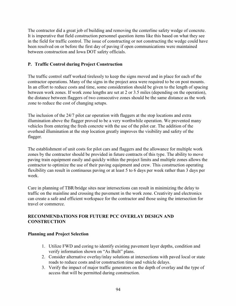
94
The contractor did a great job of building and removing the centerline safety wedge of concrete. It is imperative that field construction personnel question items like this based on what they see in the field for traffic control. The issue of constructing or not constructing the wedge could have been resolved on or before the first day of paving if open communications were maintained between construction and Iowa DOT safety officials.
P. Traffic Control during Project Construction
The traffic control staff worked tirelessly to keep the signs moved and in place for each of the contractor operations. Many of the signs in the project area were required to be on post mounts. In an effort to reduce costs and time, some consideration should be given to the length of spacing between work zones. If work zone lengths are set at 2 or 3.5 miles (depending on the operation), the distance between flaggers of two consecutive zones should be the same distance as the work zone to reduce the cost of changing setups.
The inclusion of the 24/7 pilot car operation with flaggers at the stop locations and extra illumination above the flagger proved to be a very worthwhile operation. We prevented many vehicles from entering the fresh concrete with the use of the pilot car. The addition of the overhead illumination at the stop location greatly improves the visibility and safety of the flagger.
The establishment of unit costs for pilot cars and flaggers and the allowance for multiple work zones by the contractor should be provided in future contracts of this type. The ability to move paving train equipment easily and quickly within the project limits and multiple zones allows the contractor to optimize the use of their paving equipment and crew. This construction operating flexibility can result in continuous paving or at least 5 to 6 days per week rather than 3 days per week.
Care in planning of TBR/bridge sites near intersections can result in minimizing the delay to traffic on the mainline and crossing the pavement in the work zone. Creativity and electronics can create a safe and efficient workspace for the contractor and those using the intersection for travel or commerce.
RECOMMENDATIONS FOR FUTURE PCC OVERLAY DESIGN AND CONSTRUCTION
Planning and Project Selection
1. Utilize FWD and coring to identify existing pavement layer depths, condition and verify information shown on “As Built” plans.
2. Consider alternative overlay/inlay solutions at intersections with paved local or state roads to reduce costs and/or construction time and vehicle delays.
3. Verify the impact of major traffic generators on the depth of overlay and the type of access that will be permitted during construction.

95
Overlay Depth Design
1. Review existing materials and “As Built” plans prior to making an overlay rehabilitation strategy proposal.
2. Core existing pavements to determine layer depth and condition. 3. FWD existing pavements to determine the best modulus values for each existing layer
in the spring of the year for lowest existing modulus values or weakest pavement condition.
4. Field review the project in the spring (poorest condition) and summer/fall (best condition) with regard to joint condition and widening movement and to determine the source of the distresses that the strategy is being designed to reduce or eliminate.
5. Communicate design limitations assumed in existing pavement structure with the goals of the owners before completing the depth design.
6. Examine the condition (distresses present, section depth, and modulus values) of bare pavements and consider options between bonded and unbonded overlay sections for the future pavement.
7. If bond breakers are applied to bare pavement sections, do not remove any of the bond breaker with milling, only scarify the surface to aid in bonding with the new PCC overlay.
Construction Communications
1. Add a public meeting after the preconstruction conference and before work begins in the field to allow the public to interact with the Iowa DOT and contractor staff. A short presentation by the contractor on the schedule of events will identify potential local conflicts and often allow time to avert them.
2. The meeting held on this project before paving began was helpful in alerting the public as to delays and times of entrance closures that might be expected.
Construction Staging
1. Provide the contractor with a staging plan that encourages the construction of erosion control measures, subdrain installation, patching, and shoulder/ditch work at the beginning of the contract, outside the working day charge period.
2. Reduce the working day time for overlay construction in reference to work done in recommendation 1 to 5 working days per mile.
3. Consider ways to design the transition and bridge approach section widths and depths of pavement that encourage the use of a slipform paving machine and minimize hand pours.
4. Make timely decisions on milling questions to allow the contractor to plan this activity to follow the bridge and other preliminary work in a timely manner.
5. Consider a contract period for overlays of 5 working days per mile.

96
Subdrain Installation
1. Provide a bid item note with the subdrain installation that alerts the contractor to potential subdrain repairs and pays for them by extra work order dependent of size of drain tile and extent of required work.
2. Consider allowing the subdrain operation to move forward immediately adjacent to the current work as soon as traffic control is moved forward and not jump two miles to the next site.
Concrete Full-Depth Patching
1. Allow for two consecutive work zones to be located 2 miles between flagger locations rather than 2 miles between the outermost warning signs. This approach would allow for more efficient use of time and materials by both the traffic control staff and the contractor by reducing the total number of work zones that may be required on a given project where multiple subcontractors are working at the same time.
2. Where PCC full-depth patches are selected for construction, the surface of the patch should be left clean (no surface application of bituminous materials) after construction to allow for proper bonding with the proposed concrete overlay.
3. Remove the sand seal from the top of PCC full-depth patches and bond the “thin” overlay (less than 6 inches in depth) to the full-depth patch.
4. Isolate full-depth patches from the surrounding pavement in “thin” overlays with transverse joints.
5. Develop full-depth patches across from each other in adjacent lanes to remove the chance for sympathy cracking across lanes.
6. Consider the use of two work zones (separated by 2 miles) for patching type work to allow the contractor to prepare patch areas by sawing in a second zone while removal and replacement is taking place in the first zone.
7. Consider omitting the calcium chloride from the patch mix for all patches in the spring and summer and encourage the use of maturity meters at the beginning, middle, and end of the day’s patches to estimate strength. Allow opening one hour before dark or when the strength of the patch reaches 350 psi flexural. Use the calcium chloride only when air and pavement temperatures do not support strength gain in the time between concrete placement and sunset.
Longitudinal Joint Patching
1. The researchers suggest that cores be taken in the areas of depressed longitudinal joints during the design phase to determine the cause of the depressions. These depressions may be such that longitudinal joint repairs will not change the situation and increasing PCC overlay depth over this area would be a greater benefit.
2. If the two-mile work zone is required with flaggers and pilot car, we suggest that the two miles be measured between the flaggers and not outermost warning signs for the reasons noted with full-depth patching.

97
3. Consider allowing the RCE to approve the use of a moving traffic control operation of a given distance for work such as this due to the methods the contractor suggests.
Miscellaneous Drainage and Grading Work
1. Allow the subcontractor to work within the same work zone as the other contractors (subdrain, patching, and bridge/transition paving) on either side of the roadway when work equipment does not encroach on the traveled way of either lane. This allowance aids in faster completion of short projects where the total length may be less than 5 miles and aids in the progression of critical path elements in longer projects.
2. Do a cost/benefit study of the proposed work during the design phase to determine whether it can be done best by local maintenance teams or by private contractor.
3. During the design phase, a review of existing cross road culvert condition, location and previous structure location and disposal could save the need for placing a new structure at these locations.
Bridge Approaches, Transitional Sections, and Shoulder Strengthening
1. Develop a transition section length at the end of the 70 foot bridge approach section with a 1 inch rise for every 25 feet from the low point at 60 foot from the bridge end to the elevation of the PCC overlay.
2. Construction bridge approach, transition and mainline overlays to the same width to allow slipform paving of all with one machine. Place the variable widths in the paved shoulder sections and shoulder-strengthening areas that most likely will be done by hand work.
3. If shoulder-strengthening units are planned, the units and TBR lengths should extend past the construction area for the combined bridge approach/transition sections. Where they extend past the transition areas, they should be jointed in the same spacing on each side of the road, as the overlay that will be placed in this area. In place of removal and replacement with the overlay widening unit they can be milled to depth of the overlay and replaced with the overlay concrete and tie bar configuration.
4. Where bridge approach slabs are to be replaced, the length of transition should include the bridge approach slab length where possible to reduce the overall length of the transition section. Two other considerations to apply in the development of the transition length include ability to drain water away from the bridge where possible along the roadway (minimum of the bridge approach distance) and assist in the development of a minimum length of vertical curve of 300 feet.
5. Layout of new bridge approach slabs and transitions should be accomplished in conjunction with the development of the roadway profile pavement grade line by the contractor. The layout can be accomplished with conventional string line or stringless surveying techniques.
6. Omit the construction of the shoulder strengthening on the side of the bridge or transition section that will be built in Stage 2 of the work.

98
Surface Surveys
1. In the design phase, consider two options for development of the PCC material quantities.
a. Add 20% to a theoretical quantity and do no preliminary survey work other that measuring wheel rut depths and cross slope at 500 foot intervals along the pavement length. Measurements should be taken in the summer months to eliminate the environment effect on widening units. This survey will prove an “estimate only” of existing conditions at the time of the survey to compare to a 20% addition in quantity. If this amount is added to the contract, utilize the Minnesota specifications and limit the contractor to staying within 2% of this estimated quantity. Do not allow for surface milling except to provide for scarification or specific identified locations by the RCE.
b. If the goal of the project is to minimize concrete yield, require the contract surveyor to survey at a minimum, the entire project at 50 foot intervals and 9 shot cross sections. The contractor should develop a centerline profile that limits removal based on the assumptions made by the pavement designer for remaining layer condition and depths. In this case, the target yield value for concrete quantity can be set at 6% plus or minus 2% for construction tolerances.
2. Investigate other ways of mapping the existing pavement surface prior to development of the finished grades for centerline and edges of pavement overlay that assure the nominal overlay depth will be maintained at centerline, and pavement quarter points and edges.
Surface Preparations for Overlays
1. Emphasize the need for communication within the highway agency design and construction staff during design and prior to construction to understand the overlay design assumptions and limitations in milling question considerations.
2. The contracting agency should consider coring HMA layers throughout the area under milling consideration to assure that an adequate depth of HMA will remain when the milling is complete to meet PCC overlay design assumptions.
3. Consider the following goals in determining the type and amount of existing surface preparation:
a. Need for removal of unstable surface layers b. Need to provide vertical clearance at key locations along the route c. Need to maintain a final centerline and shoulder elevation profile grade/cross
slopes to meet funding and safety requirements d. Need for an adequate existing surface to bond with the PCC overlay e. Need to minimize concrete overrun values f. Need to maximize surface ride values

99
Pavement Widening
1. Suggest in the contract plans that the widening trench be cut with equipment that can provide a vertical edge at the existing pavement that is equal to or better than that provided by a milling machine.
2. Identify in the plans how much trench depth, if any, will be required on the high side of super-elevated curve areas.
3. Clarify the width of the existing pavement lane that will be used as a reference for location of the widening unit to begin. The goal is to butt the new widening against the existing widening unit.
4. Operate the shoulder trench miller from the same model as the mainline pavement milling and paving to reduce the overrun in shoulder concrete and effectively build an 8 inch thick widening unit.
5. Mill the existing and proposed widening area to a depth of 8 inches below the proposed surface.
Pavement Overlay Paving Plan
1. Require the contractor to develop the paving plan that meets the project and contractor needs. The plan should consider efficiency in operations and use of people and equipment, the concrete delivery plan, material source locations and access to the plant, access from shoulder material sources to the completed work areas, public travel disruption, and local crossing access.
2. The contractor plan should be evaluated on its ability to deliver the completed pavement, shoulders and markings in the least amount of time and interference with the traveling and local public.
3. The application of the 3.5 mile work zone limit is adequate for this work. 4. Plans should allow for more than one paving work zone at a time to make efficient
use of contractor resources and time.
Construction
1. Require the contractor to have maturity recording devices that allow for a continuous set of values. This requirement can aid the contractor in bad weather conditions and provide a more accurate record in cases of dispute over joint development and opening times.
2. Consider maturity measurements as a trigger value for sawing in hot weather conditions where concrete placed in early morning, noon, and late evening cures at different rates.
3. Allow for additional haul road designations and local compensation to provide for raw material and concrete delivery throughout the project when the project is constructed by single lane under pilot car and flagger traffic control.

100
Traffic Control Solutions during Construction
1. Encourage the contractor to build bridge approaches and transition sections prior to or staged with the items such as subdrains, patching, and earthwork.
2. Delete the construction of the centerline safety fillet in pilot car operation areas where traffic is limited to following the pilot car and only one lane is open to traffic in the work area.
3. Provide plan notes that allow the contractor to use multiple work zone setups simultaneously as allowed by plan and project limits. This allowance will assist the traffic control contractor planning.
4. Allow work by equipment on the shoulders across the road from a lane closure to proceed at the same time as the lane closure operation.
5. Reduce the distance required between work zones to 2 miles between flagger stations versus the current 2 miles between outermost warning signs.
6. Keep the 3.5 mile length for paving work zones. Allow the contractor to close local road crossings in a work zone only when those in the adjacent one are open to traffic.
7. Allow and encourage the use of three leg signal operations and extended TBR lengths in locations where bridges and intersection reconstruction are adjacent to reduce overall construction time and traffic disruption.
8. Encourage the use of the lane paving, shoulder construction, and pavement marking process used on this project before allowing paving of the adjacent lane or moving traffic control forward.
9. Continue the use of the HMA runout shown on plate 7308 for all situations that will result in its use for more than one month in duration.
10. Allow the contractor to suggest alternative materials that provide a 6 feet per1 inch of overlay depth, slope in runout for locations that will be temporary in nature (less than one month). Materials may include PCC over a geotextile bond breaker, compacted millings, recycled plastic materials, or other materials approved by the engineer. Payment shall be lump sum for each installation. Maintenance of the materials shall be incidental and include the installation and removal of the material.
11. Employ split barricades one mile each way from the project to alert heavy equipment of road closures. The post-mounted signs on this project did not communicate the closure.
12. Add an advisory sign at each end of the project to warn drivers of traffic delays such as Road Construction Next ____ Miles, Expect Traffic Delays.
13. Consider the use of portable signs versus post-mounted for traffic work zones to aid in flexibility of work sites.
14. Consider a clearance behind the TBR at bridge repair and transition construction sites of the width of pavement plus 4 feet on each side to allow for slipform paver operation.
15. Consider the application of three approach traffic signal systems where bridge work and intersection reconstruction involve one common work site and paved local roads.
16. Omit the construction of the centerline safety wedge where traffic is maintained in only one lane with the use of the pilot car on a 24/7 hour basis.

101
APPENDIX A. CONTRACTOR PAVING PLAN AND CPM CHART

102

103
APPENDIX B. HAUL ROAD MAP

104
APPENDIX C. CONCRETE MIX DESIGN AND PROPERTIES
800240 c
om
pu
ter
VE
R 1
-06
PC
C P
lan
t R
ep
ort
E -
Un
its
Ch
ec
k M
ix(
x )
Ch
ec
k O
ne
( x
)S
EN
D
Da
te o
f P
lac
em
en
tF
rom
To
Pro
jec
t N
o.:
N
HS
X-0
18
-7(5
8)-
-3H
-19
Co
ntr
ac
t ID
: 1
9-0
18
7-0
58
-AR
ep
ort
No
.:
5C
en
tra
lX
Pa
vin
gX
(D
aily
)
Mix
19
/14
/11
70
1+
87
.3P
lan
t N
am
e:
AL
PH
A S
an
d P
itC
ou
nty
: C
hic
ka
sa
w-
Fa
ye
tte
Da
te T
his
Re
po
rt:
09
/14
/11
Re
ad
y
Str
uc
ture
(
We
ek
ly)
Mix
29
/14
/11
63
9+
75
Co
ntr
ac
tor:
M
AN
AT
TS
Te
mp
. M
in:
49
ºFD
ate
Of
La
st
Re
po
rt:
08
/30
/11
No
nc
riti
ca
l
(W
ee
kly
)
Mix
3S
ub
Co
ntr
ac
tor:
T
em
p. M
ax
: 5
9ºF
Str
uc
ture
s D
es
. N
o:
Pa
tch
ing
(
We
ek
ly)
Mix
4W
ea
the
r:
Clo
ud
y
Mix
5
Fin
e A
gg
reg
ate
Inte
rme
dia
te A
gg
reg
ate
Co
ars
e A
gg
reg
ate
A
ctu
al Q
ua
nti
tie
s U
se
d -
lbs
/yd
3A
vg
Ma
x
Mix
Ba
tch
ed
% O
f E
st.
Mo
ist.
T-2
03
Wt.
SS
DM
ois
t.T
-20
3W
t. S
SD
Mo
ist.
T-2
03
Wt.
SS
DW
ate
rw
/cw
/c
yd
3U
se
d(%
)S
p. G
.lb
s(%
)S
p. G
.lb
s(%
)S
p. G
.lb
sC
em
en
tF
ly A
sh
GG
BF
SF
ine
Inte
r.C
oa
rse
In A
gg
.P
lan
tG
rad
eR
ati
o R
ati
o
QM
C7
52
.00
10
3.8
1.2
2.6
41
,32
10
.52
.69
48
00
.12
.69
1,3
32
44
81
12
1,3
37
48
21
,33
32
01
99
.00
.39
10
.45
0
QM
C9
84
.00
10
3.8
2.5
2.6
41
,32
10
.52
.69
48
00
.22
.69
1,3
32
44
81
12
1,3
55
48
21
,33
53
91
98
.10
.42
30
.45
0
Co
ars
e1
1
/2"
1"
3/4
"1
/2"
3/8
"#
4#
8#
20
0C
om
ply
(X)
lbs
/yd
3B
atc
he
d
42
.21
00
95
-10
02
5-6
00
-10
0-5
0-1
.5Y
/N Ic
e
To
da
yW
ee
kT
ota
l
9/1
4/1
1 C
A-1
10
09
76
32
69
.21
.30
.90
.6Y
He
ate
d W
ate
r C
he
ck
On
e (
X)
X
To
Da
te
9-1
4-C
A-2
10
09
78
14
52
65
.90
.90
.5Y
He
ate
d M
ate
ria
ls
Co
nc
rete
:
yd
31
,73
6.0
02
,41
5.0
0
Ce
me
nt:
to
ns
38
8.8
6
54
0.9
6
Inte
rme
dia
te1
1
/2"
1"
3/4
"1
/2"
3/8
"#
4#
8#
20
0C
om
ply
Bra
nd
/ S
ou
rce
Ra
te L
ot
Nu
mb
er
15
.29
/14
/11
IA
-11
00
10
01
00
10
01
00
46
2.9
0.6
NA
Air
En
tra
inin
g:
B
rett
(E
uc
lid
) A
EA
-92
6.8
oz p
er
ya
rd
9-1
4-I
A-2
10
01
00
10
01
00
10
02
91
.40
.5N
AW
ate
r R
ed
uc
er:
B
rett
(Eu
clid
)WR
-91
5 o
z. p
er
c.w
.t.
N
A R
eta
rde
r:
Ca
lciu
m C
hlo
rid
e:
Fin
e1
/2"
3/8
"#
4#
8#
16
#3
0#
50
#1
00
#2
00
Co
mp
ly S
up
erp
las
tic
ize
r:
42
.61
00
90
-10
07
0-1
00
10
-60
0-1
.5Y
/N
9/1
4/1
1 F
A-1
10
09
68
77
24
81
21
0.5
Y
9-1
4-1
1F
A-2
10
09
38
26
63
99
.61
.10
.8Y
Ty
pe
Sp
. G
r.S
ou
rce
Ce
me
nt:
1
3.1
4 P
C0
40
1 L
eh
igh
Fly
As
h:
C
2
.69
FA
00
8C
La
ns
ing
H
ea
dw
ate
rs
GG
BF
S:
1 1
/2"
1"
3/4
"1
/2"
3/8
"#
4#
8#
16
#3
0#
50
#1
00
#2
00
Wit
hin
CW
Ta
rge
t9
5-1
00
94
-10
08
4-9
46
8-7
86
0-7
04
2-5
23
3-4
12
7-3
51
7-2
54
.1-1
00
-3.1
0-1
.5T
arg
et
Zo
ne
T-2
03
A
#G
rad
. N
o.
10
09
98
46
96
24
83
7.9
31
.42
1.1
5.6
0.9
0.6
YII-A
Co
ars
e:
A
33
02
43
10
09
99
27
76
94
73
5.5
28
.61
7.1
4.5
0.8
0.6
YII-A
Inte
rme
dia
te:
A3
30
24
Fin
e:
A
33
50
61
Re
ma
rks
1 S
T d
ay
of
ma
inlin
e w
es
tbo
un
d o
ut
of
We
st
Un
ion
C.P
.I.:
G
reg
Ha
ns
en
CI 8
09
Dis
trib
uti
on
: _
__
__
D
ME
_
__
__
P
roj. E
ng
. _
__
__
P
lan
tM
on
ito
r:
Ja
so
n M
oh
orn
eN
E2
11
Lo
ca
tio
n
Alp
ha
Nie
ma
nn
"s
Wa
uc
om
a N
iem
an
n's
24
06
yd
s Q
MC
pla
ce
d t
o d
ate
9
C.Y
. T
OT
AL
W
AS
TE
TO
DA
TE
0 Y
ard
wa
ste
to
da
y o
n g
rad
e 9
/14
/11
Ad
jus
ted
% P
as
sin
g C
alc
ula
ted
Co
mb
ine
d G
rad
ati
on
Co
nc
. T
rea
tme
nt
Wa
uc
om
a N
iem
an
n's
So
urc
e
B0
62
91
1
B0
52
41
1